Johnny Square - Johnson Level · Johnny Square ® INSIDE BACK COVER IS BLANK The versatility and...
67
NEW Continuous Scribing Notches–Ideal for Ripping at 3-1/2" and 5-1/2". ¡Nuevo! Bordes continuos con muescas para marcaciones ideales para efectuar cortes a 3-1/2" y 5-1/2". RAS-1 7" 18cm 7" Professional Aluminum Rafter Angle Square with Rafter Square Instruction Book and Tables Escuadra Profesional de 7" para Ángulos de Vigas con manual de instrucciones y tablas para envigado incluidos Johnny Square ®
Transcript of Johnny Square - Johnson Level · Johnny Square ® INSIDE BACK COVER IS BLANK The versatility and...

NEW Continuous Scribing Notches–Ideal for Ripping at 3-1/2" and 5-1/2".
¡Nuevo!Bordes continuos con muescaspara marcaciones idealespara efectuar cortesa 3-1/2" y 5-1/2".
RAS-17"18cm
Made in USA Hecho en EE.UU.Patents Pending Patentes Pendientes
©2012 Johnson Level & Tool Mfg. Co., Inc.Mequon, WI 53092
Montréal, Québec, Canadawww.johnsonlevel.com
7" Professional Aluminum Rafter Angle Squarewith Rafter Square Instruction Book and Tables
Escuadra Profesional de 7"para Ángulos de Vigascon manual de instrucciones y tablas paraenvigado incluidos
MARKING EDGEBorde para marcado
TOP CUTS/HIP & VALLEY
RAFTER SCALEEscala para cortes
superiores y cortes enángulo estilos Hip y Valley
COMMON RAFTER SCALEEscala común para ángulos de vigas
DEGREE SCALE/PROTRACTOREscala degrados/transportador
“T”-BAR(FOOT)Base paraángulorecto
1/4" SCALE(1" TO 3-1/2")Escala de 1/4"(entre 1" y3-1/2")
PIVOTPivote
SCRIBING NOTCHES (1" TO 5-1/2")Muescas para marcaciones (entre 1" y 5-1/2")
RAFTER SEAT CUTIndicación para corte de asiento
Johnny Square®

INSIDE BACK COVER IS BLANK
The versatility and durability of Johnson’s“Johnny Square®” came to us fromprofessional master carpenter Johnny Wong,an accomplished homebuilder with morethan twenty-five years experiencein the trades.
Johnny’s crews were never satisfiedwith their rafter squares’ inability to allowfor fast and accurate measurementsfor rip cuts. With more than three years offield testing, the “Johnny Square®” helpsprofessionals like Johnny do more workin less time.
Johnson®—TOUGH, RELIABLE, ACCURATE

1
The Johnson® Rafter Angle SquareThank you for purchasing the Johnson® Rafter Angle Square. Since 1947 Johnson Level & Tool has been developing solutions to help professional tradesmen improve their work. Our products are trusted by professionals worldwide to work more accurately, more quickly and more reliably.
This reference book will serve as a guide for providing basic rafter and angle layout information through various illustrations and tables. Johnson Level & Tool is not responsible for any errors or omission with the content of this book. The information outlined is to be used as a recommendation however other methods not listed may be acceptable practice.
The Johnson® Rafter Angle Square is available in 7 inch and 12 inch sizes to accommodate various material dimensions.
Here’s what makes Johnson® Rafter Angle Squares fast and efficient:
•Thenewandimproved7inchhascontinuousscribinggrooves from 1 inch through 5-1/2 inches. (Please see illustration 1 on page 2)
•Easytoreadanglescalefrom0°to180°.
•Onenumberlayoutfor:Roofs, solar panel supports, stairs, cabinets, trim work and many other layout projects.
•Therafterscalesarelaidoutmathematicallytoavoidtime consuming calculations.
•The12inchhascontinuous1/4inchscribinggroovesfrom 1-3/4 inches through 9 inches.
•Bothrafteranglesquaremodelsserveasasawguidefor fast cuts.
For additional information on the Johnson® Rafter Angle Square family of products please visit www.johnsonlevel.com

2
MARKINGEDGE
TOP CUTS/HIP & VALLEY
RAFTER SCALE
COMMON RAFTER SCALE
DEGREE SCALE/PROTRACTOR
“T”-BAR(FOOT)
1/4" SCALE(1" TO 3-1/2")
PIVOT
SCRIBING NOTCHES(1" TO 5-1/2")
RAFTER SEAT CUT

3
TABLE OF CONTENTS
Types of Rafters . . . . . . . . . . . . . . . . . . . . . . . . 4
Rafter Measurements . . . . . . . . . . . . . . . . . . . . . 6
InchestoFeetConversion(TableA) . . . . . . . . . . . . . 9
Common Rafters . . . . . . . . . . . . . . . . . . . . . . . . 9
Common Rafter Layout . . . . . . . . . . . . . . . . . . . . 12
Hip and Valley Rafters . . . . . . . . . . . . . . . . . . . . . 15
Hip Rafter Layout. . . . . . . . . . . . . . . . . . . . . . . .18
Intersection of Hips on Ridge . . . . . . . . . . . . . . . . . 19
Valley Rafter Layout . . . . . . . . . . . . . . . . . . . . . .20
Jack Rafters. . . . . . . . . . . . . . . . . . . . . . . . . . . 22
Jack Rafter Layout . . . . . . . . . . . . . . . . . . . . . . . 25
Dormer Rafters . . . . . . . . . . . . . . . . . . . . . . . . . 26
Door Overhang . . . . . . . . . . . . . . . . . . . . . . . . . 26
Degree Scale . . . . . . . . . . . . . . . . . . . . . . . . . . 27
StairLayoutExample . . . . . . . . . . . . . . . . . . . . .28
SolarPanelLayoutExample. . . . . . . . . . . . . . . . . . 34
Rafter Length Tables . . . . . . . . . . . . . . . . . . . . . .40

4
TYPES OF RAFTERS
COMMON RAFTER:Arafterthatrunsperpendicular(90°)from the wall plate to the roof ridge when looking straight down at the roof. When looking from the side, its length formsthediagonalleg(orhypotenuse)ofarighttrianglethat has its vertical leg equal to the rise and its horizontal leg equaltotherun(seeFigures1,3and8).
VALLEY RAFTER: A rafter that runs from the wall plate to theroofridgeattheintersectionofthegableextensionwiththemainroof(seeFigures1,8,12and13).
VALLEY JACK RAFTER: A rafter that runs from a valley rafter totheroofridge,90°fromtheroofridge(seeFigures1,8and 15).
HIP RAFTER: A rafter that runs diagonally from the top of the wall plate to the roof ridge, so as to form an outside corneroftheroof(seeFigures1,8,9and10).
HIP JACK RAFTER: A rafter that runs from the top of the wallplatetoahiprafterat90°tothewallplate(seeFigures1,8and14).
CRIPPLE JACK RAFTER: A rafter that runs from a hip rafter toavalleyrafter,perpendiculartotheroofridge(seeFigures1and8).
DORMER RAFTER: A rafter which sets on top of the main roof without cutting into it, thus causing the main roof not to weaken.Forexample,whenremodelingorwhensolarpanelsareadded(seeFigure1).

5
FIG
. 1 T
ypes
of
Raf
ters
. All
cuts
on
this
roo
f ca
n b
e m
ade
by u
sing
the
nu
mb
er 8
(i.e
. an
8 in
ch r
ise)
.

6
RAFTER MEASUREMENTSThe use of our square for rafter layout is based on two simple and commonbuildingmeasurements:(1)therafterrun,and(2)therafter rise. These are available from either the building blueprints, drawings, or actual measurements. The tables included in the back of this book are also based on these two simple measurements (seeFigures2and3,andalsothetablesstartingonpage40).RAFTER RUN: Run is the horizontal or level distance the rafter will span. It is measured in feet.RAFTER RISE: Rise is the vertical distance of a rafter between its highest and lowest points. It is measured in feet.INCH RISE: The rise measured in inches per foot run. It is also called“InchRisePerFootRun.”Itcanbecalculatedwiththefollowing formula: INCH RISE RAFTER RISE (ft) x 12 OR = (SCALE NUMBER) RAFTER RUN (ft)The Inch Rise gives you the corresponding scale number to use onthesquare(forthecommon&hip-valscales).Itisalsothe“onenumberbywhichyoucanframetheroof.”The inch rise, the rafter run and the tables in the back of the book are all that are needed to lay out rafter lengths and the cuts for common, hip, valley and jack rafters. The instructions outlined below show the step-by-step procedure to follow for basic roof construction.STEP 1. OBTAIN RAFTER RUN: Measure or calculate the horizontal distance the rafter will span, starting at the outside of the wall on which it will rest. Include any boarding on the wall if it extendstothewalltopplate(seeFigure3).When measuring building width to obtain rafter run, use a steel tape if possible so that you can measure the full width of the building. Measure from outside to outside of the wall or the top plate on whichtherafterwillrest.Ifboardingextendsuptothetopplate,measurement is to be taken from outside of the boarding.

7
FIG. 2 Rafter Runs and Rises for Different Style Roofs.

8
FIG. 3 The Common Rafter.
Then the run is found by dividing in half the building width. Whenaridgeboardisbeingused,deduct1/2itsthicknessfrom the run.
STEP 2. OBTAIN ROOF RISE: Find the distance you wish the roofridgetobeabovethewall(infeet)bymeasuring,calcu-latingorobtainingitfromtheblueprints(seeFigure2).
INCHRISEPERFOOT RUN
RISEX12
RUNRAFTERLENGTH
RUN2+RISE2 OR
USETABLES
= =
9
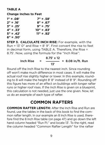
TABLE AChange Inches to Feet1" = .08' 7" = .58' 2" = .16' 8" = .67' 3" = .25' 9" = .75' 4" = .33' 10" = .83' 5" = .42' 11" = .92' 6" = .50'STEP 3. CALCULATE INCH RISE:Forexample,withtheRun=13'0"andRise=8'9".Firstconverttherisetofeetindecimalform,usingTABLEA.Therefore,theRise=8.75'.Now,usingtheformulaforthe“InchRise”:
8.75' x 12 Inch Rise = = 8.08 in/ft. Run 13'Round off the Inch Rise to the nearest inch. Since rounding off won’t make much difference in most cases. It will make the actualroofriseslightlyhigherorlower.Inthisexample,round-ingto8willmaketheheight8'8"insteadof8'9".Roundingoffthis figure has more of an effect on buildings with longer rafter runs or higher roof rises. If the Inch Rise is given on a blueprint, this calculation is not needed, just use the one given. Now, let usdoanexampleofeachtypeofrafter.
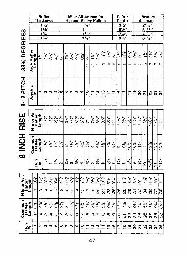
COMMON RAFTERSCOMMON RAFTER LENGTH: After the Inch Rise and Run are found, use the tables in the back of this book to find the com-monrafterlength.Inourexamplean8InchRiseisused,there-forefindthe8InchRisetable(onpage47)andgodownthelefthandcolumnheaded“RunFt.”andlocate13'.Totheright,readthecolumnheaded“CommonRafterLength”fortherafter

10
FIG. 4 Common Rafter Layout.
length.Forourrafterweget15'7-1/2".Thisistherafterlengthfromthetopcuttotheseatplumbmark(seeFigure4).
NOTE:Forarungreaterthanthatgiveninthetables,simply add any two runs that will equal the run desired. Then find the lengths for those two rafters and add them together.Forexample,saythatyourrunis38',addthelengthfora18'runandthelengthfora20'runtogether.Or add a 15' run’s length and a 23' run’s length together.
TAIL OR EAVE LENGTH: The tail or eave overhang now mustbeaddedtotherafterlength(seeFigure5forsug-gestedeaveconstruction).Withourexample,letususe

11
FIG. 5 Suggested Eave Construction.

12
atailrunof1'9".Inthesame“Common”tableasusedabove,foran8”rise,wefind: 1' Run = 1' 2-1/2" 9" Run = 10-7/8" 1' 9" Tail = 2' 1-3/8"COMMON RAFTER LUMBER LENGTH: To obtain the total length of the rafter, an allowance for the bottom plumb cut mustnowbemade(seeFigure4).Thisallowancecanbeobtainedbyusingthetables.Inourexample,letususea2x6pieceoflumberwhichwillgiveusadepthof51/2inches.Fromthebottomallowancetable(using8"riseagain),thecommonandjackallowanceequals3-11/16inches.Thetotalcommon rafter lumber length then becomes: RAFTER LENGTH = 15' 7-1/2" TAIL = 2' 1-3/8" BOTTOM ALLOWANCE = 3-11/16" TOTAL LUMBER LENGTH = 18' 0 9/16"
COMMON RAFTER LAYOUTSTEP 1. TOP PLUMB CUT: In choosing the side of your raftertouse,putthecrown(highside)upiftherafteris not straight. Now starting at the top of the rafter, lay oursquareonthefaceoftheraftersothatthe“T”barisdrapedoverthetopedgeoftherafter(seeFigure6).While holding the pivot point firmly against the edge of therafter,pivotthesquaresothatthenumber8onthecommon scale lines up with the edge of the rafter. Starting from the pivot point, mark the top plumb cut line along the top edge of the square.STEP 2. SEAT NOTCH OR BIRD’S MOUTH: With your rafter length(inourexample15'7-1/2"),measuredownalongthetop edge of the rafter and mark another plumb line as you did in Step 1. This line represents the outside wall of your

13
FIG. 6 Top Plumb Cut of a Common Rafter.

14
building.Nowlineupthedashedline(abovethe80°incre- mentonthesquare)withtheplumbmark(seeFigure7A&7B). Draw the horizontal seat mark, a perpendicular line, along the bottom of square. Never notch more than halfway through the rafter and make all seat notches the same depth.STEP 3. TAIL OR BOTTOM PLUMB CUT: Using your tail length(2'1-3/8"inourexample),measuredowntherafterfrom the seat plumb line and mark the bottom plumb line
FIG. 7ASeat Notch orBird’s Mouth Layout.
FIG. 7BSeat Notch or
Bird’s Mouth Layout.

15
as you did in Step 1. You may wish to leave the tails long un-til all the rafters are in place, so that you can mark the ends to a line and then cut.
NOTE:Thetopandbottomcutsontherakeboardarealsodone in the same way as a common rafter but the distance from the top cut to the bottom cut is the rake board length.
HIP AND VALLEY RAFTERSThe hip and valley rafters are treated very similarly because bothrunata45°angletothecommonrafter,andtheyboth form the diagonal or hypotenuse of a right triangle (seeFigure8).Thethreesidesbeingthehip,plateandcommon rafter, or the valley, ridge and common rafter. Therefore, the cuts and lengths apply equally to hip and valley rafters.
FIG. 8 Top View Rafter Definition.
FIG. 7ASeat Notch orBird’s Mouth Layout.

16
FIG. 9 View of Hip Rafter Layout.
HIP-VAL LENGTH: Use the table on page 47 to obtain the hiporvalleyrafterlength(continuingthe8InchRiseex-amplefrompage9,Step3).Inourexamplean8InchRiseisused,thereforefindthecolumnheaded“RunFt.”andlocate 13'. To the right read the column headed “Hip or Val. RafterLength”andfindalengthof20'3-7/8"(seeFigures8,9,10,12and13).

17
TAIL OR EAVE LENGTH: Use the same procedure as you did for the common rafter but remember to use the Hip-Valcolumn.Againwehaveinourexampleatail1’9”long,thus giving us:
1' Run = 1' 6-3/4" 9" Run = 14-1/8" 1' 9" Tail = 2' 8-7/8"
NOTE:Ifamiterisdesired,addforhiporvalmiterallow-ancefromthetables(seeFigures10and13).
HIP-VAL LUMBER LENGTH: Add an allowance for a bottom plumb cut and, if used, a miter. Obtaining from the table theallowanceforthebottomplumbcut(usinga2x6)
FIG. 10 Hip Rafter Layout.

18
andamiterallowance(usinga11/2"actualrafterthick-ness) we get: RAFTER LENGTH = 20' 3-7/8" TAIL LENGTH = 2' 8-7/8" BOTTOM PLUMB ALLOW. = 3-11/16" MITER ALLOWANCE = 7/8" LUMBER LENGTH = 23' 5-5/16" NOTE:Onlyaddmiterallowancesiftheyareused.
HIP RAFTER LAYOUTSTEP 1. TOP PLUMB CUT: The square is used in the same manner as in Step 1 of the common rafter top plumb cut. Butnow,readtheInch-RiseontheHip-Valscaleinstead.Remember that the top plumb cut is a bevel cut and that oppositerafterswillhaveoppositebevelcuts(seeFigures9and10).Thereforewhenplacingthesquareontherafter,placeitonthelongsideofthebevel(thebevelcutwillbeexplainedinStep4).STEP 2. SEAT NOTCH: Measure the rafter length down along the top of the rafter and make the seat plumb mark inthesamemannerasyoudidforthecommonrafter(inourexampleitis20'3-7/8").Next,measurealongtheseatplumb mark the seat depth and using the dashed line on the square, draw a perpendicular line for the horizontal seatmark(seeFigure10).Besureallhorizontalcutsforallrafters are the same distance from the top edge of the raf-ter at the wall line. For the proper fit of the hip rafter, cut thetopwallplatecorneroff(asshowninFigure9).Thisallows Hip seat notch to set in against a full flat corner, rather than against an outside point. STEP 3. TAIL OR BOTTOM PLUMB CUT: Measure down the top of the hip rafter from the seat plumb mark and mark thedistanceforthetail(inourexample2'8-7/8").Usingour square, make the bottom plumb mark. If a tail miter is

19
used, make another plumb mark on the other side of the raf-terjustoppositeofthebottomplumbmark(seeFigure10).STEP 4. CUTTING HIP RAFTER PATTERN: With your saw setat45°,cutthetopplumbcut,makingsurethetopbevels are opposite for opposite rafters. Setting the saw at45°automaticallygivestheplumbcutandthesidecutbevel.Makebottomplumbcutona45°angleifmiterisused.Ifabevelisnotneeded,setsawat90°.Theseatnotchismadewiththesawat90°(seeFigures9and10).
INTERSECTION OF HIPS ON RIDGETo find the intersection points of the hip on the ridge rafter, cut ridge one foot longer at the point where hips intersect the ridge. With a regular length common rafter, set the seat notch cut over the edge of the top plate, in line with the ridge(seeFigure11).Makingsureyourwallsarestraight,place top end of common rafter even with top of ridge.
FIG. 11 Intersection of Hips on Ridge.

20
Nowmarkacrosstopofridge(asshown).Thismarkwillbethe center of the two intersecting hips. If a common rafter is to be used, the ridge will be cut off at this mark and the commonrafterbuttedupagainstit(seeFigure9).Ifnocommonrafterwillbeused,cuttheridgeabout2"longer.This will allow you to nail through the ridge into the hip.
VALLEY RAFTER LAYOUTSTEP 1. TOP PLUMB CUT: Using the Hip-Val scale again, make the top plumb mark in the usual way. Now measure down the top of the rafter from this mark for a miter allow-ance,ifused(seeFigures12and13).Lookuptheallowanceinthe Tables under the rise and the rafter thickness that you are using(inourexample:8"riseand1-1/2"actualrafterthickness,resultingina7/8"allowance).Thenmaketwoplumbmarksonboth sides of the rafter for the top plumb bevel cuts.
STEP 2. SEAT NOTCH: From the first top plumb mark, measuredowntherafterlength(inourexample:20'3-7/8")andmaketheseatplumbmark(seeFigure13).Now,godown the rafter from the seat plumb mark the miter al-lowancedistance(foundinthetableforyourinchriseandactual rafter thickness) and make a plumb line for the miter allowance. Draw the same miter plumb line on the other side of the rafter for making the bevel cut. This mitered seat cut will allow the valley rafter to fit down over the crotch formedbythejoiningwallplates(seeFigure12).Next,tomake the horizontal seat mark, measure down to the seat depthontheseatplumbmark(notthemiterplumbline).Aligning the dashed line on our square with the seat plumb mark, draw a perpendicular line using the bottom edge ofourSquaretotheedgeoftherafter.Alsoextendthehorizontal seat mark to the added miter allowance plumb line(seeFigures7and13).Doublechecktoseethatallseatnotches are the same depth.

21
STEP 3. BOTTOM OR TAIL PLUMB CUT: Measure down the topofthevalleyrafterfromtheSEATPLUMBMARKandmarkthetaillength(inourexample:2'8-7/8").Besuretoadd the miter allowanceinthemeasurement,ifused(seeFigure 13). Make the bottom plumb mark with the square in the normal manner.
STEP 4. RAFTER PATTERN CUTS: To make the top and bottomcuts,tiltthesawat45°(seeFigure13).Alsomaketheseatmitercuts.Nowchangethesawtiltto90°forthehorizontal seat cut. You may want to check for proper fit and use this rafter as a pattern for the other valley rafters.
FIG. 12 View of Valley Rafter Layout.

22
JACK RAFTERSJACK RAFTER LENGTH: The Jack Rafter Tables are differ-ent than those for the other rafters. The table lists, in the first column, the varying center-to-center spacing of the jack rafters. Then in the second column is the difference in lengthfromonejacktothenext(seeFigures14and15).This difference in length is to be added to or subtracted from the rafter length as you progress from jack to jack (usingthespacingselected).Inourexampleofa8"rise,andletsassumea24"spacing;wehavea2'4-7/8"differ-ence in length. Therefore, to obtain the length of the first or longest jack rafter, measure the distance from the edge
FIG. 13 Valley RafterLayout.

23
FIG. 14 Top View of Hip Jack Rafter Spacing.

24
distance from the edge of the last common rafter to the intersection of the hip and ridge, or the valley and top plate(foravalleyjack).Thismeasurementiscalled(P)inFigures14and15.Nowsubtractthemeasurement(P)fromthespacingyouareusing(W).Theresult(W–P)isthe distance from the intersection of the hip and ridge to the first hip jack or the plate corner to the first valley jack. Look in the table for this distance and find the length to deductfromthecommonrafterlength.Inourexampleagain,letustakeameasurmentof12"fromthecommonrafter far side edge to where the hip intersects the ridge (W–P=24–12=12).Therefore:
FIG. 15 Top View of Valley Jack Rafter Spacing.

25
COMMON RAFTER LENGTH = 15' 7-1/2" SUBTRACT (W – P) FROM TABLE = 1' 2-3/8" FIRST HIP JACK RAFTER LENGTH = 14' 5-1/8"The tail length must now be added to this length. For all remainingjacks,subtractthefullspacing(W).Example:finding in the tables the amount to subtract for a spacing of24",weget: FIRST HIP JACK RAFTER LENGTH = 14' 5-1/8" SUBTRACT (W) FROM TABLE = 2' 4-7/8" SECOND HIP JACK RAFTER LENGTH = 12' 0 1/4"Continue with this process until you get to the last jack rafter(theprocessisidenticalforvalleyrafters).Alwaysremember to measure the jack rafter length on the long side of the rafter because of the bevel.Cripplejacks(seeFigure8)usethesamemethodasabove, but must be beveled at both ends. Therefore, the subtraction for both ends must be made from a common rafter length as if it went from the plate to the ridge. The cripple jack rafters are actually being measured from long pointtolongpointdiagonallyalongthetopedge.Bymea-suringdiagonally,youwillcompensatefor1/2ofthehipthicknessand1/2ofthevalleythickness.TAIL OR EAVE LENGTH: The tail or eave length for all hip jack rafters is the same as for common rafters. If desired, use a common rafter for a pattern. Cripple and valley jacks havenotail(SeeFigures14and15).LUMBER LENGTH: The lumber length is found by using the same procedure outlined for common rafters, but sub-tractingfortherafters’position(seeabove).
JACK RAFTER LAYOUTJACK RAFTER LAYOUT CUTS: Seat notches and bottom plumb cuts for hip jack rafters are the same as for com-mon rafters.

26
The common scale on the square is used for all jack rafters. Whenever a jack rafter rests against a hip or valley rafter, mark aplumbcut,andthencutata45°alongthemark.Thiswillgive both the side cut and the plumb cut. Angles should be checked for direction before cuts are made. See Figures 11 and 14 for the center common rafter at the end of the ridge.
DORMER RAFTERSSometimes when adding a room or remodeling, it is easier to build a valley on top of the main roof. This saves cutting into the main roof that could cause weakening. STEP 1. Referring to Figure 1, mark location of valley on roof at 45°tocommonrafters.Thensetlongpointofbottomendofrafterevenwiththemarkjustmadeatline“A”.STEP 2. PLUMB CUTS ON THE DORMER RAFTER: Using what-ever inch rise has been determined, make them the same as the common rafter.STEP 3. RAFTER LENGTH: Once the shortest rafter is mea-sured, the rafter length may be determined using the same method as with jack rafters.STEP 4. BOTTOM CUT: The heel or bottom cut is the same as thehorizontalcutoftheseatnotch(seeFigure7).Butcutallthewayacrosstherafter(andwithoutmakingaseatplumbcut). The saw should be tilted at the same angle as the rise of the roof. Thus allowing your horizontal cut to lay flat against the roof.Forexample,usingthecommonscalewithan8"rise,youwillnoticethatthenumber8linesupat331/2°onthedegreescale.Sotiltyoursawat331/2°beforemakingthebottomcut.
DOOR OVERHANGInFigure1ispicturedaroofextensionthatmaybefoundoveradoorway.Tofindtheendcutatpoint“B,”holdthesquaresothatthe“T”barisflatagainsttherafter.Thenusingthecom-monrafterscale,makeamarknexttotheinchrisethatwasused for the main roof. Now draw a line from the mark just made to the pivot point. This is then the cut required for a flat

27
roof. For a pitched roof, use the angle scale and make your marknexttotheanglethatistheresultoftheroofinchriseangle minus the overhang inch rise angle.
DEGREE SCALEWith the degree scale on our square, any angle can be found onaboard.Figure16showsacoupleofexamples.Tofindanobtuseangle,forexample105°,putthepivotpointonthemark where the cut is to be made. Lay the square so that the “T”barisheldtightagainsttheboardanddrawaperpendicu-lar line across the board. Now flop the square on its opposite side(makingsureyou’reusingthesamepivotpoint)andpivotthesquaresothedegreescalereads15°(105°-90°).Scribinga line along the bottom edge of the square now gives you a 105°angle(andalsoa75°angleanda15°angle).
FIG. 16 Resulting Angles Using the Degree Scale on a Board.

28
STAIR LAYOUT EXAMPLEWith our square, stair layout can be done simply and efficiently. The layout can be done without hours of calcula-tions.Basicmathandtheuseofacalculatorwithasquareroot function are all that are needed.
STEP 1. FIND STEP MEASUREMENTS: We start with the to-talrise(seeFigure17)tofindthenumberofstepsrequired.If the rise is not known, measure the vertical distance between the lower finished floor and the upper one. When-ever a quantity is known, use it instead of calculating it.
NOTE 1Beforestartingyourlayout,checklocalandstatecodes for tread width, length and step rise requirements. Many states have stairway construction regulations.
NOTE 2 It’s a good idea to check your layout on paper or cardboard before cutting out the wood steps.
FIG. 17 Stair Layout.

29
1.Findtheapproximatenumberofstepswiththefollowing formula: TOTAL RISE (inches) APPROXIMATE NO. OF STEPS = 7" Forexample,let’sassumea8'6"rise=102” 102" APPROXIMATE NO. OF STEPS = 7" = 14.57"NOWTHEACTUALNUMBEROFSTEPSWOULDBETHEWHOLENUMBER,IGNORINGANYFRACTION,i.e.,14STEPS.Next,findtheactualsteprisebyusingthefollowingcomputation. TOTAL RISE (inches) ACTUAL STEP RISE = NO. OF STEPS Inourexample: 102" 14 ACTUAL STEP RISE = 7.29"
2.Nowfindthesteprun(ortreadwidth)bysubtractingthesteprisefrom171/2": STEP RUN = 17.5" - ACTUAL STEP RISE = 17.5" - 7.29" = 10.21"Thus the total run is: TOTAL RUN = STEP RUN x (NO. OF STEPS – 1) = 10.21" x (14 – 1) = 10.21" x (13) = 132.73"
Finallywecalculatetheinchrise(similartotherafterinchrise): ACTUAL STEP RISE (inches) x 12 INCH RISE = ACTUAL STEP RUN (inches) 7.29" x 12 = 10.21" 8.57"

30
Theidealinchriseis7or8(or30°to35°)butmaybefroma5-inch rise to a 14-inch rise depending on the circumstances. The step rise or run may be modified if the run becomes impractical oriftheminimumheadroomisunder61/2ft.Checktheheadroom by measuring down along a plumb line dropped from the lowest ceiling point to where the tread beneath would be. To find the tread height, count the number of steps necessary to get under the plumb line and then multiply by the step rise. Another considerationistohaveaminimumof4"fromtheinsidecornerofthesteptothebottomedgeofthestringer(SeeFigure18).Aquick test is to use the square as you did for the common rafter topplumbcut(usingthestepinchrise)andmakeaplumblinethe distance of the step rise, then measuring from the end of the plumb line directly to the edge of the stringer.
The tread length depends on available room and intended use. For instance, for two-way traffic a length of 36 to 42 inches is needed, whereas one-way traffic doesn’t require over a 24 inch length. Also, the calculated tread width does not include a nosing width(1-3/4"beingmaximum).
FIG. 18 Stringer Layout.
31
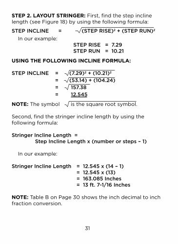
STEP 2. LAYOUT STRINGER: First, find the step incline length(seeFigure18)byusingthefollowingformula:
STEP INCLINE = (STEP RISE)2 + (STEP RUN)2
Inourexample: STEP RISE = 7.29 STEP RUN = 10.21
USING THE FOLLOWING INCLINE FORMULA:
STEP INCLINE = (7.29)2 + (10.21)2
= (53.14) + (104.24) = 157.38 = 12.545
NOTE: The symbol is the square root symbol.
Second, find the stringer incline length by using the following formula:
Stringer Incline Length = Step Incline Length x (number or steps – 1)
Inourexample:
Stringer Incline Length = 12.545 x (14 – 1) = 12.545 x (13) = 163.085 Inches = 13 ft. 7-1/16 Inches
NOTE:TableBonPage30showstheinchdecimaltoinchfraction conversion.
32
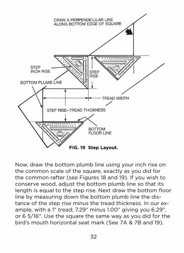
Now, draw the bottom plumb line using your inch rise on thecommonscaleofthesquare,exactlyasyoudidforthecommonrafter(seeFigures18and19).Ifyouwishtoconserve wood, adjust the bottom plumb line so that its lengthisequaltothesteprise.Nextdrawthebottomfloorline by measuring down the bottom plumb line the dis-tanceofthestepriseminusthetreadthickness.Inourex-ample,witha1"tread;7.29"minus1.00"givingyou6.29",or65/16".Usethesquarethesamewayasyoudidforthebird’smouthhorizontalseatmark(See7A&7Band19).
FIG. 19 Step Layout.

33
Theoutsidestepcornersshouldnowbemarkedoff(againseeFigure18).Startingfromthebottomplumbline,mea-sure up along the top edge of the stringer the distance of a step incline. Repeat this for each step corner, until you’ve reached the stringer incline length. Make another step incline mark for a top plumb line.
Now draw the riser plumb lines for all the steps, using the square as you did for the bottom plumb line. Finally, draw a top plumb line. Using the same procedure as you did for the bottom floor line, draw all the step tread lines (seeFigure19).Besuretomeasuredowntheriserplumbline the distance of the step rise only. Make the last tread line which will be the top floor line. If the stringer is to go below the top floor boards, add the floor board thickness to the step rise when measuring down the top plumb line todrawthetopfloorline(thisistobedonewhenthebottom floor line was found by not taking into account the tread thickness). If the tread thickness was used, add the difference between the floor board thickness and the tread thickness.
STEP 3. CUTTING STRINGER PATTERN: The stringer patternshouldbereadytocut,exceptforanyspecialal-lowances for anchoring the top of the stringer. Once that is laid out, you may want to clamp both stringers together before cutting to be sure the stringers are identical.

34
TABLE B
Change Decimals to Fractions
.06" =1/16" .56" =9/16"
.13" =1/8" .63" =5/8"
.19" =3/16" .69" =11/16"
.25" =1/4" .75" =3/4"
.31" =5/16" .81" =13/16"
.38" =3/8" .88" =7/8"
.44" =7/16" .94"=15/16"
.50" =1/2"
SOLAR PANEL SUPPORT EXAMPLELet us build a rafter support for a series of flat plate collectorsonasouth-facing8-inchriseroof.
STEP 1. RAFTER CALCULATIONS: The pitch for the support rafters, which is really the desired tilt angle for the solar panels, will be needed. If known in degrees, convert it to the nearest inch rise so that the tables may beused.Thispitchisfoundbyadding10to15degreestoyourlatitude(sincethisistheoreticallythebestforheating).Inourexample,weneeda58°pitchora19inchrisebecausethelatitudeofMilwaukeeis43°.(SeeTable C, page 39). The angle of tilt is not critical, since the efficiency is not appreciably reduced by a small dif-ference in tilt angle from optimum, thus the closest inch risecanbeused(seeFigures20and21).

35
FIG. 20 A Rafter Support Structure for Solar Panels.
Now find the support rafter rise and run by using the tables somewhat in reverse from the way you have done so far. First find the proper table for your support rafter inch rise and locate your length under the common rafter lengthcolumn(note:youmayhavetorefertoboththeRun(ft.)columnplustheRun(inch)columninreferringtothecorrectlength).Inourexampleweneeda50"or4'2"

36
support rafter length. To begin with, we find a 2' run having a3'9"length.Thisthenleavesa5"lengthwhichresultsinanapproximationofa2-11/16"run.Ifneeded,approximat-ing can be done with the following equation, if desired:
Lm – Ll ( Rh x ( ) ) + Rl Lh – LmRm = Lm – Ll 1.00 + ( ) Lh – LmWhere R = run, L = length, l = low, m = middle, h = high.
Inourexample: 5.00 – 4.63 ( 3.00 x ( ) ) + 2.50 5.63 – 5.00 Rm = 5.00 – 4.63 1.00 + ( ) 5.63 – 5.00 = 2.69 = 2-11/16"
Thuswehaveforthesupportrafterrun,2'plus211/16"equalling2'2-11/16"(or26.69").Nowtofindthesupportrafter rise: Inch Rise x Run (in.)SUPPORT RAFTER RISE (in.) = 12 19 inch rise x 26.69" = 12 = 42.25"Converted to feet: = 3' 6-1/4"
Nextweneedtofindthehorizontaloverhanglength (seeFigure21).ItisfoundbyfindingtheroofrunbetweenpointsAandBandthen subtracting the support rafter run

37
FIG. 21 Rafter Layout For A Solar Panel.
and the front overhang rafter thickness. The roof run betweenpointsAandBisfoundby:
ROOF RISE (in.) x 12 ROOF RUN (in.) = INCH RISE
42.25" x 12 = 8 inch rise = 63.37" = 5' 3-3/8"

38
From this we can get the overhang rafter length, noting thatweareusing2x6raftersgivingathicknessof1-1/2":
ROOF RUN BETWEEN A & B – SUPPORT RAFTER RUN – FRONT OVERHANG THICKNESS = OVERHANG RAFTER LENGTH 63.37" – 26.69" – 1.50" = 35.18" or in feet: = 2' 11 3/16"
Lastly we need to find the pitched rafter length, the rafter abovethehorizontaloverhangrafter.Inourexample,thepitchedrafterlengthwillequalthesupportrafterlength(i.e.,50").
STEP 2. RAFTER LAYOUTS: The support rafter bottom cut layout(atpointAonFigure21)willbemadesimilartoapitcheddooroverhang.Drapethesquare“T”overthetop(oroutside) edge of the support rafter and hold the square firmly against the rafter. Then make a mark, using the angle scale, nexttotheanglethatisfoundbysubtractingtheroofpitchangle(theroofinchriseindegrees)fromthesupportrafterinchriseangle.Inourexample,wehave573/4°(forthe19inchrisesupport)minus333/4°(forthe8inchriseroof)or24°.From this mark, draw a line to the pivot point and you will then have the bottom cut layout. The support rafter top cut layout (atpointDinFigure21)issimilartothebird’smouthlayout.First measure up the outside of the rafter the rafter length from the bottom cut and then draw a plumb line using the sup-port rafter inch rise. Now, instead of measuring down the seat depth, measure down the overhang rafter width and make a horizontal line going to the roof edge of the rafter.The horizontal overhang rafter layout is identical to the layout foraflatroofextension(henceitsname).

39
Thepitchedraftertopcutlayout(atpointCinFigure21)isthesameasthesupportrafterbottomcutlayout(atpointA).Forthepitchedrafterbottomcutlayout(atpointD)the following equation is used:
BOTTOM ANGLE = SUPPORT ANGLE + ( 2 x ROOF ANGLE ) – 90°In our example: = 57 3/4° + (2 x 33 3/4°) – 90° = 35 1/4°Use this equation when the pitched rafter length equals the support rafter length. We then hold the square tight against the top edge of the rafter as we did for the top cut and make amarkatthebottomcutangle(e.g.,at351/4°).Alinefromthis mark to the pivot point gives us the necessary bottom cut pattern.
STEP 3. RAFTER PATTERN CUTS:IfFigures20and21arecarefully studied, the rafter pattern cuts can be easily made followingthepatternsthatwerelaidout.Setyoursawat90°for all the cuts.
TABLE CLatitudes for Selected CitiesCity, State Latitude N°
Atlanta,GA 34Bismarck,ND 47Boston,MA 42Brownsville,TX 26Caribou,ME 47Columbus,OH 40Fresno, CA 37Indianapolis,IN 40Las Vegas, NV 36
City, State Latitude N°
Lincoln,NE 41Medford, OR 42Milwaukee, WI 43Nashville, TN 36OklahomaCity,OK 35Raleigh, NC 36Salt Lake City, UT 41Tallahassee,FL 30Toronto, Canada 44

40

41

42

43

44

45

46
47

48

49

50
51

52

53

54

55

56

57

58

59

60

61

62

63

64
For additional copies of this instruction manual go to www.johnsonlevel.com
The manufacturer of this product is not responsible for any errors or omissions that may occur in the production of this reference guide.

NEW Continuous Scribing Notches–Ideal for Ripping at 3-1/2" and 5-1/2".
¡Nuevo!Bordes continuos con muescaspara marcaciones idealespara efectuar cortesa 3-1/2" y 5-1/2".
RAS-17"18cm
Made in USA Hecho en EE.UU.Patents Pending Patentes Pendientes
©2012 Johnson Level & Tool Mfg. Co., Inc.Mequon, WI 53092
Montréal, Québec, Canadawww.johnsonlevel.com
7" Professional Aluminum Rafter Angle Squarewith Rafter Square Instruction Book and Tables
Escuadra Profesional de 7"para Ángulos de Vigascon manual de instrucciones y tablas paraenvigado incluidos
MARKING EDGEBorde para marcado
TOP CUTS/HIP & VALLEY
RAFTER SCALEEscala para cortes
superiores y cortes enángulo estilos Hip y Valley
COMMON RAFTER SCALEEscala común para ángulos de vigas
DEGREE SCALE/PROTRACTOREscala degrados/transportador
“T”-BAR(FOOT)Base paraángulorecto
1/4" SCALE(1" TO 3-1/2")Escala de 1/4"(entre 1" y3-1/2")
PIVOTPivote
SCRIBING NOTCHES (1" TO 5-1/2")Muescas para marcaciones (entre 1" y 5-1/2")
RAFTER SEAT CUTIndicación para corte de asiento
Johnny Square®