
Job Opportunites for Youth - JOY · methodologies for simple and small community-level...
68
Transcript of Job Opportunites for Youth - JOY · methodologies for simple and small community-level...


Job
Opp
ortu
nite
s fo
r You
th -
JOY

Tech
nica
l Gui
delin
es fo
r Sup
ervi
sors

Job
Opp
ortu
nite
s fo
r You
th -
JOY
iv

Tech
nica
l Gui
delin
es fo
r Sup
ervi
sors
v

Job
Opp
ortu
nite
s fo
r You
th -
JOY
vi

Tech
nica
l Gui
delin
es fo
r Sup
ervi
sors
vii

Job
Opp
ortu
nite
s fo
r You
th -
JOY
viii

Tech
nica
l Gui
delin
es fo
r Sup
ervi
sors
ix

Job
Opp
ortu
nite
s fo
r You
th -
JOY
x

Tech
nica
l Gui
delin
es fo
r Sup
ervi
sors
xi

Job
Opp
ortu
nite
s fo
r You
th -
JOY
xii

Tech
nica
l Gui
delin
es fo
r Sup
ervi
sors
xiii
Job
Opp
ortu
nite
s fo
r You
th -
JOY
xiv

Tech
nica
l Gui
delin
es fo
r Sup
ervi
sors
xv

Job
Opp
ortu
nite
s fo
r You
th -
JOY
xvi

Tech
nica
l Gui
delin
es fo
r Sup
ervi
sors
xvii

Job
Opp
ortu
nite
s fo
r You
th -
JOY
xviii

1
Tech
nica
l Gui
delin
es fo
r Sup
ervi
sors
IntroductionChapter
1
ILO’s Program Job Opportunities for Youth (JOY) in East Java seeks to improve employment opportunities for youth. Its objective is to create income earning opportunities for young women and men in Indonesia, through complementing national policies and local initiatives that lead to more employment intensive growth.
One component of the program, the Local Economic Development component (LED) seeks to identify and maximize the economic potentials of the two districts where the project is implemented. Within its scope of activities and as per the project document, the LED process includes the promotion of employment intensive (also referred to as labour-based) infrastructure investments.
Through JOY, the ILO provided technical assistance in March-April 2009 to the local government and the Public Works Department of Malang in enhancing their understanding and capacities about the application of labour-based (LB) methodologies for simple and small community-level infrastructure development.
This was done through the delivery of basic orientation and training course on the application of LB approaches and technologies within the context of the Gotong Royong initiative in Malang. The training was delivered to technical staff of the district Public Works Department (PWD), community supervisors and key Government staff of the District and selected sub-Districts.
The objective of the Gotong Royong initiative in Malang is to make an optimum use of locally available labour and materials and to accelerate village infrastructure development. The initiative, that started in 2003 and applies labour-based methods, also aims at revitalizing the currently fading Gotong Royong spirit among the Indonesian people. Communities, through the village administration, can request the Malang Kabupaten for a Gotong Royong partnership project, under the condition that the community is ready to provide local materials, labour and the land necessary to undertake the proposed initiative.
Activities under the Gotong Royong initiative are implemented in various sectors, with the majority of efforts directed to the improvement of rural roads. Until 2009, the PWD in Malang had channeled about 80 billion Rupiah (about 8 million USD) to fi nance partnership program between communities and the district government to develop rural infrastructure. The partnership program has covered 1,141 villages throughout the Malang Regency. The total community contribution under the partnership program is about 176 billion rupiah (17.6 million USD) and the total cost of all implemented projects is almost 256 billion Rupiah (25.6 million USD).

2
Job
Opp
ortu
nite
s fo
r You
th -
JOY
Following the initial support provided by the ILO JOY Project in 2009, the PWD Malang has requested ILO to provide follow-up support. The particular request was to provide assistance in developing a practical technical manual covering the various design and implementation aspects of rural road development, using labour-based approaches and technologies. Intended users include District-level PW supervisors and community-based supervisors involved in the construction, rehabilitation and maintenance of low volume rural road infrastructure.
The PW Department in Malang had already prepared a fi rst working draft and requested the JOY Project to review this manual and provide technical assistance to improve its quality. The outcome of the technical assistance provided through the ILO JOY project is the current manual.
The purpose of the current guideline is to provide technical guidance to community-based supervisors and PWD supervisors in the design, construction, rehabilitation and maintenance of low-volume rural roads that are implemented under the Gotong Royong initiative. The guide can also be used by professional PWD trainers to provide training to supervisors.
Skilled and knowledgeable supervisors are KEY in ensuring that projects are being constructed as per required design standards and specifi cations. This manual aims at providing supervisors with the skills and knowledge required for the effective supervision of rural roads development and maintenance works. This will ensure an optimum return to the investments made and a maximum life-time of the constructed infrastructure assets.
The scope of this manual is to provide supervisors with guidelines that will enable them to check whether basic conditions and requirements of rural road design, construction and maintenance are being adhered to. Depending on the scope of work, the design and construction of rural roads may include complex engineering work. This means that the availability of suffi cient adequate engineering capacity will be required. Without such professional engineering inputs it will not be possible to ensure quality control in the design, construction and maintenance of rural roads and this will negatively affect the quality, durability and thus the life-time of the created infrastructure assets.
Experiences with community-based local infrastructure development initiatives indicate that adequate engineering inputs are required for the design and construction of more complex work.. Normally the involvement of the local communities is limited to operations like clearing and earthwork moving operations. It is therefore extremely important that professional inputs are secured for more complex operations like sealing of the road surface and the construction of bridges, culverts and other drainage structures and retaining walls. The current manual covers a wide range of aspects related to the design and construction of rural roads. The introduction of these aspects will enable the supervisors to understand the complexity of certain operations and the need to secure professional expertise.
The manual lends itself very well to be used as a guide for trainers who are involved in the training of supervisors. Various illustrations and photos are included that facilitate the use of the manual. The workshops that were conducted for community-based supervisors revealed that the supervisors indeed require extensive training to enable them to carry out supervision in an effective way.

3
Tech
nica
l Gui
delin
es fo
r Sup
ervi
sors
Gotong Royong Initiative in Malang
Chapter
2
The Malang Regency Partnership Program, also called the Gotong Royong Initiative is implemented in Malang Regency in East Java Province of Indonesia. Local communities and responsible line agencies like the Department of Public Works (Bina Marga) are actively involved in this Partnership Program in which they are working together.
The Malang Partnership Program is an innovative initiative that has attracted a lot of interest from the local communities who have demonstrated their willingness and readiness over the last seven years to participate pro-actively in the program. The program aims at developing and improving local infrastructure and builds on the traditional Gotong Royong system of providing mutual assistance. Under Gotong Royong communities undertake voluntary work or provide in-kind contributions or land for activities that contribute to the development of public infrastructure in the community.
The main emphasis of the Partnership Program in Malang is on the development, improvement and maintenance of community infrastructure, with a special emphasis on low-volume roads. Various projects like PNPM Mandiri IP and PNPM Mandiri Perdesaan participate in the initiative.
Programs like the Government Partnership Program in Malang can be very effective for the development, improvement and maintenance of small and simple community-level infrastructure like low-volume rural roads. This is particularly the case if the local communities are willing to provide self-help labour and other voluntary inputs on a sustainable basis to address local development constraints that they consider priorities.
Another condition is the need to have a suffi cient large reservoir of available labour. Strong social cohesion, active support from local leaders, a local sense of ownership and a pro-active attitude among communities are also important factors that increase the chance of success.
It appears that all above conditions are met within the Malang Partnership Program and the program could possible by considered at some stage for duplication in other parts of Indonesia. What needs to be given more attention however is an improvement of the quality of the work. The current shortcomings in this respect have been recognized by the PWD of Malang and that is the reason why the current manual has been developed.
The manual aims to provide the supervisors of PWD and of the Community Development Committee with guidelines that will assist them in maintaining the

4
Job
Opp
ortu
nite
s fo
r You
th -
JOY
required quality standards for relatively small and simple infrastructure. These works should be within the (potential) capacity of the local communities. Depending on the types of work to be undertaken, technical support from the PWD may be required. Considering the scope of work undertaken and the local conditions, the guideline promotes the use of labour-based approaches and technologies. Such approaches require a particular organization and management of the labour-force and these aspects are also included in the manual.
The philosophy of the Malang Partnership Program is that the communities become the main actors of development. They are involved throughout the project cycle, i.e. from planning and programming to implementation and maintenance.
Six steps can be distinguished in the implementation of the Partnership Program. These are shown in fi gure 1.
Figure 1: Steps in Implementation of Partnership Program
Formulation Proposal
2
Preparatory Works
1
Submission Proposal
3
Selection Village
Proposal
4
Undertake the construction
works
5
PARTNERSHIP PROGRAM
FORRURAL ROAD
DEVELOPMENT
Post construction
works
6
� Preparatory Works: The Community with guidance from the Village Head, establishes a Village Development Commitee (PPD). The PPD will be responsible for the development planning of the village. The PPD formulates the priority development activities to improve the condition in the village, especially in term of infrastructure requirements.
Formulation of Proposal: The PPD prepares the simple proposal for the village development plan. The Partnership Program requires a community contribution
1
2

5
Tech
nica
l Gui
delin
es fo
r Sup
ervi
sors
in cash of at east 40% of the total cost of the proposed project. That pre-condition is a key criteria for PWD to decide whether the project proposal will be approved. Another key criteria for PWD is the availability of suffi cient funds under its local annual budget to provide the Government contribution. If these conditions are met, PWD will invite the PPD to complete and submit the proposal.
Submission Proposal: The PPD, through the Village Head, submits the partnership proposal to the Bina Marga Rural Road Facilitation Section of PWD at District level. An example of the format used for the submission of proposals is presented in Annex 1.
Selection Village Proposal: After PWD has verifi ed that the requesting community will provide the required community contribution, PWD will check the design, specifi cations and cost-estimates of the submitted proposals. If the proposal complies with the district budget standards for rural roads, PWD will verify whether suffi cient funds are available in the District Annual Budget (APBD). If this is the case the next step takes place.
The Construction Phase: PWD and the PPD will enter into a Partnership Agreement once the proposed project has been approved. In principle the PPD will be responsible for undertaking and managing the civil works. During the construction phase, the PWD will supervise the activities regularly and provide necessary technical support through the responsible PWD staff at sub district level (Kecamatan).
Post Construction Phase: After the construction phase, the community is responsible for the maintenance of the infrastructures. The community has to fi nance the maintenance operations and has to decide on how to fi nance and organize the maintenance. The PPD can for example facilitate the establishment of a village Operation and Maintenance Committee (KPP) and provide support in the formulation of O&M plans.
3
4
5
6

6
Job
Opp
ortu
nite
s fo
r You
th -
JOY

7
Tech
nica
l Gui
delin
es fo
r Sup
ervi
sors
Surveys, Designs and Cost Estimates
Chapter
3
Survey Activities include the following:
1. Preliminary rough topographical survey to select the best alignment;
2. Survey of catchment area to determine the need for bridges and culverts;
3. Check adequacy of (sub-)soils, quarry materials and other local materials;
4. Detailed survey to determine design and to estimate work quantities.
General Survey Guidelines are summarized below:
The selection of the correct alignment is the most import part of the design, especially for new roads. If the wrong alignment is chosen, this may lead to very high costs, erosion and technical construction problems.
Try to avoid alignments with drainage problems or that require excessive (earth) work.
Check whether there are issues related to land acquisition.
Identify locations along the road where bridges and culverts will be required to ensure a safe passage of water away from the road;
Check which constructions materials are locally available. The availability of local construction materials may be a factor in deciding on the preferred design option.
3.1 Surveys
Survey activities
General survey guidelines
8
Job
Opp
ortu
nite
s fo
r You
th -
JOY
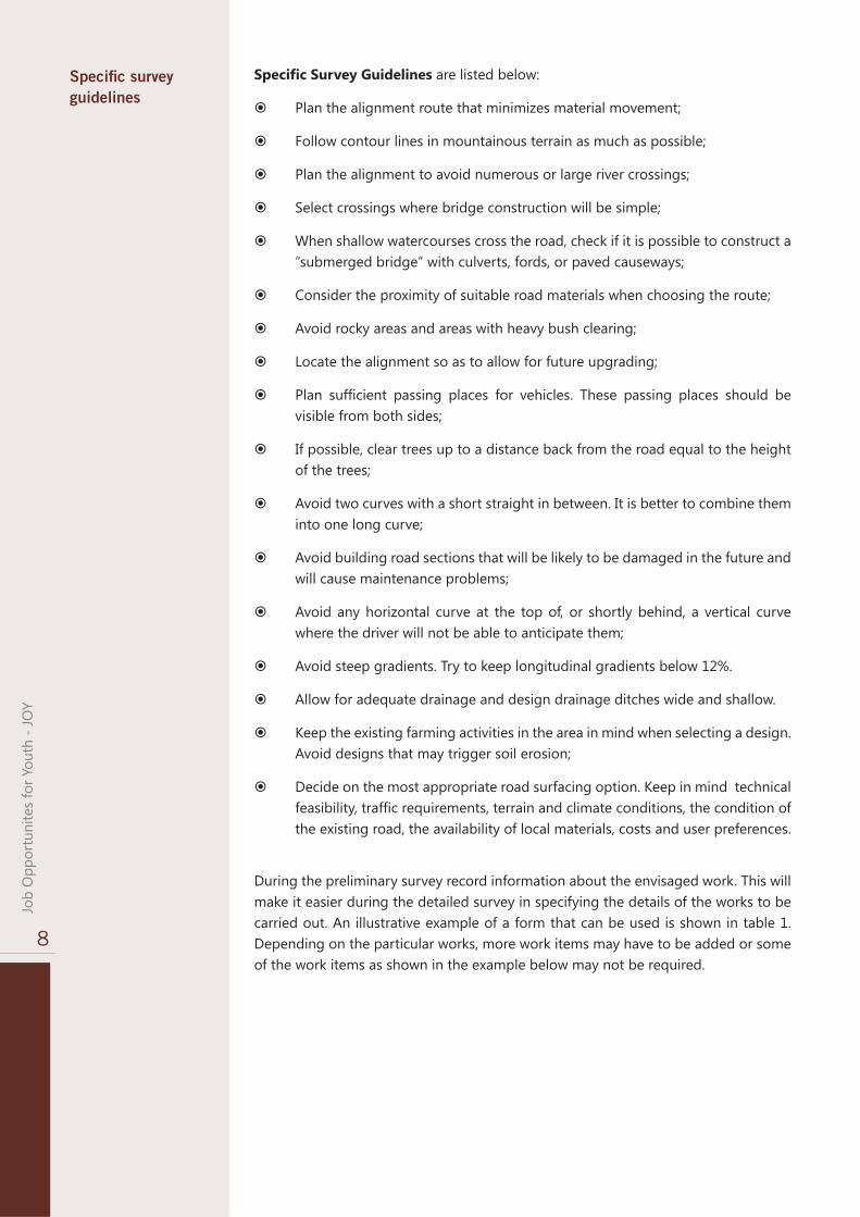
Specifi c Survey Guidelines are listed below:
Plan the alignment route that minimizes material movement;
Follow contour lines in mountainous terrain as much as possible;
Plan the alignment to avoid numerous or large river crossings;
Select crossings where bridge construction will be simple;
When shallow watercourses cross the road, check if it is possible to construct a “submerged bridge” with culverts, fords, or paved causeways;
Consider the proximity of suitable road materials when choosing the route;
Avoid rocky areas and areas with heavy bush clearing;
Locate the alignment so as to allow for future upgrading;
Plan suffi cient passing places for vehicles. These passing places should be visible from both sides;
If possible, clear trees up to a distance back from the road equal to the height of the trees;
Avoid two curves with a short straight in between. It is better to combine them into one long curve;
Avoid building road sections that will be likely to be damaged in the future and will cause maintenance problems;
Avoid any horizontal curve at the top of, or shortly behind, a vertical curve where the driver will not be able to anticipate them;
Avoid steep gradients. Try to keep longitudinal gradients below 12%.
Allow for adequate drainage and design drainage ditches wide and shallow.
Keep the existing farming activities in the area in mind when selecting a design. Avoid designs that may trigger soil erosion;
Decide on the most appropriate road surfacing option. Keep in mind technical feasibility, traffi c requirements, terrain and climate conditions, the condition of the existing road, the availability of local materials, costs and user preferences.
Specifi c survey guidelines
During the preliminary survey record information about the envisaged work. This will make it easier during the detailed survey in specifying the details of the works to be carried out. An illustrative example of a form that can be used is shown in table 1. Depending on the particular works, more work items may have to be added or some of the work items as shown in the example below may not be required.

9
Tech
nica
l Gui
delin
es fo
r Sup
ervi
sors
Table 1: Example of Preliminary Road Works Inventory Record
3.2 Design
Steps in the design process include the following:
1. Establish the type of road (e.g. district road, rural road, urban road);
2. Assess the traffi c requirements;
3. Assess other factors that affect the design choice (like terrain, type of soils and their strength, availability and cost of construction materials, etc.);
4. Select geometric design standards (like road cross-section, design speed);
5. Select appropriate pavement design;
6. Assess the need for road structures (bridges, culverts, retaining walls, etc);
7. Assess the availability of labour and their skills;
In mountainous areas it is often not practical or too expensive to maintain high design standards like small numbers of curves or soft road gradients, as this would involve considerable earth movement and lead to very high costs.
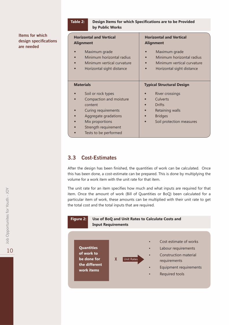
Table 2 provides an illustrative example of design items for which design specifi cations are needed. These are normally provided by technical line ministries like the Public Works Department.
During the preliminary survey record infor-
mation of work to be done
Steps in the design process
Road name District Sub-District Inventory done by: Date:
Works
Chainage (meter) 0-100 100-
200 200-300
300-400
400-500
500-600
etc
1
Clearing Left Right
2 Base reconstruction 3 Base repair 4 Earthwork cut 5 Earthwork fill 6 Construction embankment 7 Side drains Left
Right 8 Mitre drains Left At 25m At
225m At
400m
Right 9 Culvert Location At
150m At
330m At
400m
diameter 600mm 600mm 600mm
10 Drift Location At 245m
Length 10m
11 Bridge Location At 390m
Length 8m
12 Etc.
10
Job
Opp
ortu
nite
s fo
r You
th -
JOY
Items for which design specifi cations are needed
Horizontal and Vertical Alignment
Maximum grade Minimum horizontal radius Minimum vertical curvature Horizontal sight distance
Horizontal and Vertical Alignment
Maximum grade Minimum horizontal radius Minimum vertical curvature Horizontal sight distance
Materials
Soil or rock types Compaction and moisture
content Curing requirements Aggregate gradations Mix proportions Strength requirement Tests to be performed
Typical Structural Design
River crossings Culverts Drifts Retaining walls Bridges Soil protection measures
3.3 Cost-Estimates
After the design has been fi nished, the quantities of work can be calculated. Once this has been done, a cost-estimate can be prepared. This is done by multiplying the volume for a work item with the unit rate for that item.
The unit rate for an item specifi es how much and what inputs are required for that item. Once the amount of work (Bill of Quantities or BoQ) been calculated for a particular item of work, these amounts can be multiplied with their unit rate to get the total cost and the total inputs that are required.
Figure 2: Use of BoQ and Unit Rates to Calculate Costs and Input Requirements
• Cost estimate of works
• Labour requirements
• Construction material requirements
• Equipment requirements
• Required tools
Quantities of work to be done for the different work items
Unit RatesX
Table 2: Design Items for which Specifi cations are to be Provided by Public Works

11
Tech
nica
l Gui
delin
es fo
r Sup
ervi
sors
The section below outlines, based on an example, how cost estimates (budgets) and input requirements can be calculated. Costs include the costs of materials, labour, equipment, tools and other inputs required for the construction works (and possibly also for preparatory works). As prices for labour, materials, equipment (rental) and other inputs may differ from region to region, the costs for one unit of a particular work item may vary between different regions.
In the preparation of the budget, fi ve steps have to be followed. These steps are summarized in fi gure 3 and are described below.
STEP 1STEP 2
`
Formulate BoQ
1. Calculate Volume of Each Ac�vi�es
2. Establish Bill of Quan�ty (BoQ)
STEP 3
`
Unit Price Analysis
1. Labor Requirement
2. Material Requirement
3. Equipment Requirement
STEP 4
`
Calculate Total Project Cost
1. Compile BoQ
2. Compile Unit Price
3. Calculate total budget/project cost
STEP 5
`
Breakdown Task/Works
1. Design & Spec.
2. Detail Drawing
3. Breakdown Task/Work
`
Informa�on Gathering
1. Labor Price
2. Material Price
3. Equipment Price
4. Calculate the Price for Each Ac�vi�es/Task/Works
Step 1: Preparatory activities include the collection of information regarding the design and specifi cations, the engineering drawings and the breakdown of the construction works into the specifi c items of work and their task. With this information it will be possible to identify the different items of works that have to be implemented and the volumes of work for each of these work items. Annex 2 provides information on how to calculate areas, volumes and weight of commonly used construction materials. A number of examples are also provided in annex 3.
Step 2: Information about costs: Gather information about the costs of materials, labour, equipment and other inputs required for the different works that have to be undertaken. These prices are obtained in the market and provide the so called List of Materials Unit Price and the Wage Unit Price List. In the same way the costs for securing other inputs like for example the hiring costs of equipment can be obtained.
Step 3: Calculate volumes of work: This can be done based on the information listed under step 1. This results in the so called Bill of Quantities (BoQ). The BoQ is normally prepared by the Public Works Department. It includes for each and every of the work items (and their activities) the volumes of inputs that are required.
Step 4: Calculate the unit rates for every item of work: This is done with the information collected under step 2. This procedure is called the unit rate analysis and is normally carried out by the Public Works Department.
Step 5: Calculate the total cost estimate of the works: With the information about the unit rates and the BoQ it is possible to calculate the total costs of the works.
Figure 3: Steps in the Preparation of Budgets

12
Job
Opp
ortu
nite
s fo
r You
th -
JOY
An illustrative example of a completed cost estimate is presented in table 3. This examples shows how the costs for 1 kilometer of Double Bituminous Surface Treatment (DBST) can be calculated. The fi rst column shows the work-norms for labour. This is also called the labour productivity norm. It shows how much work can be done by one labourer in one day.
Take for example the work item Site Clearing. In the example of table 3 it is seen that one labourer can do 60 m2 of clearing in one day. In the example the cost of 1 m2 of clearing is Rupiah 800. In the example 3,000 m2 of site clearing is required for 1 km of DBST and the total cost for site clearing is Rupiah 2.4 million. Table 3 also shows that the number of labour-days required for site clearing is 50. The number of labour-days is calculated by dividing the total quantity of work required (i.e. 3,000 m2) by the work norm (or labour productivity) for site clearing (i.e. 60 m2 per labour-day).
It should be noted that the information presented in table 3 only serves the purpose of giving an example. Actual work norms, quantities of work required and unit costs will vary, depending on the specifi c requirements.
In Indonesia the Indonesian National Standard (Standar Nasional Indonesia=SNI) for civil works is used to determine labour, material and equipment requirements for construction activities.
Example of calculating the cost of 1 km of DBST pavement
Table 3: Illustrative example of calculating a cost estimate for one kilometer of DBST
13
Tech
nica
l Gui
delin
es fo
r Sup
ervi
sors
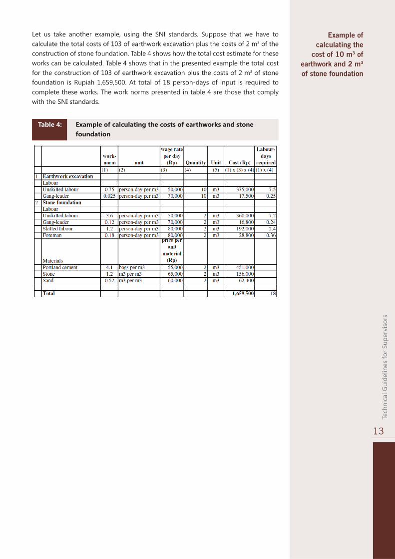
Let us take another example, using the SNI standards. Suppose that we have to calculate the total costs of 103 of earthwork excavation plus the costs of 2 m3 of the construction of stone foundation. Table 4 shows how the total cost estimate for these works can be calculated. Table 4 shows that in the presented example the total cost for the construction of 103 of earthwork excavation plus the costs of 2 m3 of stone foundation is Rupiah 1,659,500. At total of 18 person-days of input is required to complete these works. The work norms presented in table 4 are those that comply with the SNI standards.
Example of calculating the
cost of 10 m3 of earthwork and 2 m3
of stone foundation
Table 4: Example of calculating the costs of earthworks and stone foundation

14
Job
Opp
ortu
nite
s fo
r You
th -
JOY

15
Tech
nica
l Gui
delin
es fo
r Sup
ervi
sors
Tools and Equipment Chapter
4
4.1 Hand Tools
Hand tool requirements depend on the size of the project, soil types, terrain and the type of works that are planned. Tools that are normally being used are listed in table 5. The table also indicates how much of each of the tools would be required for a workforce of 25 labourers.
Table 5: Tool Requirements for Typical Labour-based Road Construction
Tool
Profi le Board and Ranging Rod30 m and 3/5 m measuring tapeLine level, nylon string
Hoe, shovel, spadesPickaxe and crowbarBush-knife, axe, bow-saw RakeWheelbarrowHand rammers
Bucket, watering canSledge hammer
ChiselPegs
Use
Survey, setting out and for measurementSurvey, setting out and for measurementSurvey, setting out and for measurementFor all types of earthworksExcavation in hard materialsClearing and grubbing vegetation
Spreading material Transporting materialsCompacting diffi cult accessible small areasVarious use, includes wateringVarious use, including hammering in pegsVarious use, e.g. making holes for pegsFor setting out of work
Quantity
At least 5
At least 1 set
At least 1 set
One per labourerDepends on needsDepends on needs
At least 55-10At least 5
Depends on needsAt least 2
At least 2Depends on needs
Good quality tools increase productivity and the quality of the work. Tools used in agricultural works are often not strong enough for use in road construction.
Tools for earthwork activities are crowbars, pickaxes, bush knifes, hoes, shovels, spades, hand rammers and wheelbarrows.
Crowbars should be 1.5 to 1.8 meters long, are made of steel and should have one pointed and one chisel end.
Typical hand tool requirements for a labour force of 25
workers
Quality tools are needed to produce
quality work

16
Job
Opp
ortu
nite
s fo
r You
th -
JOY
Hand rammers are used for compacting small areas that are out of reach of mechanical compaction equipment (e.g. around abutments of structures). Hand rammers should weight 6-8 kg, should have a suffi ciently long handle and the diameter of the bottom end should be 13-15 centimeter. They can be made of solid wood, steel or concrete.
Wheelbarrows are used for the transport of construction material such as soil, sand, aggregate, stone, concrete etc. over distances up to 200 meters. A good wheelbarrow should take a big load (60 to 70 liters) and be easy to balance and tip.
Survey tools are also essential for survey work. Without them works cannot be set out correctly and this will negatively affect the quality of the work. The section below describes the different tools used for setting out work.
A Line Level is a short spirit level (about 100mm long) with a hook at each end to hang it from a smooth nylon string. It can be used to transfer the level of one location to another point and to set out gradients of not less than 1: in 300. Its range is up to 50 meters. It needs 2 people to operate it.
Figure 4 shows how to use the line level to transfer a level. Place the spirit level half-way between two ranging rods. Keep the string line tight – do not let it sag. The line operator moves the string up or down until the bubble is centered in the middle between the spirit level marks. The string line will then indicate the horizontal line.
Transfer levels or setting out gradients with a line level
Figure 4: Procedure to Transfer Levels from One Location to the Other
How to check the accuracy of the spirit level:
1. Place two ranging rods 10m apart and fi x a line on one rod;
2. Transfer the level to the other rod and mark this level;
3. Keep the line in place and turn the level;
4. Adjust the line again and mark the new level;
5. Measure the different between the two levels;
6. If the difference is less than 10cm, the level works correct, if not replace the level
Procedure for checking the accuracy of a spirit level

17
Tech
nica
l Gui
delin
es fo
r Sup
ervi
sors
Ranging Rods and profi le boards are used to set out works and to calculate volumes of earthworks. Ranging rods are made of hollow metal tube (20 – 25mm diameter galvanized water pipes) with a pointed end of reinforcement steel. Standard they are 2 meters long and painted alternately red and white to make them easy to see during setting out. The length of red
and white sections is 250mm.
Profi le boards are used to set out the road profi le. A profi le board can slide up and down a ranging rod and can be fi xed to it at any point with a screw. A profi le board is usually made
from thin steel plate welded to a short length of metal tube that can slide up and down and clamped to the ranging rod.
A useful size for a profi le board is 40 x 12cm, painted red.
Measuring tapes of 30 meter and 3m or 5m are used for setting out. The tapes are made of steel or linen. Keep the tapes
clean and avoid dirt from entering the housing.
Pointed Chisels or Metal Spikes are octagonal or round steel rods with one pointed end. The minimum diameter is 20mm and the length should be 30 – 40cm. They should be very strong. They are used with hammers to make holes for ranging rods or pegs in hard/compact soils.
Pegs are made of wood or bamboo and are ≈ 40cm long. The chainage of the road where the peg is put, is marked on the peg with waterproof marker.
Figure 5: Procedure to Check the Accuracy of the Spirit Level
<---------------------- 10 meter ------------------------->

18
Job
Opp
ortu
nite
s fo
r You
th -
JOY
4.2 Equipment
Commonly used equipment:
Tractors and trailers;
smooth-wheeled pedestrian or sit-on vibratory rollers of 0.8 – 1.7 ton;
Water bowsers;
Tractor-towed graders;
Concrete mixers;
Bitumen sprayers.
Equipment needs to be regularly inspected and maintained. Operators need to know maintenance and service requirements of the equipment. Typical daily checking, cleaning and maintenance activities for equipment are listed in table 6.
Commonly used equipment
Maintain equipment
Picture 1: cleaning of emulsion sprayer after use
Table 6: Daily Maintenance Activities to be Carried-out for Equipment
Daily Checks for Equipment
Oil levels lubrication, hydraulics and transmission
Brake and clutch fl uid level
Hydraulic hoses and couplings
Radiator water level
Grease nipples/tracks
Battery connections and battery water
Connections from alternator
All V-belts and their tension
Tire pressure
Nuts and bolts

19
Tech
nica
l Gui
delin
es fo
r Sup
ervi
sors
Construction MaterialsChapter
5
Suffi cient construction materials should be available on site before starting the works. When receiving the materials on site, inspect the quantity, verify the quality and store them properly. Record received quantities in the stores ledger. Also record quantities used in the construction works.
5.1 Cement
Cement is very expensive and must be handled and stored with care. Always stack the cement bags off the fl oor and use the oldest cement fi rst. Cement is used for concrete structures. The section below explains how to prepare concrete.
Concrete should be prepared according to prescribed procedures to make sure that it reaches it required strength. Avoid under-design or over-design. An under-designed structure is weaker than desirable and is likely to fail (leading to extra costs). Over-designed structures are too strong and this results in unnecessary costs.
Mixing of concrete is called batching. Usually batching is done very close to the structure to be constructed. The site should be cleared of all vegetation and humus, and leveled out to prevent water running off during mixing.
The batching site should hold stockpiles of materials and part of the site has to be kept for concrete mixing. A batching site should be at least 4 x 6m and needs to be well compacted. If concrete is to be mixed by hand, apply a layer of cement mortar on the section set aside for mixing and leave it to harden for about 2 days before mixing begins. For batching it is very practical to use a gauge box with internal dimension of 400 mm x 300 mm x 300 mm. The volume of the box is 0.036 m3 or 36 liters, which is equivalent to the volume of one (50 kg) bag of cement (see fi gure 6).

20
Job
Opp
ortu
nite
s fo
r You
th -
JOY
The volume of the other materials is calculated proportionally for one bag of cement. One batch of concrete is a mixture of one bag of cement and the required quantities of sand and aggregate. These ratios depend on the approved mix designs. If the mix design is 1:2:4, then one bag of cement is mixed with 2 gauge boxes of sand and four gauge boxes of aggregate. This is called on one batch of concrete.
On most labour-based projects concrete for small structures is mixed by hand because the volumes of concrete involved are appropriate for hand-mixing. If large volumes of concrete need to be mixed, concrete mixers should be used.
Procedure for mixing of concrete by hand:
Place the materials in layers, starting with sand at the bottom followed by cement and then concrete stone. If more than one batch has to be mixed at a time, the same order of layers of materials shall be placed on top of the previous batch and so on.
Mix thoroughly and then add water and continue to mix until all the aggregate is coated with cement paste and the mix looks consistent. A well mixed concrete has a consistent colour and looks greasy. Make sure that the mixing process takes no more than 15 minutes from the time water is added.
Procedure for mixing concrete with concrete mixer:
Proportion the different materials using gauge boxes according to the required mix design;
Feed the materials into the concrete mixer starting with concrete stone followed by sand and cement and, fi nally, water;
Mix the concrete thoroughly for about 90 seconds.
Water is an important ingredient in concrete works. If the water is dirty, it results in weaker concrete. In general, there is no need to test the water if it looks clean. Water that looks dirty should be checked. If the intended concrete structure is no larger than a small box culvert, a trial concrete mix is suffi cient to check whether the water is suitable. For larger structures the water should be tested in laboratories.
Clean water needs to be used
Figure 6: Gauge box to control mix proportions

21
Tech
nica
l Gui
delin
es fo
r Sup
ervi
sors
After mixing, the concrete needs to be placed within 30 minutes. Often wheelbarrows are used to transport the concrete. They should be clean and without holes. Pouring of concrete should be done in layers. Concrete needs to be compacted otherwise the concrete will not reach its required strength. Compaction should be carried out until there are no air bubbles popping out on the surface of the concrete. Over-compaction should be avoided as segregation may occur. If compaction is done by hand rammers, a layer should not be thicker than 300mm. If poke vibrators are used a layer should be at most 600mm thick.
To prevent segregation, concrete should not be poured over a height of more than 1.5m under freefall. Where the depth of free fall exceeds 1.5m wooden or steel funnel chutes should be used. Concrete on all slabs or horizontal structural members should be placed in a continuous pour in order to avoid construction joints. For vertical members, construction joints should be roughened or grooved to ensure bonding between two separate pours. The top of the concrete should be fl oated to level with a trowel or metal or wooden fl oat.
Following pouring and compaction, and after the concrete has set and under-gone initial hardening, the concrete needs to be cured. Water for curing can be applied by fl ooding, wet dressing or wet sand cover or any other method as long as the concrete surfaces are kept moist Curing is very important as it will ensure that the concrete gains strength and hardness. If curing is not carried out properly then the concrete close to the surface of the structure will not harden properly. Curing should normally be carried out for at least 7 days.
For non-fl exural members, formwork may be removed after 2 days. On short span fl exural members, side shuttering may be removed after 3 days but the propping should be left in place for at least 7 days. On long span fl exural members propping should be left in place for 28 days, otherwise wide cracks may develop that will weaken the structure or the structure may actually collapse. Expansion joints in concrete slabs are required for approximately every 10 to 15 meters.
5.2 Aggregate
Aggregate is used in concrete works, in sealing the road surface, in gravel roads and as sub-base material. Fine aggregate includes pit-sand, river-sand and other similar fi ne aggregate that could be used in concrete mixes. Coarse aggregate can be crushed stone from quarries, hand-crushed stone or natural aggregate. Natural rounded river aggregate is weak if exposed to weathering. If particular aggregate size specifi cations are required, aggregate from natural gravels normally needs to be sieved. Aggregate from river gravel can be used in small to medium concrete works (i.e. those smaller than bridges).
If aggregate contains mud or organic materials, it should be washed as the strength of concrete is much less if dirty aggregate is used. To check the contamination of an aggregate, half-fi ll fi ll a transparent container (of a small diameter and with straight vertical walls) with a sample of the aggregate. Pour water into the container until it is full. Shake the contents for 5 minutes and place the container on a fl at surface. Let it stand for at least 3 hours. If the water is then still dirty, there is clay in the aggregate. In that case let the clay sediment settle for another 12 hours.
How to check whether aggregate is
clean
22
Job
Opp
ortu
nite
s fo
r You
th -
JOY
The next step is to measure the thickness of the top layers with undesirable material. Do this without disturbing the container. The thickness of the undesirable material (t ) should be not more than 5% of the total thickness of the sediment (T ). If for example the total thickness of a sample is 60cm and the thickness of the fi ne layers is 6cm, the undesirable material constitutes = (6:60) x 100% = 10% and the aggregate should be rejected.
To check the strength of the aggregate take about 200 representative aggregate particles and place them on a hard surface. Each stone is then hammered once with an ordinary claw hammer. If more than 10% of the stones crumble to fi ne particles or pulverize then the aggregate should be rejected. This method is only applicable for aggregate proposed in the construction of small structures.
River-sand is usually the best sand for use in concrete because it generally meets the grading requirements and it is usually clean. Pit-sand is often mixed with organic materials and if this is the case, it needs to be washed. Take care when using pit-sand instead of river-sand for concrete works. Where river-sand is too coarse, pit-sand can be mixed with river-sand.
5.3 Fuel, Oil, Lubricants and Bitumen
Fuel, oil, lubricants and bitumen should be stored separately, away from other supplies. Make sure that there are no open fi res nearby the store. Store fuel, oil, lubricants and bitumen in good drums that do not leak.
Aggregate with more than 5% undesirable material should be rejected
Checking the strength of aggregate for small structures
Sand for construction works

23
Tech
nica
l Gui
delin
es fo
r Sup
ervi
sors
Planning and Organization of Works
Chapter
6
6.1 Planning of Works
Before you can start with the construction activities, a planning of the work is required. This includes a plan for the required labour inputs, the procurement of construction materials and securing the necessary equipment. A normal sequence of activities that have to be carried out and for which a planning needs to be made is as follows:
Setting out of works;
Clearing of shrubs, trees, grass cover, debris, humus etc;
Excavation to level, i.e. make a level X-section on which to form the road;
Construct retaining walls;
Construct structures like culverts, bridges, drifts;
Construct drains, like side, mitre and cut-off drains, scour checks, etc;
Formation of the camber or cross-fall of the road;
Construction of the pavement, including the base and the surface;
Finishing activities like erosion protection measures, fi nal clearing, etc.
Before you can make a work plan, you need to have certain information. Without it, it will not be possible to make a realistic work plan. It is important to remember that a good and realistic work plan is always required. Without it, you will not be able to estimate how much inputs (including labour) are required and when these inputs are needed.. The absence of work plan will result in a disorganized (and unhappy) workforce and it will prevent you from achieving your targets (both in terms of quality and quantity). Information that you need to have in order to be able make a work plan includes the following:
Expected starting date and completion date of the works;
volumes and locations of the different types of work to be undertaken;
Input requirements for labour, construction materials, equipment, tools;
Availability of labour, equipment, tools and construction materials;
Information about the usual start and end of the rainy season.
Work operations that need to be
planned
Information required for
preparing a site work plan

24
Job
Opp
ortu
nite
s fo
r You
th -
JOY
Table 7 presents an illustrative example of how a work plan could look like. In this example we have assumed that a section of 1 kilometer of a road will be sealed using a Double Bituminous Surface Treatment (DBST). The information about the required inputs for this work is obtained from the example presented in table 3. Suppose that the work as shown in table 3 has to be completed in 6 months and that per month 20 days are worked. Table 7 shows the monthly planning for the required labour, material and equipment inputs. It may be necessary to break-down the planning into a weekly plan as well. The same approach can be used for making a weekly plan as for the monthly plan shown in table 7.
In making the illustrative plan as shown in table 7, the purpose was follow a logical sequence of activities and to try to balance the total required number of worker-days of inputs equally over the 6 months. Table 7 shows that every month about 10-12 workers would be required, assuming that each worker works 20 days per month (take for example month 1: row 13 shows that 230 work-days are required and if a worker works 20 days per month that means that for month 1 230/20=11.5 workers are required. This number is rounded to 12).
Table 7 also shows when the tools, materials and equipment need to be secured or procured, in line with the work plan. The preparation of a work plan like presented in table 7 will require some trying before you will get a balanced and logical work plan. The technical offi cer or engineer may assist in the preparation of the work plan.
Table 7: Illustrative example of a monthly work plan for the construction of 1 km of DBST
Month 1 Month 2 Month 3 Month 4 Month 5 Month 6 Total Labour input requirements Activity 1 Setting out 120 120 2 Site clearing 50 50 3 Preparing sub-grade 27 27 4 Cutting boxes 107 107 5 Spreading sub-base 16 80 96 6 Spreading shoulder 65 65 7 Spreading base course 140 115 255 8 Spreading chips 20 20 9 Applying coat 80 80 10 Roller operator 37 37 11 Transport material 20 40 40 100 12 Labour support 60 60 60 60 60 60 360 13 Total worker days 230 210 225 240 215 197 1,317 14 Total workers 12 11 11 12 11 10 15 Engineer-days 5 5 5 5 5 5 30 16 Technical Officer -days 10 10 10 10 10 10 60 17 Supervisor-days 20 20 20 20 20 20 120 Tools, equipment and material requirement schedule Secure tools Rent roller 1 ton Rent roller 3 tone Hire tractor + trailer Hire waterbowser Procure material base Procure sand Procure bitumen Procure chips

25
Tech
nica
l Gui
delin
es fo
r Sup
ervi
sors
Once the overall work plan has been made, the preparation for the start of the works can begin. This also includes the preparation of a more detailed site work plan that gives information on how the labourers should be organized on the site. How such a plan can be prepared, in particular regarding the organization of the labour, is explained in paragraph 6.3.
6.2 Labour Incentives
A well motivated workforce is very important for the successful implementation of the construction works. The role of the supervisor is very important in motivating the labourers. He/she can help to motivate the labourers in various ways:
Creating a feeling of achievement and showing appreciation of the work done by the labourers;
Delegating responsibilities to the labourers and instructing and training the labourers so that they can do their work well;
Organizing and managing the work in an effi cient and effective way and communicating and behaving correctly with the labourers;
Ensuring good and decent working conditions at work sites.
6.3 Organization of the Labour
The organization of the workforce at the site is very important when construction activities are being implemented using labour-based work methods. There are a number of attentions points that must be kept in mind when organizing the labour at the worksite:
Mobilization of labour: Make sure that suffi cient labourers are available for the planned works for a particular day or week. Try to mobilize labourers within the vicinity of the work sites. Plan the work well in advance so that local villagers now well in time what inputs are expected;
Establishing labour gangs: Labour gangs have to be set-up to implement the works. Depending on the type and volume of work, a gang consist of 10 – 25 workers. Each gang should have a gang leader.;
Spacing of labour gangs: Labour gangs should not be working too close to each other, otherwise they may disturb each others work. If they work too far apart, this will complicate supervision. The distance between the work location of the different gangs should be not more than 2 kilometer;
Assigning activities to labour gangs: To make optimum use of gained experiences and skills, try to let a gang continue to work on the same operations and activities throughout the construction period;
Gang balancing: Make sure that the work load is equally divided between the different gangs. Also make sure that there is a good balance of the division of tasks between labourers within a particular gang;
Motivating labourers has a
positive effect on the work
Attention points in organizing the
workforce

26
Job
Opp
ortu
nite
s fo
r You
th -
JOY
Set out daily tasks that allow the average worker to fi nish a day’s work in approximately 75% of the normal working hours. Table 6 shows some average task rates. These should only be used in an initial phase, before more appropriate quantities have been determined through site trials.
An illustrative example is given here to show how the labourers involved in road construction activities can be organized on-site. Assume that over a section of 0.4 kilometer earthwork excavation activities have to be carried out that include excavation, haulage and spreading (including leveling). The work has to be fi nished in 10 days. From the survey information you know how much and what type of works have to be done for every 100 meters of the road section. Table 8 shows how the labour can be organized for this example.
An example on how to organize the labouers in labour-gangs
Table 8: Example of organizing the work along a road section in labour-gangs
Volume of
work (m3) Productivity
(volume per labour-
day
0-100m
100-200m
200-300m
300-400m
I Volume of work (m 3 per section ) 1 Excavation 500 200 50 100 150 2 Haulage (10 m) 250 100 0 100 50 3 Spreading 500 200 50 100 150 II Labour - days needed 4 Excavation 1 m3 / ld 200 50 100 150 5 Haulage (10 m) 5 m3 / ld 20 0 20 10 6 Spreading 2.5 m3 / ld 80 20 40 60 III No. of labourers needed Excavation 20 5 10 15 Haulage (10 m) 2 0 2 1 Spreading 8 2 4 6 Total 30 7 16 22 IV 10 excavate, 1 haulage, 4 spreading:: total 15 workers gang 1 10 excavate, 1 haulage, 4 spreading: total 15 workers gang 2 15 excavate, 2 haulage, 6 spreading: total 23 workers gang 3 15 excavate, 1 haulage, 6 spreading: total 22 workers gang 4
The fi rst step is to show how much work for each of the activities needs to be done at every section. This is shown under (I) in the table . Once this is done and with information about labour-productivity the required number of labour-days for the different activities and for the distinguished sections can be calculated. This is done under II. The labour-productivity rates shown in the table are for illustrative purposes only. Actual labour productivity norms need to be obtained locally. Either from the Department of Public Works or based on local experience. Steps II shows for example that with a labour productivity of 5 m3 per labour-day for haulage and a volume of haulage in the section 200-300m of 100 m3, the number of labour-days required for haulage in the 200-300m section is 20. As the work needs to be completed in 10 days in this example, this means that 20 / 10 = 2 labourers will be required for haulage in

27
Tech
nica
l Gui
delin
es fo
r Sup
ervi
sors
the section 200-300m. Step III in the table shows the number of labourers required for the different activities in the distinguished sections.
In step IV the organization of the work in labour gangs is prepared. As a workable gang size is up to 25 labourers it has been decided in the example to split the required workforce of 30 people for the section 0-100m into two gangs of 15 people each. In the sections 100-200m and 200-300m relatively less labour inputs are required and the labour requirements for these sections can be handled by one gang for these sections together (the size of this gang is 7 + 16 = 23 people). The work in the section 300-400m can be done by one gang of 22 people.
Under step IV it is also shown how many in each of the gang have to excavate, do the haulage and carry out the spreading to achieve an n effi cient gang-balance, based on the work requirements. This information has been taken from step III where the number of labourers required for the various activities has been determined.
6.4 Safety on Site and Working Conditions
To minimize the risk of accidents and the exposure of workers to dangerous working conditions, the supervisor has to ensure that measures are taken to minimize such hazards and exposure to hazardous conditions. Dangerous conditions and situations could be created for example if no proper safety measures are being taken during the felling of trees, the removal of boulders, blasting, working with bitumen, cement and other chemical materials.
Other possible dangerous situations could be created for example when excavating unstable soils in sloping terrain or when working on narrow ridges,. Working with mechanical equipment could also pose a potential hazard especially when the operators are not suffi ciently skilled or when no proper measures are taken to keep worker and bye passers away from such equipment. These are just a few examples of possible risks involved in construction activities. There are many more of such risks and the supervisor should be aware of such potential risks and take the appropriate measures. This may also include ensuring that adequate protective gear is available.
As part of the prevention measures, the supervisors should brief the workers and operators about potentials safety and health risks involved with the different construction activities and inform them how to deal with them. In case accidents happen, the supervisor should know what to do in particular cases. He/she should at least have a well stocked fi rst aid kit on the site and somebody should always be around who knows how to give fi rst aid. The supervisors should also have contact details and phone numbers of health clinics or hospitals at hand in case of a serious injury. For serious accidents there should also be provisions in place regarding the organization of the transport of the injured person.
Workers have to carry out physically hard work and drinking water therefore needs to be available on the site. A minimum of 3 liters per person per day should be provided.

28
Job
Opp
ortu
nite
s fo
r You
th -
JOY
6.5 Supervision
The quality of the supervision is the most important factor that determines the quality of the work. The role of the site supervisor is therefore crucial. Supervisors need to know What, How, Where, When and by Whom works needs to be done.
Direct instructions to all concerned workers, including their gang-leader, work best. Also ask questions to check that the instructions have been understood. It is useful if the supervisor actually demonstrates how work activities have to be carried out.
Supervisors need to inspect and approve the work before the workers are released for the day. They have to check: the following:
Have Set-out measurements been followed correctly?;
Are Edges of earthwork straight and well trimmed?;
Is Soil placed correctly?;
Is All the work completed correctly as per the given daily task?
If a daily task has not been completed at the end of the day, fi nd out the cause of the delay. If the reason for not fi nishing is related to unforeseen diffi culties, incorrect setting out or calculation of the task, a shortage of labour or bad weather, the workers can go home. of the following, the workers or gangs can be released. If the reason for non-completion lies with the workers, the supervisor needs to discuss with the labourers a way to complete the task without falling behind the work plan. If this is not possible, the work plan needs to be adjusted.
The quality of supervision determines the quality of work
Direct instructions work best
Check the work of the labour-gang every day
Reasons for failure to complete daily tasks

29
Tech
nica
l Gui
delin
es fo
r Sup
ervi
sors
ConstructionChapter
7
7.1 Setting Out
This chapter describes how to survey roads and how to set out works for road construction activities. Setting out works and surveying are of key importance in the design and construction of road works. Setting out also enables the calculation of quantities of work to be done and different slopes and gradients of the road and associated structures. Annex 2 provides information on how to calculate the area and the volume of basic shapes. Basic information on how to set out or calculate slopes and gradients is given in Annex 3.
7.1.1 Horizontal Alignments
Straight lines are set out by marking points every 50m to 100m with ranging rods (see also fi gure 7 and picture 2). Between these ranging rods, intermediate points are set out at every 10m. Normally, sections of not more than 50 to 100m are set out at the time. In mountainous terrain, sections of less than 50m may be chosen. This method is also being used to set out the “Center Line” of a road.
Calculatingareas, volumes
and slopes
Setting out straight lines
Figure 7: Setting out Straight Center Lines

30
Job
Opp
ortu
nite
s fo
r You
th -
JOY
After the center line has been set out, mark this line by setting out solid off-set pegs at 900 to the side of the pegs that indicate the center line. In the case of embankment, place the off-set pegs on each side at the foot of the planned embankment, at 10m intervals along the road line. Place the off-set pegs at each side of the road at equal distance from the peg placed at the center line.
To set out the off-set pegs, construct a 90° angle from the center line, using the 30m tape. Measure 3m from ranging rod (A) along the center line and place a temporary peg at this position (B). Then fi nd the 8m mark on your tape (C) while holding the tape at the 12m mark at point (A). Position a ranging rod at the 8m mark on the tape, creating a line between A and C, 90° to the center line (see also fi gure 8 and picture 3). Repeat this exercise on the opposite side of the center line and check that the three ranging rods are on line. Measure out the position of the off-set pegs by sighting along the three ranging rods. An alternative method for setting out 90 degree angles is to use a template with 3:4:5 proportions.
Picture 2: Setting out straight lines and gradients
Mark the center line by placing off-set pegs
Use the 3-4-5 method to set out 90o angles from the center line
Picture 3: Setting out 90o angle from centre line

31
Tech
nica
l Gui
delin
es fo
r Sup
ervi
sors
Figure 8: Setting Out 90o Angle from Centre Line
7.1.2 Curves
After the center lines have been set out by straight lines that meet at intersection points (like P1 in fi gure 9), curves need to be set out. Do this by placing pegs in the curve “by eye” until they appear to follow a smooth curve. Check whether the curve is smooth by lining up the 1st and 3rd peg and measure the off-set of the 2nd peg to this line (this is the distance “x” in fi gure 7).
Repeat this exercise by lining up the 2nd and 4th pegs and measure the off-set to the 3rd peg to this line. Repeat this for all sets of pegs. Check and adjust all these off-sets until they are nearly equal.
Setting out smooth curves by using the
“by Eye” method
Figure 9: Setting Out Curves “By Eye”
7.1.3 Vertical Alignments
Fix profi le boards on the ranging rods along the center line at a fi xed level, say 1 meter above the ground level (fi gure 10).
4 steps for setting out vertical
alignments using profi le boards

32
Job
Opp
ortu
nite
s fo
r You
th -
JOY
Sight along the profi le boards (fi gure 11). Let an assistant adjust the level of each intermediate profi le board so they are all on line with the fi rst and last profi le. All profi le boards will then be 1m above the level of the center line of the new road (before designing the camber).
Figure 11: Sighting of the profi le boards
If the level of the center line is too deep into the terrain, i.e. needs too much excavation, move the profi le boards up or down to reduce the leveling works, see fi gure 12.
Figure 12: Adjust profi le boards to reduce amount of leveling work
Figure 10: Fix profi le boards on ranging roads along center line
33
Tech
nica
l Gui
delin
es fo
r Sup
ervi
sors
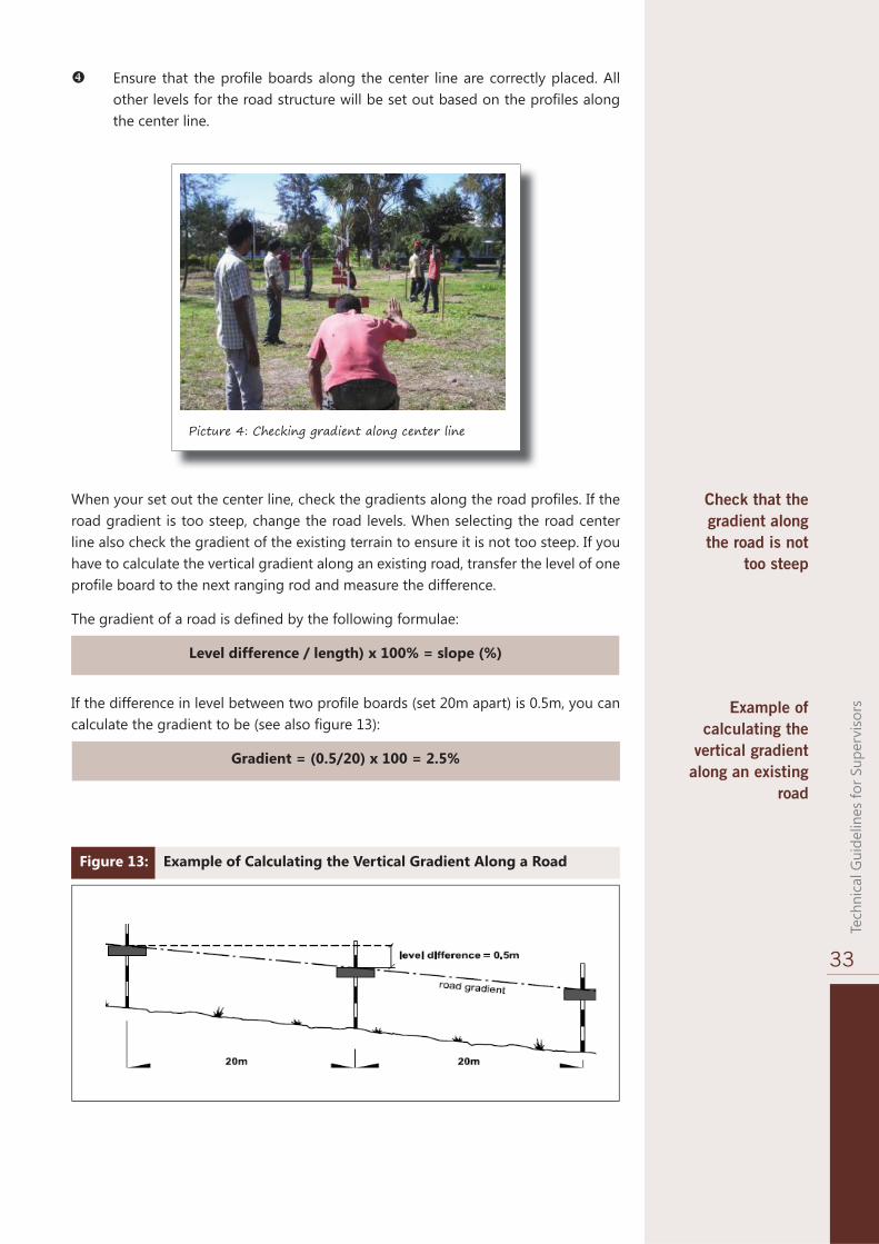
Ensure that the profi le boards along the center line are correctly placed. All other levels for the road structure will be set out based on the profi les along the center line.
Picture 4: Checking gradient along center line
Check that the gradient along the road is not
too steep
When your set out the center line, check the gradients along the road profi les. If the road gradient is too steep, change the road levels. When selecting the road center line also check the gradient of the existing terrain to ensure it is not too steep. If you have to calculate the vertical gradient along an existing road, transfer the level of one profi le board to the next ranging rod and measure the difference.
The gradient of a road is defi ned by the following formulae:
Level difference / length) x 100% = slope (%)
If the difference in level between two profi le boards (set 20m apart) is 0.5m, you can calculate the gradient to be (see also fi gure 13):
Gradient = (0.5/20) x 100 = 2.5%
Example of calculating the
vertical gradient along an existing
road
Figure 13: Example of Calculating the Vertical Gradient Along a Road

34
Job
Opp
ortu
nite
s fo
r You
th -
JOY
An example of setting out a vertical gradient with profi le boards is shown in fi gure 14. If you have to set out a vertical gradient of 5% over a horizontal length of 15 meters, you can calculate the required height difference:
Height difference = 5% x 15m = (5/100) x 15m = 0.75m
Next, transfer the level of one profi le to the ranging rod 15m away and set the profi le board 0.75 m above this mark. The two boards are then set at a slope of 5%.
Example of setting out a vertical gradient
Figure 14: Setting Out a Vertical Gradient
In those cases where levels have to be set out below the line of sight, a temporary traveler needs to be used, as is shown in fi gure 15.
Figure 15: Setting Out Levels Below the Line of SightExample of setting out a level below the line of sight
If you have to set out a vertical curve over a hill or through a sag the profi le boards are set out to give a standard depth of dig to the drain and then adjusted by eye to give a smooth curve. The spacing of 20m between the profi le boards is enough to make a series of straight lines appear as a curve when the road is fi nished (see also fi gure 16).

35
Tech
nica
l Gui
delin
es fo
r Sup
ervi
sors
Figure 16: Setting Out Vertical Curves Example of setting out a vertical
curve over a hill
For setting out a vertical curve though a valley or a dip, in principle the same principle is applied as when setting out a vertical curve over a hill. But now you can use a nylon string line to set out a smooth “sag vertical curve”.
To minimize quantities of earthwork it may be possible to vary the vertical gradient. If the height of the profi le boards above the ground level is more than 10cm +/- the 1m level, inspect the gradient and adjust it as shown in fi gures 17 and 18. When doing this, keep in mind that the vertical gradient should not exceed the maximum allowable vertical gradient of 12%.
Example of setting out a vertical curve through a valley or
a dip
Example of minimizing
earthwork by varying the
vertical gradient
Figure 17: Excessive Cut When Applying a Straight Gradient
Figure 18: Minimizing Cut by Applying Two Different Gradients

36
Job
Opp
ortu
nite
s fo
r You
th -
JOY
7.1.4 Mitre Drains
A mitre drain is a drain that empties the side drain at regular intervals before the volume of water builds up in the side drain and causes erosion.
After your have determined the gradient of the mitre drain, set out this gradient with profi le boards (fi gure 19). Then use a Temporary Traveler to see how far your have to go to get the three profi les to line up. The position where the Temporary Traveler rests on the ground and lines up with the two fi xed profi le boards shows where no excavation is needed and is therefore the end of the drain.
Example of setting out the length of a mitre drain
7.1.5 Side Drains
Figure 20 shows how to set out a side drain with a straight gradient by using profi le board, even though the depth of the excavation will vary along its length.
Figure 19: Setting Out the Length of a Mitre Drain
Figure 20: Setting Out Side Drains
7.1.6 Cross Sections
Once the position and levels of the center line have been determined, it is possible to set-out the side drains and the camber. Cross sections should be set out at right angles to the center line of the road by using the 3-4-5 method. An example of a cross-section is presented in fi gure 21. Dimensions may vary, based on the actual design specifi cations. The road camber is set out together with the side drains.
Example of setting out a side drain with a straight gradient

37
Tech
nica
l Gui
delin
es fo
r Sup
ervi
sors
Procedure for setting out cross sections that minimize earthwork:
On the center line, set out ranging rods at 10m intervals over a section of 50 to 100 meters. At the start of the section, set out the position of the road shoulders and the outer end of the side drains. Repeat this at the other end of the section. Place a wooden peg next to each of the ranging rods.
Sight in intermediate rods at every 10m along the road shoulders and side drains (fi gure 22). Place pegs next to each of the intermediate ranging rods.
Figure 21: Example of a Cross-Section of a Gravel Road
10 steps for setting out cross sections
Figure 22: Setting out ranging rods and pegs to mark center line, shoulders and side drains
On the center line, fi x profi le boards at the start and end of the section (fi gure 23).
Figure 23: Set up profi le boards at the start and end of the section

38
Job
Opp
ortu
nite
s fo
r You
th -
JOY
Sight in the intermediate profi les from one end and fi x profi le boards on the intermediate ranging rods along the center line so that they are all at the same level (fi gure 24).
Figure 24: Sighting of profi les on intermediate ranging rods
Check the height of each profi le board. If the height of the profi le boards differs more than 10cm from 1m, inspect the line. It may be that the set out line is over a hill or a dip in the terrain. Then, you have to adjust the profi les to avoid too much excavation.
Transfer the levels to the ranging rods at the outer end of the side drains (fi gure 25). Start at the beginning of the road section. Use a string and line level to transfer the level of the profi le board at the center line to the side drains. Set out the levels with profi le boards and mark them on pegs next to each ranging rod. Repeat this procedure for the same two ranging rods at the other end of the road section and also for the intermediate profi les. Then, sight in the intermediate side drain levels.
Figure 25: Transfer levels of center line to the outer side of the drains
Usually the height of the drain profi le on the low side of the center line is more than 1m. This is because you have started from higher grounds, and since the road is level, the lower side drains will be less deep.
Mark the levels for the center line on pegs placed next to the ranging rods along the center line. Then use the center line profi le boards to set out intermediate pegs every 5m along the center line. This is can be done with a 1m temporary traveler. Mark these pegs at the point where the bottom of the traveler touches the peg, when lined up with the profi les. On all the center line pegs, mark the level of the crest of the camber 0.25m above the 1meter

39
Tech
nica
l Gui
delin
es fo
r Sup
ervi
sors
level on the pegs. You have now set out profi les for the leveling of this road section.
For setting out the levels of the shoulders use a traveler of 1m high. When you line up the traveler along the line between the two side drain profi les, the bottom of the traveler will show the correct shoulder level (fi gure 26).
Figure 26: Set out the level of the shoulders
Place pegs every 5m along the edge of the shoulder and, using the traveler, mark these pegs at the point where the bottom of the traveler ends when it lines up with the profi les.
Locate and set out the mitre drains. This should be done before the excavation works for the side drains and camber start.
Set out with a string line the side drains that needs to be excavated. Remember to leave out the mitre drain block-offs.
Normally, sections of not more than 50 to 100m are set out at the time in fl at terrain. In mountainous terrain, sections of less than 20m may be chosen. A typical cross-section in mountainous terrain with a cross-fall of 5% is shown in fi gure 27.
Figure 27: Example of Cross-Section in Mountainous Terrain
Example of typical cross
section in mountainous
terrain

40
Job
Opp
ortu
nite
s fo
r You
th -
JOY
7.2 Clearing
Clearing involves cutting down and removing trees, clearing of bush and digging up and removing root systems. Avoid heavy bush clearing and unnecessary cutting down of trees wherever possible by careful selection of the center line. When you cannot avoid cutting trees, dig up and remove the roots as well to a depth of more than 200mm below ground level. Fill holes caused by extracting roots and compact these fi lled holes properly using hand rammers. Heavy grass cover should be cleared. Light grass cover can usually be used in construction earthworks without too much of a problem. Afterwards it re-grows, forming protection against erosion on the shoulders. Heavy grass tufts can be used to protect side slopes in.
Try to avoid the need for removing big boulders as this work is often time consuming and expensive. Where there are many big boulders in the soil, which creates problems in excavating the drains, consider the possibility of raising the road level.
Topsoil usually only needs to be removed when it is deep (more than 10-15cm), very organic and has much less strength than the soil below. Topsoil removal is most likely to be needed in river valleys and fl ood areas that build up silt. Most agricultural land and open areas are eroded, with a very thin topsoil layer remaining, which can be mixed in with the earthworks for the road construction.
7.3 Earth Works
Earthworks includes digging drains and building up the road formation and the camber (or cross-fall). When setting out alignments, always try to do this in such a way that it minimizes earthwork. This is the case for both new road construction and the rehabilitation or upgrading of existing roads.
Figure 28 gives and example of excavation works in fl at terrain (i.e. with very little cross slope). Because there are usually low spots in the ground, use slightly more materials from the side drain to form the camber than what is actually required.
Clearing of bush, trees and grasses
Removing boulders
Removal of top soil
Always try to minimize earthworks
Earthwork in fl at terrain
Figure 28: Example of Earthwork in Flat Terrain
To form the road excavate material from the drains and place it on top of the road-bed to form the sub-grade layer. The excavated material should be of sub-grade quality. Remove stones, boulders and organic soil. Make sure that the camber and drains are formed as per design specifi cations. Annex 5 provides an overview of the different types of soils that can be distinguished, their key characteristics and an explanation of the terminology used in describing soils.
Excavation of drains and formation of camber

41
Tech
nica
l Gui
delin
es fo
r Sup
ervi
sors
In sloping terrain (fi gure 29) try to reduce earthwork. Locate the road on ridges where possible - this will reduce earthwork and drainage works. The high side drain normally has to be dug deep whereas normally no low side drain is needed. On the low side of the cross slope the road usually has to be build on a fi ll.
Figure 29: Example of Earthwork in Sloping Terrain
In sloping terrain minimize earthwork
and balance cut and fi ll
In sloping terrain build the road in two stages. Using this method you can keep the earthwork to a minimum as cut and fi ll are balanced and it will usually avoid the need for a side drain on the low side.
Stage 1: Excavate the high side and build up the low side and form the side slope on the low side (fi gure 30).
Figure 30: Stage 1 in constructing a road in sloping terrain 2 stages in constructing a road in sloping
terrain
Stage 2: Excavate the high side drain and form the camber.
Figure 31: Stage 2 in constructing a road in sloping terrain
Figure 32 shows how to balance the earthwork cut and fi ll using this method. When you balance cut and fi ll, make sure to leave suffi cient space for the side drain on the high side. In the example of fi gure 32 the ground needs to be leveled to 4.25m back from the center line to provide enough room to dig and back slope the side drain. The width of the back slope to the excavation should be suffi cient to achieve a slope of 1:1, similar to the back slope of the side drain.

42
Job
Opp
ortu
nite
s fo
r You
th -
JOY
Picture 5: Cutting and leveling
Minimize earthwork by balancing cut and fi ll in construction of road
Figure 32: Example of Balancing Cut and Fill in Earthworks
If there is too much excavation work for a gang to fi nish in one day, the work needs to be divided over several days. In the example of fi gure 33 the height at the beginning of a 20m long section is 43cm at the end the height is 59cm, so the average height H = (43 + 59)/2 = 51cm.
Calculating the quantities of earthwork to be excavated
Figure 33: Example for Calculating Earthwork Excavation Works

43
Tech
nica
l Gui
delin
es fo
r Sup
ervi
sors
The length along the cross-section to be excavated is 4.25 meters (see fi gure 33). This excludes the excavation of the back slope. For back slopes with a gradient of 1:1 fi gure 35 shows how this area of excavation can be calculated. In this example H = 0.51 meter, so X = 1 – H = 0.49 meter. D = 4.25 meter and L = 20 meter.
Using the formulae in fi gure 34, the volume V of earthwork to excavate is:
V = ((D2 x X) / (2 x (D-X)) x L, so
V = ((4.252 x 0.49) / (2 x (4.25-(4.25-0.49)) x 20 = 23.5 m3
If for example one labourer can excavate 1.45 m3 earth per day, the number of labour-days to excavate 23.5m3 = 23.5 / 1.45 ≈ 16 labour-days.
Suppose a gang consists of 8 labourers, this means 16 labour-days / 8 labourers = 2 days are required to complete the work. On each of the 2 days the volume of earthwork to be excavated is 23.5 / 2 = 11.75 m3. Figure 35 shows how this can be set out for this example.
Example of calculating
the quantity of earthwork to be
excavated
Formulae used to calculate quantity
of earthwork in excavation
Figure 34: Formulae to Calculate Area of Excavation

44
Job
Opp
ortu
nite
s fo
r You
th -
JOY
Figure 35: Example of Calculating the Daily Area to be Excavated
0.49 m
4.25 m
Y
Z
A 1 Area to Excavate on day 1
A 2 Area to excavate on day 2
The area to be excavated during day 1 = 11.75m3 = 20 x A1.
A1 = (Y x Z) / 2 so : 11.75 m3 = 20 x ((Y x Z) / 2). We need to know how much Z is.
This we can do as follows:
Y / Z = 0.49 / 4.25 or 4.25 x Y = 0.49 x Z or Y = (0.49 x Z) / 4.25 or Y = 0.1153 x Z
Then fi ll in Y = 0.1153 x Z in 11.75 m3 = 20 x ((Y x Z) / 2). This gives:
11.75 = 20 x (0.1153 x Z x Z) / 2 or 20 x (0.1153 x Z2) / 2 = 1.153 x Z2. or 11.75 m3 = 1.153 x Z2. or Z2 = 11.75 / 1.153 = 10.19. So Z = (10.19)1/2 = 3.19 meter.
A horizontal distance of 3.19 meter thus needs to be excavated during day 1. The remaining volume of the cross-section (area A2) needs to be excavated during day 2.
To ensure that the cut is fully excavated for a day of work, a temporary traveler can be used as shown in fi gure 36.
Figure 36: Using Traveler to Check that Earthwork Excavation is done as Required
Use a traveler to check that earthwork excavation is done as per requirements
If the area to excavated is very high, the top section is usually excavated fi rst. Figure 37 shows an example of how the work could be organized on such a section. In this example 3 days will be required for the excavation works.

45
Tech
nica
l Gui
delin
es fo
r Sup
ervi
sors
Figure 37: Example of setting out excavation works over a period of 3 days
The excavated soil is used to form the fi ll side. If the haulage distance from the excavation site to the fi ll site is small, you will usually need twice as many labourers for the excavation (cut) works than for the fi ll works.
If the depth of the fi ll on the low side road shoulder is greater than 0.3m, there is usually no need for a side drain on the low side of the road. Make sure that the slope of the fi ll has a slope of 1:2 as shown in the fi gure below.
For excavation works usually twice as many labourers are needed as for
fi ll works
The slope of the fi ll needs to be generally 1:2,
depending on the soil typeFigure 38: Setting out a slope of the fi ll of 1: 2
To get a good quality fi ll on the low side, make sure that the soils are properly compacted. The fi ll needs to be built up in layers of 15cm, and each of these layers needs to be well compacted before a new layer is added (see fi gure 39). If the area is too small to use mechanical compaction equipment, use hand rammers for compaction.
Figure 39: building up fi ll through compacted layers
Fill should be built up in layers and
the layers need to be well

46
Job
Opp
ortu
nite
s fo
r You
th -
JOY
Benching of the fi ll side is also recommended as this will minimize the risk of slippage of the fi ll material over the existing ground. Figure 40 shows how to do this.
Figure 40: Keying of the fi ll material through benching
Once the excavation and fi ll have been completed, construct the road camber using soil from the side drains and back slope. Usually less labourers are needed for excavating the back slope than for excavating the drains. The excavated soils is thrown to the center of the road and from there it is leveled out towards each road shoulder to form the camber (see fi gure 41 and picture 6). Picture 7 shows a completed camber for a gravel road.
Constructing camber from soils from side drains and back slope
Figure 41: Constructing camber using soils from side drains and back slope
Picture 6 : Constructing camber with soils from side drains

47
Tech
nica
l Gui
delin
es fo
r Sup
ervi
sors
Picture 7: Completed camber of gravel road
Side drain excavation is done by fi rst excavating the ditch and then forming the side slopes of the ditch (fi gure 42). The side drain excavation is set out using string line and pegs, and controlled by using ditch templates.
Side drains are excavated in two
stages
Figure 42: Two-staged side drain excavation
To achieve an exact and properly leveled camber, the work is set out using pegs and strings (see fi gure 43). Once the soils for the camber has been leveled, the camber is properly compacted. Make sure that the soils contain optimal moisture content
Figure 43: Setting out camber by using pegs and strings
To check whether the achieved levels of the road camber are exact and to the prescribed standard and quality This can be done by setting out the profi le boards and checking the level between the profi les with a traveler. A quicker but less accurate

48
Job
Opp
ortu
nite
s fo
r You
th -
JOY
method is to use string lines (fi gure 44 and picture 9). If the levels are inaccurate, it should be corrected. If more fi lling is needed, make sure that these patches are properly compacted.
Picture 8: Compacting while maintaining camber
Figure 44: Checking the camber using pegs and stringsCheck the camber using pegs and strings or with profi le boards
Picture 9: Checking the camber using pegs and strings

49
Tech
nica
l Gui
delin
es fo
r Sup
ervi
sors
Figure 45: Example of inverting the camber in a sharp curve
If there are sharp curves in the road where vehicles can maintain a high speed, invert the camber of the road (see also fi gure 43). This will reduce the risks of slipping vehicles. Inverting the camber is gradually built up over a 20m section before entering into the curve.
In sharp curved the camber of on the
outer side needs to be inverted
7.4 Graveling
In the past graveling of roads was considered an effective and cost-effective option for surfacing low-volume rural roads. Recent research however shows that gravel roads have serious limitations in many situations. Very often gravel surfaces are not appropriate, affordable or sustainable for rural roads. There are for example serious problems related to the maintenance and sustainability of gravel surfaces (or ordinary earth roads). Although the initial construction costs of gravel roads are low, the maintenance costs are very high.
The suitability of graveling roads depends on a range of factors. These include for example the road gradient, rainfall, material quality, haul distance and maintenance regime. Gravel should NOT be used if any of the following conditions, or a combination of them applies:
Gravel quality is poor;
Compaction & thickness cannot be assured ;
Haul distances are longer than 10km;
Rainfall is very high – Gravel loss is related to rainfall;
There are dry season dust problems;
Traffi c levels are high, i.e. more than 200 vehicle equivalents per day;
Road gradients are more than 6% (with < 1,000mm rain per year) or more than 4% (with 1,000 – 2,000mm rain per year);
If rainfall is more than 2,000mm/year;
Adequate maintenance cannot be provided;
Sub-grade is weak or soaked;
Gravel deposits are limited or environmentally sensitive.
Gravel surfaces have many limitations
Situations where gravel is not suitable as surface option


![Yogi Bhajan - Yoga for Youth & Joy [OCR]](https://static.fdocuments.net/doc/165x107/55cf9cc7550346d033ab0546/yogi-bhajan-yoga-for-youth-joy-ocr.jpg)