JINMA 200 Series DOCUMENTATION - Atlantic Imports · JINMA 200 Series DOCUMENTATION Edited by: ......
52
Jinma 200 series Tractor Users Manual MCE 2004.01 JINMA 200 Series DOCUMENTATION Edited by: Steve Bradshaw Malacat Enterprises Cobble Hill, B.C. Version 0.2 Page 1 of 52
Transcript of JINMA 200 Series DOCUMENTATION - Atlantic Imports · JINMA 200 Series DOCUMENTATION Edited by: ......

Jinma 200 series Tractor Users Manual
MCE 2004.01
JINMA 200 SeriesDOCUMENTATION
Edited by: Steve BradshawMalacat Enterprises
Cobble Hill, B.C.
Version 0.2 Page 1 of 52
jim betts
Cross-Out
jim betts
Inserted Text
Jim Betts President & CEO JDB Sales and Services 6892 Upper Big Chute Road Box A469, RR1 Coldwater Ontario, Canada, L0K 1E0 Tel: 416-915-4076 Toll Free: 1-877-809-0009 Fax: 416-761-5091 jim@ <mailto:[email protected]>jinma.ca www.jinma.ca <http://www.jinma.ca/>
jim betts
Inserted Text

Jinma 200 series Tractor Users Manual
MCE 2004.01
Table of Contents
INTRODUCTION......................................................................................................................................7Sources of data .................................................................................................................................7PARTS..............................................................................................................................................7
Yancheng Tractor Factory..........................................................................................................................8THE RULES..............................................................................................................................................9Preventing Farm Machine Hazards..........................................................................................................11
AEX59391...................................................................................................................................11Shear and Cutting Points................................................................................................................11Pinch Points ...................................................................................................................................12Wrap Points ...................................................................................................................................12Crush Points ...................................................................................................................................12FreeWheeling Parts.......................................................................................................................13Springs............................................................................................................................................13Burn Points.....................................................................................................................................13Hydraulic Systems..........................................................................................................................13
MATERIAL SAFETY DATA SHEETS.................................................................................................15DISPOSAL OF POL WASTE........................................................................................................16ENVIROMENTIAL LAW.............................................................................................................16
Controls and Instruments.........................................................................................................................17Instruments (Standard)....................................................................................................................17Amp meter:.....................................................................................................................................17Water Temperature Gauge:.............................................................................................................17Oil Pressure Gauge.........................................................................................................................17Tachometer.....................................................................................................................................17Turning Signal Switch....................................................................................................................17Work Light Switch.........................................................................................................................17Horn Button....................................................................................................................................17Headlight Switch............................................................................................................................17Starting Switch...............................................................................................................................18
Instruments (Optional).............................................................................................................................18Amp meter......................................................................................................................................18Water Temperature Gauge..............................................................................................................18Tachometer/Hour Meter:................................................................................................................18Oil Pressure Gauge.........................................................................................................................18Fuel Gauge......................................................................................................................................18
OPERATING CONTROLS.....................................................................................................................19Engine Shutoff Handle...................................................................................................................19Compression Release......................................................................................................................19Hand Throttle..................................................................................................................................19Clutch Pedal....................................................................................................................................194WD Selector..................................................................................................................................19
Version 0.2 Page 2 of 52
Jinma 200 series Tractor Users Manual
MCE 2004.01
Transmission Gear Selector............................................................................................................19HiLo Range Gear Shifting Lever..................................................................................................20Left and Right Brake Pedals...........................................................................................................20Foot Throttle Pedal.........................................................................................................................20Parking Brake Lock Pawl...............................................................................................................20Creeper Shifting Lever...................................................................................................................20Hydraulic Control Lever.................................................................................................................20Differential Lock Lever..................................................................................................................20Hydraulic Speed Regulator.............................................................................................................20
Control and Operation of the Tractor.......................................................................................................21Starting Engine...............................................................................................................................21
Warm weather over 32 Degrees F..............................................................................................21Cold weather below 32 Degrees F ............................................................................................21
Operating the Tractor......................................................................................................................21Driving the Tractor.........................................................................................................................22Proper speed should be selected for best productivity. ..................................................................22Stopping the Tractor.......................................................................................................................22Tractor Operation Safety................................................................................................................22
Control and Operation of the Working Devices.......................................................................................23Control and Operation of PTO............................................................................................................23Control and Operation of Hydraulic Hitch System.............................................................................24
Position Control..............................................................................................................................24Floating Control..............................................................................................................................24Control of the Lowering Speed of the Implement..........................................................................24
Operation of Hitch System..................................................................................................................24Adjusting of Longitudinal Level....................................................................................................24Adjusting of Lateral Level..............................................................................................................25
Use of the Electrical Equipment..............................................................................................................26Battery.............................................................................................................................................26The Starter......................................................................................................................................26
Maintenance Schedule for the Tractor.....................................................................................................27Daily Maintenance..........................................................................................................................2750 Hour Maintenance (Every 50 Hours).........................................................................................27250 Hour Maintenance (Every 250 Hours).....................................................................................27500 Hour Maintenance (Every 500 Hours).....................................................................................271000 Hour Maintenance (Every 1000 Hours).................................................................................28Maintenance for Long Term Storage..............................................................................................28
Tractor Adjustments.................................................................................................................................29Adjustment of clutch.......................................................................................................................29Adjustment of brake.......................................................................................................................30Adjustment of disc brake................................................................................................................31
Free state adjustment of disc brake ...........................................................................................31Travel adjustment of brake pedal...............................................................................................31
Troubleshooting guide for Diesel Engines...............................................................................................32SERVICE ADVISORIES........................................................................................................................34
Version 0.2 Page 3 of 52
Jinma 200 series Tractor Users Manual
MCE 2004.01
50 hour, Head Retorque.................................................................................................................341828 HP Jinma Tractor Hydraulic Fluid Intake Filter .................................................................36Backhoe Hydraulic Fluid Intake Filter ..........................................................................................38Injector Pump Oil ..........................................................................................................................40Oil Drains .......................................................................................................................................41Ignition Switch Retrofit .................................................................................................................42
Jinma 254 Specifications..........................................................................................................................43Jinma Crate Tractor Assembly ................................................................................................................46Jinma JW03 Backhoe Info .....................................................................................................................50
PIVET PINS...................................................................................................................................50Enlarge outrigger pads. ...............................................................................................................51Strengthen lower subframe. .........................................................................................................51Stiffen up rear mount ....................................................................................................................52
Version 0.2 Page 4 of 52
Jinma 200 series Tractor Users Manual
MCE 2004.01
Index of Illustrations, drawings and photos.
Figure 1. A 254 at the factory......................................................................................................8Figure 2. Yancheng City..............................................................................................................8Figure 3. Old Factory with dirt floors..........................................................................................8Figure 4. New factory machine shop...........................................................................................8Figure 5. Engine assembly in the new plant................................................................................8Figure 6. Map of Jiansu Province ...............................................................................................8Figure 7. Shear Point....................................................................................................................11Figure 8. Pinch Points..................................................................................................................12Figure 9. Crush Points..................................................................................................................13Figure 10. Spring dangers.............................................................................................................13Figure 11. Old style instrument panel...........................................................................................17Figure 12. Old style lower dash switches .....................................................................................17Figure 13. New style electronic instrument cluster.......................................................................18Figure 14. New style lower dash switches....................................................................................18Figure 15. Driving Controls..........................................................................................................19Figure 16. Ignition Switch ...........................................................................................................21Figure 17. Clutch cut away diagram.............................................................................................29Figure 18. Brake cut away diagram..............................................................................................30Figure 19. TY290 Engine............................................................................................................34Figure 20. JM204 TY29 Engine with valve cover removed........................................................34Figure 21. Closeup of JM204 TY290 engine head.....................................................................34Figure 22. Y385 Torque Sequence, used for JM254/284.............................................................35Figure 23. TY20 Torque Sequence, used in JM184/204/224.......................................................35Figure 24. Hydraulic Filter Assembly...........................................................................................36Figure 25. Hydraulic filter disassembly........................................................................................37Figure 26. Hydraulic Filter Parts...................................................................................................37Figure 27. Hoe Hydraulic Oil Filter..............................................................................................38Figure 28. Hoe Hydraulic Filter oring.........................................................................................38Figure 29. Fuel Injector Oil filler (A) & Drain (C).......................................................................40Figure 30. Fuel Injector Breather (A) and Cap (B)......................................................................40Figure 31. Fuel Injector Assembly................................................................................................40Figure 32. Fuel Injector Steel Balls..............................................................................................40Figure 33. Transmission Oil Drain...............................................................................................41Figure 34. Engine Oil Drain..........................................................................................................41Figure 35. Hydraulic System Oil Drain........................................................................................41Figure 36. JW03 Backhoe showing modification points.............................................................50Figure 37. Flat bar details.............................................................................................................50Figure 38. JW03 Pivot pins.........................................................................................................50Figure 39. Enlarged Outrigger Pads..............................................................................................51Figure 40. Hoe Frame showing heavy reinforcement ..................................................................51Figure 41. Hoe frame damage.......................................................................................................51
Version 0.2 Page 5 of 52

Jinma 200 series Tractor Users Manual
MCE 2004.01
Figure 42. Hoe frame reinforcement fwd view.............................................................................51Figure 43. Hoe frame reinforcement after view............................................................................51Figure 44. Hoe frame top link stabilizer.......................................................................................52
Version 0.2 Page 6 of 52
Jinma 200 series Tractor Users Manual
MCE 2004.01
INTRODUCTION
This manual is a general guide to provide the user with general information withrespect to personnel and equipment safety, operational procedures andmaintenance of your machine. This manual was developed to fill the requirement for a JINMA specific operationsand maintenance manual. While Jinma tractors come with a set of 4 manuals,some of the language syntax is a little hard to follow.
Sources of data
Sources of data for this manual come from many places. They include , but arenot limited to the following:
http://www.johnstractor.homestead.com/, http://www.emerybuilt.com/ http://www.tractor-outlet.com/ http://www.china-tractors.com/ http://www.tractorpages.com/, http://chinabestproducts.comFactory Engine Operations Manual, Factory Tractor Operations and Maintenance Manual, Factory Tractor Illustrated Parts Breakdown Manual, Factory Engine Illustrated Parts Breakdown Manual.
The Chinese Tractor Owner Association is a good place to lurk, ask questions andget/give support from/to others. http://www.ctoa.net
Please read this manual carefully and keep in a convenient place for futurereference.
Do not hesitate to contact your local dealer for any questions concerningthe tractor. Even if you obtained this tractor as a crate assembly project, a
tractor dealer can provide skilled personnel, spare parts and all tools andequipment necessary for your service requirements. Most of all, a dealer willhave the experience of working with tractors and small diesel engines.
PARTS
Parts are readily available for JINMA series tractors. The Internet is a good placeto find sources of parts. http://www.jinmaparts.com is but one company sellingparts for your machine.
Any suggestions and or comments about this manuals contents, errors oromissions are most welcome. Please email or mail:
Steven Bradshaw1033 Braithwaite DriveCobble Hill, BCCanada. V0R[email protected]
Version 0.2 Page 7 of 52
Jinma 200 series Tractor Users Manual
MCE 2004.01
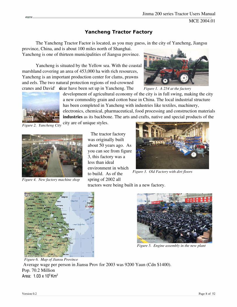
Yancheng Tractor Factory
The Yancheng Tractor Factor is located, as you may guess, in the city of Yancheng, Jiangsuprovince, China, and is about 100 miles north of Shanghai.Yancheng is one of thirteen municipalities of Jiangsu province.
Yancheng is situated by the Yellow sea. With the coastalmarshland covering an area of 453,000 ha with rich resources,Yancheng is an important production center for clams, prawnsand eels. The two natural protection regions of redcrownedcranes and David' s dear have been set up in Yancheng. The
development of agricultural economy of the city is in full swing, making the citya new commodity grain and cotton base in China. The local industrial structurehas been completed in Yancheng with industries like textiles, machinery,electronics, chemical, pharmaceutical, food processing and construction materialsindustries as its backbone. The arts and crafts, native and special products of thecity are of unique styles.
The tractor factorywas originally builtabout 50 years ago. Asyou can see from figure3, this factory was aless than idealenvironment in whichto build. As of thespring of 2002 alltractors were being built in a new factory.
Average wage per person in Jiansu Prov for 2003 was 9200 Yaun (Cdn $1400). Pop. 70.2 MillionArea: 1.03 x 10⁵ Km2
Version 0.2 Page 8 of 52
Figure 1. A 254 at the factory
Figure 2. Yancheng City
Figure 5. Engine assembly in the new plant
Figure 3. Old Factory with dirt floors
Figure 4. New factory machine shop
Figure 6. Map of Jiansu Province
Jinma 200 series Tractor Users Manual
MCE 2004.01
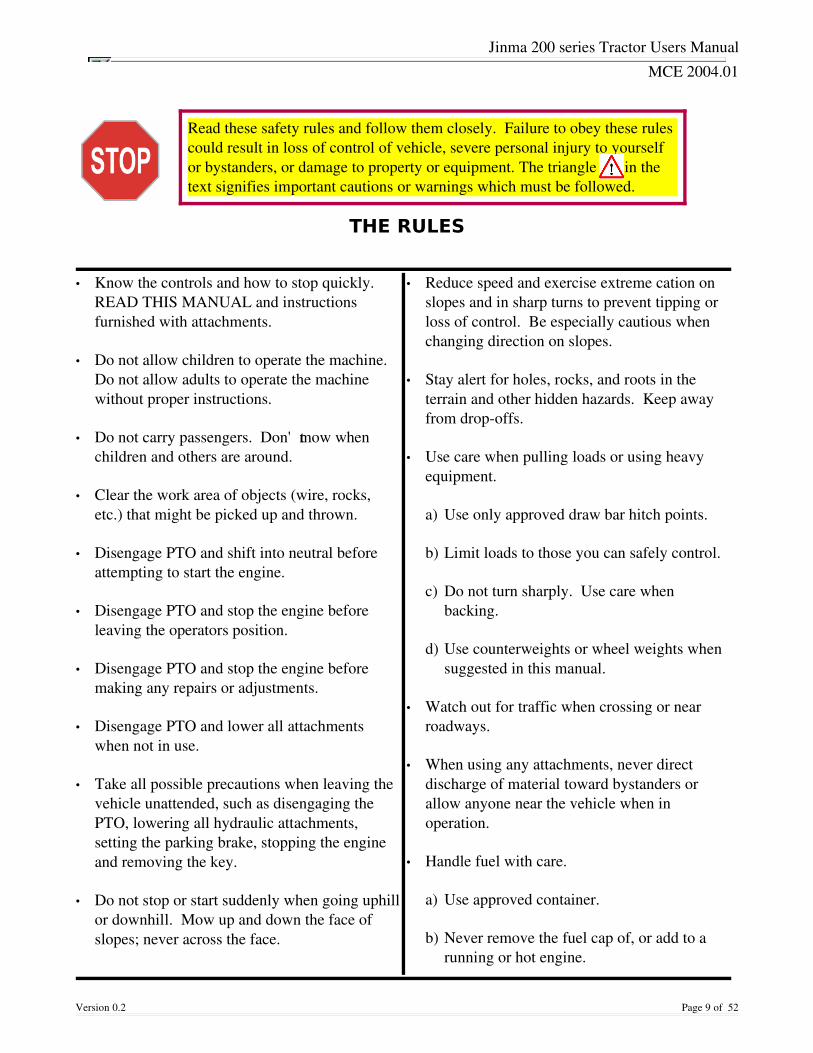
THE RULES
Version 0.2 Page 9 of 52
• Know the controls and how to stop quickly.READ THIS MANUAL and instructionsfurnished with attachments.
• Do not allow children to operate the machine.Do not allow adults to operate the machinewithout proper instructions.
• Do not carry passengers. Don't mow whenchildren and others are around.
• Clear the work area of objects (wire, rocks,etc.) that might be picked up and thrown.
• Disengage PTO and shift into neutral beforeattempting to start the engine.
• Disengage PTO and stop the engine beforeleaving the operators position.
• Disengage PTO and stop the engine beforemaking any repairs or adjustments.
• Disengage PTO and lower all attachmentswhen not in use.
• Take all possible precautions when leaving thevehicle unattended, such as disengaging thePTO, lowering all hydraulic attachments,setting the parking brake, stopping the engineand removing the key.
• Do not stop or start suddenly when going uphillor downhill. Mow up and down the face ofslopes; never across the face.
• Reduce speed and exercise extreme cation onslopes and in sharp turns to prevent tipping orloss of control. Be especially cautious whenchanging direction on slopes.
• Stay alert for holes, rocks, and roots in theterrain and other hidden hazards. Keep awayfrom dropoffs.
• Use care when pulling loads or using heavyequipment.
a) Use only approved draw bar hitch points.
b) Limit loads to those you can safely control.
c) Do not turn sharply. Use care whenbacking.
d) Use counterweights or wheel weights whensuggested in this manual.
• Watch out for traffic when crossing or nearroadways.
• When using any attachments, never directdischarge of material toward bystanders orallow anyone near the vehicle when inoperation.
• Handle fuel with care.
a) Use approved container.
b) Never remove the fuel cap of, or add to arunning or hot engine.
Read these safety rules and follow them closely. Failure to obey these rulescould result in loss of control of vehicle, severe personal injury to yourselfor bystanders, or damage to property or equipment. The triangle in thetext signifies important cautions or warnings which must be followed.
Jinma 200 series Tractor Users Manual
MCE 2004.01
Version 0.2 Page 10 of 52
• Open doors if the engine is run a confinedspace – exhaust fumes are dangerous. Do notrun the engine indoors.
• Keep the vehicle and attachments in goodoperating condition, and keep safety devices inplace and in working condition.
• Keep all nuts, bolts and screws tight to be surethe equipment is safe to operate.
• To reduce the risk of fire, keep the engine andexhaust system free of grass, leaves orexcessive grease.
• The vehicle and attachments should be stoppedand inspected for damage after striking aforeign object, and damage should be repairedbefore restarting and operating the equipment.
• Do not change the speed governor setting orover speed the engine.
• When welding, make sure that hoses areproperly protected as sparks or molten materialmay puncture or weaken the tubes and sleeves,resulting in leakage or of oil, cooling liquid,etc.
• Avoid using unsuitable, pressurized fillingsystems or fuel cans when filing tanks, as thesemay cause considerable spillage and leakage ofliquids.
• As a general rule, do not allow liquid fuels,lubricants, acids, solvents, etc. to come intocontact with the skin. The majority of theseproducts contain substances that are potentialhealth hazards.
• Modern lubricants contain additives. Do notburn contaminated fuel oils and/or oils used inconventional heating systems.
• Avoid spillage when transferring used enginecooling liquids, engine and transmissionlubricants, hydraulic oils, etc. Never mix usedfuel oil with lubricants. Store safely untilsuitable disposal can be arranged according tonational legislation or local regulations.
• Modern antifreeze liquids and solutions, e.g.:antifreeze and other additives must be replacedevery two years. They must not be left to beabsorbed into the ground, but must be collectedand disposed of in a suitable manner.
• Any leakage or defect in the engine cooling orhydraulic systems must be repairedimmediately.
• Do not increase the pressure in pressurizedsystems, as this may cause component parts toburst.
• When welding, make sure that hoses areproperly protected as sparks or molten materialmay puncture or weaken the tubes and sleeves,resulting in leakage or of oil, cooling liquid,etc.

Jinma 200 series Tractor Users Manual
MCE 2004.01
Preventing Farm Machine Hazards
AEX-593-91
Thomas L. Bean
Each year, 2,600 farm residents are killed and 230,000 disabled in farmrelated injuries, many due tofarm machinery. Farm machinery uses mechanical power to do work. This creates a number of possiblehazards for both operators and bystanders. Even though manufacturers take many steps to makemachinery safe, all hazards cannot be removed. Some machine parts cannot be completely shielded andstill do their job. For instance, a totally enclosed cutting blade could not cut.
Many machineryrelated accidents result from human error. The operator either forgot something, tooka shortcut or a risk, ignored a warning, wasn't paying close attention, or failed to follow safety rules. Inaddition, guards removed for maintenance often aren't replaced.
There are many different kinds of farm machinery: mowers, tractors, shredders, harvesters, grinders,blowers, augers, balers, etc. They all have similar characteristics and hazards. You can be cut, crushed,pulled in or struck by an object thrown by these machines. They have cutting edges, gears, chains,revolving shafts, rotating blades, pinch points and other hazards. You can also be injured if you fallwhile working on or near any of these machines.
Accidents with farm machinery are often serious, even fatal. It is important to recognize and be alert formachine hazards and to take precautions to avoid injury.
Shear and Cutting Points
Shear points (Fig. 1) are created when the edges of two objects are movedtogether closely enough to cut a soft material, as with a pair of shears or anauger. Cutting points are created when a single object moves forcefully orrapidly enough to cut, as with a rotary mower blade.
Both shear and cutting points are created on machinery designed to cut, such asharvesters, and on those that are not designed to cut, such as augers. They are hazardous because oftheir cutting force and they often move so rapidly that they may not be visible, so it is easy to forgetthey are operating or to underestimate the hazard.
Because some shear and cutting points cannot be guarded, it is important to be aware of their hazardand stay alert when they are operating. It is also important to warn others and to look out for theirsafety. This is especially true if there is a danger of thrown objects while using cuttingtype equipment.
Version 0.2 Page 11 of 52
Figure 7. Shear Point
Jinma 200 series Tractor Users Manual
MCE 2004.01
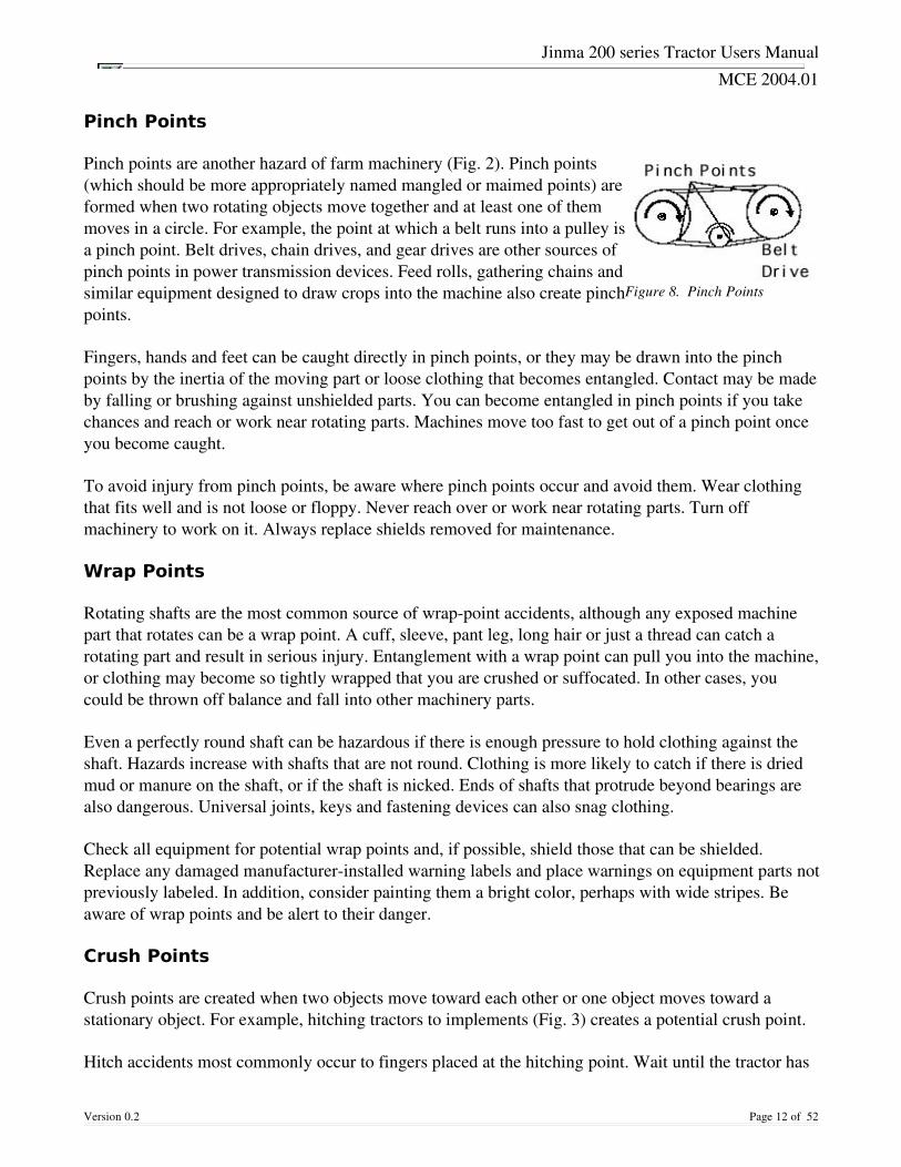
Pinch Points
Pinch points are another hazard of farm machinery (Fig. 2). Pinch points(which should be more appropriately named mangled or maimed points) areformed when two rotating objects move together and at least one of themmoves in a circle. For example, the point at which a belt runs into a pulley isa pinch point. Belt drives, chain drives, and gear drives are other sources ofpinch points in power transmission devices. Feed rolls, gathering chains andsimilar equipment designed to draw crops into the machine also create pinchpoints.
Fingers, hands and feet can be caught directly in pinch points, or they may be drawn into the pinchpoints by the inertia of the moving part or loose clothing that becomes entangled. Contact may be madeby falling or brushing against unshielded parts. You can become entangled in pinch points if you takechances and reach or work near rotating parts. Machines move too fast to get out of a pinch point onceyou become caught.
To avoid injury from pinch points, be aware where pinch points occur and avoid them. Wear clothingthat fits well and is not loose or floppy. Never reach over or work near rotating parts. Turn offmachinery to work on it. Always replace shields removed for maintenance.
Wrap Points
Rotating shafts are the most common source of wrappoint accidents, although any exposed machinepart that rotates can be a wrap point. A cuff, sleeve, pant leg, long hair or just a thread can catch arotating part and result in serious injury. Entanglement with a wrap point can pull you into the machine,or clothing may become so tightly wrapped that you are crushed or suffocated. In other cases, youcould be thrown off balance and fall into other machinery parts.
Even a perfectly round shaft can be hazardous if there is enough pressure to hold clothing against theshaft. Hazards increase with shafts that are not round. Clothing is more likely to catch if there is driedmud or manure on the shaft, or if the shaft is nicked. Ends of shafts that protrude beyond bearings arealso dangerous. Universal joints, keys and fastening devices can also snag clothing.
Check all equipment for potential wrap points and, if possible, shield those that can be shielded.Replace any damaged manufacturerinstalled warning labels and place warnings on equipment parts notpreviously labeled. In addition, consider painting them a bright color, perhaps with wide stripes. Beaware of wrap points and be alert to their danger.
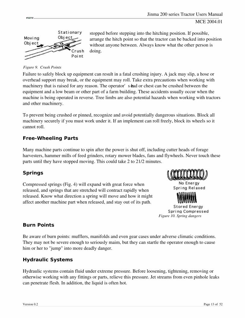
Crush Points
Crush points are created when two objects move toward each other or one object moves toward astationary object. For example, hitching tractors to implements (Fig. 3) creates a potential crush point.
Hitch accidents most commonly occur to fingers placed at the hitching point. Wait until the tractor has
Version 0.2 Page 12 of 52
Figure 8. Pinch Points
Jinma 200 series Tractor Users Manual
MCE 2004.01
stopped before stepping into the hitching position. If possible,arrange the hitch point so that the tractor can be backed into positionwithout anyone between. Always know what the other person isdoing.
Failure to safely block up equipment can result in a fatal crushing injury. A jack may slip, a hose oroverhead support may break, or the equipment may roll. Take extra precautions when working withmachinery that is raised for any reason. The operator's head or chest can be crushed between theequipment and a low beam or other part of a farm building. These accidents usually occur when themachine is being operated in reverse. Tree limbs are also potential hazards when working with tractorsand other machinery.
To prevent being crushed or pinned, recognize and avoid potentially dangerous situations. Block allmachinery securely if you must work under it. If an implement can roll freely, block its wheels so itcannot roll.
Free-Wheeling Parts
Many machine parts continue to spin after the power is shut off, including cutter heads of forageharvesters, hammer mills of feed grinders, rotary mower blades, fans and flywheels. Never touch theseparts until they have stopped moving. This could take 2 to 21/2 minutes.
Springs
Compressed springs (Fig. 4) will expand with great force whenreleased, and springs that are stretched will contract rapidly whenreleased. Know what direction a spring will move and how it mightaffect another machine part when released, and stay out of its path.
Burn Points
Be aware of burn points: mufflers, manifolds and even gear cases under adverse climatic conditions.They may not be severe enough to seriously maim, but they can startle the operator enough to causehim or her to "jump" into more deadly danger.
Hydraulic Systems
Hydraulic systems contain fluid under extreme pressure. Before loosening, tightening, removing orotherwise working with any fittings or parts, relieve this pressure. Jet streams from even pinhole leakscan penetrate flesh. In addition, the liquid is often hot.
Version 0.2 Page 13 of 52
Figure 10. Spring dangers
Figure 9. Crush Points

Jinma 200 series Tractor Users Manual
MCE 2004.01
Before attempting any service on hydraulic systems, shut off the engine that powers the hydraulicpump. Lower the implement to the ground and relieve the pressure. Follow instructions in theoperator's manual because the specific procedures for servicing the systems are very important to yoursafety.
Funded in whole or in part from Grant Number U05/CCU50607001, "Cooperative AgreementProgram for Agricultural Health Promotion Systems," National Institute for Occupational Safety andHealth.
Reviewed by Dr. Randall Wood and Dr. Warren Roller
Version 0.2 Page 14 of 52

Jinma 200 series Tractor Users Manual
MCE 2004.01
MATERIAL SAFETY DATA SHEETS.
MSDS is a widely used abbreviation for Material Safety Data Sheet. A MSDS containsdetails of the hazards associated with a chemical, and gives information on its safe use. MSDS helpswith the electronic management of the material safety data sheets.
You will be using many different types of petroleum, oils and lubricants during theoperation and maintenance of your machine.
The MSDS sheet will provide you with technical information about the product including but notlimited to Product and Company Identification
• Information on ingredients.
• Emergency overview. What the material is.
• Stability and Reactivity. What not to mix it with.
• Toxicological Information. What it will do to you if you touch, breath, ingest this material.
• Accidental Release Measures. What to do if you release it into the environment.
• Handling and Storage.
• Personal Protective Equipment. Do as it says.
• Immediate Health Effects.
• First Aid Measures, and
• Firefighting measures.
You can find MSDS information on any product sold in North America. Vendors MUST provide themon request. The following is an example of a MSDS sheet for Simple Antifreeze.
Version 0.2 Page 15 of 52
READ THE MSDS SHEETS FORTHE MATERIAL YOU ARE USING
Jinma 200 series Tractor Users Manual
MCE 2004.01
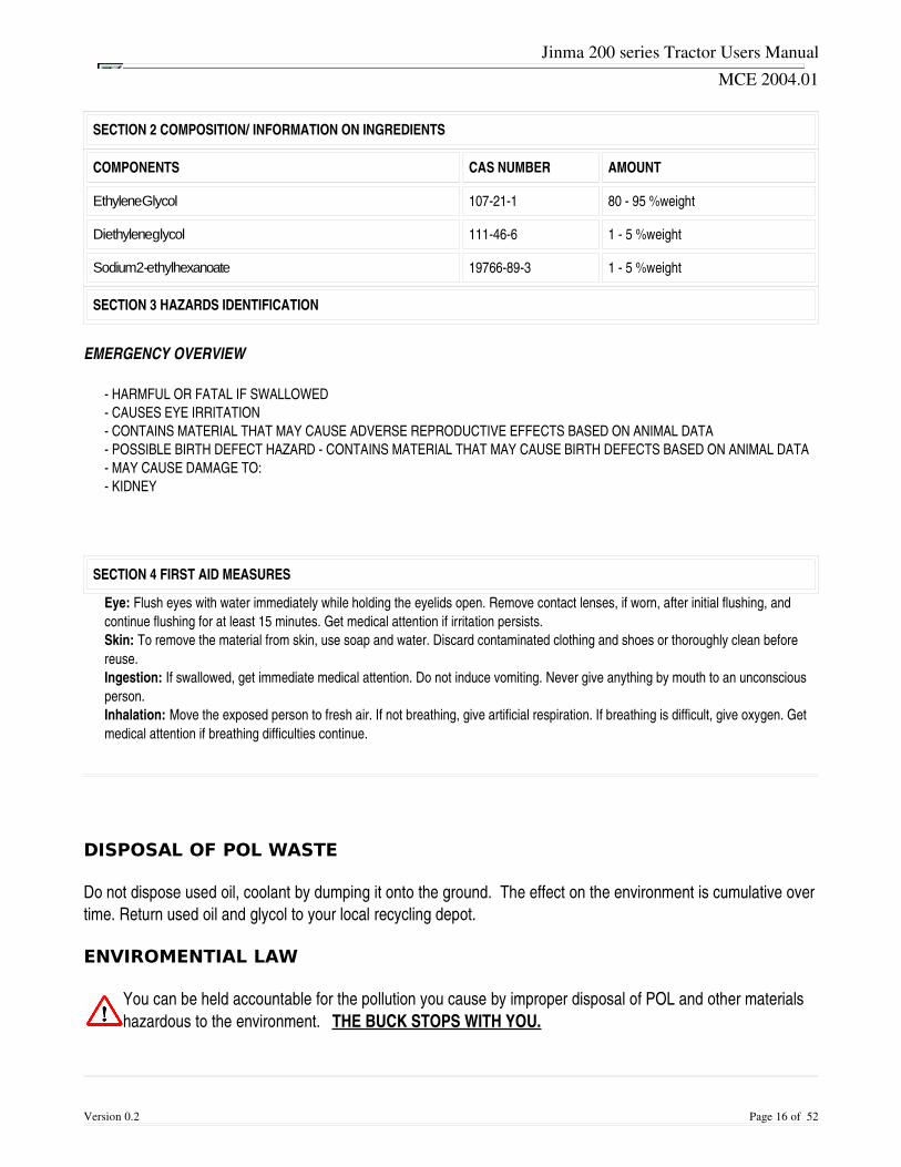
SECTION 2 COMPOSITION/ INFORMATION ON INGREDIENTS
COMPONENTS CAS NUMBER AMOUNT
Ethylene Glycol 107211 80 95 %weight
Diethylene glycol 111466 1 5 %weight
Sodium 2-ethylhexanoate 19766893 1 5 %weight
SECTION 3 HAZARDS IDENTIFICATION
EMERGENCY OVERVIEW
HARMFUL OR FATAL IF SWALLOWED CAUSES EYE IRRITATION CONTAINS MATERIAL THAT MAY CAUSE ADVERSE REPRODUCTIVE EFFECTS BASED ON ANIMAL DATA POSSIBLE BIRTH DEFECT HAZARD CONTAINS MATERIAL THAT MAY CAUSE BIRTH DEFECTS BASED ON ANIMAL DATA MAY CAUSE DAMAGE TO: KIDNEY
SECTION 4 FIRST AID MEASURES
Eye: Flush eyes with water immediately while holding the eyelids open. Remove contact lenses, if worn, after initial flushing, andcontinue flushing for at least 15 minutes. Get medical attention if irritation persists.Skin: To remove the material from skin, use soap and water. Discard contaminated clothing and shoes or thoroughly clean beforereuse.Ingestion: If swallowed, get immediate medical attention. Do not induce vomiting. Never give anything by mouth to an unconsciousperson.Inhalation: Move the exposed person to fresh air. If not breathing, give artificial respiration. If breathing is difficult, give oxygen. Getmedical attention if breathing difficulties continue.
DISPOSAL OF POL WASTE
Do not dispose used oil, coolant by dumping it onto the ground. The effect on the environment is cumulative overtime. Return used oil and glycol to your local recycling depot.
ENVIROMENTIAL LAW
You can be held accountable for the pollution you cause by improper disposal of POL and other materialshazardous to the environment. THE BUCK STOPS WITH YOU.
Version 0.2 Page 16 of 52
Jinma 200 series Tractor Users Manual
MCE 2004.01
Controls and Instruments
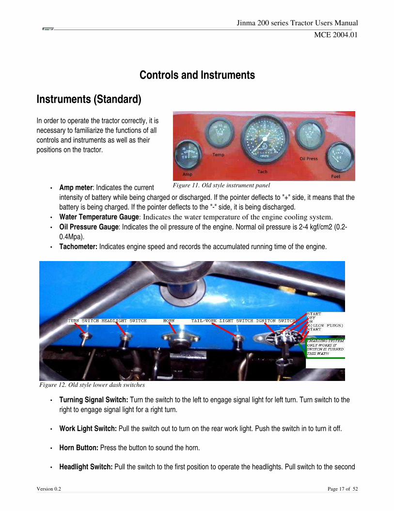
Instruments (Standard)
In order to operate the tractor correctly, it isnecessary to familiarize the functions of allcontrols and instruments as well as theirpositions on the tractor.
• Amp meter: Indicates the currentintensity of battery while being charged or discharged. If the pointer deflects to "+" side, it means that thebattery is being charged. If the pointer deflects to the "" side, it is being discharged.
• Water Temperature Gauge: Indicates the water temperature of the engine cooling system. • Oil Pressure Gauge: Indicates the oil pressure of the engine. Normal oil pressure is 24 kgf/cm2 (0.2
0.4Mpa). • Tachometer: Indicates engine speed and records the accumulated running time of the engine.
• Turning Signal Switch: Turn the switch to the left to engage signal light for left turn. Turn switch to theright to engage signal light for a right turn.
• Work Light Switch: Pull the switch out to turn on the rear work light. Push the switch in to turn it off.
• Horn Button: Press the button to sound the horn.
• Headlight Switch: Pull the switch to the first position to operate the headlights. Pull switch to the second
Version 0.2 Page 17 of 52
Figure 11. Old style instrument panel
Figure 12. Old style lower dash switches
Jinma 200 series Tractor Users Manual
MCE 2004.01
position to operate the headlights and taillights.
• Starting Switch: Turn to first notch clockwise, and power is supplied to the lights and charging system.This is the "on" position. Turn switch further clockwise,( you will feel spring tension,) to next notch, (youwill notice amp gage show discharge,) and hold for about 20 seconds to operate glow plugs in very coldweather. Turn switch full clockwise, and starter will engage to start engine. Release key when enginestarts. Use glow plugs only when temperature is freezing or below. Tractor may also be started by turningkey counterclockwise. This will start the tractor, but will not allow alternator system or lights to operate.This position should not be used in normal operation. NOTE: Clutch pedal must be pushed down all theway for starter to operate.
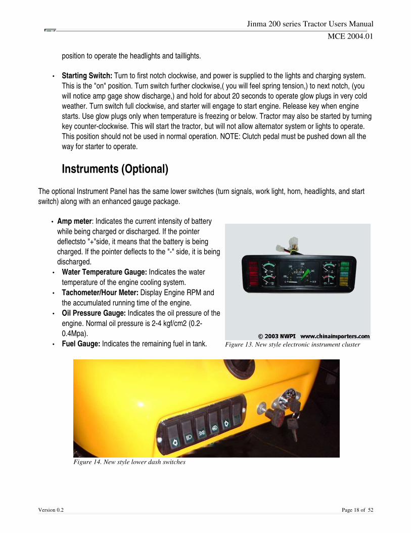
Instruments (Optional)
The optional Instrument Panel has the same lower switches (turn signals, work light, horn, headlights, and startswitch) along with an enhanced gauge package.
• Amp meter: Indicates the current intensity of batterywhile being charged or discharged. If the pointerdeflectsto "+"side, it means that the battery is beingcharged. If the pointer deflects to the "" side, it is beingdischarged.
• Water Temperature Gauge: Indicates the watertemperature of the engine cooling system.
• Tachometer/Hour Meter: Display Engine RPM andthe accumulated running time of the engine.
• Oil Pressure Gauge: Indicates the oil pressure of theengine. Normal oil pressure is 24 kgf/cm2 (0.20.4Mpa).
• Fuel Gauge: Indicates the remaining fuel in tank.
Version 0.2 Page 18 of 52
Figure 13. New style electronic instrument cluster
Figure 14. New style lower dash switches
Jinma 200 series Tractor Users Manual
MCE 2004.01
OPERATING CONTROLS
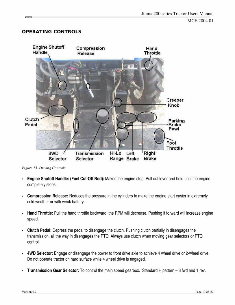
Figure 15. Driving Controls
• Engine Shutoff Handle: (Fuel CutOff Rod): Makes the engine stop. Pull out lever and hold until the enginecompletely stops.
• Compression Release: Reduces the pressure in the cylinders to make the engine start easier in extremelycold weather or with weak battery.
• Hand Throttle: Pull the hand throttle backward, the RPM will decrease. Pushing it forward will increase enginespeed.
• Clutch Pedal: Depress the pedal to disengage the clutch. Pushing clutch partially in disengages thetransmission, all the way in disengages the PTO. Always use clutch when moving gear selectors or PTOcontrol.
• 4WD Selector: Engage or disengage the power to front drive axle to achieve 4 wheel drive or 2wheel drive.Do not operate tractor on hard surface while 4 wheel drive is engaged.
• Transmission Gear Selector: To control the main speed gearbox. Standard H pattern – 3 fwd and 1 rev.
Version 0.2 Page 19 of 52
Jinma 200 series Tractor Users Manual
MCE 2004.01
• HiLo Range Gear Shifting Lever: To control the auxiliary speed gearbox. Pull up for hi range and down forlow range.
• Left and Right Brake Pedals: Move the braking lock plate right to lock both brake pedals together in order toapply both brakes at the same time. Separate the braking lock plate to achieve left or right oneside braking.This is used to make sharp turns.
• Foot Throttle Pedal: Depress the pedal down to increase engine speed.
• Parking Brake Lock Pawl: Use lever to lock pawl (located on the left brake pedal) to lock brakes in theapplied position (parking brake). Release brake lock pawl before moving tractor.
• Creeper Shifting Lever: To exchange the normal speed with the creeper speed range.
• Hydraulic Control Lever: When the lever is pulled backward the hitch is lifted. When pushed forward, thehitch is lowered. When moved into vertical position, the hitch is in neutral/hold position. Always return lever toneutral position when desired height of attachment is obtained.
• Differential Lock Lever: Used to engage or disengage differential lock. If disengaged the two driving wheelsmay have different speeds. If engaged, the two driving wheels operate at the same speed. Do not use on hardsurface or make turns.
• Hydraulic Speed Regulator: Used to control how fast or slow the hitch moves down.
• PTO Control Lever: Engage or disengage PTO power. Forward is 540 rpm, rearward is 1000 rpm.
Version 0.2 Page 20 of 52

Jinma 200 series Tractor Users Manual
MCE 2004.01
Control and Operation of the Tractor
Starting Engine
Before starting the engine, check fuel, lubricating oil and coolant level. Put gearshifting lever in neutral position.Note: The ignition switch must be in the ON position for the alternator to charge the battery.
Warm weather over 32 Degrees F
1. Turn the starting switch clockwise to "start" position. The starter drives the engine. The starter must not beoperated more than 510 seconds for each start. Only after an interval of at least 2 minutes should theengine be started again.
2. When the engine starts, release the key and it will return to the on position.
Cold weather below 32 Degrees F
Turn key clockwise to first position past "on" for approximately 20 seconds tooperate glow plugs. In this position, you will notice the amp gage will showdischarge. This will let you know that the glow plugs are operating. Thenproceed to start as in warm weather. In extreme cold conditions or if battery islow, you may use the decompression lever to ease starting.
Operating the Tractor
After the engine is started, run it at moderate speed for 510 minutes to allow the engine to warm up. After thewater temperature reaches 70 degrees Celsius the tractor can be operated by the following steps:
1. Lift any attached implements. 2. Depress the clutch pedal, put the gearshifting lever into the desired gear, and release the parking brake
lock pawl of the brake pedal. 3. Observe your environment make sure there are no obstructions or persons are in the way. 4. Gradually release clutch pedal and the tractor will start off smoothly. 5. During operation make sure all readings on gauges are indicating in the normal range. 6. DO NOT RIDE THE CLUTCH. Remove your foot from the clutch pedal when tractor is in motion.
Failure to do this will cause premature clutch failure.
Version 0.2 Page 21 of 52
Figure 16. Ignition Switch
Jinma 200 series Tractor Users Manual
MCE 2004.01
Driving the Tractor
1. When transiting between job sites or running on highway, lock the left and the right brake pedals togetherwith brake lock plate.
2. In field operation, oneside braking can be used to reduce turning radius. DO NOT use onesidebraking for sharp turning when the tractor is running at high speed or is being used for transportation onhighway. If onesided braking is used in these conditions, overturning and/or damage to components ispossible.
Proper speed should be selected for best productivity.
Stopping the Tractor
• Throttle the engine down to lower the speed of the tractor. • Depress the clutch pedal quickly and shift the gearshifting lever to neutral position. • Release the clutch pedal and let engine run at idle. • Depress the brake pedals to stop the tractor, then lock the pedals with the parking brake locking pawl.
Note: In case the tractor has to be stopped suddenly, clutch pedals and brake pedals should be ddepressed simultaneously. DO NOT depress the brake pedals only. Depression of only brake pedals will result in damage to the tractor.
• If the tractor is to be parked for quite a while, the engine should be stopped. After the engine has beenunloaded, it should run at low speed until the cooling water temperature drops to 70 degrees Celsius orlower. Pull out fuel cutoff rod to bring the engine to a stop.
Note: Never stop the engine when its temperature is very high. Do not stop the engine withdecompression mechanism.
• Turn the key switch to "O" (off) and remove key. If the tractor is going to be stored, turn off the fuel tankvalve.
Tractor Operation Safety
The following safety regulations are very important for protecting operator and tractor from hazards. They should must be strictly followed during operation.
• Carefully inspect the working condition of the engine and main components, and listen for any abnormalsound or noise. Be sure to check the adjustments of the clutch and brake. Check and tighten any loosenuts and bolts on main components of the tractor.
• Make sure there are no people or obstacles around the tractor before starting and operating tractor. • Do not get on or off the tractor while it is running. NEVER check, adjust or repair any part of tractor or
attachment with the engine running.
Version 0.2 Page 22 of 52

Jinma 200 series Tractor Users Manual
MCE 2004.01
• Before going up or down a slope, proper speed should be selected. Do not coast, turn sharply or shiftgears while driving down a slope.
• During transiting between job sites, lock the brake pedals together. Oneside braking should not be usedfor sharp turning when the tractor is running at high speed or with a full load.
• If front end of the tractor rises up in operation, throttle down the engine, disengage the clutch and reducethe load immediately to protect the tractor and operator from longitudinal overturning.
• If the engine runs away, immediately pull out the fuel cutoff rod, move decompression lever to"decompressing" position or plug up fresh air into the engine instead of disengaging clutch.
Diesel runaway can be caused be fuel oil dilution of the engine lube oil. If the engine runs away, find out why and repair the fault(s) before attempting to use themachine.
• Lighting equipment must be serviceable during operating at night or on public roads. • Transmission lever should be placed in the neutral position when the tractor is running idle. • Passengers should never be allowed to ride on tractor or attachments. • Never get under any implement or attachments while raised with hydraulic lift, with out first using safety
stands to support weight of attachment.
Control and Operation of PTO driven Devices
Control and Operation of PTO
PTO can be engaged and disengaged by using the PTO control lever on the right side of the transmission box.Push clutch pedal all the way down when engaging or disengaging PTO. To engage PTO, push down the controllever from the front and upper side for 1000 rpm and up for 740 rpm. To disengage, put the control lever in themiddle position. The operation steps are as follows:
• Unscrew the PTO safety shield and couple the desired driven machine to the PTO shaft. • Put the gearshifting lever at the neutral position. • Depress the clutch pedal fully then shift the PTO control lever to the proper "engaged" position. • Release the clutch pedal slowly and the driven machine will run. First let the driven machine run at slightly
open throttle to ensure that nothing is wrong with the driven machine. Then run with open throttle, and putthe driven machine into operation.
• Care should be taken when operating the PTO. On some attachments, the drive shaft may hit or come incontact with tractor or attachment when in the raised position.
Note: When the tractor implement travels for a long distance, the control lever should be shifted to the neutral position to cut off the power so as to avoid damaging the implement and causing physical damage.
Version 0.2 Page 23 of 52
Jinma 200 series Tractor Users Manual
MCE 2004.01
Control and Operation of Hydraulic Hitch System
The hydraulic hitch system serves to attach, lift and lower implement, as well as adjust and maintain the workingposition of the implement in order to meet different requirements of various implements and operations. To raiseand lower the implement, simply move the control lever of the distributor.
Depending on the type of work to be done, type of implement used and/or field conditions, the hydraulic hitchsystem provides various functions to obtain satisfactory work quality.
Position ControlThe position of the implement can be adjusted by moving the control lever of the distributor. Whenthe desired position of the implement has been obtained set the position of the stopper on the returnrod to limit the control lever. Tighten the stopper on the rod with the screw, so that the lever can bepushed to the same position every time. Adjustments may be made for different implements.
Floating ControlFloating control is suitable for field plowing. In floating control, the supporting wheel is needed for implement. During plowing, hold the control lever of distributor at "lowering" position (i.e. push the control lever of distributor forward with the return stopper. Do not return the control lever to the neutral position). The hydraulic circuit is then in "floating" control. Using floating control, the plowing depth is controlled by the change in height of the supporting wheel. The uniform plowing depth will be obtained in the field with changes of soilresistance.
Control of the Lowering Speed of the ImplementTurn the lowering speed adjusting valve to control the lowering speed of the implement. The lowering speed should be selected properly according to the weight of the implement and hardness of soil surface in order to prevent the implement from being seriously impacted anddamaged. To reduce the lowering speed, turn the lowering speed adjusting valve clockwise. To increase the lowering speed, turn the valve counterclockwise.
Operation of Hitch System
Adjust the implement according to the Implement Operation Manual before attaching the implements to the hitch system of the tractor. In plowing, adjust longitudinal and lateral level of plow in order to get the implement square to the ground.
Adjusting of Longitudinal LevelAdjust the length of the upper link of the hitch. Keep the plow frame horizontal in longitudinal level, so as to keep each share in the same plowing depth. If the front share plows deeper than the rear one, or heel of plow goes out from bottom of furrow, extend the upper link; if the front share plows shallower than the rear one, or rear heel sinks into the bottom of furrow, shorten the upper link.
Version 0.2 Page 24 of 52
Jinma 200 series Tractor Users Manual
MCE 2004.01
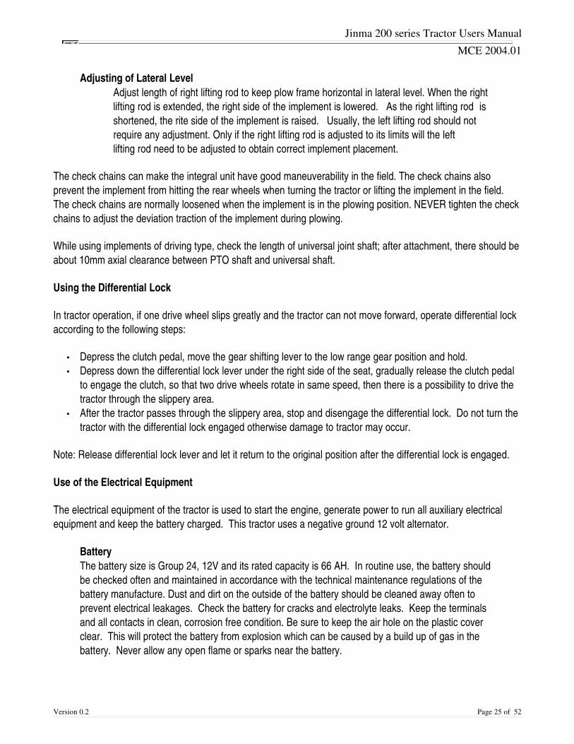
Adjusting of Lateral LevelAdjust length of right lifting rod to keep plow frame horizontal in lateral level. When the right lifting rod is extended, the right side of the implement is lowered. As the right lifting rod is shortened, the rite side of the implement is raised. Usually, the left lifting rod should not require any adjustment. Only if the right lifting rod is adjusted to its limits will the left lifting rod need to be adjusted to obtain correct implement placement.
The check chains can make the integral unit have good maneuverability in the field. The check chains alsoprevent the implement from hitting the rear wheels when turning the tractor or lifting the implement in the field.The check chains are normally loosened when the implement is in the plowing position. NEVER tighten the checkchains to adjust the deviation traction of the implement during plowing.
While using implements of driving type, check the length of universal joint shaft; after attachment, there should beabout 10mm axial clearance between PTO shaft and universal shaft.
Using the Differential Lock
In tractor operation, if one drive wheel slips greatly and the tractor can not move forward, operate differential lockaccording to the following steps:
• Depress the clutch pedal, move the gear shifting lever to the low range gear position and hold. • Depress down the differential lock lever under the right side of the seat, gradually release the clutch pedal
to engage the clutch, so that two drive wheels rotate in same speed, then there is a possibility to drive thetractor through the slippery area.
• After the tractor passes through the slippery area, stop and disengage the differential lock. Do not turn thetractor with the differential lock engaged otherwise damage to tractor may occur.
Note: Release differential lock lever and let it return to the original position after the differential lock is engaged.
Use of the Electrical Equipment
The electrical equipment of the tractor is used to start the engine, generate power to run all auxiliary electricalequipment and keep the battery charged. This tractor uses a negative ground 12 volt alternator.
BatteryThe battery size is Group 24, 12V and its rated capacity is 66 AH. In routine use, the battery shouldbe checked often and maintained in accordance with the technical maintenance regulations of thebattery manufacture. Dust and dirt on the outside of the battery should be cleaned away often toprevent electrical leakages. Check the battery for cracks and electrolyte leaks. Keep the terminalsand all contacts in clean, corrosion free condition. Be sure to keep the air hole on the plastic coverclear. This will protect the battery from explosion which can be caused by a build up of gas in thebattery. Never allow any open flame or sparks near the battery.
Version 0.2 Page 25 of 52

Jinma 200 series Tractor Users Manual
MCE 2004.01
The StarterKeep the starter clean and the wire connection lugs in clean and free of corrosion. Do not engagethe starter for longer than 10 seconds at any given time. The shortest interval between two attemptsat starting must be no less than 2 minutes. If the engine can not be started after several attempts,the trouble should be found and corrected. If the engine is started in cold weather, it should bepreheated with the block heater before starting.
Version 0.2 Page 26 of 52

Jinma 200 series Tractor Users Manual
MCE 2004.01
Maintenance Schedule for the Tractor
In order to keep the tractor in excellent condition, prolong its service life and reduce troubles, the users must oftencheck the mechanical condition of the tractor and strictly carry out recommended maintenance.
Daily Maintenance
1. Clean dirt and sludge on the tractor and implements. Under the extremely dusty circumstances, the airfilter should be cleaned more often.
2. Check all fastening bolts and nuts on the tractor, especially front and rear wheel nuts. Tighten ifnecessary.
3. Check the level in engine crankcase, radiator, fuel tank and hydraulic system; refill if necessary. Only afterthe engine has stopped for more than 15 minutes should the oil levels be checked.
4. Check for any leaking of oil, water, and repair if necessary. 5. Check the tire pressure and inflate if necessary.
50 Hour Maintenance (Every 50 Hours)
1. Carry out the maintenance items in daily maintenance. 2. All grease fittings should be wiped clean and greased with the recommended grease. 3. Check air filter and clean or replace as needed. 4. Check the fan belt tension (When pressing the middle part of the longer side of the belt, the belt drops
about 1525mm under the force of about 10N, then the tension is suitable). Adjust if necessary. 5. Check and adjust the free travel of clutch pedal and brake pedals. 6. Check the oil level in transmission box and front drive axle. Refill if necessary. 7. Wipe the battery with a piece of cloth. Check the electrolyte level. Smear the terminals with grease to
avoid corrosion.
250 Hour Maintenance (Every 250 Hours)
1. Complete daily and 50 hour maintenance items. 2. Change the engine oil and oil filter.
500 Hour Maintenance (Every 500 Hours)
1. Complete daily, 50 hour and 250 hour maintenance items. 2. Check and adjust inlet and exhaust valve clearance. 3. Clean fuel tank and fuel cartridge. 4. Flush transmission box. And replace lubricating oil. 5. Clean the filter of hydraulic lifter, check the oil for cleanliness. Flush the inside of lifter housing and
replace with fresh oil if necessary. 6. Check and adjust front wheel toein (The toein should be 410mm).
Version 0.2 Page 27 of 52

Jinma 200 series Tractor Users Manual
MCE 2004.01
1000 Hour Maintenance (Every 1000 Hours)
1. Complete daily, 50 hour, 250 hour, and, 500 hour maintenance. 2. Clean the gathered carbon in the silencer and exhaust manifold. 3. Clean the oil filter in the hydraulic lifting system, replace the oil in the system with fresh oil. 4. After the maintenance has been done, run the tractor for a short time for trial to make sure that every part
is in normal operating condition.
Maintenance for Long Term Storage
If the tractor is to be in long term storage, you should fully examine mechanical condition and follow the stepslisted below.
1. Store the tractor in dry shelter; support the front and rear wheels so weight is not on the tires. If storing inthe open air for limited time, cover the tractor with tarp.
2. Clean the outside of the tractor, wax painted surfaces and lubricate each lubrication point with grease. 3. Check antifreeze level and protection in the cooling system, remove the battery for storage and cover the
exhaust system to keep out all water and critters. 4. Start the engine to run for 20 minutes every three months to insure the proper lubrication of internal
engine parts.
Version 0.2 Page 28 of 52
Jinma 200 series Tractor Users Manual
MCE 2004.01
Tractor Adjustments
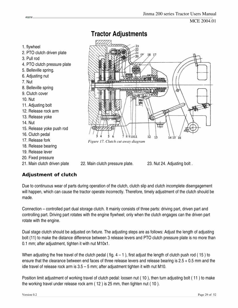
1. flywheel2. PTO clutch driven plate3. Pull rod4. PTO clutch pressure plate5. Belleville spring. 6. Adjusting nut 7. Nut 8. Belleville spring 9. Clutch cover 10. Nut 11. Adjusting bolt 12. Release rock arm 13. Release yoke 14. Nut 15. Release yoke push rod 16. Clutch pedal 17. Release fork 18. Release bearing 19. Release lever 20. Fixed pressure 21. Main clutch driven plate 22. Main clutch pressure plate. 23. Nut 24. Adjusting bolt .
Adjustment of clutch
Due to continuous wear of parts during operation of the clutch, clutch slip and clutch incomplete disengagementwill happen, which can cause the tractor operate incorrectly. Therefore, timely adjustment of the clutch should bemade.
Connection – controlled part dual storage clutch. It mainly consists of three parts: driving part, driven part andcontrolling part. Driving part rotates with the engine flywheel; only when the clutch engages can the driven partrotate with the engine.
Dual stage clutch should be adjusted on fixture. The adjusting steps are as follows: Adjust the length of adjustingbolt (11) to make the distance difference between 3 release levers and PTO clutch pressure plate is no more than0.1 mm; after adjustment, tighten it with nut M10x1.
When adjusting the free travel of the clutch pedal ( fig. 4 – 1 ), first adjust the length of clutch push rod ( 15 ) toensure that the clearance between end faces of three release levers and release bearing is 2.5 + 0.5 mm and theidle travel of release rock arm is 3.5 – 5 mm; after adjustment tighten it with nut M10.
Position limit adjustment of working travel of clutch pedal: loosen nut ( 10 ), then turn adjusting bolt ( 11 ) to makethe working travel under release rock arm ( 12 ) is 25 mm, then tighten nut ( 10 ).
Version 0.2 Page 29 of 52
Figure 17. Clutch cut away diagram
Jinma 200 series Tractor Users Manual
MCE 2004.01
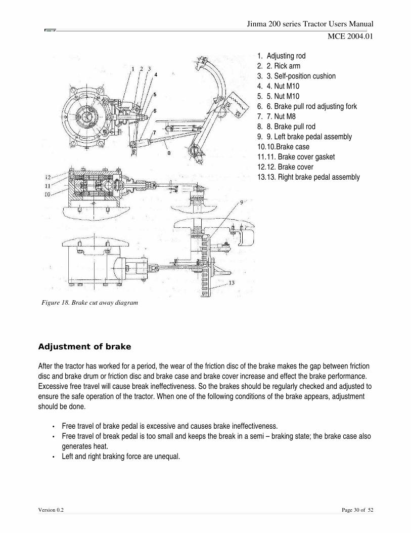
1. Adjusting rod2. 2. Rick arm 3. 3. Selfposition cushion 4. 4. Nut M10 5. 5. Nut M10 6. 6. Brake pull rod adjusting fork 7. 7. Nut M8 8. 8. Brake pull rod 9. 9. Left brake pedal assembly 10.10.Brake case 11.11. Brake cover gasket 12.12. Brake cover 13.13. Right brake pedal assembly
Adjustment of brake
After the tractor has worked for a period, the wear of the friction disc of the brake makes the gap between frictiondisc and brake drum or friction disc and brake case and brake cover increase and effect the brake performance.Excessive free travel will cause break ineffectiveness. So the brakes should be regularly checked and adjusted toensure the safe operation of the tractor. When one of the following conditions of the brake appears, adjustmentshould be done.
• Free travel of brake pedal is excessive and causes brake ineffectiveness. • Free travel of break pedal is too small and keeps the break in a semi – braking state; the brake case also
generates heat. • Left and right braking force are unequal.
Version 0.2 Page 30 of 52
Figure 18. Brake cut away diagram

Jinma 200 series Tractor Users Manual
MCE 2004.01
Adjustment of disc brake
Free state adjustment of disc brake
1. Loosen the outer locking nut M10 (5) on adjusting rod (1) 2. Turn the inner nut M10 (4) to change the mounting angle of the rock arm (2) through the longitudinal
motion of the shelf 3. Position cushion (3) and ensure the central connecting line of the upper and lower holes inclines to rear
from the plumb line. 4. After adjustment, lock it with locking nut (5).
Travel adjustment of brake pedal
1. Loosen the locking nut (7) on pull rod adjusting fork (6) 2. Pull brake pull rod adjusting fork to change the length of the pull rod (8) until the displacement (from the
highest position of the brake pedal to friction disc assembly being completely braked) of the brake pedalin 85 95 mm.
3. When the left right pedal are locked together, stepping on the pedals can simultaneously brake the leftand right wheels
4. After adjustment, lock it with nut (7).
If the above adjusting range can not perfectly make the free state and brake state out, they can be adjustedthrough increasing or reducing the brake cover gaskets (11) between brake cover (12) and brake case (10). If thebrake travel is too small, increase the gaskets; if the break travel is too big, reduce or remove the gaskets.
Version 0.2 Page 31 of 52
Jinma 200 series Tractor Users Manual
MCE 2004.01
Troubleshooting guide for Diesel Engines
Version 0.2 Page 32 of 52
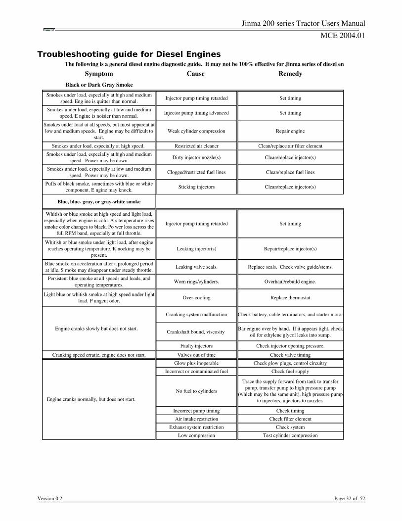
The following is a general diesel engine diagnostic guide. It may not be 100% effective for Jinma series of diesel engines.
Symptom Cause RemedyBlack or Dark Gray Smoke
Injector pump timing retarded Set timing
Injector pump timing advanced Set timing
Weak cylinder compression Repair engine
Smokes under load, especially at high speed. Restricted air cleaner Clean/replace air filter element
Dirty injector nozzle(s) Clean/replace injector(s)
Clogged/restricted fuel lines Clean/replace fuel lines
Sticking injectors Clean/replace injector(s)
Blue, blue gray, or graywhite smoke
Injector pump timing retarded Set timing
Leaking injector(s) Repair/replace injector(s)
Leaking valve seals. Replace seals. Check valve guide/stems.
Worn rings/cylinders. Overhaul/rebuild engine.
Overcooling Replace thermostat
Engine cranks slowly but does not start.
Cranking system malfunction Check battery, cable terminators, and starter motor
Crankshaft bound, viscosity
Faulty injectors Check injector opening pressure.
Cranking speed erratic, engine does not start. Valves out of time Check valve timing
Engine cranks normally, but does not start.
Glow plus inoperable Check glow plugs, control circuitry
Incorrect or contaminated fuel Check fuel supply
No fuel to cylinders
Incorrect pump timing Check timing
Air intake restriction Check filter element
Exhaust system restriction Check system
Low compression Test cylinder compression
Smokes under load, especially at high and medium speed. Eng ine is quitter than normal.
Smokes under load, especially at low and medium speed. E ngine is noisier than normal.
Smokes under load at all speeds, but most apparent at low and medium speeds. Engine may be difficult to
start.
Smokes under load, especially at high and medium speed. Power may be down.
Smokes under load, especially at low and medium speed. Power may be down.
Puffs of black smoke, sometimes with blue or white component. E ngine may knock.
Whitish or blue smoke at high speed and light load, especially when engine is cold. A s temperature rises smoke color changes to black. Po wer loss across the
full RPM band, especially at full throttle.
Whitish or blue smoke under light load, after engine reaches operating temperature. K nocking may be
present.
Blue smoke on acceleration after a prolonged period at idle. S moke may disappear under steady throttle.
Persistent blue smoke at all speeds and loads, and operating temperatures.
Light blue or whitish smoke at high speed under light load. P ungent odor.
Bar engine over by hand. If it appears tight, check oil for ethylene glycol leaks into sump.
Trace the supply forward from tank to transfer pump, transfer pump to high pressure pump
(which may be the same unit), high pressure pump to injectors, injectors to nozzles.
Jinma 200 series Tractor Users Manual
MCE 2004.01
Version 0.2 Page 33 of 52
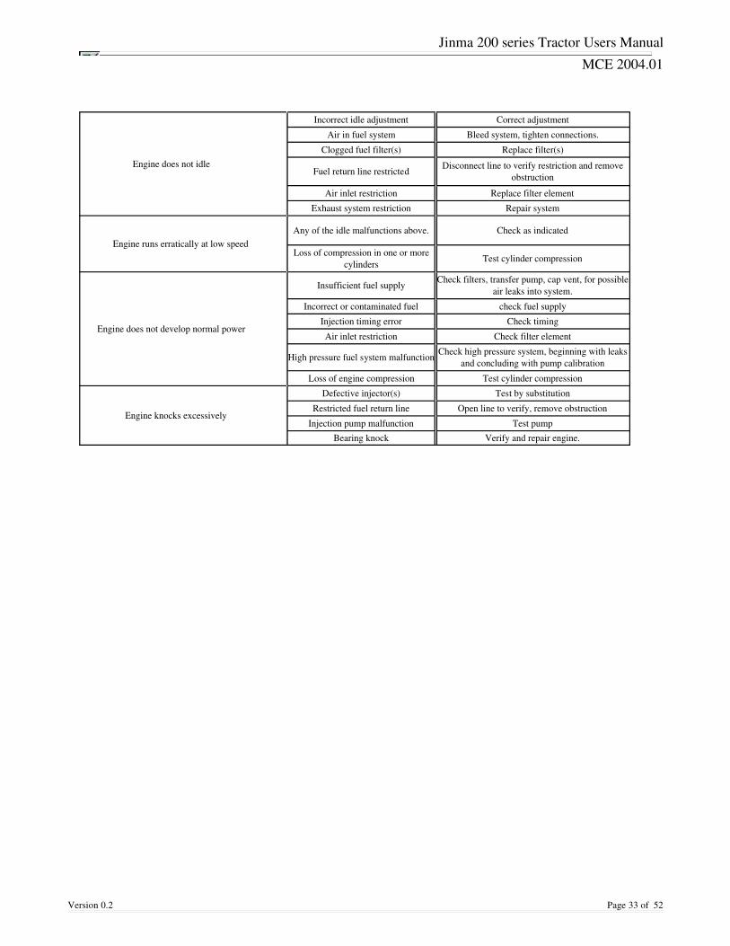
Engine does not idle
Incorrect idle adjustment Correct adjustment
Air in fuel system Bleed system, tighten connections.
Clogged fuel filter(s) Replace filter(s)
Fuel return line restricted
Air inlet restriction Replace filter element
Exhaust system restriction Repair system
Engine runs erratically at low speed Any of the idle malfunctions above. Check as indicated
Test cylinder compression
Engine does not develop normal power
Insufficient fuel supply
Incorrect or contaminated fuel check fuel supply
Injection timing error Check timing
Air inlet restriction Check filter element
High pressure fuel system malfunction
Loss of engine compression Test cylinder compression
Engine knocks excessively
Defective injector(s) Test by substitution
Restricted fuel return line Open line to verify, remove obstruction
Injection pump malfunction Test pumpBearing knock Verify and repair engine.
Disconnect line to verify restriction and remove obstruction
Loss of compression in one or more cylinders
Check filters, transfer pump, cap vent, for possible air leaks into system.
Check high pressure system, beginning with leaks and concluding with pump calibration
Jinma 200 series Tractor Users Manual
MCE 2004.01
SERVICE ADVISORIES
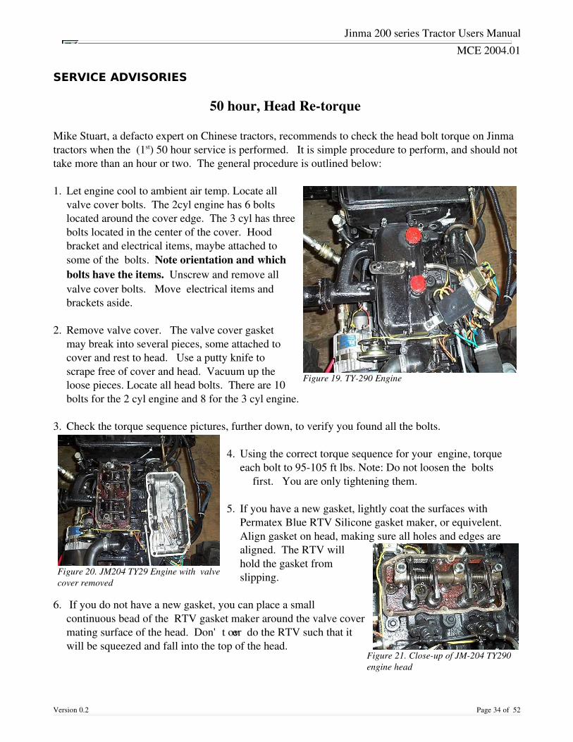
50 hour, Head Retorque Mike Stuart, a defacto expert on Chinese tractors, recommends to check the head bolt torque on Jinmatractors when the (1st) 50 hour service is performed. It is simple procedure to perform, and should nottake more than an hour or two. The general procedure is outlined below: 1. Let engine cool to ambient air temp. Locate all
valve cover bolts. The 2cyl engine has 6 boltslocated around the cover edge. The 3 cyl has threebolts located in the center of the cover. Hoodbracket and electrical items, maybe attached tosome of the bolts. Note orientation and whichbolts have the items. Unscrew and remove allvalve cover bolts. Move electrical items andbrackets aside.
2. Remove valve cover. The valve cover gasket may break into several pieces, some attached to cover and rest to head. Use a putty knife to scrape free of cover and head. Vacuum up the loose pieces. Locate all head bolts. There are 10bolts for the 2 cyl engine and 8 for the 3 cyl engine.
3. Check the torque sequence pictures, further down, to verify you found all the bolts. 4. Using the correct torque sequence for your engine, torque
each bolt to 95105 ft lbs. Note: Do not loosen the bolts first. You are only tightening them.
5. If you have a new gasket, lightly coat the surfaces with
Permatex Blue RTV Silicone gasket maker, or equivelent. Align gasket on head, making sure all holes and edges are aligned. The RTV will hold the gasket from slipping.
6. If you do not have a new gasket, you can place a smallcontinuous bead of the RTV gasket maker around the valve covermating surface of the head. Don't over do the RTV such that itwill be squeezed and fall into the top of the head.
Version 0.2 Page 34 of 52
Figure 20. JM204 TY29 Engine with valvecover removed
Figure 19. TY290 Engine
Figure 21. Closeup of JM204 TY290engine head
Jinma 200 series Tractor Users Manual
MCE 2004.01
7. Align the valve cover over the head. Carefully set it on the head. Use a couple of the valve coverbolts and just get them started, to keep the cover in position.
8. Get all valve cover bolts started. Make sure you have mounted any bracket or electrical items.
Tighten the valve cover bolts evenly. Start at the center, and work toward the ends. Don't have atorque spec for the valve cover bolts, but 3/8" socket wrench tight, should do.
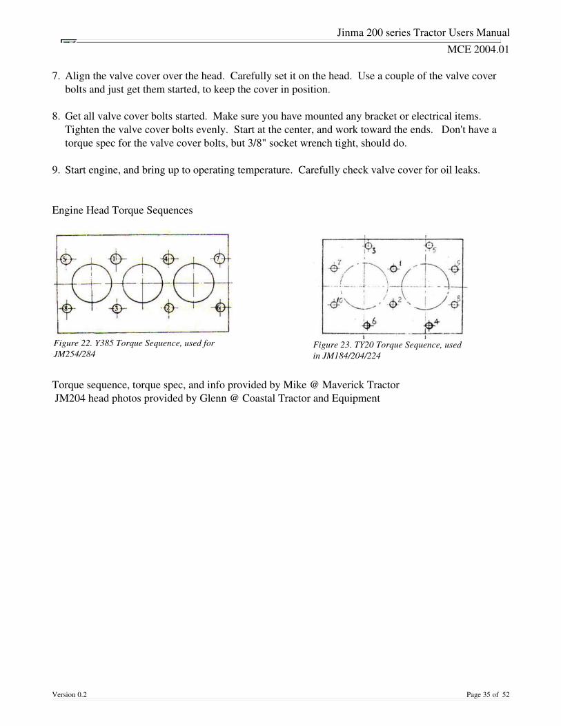
9. Start engine, and bring up to operating temperature. Carefully check valve cover for oil leaks. Engine Head Torque Sequences
Torque sequence, torque spec, and info provided by Mike @ Maverick Tractor JM204 head photos provided by Glenn @ Coastal Tractor and Equipment
Version 0.2 Page 35 of 52
Figure 22. Y385 Torque Sequence, used forJM254/284
Figure 23. TY20 Torque Sequence, usedin JM184/204/224
Jinma 200 series Tractor Users Manual
MCE 2004.01
Service Advisory 1: 1828 HP Jinma Tractor Hydraulic Fluid Intake Filter
Approximate Time Needed for Service is 1 hour.
Keeping the hydraulic pump prefilter clean is very important to the operation of your tractorshydraulic system. This filter is located under the drivers seat, feeds the pump that is located on the rightside of the engine which in turn produces pressure for the FEL, Power Steering, and 3 Point system.This pump is cooled and lubricated by the same oil it pumps and therefor a starvation of the pump dueto restricted flow will most likely cause complete failure or at the very least cause improper wear, earlyfailure and/or reduced pressure and flow. Indications that your filter is dirty would be either, no orsluggish loader or power steering operation especially during first start up or cold temperatures. Themanufacturing process can and will allow a significant amount of metal filings or contaminates to be inthe system. Just draining and replacing the oil will not clean the filter. It is our highestrecommendation that this bulletin be followed immediately before any further operation is attempted nomatter what hours are on the engine. Virtually no oil is lost during this procedure. The bulletin isspecifically written for the Q1828 and is not valid for the 3035 HP Jinma tractor See Advisory #2
1. If you have a front end loader make sure it is on the ground and no pressure is in the system. Withtractor turned off move all control valves back and forth to neutralize any pressure.
2. Remove the 4 bolts than hold down the operator seat assembly and remove the seat.
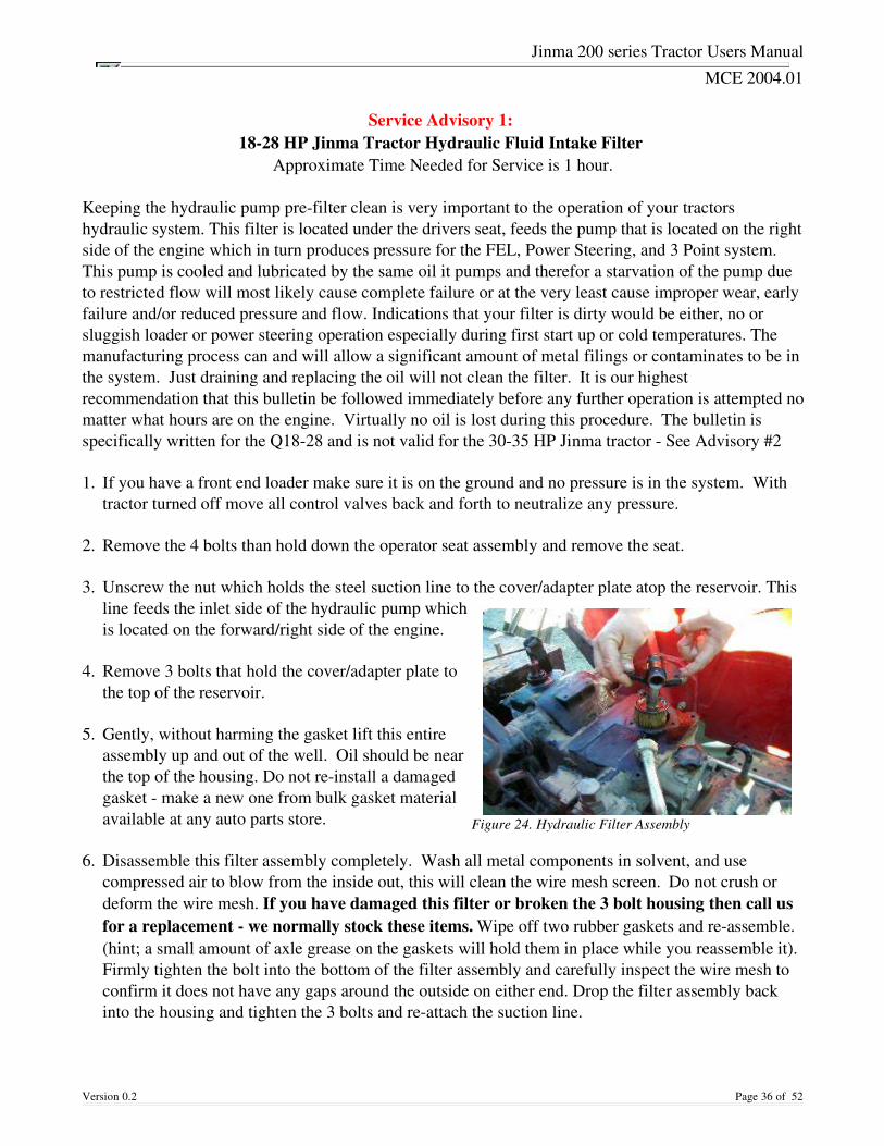
3. Unscrew the nut which holds the steel suction line to the cover/adapter plate atop the reservoir. Thisline feeds the inlet side of the hydraulic pump whichis located on the forward/right side of the engine.
4. Remove 3 bolts that hold the cover/adapter plate tothe top of the reservoir.
5. Gently, without harming the gasket lift this entireassembly up and out of the well. Oil should be nearthe top of the housing. Do not reinstall a damagedgasket make a new one from bulk gasket materialavailable at any auto parts store.
6. Disassemble this filter assembly completely. Wash all metal components in solvent, and usecompressed air to blow from the inside out, this will clean the wire mesh screen. Do not crush ordeform the wire mesh. If you have damaged this filter or broken the 3 bolt housing then call usfor a replacement we normally stock these items. Wipe off two rubber gaskets and reassemble. (hint; a small amount of axle grease on the gaskets will hold them in place while you reassemble it).Firmly tighten the bolt into the bottom of the filter assembly and carefully inspect the wire mesh toconfirm it does not have any gaps around the outside on either end. Drop the filter assembly backinto the housing and tighten the 3 bolts and reattach the suction line.
Version 0.2 Page 36 of 52
Figure 24. Hydraulic Filter Assembly
Jinma 200 series Tractor Users Manual
MCE 2004.01
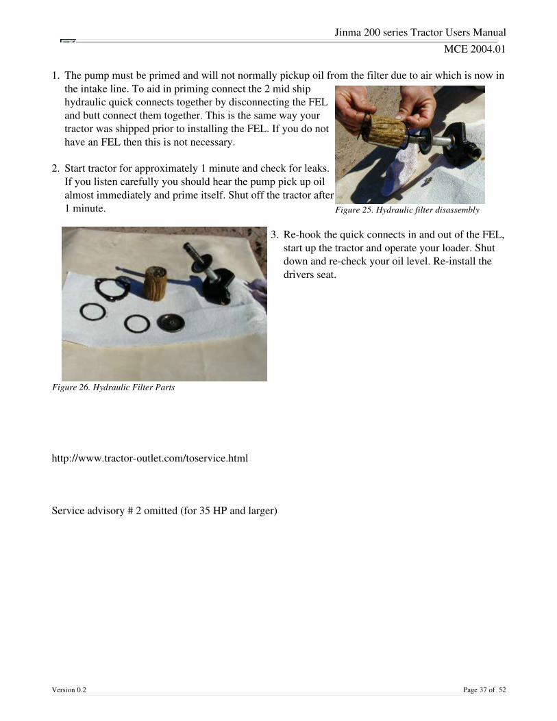
1. The pump must be primed and will not normally pickup oil from the filter due to air which is now inthe intake line. To aid in priming connect the 2 mid shiphydraulic quick connects together by disconnecting the FEL and butt connect them together. This is the same way yourtractor was shipped prior to installing the FEL. If you do nothave an FEL then this is not necessary.
2. Start tractor for approximately 1 minute and check for leaks.If you listen carefully you should hear the pump pick up oilalmost immediately and prime itself. Shut off the tractor after1 minute.
3. Rehook the quick connects in and out of the FEL,start up the tractor and operate your loader. Shutdown and recheck your oil level. Reinstall thedrivers seat.
http://www.tractoroutlet.com/toservice.html
Service advisory # 2 omitted (for 35 HP and larger)
Version 0.2 Page 37 of 52
Figure 26. Hydraulic Filter Parts
Figure 25. Hydraulic filter disassembly
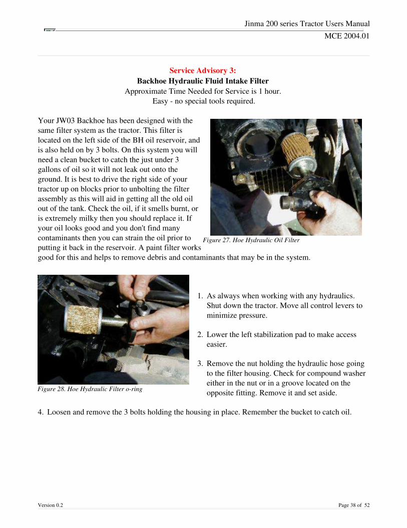
Jinma 200 series Tractor Users Manual
MCE 2004.01
Service Advisory 3: Backhoe Hydraulic Fluid Intake Filter
Approximate Time Needed for Service is 1 hour. Easy no special tools required.
Your JW03 Backhoe has been designed with thesame filter system as the tractor. This filter islocated on the left side of the BH oil reservoir, andis also held on by 3 bolts. On this system you willneed a clean bucket to catch the just under 3gallons of oil so it will not leak out onto theground. It is best to drive the right side of yourtractor up on blocks prior to unbolting the filterassembly as this will aid in getting all the old oilout of the tank. Check the oil, if it smells burnt, oris extremely milky then you should replace it. Ifyour oil looks good and you don't find manycontaminants then you can strain the oil prior toputting it back in the reservoir. A paint filter worksgood for this and helps to remove debris and contaminants that may be in the system.
1. As always when working with any hydraulics.Shut down the tractor. Move all control levers tominimize pressure.
2. Lower the left stabilization pad to make accesseasier.
3. Remove the nut holding the hydraulic hose goingto the filter housing. Check for compound washereither in the nut or in a groove located on theopposite fitting. Remove it and set aside.
4. Loosen and remove the 3 bolts holding the housing in place. Remember the bucket to catch oil.
Version 0.2 Page 38 of 52
Figure 27. Hoe Hydraulic Oil Filter
Figure 28. Hoe Hydraulic Filter oring
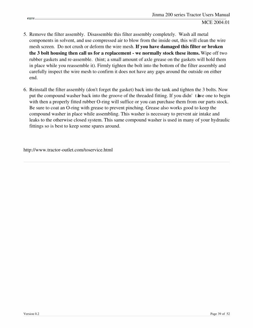
Jinma 200 series Tractor Users Manual
MCE 2004.01
5. Remove the filter assembly. Disassemble this filter assembly completely. Wash all metalcomponents in solvent, and use compressed air to blow from the inside out, this will clean the wiremesh screen. Do not crush or deform the wire mesh. If you have damaged this filter or brokenthe 3 bolt housing then call us for a replacement we normally stock these items. Wipe off tworubber gaskets and reassemble. (hint; a small amount of axle grease on the gaskets will hold themin place while you reassemble it). Firmly tighten the bolt into the bottom of the filter assembly andcarefully inspect the wire mesh to confirm it does not have any gaps around the outside on eitherend.
6. Reinstall the filter assembly (don't forget the gasket) back into the tank and tighten the 3 bolts. Nowput the compound washer back into the groove of the threaded fitting. If you didn't have one to beginwith then a properly fitted rubber Oring will suffice or you can purchase them from our parts stock.Be sure to coat an Oring with grease to prevent pinching. Grease also works good to keep thecompound washer in place while assembling. This washer is necessary to prevent air intake andleaks to the otherwise closed system. This same compound washer is used in many of your hydraulicfittings so is best to keep some spares around.
http://www.tractoroutlet.com/toservice.html
Version 0.2 Page 39 of 52

Jinma 200 series Tractor Users Manual
MCE 2004.01
Service Advisory 4: Injector Pump Oil
Approximate Time Needed for Service is 20 min. Easy no special tools required. http://www.tractoroutlet.com/toservice.html
You should check your fuel injection pump oil regularly and change it yearly. The oil is for splashlubrication of the steel balls and other moving parts inside the mechanical governor. We have foundthat hydraulic or engine oil is acceptable for use.
The fill plug (A) is toward the rear of the injector pump and is mounted on top with a breather. Thedrain (C) is on the bottom. Total oil volume is about 4 oz. or 1/4 of a pint if completely empty.
To fill and check, first remove the (A) breather on top, then remove the rubber cap (not alwaysincluded) from bottom of (B) and add oil very slowly, one ounce at a time. When oil comes out (B)then it is full. Wait a full 15 minutes for excess oil to run out prior to starting engine. Once oil hasstopped then replace rubber cap (B) and breather (A).
Version 0.2 Page 40 of 52
Figure 29. Fuel Injector Oil filler (A) & Drain (C) Figure 30. Fuel Injector Breather (A) and Cap (B)
Figure 32. Fuel Injector Steel Balls Figure 31. Fuel Injector Assembly

Jinma 200 series Tractor Users Manual
MCE 2004.01
Service Advisory 5: Oil Drains
Easy no special tools required.
Figure 33. Transmission Oil Drain Figure 34. Engine Oil Drain
Figure 35. Hydraulic System Oil Drain
Draining and Changing your oils is fairly straight forward and easy. Above we have shown you thedrain locations for each system. Your engine uses standard weight oils. We use HD 30 but 1040 andother weights will work also. Use what ever weight oil you are running in your vehicles which wouldbe appropriate for your local temperature conditions. The transmission and hydraulic system use thesame oil. Choose a quality hydraulic oil such as #303 from New Holland.
Version 0.2 Page 41 of 52
Jinma 200 series Tractor Users Manual
MCE 2004.01
Service Advisory 6: Ignition Switch Retrofit
Easy no special tools required. http://www.tractoroutlet.com/toservice.html
The ignition switch that came with your Jinma 1828 HP tractor is multifunction and can present someproblems after significant use. It can have intermittent faults where the momentary glow plugs andstarter are immediately on when you turn the key to the first position (lights). In other words, all threeposts are hot, #2 for lights, #3 for glow plugs, and #4 for starter solenoid. This will cause your 30 ampfuse to blow consistently. A replacement switch is available through your local New Holland dealer andwas used on Ford Series 20009000 tractors from about 1965 on. Ask for Ford Part # D 5NN11N501A.If you would still like to use a direct replacement that requires nothing other than wire for wireexchange then we normally stock them. Ask for Jinma part number #TY290
© Tractor Outlet
P.O. Box 147
83548 Bowens Lane
Christmas Valley, Oregon 97641
Version 0.2 Page 42 of 52
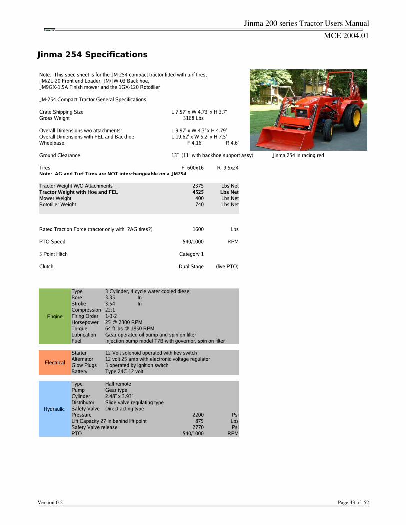
Jinma 200 series Tractor Users Manual
MCE 2004.01
Jinma 254 Specifications
Version 0.2 Page 43 of 52
Note: This spec sheet is for the JM 254 compact tractor fitted with turf tires,JM/ZL-20 Front end Loader, JM/JW-03 Back hoe,JM9GX-1.5A Finish mower and the 1GX-120 Rototiller
JM-254 Compact Tractor General Specifications
Crate Shipping Size L 7.57' x W 4.73' x H 3.7'Gross Weight 3168 Lbs
Overall Dimensions w/o attachments: L 9.97' x W 4.3' x H 4.79'Overall Dimensions with FEL and Backhoe L 19.62' x W 5.2' x H 7.5'Wheelbase F 4.16' R 4.6'
Ground Clearance Jinma 254 in racing red
Tires F 600x16 R 9.5x24Note: AG and Turf Tires are NOT interchangeable on a JM254
Tractor Weight W/O Attachments 2375 Lbs NetTractor Weight with Hoe and FEL 4525 Lbs NetMower Weight 400 Lbs NetRototiller Weight 740 Lbs Net
Rated Traction Force (tractor only with ?AG tires?) 1600 Lbs
PTO Speed 540/1000 RPM
3 Point Hitch Category 1
Clutch Dual Stage (live PTO)
Engine
Type 3 Cylinder, 4 cycle water cooled dieselBore 3.35 InStroke 3.54 InCompression 22:1Firing Order 1-3-2Horsepower 25 @ 2300 RPMTorque 64 ft lbs @ 1850 RPMLubrication Gear operated oil pump and spin on filterFuel Injection pump model T7B with governor, spin on filter
Electrical
Starter 12 Volt solenoid operated with key switchAlternator 12 volt 25 amp with electronic voltage regulatorGlow Plugs 3 operated by ignition switchBattery Type 24C 12 volt
Hydraulic
Type Half remotePump Gear typeCylinder 2.48” x 3.93”Distributor Slide valve regulating typeSafety Valve Direct acting typePressure 2200 PsiLift Capacity 27 in behind lift point 875 LbsSafety Valve release 2770 PsiPTO 540/1000 RPM
13” (11“ with backhoe support assy)
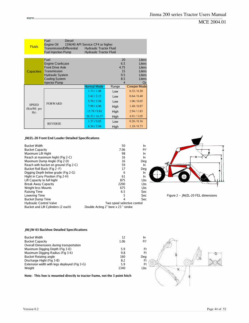
Jinma 200 series Tractor Users Manual
MCE 2004.01
Version 0.2 Page 44 of 52
Fluids
Fuel DieselEngine Oil 15W/40 API Service CF4 or higherTransmission/Differential Hydraulic Tractor FluidFuel Injection Pump Hydraulic Tractor Fluid
Capacities
Fuel 20 LitersEngine Crankcase 6.5 LitersFront Drive Axle 4.75 LitersTransmission 15 LitersHydraulic System 9.5 LitersCooling System 8.5 LitersInjector Pump 4 Oz
Normal Mode Range Creeper Mode
FORWARD
1.73 / 1.08 Low 0.32 / 0.20
3.42 / 2.13 Low 0.64 / 0.40
5.70 / 3.54 Low 1.06 / 0.65
7.99 / 4.96 High 1.40 / 0.87
15.79 / 9.81 High 2.94 / 1.83
26.35 / 16.37 High 4.91 / 3.05
REVERSE1.37 / 0.85 Low 0.26 / 0.16
6.34 / 3.94 High 1.18 / 0.73
JM/ZL-20 Front End Loader Detailed Specifications
Bucket Width 50 In Bucket Capacity 7.06Maximum Lift Hight 98 In Reach at maximum hight (Fig 2-C) 16 In Maximum Dump Angle (Fig 2-D) 16 DegReach with bucket on ground (Fig 2-C) 59 In Bucket Roll Back (Fig 2–F) 17 DegDigging Depth below grade (Fig 2-G) 6 In Hight in Carry Position (Fig 2-H) 61 In Lift Capacity to full hight 875 LbsBreak Away Capacity 2200 LbsWeight less Mounts 675 LbsRaising Time 6.5 SecLowering Time 5 Sec Figure 2 – JM/ZL-20 FEL dimensionsBucket Dump Time 4 SecHydraulic Control Valve Two spool selective controlBucket and Lift Cylinders (2 each) Double Acting 2” bore x 23 “ stroke
JM/JW-03 Backhoe Detailed Specifications
Bucket Width 12 In Bucket Capacity 1.06Overall Dimensions during transportationMaximum Digging Depth (Fig 3-E) 5.9 FtMaximum Digging Radius (Fig 3-K) 9.8 FtBucket Rotating angle 160 DegDischarge Hight (Fig 3-B) 8.2 FtExtension width with legs deployed (Fig 3-G) 5.9 FtWeight 1340 Lbs
Note: This hoe is mounted directly to tractor frame, not the 3 point hitch
SPEED(Km/Mi per
Hr)
Ft3
Ft3
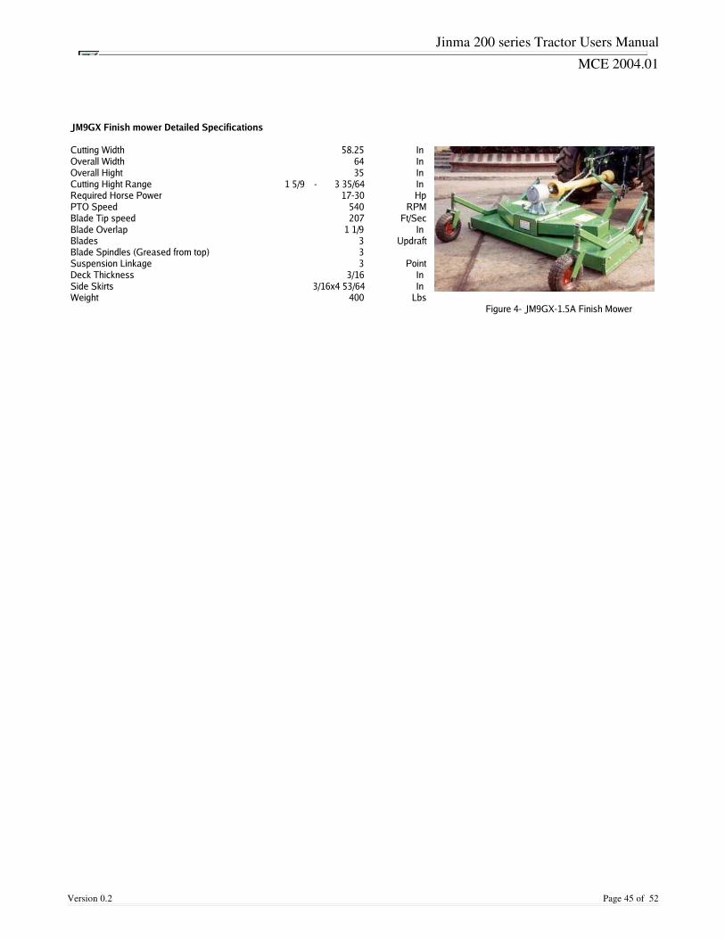
Jinma 200 series Tractor Users Manual
MCE 2004.01
Version 0.2 Page 45 of 52
JM9GX Finish mower Detailed Specifications
Cutting Width 58.25 In Overall Width 64 In Overall Hight 35 In Cutting Hight Range 1 5/9 - 3 35/64 In Required Horse Power 17-30 HpPTO Speed 540 RPMBlade Tip speed 207 Ft/SecBlade Overlap 1 1/9 In Blades 3 UpdraftBlade Spindles (Greased from top) 3Suspension Linkage 3 PointDeck Thickness 3/16 In Side Skirts 3/16x4 53/64 In Weight 400 Lbs
Figure 4- JM9GX-1.5A Finish Mower
Jinma 200 series Tractor Users Manual
MCE 2004.01
Jinma Crate Tractor Assembly
The Crate tractor assembly process can be broken down into 10 stages.
• All factory tractor, engine and accessory manuals. • Spare filters, lights, gaskets, tools and more • You will need; 1 gallon antifreeze, 2 gallons electrolyte, jack and stands / blocks, crescent
wrench, good wire cutters (the tractor and parts are held in place by bolts and lots of wire),a safe work area and diesel. Save all bolts, nuts and washers as you take the crate apart.You may be able to use them.
Each of the 10 stages has an estimated operation time of one hour. For assembled Tractors please see Jinma Page.
Stage
Description
1 Unpack crate, check contents, read manuals and fill battery with electrolyte.
2 Check tire pressure. Move tractor chassis from crate and bolt on 4 wheels.
3 Attach rear fenders, roll bar and seat belt anchor points.
4 Attach front weight frame. Insert battery.
5Attach fuel tank. Connect electrical connections and cables. (SeeTractorConnection wiring guide)
6 Attach engine exhaust, hood and steering wheel.
7 Attach 3 point linkage trailing arms and top link.
8Apply grease, lubricants and coolant. Fill fuel tank with diesel. Check all boltsfor tightness and fluid connections for leaks.
9 Connect battery terminals, prime injector pump, start engine.
10 Check operation and for leaks.
Version 0.2 Page 46 of 52
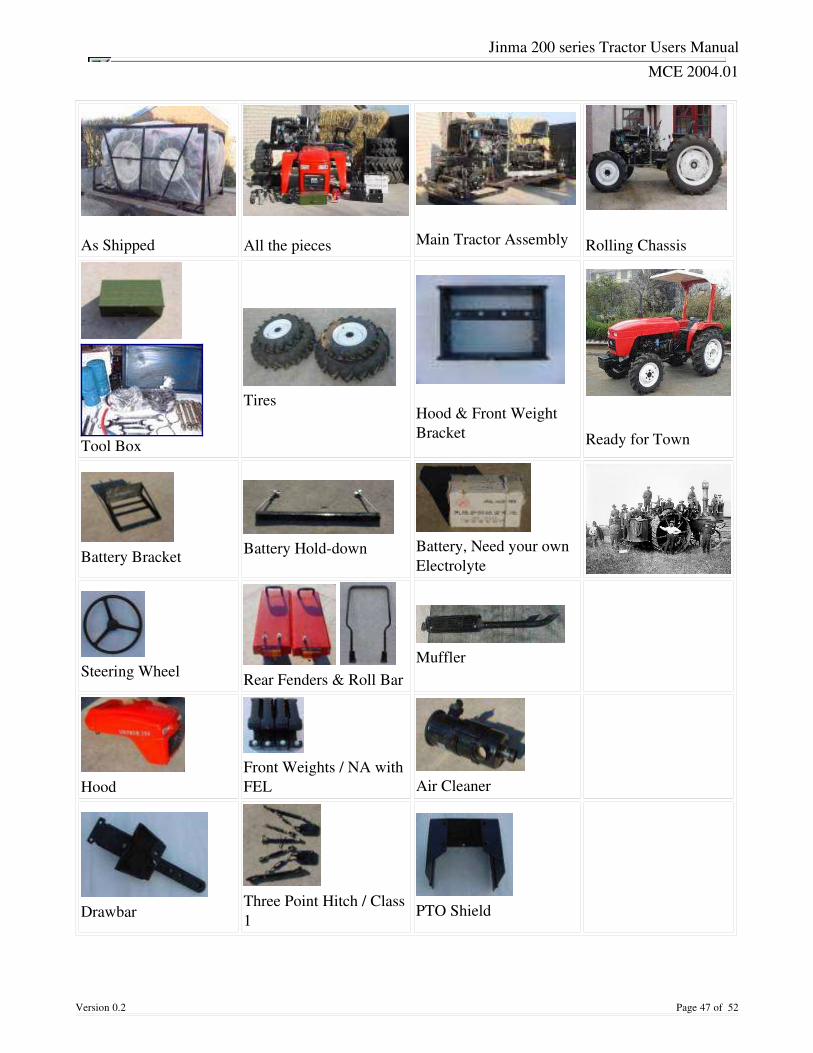
Jinma 200 series Tractor Users Manual
MCE 2004.01
As Shipped
All the pieces Main Tractor Assembly Rolling Chassis
Tool Box
Tires
Hood & Front WeightBracket Ready for Town
Battery Bracket
Battery Holddown
Battery, Need your ownElectrolyte
Steering Wheel
Rear Fenders & Roll Bar
Muffler
Hood
Front Weights / NA withFEL
Air Cleaner
Drawbar
Three Point Hitch / Class1
PTO Shield
Version 0.2 Page 47 of 52
Jinma 200 series Tractor Users Manual
MCE 2004.01
Before you start assembling your “C rate” tractor, please take some time to look over the owners manual and illustrated parts manual that is in the Blue “ tool and spare parts” box. Decades of hands on work on foreign equipment has taught me some rules that I would like to pass along.
• Positive Mental Attitude
• Do not be looking for “ problems” b ecause it is Chinese. Most tractors arrive with none and the minor ones you encounter are NORMAL for any new equipment.
• Part A was scratched in shipment!!!
• Brand name Orange, Green and Blue tractors are assembled from “ Crate” parts and minor imperfections are repaired and the tractor is sent to a dealer. A traditional dealer inspects the tractor and fixes any additional operational, fit and finish defects before the customer sees the equipment. You are the DEALER AND ASSEMBLY FACILITY. This is part of why you are saving a LOT of money. A missing bolt, a bent line or a scratch are items you will take care of for your customer (YOU) to make sure that his machine is as good asit can be.
• Don't overlook the small stuff
• Take your time assembling and checking your tractor. The more items you check during assembly the fewer problems you will have later. Check that the bolts everywhere are tight. A wire tie to secure hoses and wires now means less leaks and electrical problems for the life of your tractor.
• The D*@N *%@~ does not work!
Relax. I know the frustration after waiting so long for your tractor to arrive when something does not work or is really broken.
• If it does not work have you read the owners manual? It may have bad English but it doeshave good trouble shooting help.
• Defective Parts have a factory one year parts warranty. If we do not have the parts in stockwe may,
• Buy part from another dealer. Repair your part.
Get part from factory.
You will get your tractor running.
Version 0.2 Page 48 of 52

Jinma 200 series Tractor Users Manual
MCE 2004.01
I can't stress enough that you should relax, take your time, read and look at the pictures inthe parts and owners manuals and have fun. Get help when you need it and DO IT SAFE. Whenyou are done you will know more about your tractor than most owners and some DEALERS. Ihope you will have pride in knowing that the best assembly facility put your tractor together.
Copyright © 2002 Nelson Equipment Corporation Nelson Equipment Corporation 38544 Hwy. 99W Corvallis, OR 97330 Phone 5417455589 Fax: 5417455589 EMAIL: [email protected]
Version 0.2 Page 49 of 52
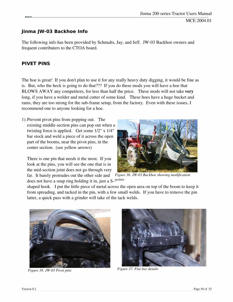
Jinma 200 series Tractor Users Manual
MCE 2004.01
Jinma JW-03 Backhoe Info
The following info has been provided by Schmalts, Jay, and Jeff. JW03 Backhoe owners andfrequent contributers to the CTOA board.
PIVET PINS
The hoe is great! If you don't plan to use it for any really heavy duty digging, it would be fine asis. But, who the heck is going to do that??? If you do these mods you will have a hoe thatBLOWS AWAY any competitors, for less than half the price. These mods will not take verylong, if you have a welder and metal cutter of some kind. These hoes have a huge bucket andrams, they are too strong for the subframe setup, from the factory. Even with these issues, Irecommend one to anyone looking for a hoe. 1).Prevent pivot pins from popping out. The
existing middle section pins can pop out when atwisting force is applied. Get some 1/2" x 1/4"bar stock and weld a piece of it across the openpart of the booms, near the pivot pins, in thecenter section. (see yellow arrows)
There is one pin that needs it the most. If youlook at the pins, you will see the one that is inthe midsection joint does not go through veryfar. It barely protrudes out the other side anddoes not have a snap ring holding it in, just a Sshaped hook. I put the little piece of metal across the open area on top of the boom to keep itfrom spreading, and tacked in the pin, with a few small welds. If you have to remove the pinlatter, a quick pass with a grinder will take of the tack welds.
Version 0.2 Page 50 of 52
Figure 36. JW03 Backhoe showing modificationpoints
Figure 37. Flat bar detailsFigure 38. JW03 Pivot pins
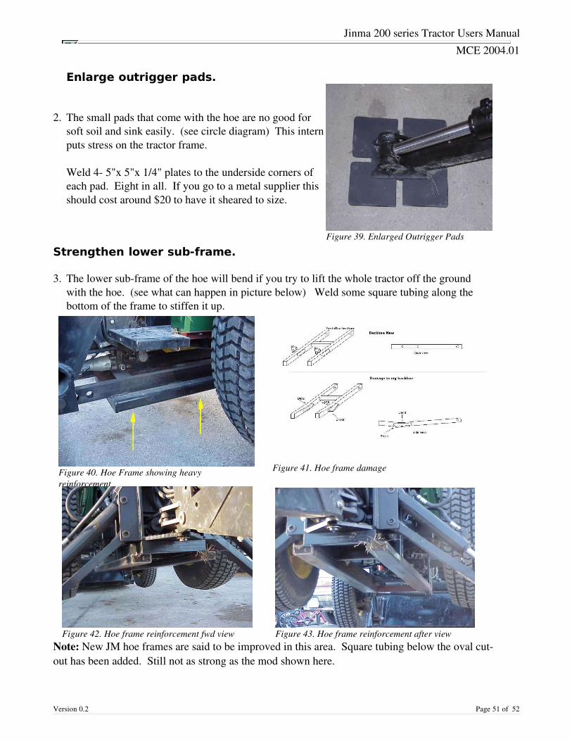
Jinma 200 series Tractor Users Manual
MCE 2004.01
Enlarge outrigger pads.
2. The small pads that come with the hoe are no good for
soft soil and sink easily. (see circle diagram) This internputs stress on the tractor frame.
Weld 4 5"x 5"x 1/4" plates to the underside corners ofeach pad. Eight in all. If you go to a metal supplier thisshould cost around $20 to have it sheared to size.
Strengthen lower sub-frame.
3. The lower subframe of the hoe will bend if you try to lift the whole tractor off the groundwith the hoe. (see what can happen in picture below) Weld some square tubing along thebottom of the frame to stiffen it up.
Note: New JM hoe frames are said to be improved in this area. Square tubing below the oval cutout has been added. Still not as strong as the mod shown here.
Version 0.2 Page 51 of 52
Figure 39. Enlarged Outrigger Pads
Figure 41. Hoe frame damageFigure 40. Hoe Frame showing heavyreinforcement
Figure 42. Hoe frame reinforcement fwd view Figure 43. Hoe frame reinforcement after view

Jinma 200 series Tractor Users Manual
MCE 2004.01
Stiffen up rear mount
4. Make a link that goes to the upper 3pt link.Great job! This guy can start his ownImplement company!
CreditsThe following info has been provided by Schmalts, Jay, and Jeff, JW03 Backhoe owners andfrequent contributers to the CTOA board.
Version 0.2 Page 52 of 52
Figure 44. Hoe frame top link stabilizer