JFA connector J1000 Series
9
Specifications ––––––––––––––––––– •Current rating: •Voltage rating: 125 V AC, DC/ J1100 250 V AC, DC/ J1800 •Temperature range: -55°C to +105°C (including temperature rise in applying electrical current) •Applicable wire: AWG #28 to #18 •Applicable PC board thickness: 1.6 mm *In using the products, refer to "Handling Precaution for Terminal and Connector" described on our website (Technical documents of Product information page). *Contact JST for details. *RoHS2 compliance. Standards –––––––––––––––––––––– 0 Recognized E60389 1 JFA CONNECTOR J1000 SERIES 2.2mm pitcth/Disconnectable Crimp style connectors(Wire-to-board/Wire-to-wire) • Double-spring construction • Up to AWG #18 with 2.2 mm pitch • Housing lance • Secure locking method • Recognition mark Wire size (AWG) #18 6.4 5.5 5.5 4.7 4.0 3.9 3.6 3.6 Circuits 3 6 8 12 20 22 26 30 #20 5.4 4.6 4.6 3.9 3.4 3.3 3.0 3.0 #22 4.8 4.0 4.0 3.4 3.0 2.9 2.6 2.6 #24 4.0 3.4 3.1 2.7 2.4 2.3 2.2 2.1 #26 3.4 2.9 2.6 2.3 2.0 1.9 1.8 1.7 #28 2.8 2.4 2.2 2.0 1.8 1.7 1.6 1.5 Unit: (A) Connectors for signal circuit or power supply circuit, applicable to the factory automation, heavy electric machinery, and other industrial equipment in general. In spite of various kinds of housings available, their contacts are designed to be common. The applicable tooling can be standardized.
Transcript of JFA connector J1000 Series
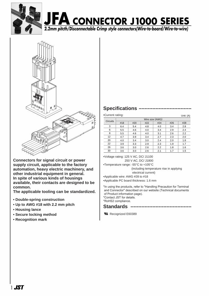
Specifications –––––––––––––––––––•Current rating:
•Voltage rating: 125 V AC, DC/ J1100250 V AC, DC/ J1800
•Temperature range: -55°C to +105°C(including temperature rise in applying electrical current)
•Applicable wire: AWG #28 to #18•Applicable PC board thickness: 1.6 mm
*In using the products, refer to "Handling Precaution for Terminal and Connector" described on our website (Technical documents of Product information page).
*Contact JST for details.*RoHS2 compliance.
Standards ––––––––––––––––––––––0 Recognized E60389
1
JFA CONNECTOR J1000 SERIES2.2mm pitcth/Disconnectable Crimp style connectors(Wire-to-board/Wire-to-wire)
• Double-spring construction• Up to AWG #18 with 2.2 mm pitch• Housing lance• Secure locking method• Recognition mark
Wire size (AWG)
#186.45.55.54.74.03.93.63.6
Circuits
3 6 81220222630
#205.44.64.63.93.43.33.03.0
#224.84.04.03.43.02.92.62.6
#244.03.43.12.72.42.32.22.1
#26�3.4�2.9�2.6�2.3�2.0�1.9�1.8�1.7
#282.82.42.22.01.81.71.61.5
Unit: (A)
Connectors for signal circuit or powersupply circuit, applicable to the factoryautomation, heavy electric machinery, andother industrial equipment in general.In spite of various kinds of housingsavailable, their contacts are designed to becommon.The applicable tooling can be standardized.
2
JFA CONNECTOR/J1000 SERIES
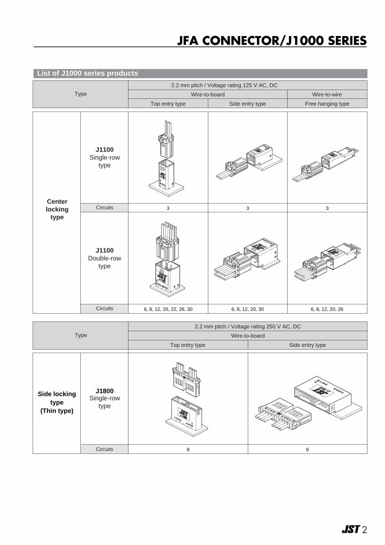
J1100Single-row
type
CircuitsCenterlocking
type3 3 3
Type Wire-to-board
Top entry type Side entry type Free hanging type
2.2 mm pitch / Voltage rating 125 V AC, DC
Wire-to-wire
J1800Single-row
type
88
Type
Top entry type Side entry type
2.2 mm pitch / Voltage rating 250 V AC, DC
Wire-to-board
J1100Double-row
type
Circuits
Circuits
6, 8, 12, 20, 22, 26, 30 6, 8, 12, 20, 30 6, 8, 12, 20, 26
Side lockingtype
(Thin type)
List of J1000 series products
3
JFA CONNECTOR/J1000 SERIES
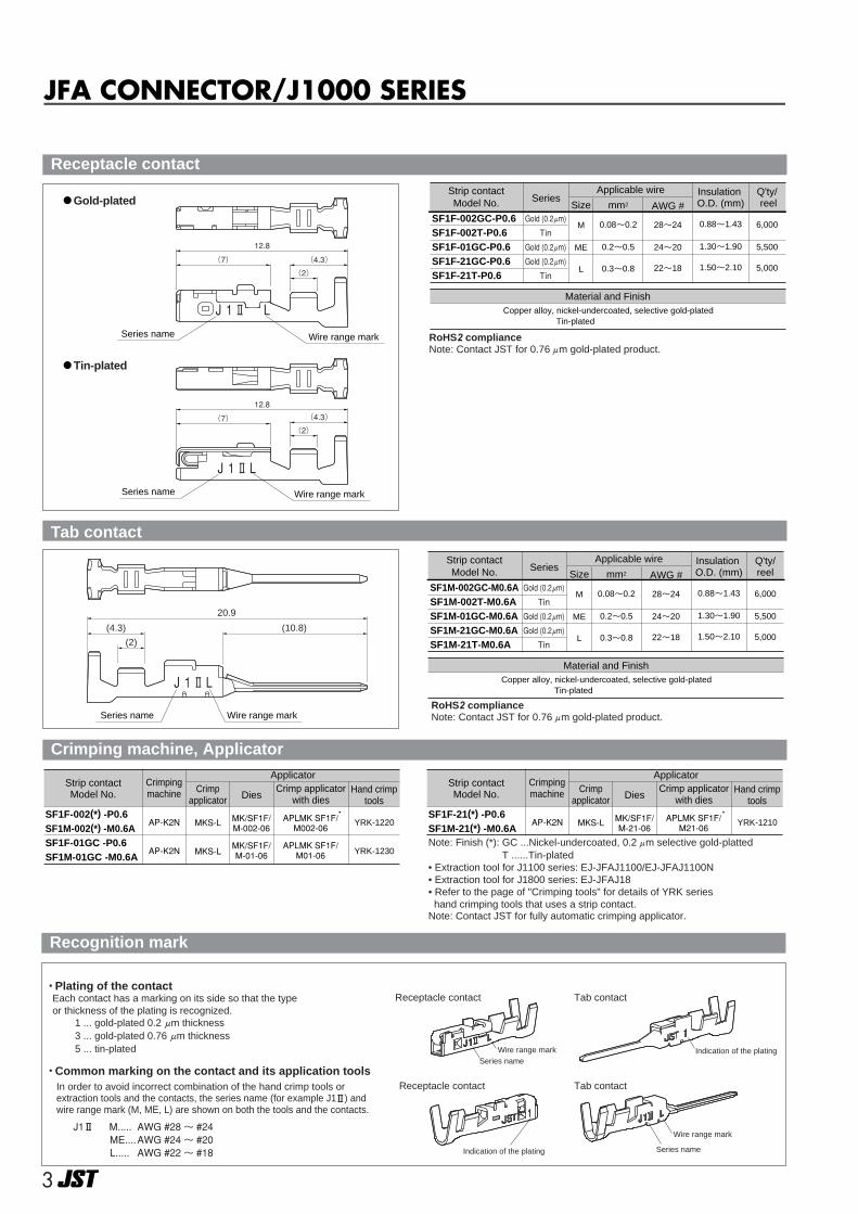
Series name Wire range mark
Ⅱ LJ 1
20.9
(10.8)(4.3)
(2)
Material and FinishCopper alloy, nickel-undercoated, selective gold-plated
Tin-plated
mm2SizeSeries
Strip contactModel No. AWG #
Insulation O.D. (mm)
Applicable wire Q'ty/ reel
SF1F-002GC-P0.6SF1F-002T-P0.6SF1F-01GC-P0.6SF1F-21GC-P0.6SF1F-21T-P0.6
0.08~0.2
0.2~0.5
0.3~0.8
M
ME
L
28~24
24~20
22~18
0.88~1.43
1.30~1.90
1.50~2.10
6,000
5,500
5,000
Gold (0.2μm)
Tin
Gold (0.2μm)
Gold (0.2μm)
Tin
Material and FinishCopper alloy, nickel-undercoated, selective gold-plated
Tin-plated
mm2SizeSeries
Strip contactModel No. AWG #
Insulation O.D. (mm)
Applicable wire Q'ty/reel
SF1M-002GC-M0.6ASF1M-002T-M0.6ASF1M-01GC-M0.6ASF1M-21GC-M0.6ASF1M-21T-M0.6A
0.08~0.2
0.2~0.5
0.3~0.8
M
ME
L
28~24
24~20
22~18
0.88~1.43
1.30~1.90
1.50~2.10
6,000
5,500
5,000
Gold (0.2μm)
Tin
Gold (0.2μm)
Gold (0.2μm)
Tin
Gold-plated
Tin-plated
Wire range mark
Wire range mark
Series name
Series name
Ⅱ LJ 1
(4.3)
12.8
(7)
(2)
Ⅱ LJ 1
12.8
(4.3)(7)
(2)
Crimpingmachine
ApplicatorHand crimp
tools
YRK-1220
YRK-1230
DiesCrimp applicator
with diesCrimp
applicator
APLMK SF1F/ M002-06
APLMK SF1F/ M01-06
MK/SF1F/ M-002-06
MK/SF1F/ M-01-06
MKS-L
MKS-L
AP-K2N
AP-K2N
SF1F-002(*) -P0.6SF1M-002(*) -M0.6ASF1F-01GC -P0.6SF1M-01GC -M0.6A
Strip contactModel No.
Crimpingmachine
ApplicatorHand crimp
tools
YRK-1210
DiesCrimp applicator
with diesCrimp
applicator
APLMK SF1F/ M21-06
MK/SF1F/ M-21-06
MKS-LAP-K2NSF1F-21(*) -P0.6SF1M-21(*) -M0.6A
Strip contactModel No.
Receptacle contact
RoHS2 compliance Note: Contact JST for 0.76μm gold-plated product.
Tab contact
RoHS2 compliance Note: Contact JST for 0.76μm gold-plated product.
Crimping machine, Applicator
Plating of the contact
Common marking on the contact and its application tools
Indication of the plating
Indication of the plating
Receptacle contact Tab contact
Receptacle contact Tab contact
Each contact has a marking on its side so that the type or thickness of the plating is recognized. 1 ... gold-plated 0.2 μm thickness 3 ... gold-plated 0.76 μm thickness 5 ... tin-plated
In order to avoid incorrect combination of the hand crimp tools or extraction tools and the contacts, the series name (for example J1 ) and wire range mark (M, ME, L) are shown on both the tools and the contacts.
J1 M..... AWG #28 ~ #24 ME.... AWG #24 ~ #20L..... AWG #22 ~ #18
Series nameWire range mark
Series name
Wire range mark
Recognition mark
Note: Finish (*): GC ...Nickel-undercoated, 0.2μm selective gold-plattedT ......Tin-plated
• Extraction tool for J1100 series: EJ-JFAJ1100/EJ-JFAJ1100N• Extraction tool for J1800 series: EJ-JFAJ18• Refer to the page of "Crimping tools" for details of YRK serieshand crimping tools that uses a strip contact.
Note: Contact JST for fully automatic crimping applicator.
4
J1000 SERIES/J1100
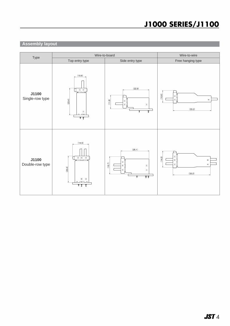
Top entry type Side entry type Free hanging type
J1100Double-row type
(33.2)
(10.6)
(10.6)
(23.4)
(11.8)
(22.9)
(33.2)
(14.5)
(14.5)
(23.4)
(15.7)
(25.1)
A
X A
A
X
A
A
X
A
AX B
B A
A
X
B
A
B
BAA
X
B
J1100Single-row type
TypeWire-to-board Wire-to-wire
Assembly layout
55
<Single-row type>
Keying No.
Line No.
Series name
Circuit No.
�PC board layout (Reference)(viewed from component side)
(2.4)(0.6)
2±0.05
(B)
(19)
3.3
(0.6)83.1
19BA
8.4
9.6
A
X
321
1±0.1
φ1±0.05
A±0.052.2±0.05
8±0.05
2.2
Connector outline
<Single-row type>
�PC board layout (Reference)(viewed from component side)
Line No.
Series name
Circuit No.
Keying No.
Connector outline
X
321
A
(2.4)A±0.05
2.7±0.05
1±0.1
(B)
2.2±0.05
(8.4)
3.619.5
2.7
3.2
B
A
2.2
8.4
2±0.05
φ1±0.05
(2.5)
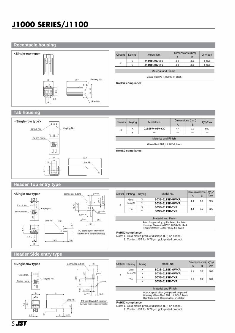
Material and Finish
Glass-filled PBT, UL94V-0, black
34.4
4.4
8.0
8.0
1,200
1,200
X
Y
J11SF-03V-KXJ11SF-03V-KY
Dimensions (mm)Circuits Keying Model No.
A BQ’ty/box<Single-row type>
Line No.
Keying No.
X
A
2.2
(11.3)
16.7
6.6
B
A
Material and Finish
Glass-filled PBT, UL94V-0, black
34.4
—
9.2
—
500
—
X
Y
J11SFM-03V-KX—
Dimensions (mm)Circuits Keying Model No.
A BQ’ty/box<Single-row type>
Keying No.Circuit No.
Series name
Line No.
29.3
8.4
A2.2
B
X
3 2 1
A
Post: Copper alloy, gold-plated, tin-platedHousing: Glass-filled PBT, UL94V-0, blackReinforcement: Copper alloy, tin-plated
Material and Finish
B
3
X
Y
X
Y
B03B-J11SK-GWXRB03B-J11SK-GWYRB03B-J11SK-TXRB03B-J11SK-TYR
4.4
4.4
9.2
9.2
625
625
ACircuits Plating Keying Model No. Q’ty/
boxDimensions (mm)
Gold (0.2μm)
Tin
Post: Copper alloy, gold-plated, tin-platedHousing: Glass-filled PBT, UL94V-0, blackReinforcement: Copper alloy, tin-plated
Material and Finish
B
3
X
Y
X
Y
S03B-J11SK-GWXRS03B-J11SK-GWYRS03B-J11SK-TXRS03B-J11SK-TYR
4.4
4.4
9.2
9.2
600
600
ACircuits Plating Keying Model No. Q’ty/
boxDimensions (mm)
Gold (0.2μm)
Tin
Receptacle housing
RoHS2 compliance
Tab housing
RoHS2 compliance
Header Top entry type
RoHS2 compliance Note: 1. Gold-plated product displays (LF) on a label.
2. Contact JST for 0.76μm gold-plated product.
Header Side entry type
RoHS2 compliance Note: 1. Gold-plated product displays (LF) on a label.
2. Contact JST for 0.76μm gold-plated product.
J1000 SERIES/J1100
6
Keying No.
Series name
Circuit No.
Line No.
12.3
3.9
29.3
2.2
B
A
BA
X
1098765 4 3 2 1
<Double-row type>
<Double-row type>
Line No.
Keying No.(15.2)
16.7
3.9
2.2A
10.5
B
A
X
B
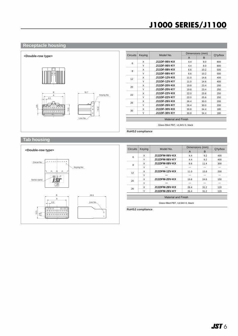
Material and Finish
Glass-filled PBT, UL94V-0, black
6
8
12
20
22
26
30
4.4
4.4
6.6
6.6
11.0
11.0
19.8
19.8
22.0
22.0
26.4
26.4
30.8
30.8
8.0
8.0
10.2
10.2
14.6
14.6
23.4
23.4
25.6
25.6
30.0
30.0
34.4
34.4
800
800
500
500
400
400
250
250
250
250
200
200
180
180
X
Y
X
Y
X
Y
X
Y
X
Y
X
Y
X
Y
J11DF-06V-KXJ11DF-06V-KYJ11DF-08V-KXJ11DF-08V-KYJ11DF-12V-KXJ11DF-12V-KYJ11DF-20V-KXJ11DF-20V-KYJ11DF-22V-KXJ11DF-22V-KYJ11DF-26V-KXJ11DF-26V-KYJ11DF-30V-KXJ11DF-30V-KY
Dimensions (mm)Circuits Keying Model No.
A BQ’ty/box
Material and Finish
Glass-filled PBT, UL94V-0, black
6
8
12
20
26
4.4
4.4
6.6
—
11.0
—
19.8
—
26.4
26.4
9.2
9.2
11.4
—
15.8
—
24.6
—
31.2
31.2
400
400
300
—
200
—
150
—
120
120
X
Y
X
Y
X
Y
X
Y
X
Y
J11DFM-06V-KX�J11DFM-06V-KY�J11DFM-08V-KX�
—�
J11DFM-12V-KX�—�
J11DFM-20V-KX�—�
J11DFM-26V-KX�J11DFM-26V-KY
Dimensions (mm)Circuits Keying Model No.
A BQ’ty/box
Receptacle housing
Tab housing
RoHS2 compliance
RoHS2 compliance
J1000 SERIES/J1100

77
Keying No.
Line No.
Connector outlineConnector outline
Series name
Circuit No.
�PC board layout (Reference)(6-circuit)
(viewed from component side)
�PC board layout (Reference)(Other than 6-circuit)
(viewed from component side)
A±0.05(2.4) A±0.05(2.4)
(B)
1±0.1
(12.3)
2±0.05
(2.5)
2.7±0.05
3.9±0.05
(B)
2.2±0.05(2.5)
2.7±0.05
3.9±0.05
(12.3)
1±0.1
2±0.05C±0.05
2.7
3.9
3.2
3.619.5
12.3
3.9
2.2A
B
C
2.2±0.05φ1±0.05
BA
X
10987654321
φ1±0.05
<Double-row type>
Post: Copper alloy, gold-plated, tin-platedHousing: Glass-filled PBT, UL94V-0, blackReinforcement: Copper alloy, tin-plated
Material and Finish
B
6
8
12
20
22
26
30
X
Y
X
Y
X
Y
X
Y
X
Y
X
Y
X
Y
X
Y
X
Y
X
Y
X
Y
B06B-J11DK-GWXRB06B-J11DK-GWYRB06B-J11DK-TXRB06B-J11DK-TYRB08B-J11DK-GWXRB08B-J11DK-GWYRB08B-J11DK-TXRB08B-J11DK-TYRB12B-J11DK-GWXRB12B-J11DK-GWYRB12B-J11DK-TXRB12B-J11DK-TYRB20B-J11DK-GWXRB20B-J11DK-GWYRB20B-J11DK-TXRB20B-J11DK-TYRB22B-J11DK-GWXRB22B-J11DK-GWYRB26B-J11DK-GWXRB26B-J11DK-GWYRB30B-J11DK-GWXRB30B-J11DK-GWYR
4.4
4.4
6.6
6.6
11.0
11.0
19.8
19.8
22.0
26.4
30.8
9.2
9.2
11.4
11.4
15.8
15.8
24.6
24.6
26.8
31.2
35.6
C
—
—
4.4
4.4
8.8
8.8
17.6
17.6
19.8
24.2
28.6
500
500
400
400
280
280
180
180
160
140
120
ACircuits Plating Keying Model No. Q’ty/
boxDimensions (mm)
Gold (0.2μm)
Tin
Gold (0.2μm)
Tin
Gold (0.2μm)
Tin
Gold (0.2μm)
Tin
Gold (0.2μm)
Gold (0.2μm)
Gold (0.2μm)
Post: Copper alloy, gold-plated, tin-platedHousing: Glass-filled PBT, UL94V-0, blackReinforcement: Copper alloy, tin-plated
Material and Finish
B
6
8
12
20
30
X
Y
X
Y
X
Y
X
Y
X
Y
X
Y
X
Y
X
Y
X
Y
S06B-J11DK-GWXRS06B-J11DK-GWYRS06B-J11DK-TXRS06B-J11DK-TYRS08B-J11DK-GWXRS08B-J11DK-GWYRS08B-J11DK-TXRS08B-J11DK-TYRS12B-J11DK-GWXRS12B-J11DK-GWYRS12B-J11DK-TXRS12B-J11DK-TYRS20B-J11DK-GWXRS20B-J11DK-GWYRS20B-J11DK-TXRS20B-J11DK-TYRS30B-J11DK-GWXR
—
4.4
4.4
6.6
6.6
11.0
11.0
19.8
19.8
30.8
—
9.2
9.2
11.4
11.4
15.8
15.8
24.6
24.6
35.6
—
C
—
—
—
—
8.8
8.8
17.6
17.6
28.6
—
375
375
300
300
225
225
135
135
90
—
ACircuits Plating Keying Model No. Q’ty/
boxDimensions (mm)
Gold (0.2μm)
Tin
Gold (0.2μm)
Tin
Gold (0.2μm)
Tin
Gold (0.2μm)
Tin
Gold (0.2μm)
A±0.05(2.4)
A±0.05(2.4)
8±0.05
2.2±0.05
(0.6)
φ1±0.05
(B)
2.2±0.05
(21.2)1±0.1
2±0.05
(B)
2.2±0.05
(21.2)1±0.1
2±0.05C±0.05
(0.6)
8±0.05
2.2±0.05
3.3
(0.6)
2.28
3.1
21.2
C
13.5
12.3
3.9
2.2
AB
A
B
X
10987654321
φ1±0.05
Keying No.
Line No.
Series name
Circuit No.
�PC board layout (Reference)(Other than 6- & 8-circuit)
(viewed from component side)
�PC board layout (Reference)(6- & 8-circuit)
(viewed from component side)
Connector outline Connector outline
<Double-row type>
Header Top entry type
Header Side entry type
RoHS2 compliance Note: 1. Gold-plated product displays (LF) on a label.
2. Contact JST for 0.76μm gold-plated product.
RoHS2 compliance Note: 1. Gold-plated product displays (LF) on a label.
2. Contact JST for 0.76μm gold-plated product.
J1000 SERIES/J1100
8
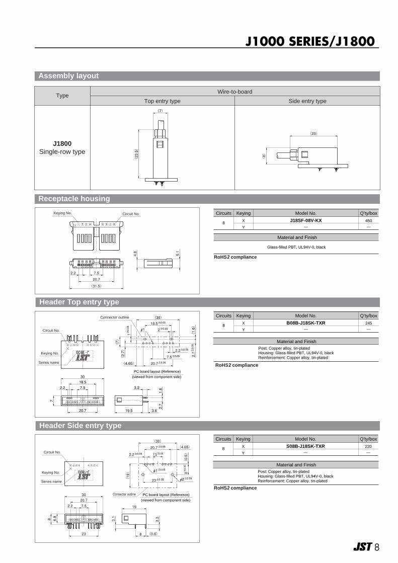
J1000 SERIES/J1800
Top entry type Side entry type
J1800Single-row type
TypeWire-to-board
(23.5)
(7)
(8)
(23)
8 X
Y
J18SF-08V-KX—
450
—
Circuits Keying Model No.
Material and Finish
Glass-filled PBT, UL94V-0, black
Q’ty/box
5.1
4.8
2.2
20.7
7.5
(31.5)
7 85 62 3 4
Keying No. Circuit No.
Receptacle housing
RoHS2 compliance
Assembly layout
Post: Copper alloy, tin-platedHousing: Glass-filled PBT, UL94V-0, blackReinforcement: Copper alloy, tin-plated
Material and Finish
8 X
Y
B08B-J18SK-TXR—
245
—
Circuits Keying Model No. Q’ty/box
20.7
7
18.530
3.2
3.619.5
2.7
1.6
2345678
2.2 7.5
(4.65)
(2.7)
2.2±0.05
φ1
(1.6)
2.7±0.05
20.7±0.057.5±0.05
2±0.0518.5±0.05(30)
(7) 1±0.05
Keying No.
Connector outline
Series name
Circuit No.
�PC board layout (Reference)
(viewed from component side)
Header Top entry type
RoHS2 compliance
Post: Copper alloy, tin-platedHousing: Glass-filled PBT, UL94V-0, blackReinforcement: Copper alloy, tin-plated
Material and Finish
8 X
Y
S08B-J18SK-TXR—
220
—
Circuits Keying Model No. Q’ty/box
2345678
(4.65)
23±0.05
19
30
8 6.8
23
(0.6)
8±0.05
(30)
2.2±0.05
20.7±0.05
7.5±0.05
φ1±0.05
φ2±0.05(19)
20.7
7.52.2
8 (0.6)
3.3
3.1
Keying No.
Connector outline
Series name
Circuit No.
�PC board layout (Reference)
(viewed from component side)
Header Side entry type
RoHS2 compliance
99
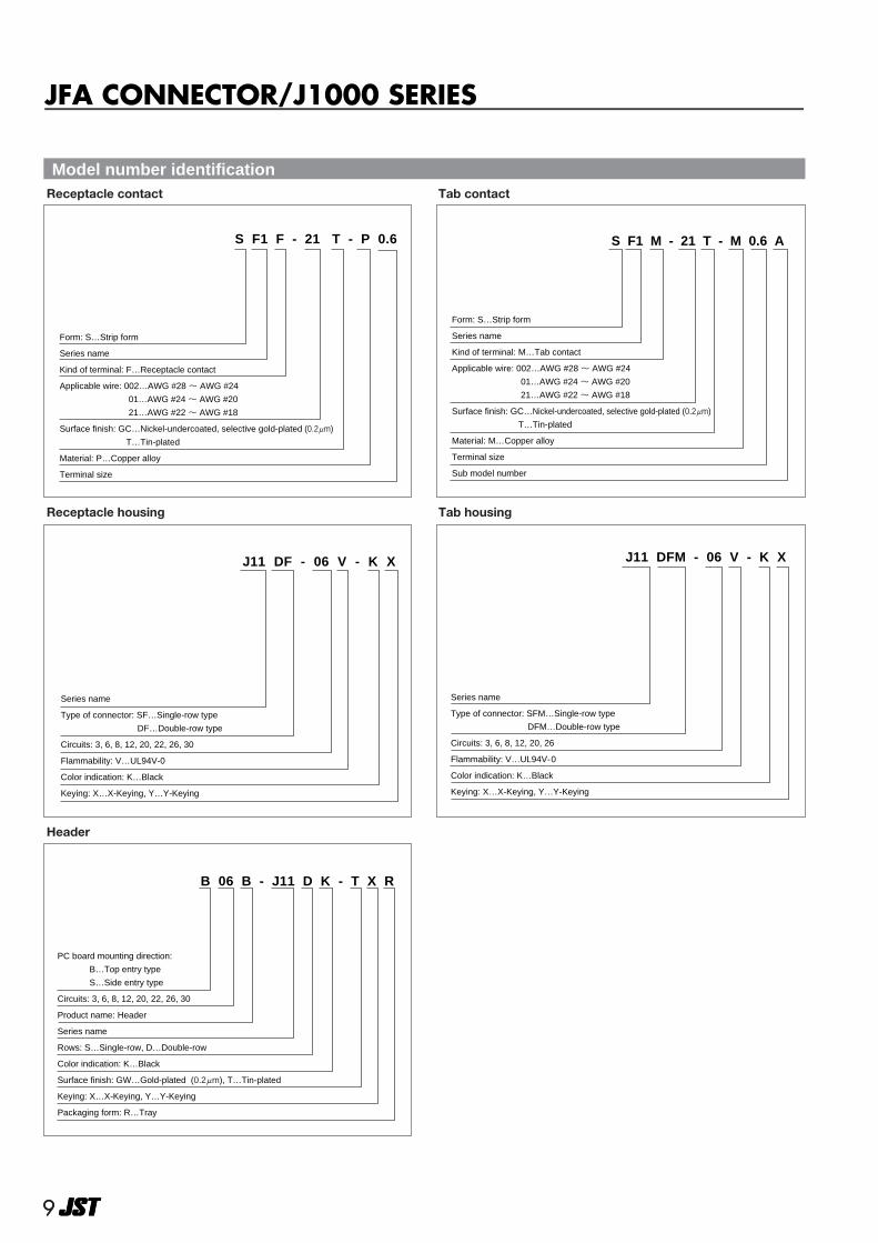
Form: S…Strip form
Series name
Kind of terminal: M…Tab contact
Applicable wire: 002…AWG #28 ~ AWG #24
01…AWG #24 ~ AWG #20
21…AWG #22 ~ AWG #18
Surface finish: GC…Nickel-undercoated, selective gold-plated (0.2μm)
T…Tin-plated
Material: M…Copper alloy
Terminal size
Sub model number
S F1 M - 21 T - M 0.6 A
Tab contact
Form: S…Strip form
Series name
Kind of terminal: F…Receptacle contact
Applicable wire: 002…AWG #28 ~ AWG #24
01…AWG #24 ~ AWG #20
21…AWG #22 ~ AWG #18
Surface finish: GC…Nickel-undercoated, selective gold-plated (0.2μm)
T…Tin-plated
Material: P…Copper alloy
Terminal size
S F1 F - 21 T - P 0.6
Receptacle contact
Series name�
Type of connector: SFM…Single-row type�
� DFM…Double-row type�
Circuits: 3, 6, 8, 12, 20, 26�
Flammability: V…UL94V-0�
Color indication: K…Black�
Keying: X…X-Keying, Y…Y-Keying
J11 DFM - 06 V - K X
Tab housing
Series name
Type of connector: SF…Single-row type
DF…Double-row type
Circuits: 3, 6, 8, 12, 20, 22, 26, 30
Flammability: V…UL94V-0
Color indication: K…Black
Keying: X…X-Keying, Y…Y-Keying
J11 DF - 06 V - K X
Receptacle housing
PC board mounting direction:�
B…Top entry type�
S…Side entry type�
Circuits: 3, 6, 8, 12, 20, 22, 26, 30�
Product name: Header�
Series name�
Rows: S…Single-row, D…Double-row�
Color indication: K…Black�
Surface finish: GW…Gold-plated (0.2μm), T…Tin-plated�
Keying: X…X-Keying, Y…Y-Keying�
Packaging form: R…Tray
B 06 B - J11 D K - T X R
Header
Model number identification
JFA CONNECTOR/J1000 SERIES