JEEP / INTERNATIONAL BODY LIFT KIT … / international body lift kit installation instructions...
10
3651 N Highway 89 • Chino Valley, AZ 86323 (928) 636-7080 • www.p-a-g.net JEEP / INTERNATIONAL BODY LIFT KIT INSTALLATION INSTRUCTIONS 1972-1985 CHEROKEE / WAGONEER / P/U J10, J20 W/ 12 BODY MOUNTS 2” KIT# 922 3” KIT# 923 1975-1982 CHEROKEE / WAGONEER W/ 10 BODY MOUNTS 2” KIT# 902 3” KIT# 903 1972-1982 SCOUT II 2” KIT# 802 3” KIT# 803 WARNING Installation of a Performance Automotive Group body lift kit will change the vehicle’s center of gravity and handling characteristics both on- and off-road. You must drive the vehicle safely! Extreme care must be taken to prevent vehicle rollover or loss of control, which could result in serious injury or death. Avoid sud- den sharp turns or abrupt maneuvers and always make sure all vehicle occupants have their seat belts fas- tened. WARNING Before you install this kit, read and understand all instructions, warnings, cautions, and notes in this instruction sheet and in the vehicle owner’s manual. CAUTION Proper installation of this kit requires knowledge of the factory recommended procedures for removal and installation of original equipment components. We rec- ommend that the factory shop manual and any special tools needed to service your vehicle be on hand during the installation. Installation of this kit without proper knowledge of the factory recommended procedures may affect the performance of these components and the safety of the vehicle. We strongly recommend that a certified mechanic familiar with the installation of sim- ilar components install this kit. WARNING DO NOT combine suspension, body, or other lift devices. Use of vehicle with combined lifts may result in unsafe and/or unexpected handling characteristics. WARNING This kit should only be installed on a vehicle that is in good working condition. Before you install the kit, thor- oughly inspect the vehicle for corrosion or deformation of the sheet metal around the factory body mounts. If the vehicle is suspected to have been in a collision or misused, do not install this kit. Off-road use of your vehicle with this kit installed may increase the stress applied to the factory body mounts. We do not recom- mend that any vehicle with a body lift kit installed be involved in any extreme off-road maneuvers such as jumping. Failure to observe this warning may result in serious personal injury and/or severe damage to your vehicle. WARNING Many states and municipalities have laws restricting bumper heights and vehicle lifts. Consult state and local laws to determine if the changes you intend to make to the vehicle comply with the law. WARNING The installation of larger tires may reduce the effective- ness of the braking system. WARNING Always wear eye protection when operating power tools. WARNING Before you install this kit, block the vehicle tires to pre- vent the vehicle from rolling. WARNING Accidental deployment of the air bag can result in seri- ous personal injury or death. To avoid accidental deployment during installation of the kit, the Supple- mental Restraint System (SRS, or airbag) must remain deactivated. Do not allow anyone near the airbag dur- ing installation. Refer to the factory service manual or owner's manual for the recommended procedure to disable the SRS. After you install the kit, reactivate the SRS before driving the vehicle. NOTE Performance Automotive Group recommends using the Loctite® supplied in the kit on the threads of all kit nuts and bolts unless specified otherwise in these instructions. 1 ‘72-’85 Jeep / International 2”, 3” Body Lift Kit
Transcript of JEEP / INTERNATIONAL BODY LIFT KIT … / international body lift kit installation instructions...

3651 N Highway 89 • Chino Valley, AZ 86323(928) 636-7080 • www.p-a-g.net
JEEP / INTERNATIONALBODY LIFT KITINSTALLATION INSTRUCTIONS1972-1985 CHEROKEE / WAGONEER /
P/U J10, J20 W/ 12 BODY MOUNTS2” KIT# 9223” KIT# 923
1975-1982 CHEROKEE / WAGONEERW/ 10 BODY MOUNTS 2” KIT# 902
3” KIT# 903
1972-1982 SCOUT II 2” KIT# 8023” KIT# 803
WARNING
Installation of a Performance Automotive Group bodylift kit will change the vehicle’s center of gravity andhandling characteristics both on- and off-road. Youmust drive the vehicle safely! Extreme care must betaken to prevent vehicle rollover or loss of control,which could result in serious injury or death. Avoid sud-den sharp turns or abrupt maneuvers and always makesure all vehicle occupants have their seat belts fas-tened.
WARNING
Before you install this kit, read and understand allinstructions, warnings, cautions, and notes in thisinstruction sheet and in the vehicle owner’s manual.
CAUTION
Proper installation of this kit requires knowledge of thefactory recommended procedures for removal andinstallation of original equipment components. We rec-ommend that the factory shop manual and any specialtools needed to service your vehicle be on hand duringthe installation. Installation of this kit without properknowledge of the factory recommended proceduresmay affect the performance of these components andthe safety of the vehicle. We strongly recommend thata certified mechanic familiar with the installation of sim-ilar components install this kit.
WARNING
DO NOT combine suspension, body, or other liftdevices. Use of vehicle with combined lifts may resultin unsafe and/or unexpected handling characteristics.
WARNING
This kit should only be installed on a vehicle that is ingood working condition. Before you install the kit, thor-oughly inspect the vehicle for corrosion or deformationof the sheet metal around the factory body mounts. Ifthe vehicle is suspected to have been in a collision ormisused, do not install this kit. Off-road use of yourvehicle with this kit installed may increase the stressapplied to the factory body mounts. We do not recom-mend that any vehicle with a body lift kit installed beinvolved in any extreme off-road maneuvers such asjumping. Failure to observe this warning may result inserious personal injury and/or severe damage to yourvehicle.
WARNING
Many states and municipalities have laws restrictingbumper heights and vehicle lifts. Consult state andlocal laws to determine if the changes you intend tomake to the vehicle comply with the law.
WARNING
The installation of larger tires may reduce the effective-ness of the braking system.
WARNING
Always wear eye protection when operating powertools.
WARNING
Before you install this kit, block the vehicle tires to pre-vent the vehicle from rolling.
WARNING
Accidental deployment of the air bag can result in seri-ous personal injury or death. To avoid accidentaldeployment during installation of the kit, the Supple-mental Restraint System (SRS, or airbag) must remaindeactivated. Do not allow anyone near the airbag dur-ing installation. Refer to the factory service manual orowner's manual for the recommended procedure todisable the SRS. After you install the kit, reactivate theSRS before driving the vehicle.
NOTE
Performance Automotive Group recommends usingthe Loctite® supplied in the kit on the threads of all kitnuts and bolts unless specified otherwise in theseinstructions.
1 ‘72-’85 Jeep / International 2”, 3” Body Lift Kit

2 ‘72-’85 Jeep / International 2”, 3” Body Lift Kit
Before Starting Installation
1. Carefully read all warnings and instructions com-pletely before beginning.
2. Verify all parts have been received in this kit bychecking the parts list at the end of this document.
3. Only install this kit on the vehicle for which it isspecified. If anytime during the installation youencounter something different from what is outlinedin the instructions, call technical support at (928)636-7080.
4. Special tools needed:
a. Die grinder, hacksaw or similar tool capable ofcutting metal.
b. Length of 2 x 4
5. Park vehicle on a clean, dry, flat, level surface andblock tires so vehicle cannot roll in either direction.
Engine Compartment
1. Disconnect both battery cables. Disconnect nega-tive cable first, then positive cable.
2. Airbag Fuse
a. Remove fuse cover.
b. Remove airbag fuse if present.
NOTE
Kit parts are prefaced by the word kit and appear inbold print.
NOTE
If parts are missing from kit, please be prepared to pro-vide the following information:
1. Name of purchase location2. Bar Code on side of box3. Date above bar code4. Date inside box cover5. Inspector # from inside box cover
NOTE
The location of the airbag fuse may vary; check theowner's manual.
Measurements
1. Measure and record distance between cab and bed.
Driver Side ________ Passenger Side ________
Prepare to Install KitFront of Vehicle
1. Remove hardware and front bumper from vehicle.
Engine Compartment
1. Ensure ample slack (approximately height of lift) inall brake lines, wiring harnesses, radiator and A/Choses, window washer hoses, park brake cables,etc. before lifting cab.
2. Slip-joint models: Steering Shaft
a. Strap steering wheel to prevent accidentalmovement.
WARNING
Accidental deployment of the air bag can result in seri-ous personal injury or death. To avoid accidentaldeployment during installation of the lift kit, the Supple-mental Restraint System (SRS, or airbag) must remaindeactivated. Do not allow anyone near the airbag dur-ing installation. Refer to the factory service manual orowner's manual for the recommended procedure todisable the SRS. After kit installation, the SRS must bereactivated before driving the vehicle.
CAUTION
If the following step is not performed, the airbag clock-spring could be damaged. Do not turn the steeringwheel while the steering shaft is disconnected.

3 ‘72-’85 Jeep / International 2”, 3” Body Lift Kit
b. Inspect steering column slip joint. If pins aresecuring outer sections of slip joints, removepins.
3. Remove hardware, fan and fan shroud from vehicle.
Inside of Vehicle
1. Non slip-joint models: Steering column
a. If steering column does not have a slip joint,loosen bolts and steering column clamp fromunderneath dashboard near firewall.
2. Column shift models: Manual transmission
a. Ensure 1st gear is selected on transmission.
b. Disconnect linkage bars from shift bracket onsteering column and transmission bracket.
3. Floor shift models: Manual transmission
a. Ensure 1st gear is selected on transmission
4. Column shift models: Automatic transmission
a. Ensure transmission is set to ‘Park.’
b. Disconnect linkage bar from shift bracket onsteering column.
5. Floor shift models: Manual transmission
a. Ensure transmission is set to ‘Park.’
6. In-cab fuel tank models:
a. If cab mount bolts are located beneath in-cabfuel tank, it may be necessary to remove fueltank to access cab mount bolts.
Underside of Vehicle
1. Floor shift models: Manual transmission
a. Disconnect clutch linkage from pedal rod andclutch housing.
2. Automatic transmission
a. Disconnect linkage bar from transmissionbracket.
4 ‘72-’85 Jeep / International 2”, 3” Body Lift Kit
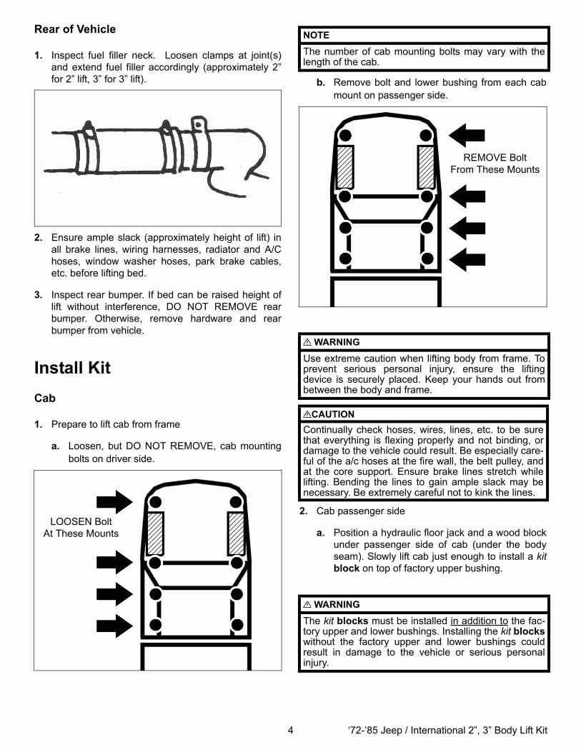
Rear of Vehicle
1. Inspect fuel filler neck. Loosen clamps at joint(s)and extend fuel filler accordingly (approximately 2”for 2” lift, 3” for 3” lift).
2. Ensure ample slack (approximately height of lift) inall brake lines, wiring harnesses, radiator and A/Choses, window washer hoses, park brake cables,etc. before lifting bed.
3. Inspect rear bumper. If bed can be raised height oflift without interference, DO NOT REMOVE rearbumper. Otherwise, remove hardware and rearbumper from vehicle.
Install KitCab
1. Prepare to lift cab from frame
a. Loosen, but DO NOT REMOVE, cab mountingbolts on driver side.
LOOSEN BoltAt These Mounts
b. Remove bolt and lower bushing from each cabmount on passenger side.
2. Cab passenger side
a. Position a hydraulic floor jack and a wood blockunder passenger side of cab (under the bodyseam). Slowly lift cab just enough to install a kitblock on top of factory upper bushing.
NOTE
The number of cab mounting bolts may vary with thelength of the cab.
WARNING
Use extreme caution when lifting body from frame. Toprevent serious personal injury, ensure the liftingdevice is securely placed. Keep your hands out frombetween the body and frame.
CAUTIONContinually check hoses, wires, lines, etc. to be surethat everything is flexing properly and not binding, ordamage to the vehicle could result. Be especially care-ful of the a/c hoses at the fire wall, the belt pulley, andat the core support. Ensure brake lines stretch whilelifting. Bending the lines to gain ample slack may benecessary. Be extremely careful not to kink the lines.
WARNING
The kit blocks must be installed in addition to the fac-tory upper and lower bushings. Installing the kit blockswithout the factory upper and lower bushings couldresult in damage to the vehicle or serious personalinjury.
REMOVE BoltFrom These Mounts

5 ‘72-’85 Jeep / International 2”, 3” Body Lift Kit
b. Install kit blocks onto upper bushings on eachcab mount.
c. Lower cab onto kit blocks.
d. Install lower bushing and kit bolt on each cabmount. DO NOT TIGHTEN.
3. Cab driver side
a. Repeat previous steps on driver side of cab.
b. Set cab-to-bed spacing according to previousmeasurement.
c. Remove each kit bolt, one at a time, and apply asmall amount of kit Loctite® onto threads.Install kit bolt, kit washer, and lower bushing.TIGHTEN kit bolt to 55 ft. lbs.
Bed
1. Prepare to lift bed from frame
a. Loosen, but DO NOT REMOVE, bed mountingbolts on driver side.
LOOSEN BoltAt These Mounts
2. Remove bolt from each bed mount on passengerside.
3. Bed passenger side
a. Using a hydraulic floor jack and a wood block,slowly lift bed just enough to install kit block ontop of frame mounts.
NOTE
The number of bed mounting bolts may vary with thelength of the bed.
WARNING
Use extreme caution when lifting the bed from theframe. To prevent serious personal injury, ensure thelifting device is securely placed. Keep your hands outfrom between the bed and frame.
CAUTION
To prevent damage to the vehicle while lifting the bed,continually check hoses, wires, brake lines, etc. toensure everything is flexing properly and not binding.Ensure clearance between bed and cab is maintained.
REMOVE BoltFrom These Mounts

6 ‘72-’85 Jeep / International 2”, 3” Body Lift Kit
b. Install kit blocks on frame mounts.
c. Lower bed onto kit blocks.
d. Install kit bolts and kit washers onto each bedmount. DO NOT TIGHTEN.
e. Repeat previous steps on driver side of bed.
f. Set bed-to-cab spacing according to previousmeasurement.
g. Remove each kit bolt, one at a time, and apply asmall amount of kit Loctite® onto threads.Install kit bolt with kit washer. TIGHTEN kit boltto 55 ft. lbs.
Rear of Vehicle
1. Rear bumper
a. Install rear bumper onto vehicle with hardware ifremoved.
2. Fuel filler
a. Inspect fuel filler and ensure proper lengthbetween fuel filler hose and fuel tank.
b. TIGHTEN clamps if loosened.
Underside of Vehicle
1. Automatic & Manual transmissions
a. Mark alignment mark lengthwise along linkage.
WARNING
Use extreme caution when working near the fuel linesand the fuel tank. Clean up spilled fuel immediately. Aspark could cause an explosion or fire resulting in seri-ous personal injury and property damage.
b. Mark cut line perpendicular to alignment mark,near linkage halfway.
c. Cut linkage through cut line.
d. Mark kit extension (linkage) lengthwise to allowlinkage section to properly align.
e. Align linkage sections and kit extension (link-age).
f. Weld linkage sections to kit extension (linkage).
g. Install upper end of linkage onto shifter.
h. Install lower end of linkage onto transmission orbracket.
Inside of Vehicle
1. In-cab fuel tank models:
a. Install in-cab fuel tank into cab if removed.
2. Floor shift models:
a. Test transmission shifter in all gears.
b. If shifter does not engage all gears, bend shiftlever slightly towards driver side.
WARNING
All welding should be performed by a certified welderor welding shop.

7 ‘72-’85 Jeep / International 2”, 3” Body Lift Kit
c. If shifter does not engage all gears after per-forming previous substep, remove hardware,shifter boot and boot bracket from floor.
d. Mark and cut sections from boot bracket.
e. Install boot and boot bracket onto floor withhardware.
f. Test transmission shifter in all gears.
3. Non slip-joint models: Steering shaft
a. Adjust steering column beneath dashboard bypulling steering column toward firewall andTIGHTEN loosened hardware.
b. Test steering by turn wheel from left to right sev-eral times.
c. If bind occurs, loosen steering column bolts andclamp. Cut or clearance floor around steeringcolumn to allow steering wheel to assume amore natural position.
d. Drill new holes, if necessary, and install steeringcolumn with clamp, bolts and kit washers, tospace steering column downward approximately1/4”.
Engine Compartment
1. Slip-joint models: Steering shaft
a. Install pins into slip joint if possible.
2. 1979 and older models: Radiator
a. Position 2 x 4 across frame rails beneath radia-tor.
b. Remove hardware and lower radiator onto 2 x 4.
c. Measure 2” (or 3” for 3” lift) below original radia-tor mounting holes in core support and marknew holes.
d. Drill new holes through core support at markedpositions.
e. Install radiator onto new holes in core supportwith hardware.
f. Remove 2 x 4 and install fan and fan shroudonto vehicle with hardware.
3. 1980 and newer models: Radiator
a. Mark horizontal cut line halfway up on fanshroud.
NOTE
Some core supports do not have enough material toallow new holes drilled 2” (or 3” for 3” lift) below originalradiator position. Use kit brackets (radiator) to lowerradiator.
NOTE
These vehicles have a structural member beneathradiator preventing radiator to be lowered. Fan willblow off-center, but will not affect engine performanceor cooling.
8 ‘72-’85 Jeep / International 2”, 3” Body Lift Kit
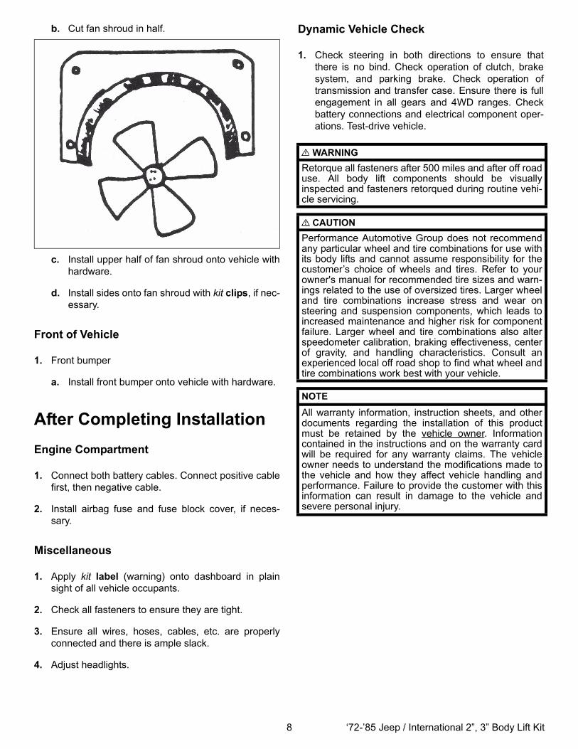
b. Cut fan shroud in half.
c. Install upper half of fan shroud onto vehicle withhardware.
d. Install sides onto fan shroud with kit clips, if nec-essary.
Front of Vehicle
1. Front bumper
a. Install front bumper onto vehicle with hardware.
After Completing InstallationEngine Compartment
1. Connect both battery cables. Connect positive cablefirst, then negative cable.
2. Install airbag fuse and fuse block cover, if neces-sary.
Miscellaneous
1. Apply kit label (warning) onto dashboard in plainsight of all vehicle occupants.
2. Check all fasteners to ensure they are tight.
3. Ensure all wires, hoses, cables, etc. are properlyconnected and there is ample slack.
4. Adjust headlights.
Dynamic Vehicle Check
1. Check steering in both directions to ensure thatthere is no bind. Check operation of clutch, brakesystem, and parking brake. Check operation oftransmission and transfer case. Ensure there is fullengagement in all gears and 4WD ranges. Checkbattery connections and electrical component oper-ations. Test-drive vehicle.
WARNINGRetorque all fasteners after 500 miles and after off roaduse. All body lift components should be visuallyinspected and fasteners retorqued during routine vehi-cle servicing.
CAUTIONPerformance Automotive Group does not recommendany particular wheel and tire combinations for use withits body lifts and cannot assume responsibility for thecustomer’s choice of wheels and tires. Refer to yourowner's manual for recommended tire sizes and warn-ings related to the use of oversized tires. Larger wheeland tire combinations increase stress and wear onsteering and suspension components, which leads toincreased maintenance and higher risk for componentfailure. Larger wheel and tire combinations also alterspeedometer calibration, braking effectiveness, centerof gravity, and handling characteristics. Consult anexperienced local off road shop to find what wheel andtire combinations work best with your vehicle.
NOTE
All warranty information, instruction sheets, and otherdocuments regarding the installation of this productmust be retained by the vehicle owner. Informationcontained in the instructions and on the warranty cardwill be required for any warranty claims. The vehicleowner needs to understand the modifications made tothe vehicle and how they affect vehicle handling andperformance. Failure to provide the customer with thisinformation can result in damage to the vehicle andsevere personal injury.

9 ‘72-’85 Jeep / International 2”, 3” Body Lift Kit
Kit Parts ListKit# 922, 923
Qty. Description14 Block1 Label (logo)1 Label (warning)1 Loctite® (6ml bottle)
1 BP922 (Hardware bag, 2” kit)6 Bolt (7/16”-14 x 4-1/2”)4 Bolt (7/16”-14 x 5-1/2”)2 Bolt (7/16”-14 x 8”)2 Bolt (1/2”-13 x 4”)1 Extension (linkage, 3/8” x 2”)12 Nut (7/16”-14 Nylock)2 Nut (1/2”-13 Nylock)24 Washer (7/16” USS)4 Washer (1/2” USS)
1 BP923 (Hardware bag, 3” kit)6 Bolt (7/16”-14 x 5-1/2”)4 Bolt (7/16”-14 x 6-1/2”)2 Bolt (7/16”-14 x 9”)2 Bolt (1/2”-13 x 5”)1 Extension (linkage, 3/8” x 3”)12 Nut (7/16”-14 Nylock)2 Nut (1/2”-13 Nylock)24 Washer (7/16” USS)4 Washer (1/2” USS)
Kit# 902, 903
Qty. Description10 Block1 Label (logo)1 Label (warning)1 Loctite® (6ml bottle)
1 BP902 (Hardware bag, 2” kit)8 Bolt (7/16”-14 x 5”)2 Bolt (1/2”-13 x 5-1/2”)1 Extension (linkage, 3/8” x 2”)8 Nut (7/16”-14 Nylock)2 Nut (1/2”-13 Nylock)8 Washer (7/16” USS)2 Washer (1/2” USS)
1 BP903 (Hardware bag, 3” kit)8 Bolt (7/16”-14 x 6”)2 Bolt (1/2”-13 x 6-1/2”)1 Extension (linkage, 3/8” x 3”)8 Nut (7/16”-14 Nylock)2 Nut (1/2”-13 Nylock)8 Washer (7/16” USS)2 Washer (1/2” USS)

10 ‘72-’85 Jeep / International 2”, 3” Body Lift Kit
Kit# 802, 803
Qty. Description8 Block1 Label (logo)1 Label (warning)1 Loctite® (6ml bottle)
1 BP802 (Hardware bag, 2” kit)4 Bolt (7/16”-14 x 5-1/2”)2 Bolt (7/16”-14 x 6”)2 Bolt (1/2”-13 x 6-1/2”)3 Extension (linkage, 3/8” x 2”)6 Nut (7/16”-14 Nylock)2 Nut (1/2”-13 Nylock)8 Washer (3/8” USS)12 Washer (7/16” USS)4 Washer (1/2” USS)
1 BP803 (Hardware bag, 3” kit)4 Bolt (7/16”-14 x 6-1/2”)2 Bolt (7/16”-14 x 7”)2 Bolt (1/2”-13 x 7-1/2”)3 Extension (linkage, 3/8” x 3”)6 Nut (7/16”-14 Nylock)2 Nut (1/2”-13 Nylock)8 Washer (3/8” USS)12 Washer (7/16” USS)4 Washer (1/2” USS)
Copyright 09/06Performance Automotive Group
www.p-a-g.net