Jean-Michel Charmet, Rani Hanna and Sami Zellagui,
7
Transcript of Jean-Michel Charmet, Rani Hanna and Sami Zellagui,

Jean-Michel Charmet, Rani Hanna and Sami Zellagui,
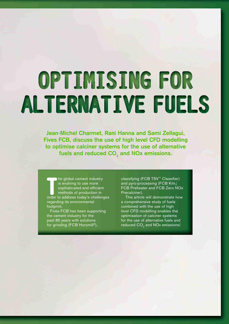
Fives FCB, discuss the use of high level CFD modelling
to optimise calciner systems for the use of alternative
fuels and reduced CO2 and NOx emissions.
The global cement industry is evolving to use more sophisticated and efficient methods of production in
order to address today’s challenges regarding its environmental footprint.
Fives FCB has been supporting the cement industry for the past 85 years with solutions for grinding (FCB Horomill®),
classifying (FCB TSV™ Classifier) and pyro-processing (FCB Kiln, FCB Preheater and FCB Zero NOx Precalciner).
This article will demonstrate how a comprehensive study of fuels combined with the use of high level CFD modelling enables the optimisation of calciner systems for the use of alternative fuels and reduced CO
2 and NOx emissions.
It is now well known that due to both the economic and environmental global situation, the cement industry will have to address tremendous challenges in order to reduce the energy and CO
2 intensity of
production, as well as pollutant emissions. The use of alternative fuels (AF) is one way in which the cement industry can reduce the impact of clinker production on the environment, thus resulting in lower CO
2 and
NOx emissions.Nonetheless, due to the broad range of materials,
geometries, and chemical compositions from biomass to various types of industrial or municipal wastes, a thorough analysis of alternative fuels is necessary in order to evaluate their burning ability parameters and their impact on the clinkerisation process. Fives FCB proposes specific testing procedures to do so, which will be discussed in this article.
In addition, the company has developed a new, high-level, numerical model of the calcination process. This numerical work enables Fives FCB to optimise and adapt the calciner system to special configurations and project constraints related to new plants or revamping projects and specific fuels with guarantees on low NOx emissions. The main principles of the modelling and application examples will also be explored within the article.
Finally, the company’s latest development for the use of coarse 3D alternative fuels in calcining system, will be presented.
Characterisation of alternative fuelsDue to their nature (wide range and heterogeneity), the standard laboratory analyses such as thermogravimetry and chemical analyses may not be relevant to alternative fuels. For this reason, Fives FCB has developed a set of tests in order to evaluate the main parameters governing their combustion:
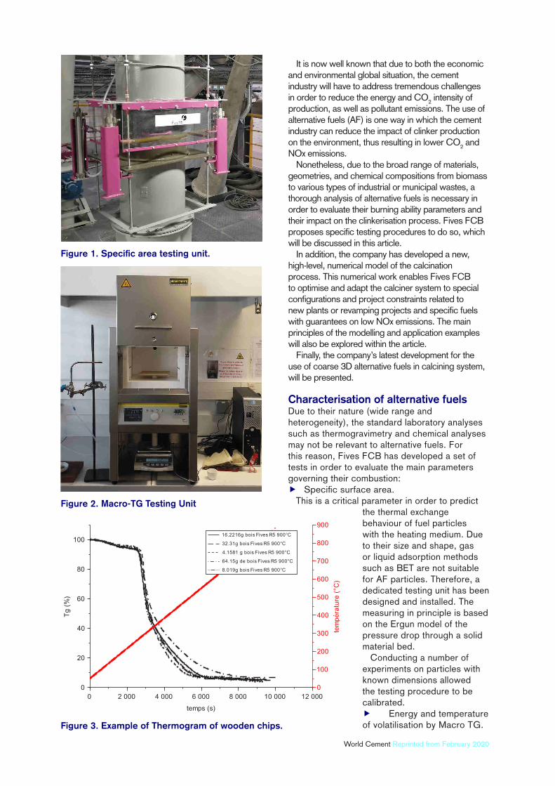
Specific surface area.This is a critical parameter in order to predict
the thermal exchange behaviour of fuel particles with the heating medium. Due to their size and shape, gas or liquid adsorption methods such as BET are not suitable for AF particles. Therefore, a dedicated testing unit has been designed and installed. The measuring in principle is based on the Ergun model of the pressure drop through a solid material bed.
Conducting a number of experiments on particles with known dimensions allowed the testing procedure to be calibrated.
Energy and temperature of volatilisation by Macro TG.
Figure 1. Specific area testing unit.
Figure 2. Macro-TG Testing Unit
Figure 3. Example of Thermogram of wooden chips.
World Cement Reprinted from February 2020
Due to the lack of representativeness, thermo-gravimetric analysis measured on samples of a few mg is not useful for AF. Thermo-grams realised on sample weighing several dozen grams, can be used to characterise several whole particles of AF.
This test determines accurately and, with a good reproducibility, the temperature of volatilisation and ignition of any mix of fuel particles, which can be of various chemical compositions.
Char combustion time in suspension.Once again, to cope with the size of particles,
a special testing unit is necessary in order to determine the required time for char combustion.
The testing cell is able to receive coarse alternative fuels up to 200 mm. A gas flow with controlled temperature and oxygen content is injected and the combustion kinetics of the fuel samples are recorded from the combustion gases composition and a video camera.
A broad range of fuels have been tested with in-house experimental tools in order to build a database which is used for new projects and modelling purposes.
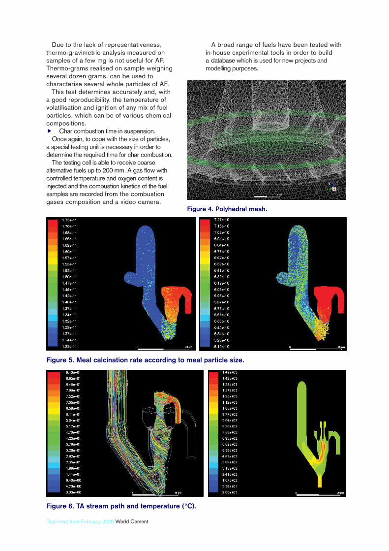
Figure 4. Polyhedral mesh.
Figure 5. Meal calcination rate according to meal particle size.
Figure 6. TA stream path and temperature (°C).
Reprinted from February 2020 World Cement
Furthermore, tests can be conducted to characterise any fuel samples during the early stage of the design process of a new industrial plant, in addition to the standard chemical analyses of the fuels.
CFD simulation of calciner systems
The modelling of the calcination process occurring in a clinker pyro-process is especially complex, as the combustion of the fuels, the chemical reactions of the raw meal, and fluid dynamics are intimately interacting with each other. This is the main reason why results of CFD predictions for cement plants are often perceived as inaccurate.
Fives FCB thus decided to build a new modelling concept, mainly based on experiences and measurements from laboratory and industrial plants. Its model is based on ANSYS Fluent, a powerful CFD software which has been enhanced by user defined functions (UDF) in order to define the interactions within the calcination process more accurately.
Those functions can be dynamically loaded with the ANSYS Fluent solver to improve its standard functionality (customise the boundary conditions, improve an existing model or integrate a new model, etc.).
The UDFs have been defined based on Fives FCB’s experimental results of laboratory calcination tests, realised on various types of limestone and AFs. They allow for the accurate description of the heat and mass transfer related to the particles and calcination reaction.
Model data summary
Fluid dynamics: model k- realisable. Particles: (dpm) discrete phase model. Particle size distribution: raw meal and fuels. Combustion: models from fluent + UDFs for
alternative fuels. Meal Calcination: in-house model using
UDFs. NOx: thermal, prompt and fuel NOx models
from fluent.In addition, due to the complexity of the models and the number of particles (materials + fuels), the grid meshing of the geometry has to be optimised in order to match the computer calculation capacities (Figure 4).
This new model has been used for the simulation of various types of calciner (hot-spot or inline) with any type of fuels (coal/petcoke, natural gas and alternative fuels). Onsite measurements in several industrial plants can be seen to validate its accuracy.
Example of an off-line calciner on new projects
The FCB Zero-NOx Preca is a calciner featuring a hot spot chamber which is efficient for the combustion of low reactivity fuel, such as petcoke or coarse shredded AFs. It remains an effective solution where a significant level of fuel is used in the calciner fuel mix.
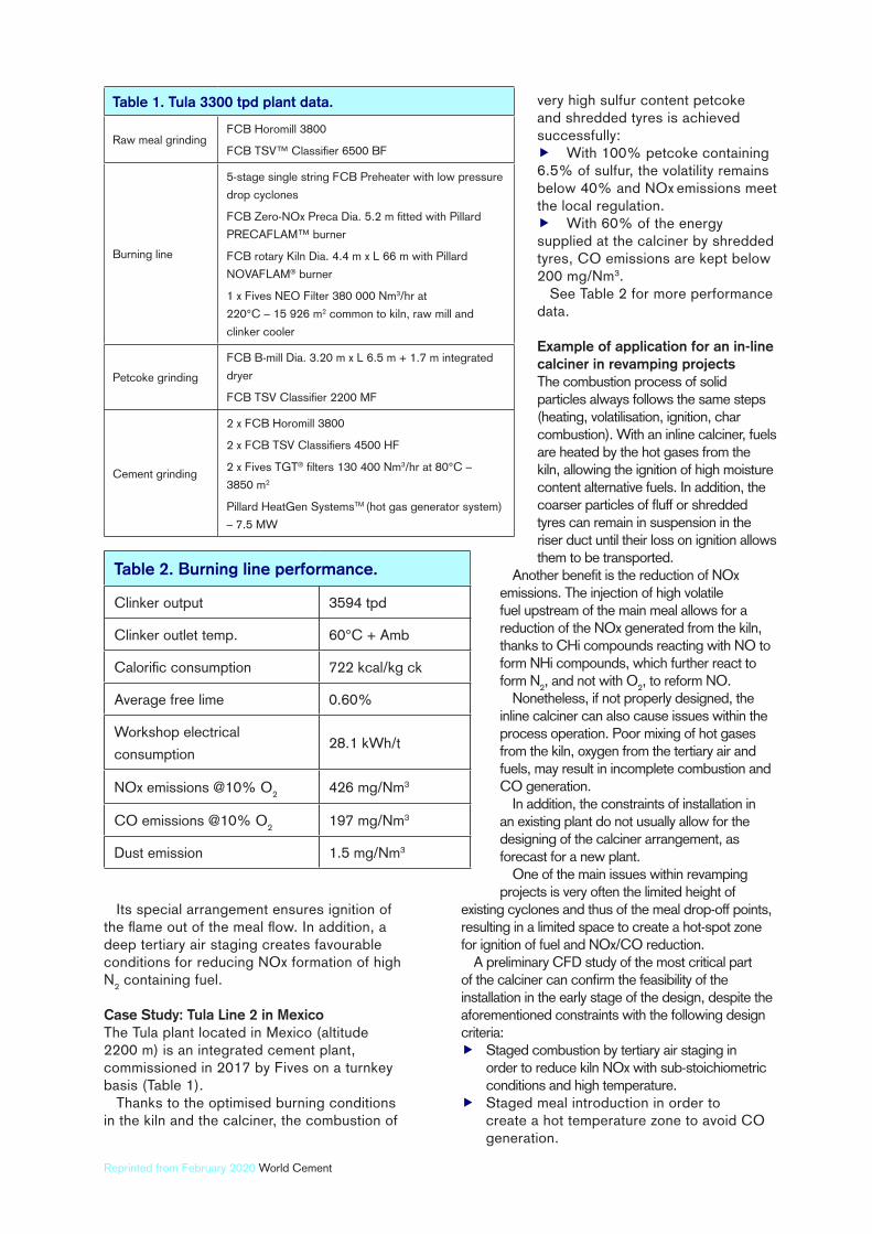
Figure 8. First arrangement (left): high segregation and very high temperature near the wall. Second
arrangement (middle): meal/air and fuels injection showing improvement. Third arrangement
(right): drastically improves mixing and reduces temperature peaks.
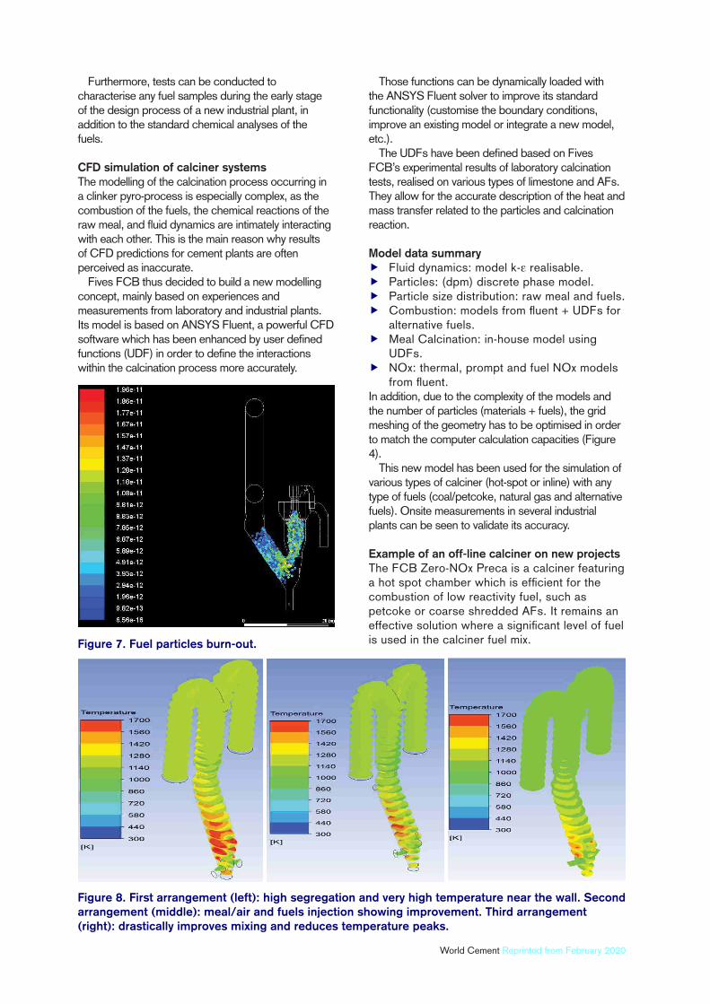
Figure 7. Fuel particles burn-out.
World Cement Reprinted from February 2020
Its special arrangement ensures ignition of the flame out of the meal flow. In addition, a deep tertiary air staging creates favourable conditions for reducing NOx formation of high N
2 containing fuel.
Case Study: Tula Line 2 in Mexico
The Tula plant located in Mexico (altitude 2200 m) is an integrated cement plant, commissioned in 2017 by Fives on a turnkey basis (Table 1).
Thanks to the optimised burning conditions in the kiln and the calciner, the combustion of
very high sulfur content petcoke and shredded tyres is achieved successfully:
With 100% petcoke containing 6.5% of sulfur, the volatility remains below 40% and NOx
emissions meet
the local regulation. With 60% of the energy
supplied at the calciner by shredded tyres, CO emissions are kept below 200 mg/Nm3.
See Table 2 for more performance data.
Example of application for an in-line
calciner in revamping projects
The combustion process of solid particles always follows the same steps (heating, volatilisation, ignition, char combustion). With an inline calciner, fuels are heated by the hot gases from the kiln, allowing the ignition of high moisture content alternative fuels. In addition, the coarser particles of fluff or shredded tyres can remain in suspension in the riser duct until their loss on ignition allows them to be transported.
Another benefit is the reduction of NOx
emissions. The injection of high volatile fuel upstream of the main meal allows for a reduction of the NOx generated from the kiln, thanks to CHi compounds reacting with NO to form NHi compounds, which further react to form N
2, and not with O
2, to reform NO.
Nonetheless, if not properly designed, the inline calciner can also cause issues within the process operation. Poor mixing of hot gases from the kiln, oxygen from the tertiary air and fuels, may result in incomplete combustion and CO generation.
In addition, the constraints of installation in an existing plant do not usually allow for the designing of the calciner arrangement, as forecast for a new plant.
One of the main issues within revamping projects is very often the limited height of
existing cyclones and thus of the meal drop-off points, resulting in a limited space to create a hot-spot zone for ignition of fuel and NOx/CO reduction.
A preliminary CFD study of the most critical part of the calciner can confirm the feasibility of the installation in the early stage of the design, despite the aforementioned constraints with the following design criteria:
Staged combustion by tertiary air staging in order to reduce kiln NOx with sub-stoichiometric conditions and high temperature.
Staged meal introduction in order to create a hot temperature zone to avoid CO generation.
Table 1. Tula 3300 tpd plant data.
Raw meal grindingFCB Horomill 3800
FCB TSV™ Classifier 6500 BF
Burning line
5-stage single string FCB Preheater with low pressure
drop cyclones
FCB Zero-NOx Preca Dia. 5.2 m fitted with Pillard
PRECAFLAM™ burner
FCB rotary Kiln Dia. 4.4 m x L 66 m with Pillard
NOVAFLAM® burner
1 x Fives NEO Filter 380 000 Nm3/hr at
220°C – 15 926 m2 common to kiln, raw mill and
clinker cooler
Petcoke grinding
FCB B-mill Dia. 3.20 m x L 6.5 m + 1.7 m integrated
dryer
FCB TSV Classifier 2200 MF
Cement grinding
2 x FCB Horomill 3800
2 x FCB TSV Classifiers 4500 HF
2 x Fives TGT® filters 130 400 Nm3/hr at 80°C –
3850 m2
Pillard HeatGen SystemsTM (hot gas generator system)
– 7.5 MW
Table 2. Burning line performance.
Clinker output 3594 tpd
Clinker outlet temp. 60°C + Amb
Calorific consumption 722 kcal/kg ck
Average free lime 0.60%
Workshop electrical
consumption28.1 kWh/t
NOx emissions @10% O2
426 mg/Nm3
CO emissions @10% O2
197 mg/Nm3
Dust emission 1.5 mg/Nm3
Reprinted from February 2020 World Cement

Customised venturi to avoid AF dropping to the kiln inlet.
Optimised micro mixing of oxygen and fuels with respect to combustion and heat transfer to the meal.
Up to 100% substitution rate of alternative fuels.
Target NOx emissions of 200 mg/Nm3
@10% O2..
As shown in Figure 8, an optimised arrangement of the geometry and of the various injections (air, meal, fuels, etc.) allows the design criteria to be met.
Using coarse 3D materials as alternative fuels
in the calciner
For very coarse particles (up to 500 mm in the three dimensions) such as timber or waste materials, Fives FCB has developed a new concept with the FCB Preca-Max TM.
A rotary calciner is fitted in the burning line as the first part of an inline calciner. As inline, it allows the ignition of high-moisture content wastes. The residence time (adjustable from 10 to 30 min), is sufficient to ensure the complete char combustion of
large particles.
As coarse particles are highly variable, a secondary fuel with accurate dosing (such as fluff materials) is injected downstream of the chamber to ensure a fine calcination temperature control.
ConclusionThe widespread use of alternative fuels and raw materials constitutes an important element in reducing the environmental footprint of cement production.
Due to the wide range of materials potentially used in the cement production, customised solutions must be applied according to each plant’s constraints and fuel availability.
The use of state-of-the-art CFD simulation, if properly customised thanks to extensive and relevant experimental data, is a powerful tool which can be helpful to rapidly assess the feasibility of any upgrading projects of a cement plant and to optimise the design for maximising the use of alternative fuels, without harmfully impacting upon the process.
References1. ZVENHOVEN, R., & KILPINEN, P., ‘Control
of pollutants in flue gases and fuel gases’, 2004, –
ISBN 951-22-5527-8.
2. GUIMARD, Y., & CHARMET, J.M., –
World Patent # WO 2019/115967.
About the authorsJean-Michel Charmet is a Chemical Engineer, specialising in High Temperature Process Engineering. He has been working as a Pyroprocess team leader with Fives FCB since 2015, after 19 years in development and design of thermal process equipment for various industries (aerospace, automotive and building materials.)
Rani Hanna is a Doctor of Engineering in Energy and Process from Mines ParisTech. He joined Fives FCB research centre (CRCM) as a R&D and process engineer in 2017, and works mainly on the development and improvement of equipment for the cement and minerals industry.
Sami Zellagui is a PhD-engineer in Process and Chemical Engineering. He completed his thesis at Université de Haute-Alsace, studying solid fuels combustion in a drop tube furnace. He joined Fives FCB research centre (CRCM) as a R&D engineer in 2017, and works on the subjects of pyroprocessing and alternative fuels.
Figure 10. FCB Preheater and calciner with AF feeding.
Figure 9. FCB Preca-MaxTM.