
JBRAKE CONTROL SYSTEM 1. Generalmanualespurdy.cisdigital.com/Lexus/RX400h/rm03g0u/... · Vehicle...
48
CHASSIS — BRAKE CH-40 J BRAKE CONTROL SYSTEM 1. General D A brake management function, VDIM (Vehicle Dynamics Integrated Management), which delivers comprehensive vehicle movement control, is new on the RX400h. D An ECB (Electronically Controlled Brake) system is new on the RX400h. D The brake control system of the RX400h is controlled by the skid control ECU. This ECU maintains communication with the EPS ECU and the THS ECU via the CAN (Controller Area Network). 2. VDIM (Vehicle Dynamics Integrated Management) General D The VDIM manages all functions, such as the ABS with EBD, the Brake Assist, the TRAC, and the VSC. And is operated by the ECB system, which regulates brake fluid pressure. In addition, the regenerative brake cooperative control and power steering cooperative control functions are also available, thus allowing the VDIM to perform the comprehensive management. D Conventional brake control systems begin to control either the braking or motive force in order to stabilize the vehicle motion, when it becomes unstable due to loss of tire traction. In contrast, in order to maintain stable vehicle control, the VDIM commences controlling the brake, hybrid and steering systems in accordance with changes in balance before the vehicle becomes unstable. As a result, maintenance smooth vehicle control is achieved. D Conventional brake control systems manage all related functions, such as the ABS with EBD, the Brake Assist, the TRAC and the VSC, independently, according to the vehicle dynamics. In contrast, the VDIM provides smooth control by seamlessly integrating all brake control related functions. " Conceptual Diagram of Control Management A 277CH143 277CH144 Cornering VSC Braking ABS with EBD Driving TRAC Cornering VSC Vehicle Control Areas Each function has its own control area and is operated independently Cornering Braking Driving Cornering Vehicle Control Areas All functions are operated seamlessly in unison with each other Vehicle Vehicle Conventional VDIM
Transcript of JBRAKE CONTROL SYSTEM 1. Generalmanualespurdy.cisdigital.com/Lexus/RX400h/rm03g0u/... · Vehicle...

NCF277U
CHASSIS—BRAKECH-40
JBRAKE CONTROL SYSTEM
1. General
D A brake management function, VDIM (Vehicle Dynamics Integrated Management), which deliverscomprehensive vehicle movement control, is new on the RX400h.
D An ECB (Electronically Controlled Brake) system is new on the RX400h.D The brake control system of the RX400h is controlled by the skid control ECU. This ECU maintainscommunication with the EPS ECU and the THS ECU via the CAN (Controller Area Network).
2. VDIM (Vehicle Dynamics Integrated Management)
General
D TheVDIMmanages all functions, such as theABSwithEBD, theBrakeAssist, the TRAC,and theVSC.And is operated by the ECB system, which regulates brake fluid pressure. In addition, the regenerativebrake cooperative control and power steering cooperative control functions are also available, thusallowing the VDIM to perform the comprehensive management.
D Conventional brake control systems begin to control either the braking or motive force in order tostabilize the vehicle motion, when it becomes unstable due to loss of tire traction. In contrast, in orderto maintain stable vehicle control, the VDIM commences controlling the brake, hybrid and steeringsystems in accordance with changes in balance before the vehicle becomes unstable. As a result,maintenance smooth vehicle control is achieved.
D Conventional brake control systems manage all related functions, such as the ABSwith EBD, the BrakeAssist, theTRACand theVSC, independently, according to the vehicle dynamics. In contrast, theVDIMprovides smooth control by seamlessly integrating all brake control related functions.
" Conceptual Diagram of Control ManagementA
277CH143
277CH144
Cornering VSC
Braking ABS with EBD
Driving TRAC
Cornering VSC
Vehicle Control Areas Each function has its own controlarea and is operated independently
Cornering
Braking
Driving
Cornering
Vehicle Control Areas All functions are operated seamlesslyin unison with each other
Vehicle
Vehicle
Conventional
VDIM

NCF277U
CH
CHASSIS—BRAKE CH-41
" Examples of Control OperationA
The difference in vehicle control during harsh braking situations while cornering, with the VDIM andconventional brake control systems, is as follows:
Conventional
Conventional brake control systems calculate vehicle motion based on signals transmitted by yaw rate anddeceleration sensors, the wheel speed sensors and the steering sensor, and activates VSC systems whenvehicles are determined to be skidding. If the driver brakes suddenly, brake control systems performassisting control to stabilize the vehicle dynamics, by activating the ABS system when a locked wheel isdetected, or by affecting the VSC system when skidding is detected.
277CH146
Vehicle Dynamics
Braking
: VSC or ABSControl Area
Harsh Braking
VDIM
TheVDIMalso calculates vehiclemotion based onsignals from the yawrate anddeceleration sensor,wheelspeed sensors and steering sensor.When the calculations indicate that thevehicle is likely to skid, theVDIMbegins vehicle control with the VSC function. In addition, if the driver brakes suddenly, the VDIM reducesvehicle instability to a minimum and assists in achieving optimum driving stability by seamlesslydelivering a suitable combination of the VSC and ABS functions.
277CH147
Vehicle Dynamics
Braking
: VDIM Control Area
Harsh Braking

NCF277U
CHASSIS—BRAKECH-42
" Control Configuration of VDIMA
277CH145
Target VehicleBehavior Calculation
Vehicle ConditionCalculation
Sensors
Brake System Steering System
Skid Control ECU
Control ValueCalculation
Hybrid System
The brake system of the RX400h has a following function:
BrakeControlSystem
Function Outline
Regenerative BrakeCooperative Control
Controls hydraulic braking in order to recover electricalenergy by utilizing the regenerative brake of the THS-IIsystem as much as possible.
Power Steering CooperativeControl
Effects cooperative control with the EPS ECU in order toprovide steering assist in accordance with the operatingconditions of the vehicle.
� This system electrically detects the operationinformation for the brake pedal and generates anappropriate amount of hydraulic brake.
� Executes the hydraulic control of the brake controlfunctions based on the VDIM.
VSC(Vehicle StabilityControl)
The VSC function helps prevent the vehicle from slippingsideways as a result of strong front wheel skid or strong rearwheel skid during cornering.
VDIM TRAC(Traction Control)
The TRAC function helps prevent the drive wheels fromslipping if the driver presses the accelerator pedalexcessively when starting off or accelerating on a slipperysurface.
ECB
ABS(Anti-lock BrakeSystem)
The ABS helps prevent the wheels from locking when thebrakes are applied firmly or when braking on a slipperysurface.
System
EBD(Electronic Brakeforce Distribution)
The EBD control utilizes ABS, realizing the proper brakeforce distribution between front and rear wheels inaccordance with the driving conditions.In addition, during cornering braking, it also controls thebrake forces of right and leftwheels, helping tomaintain thevehicle behavior.
Brake Assist
The primary purpose of the Brake Assist is to provide anauxiliary brake force to assist the driver who cannotgenerate a large brake force during emergencybraking, thushelping the vehicle’s brake performance.

NCF277U
CH
CHASSIS—BRAKE CH-43
Outline of Regenerative Brake Cooperative Control Function
1) General
D Regenerative brake consists of a resistance force that is generated at the rotational axle in the reversedirection of the rotation of the generator (MG2 and MGR*) that is generating electricity. The greaterthe generated amperage (battery charging amperage), the greater will be the resistance force.
277CH112
Engine MGR*
Brake Force
HVBattery
Inverter
Rotating direction toelectricity generation
Resistance
MG1
MG2
HVBattery
InverterMG1
Engine
MG2
Brake Force
MGR*
Resistance
Rotating direction toelectricity generation
D The front and rear drive axles are joined mechanically by theMG2 andMGR*generators, which drivethe respective axles. The rotationalmovement of the drivewheels driveMG2andMGR*, causing themto operate as generators, and the generative brake forces ofMG2 andMGR*are transmitted to the drivewheels. These forces are controlled by the THS-II system, which controls the generation of electricity.The regenerative brake cooperative control does not rely solely on the braking force of the hydraulicbrake system to supply the brake force required by the driver. Instead, by effecting cooperative controlwith the THS-II system, this control provides a joint braking force provided by the regenerative brakeand the hydraulic brake. As a result, this control minimizes the loss of the kinetic energy associatedwith the normal hydraulic brake, and recovers this energy by converting it into electrical energy.
*: Only on Models with 4WD System

NCF277U
CHASSIS—BRAKECH-44
2) Apportioning of the Brake Force
D The apportioning of the brake force between the hydraulic brake and the regenerative brake varies bythe vehicle speed and time.
D The apportioning of the brake force between the hydraulic brake and the regenerative brake isaccomplished by controlling the hydraulic brake so that the total brake force of the hydraulic brake andthe regenerative brake matches the brake force required by the driver.
D If the regenerative brake becomes inoperative due to a malfunction in the THS-II system, the brakesystem effects control so that the entire brake force required by the driver is suppliedwith the hydraulicbrake system.
" Imagery DrawingA
277CH142
Vehicle Speed
Driver’s Demand
Hydraulic BrakingForce
Battery AcceptanceCapacity
RegenerativeBraking Force
BrakingForce
NCF277U
CH
CHASSIS—BRAKE CH-45
Outline of Power Steering Cooperative Control Function
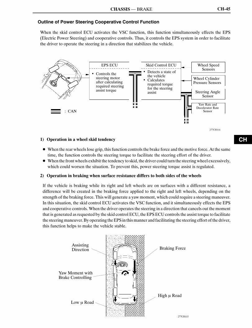
When the skid control ECU activates the VSC function, this function simultaneously effects the EPS(Electric Power Steering) and cooperative controls. Thus, it controls the EPS system in order to facilitatethe driver to operate the steering in a direction that stabilizes the vehicle.
277CH114
: CAN
EPS ECU
Controls thesteering motorafter calculatingrequired steeringassist torque
Skid Control ECU
Detects a state ofthe vehicle
Calculatesrequired torquefor the steeringassist
Wheel SpeedSensors
Wheel CylinderPressure Sensors
Steering AngleSensor
Yaw Rate andDecelerator Rate
Sensor
1) Operation in a wheel skid tendency
D When the rear wheels lose grip, this function controls the brake force and themotive force. At the sametime, the function controls the steering torque to facilitate the steering effort of the driver.
D When the frontwheels exhibit the tendency to skid, the driver could turn the steeringwheel excessively,which could worsen the situation. To prevent this, power steering torque assist is regulated.
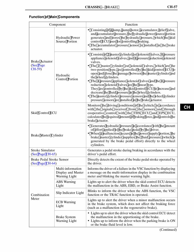
2) Operation in braking when surface resistance differs to both sides of the wheels
If the vehicle is braking while its right and left wheels are on surfaces with a different resistance, adifference will be created in the braking force applied to the right and left wheels, depending on thestrength of the braking force. This will generate a yawmoment, which could require a steeringmaneuver.In this situation, the skid control ECU activates the VSC function, and it simultaneously effects the EPSand cooperative controls.When the driver operates the steering in a direction that cancels out themomentthat is generated as requested by the skid control ECU, the EPSECUcontrols the assist torque to facilitatethe steeringmaneuver.Byoperating theEPS in thismanner and facilitating the steering effort of thedriver,this function helps to make the vehicle stable.
277CH115
AssistingDirection
Yaw Moment withBrake Controlling
Braking Force
Low � Road
High � Road

NCF277U
CHASSIS—BRAKECH-46
3. ECB (Electronically Controlled Brake) System
General
D In this system, the conventional brake booster portion has been discontinued. Instead, it consists of brakeinput, power supply, and hydraulic pressure control portions.
D During normal braking, the fluid pressure generated by the master cylinder does not directly actuate thewheel cylinders, but serves as a hydraulic pressure signal. Instead, the actual control pressure is obtainedby regulating the fluid pressure of the hydraulic power source in the brake actuator, which actuates thewheel cylinders.
D The ECB executes the hydraulic control of the ABS with EBD, brake assist, TRAC, and VSC functionin accordance with information provided by the sensors and ECUs.
D The power source backup unit is used as an auxiliary power source, to supply power to the brake systemin a stable manner.
" Outline of ECB SystemA
277CH111
Brake Pedal StrokeSensor
Master CylinderPressure Sensor
Skid Control ECU Normal Brake, ABS with EBD, BrakeAssist, VSC and TRAC Function
Regenerative Brake CooperativeFunction
Power Steering Cooperative Function
Hydraulic PowerSource Portion Generates hydraulicpower using thepump
Hydraulic Control Portion Hydraulic power isadjusted to the requiredbraking force, anddistributes it to each wheel
Hydraulic Brake Force
: Electrical Signal
: Fluid Pressure
EPS Steering Assist
THS-II Regenerative Brake
RegenerativeBrake Force
Brake Force

NCF277U
CH
CHASSIS—BRAKE
181CH56
CH-47
Outline of EBD Control Function
1) General
Thedistribution of thebrake force,whichwasperformedmechanically in thepast, is nowperformedunderelectrical control of the skid control ECU, which precisely controls the braking force in accordance withthe vehicle’s driving conditions.
2) Front/Rear Wheels Brake Force Distribution
If the brakes are applied while the vehicle is moving straight forward, the transfer of the road reduces theload that is applied to the rear wheels. The skid control ECU determines this condition by way of thesignals from the wheel speed sensors, and the brake actuator regulates the distribution of the brake forceof the rear wheels to optimally control.For example, the amount of the brake force that is applied to the rearwheels during braking varieswhetheror not the vehicle is carrying a load. The amount of the brake force that is applied to the rear wheels alsovaries in accordance with the extent of the deceleration.Thus, the distribution of the brake force to the rear is optimally controlled in order to effectively utilizethe braking force of the rear wheels under these conditions.
" EBD Control ConceptA
182CH56
Ideal Brake ForceDistribution
EBD Control
Without Load in Rear
RearBrakeForce
Ideal Brake Force Distribution
EBD Control
With Load in Rear
RearBrakeForce
Front Brake Force Front Brake Force
Right/Left Wheels Brake Force Distribution (During Cornering Braking)
When the brakes are applied while the vehicle iscornering, the load that applied to the inner wheeldecreases and the outer wheel increases.The skid control ECU determines this condition byway of the signals from the wheel speed sensors,and the brake actuator regulates the brake force inorder to optimally control the distribution of thebrake force to the inner wheel and outer wheel.

NCF277U
CHASSIS—BRAKECH-48
Outline of Brake Assist Function
The brake assist function interprets a quick push of the brake pedal as emergency braking and supplementsthe braking power applied if the driver has not stepped hard enough on the brake pedal. In emergencies,drivers, especially inexperienced ones, often panic and do not apply sufficient pressure on the brake pedal.Based on the signals from the master cylinder pressure sensors and the brake pedal stroke sensor, the skidcontrol ECU calculates the speed and the amount of the brake pedal application and then determines theintention of the driver to make an emergency braking. If the skid control ECU determines that the driverintends emergency braking, the function activates the brake actuator to increase the brake fluid pressure.The brake assist function in combination with ABS helps ensure the vehicle’s brake performance.A key feature of Brake Assist function is that the timing and the degree of braking assistance are designedto ensure that the driver does not discern anything unusual about the braking operation.When the driver intentionally eases up on the brake pedal, the function reduces the amount of assistanceit provides.
255CH131 255CH132
Master CylinderPressure SensorSignal
without Brake Assist Functionwith Brake Assist Function
Skid ControlECU
The fluid pressureis increased by thebrake actuator
Brake PedalStroke SensorSignal
� : There is no difference of the maximum brake performance between the vehicles with and withoutbrake assist function.
170CH18
BrakingForce
Time

NCF277U
CH
CHASSIS—BRAKE CH-49
Outline of TRAC Function
D If the driver presses the accelerator pedal aggressively when starting off or accelerating on a slipperysurface, the drive wheel could slip due to the excessive amount of torque that is generated. Theadjustment of themotive force and the control of the hydraulic brakes of the drive wheels accomplishedby THS-II allow the TRAC function to help minimize the slippage of the drive wheels, and generate thedrive force that is appropriate for the road surface conditions.
D For example, a comparison may be made between two vehicles, one with the TRAC function and theotherwithout. If the driver of each vehicle operates the accelerator pedal in a roughmannerwhile drivingover a surfacewith different surface friction characteristics, the drivewheel on the slippery surface couldslip as illustrated. As a result, the vehicle could become unstable.However, when the vehicle is equipped with the TRAC function, the skid control ECU instantlydetermines the state of the vehicle and operates the brake actuator in order to apply the brake of theslipping drive wheel. Simultaneously, the skid control ECU effects cooperative control with the THSECU, in order to adjust the motive force. Thus, this function can constantly maintain a stable vehicleposture.
" Driving condition on road with different surface friction characteristicsA
277CH113
Slippery Surface
Slippery Surface
Engine and MG2� Motive forceregulation
MGR� Motive ForceRegulation
Brake theslippingdrive-wheel
Brake Actuator
without TRAC Function
with TRAC Function
Skid Control ECU
THS ECU
zThis case applies only to the 4WD model. On the 2WD model,control is effected on the front wheels, which are the drive wheels.

NCF277U
CHASSIS—BRAKE
151CH19
Actual Locus of Travel(Actual Yaw Rate)
Locus of TravelBased on theTarget Yaw Rate
CH-50
Outline of VSC Function
1) General
The followings are two examples that can be considered as circumstances in which the tires exceed theirlateral grip limit.The VSC function is designed to help control the vehicle behavior by controlling the motive force andthe brakes at each wheel when the vehicle is under one of the conditions indicated below.D When the front wheels lose grip in relation to the rear wheels (front wheel skid tendency).D When the rear wheels lose grip in relation to the front wheels (rear wheel skid tendency).
189CH100151CH17
Rear Wheel Skid TendencyFront Wheel Skid Tendency
2) Method for Determining the Vehicle Condition
To determine the condition of the vehicle, sensors detect the steering angle, vehicle speed, vehicle’s yawrate, and the vehicle’s lateral acceleration, which are then calculated by the skid control ECU.
a. Determining Front Wheel Skid
Whether or not the vehicle is in the state of frontwheel skid is determined by the differencebetween the target yaw rate and the vehicle’sactual yaw rate.When the vehicle’s actual yaw rate is smallerthan the yaw rate (a target yaw rate that isdetermined by the vehicle speed and steeringangle) that should be rightfully generated whenthe driver operates the steering wheel, it meansthe vehicle is making a turn at a greater anglethan the locus of travel.Thus, the skid control ECUdetermines that thereis a large tendency to front wheel skid.

NCF277U
CH
CHASSIS—BRAKE
151CH18
Movement of Vehicle
Direction of Travel of the Vehicle’sCenter of Gravity
Slip Angle
189CH101
Braking Force
BrakingForce
Braking Force
Control Moment
Making a Right Turn
204CH15
Braking Force
Control Moment
Making a Right Turn
CH-51
b. Determining Rear Wheel Skid
Whether or not the vehicle is in the state of rearwheel skid is determined by the values of thevehicle’s slip angle and the vehicle’s slip angularvelocity (time-dependent changes in thevehicle’s slip angle). When the vehicle’s slipangle is large, and the slip angular velocity isalso large, the skid control ECU determines thatthe vehicle has a large rear wheel skid tendency.
3) Method for VSC Operation
When the skid control ECU determines that the vehicle exhibits a tendency to front wheel skid or rearwheel skid, it decreases the engine output and applies the brake of a front or rear wheel to control thevehicle’s yaw moment.The basic operation of the VSC is described below. However, the control method differs depending onthe vehicle’s characteristics and driving conditions.
a. Dampening a Front Wheel Skid
When the skid control ECU determines thatthere is a large front wheel skid tendency, itcounteracts in accordance with the extent of thattendency. The skid control ECU controls themotive power output and applies the brakes ofthe front wheel of the outer circle in the turns andrear wheels in order to restrain the front wheelskid tendency.
b. Dampening a Rear Wheel Skid
When the skid control ECU determines thatthere is a large rear wheel skid tendency, itcounteracts in accordance with the extent of thattendency. It applies the brakes of the front wheelof the outer circle of the turn, and generates anoutward moment of inertia in the vehicle, inorder to restrain the rear wheel skid tendency.Along with the reduction in the vehicle speedcaused by the braking force, the excellentvehicle’s stability is ensured.In some cases, the skid control ECU applies thebrake of the rear wheels, as necessary.

NCF277U
CHASSIS — BRAKECH-52
Outline of Brake Control (Operating Dynamic Laser Cruise Control System)
If the distance to the vehicle being driven ahead decreases during a dynamic laser cruise control systemoperation, it might not be possible for the vehicle to attain a sufficient amount of deceleration by restrainingthe engine and motor output controlled by the THS ECU. In this instance, even if the driver is not depressingthe brake pedal, the skid control ECU activates the brake actuator and starts braking, in order to attain thetarget deceleration rate that is constantly calculated and requested by the distance control ECU. As a result,the stoplights illuminate.At the end of braking, the skid control ECU gradually decreases the braking force and ends it in order todecelerate smoothly.If further deceleration is required, the system sounds a warning buzzer to alert the driver to apply the brakes.This warning buzzer is used concurrently with the warning buzzer for the VSC function.For details, see the Dynamic Laser Cruise Control System on page BE-157.
277CH122
THS ECU RestrainsPower Output
� THS ECU RestrainsPower Output
� Braking Operation
BrakingOperation
SoundingBuzzer
Set Vehicle Distance

NCF277U
CH
CHASSIS—BRAKE CH-53
System Diagram
277CH116
Brake PedalStroke Sensor Stop Light Switch
BrakeActuator
Brake StrokeSimulator
Brake Fluid LevelWarning Switch
Battery(12V)
WheelSpeedSensors
Speedometer
Combination Meter
Main Relay 2
Power Source Backup Unit
Parking Brake Switch
Stop Light*
BEAN(Instrument Panel Bus)
Data Link Connector 3
Multi-information Display
ABS Warning Light
Slip Indicator Light
Brake System Warning LightSkid
ControlECU
ECBWarning Light
*: Only for Models with Dynamic Laser Cruise Control System
EPS ECU
Master Warning Light
CAN
VSC Warning Buzzer
Yaw Rate Sensor
Deceleration Rate Sensor
Gateway ECU
Steering Angle Sensor
THS ECU
Stop LightRelay*
Main Relay 1
Pump Motor Relay 2
Pump Motor Relay 1
WheelSpeedSensors

NCF277U
CHASSIS—BRAKECH-54
Construction
The configuration of the brake control system on the RX400h is as shown in the following chart.
277CH117
(Continued)
BRAKE ACTUATOR
MASTER CYLINDER CUTSOLENOID VALVE 1
MASTER CYLINDER CUTSOLENOID VALVE 2
PRESSURE APPLIANCESOLENOID VALVE (FL)
PRESSURE REDUCTIONSOLENOID VALVE (FL)
PRESSURE APPLIANCESOLENOID VALVE (FR)
PRESSURE REDUCTIONSOLENOID VALVE (FR)
PRESSURE APPLIANCESOLENOID VALVE (RL)
PRESSURE REDUCTIONSOLENOID VALVE (RL)
PRESSURE APPLIANCESOLENOID VALVE (RR)
PRESSURE REDUCTIONSOLENOID VALVE (RR)
MASTER CYLINDERPRESSURE SENSOR 1
MASTER CYLINDERPRESSURE SENSOR 2
WHEEL SPEED SENSOR(FL)
WHEEL SPEED SENSOR(FR)
WHEEL SPEED SENSOR(RL)
WHEEL SPEED SENSOR(RR)
PEDAL STROKE SENSOR
STROKE SIMULATORCUT VALVE
MAIN RELAY 1
MAIN RELAY 2
POWER SOURCEBACKUP UNIT
BRAKE FLUID LEVELWARNING SWITCH
STOP LIGHT SWITCH
PARKING BRAKE SWITCH
SMC1
SMC2
RLA
FLA
FLR
FRA
FRR
RLR
RRA
RRR
PMC1
PMC2
FL
FR
RL
RR
SKS1
SCSS
BS1
BS2
FAIL
LBL
STP
PKB
ENA
R2
R1
SKS2SKID
CONTROLECU

NCF277U
CH
CHASSIS—BRAKE CH-55
277CH118
WHEEL CYLINDERPRESSURE SENSOR (FL)
WHEEL CYLINDERPRESSURE SENSOR (FR)
WHEEL CYLINDERPRESSURE SENSOR (RL)
PUMP MOTORRELAY 1
WHEEL CYLINDERPRESSURE SENSOR (RR)
ACCUMULATORPRESSURE SENSOR
PUMP MOTOR
VSC WARNING BUZZER
DATA LINK CONNECTOR 3
STEERING ANGLESENSOR
YAW RATE ANDDECELERATOR RATESENSOR
THS ECU
PFL
PFR
PRL
RRR
PACC
MR1
MTT
BZ
TS
SIL
CAN
SKIDCONTROL
ECU
PUMP MOTORRELAY 2
STOP LIGHTRELAY*
STOP LIGHT*
*: Only for Models with Dynamic Laser Cruise Control System
MR2
STP
SP1
BEAN(Instrument Panel Bus)
EPS ECU
GATEWAY ECU
COMBINATION METER
MULTI-INFORMATIONDISPLAY
MASTER WARNINGLIGHT
BRAKE SYSTEMWARNING LIGHT
ECB WARNING LIGHT
ABS WARNING LIGHT
SLIP INDICATOR LIGHT
SPEEDOMETER

NCF277U
CHASSIS—BRAKECH-56
Layout of Main Components
277CH119
Multi-informationDisplay� VSCWarning
ABS Warning Light
Brake SystemWarning Light
Slip Indicator Light
ECB Warning Light
Gateway ECU THS ECU
Skid Control ECU
VSC Warning Buzzer
Brake PedalStroke Sensor
Stop LightSwitch
Steering Angle SensorDLC3Parking Brake Switch
Wheel SpeedSensors
Power Source Backup Unit
Stroke Simulator
Yaw Rate andDeceleration Rate Sensor
Master Cylinder
Reservoir Tank� Brake Fluid LevelWarning Switch
Relay Box No.4� Main Relays� Pump Motor Relays
Power Distributor� Stop Light Relay
Brake Actuator
Wheel SpeedSensors
NCF277U
CH
CHASSIS — BRAKE CH-57
Function of Main Components
Component Function
Hydraulic PowerSource Portion
� Consisting of a pump, pump motor, accumulator, relief valve,and accumulator pressure, the hydraulic power source portiongenerates and stores the hydraulic pressure, which the skidcontrol ECU uses for controlling braking.
� The accumulator pressure sensor is installed in the brakeactuator.
Brake Actuator(See PageCH-59)
HydraulicControl Portion
� Consists of 2 master cylinder cut solenoid valves, 4 pressureappliance solenoid valves, and 4 pressure reduction solenoidvalves.
� The 2 master cylinder cut solenoid valves, which are thetwo-position type, are controlled by the skid control ECU toopen and close the passage between the master cylinder andthe wheel cylinders.
� The 4 pressure appliance solenoid valves and the 4 pressurereduction solenoid valves are the linear type.They are controlled by the skid control ECU to increase anddecrease the fluid pressure in the wheel cylinders.
� The master cylinder pressure sensors and the wheel cylinderpressure sensors are installed in the brake actuator.
Skid Control ECU
Monitors the driving conditions of the vehicle in accordancewith the signals received from the sensors and throughcooperative control with the THS ECU and EPS ECU,calculates the required amount of braking force, and controls thebrake actuator.
Brake Master Cylinder
� Generates hydraulic pressure in accordance with the amountof effort applied to the brake pedal by the driver.
� When a malfunction occurs in the power supply portion, thebrake master cylinder supplies the fluid pressure (which isgenerated by the brake pedal effort) directly to the wheelcylinders.
Stroke Simulator(See Page CH-65)
Generates a pedal stroke during braking in accordance with thedriver’s pedal effort.
Brake Pedal Stroke Sensor(See Page CH-64)
Directly detects the extent of the brake pedal stroke operated bythe driver.
Multi-informationDisplay and MasterWarning Light
Informs the driver of a failure in theVSCfunction by displayinga message on the multi-information display in the combinationmeter and blinking the master warning light.
ABS WarningLight
Lights up to alert the driver when the skid control ECU detectsthe malfunction in the ABS, EBD, or Brake Assist function.
CombinationSlip Indicator Light Blinks to inform the driver when the ABS function, the VSC
function or the TRAC function is operated.Meter
ECB WarningLight
Lights up to alert the driver when a minor malfunction occursin the brake system, which does not affect the braking force(such as a malfunction in the regenerative brake).
Brake SystemWarning Light
� Lights up to alert the driver when the skid control ECUdetectthe malfunction in the apportioning of the brake.
� Lights up to inform the driver when the parking brake is ONor the brake fluid level is low.
(Continued)

NCF277U
CHASSIS — BRAKECH-58
Component Function
VSC Warning Buzzer
� This buzzer sounds continuously to inform the driver whenthere is a malfunction in the hydraulic pressure or a failure inthe power supply.
� This buzzer sounds intermittently to inform the driver of thevehicle skidding.
THS ECU
� Actuates the regenerative brake on receiving signal from theskid control ECU.
� Sends the actual regenerative brake control value to the skidcontrol ECU.
� Controls the motive force based on an output control requestsignal received from the skid control ECU while the VSCfunction, TRAC function, or the dynamic laser cruise controlsystem* is operating.
Stores the brake fluid.Reservoir Tank Brake Fluid Level
Warning Switch Detects the low brake fluid level.
Stop Light Switch Detects the brake pedal-depressing signal.
Yaw Rate and Decelerator RateSensor(See Page CH-65)
� Detects the vehicle’s yaw rate.� Detects the vehicle’s acceleration in the forward, rearward,and lateral.
Steering Angle Sensor(See Page CH-66) Detects the steering direction and angle of the steering wheel.
Pump Motor relay 1,2� Two types of pump motor relays with different pumpactuation speeds.
� If one relay fails, the other relay operates to actuate the pump.
Main RelaysControlled by the skid control ECU, the main relays supply orremove power to the solenoid valves in the brake actuator andthe skid control ECU.
Power Source Backup Unit(See Page CH-66)
� An auxiliary power supply to provide stable power to thebrake system.
� Complements the supply of power to the brake system bydischarging the electric charge that is stored in the unit whenthe voltage of the (12V) power supply of the vehicle is low.
*: Only on Models with Dynamic Laser Cruise Control System

NCF277U
CH
CHASSIS—BRAKE CH-59
Construction and Operation of Main Component
1) Brake Actuator
a. General
D The brake actuator of the RX400h consists of hydraulic control and hydraulic power source portions.D The two master cylinder pressure sensors, four wheel cylinder pressure sensors, and an accumulatorpressure sensor are installed in the brake actuator.
277CH123
Hydraulic PowerSource Portion
Hydraulic ControlPortion
" Function of Main ComponentsA
Component Function
Master CylinderCut SolenoidValve (2-position Type)
When the brake system is started, this valve cuts the hydraulic passage betweenthe master cylinder and the wheel cylinder.
When the brake system is stopped or a failure occurs in the hydraulic power sourceportion, the valve opens to maintain the hydraulic passage to the front wheelcylinders and ensure braking. However, a greater effort than normal is required topress the brake pedal.
Pressure ApplianceSolenoid Valve (LinearType)
This valve, which is controlled by the skid control ECU, regulates the fluid pressurefrom the accumulator in order to amplify the fluid pressure to the wheel cylinder.
Pressure ReductionSolenoid Valve (LinearType)
This valve, which is controlled by the skid control ECU, regulates the fluid pressurein order to reduce the fluid pressure to the wheel cylinder.
Master Cylinder PressureSensors
The master cylinder pressure sensor converts the fluid pressure generated by themaster cylinder into electrical signals and transmits them to the skid control ECU.Accordingly, the skid control ECU determines the braking force required by thedriver.
Wheel Cylinder PressureSensors
These sensors detect the fluid pressure that acts on the respective wheel cylinders andtransmits them to the skid control ECU in the form of feedback. Accordingly, the skidcontrol ECU monitors the fluid pressure of the wheel cylinders and controls thepressure appliance solenoid valve and the pressure reduction solenoid valve, in orderto achieve the optimal wheel cylinder pressures.
Accumulator PressureSensor
The accumulator pressure sensor constantly detects the brake fluid pressure in theaccumulator and transmits the signals to the skid control ECU. Accordingly, the skidcontrol ECU controls the pump motor.
Pump and Pump Motor Draws up the brake fluid from the reservoir tank and provides high hydraulic pressureto the accumulator.
Accumulator Stores the hydraulic pressure that was generated by the pump. The accumulator isfilled with high pressure nitrogen gas.
Relief Valve Returns the brake fluid to the reservoir tank to prevent excessive pressure if the pumpoperates continuously due to a malfunction of the accumulator pressure sensor.
NCF277U
CHASSIS—BRAKECH-60
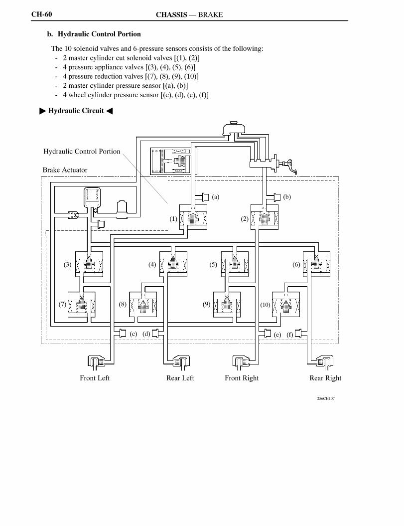
b. Hydraulic Control Portion
The 10 solenoid valves and 6-pressure sensors consists of the following:- 2 master cylinder cut solenoid valves [(1), (2)]- 4 pressure appliance valves [(3), (4), (5), (6)]- 4 pressure reduction valves [(7), (8), (9), (10)]- 2 master cylinder pressure sensor [(a), (b)]- 4 wheel cylinder pressure sensor [(c), (d), (e), (f)]
" Hydraulic CircuitA
256CH107
Hydraulic Control Portion
Brake Actuator
Front Left Rear Left Front Right Rear Right
(7) (8) (9) (10)
(3) (4) (5) (6)
(a)
(1) (2)
(b)
(c) (d) (e) (f)
NCF277U
CH
CHASSIS—BRAKE CH-61
c. Hydraulic Power Source Portion
i) General
The hydraulic power source portion consists of pump, pumpmotor, accumulator, relief valve, 2 motorrelays, and accumulator pressure sensor.
ii) Accumulator
Inside the accumulator of the RX400h, as same as the previous model, the high-pressurized nitrogengas is charged and sealed. On the RX400h, metallic bellows-formed tube is used, in order to enhancethe gastight performance of the accumulator.
277CH124
Bellows-formedNitrogen Gas
Accumulator
A ACross Section
A
A
iii) Pump and Pump Motor
Aplunger type pump is used. This pump is operated by the rotation of the camshaft driven by themotor,and then supplies high-pressurized fluid to the accumulator.
277CH125
Camshaft PumpPump Motor
A ACross SectionA
A
NCF277U
CHASSIS—BRAKECH-62
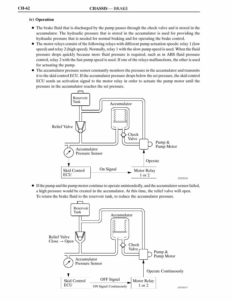
iv) Operation
D The brake fluid that is discharged by the pump passes through the check valve and is stored in theaccumulator. The hydraulic pressure that is stored in the accumulator is used for providing thehydraulic pressure that is needed for normal braking and for operating the brake control.
D The motor relays consist of the following relays with different pump actuation speeds: relay 1 (lowspeed) and relay 2 (high speed). Normally, relay 1with the slow pump speed is used.When the fluidpressure drops quickly because more fluid pressure is required, such as in ABS fluid pressurecontrol, relay 2 with the fast pump speed is used. If one of the relays malfunctions, the other is usedfor actuating the pump.
D The accumulator pressure sensor constantly monitors the pressure in the accumulator and transmitsit to the skid control ECU. If the accumulator pressure drops below the set pressure, the skid controlECU sends an activation signal to the motor relay in order to actuate the pump motor until thepressure in the accumulator reaches the set pressure.
255CH136
Accumulator
CheckValve
ReservoirTank
Pump &Pump Motor
Operate
Skid ControlECU
Motor Relay1 or 2
On Signal
AccumulatorPressure Sensor
Relief Valve
D If the pumpand the pumpmotor continue tooperate unintendedly, and the accumulator sensor failed,a high pressure would be created in the accumulator. At this time, the relief valve will open.To return the brake fluid to the reservoir tank, to reduce the accumulator pressure.
255CH137
Accumulator
CheckValve
ReservoirTank
Pump &Pump Motor
Operate Continuously
Skid ControlECU
Motor Relay1 or 2
OFF Signal
AccumulatorPressure Sensor
Relief ValveClose! Open
ON Signal Continuously

NCF277U
CH
CHASSIS—BRAKE CH-63
D If the accumulator pressure drops abnormally to a level below the pressure set at the ECU, the skidcontrol ECU illuminates the brake systemwarning light, the ECBwarning light, ABSwarning lightand the master warning light. Then, a warning message appears on the multi-information displayin the combination meter, and the skid control warning buzzer sounds to alert the driver of theabnormal hydraulic pressure.
255CH138
Accumulator
CheckValve
ReservoirTank
Pump &Pump Motor
Skid ControlECU
AccumulatorPressure Sensor
Combination Meter Brake System & ECB System & ABS & MasterWarning Light: Turn ON
Multi-information Display: Warning Message Appears
Skid Control Warning Buzzer: Sound Continuously

NCF277U
CHASSIS—BRAKE
Service Tip
CH-64
2) Brake Pedal Stroke Sensor
This sensor, which contains a contact type variable resistor, detects the extent of the brake pedal strokeand transmits it to the skid control ECU.
277CH150
Brake PedalStroke Sensor
Sensor Shaft Return Spring
Lever Contacts
Brake Pedal A ACross Section
A
A
255CH164
Voltage SKS2
SKS1
Sensor Lever Rotational Angle
15_ 0 60_0
1
5
D To install a brake pedal stroke sensor, which is available as a service part, perform as follows:The sensor lever is secured with a pin to “0” stroke. (Do not detach the pin until the installationhas been completed.)In this state, install the sensor on the brake pedal (in the OFF state) on the vehicle.After completing the installation, firmly press the brake pedal once to break off the pin that issecuring the sensor in place.Make sure the broken pin does not remain in the sensor lever.
D After replacing the brake pedal stroke sensor, initialization of brake pedal stroke sensor must berequired on the skid control ECU side.
D For the actual procedure, refer to the 2006 LEXUS RX400h Repair Manual (Pub. No. RM1138U).

NCF277U
CH
CHASSIS—BRAKE
255CH141
Service Tip
CH-65
3) Stroke Simulator
The stroke simulator is located between the master cylinder and the brake actuator. It generates a pedalstroke in accordance with the driver’s pedal effort during braking. Containing 2 types of coil springs withdifferent spring constants, the stroke simulator provides pedal stroke characteristics in 2 stages in relationto the master cylinder pressure.
277CH140
Two-positionSolenoid Valve
A ACross Section
A
A
4) Yaw Rate Sensor
Adeceleration rate sensor is built into the yawratesensor. This sensor detects the yaw rate and lateralacceleration, and sends this signal to the skidcontrol ECU.
After replacing the yaw rate sensor or the skid control ECU, initialization of the deceleration sensorand yaw rate sensor is required.For the actual procedure, refer to the 2006 LEXUS RX400h Repair Manual (Pub. No. RM1138U).

NCF277U
CHASSIS—BRAKE
277CH126
Service Tip
CH-66
5) Steering Angle Sensor
This steering angle sensor detects the steeringdirection and angle, and sends this signal to theskid control ECU.The sensor contains two gears for detecting therotational movement. The magnetic field of theMRE (Magnetic Resistance Element), which isbuilt into these gears, changes as the gears rotate.The change in the magnetic field causes theresistance of the sensor to change, which isdetected by the skid control ECUin the formof therotational angle of the steering.
6) Power Source Backup Unit
D Thepower source backupunit is usedas anauxiliary power source, inorder to supply power to thebrakesystem in a stable manner.
D This unit contains 21 capacitor cells, which store an electrical charge provided by the (12V) vehiclepower supply. When the voltage of the (12V) vehicle power supply drops, the electrical charge storedin the capacitor cells is used as an auxiliary power supply to the brake system.
277CH127
Control Board
Capacitor Cell
Immediately after the ignition switch is turned OFF, this unit is in the discharging state, and some voltageremains in the capacitors. Therefore, make sure to check for residual voltage and discharge it if necessary,before removing the power source backup unit from the vehicle or opening and inspecting the insideof the power source backup unit case.For details, refer to the LEXUS 2006 RX400h Repair Manual (Pub. No. RM1138U).

NCF277U
CH
CHASSIS—BRAKE CH-67
System Operation
1) Normal Brake Operation (With Regenerative Brake Cooperative Control)
a. General
D During normal braking, the master cylinder cut solenoid valves are closed and the fluid pressurecircuits to the wheel cylinders remain independent. Accordingly, the fluid pressure generated by themaster cylinder will not directly cause the wheel cylinders to actuate.
D Theskid control ECUcalculates thebraking force required by thedriver in accordancewith the signalsreceived from the master cylinder pressure sensors and the brake pedal stroke sensor. Then, the skidcontrol ECUcalculates the regenerative brake force valueout of the required brake force and transmitsthe calculated value to the THS ECU. Upon receiving the value, the THS ECU generates aregenerative brake force.At the same time, theTHSECUtransmits the actual regenerative brake forcevalue to the skid control ECU. The skid control ECU controls the solenoid valves in order to causethe hydraulic brake system to generate a brake force value (which is obtained by subtracting theregenerative brake force from the brake force value required by the driver).
" System DiagramA
255CH144
Brake Actuator
VSC WarningBuzzer
Stop Light Switch
THS ECU
Brake PedalStroke Simulator
Master CylinderPressure Sensors
Skid ControlECU
Brake Actuator
Wheel CylinderPressure Sensors
BEAN(Instrument Panel Bus)
Combination Meter
ECB Warning Light
Gateway ECUCAN
RegenerativeBrake
Pressure ApplianceSolenoid Valves
Brake PedalStroke Sensor
Pressure ReductionSolenoid Valves
Brake SystemWarning Light
NCF277U
CHASSIS—BRAKECH-68
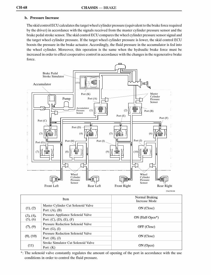
b. Pressure Increase
Theskid controlECUcalculates the targetwheel cylinder pressure (equivalent to thebrake force requiredby the driver) in accordance with the signals received from the master cylinder pressure sensor and thebrake pedal stroke sensor. The skid control ECUcompares thewheel cylinder pressure sensor signal andthe target wheel cylinder pressure. If the target wheel cylinder pressure is lower, the skid control ECUboosts the pressure in the brake actuator. Accordingly, the fluid pressure in the accumulator is fed intothe wheel cylinder. Moreover, this operation is the same when the hydraulic brake force must beincreased in order to effect cooperative control in accordance with the changes in the regenerative brakeforce.
256CH108
Front RightRear Left Rear RightFront Left
Pump
(11)
Brake PedalStroke Simulator
Accumulator
(5)
(2)
(3) (4)
(8)(7)
(6)
(10)(9)
WheelCylinderPressureSensor
Port (A)
Port (B)
Port (G)Port (J)
Port (E)
Port (K)
Port (F)Port (C)
Port (I)Port (H)
WheelCylinderPressureSensor
AccumulatorPressureSensor
MasterCylinderPressureSensor
(1)
Port (D)
Item Normal BrakingItem Normal BrakingIncrease Mode
(1) (2)Master Cylinder Cut Solenoid Valve
ON (Close)(1), (2) Port: (A), (B) ON (Close)
(3), (4), Pressure Appliance Solenoid ValveON (Half Open*)(3), (4),
(5), (6) Port: (C), (D), (E), (F) ON (Half-Open*)
(7) (9)Pressure Reduction Solenoid Valve
OFF (Close)(7), (9) Port: (G), (I) OFF (Close)
(8) (10)Pressure Reduction Solenoid Valve
ON (Close)(8), (10) Port: (H), (J) ON (Close)
(11)Stroke Simulator Cut Solenoid Valve
ON (Open)(11) Port: (K) ON (Open)
*: The solenoid valve constantly regulates the amount of opening of the port in accordance with the useconditions in order to control the fluid pressure.

NCF277U
CH
CHASSIS—BRAKE CH-69
c. Holding
Theskid controlECUcalculates the targetwheel cylinder pressure (equivalent to thebrake force requiredby the driver) in accordance with the signals received from the master cylinder pressure sensor and thebrake pedal stroke sensor.The skid control ECU compares the wheel cylinder pressure signal with the target wheel cylinderpressure. If they are equal, the skid control ECU controls the brake actuator in the hold state.Accordingly, the wheel cylinder will be held at a constant pressure.
256CH109
Front RightRear Left Rear RightFront Left
Pump
(11)
Brake PedalStroke Simulator
Accumulator
(5)
(2)
(3) (4)
(8)(7)
(6)
(10)(9)
WheelCylinderPressureSensor
Port (A)
Port (B)
Port (G)Port (J)
Port (E)
Port (K)
Port (F)Port (C)
Port (I)Port (H)
WheelCylinderPressureSensor
AccumulatorPressureSensor
MasterCylinderPressureSensor
(1)
Port (D)
Item Normal BrakingItem Normal BrakingHold Mode
(1) (2)Master Cylinder Cut Solenoid Valve
ON (Close)(1), (2) Port: (A), (B) ON (Close)
(3), (4), Pressure Appliance Solenoid ValveOFF (Close)(3), (4),
(5), (6) Port: (C), (D), (E), (F) OFF (Close)
(7) (9)Pressure Reduction Solenoid Valve
OFF (Close)(7), (9) Port: (G), (I) OFF (Close)
(8) (10)Pressure Reduction Solenoid Valve
ON (Close)(8), (10) Port: (H), (J) ON (Close)
(11)Stroke Simulator Cut Solenoid Valve
ON (Open)(11) Port: (K) ON (Open)

NCF277U
CHASSIS—BRAKECH-70
d. Pressure Reduce
Theskid controlECUcalculates the targetwheel cylinder pressure (equivalent to thebrake force requiredby the driver) in accordance with the signals received from the master cylinder pressure sensor and thebrake pedal stroke sensor.The skid control ECU compares the wheel cylinder pressure signal with the target wheel cylinderpressure. If the target wheel cylinder pressure is higher, the skid control ECU reduces the pressure in thebrake actuator. Accordingly, the pressure in the wheel cylinder decreases.Moreover, this operation is the samewhen the hydraulic brake force must be decreased in order to effectcooperative control in accordance with the changes in the regenerative brake force.
256CH110
Front RightRear Left Rear RightFront Left
Pump
(11)
Brake PedalStroke Simulator
Accumulator
(5)
(2)
(3) (4)
(8)(7)
(6)
(10)(9)
WheelCylinderPressureSensor
Port (A)
Port (B)
Port (G)Port (J)
Port (E)
Port (K)
Port (F)Port (C)
Port (I)Port (H)
WheelCylinderPressureSensor
AccumulatorPressureSensor
MasterCylinderPressureSensor
(1)
Port (D)
Item Normal BrakingItem Normal BrakingReduce Mode
(1) (2)Master Cylinder Cut Solenoid Valve
ON (Close)(1), (2) Port: (A), (B) ON (Close)
(3), (4), Pressure Appliance Solenoid ValveOFF (Close)(3), (4),
(5), (6) Port: (C), (D), (E), (F) OFF (Close)
(7) (9)Pressure Reduction Solenoid Valve
ON (Half Open*)(7), (9) Port: (G), (I) ON (Half-Open*)
(8) (10)Pressure Reduction Solenoid Valve
ON (Half Open*)(8), (10) Port: (H), (J) ON (Half-Open*)
(11)Stroke Simulator Cut Solenoid Valve
ON (Open)(11) Port: (K) ON (Open)
*: The solenoid valve constantly regulates the amount of opening of the port in accordance with the useconditions in order to control the fluid pressure.
NCF277U
CH
CHASSIS—BRAKE CH-71
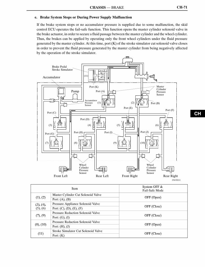
e. Brake System Stops or During Power Supply Malfunction
If the brake system stops or no accumulator pressure is supplied due to some malfunction, the skidcontrol ECU operates the fail-safe function. This function opens the master cylinder solenoid valve inthe brake actuator, in order to secure a fluid passage between themaster cylinder and the wheel cylinder.Thus, the brakes can be applied by operating only the front wheel cylinders under the fluid pressuregenerated by the master cylinder. At this time, port (K) of the stroke simulator cut solenoid valve closesin order to prevent the fluid pressure generated by the master cylinder from being negatively affectedby the operation of the stroke simulator.
256CH111
Front RightRear Left Rear RightFront Left
Pump
(11)
Brake PedalStroke Simulator
Accumulator
(5)
(2)
(3) (4)
(8)(7)
(6)
(10)(9)
WheelCylinderPressureSensor
Port (A)
Port (B)
Port (G)Port (J)
Port (E)
Port (K)
Port (F)Port (C)
Port (I)Port (H)
WheelCylinderPressureSensor
AccumulatorPressureSensor
MasterCylinderPressureSensor
(1)
Port (D)
Item System OFF &Item System OFF &Fail-Safe Mode
(1) (2)Master Cylinder Cut Solenoid Valve
OFF (Open)(1), (2) Port: (A), (B) OFF (Open)
(3), (4), Pressure Appliance Solenoid ValveOFF (Close)(3), (4),
(5), (6) Port: (C), (D), (E), (F) OFF (Close)
(7) (9)Pressure Reduction Solenoid Valve
OFF (Close)(7), (9) Port: (G), (I) OFF (Close)
(8) (10)Pressure Reduction Solenoid Valve
OFF (Open)(8), (10) Port: (H), (J) OFF (Open)
(11)Stroke Simulator Cut Solenoid Valve
OFF (Close)(11) Port: (K) OFF (Close)
NCF277U
CHASSIS—BRAKECH-72
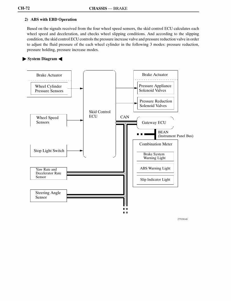
2) ABS with EBD Operation
Based on the signals received from the four wheel speed sensors, the skid control ECU calculates eachwheel speed and deceleration, and checks wheel slipping conditions. And according to the slippingcondition, the skid control ECUcontrols the pressure increase valve and pressure reduction valve in orderto adjust the fluid pressure of the each wheel cylinder in the following 3 modes: pressure reduction,pressure holding, pressure increase modes.
" System DiagramA
277CH148
Brake Actuator
Stop Light Switch
Slip Indicator Light
Wheel CylinderPressure Sensors
Skid ControlECU
Brake Actuator
Wheel SpeedSensors
BEAN(Instrument Panel Bus)
Combination Meter
ABS Warning Light
Gateway ECUCAN
Pressure ApplianceSolenoid Valves
Yaw Rate andDecelerator RateSensor
Pressure ReductionSolenoid Valves
Brake SystemWarning Light
Steering AngleSensor

NCF277U
CH
CHASSIS—BRAKE
Port A
PressureApplianceValve
Port B
PressureReductionValve
To WheelCylinder
From WheelCylinder
ToReservoir
Port A
PressureApplianceValve
Port B
PressureReductionValve
To WheelCylinder
From WheelCylinder
ToReservoir
CH-73
Not Activated Normal Braking — —
Activated Increase Mode Holding Mode Reduction Mode
HydraulicCircuit
255CH151 255CH152 255CH153
Front
Pressure ApplianceSolenoid Valve (Port A) ON (Half-Open*) OFF (Close) OFF (Close)
FrontPressure Reduction
Solenoid Valve (Port B) OFF (Close) OFF (Close) ON (Half-Open*)
HydraulicCircuit
255CH159 255CH160 255CH161
Rear
Pressure ApplianceSolenoid Valve (Port A) ON (Half-Open*) OFF (Close) OFF (Close)
RearPressure Reduction
Solenoid Valve (Port B) ON (Close) ON (Close) ON (Half-Open*)
Wheel Cylinder Pressure Increase Hold Reduction
*: The solenoid valve constantly regulates the amount of opening of the port in accordance with the useconditions in order to control the fluid pressure.
NCF277U
CHASSIS—BRAKECH-74
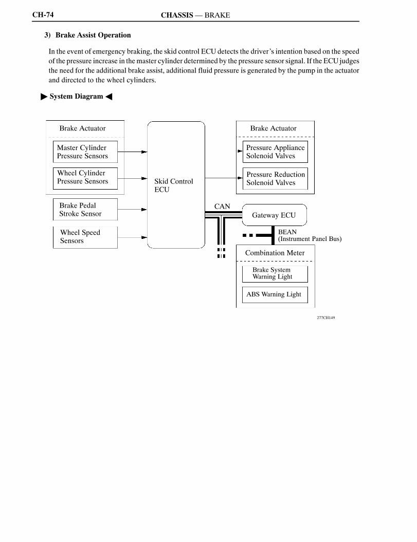
3) Brake Assist Operation
In the event of emergency braking, the skid control ECU detects the driver’s intention based on the speedof the pressure increase in themaster cylinder determined by the pressure sensor signal. If the ECU judgesthe need for the additional brake assist, additional fluid pressure is generated by the pump in the actuatorand directed to the wheel cylinders.
" System DiagramA
277CH149
Brake Actuator
Brake PedalStroke Sensor
Master CylinderPressure Sensors
Skid ControlECU
Brake Actuator
Wheel CylinderPressure Sensors
BEAN(Instrument Panel Bus)
Combination Meter
ABS Warning Light
Gateway ECUCAN
Pressure ApplianceSolenoid Valves
Pressure ReductionSolenoid Valves
Brake SystemWarning Light
Wheel SpeedSensors

NCF277U
CH
CHASSIS—BRAKE CH-75
256CH112
Front RightRear Left Rear RightFront Left
Pump
(11)
Brake PedalStroke Simulator
Accumulator
(5)
(2)
(3) (4)
(8)(7)
(6)
(10)(9)
WheelCylinderPressureSensor
Port (A)
Port (B)
Port (G)Port (J)
Port (E)
Port (K)
Port (F)Port (C)
Port (I)Port (H)
WheelCylinderPressureSensor
AccumulatorPressureSensor
MasterCylinderPressureSensor
(1)
Port (D)
Item Normal Braking Brake AssistItem Normal BrakingIncrease Mode
Brake AssistActivated
(1) (2)Master Cylinder Cut Solenoid Valve
ON (Close) ON (Close)(1), (2) Port: (A), (B) ON (Close) ON (Close)
(3), (4), Pressure Appliance Solenoid ValveON (Half Open*) ON (Half Open*)(3), (4),
(5), (6) Port: (C), (D), (E), (F) ON (Half-Open*) ON (Half-Open*)
(7) (9)Pressure Reduction Solenoid Valve
OFF (Close) OFF (Close)(7), (9) Port: (G), (I) OFF (Close) OFF (Close)
(8) (10)Pressure Reduction Solenoid Valve
ON (Close) ON (Close)(8), (10) Port: (H), (J) ON (Close) ON (Close)
(11)Stroke Simulator Cut Solenoid Valve
ON (Open) ON (Open)(11) Port: (K) ON (Open) ON (Open)
*: The solenoid valve constantly regulates the amount of opening of the port in accordance with the useconditions in order to control the fluid pressure.
NCF277U
CHASSIS—BRAKECH-76
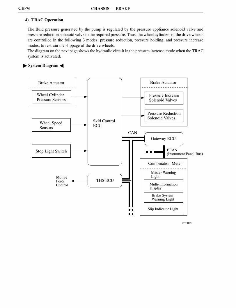
4) TRAC Operation
The fluid pressure generated by the pump is regulated by the pressure appliance solenoid valve andpressure reduction solenoid valve to the required pressure. Thus, the wheel cylinders of the drive wheelsare controlled in the following 3 modes: pressure reduction, pressure holding, and pressure increasemodes, to restrain the slippage of the drive wheels.The diagram on the next page shows the hydraulic circuit in the pressure increase mode when the TRACsystem is activated.
" System DiagramA
277CH154
Brake Actuator
Skid ControlECU
Brake Actuator
Wheel CylinderPressure Sensors
BEAN(Instrument Panel Bus)
Combination Meter
Multi-informationDisplay
Gateway ECUCAN
Pressure IncreaseSolenoid Valves
Pressure ReductionSolenoid Valves
Master WarningLight
Wheel SpeedSensors
Stop Light Switch
MotiveForceControl
Slip Indicator Light
Brake SystemWarning Light
THS ECU

NCF277U
CH
CHASSIS—BRAKE CH-77
" 2WDModelA
277CH155
Front RightRear Left Rear RightFront Left
Pump
(11)
Brake PedalStroke Simulator
Accumulator
(5)
(2)
(3) (4)
(8)(7)
(6)
(10)(9)
WheelCylinderPressureSensor
Port (A)
Port (B)
Port (G)Port (J)
Port (E)
Port (K)
Port (F)Port (C)
Port (I)Port (H)
WheelCylinderPressureSensor
AccumulatorPressureSensor
MasterCylinderPressureSensor
(1)
Port (D)
Increase Mode
TRAC notTRAC Activated
Item TRAC notActivated Increase
ModeHoldMode
ReductionMode
(1) (2)Master Cylinder Cut Solenoid Valve ON ON ON ON(1), (2) Port: (A), (B)
ON(Close)
ON(Close)
ON(Close)
ON(Close)
(3), (5)Pressure ApplianceSolenoid Valve OFF
(Close)ON
(Half Open*)OFF(Close)
OFF(Close)
F t
(3), (5)Port: (C), (E) (Close) (Half-Open*) (Close) (Close)
FrontBrake
(7), (9)Pressure ReductionSolenoid Valve OFF
(Close)OFF(Close)
OFF(Close)
ON(Half Open*)
(7), (9)Port: (G), (I) (Close) (Close) (Close) (Half-Open*)
Wheel Cylinder Pressure Increase Hold Reduction
(4), (6)Pressure ApplianceSolenoid Valve OFF
(Close)OFF(Close)
OFF(Close)
OFF(Close)
R
(4), (6)Port: (D), (F) (Close) (Close) (Close) (Close)
RearBrake
(8), (10)Pressure ReductionSolenoid Valve OFF
(Open)OFF(Open)
OFF(Open)
OFF(Open)
(8), (10)Port: (H), (J) (Open) (Open) (Open) (Open)
Wheel Cylinder Pressure
(11)Stroke Simulator Cut Solenoid Valve ON ON ON ON(11) Port: (K)
ON(Open)
ON(Open)
ON(Open)
ON(Open)
*: The solenoid valve constantly regulates the amount of opening of the port in accordance with the useconditions in order to control the fluid pressure.
NCF277U
CHASSIS—BRAKECH-78
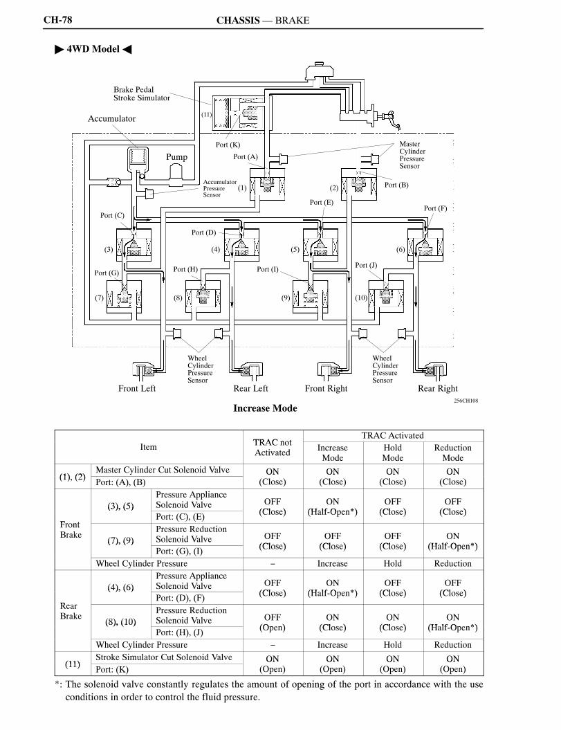
" 4WDModelA
256CH108
Front RightRear Left Rear RightFront Left
Pump
(11)
Brake PedalStroke Simulator
Accumulator
(5)
(2)
(3) (4)
(8)(7)
(6)
(10)(9)
WheelCylinderPressureSensor
Port (A)
Port (B)
Port (G)Port (J)
Port (E)
Port (K)
Port (F)Port (C)
Port (I)Port (H)
WheelCylinderPressureSensor
AccumulatorPressureSensor
MasterCylinderPressureSensor
(1)
Port (D)
Increase Mode
TRAC notTRAC Activated
Item TRAC notActivated Increase
ModeHoldMode
ReductionMode
(1) (2)Master Cylinder Cut Solenoid Valve ON ON ON ON(1), (2) Port: (A), (B)
ON(Close)
ON(Close)
ON(Close)
ON(Close)
(3), (5)Pressure ApplianceSolenoid Valve OFF
(Close)ON
(Half Open*)OFF(Close)
OFF(Close)
F t
(3), (5)Port: (C), (E) (Close) (Half-Open*) (Close) (Close)
FrontBrake
(7), (9)Pressure ReductionSolenoid Valve OFF
(Close)OFF(Close)
OFF(Close)
ON(Half Open*)
(7), (9)Port: (G), (I) (Close) (Close) (Close) (Half-Open*)
Wheel Cylinder Pressure Increase Hold Reduction
(4), (6)Pressure ApplianceSolenoid Valve OFF
(Close)ON
(Half Open*)OFF(Close)
OFF(Close)
R
(4), (6)Port: (D), (F) (Close) (Half-Open*) (Close) (Close)
RearBrake
(8), (10)Pressure ReductionSolenoid Valve OFF
(Open)ON
(Close)ON
(Close)ON
(Half Open*)(8), (10)
Port: (H), (J) (Open) (Close) (Close) (Half-Open*)
Wheel Cylinder Pressure Increase Hold Reduction
(11)Stroke Simulator Cut Solenoid Valve ON ON ON ON(11) Port: (K)
ON(Open)
ON(Open)
ON(Open)
ON(Open)
*: The solenoid valve constantly regulates the amount of opening of the port in accordance with the useconditions in order to control the fluid pressure.

NCF277U
CH
CHASSIS—BRAKE CH-79
5) VSC Operation
a. General
The VSC function controls the solenoid valves in order to send the fluid pressure stored in theaccumulator to the brake wheel cylinders at the respective wheels, through routes that are different fromthose used during normal braking. Thus, the function operates in the following 3 modes: pressurereduction, pressure holding, and pressure increase. As a result, the tendency of the front wheels or therear wheels to skid is restrained.
" System DiagramA
277CH128
Brake Actuator
VSC WarningBuzzer
THS ECUEPS ECU
Wheel CylinderPressure Sensors
Skid ControlECU
Brake Actuator
BEAN(Instrument Panel Bus)
Combination Meter
Gateway ECUCAN
Pressure IncreaseSolenoid Valves
Pressure ReductionSolenoid Valves
Stop Light Switch
Wheel SpeedSensors
Yaw Rate andDecelerator RateSensor
Steering AngleSensor
Master Warning Light
Multi-informationDisplay
Brake SystemWarning Light
AssistTorqueControl
MotiveForceControl
Slip Indicator Light
NCF277U
CHASSIS—BRAKECH-80
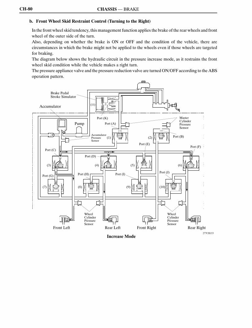
b. Front Wheel Skid Restraint Control (Turning to the Right)
In the front wheel skid tendency, thismanagement function applies the brake of the rearwheels and frontwheel of the outer side of the turn.Also, depending on whether the brake is ON or OFF and the condition of the vehicle, there arecircumstances in which the brake might not be applied to the wheels even if those wheels are targetedfor braking.The diagram below shows the hydraulic circuit in the pressure increase mode, as it restrains the frontwheel skid condition while the vehicle makes a right turn.The pressure appliance valve and the pressure reduction valve are turnedON/OFFaccording to theABSoperation pattern.
277CH153
Front RightRear Left Rear RightFront Left
Pump
(11)
Brake PedalStroke Simulator
Accumulator
(5)
(2)
(3) (4)
(8)(7)
(6)
(10)(9)
WheelCylinderPressureSensor
Port (A)
Port (B)
Port (G)Port (J)
Port (E)
Port (K)
Port (F)Port (C)
Port (I)Port (H)
WheelCylinderPressureSensor
AccumulatorPressureSensor
MasterCylinderPressureSensor
(1)
Port (D)
Increase Mode

NCF277U
CH
CHASSIS—BRAKE CH-81
VSC notVSC Activated
Item VSC notActivated Increase Mode Hold
ModeReductionMode
(1), (2)Master Cylinder Cut SolenoidValve ON
(Close)ON
(Close)ON
(Close)ON
(Close)(1), (2)
Port: (A), (B) (Close) (Close) (Close) (Close)
(3)Pressure ApplianceSolenoid Valve OFF
(Close)ON
(Half Open*)OFF(Close)
OFF(Close)
(3)Port: (C) (Close) (Half-Open*) (Close) (Close)
(5)Pressure ApplianceSolenoid Valve OFF
(Close)OFF(Close)
OFF(Close)
OFF(Close)
(5)Port: (E) (Close) (Close) (Close) (Close)
FrontBrake (7)
Pressure ReductionSolenoid Valve OFF
(Close)OFF(Close)
OFF(Close)
ON(Half Open*)Brake (7)
Port: (G) (Close) (Close) (Close) (Half-Open*)
(9)Pressure ReductionSolenoid Valve OFF
(Close)OFF(Close)
OFF(Close)
OFF(Close)
(9)Port: (I) (Close) (Close) (Close) (Close)
WheelCylinder
RightCylinderPressure Left Increase Hold Reduction
(4)Pressure ApplianceSolenoid Valve OFF
(Close)OFF(Close)
OFF(Close)
OFF(Close)
(4)Port: (D) (Close) (Close) (Close) (Close)
(6)Pressure ApplianceSolenoid Valve OFF
(Close)ON
(Half Open*)OFF(Close)
OFF(Close)
(6)Port: (F) (Close) (Half-Open*) (Close) (Close)
RearBrake (8)
Pressure ReductionSolenoid Valve OFF
(Open)ON
(Close)OFF(Open)
ON(Half Open*)Brake (8)
Port: (H) (Open) (Close) (Open) (Half-Open*)
(10)Pressure ReductionSolenoid Valve OFF
(Open)ON
(Close)ON
(Close)ON
(Half Open*)(10)
Port: (J) (Open) (Close) (Close) (Half-Open*)
WheelCylinder
RightIncrease Hold ReductionCylinder
Pressure LeftIncrease Hold Reduction
(11)Stroke Simulator Cut SolenoidValve ON
(Open)ON
(Open)ON
(Open)ON
(Open)(11)
Port: (K) (Open) (Open) (Open) (Open)
*: The solenoid valve constantly regulates the amount of opening of the port in accordance with the useconditions in order to control the fluid pressure.

NCF277U
CHASSIS—BRAKECH-82
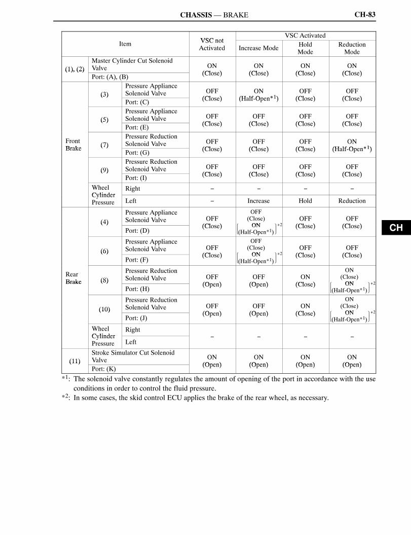
c. Rear Wheel Skid Restraint Control (Turning to the Right)
In rear wheel skid tendency, this management function applies the brake of the front and rear wheels ofthe outer circle of the turn. As an example, the diagram below shows the hydraulic circuit in the pressureincrease mode, as it restrains the rear wheel skid condition while the vehicle make a right turn.As in front wheel skid restrain the pressure appliance valve and the pressure reduction valve are turnedON/OFF according to the ABS operating pattern.
256CH114
Front RightRear Left Rear RightFront Left
Pump
(11)
Brake PedalStroke Simulator
Accumulator
(5)
(2)
(3) (4)
(8)(7)
(6)
(10)(9)
WheelCylinderPressureSensor
Port (A)
Port (B)
Port (G)Port (J)
Port (E)
Port (K)
Port (F)Port (C)
Port (I)Port (H)
WheelCylinderPressureSensor
AccumulatorPressureSensor
MasterCylinderPressureSensor
(1)
Port (D)
Increase Mode
NCF277U
CH
CHASSIS—BRAKE
�
�
�*2�
�
�
�*2�
�
�
�*2�
�
�
�*2�
CH-83
VSC notVSC Activated
Item VSC notActivated Increase Mode Hold
ModeReductionMode
(1), (2)Master Cylinder Cut SolenoidValve ON
(Close)ON
(Close)ON
(Close)ON
(Close)(1), (2)
Port: (A), (B) (Close) (Close) (Close) (Close)
(3)Pressure ApplianceSolenoid Valve OFF
(Close)ON
(Half Open*1)OFF(Close)
OFF(Close)
(3)Port: (C) (Close) (Half-Open*1) (Close) (Close)
(5)Pressure ApplianceSolenoid Valve OFF
(Close)OFF(Close)
OFF(Close)
OFF(Close)
(5)Port: (E) (Close) (Close) (Close) (Close)
FrontBrake (7)
Pressure ReductionSolenoid Valve OFF
(Close)OFF(Close)
OFF(Close)
ON(Half Open*1)Brake (7)
Port: (G) (Close) (Close) (Close) (Half-Open*1)
(9)Pressure ReductionSolenoid Valve OFF
(Close)OFF(Close)
OFF(Close)
OFF(Close)
(9)Port: (I) (Close) (Close) (Close) (Close)
WheelCylinder
RightCylinderPressure Left Increase Hold Reduction
(4)Pressure ApplianceSolenoid Valve OFF
(Close)
OFF(Close)ON
OFF(Close)
OFF(Close)
(4)Port: (D)
(Close) ON(Half-Open*1)
(Close) (Close)
(6)Pressure ApplianceSolenoid Valve OFF
(Close)
OFF(Close)ON
OFF(Close)
OFF(Close)
(6)Port: (F)
(Close) ON(Half-Open*1)
(Close) (Close)
RearBrake (8)
Pressure ReductionSolenoid Valve OFF
(Open)OFF(Open)
ON(Close)
ON(Close)ONBrake (8)
Port: (H)(Open) (Open) (Close) ON
(Half-Open*1)
(10)Pressure ReductionSolenoid Valve OFF
(Open)OFF(Open)
ON(Close)
ON(Close)ON(10)
Port: (J)(Open) (Open) (Close) ON
(Half-Open*1)
WheelCylinder
RightCylinderPressure Left
(11)Stroke Simulator Cut SolenoidValve ON
(Open)ON
(Open)ON
(Open)ON
(Open)(11)Port: (K)
(Open) (Open) (Open) (Open)
*1: The solenoid valve constantly regulates the amount of opening of the port in accordance with the useconditions in order to control the fluid pressure.
*2: In some cases, the skid control ECU applies the brake of the rear wheel, as necessary.
NCF277U
CHASSIS—BRAKECH-84
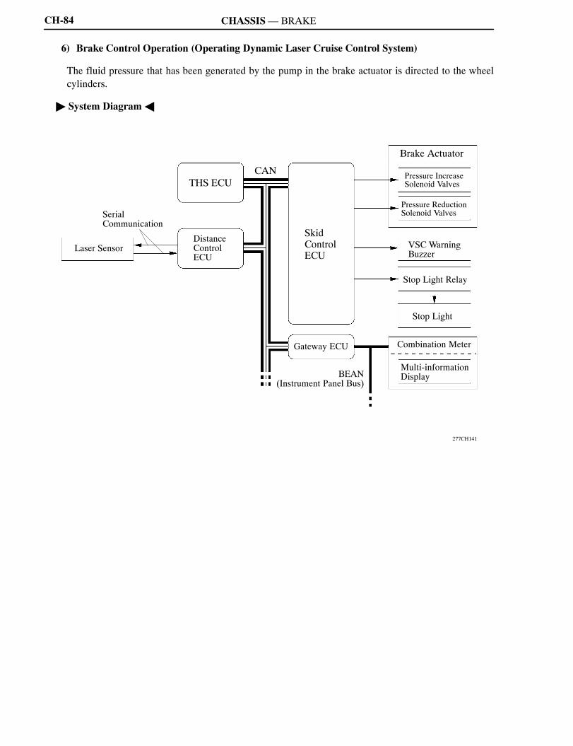
6) Brake Control Operation (Operating Dynamic Laser Cruise Control System)
The fluid pressure that has been generated by the pump in the brake actuator is directed to the wheelcylinders.
" System DiagramA
277CH141
Laser Sensor
SkidControlECU
Brake Actuator
SerialCommunication
BEAN(Instrument Panel Bus)
Combination Meter
Stop Light
Gateway ECU
CAN Pressure IncreaseSolenoid Valves
Pressure ReductionSolenoid Valves
VSC WarningBuzzer
DistanceControlECU
THS ECU
Stop Light Relay
Multi-informationDisplay
NCF277U
CH
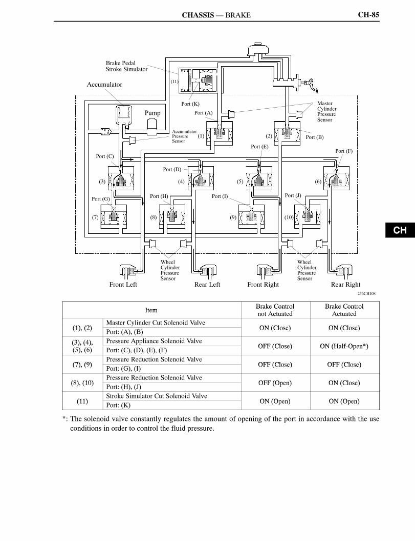
CHASSIS—BRAKE CH-85
256CH108
Front RightRear Left Rear RightFront Left
Pump
(11)
Brake PedalStroke Simulator
Accumulator
(5)
(2)
(3) (4)
(8)(7)
(6)
(10)(9)
WheelCylinderPressureSensor
Port (A)
Port (B)
Port (G)Port (J)
Port (E)
Port (K)
Port (F)Port (C)
Port (I)Port (H)
WheelCylinderPressureSensor
AccumulatorPressureSensor
MasterCylinderPressureSensor
(1)
Port (D)
Item Brake Control Brake ControlItem Brake Controlnot Actuated
Brake ControlActuated
(1) (2)Master Cylinder Cut Solenoid Valve
ON (Close) ON (Close)(1), (2) Port: (A), (B) ON (Close) ON (Close)
(3), (4), Pressure Appliance Solenoid ValveOFF (Close) ON (Half Open*)(3), (4),
(5), (6) Port: (C), (D), (E), (F) OFF (Close) ON (Half-Open*)
(7) (9)Pressure Reduction Solenoid Valve
OFF (Close) OFF (Close)(7), (9) Port: (G), (I) OFF (Close) OFF (Close)
(8) (10)Pressure Reduction Solenoid Valve
OFF (Open) ON (Close)(8), (10) Port: (H), (J) OFF (Open) ON (Close)
(11)Stroke Simulator Cut Solenoid Valve
ON (Open) ON (Open)(11) Port: (K) ON (Open) ON (Open)
*: The solenoid valve constantly regulates the amount of opening of the port in accordance with the useconditions in order to control the fluid pressure.

NCF277U
CHASSIS—BRAKECH-86
Skid Control ECU
VSC
Based on the signals received from the wheel speed sensors, yaw rate sensor, deceleration sensor andsteering sensor, the skid control ECU calculates the skid condition of vehicle condition.If a strong front wheel skid or rear wheel skid tendency is created during an emergency avoidancemaneuver or cornering, and the skid control ECUdetermines that the amount of skid exceeds a prescribedvalue, and controls the motive force and brake fluid pressure.
151CH31
Level of Strong FrontWheel Skid or RearWheel Skid
Brake WheelCylinder FluidPressure*
Motive Force Control Completed
VehicleCondition
High
Motive ForceControl
Time
Open
Start of Motive Force ControlStart of Brake Control Brake Control Completed
*: The wheel cylinder that activates varies depending on the condition of the vehicle.

NCF277U
CH
CHASSIS—BRAKE CH-87
4. Self-Diagnosis
D If a failure occurs in one of the sensors or actuators in the brake system, the skid control ECU informsthe driver of the failure in the brake system by illuminating the ECBwarning light, brake systemwarninglight, or ABS warning light in the combination meter, or displaying a VSC warning message (on themulti-information display).
D At the same time, a DTC (Diagnostic Trouble Code) is stored in memory. The DTC can be accessed byconnecting theSST (09843-18040) between theTc andCGterminals of theDLC3connector andcheckingthe blinking of the ABS warning light, ECB warning light, or the “DIAG VSC” that appears on themulti-information display.Anotherway to access theDTCis to connect a hand-held testerwithCANVIM(dedicated adapter) and read the code that appears on the tester.
D This system has a sensor signal check (test mode) function. This function is activated by connecting theSST (09843-18040) between the Ts and CG terminals of the DLC3 or by connecting a hand-held testerwith CAN VIM (dedicated adapter).
D If the CAN has communication error ECU or sensors, multiple DTCs (Diagnostic Trouble Codes) areoutput simultaneously to indicate the malfunction location.
D All the DTCs have been made to correspond to the SAE controlled codes. Some of the DTCs have beenfurther divided into smaller detection areas than in the past, and new DTCs have been assigned to them.Additionally, DTCs have been added to corresponding to items.
D Three-digit information codes have been provided in the conventional DTC as subset of a primaryfive-digit code. This enables the troubleshooting procedure to further narrow down a trouble area toidentify a problem.
For details on the DTC that are stored in skid control ECUmemory and the DTC that are output through thesensor signal check function, see the 2006 LEXUS RX400h Repair Manual (Pub. No. RM1138U).
5. Fail-Safe
D If a failure occurs in the skid control ECU, sensors, and/or brake actuators, the system continues effectingbrake control by excluding the failed area and using only the areas that are operating normally.
D If the regenerative brake becomes unusable due to a failure in communication with the THSECU, the skidcontrol ECU uses the hydraulic brake force to control the entire braking force.


![REGENERATIVE BRAKING SYSTEM IN ELECTRIC VEHICLES · REGENERATIVE BRAKING SYSTEM IN ELECTRIC VEHICLES ... REGENERATIVE BRAKING SYSTEM ... Regenerative action during braking[9].](https://static.fdocuments.net/doc/165x107/5adccef67f8b9a1a088c7cf0/regenerative-braking-system-in-electric-vehicles-braking-system-in-electric-vehicles.jpg)


