Japanese Guideline for Reduction of Harmonic Emission · 2002-09-25 · Japanese Guideline for...
25
Ver. 1.12 Japanese Guideline for Reduction of Harmonic Emission "Guideline to reduce harmonic emissions caused by electrical and electronic equipment for household and general use" (including the METI* Official Publications for Amendments 1, 2 and 3 to the original publication dated 1994-09-30) November 2001 issued by IEC SC77A Japanese National Committee Note: *1. METI - Ministry of Economy, Trade and Industry. 2. As this English version is an informal document for reference, the original guideline in Japanese language takes precedence, if any difference in the interpretation between them would be anticipated.
Transcript of Japanese Guideline for Reduction of Harmonic Emission · 2002-09-25 · Japanese Guideline for...
Ver. 1.12
Japanese Guideline for Reduction of Harmonic Emission
"Guideline to reduce harmonic emissions caused by electrical and electronic equipment for household and general use"
(including the METI* Official Publications for Amendments 1, 2 and 3 to the original publication dated 1994-09-30)
November 2001
issued by
IEC SC77A Japanese National Committee
Note: *1. METI - Ministry of Economy, Trade and Industry. 2. As this English version is an informal document for reference,
the original guideline in Japanese language takes precedence, if any difference in the interpretation between them would be anticipated.
- 1 -
Japanese Guideline for Reduction of Harmonic Emission
caused by electrical and electronic equipment for household and general use (including the METI* Official Publications for Amendments 1, 2 and 3
to the original publication dated 1994-09-30)
(English version as date of 30 November 2001) 1. Objective The objective of this guideline is, taking into account of the target level for harmonic environment on the public power supply system, to set "the limits for harmonic current emissions by equipment" and other essential conditions such as "the measuring methods" which are needed at the stages when electrical and electronic equipment for household and general use is designed and manufactured. Note 1 : As the target levels for harmonic environments on the public power supply systems,
the following total voltage harmonic distortions were settled to be reasonable in 1987 by the Director-General's consultation committee, "Denryoku Riyou Kiban Kyouka Kondankai" (the explanatory English name is "Committee for consolidating the base For better utilization of the electric power"), of Agency for Natural Resources and Energy in Ministry of International Trade and Industry, which were stated in the Committee Report of May 1987.
The total voltage harmonic distortions for the harmonic environment levels on ; - 6.6 kV electric power distribution system : 5% maximum - electric power transmission or distribution system higher than 7.000V : 3% maximum Note 2 : As the reduction targets of the harmonic current emission, the following reduction amounts from the levels at the year of 1990 were settled in 1990 by the committee "Kouchouha Taisaku Senmon Iinkai" (the explanatory English name is "Special
committee for counterplanning against harmonics") of the corporate body "Denki Kyoudou Kenkyukai" (the explanatory English name is "Electricity Collaboration Study Body"), considering the estimated propagation rate and demand in the market
of the equipment up to the year of 2000, as stated in the Committee Report of June 1990. The reduction amounts in total harmonic emission from the levels at the year of 1990 for;
- equipment for household and general use : 25% - consumers agreed with power supply company: 50% Note 3 : Respecting the spirit of GATT Standard Code (presently, WTO TBT agreement)
to avoid non-tariff barrier made by standards or the like and also considering the above mentioned target levels of the harmonics reduction, this guideline has been
made basically in harmonization with IEC standards (IEC 61000-3-2 and others) and moreover by taking into account of the Japanese proper circumstances.
- 2 -
2. Scope This guideline is applicable to electrical and electronic equipment having a rated input current up to and including 20A per phase and intended to be connected to public power supply systems with nominal voltages equal to and less than 300V. This guideline does not impede to be applied correspondingly as practicable to equipment out of the above category. 3. Definitions For the purpose of the principal terminology used in this guideline, the following definitions apply: 3.1 Public power supply system A public power distribution system including power-outlets for users which is electrically connected with the power supply network owned by an electric power supply company. 3.2 Step-down converter for lighting equipment A converter which generally converts the power frequency to a high frequency and operates lamp(s) at a frequency other than the power supply frequency (hereafter referred to as "step-down converter"). The unit may consist of all or a part of such components as semiconductor elements, transformers, choke coils and capacitors in an integral form or separately. It may include means for dimming, noise suppressing and/or power factor
improvement, etc. 3.3 Self-ballasted lamp
A fluorescent lamp in which a tube, starter and ballast are integrated and not replaceable, and which has an Edison-base cap.
3.4 Lighting equipment A luminaire, a self-ballasted lamp and a lamp control device such as a dimming device, a ballast and a step-down converter. 3.5 Dimming device A device which is capable of controlling the light-output of lamp(s) by means of a dimmer,
change-over switches or other electrical procedure. 3.6 Vacuum cleaner with stepped controls A vacuum cleaner of such a system that the power is controlled by changing the firing
angle stepwise.
- 3 -
3.7 Electronic computer The electronic computer and related equipment specified in Division 52 of Standard Commodity Classification for Japan (Japan Management and Coordination Agency: presently, Ministry of Public Management, Home Affairs, Posts and Telecommunications) 4. Classification of equipment For the purpose of harmonic current limitation, equipment is classified as follows: Class A: Balanced three-phase equipment and all other equipment than the one stated in
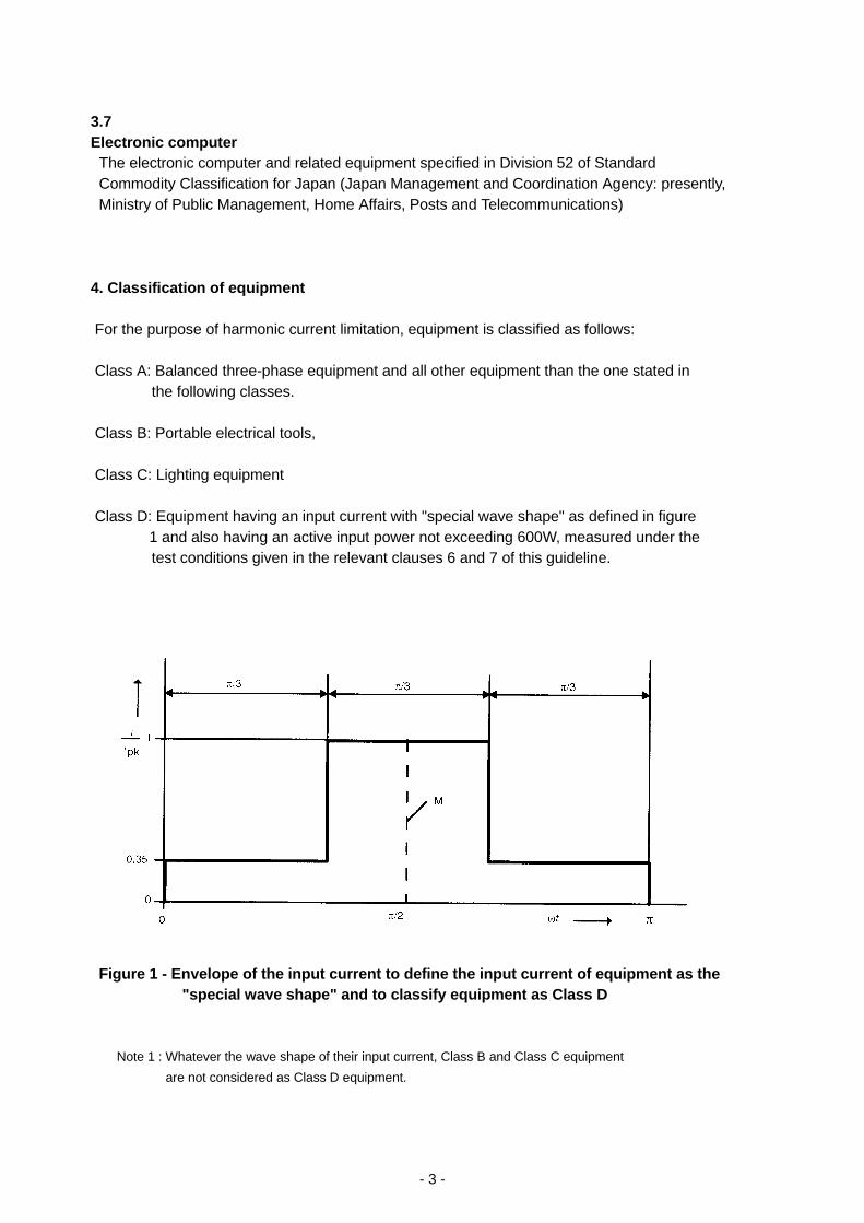
the following classes. Class B: Portable electrical tools, Class C: Lighting equipment Class D: Equipment having an input current with "special wave shape" as defined in figure 1 and also having an active input power not exceeding 600W, measured under the
test conditions given in the relevant clauses 6 and 7 of this guideline.
Figure 1 - Envelope of the input current to define the input current of equipment as the
"special wave shape" and to classify equipment as Class D
Note 1 : Whatever the wave shape of their input current, Class B and Class C equipment are not considered as Class D equipment.
- 4 -
Note 2 : Equipment shall be deemed to be Class D if, under the test conditions given in
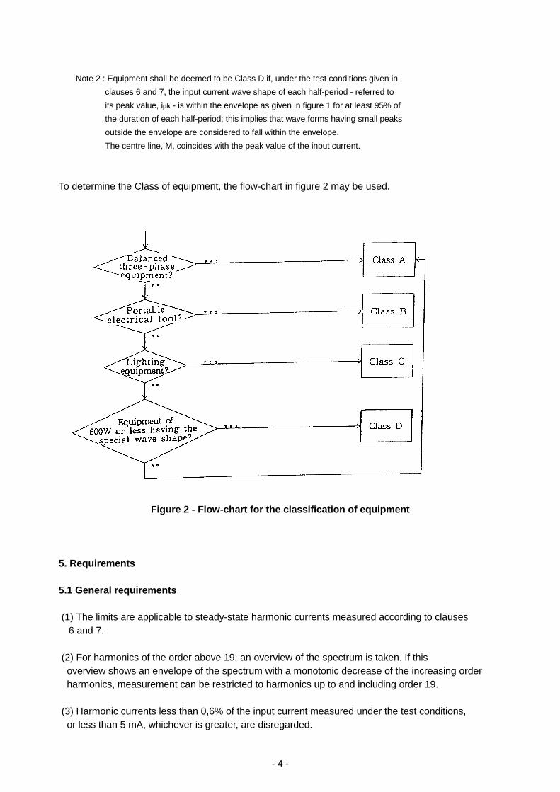
clauses 6 and 7, the input current wave shape of each half-period - referred to its peak value, ipk - is within the envelope as given in figure 1 for at least 95% of the duration of each half-period; this implies that wave forms having small peaks outside the envelope are considered to fall within the envelope. The centre line, M, coincides with the peak value of the input current. To determine the Class of equipment, the flow-chart in figure 2 may be used.
Figure 2 - Flow-chart for the classification of equipment 5. Requirements 5.1 General requirements (1) The limits are applicable to steady-state harmonic currents measured according to clauses
6 and 7.
(2) For harmonics of the order above 19, an overview of the spectrum is taken. If this overview shows an envelope of the spectrum with a monotonic decrease of the increasing order harmonics, measurement can be restricted to harmonics up to and including order 19. (3) Harmonic currents less than 0,6% of the input current measured under the test conditions, or less than 5 mA, whichever is greater, are disregarded.
- 5 -
(4) For transitory harmonic currents, measured according to clauses 6 and 7, the following applies: (a) Harmonic currents lasting for not more than 10 seconds when a piece of equipment is brought into operation or is taken out of operation, manually or automatically, are disregarded. Note: For high-voltage discharge lamps, the limits are not applicable to harmonic currents
generated during the period up to stabilization of operation after starting. (b) The limits are applicable to all other transitory harmonic currents occurring during
the testing of equipment or parts of equipment, in accordance with clauses 6 and 7.
(c) For transitory harmonic currents, values up to 1,5 times the limits are allowed for each harmonic during a maximum of 10% of any observation period of 2,5 minutes. (5) When limits for harmonic currents are given as a function of the fundamental current or active input power, the fundamental currents or the input power shall be measured under the same conditions as those for harmonic-current measurement. (6) When the device or facility is composed of plural items of equipment, each of which has the own power supply plug and the shape of the plug is the type being able to be connected with the public power supply system, and if these are installed in a rack or case or if these form a composite equipment or system, the individual item of equipment is regarded as being connected with the power supply and the limits are applied to each individual equipment. (7) When a composite equipment is consisting of plural items of equipment classified into different classes, the measurements may be carried out on each individual item of equipment and the appropriate limit to each class may be applied, even if the individual item of equipment has no power supply plug. Note: When compliance with this guideline is indicated, "Compliance with the Japanese Harmonics Guideline" shall be stated in the instruction manual or the like. When this guideline is
correspondingly applied to the equipment outside the scope, "Conformity as applicable to the Japanese Harmonics Guideline" shall be stated.
5. 2 Harmonic current limits The limits of harmonic currents generated by each class of equipment shall be as follows. (Unit: Ampere, the r.m.s. value for each harmonic order) Note: W is the value expressing the active input power of equipment in Watt (W)
measured in accordance with the methods of clauses 6 and 7.
- 6 -
5. 2. 1 Limits for Class A equipment For Class A equipment, the harmonics of the input current shall not exceed the values of the "Maximum permissible harmonic current" given in Limit A of table 1. In case of three-phase 200V equipment, Limit A of table 1-1 is applied. 5. 2. 2 Limits for Class B equipment For Class B equipment, the harmonics of the input current shall not exceed the "Maximum permissible harmonic current" given in Limit A of table 1 multiplied by a factor 1,5. In the case of three-phase 200V equipment classified in Class B, the values given in Limit A of table 1-1 multiplied by a factor 1,5 are applied. 5. 2. 3 Limits for Class C equipment (1) For Class C equipment, the harmonics of the input current shall not exceed the "Maximum
values expressed as a percentage of the input current at the fundamental frequency for lighting equipment" given in Limit C of table 2.
(2) No limits shall be applied to lighting equipment having an active input power of less than or
equal to 35 W. However, the self-blasted fluorescent lamps having less than or equal to 35W shall satisfy either of the requirements specified below. This provision became effective in January 1999. (a) The harmonics of the input current shall not exceed the "power-proportional limits and maximum permissible harmonic current" of Limit D indicated in table 3. (b) The third harmonic current, expressed as a percentage of the fundamental current, shall not
exceed 86% and the fifth shall not exceed 61%; moreover, the waveform of the input current shall be such that it begins to flow before or at 60 degrees, has its last peak (if there are several peaks per half period) before or at 65 degrees and does not stop flowing before 90 degrees, where the zero crossing of the fundamental supply voltage is assumed to be at zero degree. (3) The limit values for dimming devices shall be as follows:
The harmonic currents of the dimming device built into a discharge lamp luminaire employing a control system other than the phase control system shall not exceed the fundamental current
value at the maximum load multiplied by the "maximum value expressed as a percentage of the input current at the fundamental frequency" given in Limit C of table 2. Note: The limits are not applied to independent dimming devices and built-in dimming devices
incorporated into incandescent lamp luminaires or into discharge lamp luminaires of the phase control system. (4) If various kinds of lamp control devices are built into one luminaire and the plural tables for
the limits are applied, the measurements are in principle carried out on each lamp control device and the respective limit value is applied.
- 7 -
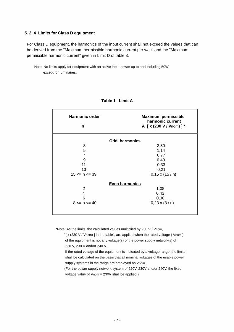
5. 2. 4 Limits for Class D equipment For Class D equipment, the harmonics of the input current shall not exceed the values that can be derived from the "Maximum permissible harmonic current per watt" and the "Maximum permissible harmonic current" given in Limit D of table 3. Note: No limits apply for equipment with an active input power up to and including 50W,
except for Iuminaires.
Table 1 Limit A
Harmonic order Maximum permissible
harmonic current n A [ x (230 V / Vnom) ] *
Odd harmonics
3 2,30 5 1,14
7 0,77 9 0,40
11 0,33 13 0,21
15 <= n <= 39 0,15 x (15 / n)
Even harmonics 2 1,08
4 0,43 6 0,30
8 <= n <= 40 0,23 x (8 / n)
*Note: As the limits, the calculated values multiplied by 230 V / Vnom, "[ x (230 V / Vnom) ] in the table", are applied when the rated voltage ( Vnom ) of the equipment is not any voltage(s) of the power supply network(s) of 220 V, 230 V and/or 240 V. If the rated voltage of the equipment is indicated by a voltage range, the limits shall be calculated on the basis that all nominal voltages of the usable power supply systems in the range are employed as Vnom. (For the power supply network system of 220V, 230V and/or 240V, the fixed voltage value of Vnom = 230V shall be applied.)
- 8 -
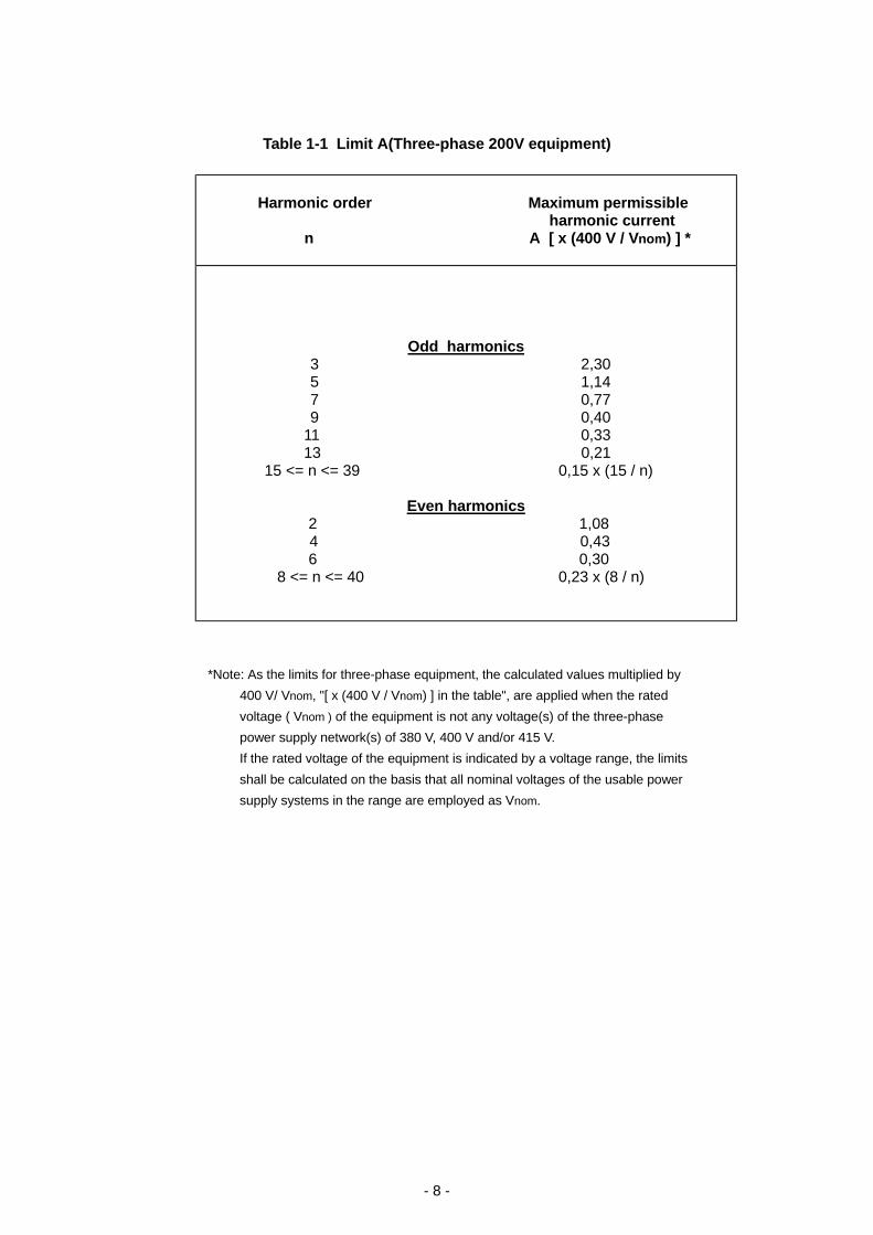
Table 1-1 Limit A(Three-phase 200V equipment)
Harmonic order Maximum permissible
harmonic current n A [ x (400 V / Vnom) ] *
Odd harmonics 3 2,30 5 1,14 7 0,77 9 0,40
11 0,33 13 0,21
15 <= n <= 39 0,15 x (15 / n)
Even harmonics 2 1,08
4 0,43 6 0,30
8 <= n <= 40 0,23 x (8 / n)
*Note: As the limits for three-phase equipment, the calculated values multiplied by 400 V/ Vnom, "[ x (400 V / Vnom) ] in the table", are applied when the rated voltage ( Vnom ) of the equipment is not any voltage(s) of the three-phase power supply network(s) of 380 V, 400 V and/or 415 V. If the rated voltage of the equipment is indicated by a voltage range, the limits shall be calculated on the basis that all nominal voltages of the usable power supply systems in the range are employed as Vnom.
- 9 -
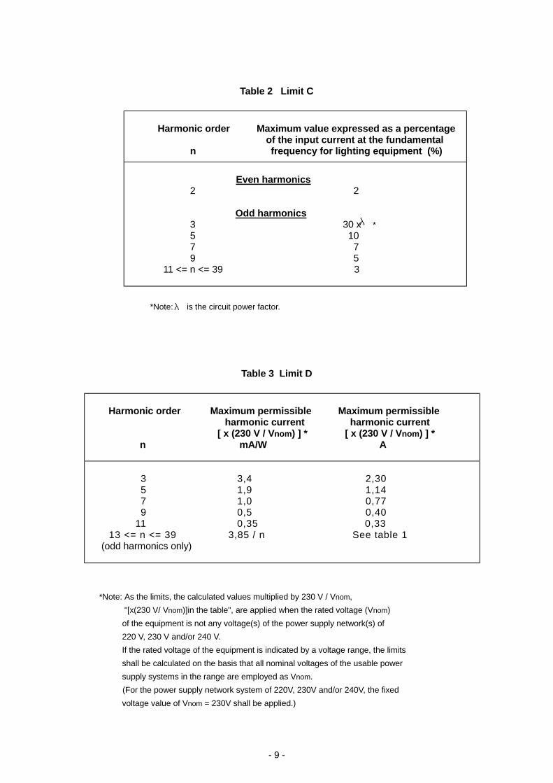
Table 2 Limit C
Harmonic order Maximum value expressed as a percentage
of the input current at the fundamental n frequency for lighting equipment (%)
Even harmonics
2 2
Odd harmonics 3 30 x * 5 10 7 7 9 5
11 <= n <= 39 3
*Note: is the circuit power factor.
Table 3 Limit D
Harmonic order Maximum permissible Maximum permissible
harmonic current harmonic current [ x (230 V / Vnom) ] * [ x (230 V / Vnom) ] * n mA/W A
3 3,4 2,30 5 1,9 1,14 7 1,0 0,77 9 0,5 0,40 11 0,35 0,33 13 <= n <= 39 3,85 / n See table 1
(odd harmonics only)
*Note: As the limits, the calculated values multiplied by 230 V / Vnom, "[x(230 V/ Vnom)]in the table", are applied when the rated voltage (Vnom) of the equipment is not any voltage(s) of the power supply network(s) of 220 V, 230 V and/or 240 V. If the rated voltage of the equipment is indicated by a voltage range, the limits shall be calculated on the basis that all nominal voltages of the usable power supply systems in the range are employed as Vnom. (For the power supply network system of 220V, 230V and/or 240V, the fixed voltage value of Vnom = 230V shall be applied.)
λ
λ
- 10 -
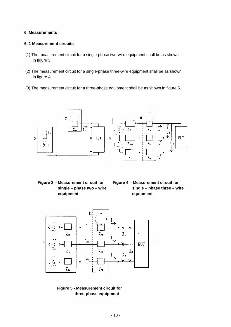
6. Measurements 6. 1 Measurement circuits (1) The measurement circuit for a single-phase two-wire equipment shall be as shown in figure 3. (2) The measurement circuit for a single-phase three-wire equipment shall be as shown in figure 4. (3) The measurement circuit for a three-phase equipment shall be as shown in figure 5.
Figure 3 – Measurement circuit for Figure 4 – Measurement circuit for single – phase two – wire single – phase three – wire equipment equipment
Figure 5 - Measurement circuit for three-phase equipment
- 11 -
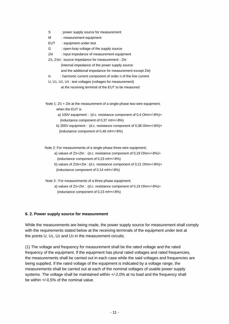
S : power supply source for measurement M : measurement equipment EUT : equipment under test G : open-loop voltage of the supply source ZM : input impedance of measurement equipment ZS, ZSN : source impedance for measurement - ZM
(internal impedance of the power supply source and the additional impedance for measurement except ZM)
In : harmonic current component of order n of the line current U, U1, U2, U3 : test voltages (voltages for measurement)
at the receiving terminal of the EUT to be measured
Note 1: ZS + ZM at the measurement of a single-phase two-wire equipment; when the EUT is
a) 100V equipment : (d.c. resistance component of 0,4 Ohm+/-8%)+ (inductance component of 0,37 mH+/-8%) b) 200V equipment : (d.c. resistance component of 0,38 Ohm+/-8%)+ (inductance component of 0,46 mH+/-8%)
Note 2: For measurements of a single-phase three-wire equipment; a) values of ZS+ZM : (d.c. resistance component of 0,19 Ohm+/-8%)+ (inductance component of 0,23 mH+/-8%) b) values of ZSN+ZM : (d.c. resistance component of 0,21 Ohm+/-8%)+ (inductance component of 0,14 mH+/-8%)
Note 3 : For measurements of a three-phase equipment; a) values of ZS+ZM : (d.c. resistance component of 0,19 Ohm+/-8%)+ (inductance component of 0,23 mH+/-8%) 6. 2. Power supply source for measurement While the measurements are being made, the power supply source for measurement shall comply with the requirements stated below at the receiving terminals of the equipment under test at the points U, U1, U2 and U3 in the measurement circuits. (1) The voltage and frequency for measurement shall be the rated voltage and the rated frequency of the equipment. If the equipment has plural rated voltages and rated frequencies, the measurements shall be carried out in each case while the said voltages and frequencies are being supplied. If the rated voltage of the equipment is indicated by a voltage range, the measurements shall be carried out at each of the nominal voltages of usable power supply systems. The voltage shall be maintained within +/-2,0% at no load and the frequency shall be within +/-0,5% of the nominal value.
- 12 -
(2) The angle between the fundamental voltages on each pair of phases shall be 120 degrees +/-1,5 degrees in the case of the three-phase power supply, and 180 degrees +/-1,5 degrees in the case of the single-phase three-wire power supply. (3) The harmonic voltage ratio included in the power supply source for measurement shall not exceed the values prescribed below at no load and at such condition that a power corresponding to the rated power consumption of the equipment is supplied to a resistance load. 0,9% for harmonic of order 3 0,4% for harmonic of order 5 0,3% for harmonic of order 7 0,2% for harmonic of order 9 0,2% for even harmonics of order from 2 through 10 0,1% for odd harmonics of order from 11 through 39 (4) The peak value of the measurement voltage shall be within 1,40 and 1, 42 times its r. m. s. value at no load and at such condition that a power corresponding to the rated power consumption of the equipment is supplied to a resistance load. The peak value shall be reached within 87 degrees to 93 degrees after the zero-crossing. (5) Care shall be taken to avoid resonance occurring between the internal inductance of the power supply source and the capacitances of the equipment under test. 6. 3 Measurement equipment 6. 3. 1 General requirements The requirements for measurement equipment are stated below. (Informative reference: There is IEC Technical Report 61000-4-7 which is relating with the specifications of the measuring instruments) (1) The type of wave analyzer is not specified. The specifications which will have the approximate equivalence of frequency-domain and time-domain instruments in a practical sense, are shown in the following sub-clauses 6. 3. 2 and 6.3.3. (2) The total error of the measurement equipment including the wave analyzer and the detector (M in figures 3 to 5) when measuring a steady-state harmonic component of the current shall not exceed 5% of the permissible limit values or 0,2% of the rated current of the equipment under test whichever is greater. (3) The input impedance of the whole measurement equipment including the wave analyzer and the detector (M in figures 3 to 5) shall be such that the voltage drop due to the input current of the equipment under test does not exceed 0,15 Vpeak.
- 13 -
(4) If the harmonic components of the measured current vary so as to potentially exceed the limit value during the measurement, they shall be evaluated by a procedure corresponding to a smoothing of the amplitudes according to a first order low pass filter having a time constant of 1,5s +/-10%. If it is difficult to carry out this procedure, such method may be used that the measurements are conducted 4 or more times without carrying out this procedure and the arithmetic mean is obtained. Note 1: When using an external shunt with a time constant not exceeding 10 -5 second, the additional error due to the shunt can be considered to be negligible. Note 2: When using a current-transformer, care shall be taken on the error due to d.c. component of the measured current. Note 3: Care should be taken that the possible high crest factor (ratio of peak value to r.m.s. value) of the current or the high value of the fundamental current (supply frequency), as compared to the harmonic currents to be measured, do not produce overload or harmful intermodulation error signals in the input stages of the instruments. 6. 3. 2 Requirements for frequency-domain instrumentation (1) Requirements if the equipment under test produces only steady-state harmonics; (a) As for the attenuation representing the selectivity of the instrument, the minimum attenuations at frequencies fn-f1 and fn+f1, for each value of fn being the frequency of the harmonic of order n to be measured (for which the instrument is set), shall be defined by the following values. If 2f1 <= fn<= 12f1 : 30 dB If 12f1< fn<= 20f1 : 20 dB If 20f1< fn<= 40f1 : 15 dB (b) The attenuation shall be higher than or equal to 50 dB for any injected single harmonic frequency equal or lower than 0,5fn. (c) The attenuation of the supply frequency f1 (50 or 60 Hz) shall be at least 60 dB. (2) Additional requirements for all other cases including fluctuating harmonics; If the harmonic components of the input current of the equipment under test show fast fluctuations during the test, it is necessary, in addition to consider the following, when the measuring instrument is set for the frequency fn of the harmonic to be measured. (a) It is allowed to use instrumentation with a bandwidth in the range 3 Hz to 10 Hz keeping in mind that a larger bandwidth can give higher measured values. (b) In case of doubt, where the limits are exceeded, an instrument shall be used with a bandwidth of 3 Hz +/-0,5 Hz between point at -3 dB and with a minimum attenuation of 25 dB for a single frequency signal at a frequency equal to (fn -15)Hz or (fn +15)Hz.
- 14 -
Note : Selective wave analyzers usually have a much lower time constant than specified
above Sub-clause 6.3.1(4). The required time constant of 1,5 seconds for harmonic emission measurements may then be best achieved by the insertion of a low-pass filter just ahead of the indicator or recorder. 6. 3. 3 Requirements for time-domain instrumentation using Discrete-Fourier-Transform
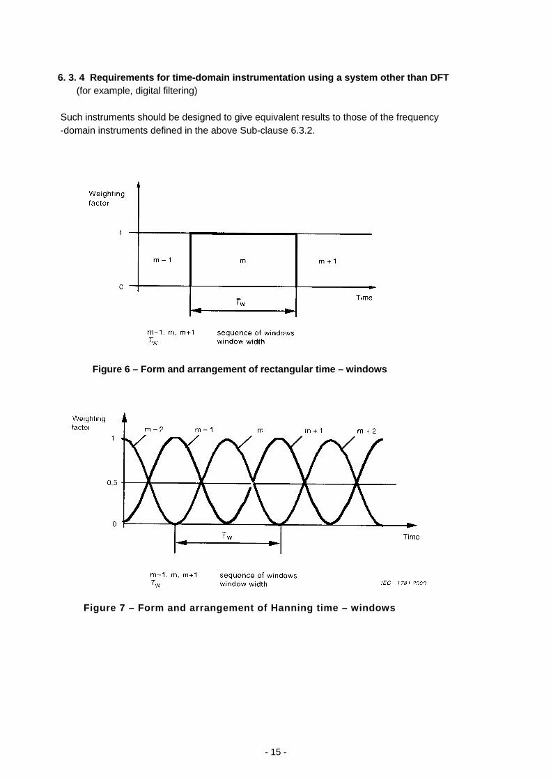
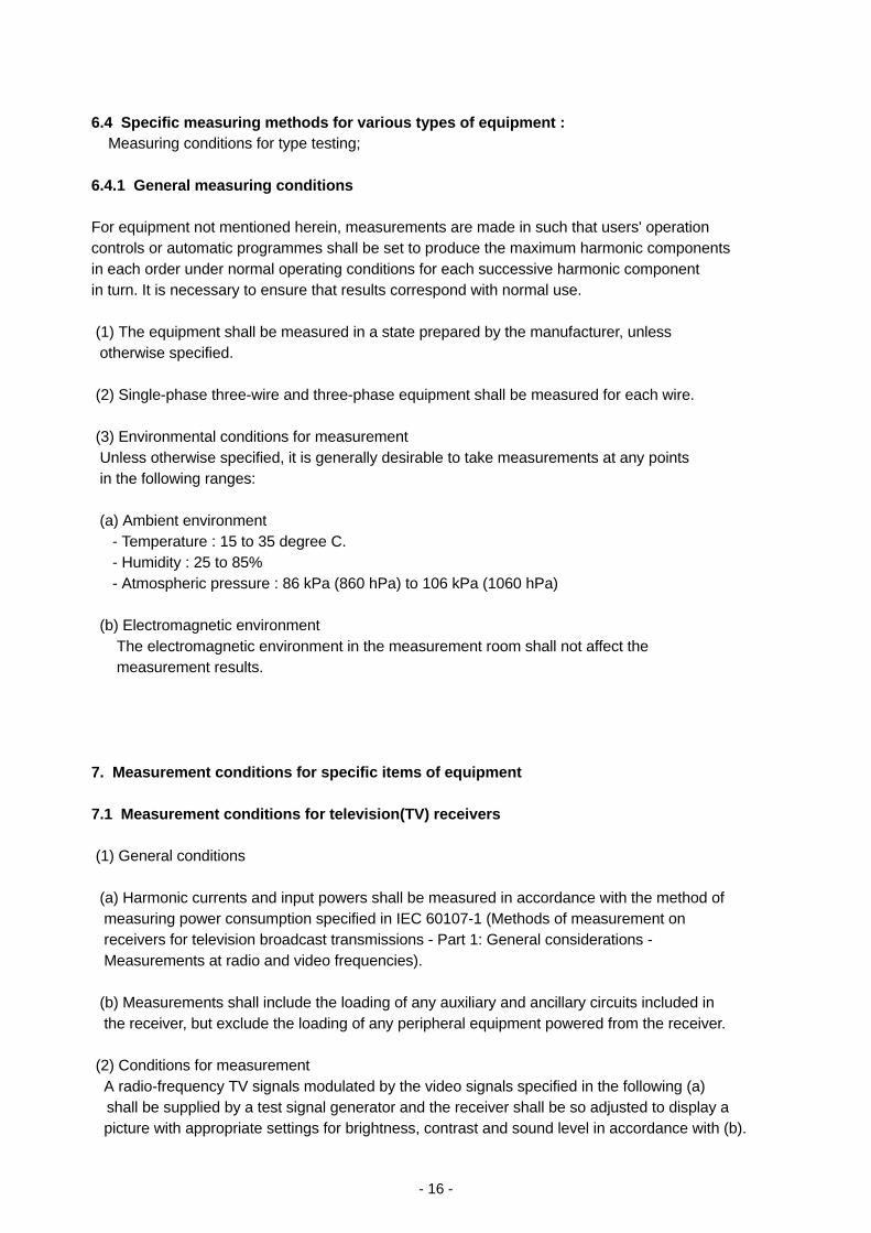
(DFT) (1) Requirements if the equipment under test produces only steady-state harmonics; (a) The width of the measuring window shall be between 4 and 30 cycles of the fundamental frequency. (b) The shape of the window is not specified. However, if a rectangular window is used, it is necessary to synchronize the sampling rate with the fundamental frequency f1, in such a way that the maximum relative deviation between the fundamental frequency f1 and frequency fsyn to which the sampling rate is synchronized, is equal to or lower than 0,03% of f1 under steady-state conditions. When using a Hanning Window, such a strict synchronization may not be necessary. (c) There are no requirements for the gap and/or overlapping between successive windows. (d) Attenuation of anti-aliasing filters shall be at least 50 dB for frequencies folded back into the measured frequency-band. (2) Additional requirements for all other cases including fluctuating harmonics; (a) There shall be no gap, and no overlapping between successive windows for rectangular (uniform) windows. (figure 6) There shall be a 50% overlap and no gap for Hanning type windows. (figure 7) Other types of windows shall not be used. (b) In case of doubt, where the limits are exceeded, an instrument shall be used which has a window width of 16 cycles of the fundamental frequency for a rectangular window or of 20 to 25 cycles of the fundamental frequency for a Hanning window. Note: A characteristic equivalent to an analogue time constant of 1,5 seconds stated
in the above Sub-clause 6.3.1(4), may be achieved by real-time software handling of the successive window measurements. If it is difficult to carry out this procedure,
such method may be used that the measurements are conducted 4 or more times without carrying out this procedure and the arithmetic mean is obtained.
- 15 -
6. 3. 4 Requirements for time-domain instrumentation using a system other than DFT (for example, digital filtering) Such instruments should be designed to give equivalent results to those of the frequency -domain instruments defined in the above Sub-clause 6.3.2.
Figure 6 – Form and arrangement of rectangular time – windows
Figure 7 – Form and arrangement of Hanning time – windows
- 16 -
6.4 Specific measuring methods for various types of equipment : Measuring conditions for type testing; 6.4.1 General measuring conditions For equipment not mentioned herein, measurements are made in such that users' operation controls or automatic programmes shall be set to produce the maximum harmonic components in each order under normal operating conditions for each successive harmonic component in turn. It is necessary to ensure that results correspond with normal use. (1) The equipment shall be measured in a state prepared by the manufacturer, unless otherwise specified. (2) Single-phase three-wire and three-phase equipment shall be measured for each wire. (3) Environmental conditions for measurement Unless otherwise specified, it is generally desirable to take measurements at any points in the following ranges: (a) Ambient environment - Temperature : 15 to 35 degree C. - Humidity : 25 to 85% - Atmospheric pressure : 86 kPa (860 hPa) to 106 kPa (1060 hPa) (b) Electromagnetic environment The electromagnetic environment in the measurement room shall not affect the measurement results. 7. Measurement conditions for specific items of equipment 7.1 Measurement conditions for television(TV) receivers (1) General conditions (a) Harmonic currents and input powers shall be measured in accordance with the method of measuring power consumption specified in IEC 60107-1 (Methods of measurement on receivers for television broadcast transmissions - Part 1: General considerations - Measurements at radio and video frequencies). (b) Measurements shall include the loading of any auxiliary and ancillary circuits included in the receiver, but exclude the loading of any peripheral equipment powered from the receiver. (2) Conditions for measurement A radio-frequency TV signals modulated by the video signals specified in the following (a)
shall be supplied by a test signal generator and the receiver shall be so adjusted to display a picture with appropriate settings for brightness, contrast and sound level in accordance with (b).
- 17 -
(a) The TV receiver is fed by an r.f. regular TV signal with a level of 70 dB(µV) across 75 ohms and the following test modulations.
Note: For equipment that operates only on base-band signals, a composite signal with 1 Vp-p is supplied as the video signal input.
- Sound modulation: 100% - Sound signal: 1 kHz, sine wave - Video signal: A colour bar signal which is of the colour sequence (75/0/75/0) according
to ITU-R Recommendation 471-1 and which contains a white window. [Supplementary information: The composite colour bar signal specified in sub-clause 2. (8)(u)of JIS C 6101(1988)(Measuring methods of receivers for television broadcast transmissions.) Presently, JIS C 6101-1 (Methods of measurement on receivers for television broadcast transmissions - Part 1: General considerations - Measurements at radio and video frequencies).] (b) The contrast and brightness shall be so adjusted that the luminance will reach a specified level such that the white reference level corresponds to 150 cd/m2 and the black level to 2 cd/m2 in a three-vertical-striped signal. If the luminance does not reach the specified level at that time, the controls shall be set to the reference position as factory-configured.
The sound level is set in such a manner that one-eighth of rated sound output power is obtained, measured at the loudspeaker terminals, at a frequency of 1000 Hz. In the case of stereophonic equipment, this output shall be present at both outputs. 7.2 Measurement conditions for audio amplifiers Audio amplifiers which draw a supply current which varies by less than 15 % of the maximum current with input signals between no signal and rated source e.m.f. (as defined in IEC 60268-3) shall be tested with no input signal. Other audio amplifiers shall be measured under the following conditions: - user controls (in particular, any controls affecting the frequency response)shall be set to give the widest flat response achievable; - input signals and load conditions as given in sub-clause 4.2.6 b) of [Revision 2 (including Revision 1) of the fifth edition of] IEC 60065.
However, if no major difference occurs in the measurement results, 1000 Hz sine wave signal may be used instead of the standard signals specified in sub-clause 4.1.5. If equipment operates in a specific frequency band and it is inappropriate to use 1000 Hz sine wave signal, any other signal of sine wave with other frequency than 1000 Hz at which the equipment shows the maximum response may be used. In these cases, the type of the signal used in the measurement shall be recorded in the measurement results.
- 18 -
Note 1: In harmonic current measurements, the transient phenomena that may occur in a
switch-over or similar operation are disregarded and the measured values which are obtained during the steady state operation of equipment shall be adopted. Note 2: In the case of system equipment, measurements shall be made under the operation
of the combination of the parts including any contained equipment and/or functions which are power supplies and which have the maximum power consumption in the actually used combination. The composition of the combinations in the system equipment used for measurement shall be recorded together with the measurement results. 7.3 Measurement conditions for video-cassette recorders (1) Measurements shall be made in the playback mode with the standard tape speed, using the tape recorded by the same or equivalent video and sound signals used for the television receiver measurements. (2) The tape used for measurements shall conform to the format requirement and shall be around the beginning part of the winding-up. 7.4 Measurement conditions for video disk players/recorders Measurements shall be made in the maximum load condition under the playback mode with the standard speed. 7.5 Measurement conditions for lighting equipment (1) General conditions
Measurements shall be made in a ventilated atmosphere and at an ambient temperature of 25 +/-5 degree C. (2) Lamp(s) Lamp(s) used for the measurements of the luminaires and similar equipment shall be ones which conform to the reference lamp(s) in JIS C8105 or the equivalent. They shall be aged for at least the period prescribed in the relevant JIS standard. They shall be operated for at least 15 min before a series of measurements is made. During ageing and measurement, lamp(s) shall be installed as in normal use. NOTE: Some lamp types may require a stabilizing period exceeding 15 min.
Information given in the relevant lamp specification must be observed.
- 19 -
(3) Luminaires The luminaire is measured as manufactured. When the luminaire incorporates more than one
lamp, all lamps are connected and operated during the measurements. When the luminaire is marked as applicable use with more than one type of lamp, measurements shall be made with the lamp which has the maximum power in the types marked on the name plate or the like of the luminaires. In the case where the luminaire is equipped with a glow starter, a starter in accordance with JIS C7603 (Glow Starters for Fluorescent Lamps) shall be used. Incandescent lamp luminaires which do not incorporate an electronic transformer or a dimming device and luminaires which use self-ballasted lamps complying with this Guideline are deemed to fulfil the harmonic current requirements and need not be measured. Luminaires containing a ballast or an electronic transformer that is defined as compliance with the requirements are deemed to fulfil the harmonic current requirements and need not be measured. If these components are not yet known as conformed, the luminaires themselves which contain the components shall be measured and shall comply with the requirements. The harmonic currents of luminaires equipped with a dimming device shall be measured at the maximum load and at each dimming level specified by the manufacturer. However, if the dimming level can be set consecutively, it shall be set to the dimming level where the input power gets the centre between the maximum and the minimum. 7.6 Measurement conditions for independent dimmers Independent dimmers shall be measured with in principle the load of incandescent lamps and being equipped with the permissible maximum load of the dimmers. These dimmers shall be set to a firing angle of 90+/-5 degrees. 7.7 Measurement conditions for vacuum cleaners The vacuum cleaner shall be measured under the continuous operation with the air inlet hose, the tip of which is left open without the extension pipe or the nozzle, and with the empty dust container or paper filter. If vacuum cleaners have a control of power consumption, the control shall be set to a firing angle of 90 +/-5 degrees, or if controlled by steps, to that step closest to 90 degrees. In the case of vacuum cleaners without any control of power consumption, measurements shall be made in the operation under the same conditions as ones for the measurement of the rated power consumption. Before measurements, the vacuum cleaner shall be aged in a standard measuring condition until the temperatures of the components attain stable.
- 20 -
7.8 Measurement conditions for washing machines The washing machine shall be measured under the normal washing condition. It is filled with
a piece of cotton cloth, size 70 cm x 70 cm, dry weight from 140 g/cm2 to 175 g/cm2, as a load
for measurement. Normally, it is sufficient to measure the harmonics during the last stage, rinsing. In case of doubt, the measurement shall be made in a full programme of the washing process. Transient harmonics are measured during a very short time for speed-up operations after the start-up of the reversing rotation. 7.9 Measurement conditions for microwave ovens The microwave oven shall be measured during the operation in the rated high-frequency output. It is operated with a potable water load of initially 1000 g +/- 50 g in a cylindrical borosilicate glass vessel, having a maximum material thickness of 3 mm and an outside diameter of approximately 190 mm. The load is placed at the centre of the shelf. 7.10 Measurement conditions for electromagnetic cookers (induction hobs) Electromagnetic cookers are operated and measured with an enamelled steel pan which contains approximately half its capacity of water at room temperature, and positioned at the centre of each cooking zone. Thermal controls are adjusted to their highest setting. (1) The diameter of the base of the pan used is to be at least the diameter of the cooking zone. (2) The maximum concavity of the base of the pan is 3D/1000 where D is the diameter of the flat
area of the base of the pan. (3) The base of the pan is not to be convex. The concavity is checked using an empty pan. 7.11 Measurement conditions for air conditioners The air conditioner is measured after the operation becomes steady-state under the following conditions : (1) The temperature control shall be set to the lowest value in the cooling mode and to the highest value in the heating mode. (2) The ambient temperature for measurement shall be 30 +/-5 degree C in the cooling mode, and 15 +/-5 degree C for the heating mode. The ambient temperature is defined as the temperature of the air inhaled from the indoor unit.
- 21 -
Current
7.12 Measurement conditions for information technology equipment (ITE) The ITE shall in principle be measured under the rated input power condition of the equipment. In this case, the equipment, if necessary, may be configured with the following methods to simulate the rated input power condition. (1) It is measured with additional load(s) to get the rated input power condition. (2) It is measured in such a way that the rated input power condition is actualized by its power supply unit itself for the equipment. 7.12.1 Measurement conditions for copying machine and similar equipment (1) It shall be measured when it is continuously copying the original with its maximum active
input power. At the same time, all installable accessories shall be installed and operating if possible in a general way.
(2) The original shall be the "A4-size test chart" specified in JIS B9523 or B9524. Additional Note for English version: JIS B9523/B9524 is test chart for monochrome/full-colour document.
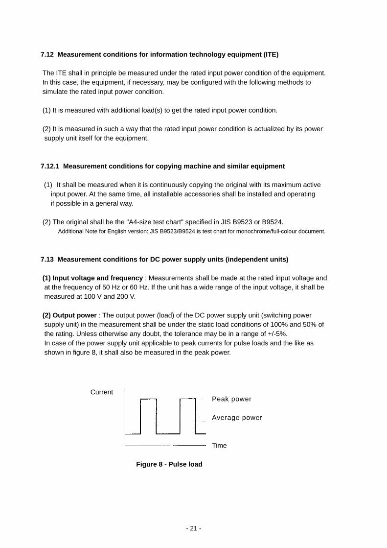
7.13 Measurement conditions for DC power supply units (independent units) (1) Input voltage and frequency : Measurements shall be made at the rated input voltage and at the frequency of 50 Hz or 60 Hz. If the unit has a wide range of the input voltage, it shaIl be measured at 100 V and 200 V. (2) Output power : The output power (load) of the DC power supply unit (switching power supply unit) in the measurement shall be under the static load conditions of 100% and 50% of the rating. Unless otherwise any doubt, the tolerance may be in a range of +/-5%. In case of the power supply unit applicable to peak currents for pulse loads and the like as shown in figure 8, it shall also be measured in the peak power. Peak power Average power Time
Figure 8 - Pulse load
- 22 -
(3) Ageing time : Measurements should desirably be made under the condition where the efficiency and the like change little after the switching power supply was sufficiently aged. The aging time for measurements is decided to be 30 minutes after turn-on of the power, however, if there is no doubt about the measurement values, the measurements may be made after more than one minute have passed. (4) Averaging : In the case of equipment where instantaneous current values fluctuate in short cycles even in a steady state, the average value of the measurements of eight times shall be adopted. 7.14 Measurement conditions for motor-driven tools (1) Tools without any electronic speed control Measurements shall be made in the input power responding to the rated load at the rated voltage. (2) Tools equipped with electronic speed control Measurements shall be made in such conditions that the tool is set to a firing angle of 90 +/-5 degrees at the rated voltage and that the load current is set to the centre value between the rated current and no load current. 7.15 Measurement conditions for others Measurement conditions for other types of equipment are added upon request.
[Supplementary Requirements] 1. Limits for Class A equipment Air-conditioners, computers, general-purpose inverters and servo amplifiers which have the active input power of more than 600W shall be subject to the limits given in table 1A until December 31, 2003 as the tentative deadline date. In case of three-phase 200 V equipment, the limits given in table 1-1A shall be applied until the same tentative deadline date. The requirements of these limits shall then be reviewed when the tentative deadline is due.
- 23 -
2. Limits for Class C equipment Harmonic currents for lighting equipment used in households having a "special wave shape" as illustrated in figure 1 shall conform to Limit D given in table 3 until January 1, 1998. 3. Limits for Class D equipment No limits shall be applied to the equipment having an active input power of 75 W or less, except for lighting equipment, until December 31, 2003 as the tentative deadline date. However, in the case that its application of no limits is recognized as a serious effect on the harmonics problems, the tentative date will be terminated at the time even in the period before the deadline date.
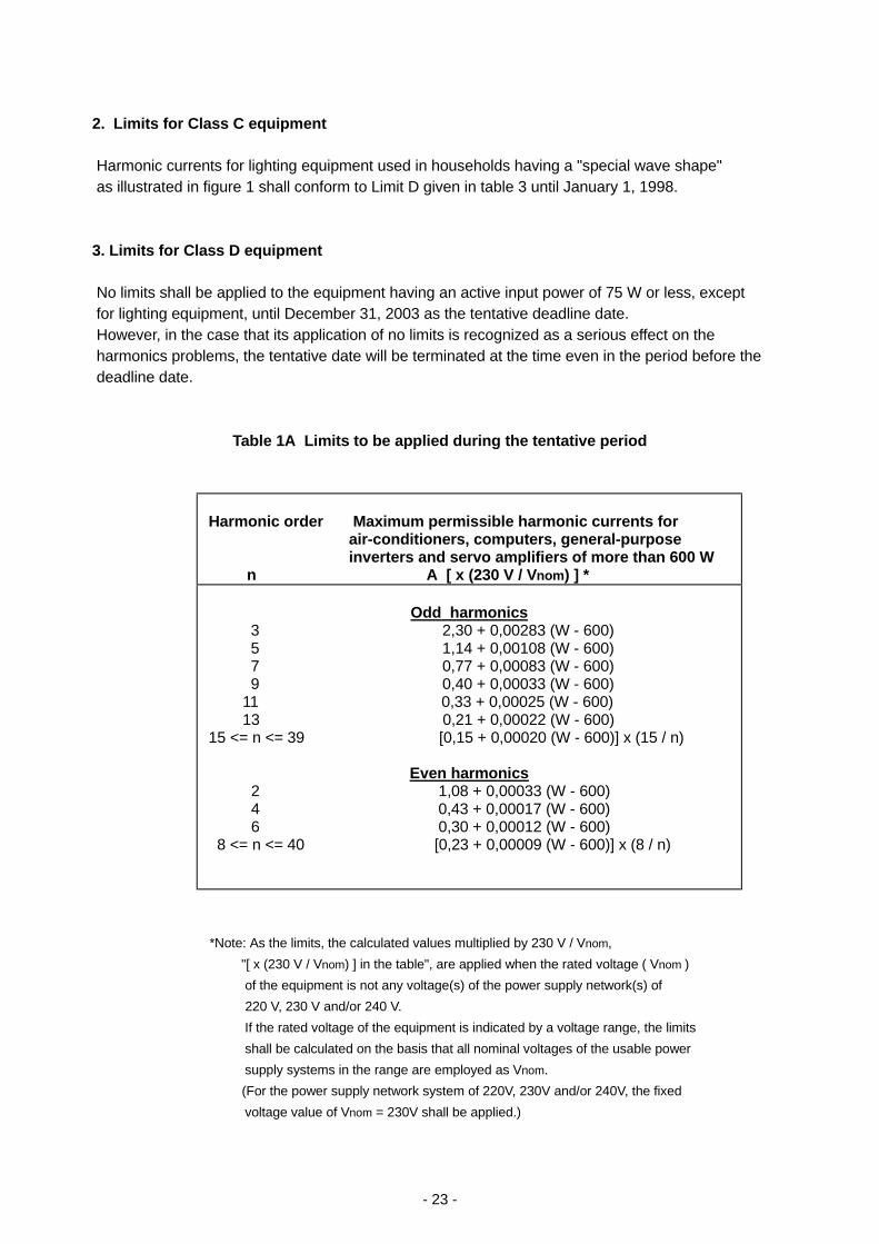
Table 1A Limits to be applied during the tentative period
Harmonic order Maximum permissible harmonic currents for air-conditioners, computers, general-purpose inverters and servo amplifiers of more than 600 W n A [ x (230 V / Vnom) ] *
Odd harmonics
3 2,30 + 0,00283 (W - 600) 5 1,14 + 0,00108 (W - 600) 7 0,77 + 0,00083 (W - 600) 9 0,40 + 0,00033 (W - 600)
11 0,33 + 0,00025 (W - 600) 13 0,21 + 0,00022 (W - 600) 15 <= n <= 39 [0,15 + 0,00020 (W - 600)] x (15 / n)
Even harmonics 2 1,08 + 0,00033 (W - 600) 4 0,43 + 0,00017 (W - 600) 6 0,30 + 0,00012 (W - 600) 8 <= n <= 40 [0,23 + 0,00009 (W - 600)] x (8 / n)
*Note: As the limits, the calculated values multiplied by 230 V / Vnom, "[ x (230 V / Vnom) ] in the table", are applied when the rated voltage ( Vnom ) of the equipment is not any voltage(s) of the power supply network(s) of 220 V, 230 V and/or 240 V. If the rated voltage of the equipment is indicated by a voltage range, the limits shall be calculated on the basis that all nominal voltages of the usable power supply systems in the range are employed as Vnom. (For the power supply network system of 220V, 230V and/or 240V, the fixed voltage value of Vnom = 230V shall be applied.)
- 24 -
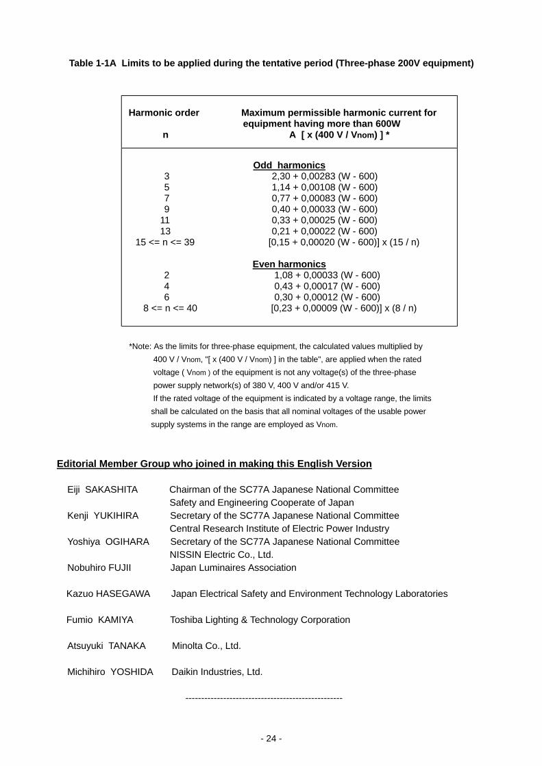
Table 1-1A Limits to be applied during the tentative period (Three-phase 200V equipment)
Harmonic order Maximum permissible harmonic current for
equipment having more than 600W n A [ x (400 V / Vnom) ] *
Odd harmonics
3 2,30 + 0,00283 (W - 600) 5 1,14 + 0,00108 (W - 600) 7 0,77 + 0,00083 (W - 600) 9 0,40 + 0,00033 (W - 600)
11 0,33 + 0,00025 (W - 600) 13 0,21 + 0,00022 (W - 600)
15 <= n <= 39 [0,15 + 0,00020 (W - 600)] x (15 / n)
Even harmonics 2 1,08 + 0,00033 (W - 600) 4 0,43 + 0,00017 (W - 600) 6 0,30 + 0,00012 (W - 600)
8 <= n <= 40 [0,23 + 0,00009 (W - 600)] x (8 / n)
*Note: As the limits for three-phase equipment, the calculated values multiplied by
400 V / Vnom, "[ x (400 V / Vnom) ] in the table", are applied when the rated voltage ( Vnom ) of the equipment is not any voltage(s) of the three-phase power supply network(s) of 380 V, 400 V and/or 415 V. If the rated voltage of the equipment is indicated by a voltage range, the limits shall be calculated on the basis that all nominal voltages of the usable power supply systems in the range are employed as Vnom. Editorial Member Group who joined in making this English Version Eiji SAKASHITA Chairman of the SC77A Japanese National Committee Safety and Engineering Cooperate of Japan Kenji YUKIHIRA Secretary of the SC77A Japanese National Committee Central Research Institute of Electric Power Industry Yoshiya OGIHARA Secretary of the SC77A Japanese National Committee NISSIN Electric Co., Ltd. Nobuhiro FUJII Japan Luminaires Association
Kazuo HASEGAWA Japan Electrical Safety and Environment Technology Laboratories Fumio KAMIYA Toshiba Lighting & Technology Corporation
Atsuyuki TANAKA Minolta Co., Ltd. Michihiro YOSHIDA Daikin Industries, Ltd. --------------------------------------------------