Japanese and World Technology Evaluation Centers JTEC WTEClew/PUBLICATION PDFs/RP/JTEC 1997.pdf ·...
166
Japanese and World Technology Evaluation Centers JTEC WTEC JTEC/WTEC Panel Report on Rapid Prototyping in Europe and Japan VOLUME I. ANALYTICAL CHAPTERS Friedrich B. Prinz (Panel Chair) Clinton L. Atwood Richard F. Aubin Joseph J. Beaman Robert L. Brown Paul S. Fussell Allan J. Lightman Emanuel Sachs Lee E. Weiss Michael J. Wozny March 1997 Published and Distributed by Rapid Prototyping Association of the Society of Manufacturing Engineers in cooperation with International Technology Research Institute R.D. Shelton, Director Geoffrey M. Holdridge, WTEC Director Loyola College in Maryland 4501 North Charles Street Baltimore, Maryland 21210-2699
Transcript of Japanese and World Technology Evaluation Centers JTEC WTEClew/PUBLICATION PDFs/RP/JTEC 1997.pdf ·...

Japanese and World Technology Evaluation Centers
JTECWTEC
JTEC/WTEC Panel Report on
Rapid Prototyping in Europe and Japan
VOLUME I. ANALYTICAL CHAPTERS
Friedrich B. Prinz (Panel Chair)Clinton L. AtwoodRichard F. AubinJoseph J. BeamanRobert L. BrownPaul S. FussellAllan J. LightmanEmanuel SachsLee E. WeissMichael J. Wozny
March 1997
Published and Distributed byRapid Prototyping Association of the Society of Manufacturing Engineers
in cooperation with
International Technology Research InstituteR.D. Shelton, Director
Geoffrey M. Holdridge, WTEC Director
Loyola College in Maryland4501 North Charles Street
Baltimore, Maryland 21210-2699

JTEC/WTEC PANEL ON RAPID PROTOTYPINGIN EUROPE AND JAPAN
Sponsored by the National Science Foundation, the Department of Energy, the Defense Advanced Research ProjectsAgency, the Office of Naval Research, and the Department of Commerce of the United States Government.
Friedrich B. Prinz (Panel Chair)Stanford UniversityTerman 501Stanford, CA 94305-4021
Clinton L. AtwoodSandia National LaboratoriesP.O. Box 5800 M/S 0958Albuquerque, NM 87185
Richard F. AubinUnited Technologies ResearchCenter411 Silver Lane, MS 129-48East Hartford, CT 06108
Joseph J. BeamanUniversity of Texas at AustinETC 5.134CCampus Mail Code: C2200Austin, TX 78712
Robert L. BrownGillette CompanyPrudential Tower Bldg., 49th FloorBoston, MA 02199
Paul S. FussellAlcoa Technical Center100 Technical DriveAlcoa Center, PA 15069-0001
Allan J. LightmanUniversity of Dayton ResearchInstitute300 College ParkDayton, OH 45469-0150
Emanuel SachsMITRoom 35-13677 Massachusetts Ave.Cambridge, MA 02139
Lee E. WeissCarnegie Mellon University217 Smith HallPittsburgh, PA 15213
Michael J. WoznyRensselaer Polytechnic InstituteCenter for Advanced TechnologyCII 8015Troy, NY 12180-3590
INTERNATIONAL TECHNOLOGY RESEARCH INSTITUTEWTEC PROGRAM
The World Technology Evaluation Center (WTEC) at Loyola College (previously known as the JapaneseTechnology Evaluation Center, JTEC) provides assessments of foreign research and development in selectedtechnologies under a cooperative agreement with the National Science Foundation (NSF). Loyola's InternationalTechnology Research Institute (ITRI), R.D. Shelton, Director, is the umbrella organization for WTEC. Paul Herer,Senior Advisor for Planning and Technology Evaluation at NSF's Engineering Directorate, is NSF Program Directorfor WTEC. Other U.S. government agencies that provide support for the program include the National Aeronauticsand Space Administration, the Department of Energy, the Department of Commerce, and the Department of Defense.
WTEC's mission is to inform U.S. policy makers, strategic planners, and managers of the state of selectedtechnologies in foreign countries in comparison to the United States. WTEC assessments cover basic research,advanced development, and applications/commercialization. Small panels of about six technical experts conductWTEC assessments. Panelists are leading authorities in their field, technically active, and knowledgeable aboutU.S. and foreign research programs. As part of the assessment process, panels visit and carry out extensivediscussions with foreign scientists and engineers in universities and in industry/government labs.
The ITRI staff at Loyola College help select topics, recruit expert panelists, arrange study visits to foreignlaboratories, organize workshop presentations, and finally, edit and disseminate the final reports.
Dr. R.D. Shelton Mr. Geoff Holdridge Dr. George GamotaPrincipal Investigator WTEC Director Co-Principal InvestigatorLoyola College Loyola College 17 Solomon Pierce RoadBaltimore, MD 21210 Baltimore, MD 21210 Lexington, MA 02173

JTEC/WTEC Panel on
RAPID PROTOTYPING IN EUROPE AND JAPAN
FINAL REPORT
VOLUME I. ANALYTICAL CHAPTERS
March 1997
Friedrich B. Prinz, Panel ChairClinton L. AtwoodRichard F. AubinJoseph J. BeamanRobert L. BrownPaul S. FussellAllan J. LightmanEmanuel SachsLee E. WeissMichael J. Wozny
ISBN 1-883712-44-0This document was sponsored by the National Science Foundation (NSF), the Department of Energy, theDefense Advanced Research Projects Agency, the Office of Naval Research (ONR), and the Department ofCommerce of the United States Government under NSF Cooperative Agreement ENG-9416970 and ONRGrant N00014-95-1-1220, awarded to the International Technology Research Institute at Loyola College inMaryland. The Government has certain rights in this material. Any opinions, findings, and conclusions orrecommendations expressed in this material are those of the authors and do not necessarily reflect the viewsof the United States Government, the authors’ parent institutions, or Loyola College.

In Memory of Richard S. Aubin1948 - 1997
It was with great sadness that members of the JTEC/WTEC rapid prototyping panel learned of the death offellow panelist Dick Aubin. The panel would like to take this opportunity to recognize Dick’s lastingcontributions to not only the effort of this study, but to the rapid prototyping community at large.
Dick graduated from of the University of Hartford and was employed at Pratt & Whitney (UnitedTechnologies, UT) for many years. He led numerous partnership efforts among industry, universities andgovernment. He served as the chairman of the Rapid Prototyping Association of the Society ofManufacturing Engineers and chaired the National Science Foundation’s Rapid Mold Tooling Consortia, aventure of MIT, UT and other Fortune 500 companies. He was a pioneer in the International IntelligentManufacturing Systems (IMS) effort with his work in the Rapid Product Development feasibility study. Heleaves an internationally acclaimed reputation for his knowledge and leadership in these advancedmanufacturing technologies. At the time of his death he was Manager of Rapid Manufacturing, UnitedTechnologies Research Center.
Dick Lopatka, one of Dick’s colleagues at United Technologies, speaks for all of us in saying, "Dick will begreatly missed not only due to his technology leadership, but for his energy, humor, generosity and concernfor others."
It was an honor to have Dick as a member of this panel. He was an innovative leader, an outstanding educatorin the field of rapid prototyping, and an inspiration to those whose lives he touched. He will be missed by allwho knew him.
Fritz B. PrinzPanel Chair
International Technology Research Institute (ITRI)World Technology Evaluation Center (WTEC)
R. D. Shelton, Principal Investigator, ITRI DirectorGeorge Gamota, Co-Principal Investigator, TTEC Director
Geoffrey M. Holdridge, WTEC DirectorBobby A. Williams, WTEC Deputy DirectorCatrina M. Foley, Administrative Assistant
Aminah Batta, Editorial AssistantRoan E. Horning, Professional Assistant
Jason Ruggieri, Student StaffMichael Stone, Student Staff
Patricia M. H. Johnson, Editor
Sylvia Walters of Stanford University, Rapid Prototyping Study CoordinatorCecil Uyehara, Senior Advisor for Japan Operations
Hiroshi Morishita, Consultant, Japan Operations
Copyright 1997 (printed version) by the Society of Manufacturing Engineers. Loyola College in Maryland holdscopyright to electronic forms of this report. This work relates to Department of Navy Grant N00014-95-1-1220 issued bythe Office of Naval Research and NSF Cooperative Agreement ENG-9416970. The United States Government retains anonexclusive and nontransferable license to exercise all exclusive rights provided by copyright. The ISBN number forthis report is 1-882712-44-0. Volume II, Site Reports, is available separately from the National Technical InformationService (NTIS) as PB96-199583. A list of available JTEC/WTEC reports and information on ordering them from NTISis included on the inside back cover of this report.

i
FOREWORD
The National Science Foundation (NSF) has been involved in funding technology assessments comparing theUnited States and foreign countries since 1983. A sizable proportion of this activity has been in the JapaneseTechnology Evaluation Center (JTEC) and World Technology Evaluation Center (WTEC) programs. NSFhas supported more than 40 JTEC and WTEC studies over a wide range of technical topics. Both programsare now subsumed under the single name, WTEC, although the JTEC name still appears in some reports thatcover only Japan.
As U.S. scientific and technological leadership is challenged in areas of previous dominance such asaeronautics, space, and nuclear power, many governmental and private organizations seek to set policies thatwill help maintain U.S. strengths. To do this effectively requires an understanding of the relative position ofthe United States and other countries. The purpose of the WTEC program is to assess research anddevelopment efforts in other countries in specific areas of technology, to compare these efforts and theirresults to U.S. research in the same areas, and to identify opportunities for international collaboration inprecompetitive research.
Many U.S. organizations support substantial data gathering and analysis efforts directed at nations such asJapan. But often the results of these studies are not widely available. At the same time, government andprivately sponsored studies that are in the public domain tend to be "input" studies; that is, they provideenumeration of inputs to the research and development process, such as monetary expenditures, personneldata, and facilities, but do not provide an assessment of the quality or quantity of the outputs obtained.
Studies of the outputs of the research and development process are more difficult to perform because theyrequire a subjective analysis performed by individuals who are experts in the relevant technical fields. TheNSF staff includes professionals with expertise in a wide range of disciplines. These individuals provide thetechnical expertise needed to assemble panels of experts who can perform competent, unbiased, technicalreviews of research and development activities.
Specific technologies, such as telecommunications, biotechnology, microelectromechanical systems, andadvanced materials, are selected for study by government agencies that have an interest in obtaining theresults of an assessment and are able to contribute to its funding. A typical assessment is sponsored by two tofour agencies. In the first few years of the program, most of the studies focused on Japan, reflecting concernover Japan’s growing economic prowess.
Beginning in 1990, we began to broaden the geographic focus of the studies. As interest in the EuropeanCommunity (now the European Union) grew, we added Europe as an area of study. With the breakup of theformer Soviet Union, we began organizing visits to previously restricted research sites opening up there.These most recent WTEC studies have focused on identifying opportunities for cooperation with researchersand institutes in Russia, the Ukraine, and Belarus, rather than on assessing them from a competitiveviewpoint. Most recently, studies have begun to focus also on emerging technological powers in Asia.
In the past several years, we also have begun to substantially expand our efforts to disseminate information.Attendance at WTEC workshops (in which panels present preliminary findings) has increased, especiallyindustry participation. Representatives of U.S. industry now routinely number 50% or more of the totalattendance, with a broad cross-section of government and academic representatives making up the remainder.Publications by JTEC and WTEC panel members based on our studies have increased, as have the number ofpresentations by panelists at professional society meetings.
The WTEC program will continue to evolve in response to changing conditions in the years to come. We arenow implementing initiatives aimed at the following objectives:
• Disseminating the results of WTEC studies via the Internet. Fourteen of the most recent WTEC finalreports are now available on the World Wide Web (http://itri.loyola.edu) or via anonymous FTP(ftp.wtec.loyola.edu/pub/). Viewgraphs from several recent workshops are also on the Web server.

ii
• Expanding opportunities for the larger science and technology community to help define and organizestudies
• Increasing industry sponsorship of JTEC and WTEC studies
The latter two objectives are now being served under the recently inaugurated WTEC Community-InitiatedState-of-the-Art Reviews (CISAR) initiative. CISAR provides an opportunity for the U.S. R&D communityto suggest and carry out studies that might not otherwise be funded solely at the initiative of the government.For example, WTEC has formed partnerships with university/industry teams, with partial funding fromindustry, to carry out three CISAR studies, covering the Korean semiconductor industry, electronics finalassembly technologies in Pacific Rim countries, and civil infrastructure technologies in Pacific Rim countries,respectively. Several other topics are under consideration. Further information on the CISAR initiative isavailable on the WTEC WWW server (http://itri.loyola.edu/cisar.htm) or by contacting the WTEC office.
In the end, all government-funded programs must answer the question, How has this investment benefited thenation? A few of the benefits of the WTEC program follow:
• JTEC studies have contributed significantly to U.S. benchmarking of the growing prowess of Japan’stechnological enterprise. Some have estimated that JTEC has been responsible for over half the majorJapanese technology benchmarking studies conducted in the United States in the past decade. JTECreports have also been widely cited in various competitiveness studies.
• These studies have provided important input to policy makers in federal mission agencies. JTEC andWTEC panel chairs have given special briefings to senior officials of the Department of Energy andCommerce, to the National Aeronautics and Space Administration (NASA) administrator, and to thePresident’s science advisor. Two recent studies on electronic packaging and related electronicsmanufacturing issues have had a particularly significant impact in this regard. The 1995 JTEC report onelectronic manufacturing and packaging in Japan was cited by Secretary of Defense William Perry andCommerce Secretary Ronald Brown in their joint announcement of a $30-40 million governmentinitiative to improve U.S. competitiveness in electronic packaging. The President’s Office of Science andTechnology Policy and two senior officials at the Department of Commerce have received briefings on afollow-on WTEC study covering electronic manufacturing in other Pacific Rim countries.
• Studies have been of keen interest to U.S. industry, providing managers with a sense of the competitiveenvironment internationally. The director for external technology at a major U.S. high-technology firmrecently told us that that he always looks for a relevant WTEC report first when beginning to investigatea technology for his company, because these reports provide a comprehensive understanding thatincludes R&D, process technology, and some information on commercial developments. The list ofcorporate users of the WTEC World Wide Web server includes virtually all of the nation’s high-technology sector.
Not the least important is the educational benefit of the studies. Since 1983 over 200 scientists and engineersfrom all walks of life have participated as panelists in the studies. As a result of their experiences, many havechanged their viewpoints on the significance and originality of foreign research. Some have also developedlasting relationships and ongoing exchanges of information with their foreign hosts as a result of theirparticipation in these studies.
As we seek to refine the WTEC program in the coming years, improving the methodology and enhancing theimpact, program organizers and participants will continue to operate from the same basic premise that hasbeen behind the program from its inception: the United States can benefit from a better understanding ofcutting-edge research that is being conducted outside its borders. Improved awareness of internationaldevelopments can significantly enhance the scope and effectiveness of international collaboration and thusbenefit all of the United States’ international partners in collaborative research and development efforts.
Paul J. HererNational Science FoundationArlington, VA

iii
TABLE OF CONTENTS
Foreword .......................................................................................................................................................... iContents .........................................................................................................................................................iiiList of Figures ................................................................................................................................................viList of Tables.................................................................................................................................................. ix
Executive Summary......................................................................................................................................xi
1. IntroductionFriedrich B. Prinz
Scope of the Study ............................................................................................................................1Methodology.....................................................................................................................................1Panel Members..................................................................................................................................1Approach...........................................................................................................................................2Sites Visited ......................................................................................................................................2Report Outline...................................................................................................................................3Significance of Rapid Prototyping ....................................................................................................3References.........................................................................................................................................4
2. Processes OverviewLee E. Weiss
Background.......................................................................................................................................5SFF Process.......................................................................................................................................7Role of Machining in RP.................................................................................................................16Conclusions.....................................................................................................................................19
3. Historical PerspectiveJoseph J. Beaman
Technology .....................................................................................................................................21Commercial Development...............................................................................................................28References.......................................................................................................................................31
4. Needs, Goals, and ObjectivesRobert L. Brown
Rapid Prototyping ...........................................................................................................................333D CAD Solid Modeling ................................................................................................................34Rapid Prototyping Equipment.........................................................................................................34Materials .........................................................................................................................................36Plastic Injection-Molded Prototypes...............................................................................................37Education ........................................................................................................................................38Government Support .......................................................................................................................38References.......................................................................................................................................39
5. Materials — Overview, Plastics, and ResinsPaul S. Fussell
State of RP Materials Development ................................................................................................41Plastics ............................................................................................................................................42

Contentsiv
Resins ............................................................................................................................................. 44Thermoplastic Systems ................................................................................................................... 50Other Systems................................................................................................................................. 50Role of Japanese Market Demand .................................................................................................. 50Observed Research Directions........................................................................................................ 50Government and Strategic Efforts................................................................................................... 51Trends for Future Work.................................................................................................................. 51References ...................................................................................................................................... 51
6. Materials — MetalsJoseph J. Beaman
Introduction .................................................................................................................................... 57Indirect Methods............................................................................................................................. 58Direct Methods...............................................................................................................................................59European Metals R&D ................................................................................................................... 63Japanese Metals R&D..................................................................................................................... 68Conclusion ...................................................................................................................................... 69References ...................................................................................................................................... 70
7. Materials — CeramicsAllan J. Lightman
Introduction .................................................................................................................................... 65Applications Programs.................................................................................................................... 65Conclusions .................................................................................................................................... 68References ...................................................................................................................................... 68
8. CAD and InterfacesMichael J. Wozny
Introduction .................................................................................................................................... 69Systems Overview .......................................................................................................................... 70Making the Transition to 3D Solids................................................................................................ 72Making 3D Solids Creation Easier ................................................................................................. 73Interface Formats ............................................................................................................................ 74Model Preparation .......................................................................................................................... 81System Simulation .......................................................................................................................... 87Conclusions .................................................................................................................................... 88References ...................................................................................................................................... 89
9. Rapid Prototyping Machine DesignEmanuel Sachs
Introduction .................................................................................................................................... 91Motivation for Machine Design...................................................................................................... 91Classification Scheme..................................................................................................................... 91Group 1: Laser/Mirror .................................................................................................................... 93Group 2: Laser ................................................................................................................................ 96Group 3: All Axes Mechanical ..................................................................................................... 100Group 4: Thermal Processing ....................................................................................................... 102General Observations on Machine Design.................................................................................... 102

Contents v
10. Metal Casting ApplicationsClinton L. Atwood
Overview of the Investment Casting Process ................................................................................103Metal Casting Applications in the United States...........................................................................106Metal Casting Applications in Europe (Germany and France)......................................................106Metal Casting Applications in Japan.............................................................................................108References.....................................................................................................................................110
11. Tooling ApplicationsRichard F. Aubin
Introduction...................................................................................................................................111Rapid Prototyping Tooling Applications in Europe......................................................................112Rapid Prototyping Tooling Applications in Japan ........................................................................119Summary.......................................................................................................................................128References.....................................................................................................................................128
12. Medical ApplicationsAllan J. Lightman
Introduction...................................................................................................................................129Applications ..................................................................................................................................131R&D Programs..............................................................................................................................133Other RP Applications to Medicine ..............................................................................................134Conclusions...................................................................................................................................135References.....................................................................................................................................135
APPENDICES
A. Professional Experience of Panel Members..................................................................................137B. Professional Experience of Other Team Members........................................................................141C. Partial Listing of Web Addresses for Sites Visited .......................................................................143D. Glossary ........................................................................................................................................144

vi
LIST OF FIGURES
2.1 Solid freeform fabrication using a layered manufacturing paradigm................................................ 52.2 Generic fixturing............................................................................................................................... 62.3 Layered manufacturing of pyramids ................................................................................................. 62.4 SFF enabling technologies................................................................................................................ 72.5 Laser photolithography ..................................................................................................................... 92.6 Other laser photolithography approaches ....................................................................................... 102.7 Photomasking ................................................................................................................................. 112.8 Laser fusion .................................................................................................................................... 122.9 Lamination systems......................................................................................................................... 132.10 Extruding freeform shapes.............................................................................................................. 142.11 Ink-jet printing systems................................................................................................................... 152.12 Why isn’t CNC machining an SFF process?................................................................................... 162.13 Lasercaving..................................................................................................................................... 172.14 Combining material addition with material removal....................................................................... 182.15 Shape deposition manufacturing..................................................................................................... 182.16 In the future, SFF will enable complex designs .............................................................................. 19
3.1 Layered mold relief map proposed by Blanther (1892) .................................................................. 213.2 Layered mold of stacked sheets by DiMatteo (1974) ..................................................................... 223.3 Admiral Farragut sits, late 1860s, for photosculpture.....................................................................233.4 François Willème’s photosculpturing studio in Paris, about 1870.................................................. 233.5 Photographic process for the development of plastic objects by Baese (1904) .............................. 233.6 Process for manufacturing a relief by Morioka............................................................................... 243.7 Process by Munz (1956) to reproduce a three-dimensional image of an object.............................. 243.8 Photosculpture process using intersecting laser beams, by Swainson (1977) ................................. 253.9 Powder laser process proposed by Ciraud (1972)........................................................................... 253.10 Schematics of three photopolymer systems studied by Kodama (1981) ......................................... 263.11 Herbert’s photopolymer process (1982) ......................................................................................... 263.12 Three early rapid prototyping parts, by Kodama, Herbert, and Housholder................................... 283.13 Sculpture by Solid Photography process (Bogart 1979) ................................................................. 283.14 Rapid prototyping chronology ........................................................................................................ 30
5.1 Modulus-strength materials property chart ..................................................................................... 415.2 Modulus vs. strength plot of extant photopolymers in North American market ............................. 435.3 Asahi Denka resins: modulus vs. strength....................................................................................... 455.4 Asahi Denka resins: strain at failure vs. strength ............................................................................ 465.5 Asahi Denka resins: impact vs. strength ......................................................................................... 465.6 Japan Synthetic Rubber resins: modulus vs. strength ..................................................................... 475.7 JSR resins: strength vs. elongation ................................................................................................. 475.8 JSR resins: strength vs. impact resistance....................................................................................... 475.9 Teijin Seiki resins: modulus vs. strength ........................................................................................ 485.10 Comparative overview of Japanese resin systems...........................................................................495.11 Cubital resins: modulus vs. strength ............................................................................................... 49
6.1 Schematic of 3D printing process ................................................................................................... 586.2 3DP mold exhibiting internal cooling channels .............................................................................. 586.3 3DP mold and resulting injection-molded connectors .................................................................... 596.4 DTM’s RapidTool™ process for rapid mold making..................................................................... 606.5 Core and cavity sets produced by RapidTool™. ............................................................................ 606.6 Inconel 625 layer formed in an SLS process .................................................................................. 61

Figures vii
6.7 Stainless steel-copper structure built with SDM .............................................................................616.8 Schematic of a laser deposition process..........................................................................................626.9 Stainless steel objects created by laser deposition process at Sandia..............................................626.10 EOS laser sintering machine ...........................................................................................................656.11 Laser-sintered mold inserts (IFAM)................................................................................................656.12 376L parts produced in the MJS process at IFAM..........................................................................666.13 A direct metal part fabricated in a laser sintering system at IPT.....................................................676.14 Laser generated RP process ............................................................................................................686.15 Laminated tool created by Nakagawa .............................................................................................69
7.1 Sand mold, sand positive, and aluminum casting produced within one day (EOS).........................667.2 Ceramic parts produced by MJS .....................................................................................................667.3 Direct RP mold faces backed with a steel frame.............................................................................67
8.1 The rapid prototyping “system”. .....................................................................................................698.2 RP elements affecting shape ...........................................................................................................708.3 Geometry form used in STL format ................................................................................................758.4 Data exchange formats for SFF machines.......................................................................................808.5 Model preparation elements............................................................................................................828.6 Typical causes of error....................................................................................................................838.7 CT-Modeler functions.....................................................................................................................878.8 Yoshikawa’s categorization of the evolution of technical knowledge.............................................88
9.1 Matrix classification scheme for RP machines................................................................................929.2 Two approaches to the strategy for imaging a layer........................................................................929.3 Machines that use lasers and optical imaging .................................................................................939.4 The simplest configuration of a laser mirror system .......................................................................949.5 Spot size changes across the vat in galvo system unless flat field optics are used ..........................959.6 Turning laser full on results in scan vector wider at the beginning and end ...................................969.7 Systems with lasers .........................................................................................................................979.8 A laser/mirror system with a beam expander in the optical path.....................................................989.9 Recoating methods in laser photolithography .................................................................................999.10 Machines with all-mechanical imaging systems............................................................................100
10.1 Investment casting process description .........................................................................................10310.2 Investment casting process description (cont'd.) ...........................................................................10410.3 Investment casting process description (cont'd.) ...........................................................................10410.4 CAD solid model, ceramic shell with QuickCast pattern, QuickCast pattern ..............................10510.5 CAD solid model, SLS polycarbonate pattern, A356 aluminum casting ......................................105
11.1 The Fraunhofer integrated information model for rapid prototyping ............................................11311.2 Scanned point cloud model and solid model from scanned data...................................................11311.3 QFD approach to selecting most appropriate RP technology........................................................11411.4 Stereolithography mold cavity and core from ICT........................................................................11511.5 Tooling for injection molding produced by FDM and electroplating at IFAM.............................11511.6 Rapid prototyping of EDM electrodes for forge dies....................................................................11611.7 Laser 3D patterns for Dassault air conditioning ducts ..................................................................11811.8 Dassault mold inserts from Laser 3D master patterns ...................................................................11811.9 Injection molding metal tool produced by DTM machine ...........................................................11911.10 How RP models are used in Japan to make molds and forming tools ...........................................12011.11 Teijin Seiki filled resin mold to create an ABS phone housing component ..................................12111.12 Use of Kira LOM patterns for molds ............................................................................................12211.13 Kira KSC-50 machine and its associated dimensions and specifications......................................123

Figuresviii
11.14 Model of a sheet metal die from Tokuda Industries...................................................................... 12311.15 Tokuda’s steps to improve staircasing surface finish....................................................................12411.16 Time and cost comparison of Kira LOM to CNC machining ....................................................... 12411.17 Makeup of rapid prototyping activities at INCS........................................................................... 12511.18 Brass connector made by plaster casting at INCS.........................................................................12511.19 Plaster casting process for rapid metal tooling. ............................................................................ 126
12.1 CT section of a skull ..................................................................................................................... 13012.2 Thresholding results in edgel definition........................................................................................ 13112.3 Osteotomy planning of reconstruction for Goldenhar syndrome patient ...................................... 13212.4 Cranial trauma modeled ... along with biocompatible insert ........................................................ 133

ix
LIST OF TABLES
E.1 Comparisons Between the U.S., Japan, and Europe in Rapid Prototyping .....................................xii
1.1 Sites Visited in Europe......................................................................................................................21.2 Sites Visited in Japan ........................................................................................................................3
2.1 Commercialized Rapid Prototyping Systems in the U.S., Europe, and Japan...................................82.2 Laser Photolithography Systems in the United States, Europe, and Japan........................................9
3.1 Active Rapid Prototyping Patents ...................................................................................................273.2 U.S. Commercial Development of RP Systems ..............................................................................293.3 European and Japanese Commercial Development of RP Systems ................................................29
5.1 Modulus and Strength Values, Extant Photopolymers in N. American Market.................................435.2 Resin Suppliers to RP Equipment Manufacturers ...........................................................................445.3 Filled Resin Characteristics.............................................................................................................445.4 Asahi Denka Materials: Modulus vs. Strength................................................................................455.5 Japan Synthetic Rubber Material Properties ...................................................................................475.6 Teijin Seiki Material Data...............................................................................................................485.7 Cubital Resins: Elongation, Heat Deflection Temperature .............................................................49
8.1 1995 Company Estimates of 3D Solid Modeling Use in Japan.......................................................738.2 Japanese Views on Using 3D Solids ...............................................................................................748.3 CAD Solid Modelers That Interface with SFF Machines ...............................................................768.4 Status of Model Repair ...................................................................................................................848.5 Status of Deformation Compensation .............................................................................................848.6 Status of Support Structure Development .......................................................................................858.7 MAGICS Software from Materialise ..............................................................................................868.8 Contour Tools Software from Materialise.......................................................................................87
9.1 Mirror Scanners: Accuracy Specs ..................................................................................................949.2 Spot Size .........................................................................................................................................979.3 LOM/Helisys vs SAHP/Kira.........................................................................................................101
10.1 U.S. Rapid Prototyping Manufacturers’ Applications for Metal Casting .....................................10610.2 German Rapid Prototyping Manufacturers’ Applications For Metal Casting ...............................10710.3 Japanese Rapid Prototyping Manufacturers’ Applications for Metal Casting...............................108
11.1 Olympus — Comparison of Resources Used in Making Camera Cases .......................................127

x

xi
EXECUTIVE SUMMARY
INTRODUCTION
Mastering the art of rapidly prototyping parts and products is vital for any corporation in the race to launchnew products. During the last decade, new methods and tools have emerged to facilitate and accelerateproduct creation. Physical prototyping, in particular, has gained popularity with the help of a concept called“layered manufacturing” or “solid free form fabrication” (SFF).1 Although the majority of parts built bylayered manufacturing are used for modeling purposes only, layered manufacturing already accounts foralmost a half billion dollars of business worldwide and is growing rapidly (Wohlers 1996).
The United States pioneered development and commercialization of layered manufacturing systems; now,significant efforts in this area are underway in Europe and Japan, spurred by the obvious advantages oflayered manufacturing’s ability to rapidly create physical models regardless of shape complexity. A majorresearch focus is direct manufacture of objects from materials such as metals, ceramics, and plastics that haveproperties similar to their traditionally manufactured counterparts. In addition, layered manufacturing appearsto have the potential to build objects with shape complexity and material variety that previously have beenimpossible. Composite structures with embedded sensors and integrated circuits or complete functionalassemblies are other potentially revolutionary areas of application.
In 1995 the U.S. government, encouraged by the Rapid Prototyping Association of the Society ofManufacturing Engineers (SME), initiated a study administered by the Japanese Technology EvaluationCenter/World Technology Evaluation Center (JTEC/WTEC) to assess the capabilities of selected Europeancountries and Japan in developing and implementing layered manufacturing technologies. The approach tothis study was three-pronged: first, identify and study key foreign RP technologies and discover importantnew applications under development; second, evaluate and compare foreign competencies to those in theUnited States; and third, critically examine related standards.
MAJOR FINDINGS
Following are the major conclusions of JTEC/WTEC’s panel of experts concerning the current status of rapidprototyping in Europe and Japan compared to the United States.
1. The United States is ahead in technical innovations, materials, and manufacturing applications of layeredmanufacturing technology.
2. In the area of machine design, the United States is in parity with Europe and Japan.
3. In rapid prototyping for medical applications, U.S. efforts are distinctly behind those of Europe andJapan.
4. Germany and Japan have implemented major domestic programs to systematically create aninfrastructure of strategic RP technologies.
Comparison Chart
Following JTEC/WTEC tradition, the panel attempted to rank the relative strengths of and indicate currenttrends for several technical SFF categories in Europe, Japan, and the United States, as shown in Table E.1.
1 Although the term “rapid prototyping” (RP) encompasses more than “layered manufacturing” and “solid freeformfabrication,” in this report these terms are used interchangeably.

Executive Summaryxii
Rankings like this tend to be controversial. These represent the majority view of the panel but were notnecessarily supported unanimously.
Table E.1Comparisons Between the United States, Japan, and Europe in Rapid Prototyping
TECHNOLOGY United States Europe Japan
Process innovation XXX XX XProcess development XX XX XMachine design X X XCAD & interfaces X X
MATERIALS
Plastics XX X X⇑Metals X⇑ X⇑Ceramics X
APPLICATIONS
Metal casting XXX X⇑ X
Tooling XXX XX⇑ X⇑Medical X XXX XX
INFRASTRUCTURE
Education XX XX X⇑Government support for R&D X X XIndustry support for R&D X X X
Key
Xs = relative strength; more Xs = more strength
⇑ = new developments and initiatives pointing to strength in the future
SPECIFIC FINDINGS
Process, Equipment, and Interfaces
• Germany and Japan stress the importance of incremental process and equipment improvement.
• Powder processing for SFF is crucial for a number of process development efforts in the United Statesand Europe. No layered powder process developments were observed in Japan.
• Investment casting is common in the United States and has driven metal applications of RP. This wasfound to be true to a lesser extent in Japan and Germany.
• At the time of the panel’s visits, neither Germany nor Japan had looked at using SFF technologiesbeyond numerical control (NC) processing in terms of “opening up the design space.” This objective, asis often discussed in the United States, is to take advantage of the enhanced flexibility in manufacturingand materials systems (e.g., the ability to incorporate functionally gradient materials or embeddedcomponents) that is facilitated by the SFF layered manufacturing approach.
• R&D efforts in Germany emphasize rapid prototyping of metal structures.
JTEC/WTEC Panel on Rapid Prototyping in Europe and Japan xiii
• Several European companies contribute to world RP software infrastructure by focusing on general-purpose software and standards, opening up entrepreneurial software opportunities.
• RP is recognized as a means to maintain Japan’s prominence in a variety of industries.
• Representatives of Japanese companies conveyed their strong belief that for RP to be successful, it mustbe able to compete with NC machining. The importance of high accuracy for SFF parts was stressedfrequently in Japan.
• In Japan, accuracy requirements for mass production metal tooling are too high to be met by theresolution of currently available rapid prototyping systems.
Business Environment
• Penetration of three-dimensional (3D) computer-assisted design (CAD) and solid modeling is not as deepin Germany and Japan as in the United States; hence, the acceptance of SFF technologies has occurred ata somewhat slower pace.
• European and Japanese manufacturers do not plan to enter the U.S. market until intellectual propertyissues are resolved.
• Government coordination in Japan (especially by the Ministry of International Trade and Industry, MITI)is important for driving developments and applications in RP technology.
• Japan does not see a substantial world market for RP products and services yet, but anticipates a growingindustry of strategic importance.
• Japan has a long tradition of incremental process improvement. The Japanese RP development effort isin part focused on this strategy.
• Although the U.S. industry is currently ahead, it consists primarily of small companies that are vulnerableto these country-wide organized technology development efforts.
Government Funding for Design and Manufacturing
• Japan has launched a major design and manufacturing program, CALS (Commerce at Light Speed), witha funding level of $300 million for 1996 and an anticipated increase for 1997 and thereafter. Thisprogram will have a significant impact on the infrastructure of rapid prototyping technologies.
Education
• Seven Fraunhofer institutes, with financial support from the German government, are cooperating in arapid prototyping network to speed up the development, advancement, and dissemination of rapidprototyping technologies to improve the competitiveness of the German manufacturing industry.
• Traditionally, manufacturing education in Japan was led by industry. Major changes are envisioned, withuniversities playing a key role in the education of the next generation of design and manufacturingengineers.
• The Ministry of International Trade and Industry (MITI); the Ministry of Education, Science, andCulture (Monbusho); and Japanese universities are initiating new partnerships promoting collaboration,learning, and joint research.
METHODOLOGY
Details concerning the sponsors, the panelists, and the sites visited by the panel are included in Chapter 1 ofthis report. Biographies of panelists are contained in Appendix A. The panel visited research anddevelopment organizations, government agencies, both users and manufacturers of SFF equipment, andmaterial suppliers in Europe and Japan during October and December of 1995.

Executive Summaryxiv
REFERENCES
Wohlers, T. 1996. Rapid prototyping state of the industry: 1995-96 worldwide progress report. Society ofManufacturing Engineers Symposium, Dearborn, MI (April).
1
CHAPTER 1
INTRODUCTION
Friedrich B. Prinz
SCOPE OF STUDY
This study reports the findings by a panel of experts on the state of the art in physical rapid prototypingtechnologies in Europe and Japan. The panel focused its investigation on a new class of rapid prototypingtechnologies called solid freeform fabrication (SFF).1 The efforts observed overseas are compared to effortsin the United States. This initiative was sponsored by the U.S. government and administered by the JapanTechnology Evaluation Center/World Technology Evaluation Center (JTEC/WTEC) at Loyola College inMaryland. The following agencies supported the study: the National Science Foundation, the DefenseAdvanced Research Projects Agency, the Office of Naval Research, the Department of Energy, and theDepartment of Commerce.
It is the mission of this JTEC/WTEC study to inform policymakers, strategic planners, and managers on thestate of selected advanced technologies in foreign countries in comparison to the United States.
METHODOLOGY
The expert panel was selected by recommendations from the study chairman and representatives of thesponsoring agencies. The panel was formed of members from industry, academia, and government. Industrymembers represented primarily users rather than developers of SFF technology. The outcome of this report isbased primarily on observations during the site visits. The panel visited 34 sites in subgroups of typicallythree to five members. All site reports are published as a separate volume, JTEC/WTEC Panel Report onRapid Prototyping in Europe and Japan. Vol. II, Site Reports (NTIS report #PB96-199583, September 1996).Site visit reports were reviewed by the host organizations prior to publication.
PANEL MEMBERS
The following experts served as panel members for this study. (Panelists’ and other team members’biographies are included in Appendix A.)
1 Although the term “rapid prototyping” (RP) encompasses more than “layered manufacturing” and “solid freeformfabrication,” in this report these terms are used interchangeably.

1. Introduction2
Industry: Richard F. Aubin, United Technologies Research Center; Robert L. Brown, Gillette Company; andPaul S. Fussell, Aluminum Company of America.
Academia: Fritz Prinz (panel chair), Stanford University; Joe Beaman, University of Texas at Austin; AllanLightman, University of Dayton; Emanuel Sachs, MIT; and Lee E. Weiss, Carnegie Mellon University.
Government: Clint Atwood, Sandia National Labs; and Michael Wozny, National Institute of Standards andTechnology [now at RPI, see Appendix A].
Bruce Kramer and Kesh Narayanan from the National Science Foundation accompanied panelists on sitevisits. Duane Shelton of JTEC/WTEC and Cecil Uyehara of Uyehara International Associates also traveledwith and advised the panel.
APPROACH
The approach to this study was as follows: (1) identify and study key foreign RP technologies and discoverimportant new applications under development; (2) evaluate and compare foreign competencies to those inthe United States; and (3) critically examine related standards.
The panel visited research and development organizations, government agencies, and both users andmanufacturers of SFF equipment. The panel also visited material suppliers.
SITES VISITED
The group visited sites in Europe during October 25-27, 1995, and sites in Japan during December 11-15,1995. Tables 1.1 and 1.2 list the sites that the panel visited.
Table 1.1Sites Visited in Europe
R&D Organizations
Catholic University of Leuven (KU Leuven), Belgium
Fraunhofer Institute for Applied Materials Research (IFAM), Bremen, Germany
Fraunhofer Institute for Production Technology (IPT), Aachen, Germany
Fraunhofer Institute for Manufacturing Engineering and Automation (IPA), Stuttgart, Germany
Institute for Polymer Testing and Polymer Science (IKP), University of Stuttgart, Stuttgart, Germany
Bavarian Laser Center (University of Erlangen), Erlangen, Germany
Fraunhofer Institute for Chemical Technology (ICT), Pfinztal (Berghausen), Germany
Users
Daimler Benz, Sindelfingen, Germany
Manufacturers of SFF Equipment
Fockele and Schwarze, Borchen Alfen, Germany
Cubital, Bad Kreuznach, Germany
Laser 3D/Dassault Aviation, Nancy, France
Electro Optical Systems GmbH, Munich, Germany

Friedrich B. Prinz 3
Table 1.2Sites Visited in Japan
R&D Organizations
Hokkaido University (meetings took place in Tokyo)
Osaka Sangyo University, Osaka
Tokyo Metropolitan Institute of Technology, Tokyo
University of Tokyo, Tokyo
Users
Japan Aviation Electronics, Tokyo
Kyoden, Tokyo
Nakamura Pattern Making Co., Aichi
Olympus Optical Co., Yamanashi
Tokuda Industries, Kakamingahara City
Hino Motors, Tokyo
Toyota Motor Corporation, Nagoya
Service Bureaus
INCS, Kanagawa
Shonan Design Co., Tokyo
Manufacturers of SFF equipment
CMET/Asahi Denka, Nagoya
Denken Engineering Co., Oita
D-MEC Ltd., Tokyo
Kira Corp., Kira
Meiko Co., Yamanashi
Omron, Kyoto
Teijin Seiki, Tokyo
Government Organizations
IMS Promotion Center, Tokyo
MITI, Tokyo
REPORT OUTLINE
A brief overview in this chapter on the importance of rapid prototyping technologies is followed byChapter 2, Process Overview, detailing currently available layered rapid prototyping processes and thoseunder development. Chapter 3, Historical Perspective, gives insights into early developments of layeredmanufacturing and the evolution of key patents. Chapter 4, Needs, Goals and Objectives, assesses currentand future directions of SFF processes and applications. The core of the report consists of Chapters 5-12,which survey materials, software and systems design, machine design, and applications for layeredmanufacturing in Europe and Japan, with comparisons to work in the United States.
SIGNIFICANCE OF RAPID PROTOTYPING
Introducing new products at ever increasing rates is crucial for remaining successful in a competitive globaleconomy; decreasing product development cycle times and increasing product complexity require new waysto realize innovative ideas. In response to these challenges, industry and academia have invented a spectrumof technologies that help to develop new products and to broaden the number of product alternatives.Examples of these technologies include feature-based design, design for manufacturability analysis,simulation, computational prototyping, and virtual and physical prototyping. Most designers agree that

1. Introduction4
“getting physical fast” is critical in exploring novel design concepts. The sooner designers experiment withnew products, the faster they gain inspiration for further design changes. During the last decade a newphysical rapid prototyping concept called layered manufacturing or solid freeform fabrication (SFF) hasgained popularity worldwide. The key idea of this new rapid prototyping technology is based ondecomposition of 3-D computer models into thin cross-sectional layers, followed by physically forming thelayers and stacking them up “layer by layer.” Creating 3D objects in a layered fashion is an idea almost as oldas human civilization. Constructions as early as the Egyptian pyramids were likely built block by block, layerby layer. Stacking up layers of individually shaped material layers also has a long tradition in a range ofmanufacturing applications such as tape casting and shape melting.
A little more than a decade ago, the art of building 3D objects by layers was significantly advanced by 3DSystems Inc., a U.S. company based in southern California. Availability of 3D computer models was crucialto realizing the concept of layered object creation, but other technologies such as affordable laser systems,photocurable materials, and powerful personal computers helped to disseminate this technology, calledstereolithography. This technology today is capable of producing highly complex 3D geometries with little orno human intervention. Emerging almost in parallel with the advancement of stereolithography werealternative systems for layered manufacturing, offered by a variety of U.S. companies. Included are systemsthat build layered objects by lamination of sheet materials (Helisys) and by layered fusion or binding ofpowder articles (DTM, Soligen) or extruded wires (Stratasys). These processes have added a range of newmaterials that go beyond those of photocurable polymers as used in stereolithography.
Today the key benefits of layered manufacturing are mostly derived from its ability to rapidly create physicalmodels regardless of shape complexity. Also, models built with the help of layered manufacturing processesare valuable during the process of establishing tools for casting and molding.
To further advance U.S. capability in SFF technology, the U.S. government and industry have initiated arange of research projects. The main goal of these efforts is to manufacture “functional components” ratherthan the “touch and feel” parts that the majority of today’s SFF technologies produce. Following the U.S.lead, Europe and Japan have also identified layered manufacturing as a key technology. A number ofprograms have been initiated in this area. For example, Germany’s Fraunhofer Gesellschaft, a nonprofitresearch organization with more than forty laboratories supported by government and industry, has taken thelead in establishing centers for rapid prototyping research nationwide. Results to date show that innovationand coordination have led to successful transfer of SFF technology into European industries. Similarly, thecoordination efforts of Japan’s Ministry of International Trade and Industry (MITI) have inspired numerousresearch and development programs in Japan’s industrial laboratories and more recently also in universityresearch settings. [An overview of RP technology and usage based on a study trip to Japan by MarshallBurns can be found in his recent report (Burns 1996).]
In Europe and Japan, educational infrastructure and computational environment have been recognized as keyfactors for broadening the use of RP in industry. Japan has launched a research and development programcalled CALS (Commerce at Light Speed) with funding exceeding $300 million in 1996 in order tosignificantly improve the design and manufacturing infrastructure along a broad range of dimensions, withparticular emphasis on computational tools in design and manufacturing. This program is expected to growduring the next few years.
While the United States is still leading the world in most aspects of rapid prototyping, Europe and Japan arecatching up fast. Technical innovations in the next few years are likely to dominate this field for more than adecade. The combination of government programs and industrial entrepreneurship will determine who willlead this field in the future.
REFERENCES
Burns, M. 1996. Fabricators in Japan. Los Angeles: Ennex Corporation (July).

5
CHAPTER 2
PROCESSES OVERVIEW
Lee E. Weiss
BACKGROUND
The goal of rapid mechanical prototyping (RP) is to be able to quickly fabricate complex-shaped, three-dimensional parts directly from CAD models. One approach for accomplishing this is to use solid freeformfabrication (SFF) processes. SFF methodologies have the following attributes:
• they can build arbitrarily complex 3D geometries
• the process planning is automatic, based on a CAD model
• they use a generic fabrication machine, i.e., do not require part-specific fixturing or tooling
• they require minimal or no human intervention to operate
Current SFF systems are based upon a layered manufacturing paradigm (Fig. 2.1). In this method, a solid 3DCAD model of the object is first decomposed into cross-sectional layer representations in the process planner.The planner then generates trajectories for guiding material additive processes to physically build up theselayers in an automated fabrication machine to form the object. Sacrificial supporting layers are alsosimultaneously built up to fixture the object. For example, shapes are first decomposed into 2½-dimensionallayers, i.e., layers that can be represented by a planar cross-section with an associated uniform thickness.
Automated fabrication machine
Material addition processes
Automatic process plannerCAD
dataexchange format
• Slicing• Trajectory planning
3D solid model representation
motion controltrajectories
Fig. 2.1. Solid freeform fabrication using a layered manufacturing paradigm.
2. Processes Overview6
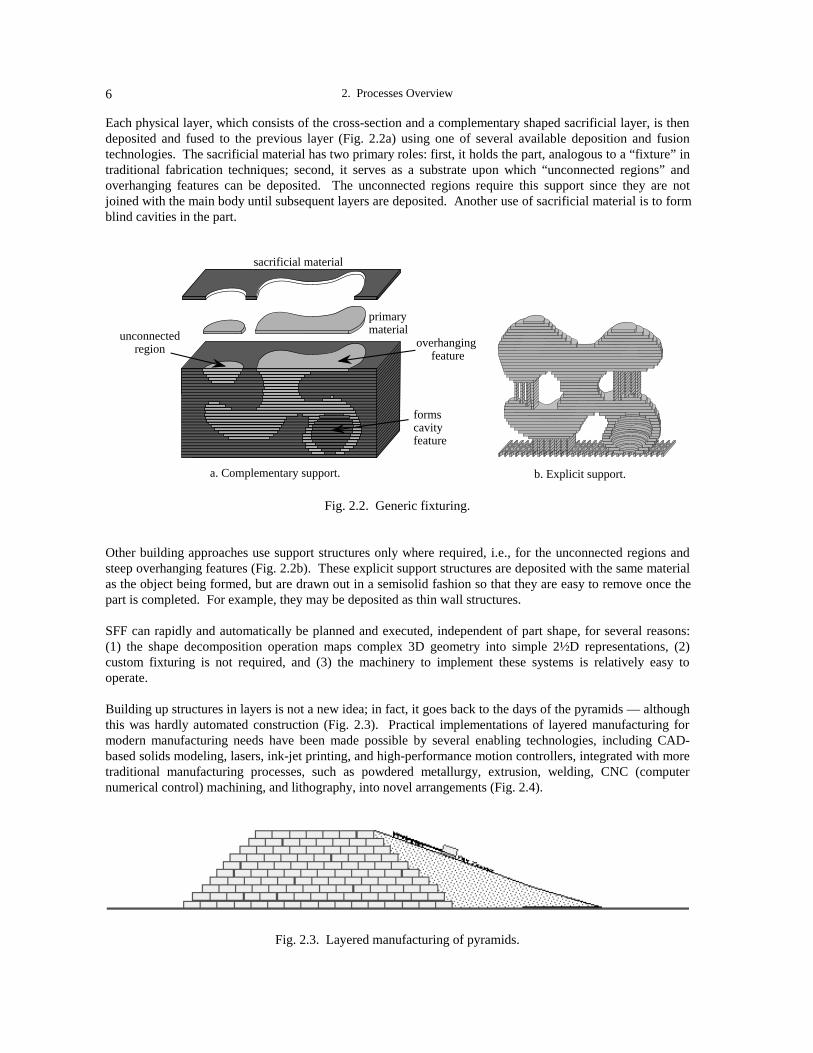
Each physical layer, which consists of the cross-section and a complementary shaped sacrificial layer, is thendeposited and fused to the previous layer (Fig. 2.2a) using one of several available deposition and fusiontechnologies. The sacrificial material has two primary roles: first, it holds the part, analogous to a “fixture” intraditional fabrication techniques; second, it serves as a substrate upon which “unconnected regions” andoverhanging features can be deposited. The unconnected regions require this support since they are notjoined with the main body until subsequent layers are deposited. Another use of sacrificial material is to formblind cavities in the part.
unconnected region
overhanging feature
sacrificial material
primary material
formscavity feature
a. Complementary support.
b. Explicit support.
Fig. 2.2. Generic fixturing.
Other building approaches use support structures only where required, i.e., for the unconnected regions andsteep overhanging features (Fig. 2.2b). These explicit support structures are deposited with the same materialas the object being formed, but are drawn out in a semisolid fashion so that they are easy to remove once thepart is completed. For example, they may be deposited as thin wall structures.
SFF can rapidly and automatically be planned and executed, independent of part shape, for several reasons:(1) the shape decomposition operation maps complex 3D geometry into simple 2½D representations, (2)custom fixturing is not required, and (3) the machinery to implement these systems is relatively easy tooperate.
Building up structures in layers is not a new idea; in fact, it goes back to the days of the pyramids — althoughthis was hardly automated construction (Fig. 2.3). Practical implementations of layered manufacturing formodern manufacturing needs have been made possible by several enabling technologies, including CAD-based solids modeling, lasers, ink-jet printing, and high-performance motion controllers, integrated with moretraditional manufacturing processes, such as powdered metallurgy, extrusion, welding, CNC (computernumerical control) machining, and lithography, into novel arrangements (Fig. 2.4).
Fig. 2.3. Layered manufacturing of pyramids.

Lee E. Weiss 7
Fig. 2.4. SFF enabling technologies.
Machining also plays an important role in rapid prototyping. CNC machining, however, is not generallyconsidered to be an SFF methodology, not only because it requires skillful human intervention to help planthe operations and to operate the equipment, but also because machining often requires custom fixturing andhas inherent geometric limitations. Still, machining can be effective in many rapid prototyping applications.In this JTEC/WTEC mission, the panel visited mostly with researchers and manufacturers of layeredmanufacturing processes. These processes are described in the next section. The panel also visited withseveral groups working on machining, and this work is described below in the section on the role ofmachining in RP.
SFF PROCESSES
The various SFF building strategies and deposition/fusion processes include photolithography, laser fusion,lamination, extrusion, and ink-jet printing. The figures included with the descriptions of these strategiesschematically represent these SFF systems. A more detailed description of machine designs, componenttechnologies used to implement each system, and CAD aspects will be presented in following chapters.Table 2.1 summarizes commercialized SFF systems.
Photolithography
Photolithography SFF systems build shapes using light to selectively solidify photocurable resins. There aretwo basic approaches: laser photolithography and photomasking. The laser photolithography approachdepicted in Fig. 2.5, which is currently the most widely used SFF RP technology, was first commercialized bythe U.S. company 3D Systems. Not only was 3D Systems the first company to successfully commercializethe stereolithography process, but the company must also be credited with both popularizing RP andestablishing a marketplace for RP technologies.
Traditional Technologies• powdered metallurgy• welding• extrusion• CNC machining• lithography
EnablingComponentTechnologies• lasers• ink-jet printers• motion control
SFF
CAD• solids modeling

2. Processes Overview8
Table 2.1Commercialized Rapid Prototyping Systems
in the United States, Europe, and Japan
Manufacturer Process Name Process Type Materials
United States
3D Systems StereolithographyApparatus (SLA)
laser photolithography acrylate, epoxy
Helisys Laminated ObjectManufacturing (LOM)
lamination, laser-cut paper, tape castings
Stratasys Fused DepositionModeling (FDM)
extrusion ABS, wax, nylon, gelcasting
DTM Selective Laser Sintering(SLS)
power-based, laserfusion
nylon, wax, polycarbonate,polymer-coated metal
Sanders Prototype Model Maker liquid jetting low-melt plastic
Soligen Direct Shell ProductionCasting (DSPC)
powder-based, 3Dprinting of binder
ceramics
BPM Ballistic ParticleManufacturing (BPM)
liquid jetting low-melt plastic
3D Systems Multi-Jet Modeling liquid jetting wax
Europe
EOS (Germany) STEREOS laser photolithography acrylate, epoxy
EOS (Germany) EOSINT powder-based, laserfusion
polyamide, polystyrene,metal alloy, resin-coatedsand
Cubital 1
(Germany/Israel)Solid Ground Curing(SGC)
photomasking acrylate, wax
Fockele & Schwarze(Germany)
LMS laser photolithography
Japan
CMET (NTT DataCommunications)
Solid Object UltravioletPlotter (SOUP)
laser photolithography epoxy
D-MEC (JSR/Sony) Sony’s Solid CreationSystem (SCS)
laser photolithography urethane acrylate
Kira Corp. Solid Center lamination, knife-cut paper
Teijin Seiki Solid Forming System(Soliform)
laser photolithography urethane acrylate, glass-filled resin
Denken Engineering Solid Laser Plotter (SLP) laser photolithography acrylate
Meiko Corp. Meiko laser photolithography acrylate
Mitsui Zosen COLAMM laser photolithography
Ushio, Inc. Uni-Rapid laser photolithography
1 Cubital is a jointly owned Israeli/German company with headquarters in Israel.

Lee E. Weiss 9
Recoating mechanism
Photocurable resin
Beam delivery
Laser
(e.g., galvo-mirrors)
Elevator
Fig. 2.5. Laser photolithography.
Laser photolithography systems have since been developed and manufactured in both Europe and Japan(Fig. 2.5 and Table 2.2). With the exception of Kira’s Solid Center, all RP machines manufactured in Japanare based on laser photolithography. While most laser photolithography systems use the building strategyrepresented in Fig. 2.5, there are significant differences in machine implementations, particularly in therecoating and beam delivery mechanisms and in the lasers. Chapter 9 describes these implementations indetail.
Table 2.2Laser Photolithography Systems
in the United States, Europe, and Japan
Manufacturer Process Name
United States
3D Systems Stereolithography Apparatus (SLA)
Europe
EOS (Germany) STEREOS
Fockele & Schwarze (Germany) LMS
Laser 3D (France) Stereophotolithography (SPL)
Japan
CMET (NTT Data Communications) SOUP
D-MEC (JSR/Sony) SCS
Teijin Seiki Solid Forming System (Soliform)
Denken Engineering Solid Laser Plotter (SLP)
Meiko Corp. Meiko
Mitsui Zosen COLAMM
Ushio, Inc. Uni-Rapid
2. Processes Overview10
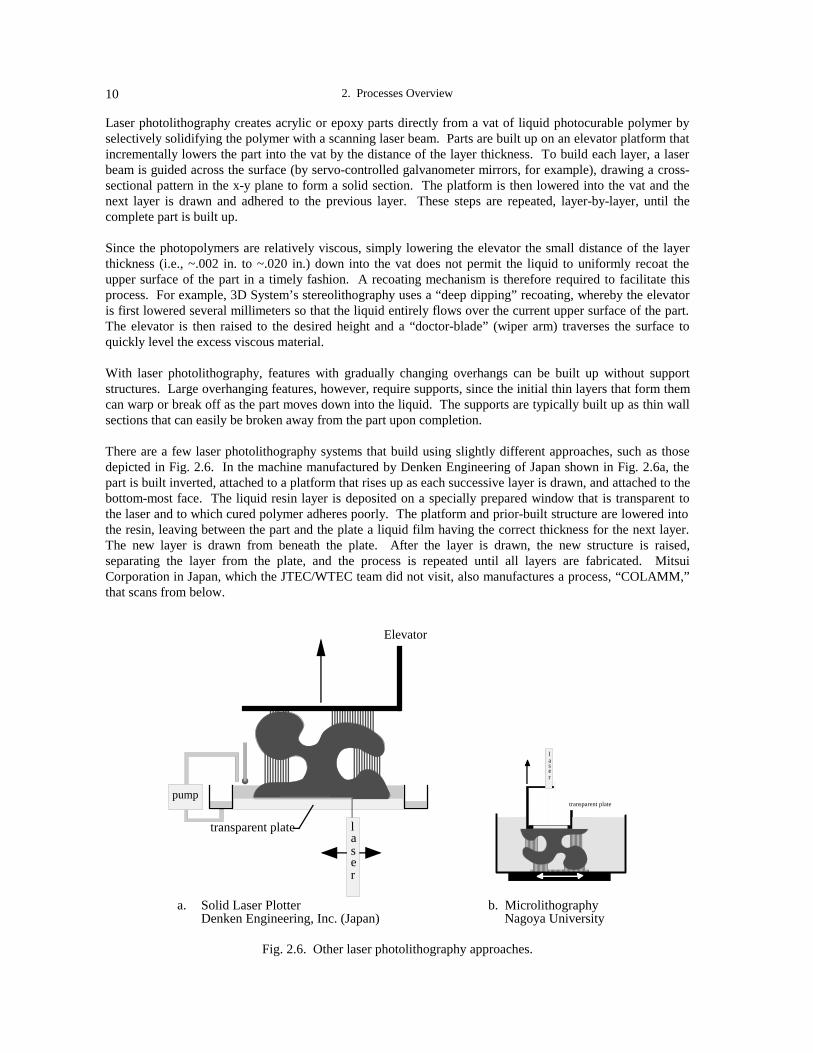
Laser photolithography creates acrylic or epoxy parts directly from a vat of liquid photocurable polymer byselectively solidifying the polymer with a scanning laser beam. Parts are built up on an elevator platform thatincrementally lowers the part into the vat by the distance of the layer thickness. To build each layer, a laserbeam is guided across the surface (by servo-controlled galvanometer mirrors, for example), drawing a cross-sectional pattern in the x-y plane to form a solid section. The platform is then lowered into the vat and thenext layer is drawn and adhered to the previous layer. These steps are repeated, layer-by-layer, until thecomplete part is built up.
Since the photopolymers are relatively viscous, simply lowering the elevator the small distance of the layerthickness (i.e., ~.002 in. to ~.020 in.) down into the vat does not permit the liquid to uniformly recoat theupper surface of the part in a timely fashion. A recoating mechanism is therefore required to facilitate thisprocess. For example, 3D System’s stereolithography uses a “deep dipping” recoating, whereby the elevatoris first lowered several millimeters so that the liquid entirely flows over the current upper surface of the part.The elevator is then raised to the desired height and a “doctor-blade” (wiper arm) traverses the surface toquickly level the excess viscous material.
With laser photolithography, features with gradually changing overhangs can be built up without supportstructures. Large overhanging features, however, require supports, since the initial thin layers that form themcan warp or break off as the part moves down into the liquid. The supports are typically built up as thin wallsections that can easily be broken away from the part upon completion.
There are a few laser photolithography systems that build using slightly different approaches, such as thosedepicted in Fig. 2.6. In the machine manufactured by Denken Engineering of Japan shown in Fig. 2.6a, thepart is built inverted, attached to a platform that rises up as each successive layer is drawn, and attached to thebottom-most face. The liquid resin layer is deposited on a specially prepared window that is transparent tothe laser and to which cured polymer adheres poorly. The platform and prior-built structure are lowered intothe resin, leaving between the part and the plate a liquid film having the correct thickness for the next layer.The new layer is drawn from beneath the plate. After the layer is drawn, the new structure is raised,separating the layer from the plate, and the process is repeated until all layers are fabricated. MitsuiCorporation in Japan, which the JTEC/WTEC team did not visit, also manufactures a process, “COLAMM,”that scans from below.
Elevator
laser
transparent plate
pump
laser
transparent plate
a. Solid Laser Plotter b. MicrolithographyDenken Engineering, Inc. (Japan) Nagoya University
Fig. 2.6. Other laser photolithography approaches.

Lee E. Weiss 11
The process represented in Fig. 2.6b is being developed by Professor Koji Ikuta of Nagoya University andoptimized for producing microscale parts — the laser spot size is 5 µm. (The panel did not visit with Prof.Ikuta). In this system a transparent plate is lowered into the vat to form a thin layer of liquid film over thepart being built up. The growing part remains stationary in the vat, and the vat is moved relative to a fixedlaser beam that passes through the plate, drawing the cross-section. The laser moves up with the plate tomaintain precise focusing on the film layer.
In contrast to “drawing out” each cross-section with laser photolithography, it is possible to image an entirecross-section in a single operation using photomasks. This approach was originally developed andcommercialized by Cubital (Israel/Germany).2 The Cubital system, called Solid Ground Curing (SGC), isdepicted in Fig. 2.7. In SCG, each cross-section is imaged onto an erasable mask plate produced by chargingthe plate via an ionographic process and then developing the image with an electrostatic toner (e.g., like theXerography process). The mask is then positioned over a uniform layer of liquid photopolymer, and anintense pulse of UV light is passed through it to selectively cure the material. Uncured photopolymer isremoved from the layer with a vacuum system and replaced with a low-melting-point, water-soluble wax thatserves as the sacrificial support. After the wax has cooled, the layer is milled to produce a flat surface. Thepattern on the exposed mask is erased by wiping off the toner, and the entire process is repeated. After thepart has been completed, the wax is removed by melting. The various processes used to implement SCG areperformed at different stations.
UV Light Source• Spray resin
• Expose mask
•Vacuum uncured resin
• Spray wax
• Mill flat
• Develop photomask
SoliderCubital, Inc. (Israel/Germany)
Fig. 2.7. Photomasking.
A unique feature of the photomasking approach is the capability to build multiple parts in a timely fashion ina single batch. Since the building time to form each layer is independent of the part geometry or size,multiple parts (e.g., the four replicates next to each other in Fig. 2.7) can be fabricated in the same time that itnormally takes to build a single part. Furthermore, the SGC system builds parts in a solid sacrificial waxmaterial that permits multiple parts to be packed into a single batch (e.g., the two rows of parts shown inFig. 2.7).
2 See footnote 1, page 8.
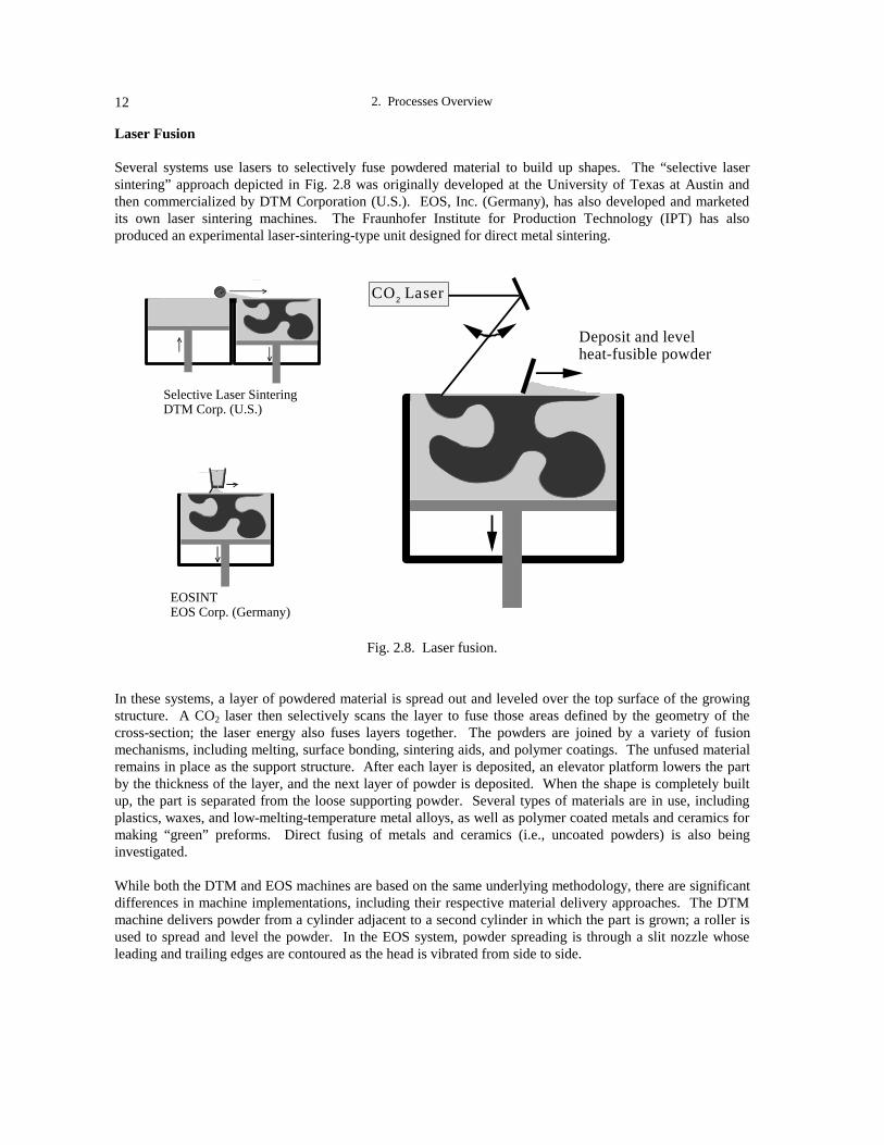
2. Processes Overview12
Laser Fusion
Several systems use lasers to selectively fuse powdered material to build up shapes. The “selective lasersintering” approach depicted in Fig. 2.8 was originally developed at the University of Texas at Austin andthen commercialized by DTM Corporation (U.S.). EOS, Inc. (Germany), has also developed and marketedits own laser sintering machines. The Fraunhofer Institute for Production Technology (IPT) has alsoproduced an experimental laser-sintering-type unit designed for direct metal sintering.
•
Selective Laser Sintering DTM Corp. (U.S.)
EOSINT EOS Corp. (Germany)
Deposit and level heat-fusible powder
CO Laser2
Fig. 2.8. Laser fusion.
In these systems, a layer of powdered material is spread out and leveled over the top surface of the growingstructure. A CO2 laser then selectively scans the layer to fuse those areas defined by the geometry of thecross-section; the laser energy also fuses layers together. The powders are joined by a variety of fusionmechanisms, including melting, surface bonding, sintering aids, and polymer coatings. The unfused materialremains in place as the support structure. After each layer is deposited, an elevator platform lowers the partby the thickness of the layer, and the next layer of powder is deposited. When the shape is completely builtup, the part is separated from the loose supporting powder. Several types of materials are in use, includingplastics, waxes, and low-melting-temperature metal alloys, as well as polymer coated metals and ceramics formaking “green” preforms. Direct fusing of metals and ceramics (i.e., uncoated powders) is also beinginvestigated.
While both the DTM and EOS machines are based on the same underlying methodology, there are significantdifferences in machine implementations, including their respective material delivery approaches. The DTMmachine delivers powder from a cylinder adjacent to a second cylinder in which the part is grown; a roller isused to spread and level the powder. In the EOS system, powder spreading is through a slit nozzle whoseleading and trailing edges are contoured as the head is vibrated from side to side.

Lee E. Weiss 13
Lamination
There are currently two commercialized SFF lamination systems. Laminated Object Manufacturing (LOM) isa lamination method that was developed and commercialized by Helisys Corporation (U.S.). LOM buildsshapes with layers of paper or plastic (Fig. 2.9a). The laminates, which have a thermally activated adhesive,are glued to the previous layer with a heated roller. A laser cuts the outline of the part cross-section for eachlayer. The laser then scribes the remaining material in each layer into a cross-hatch pattern of small squares(see insert in Fig. 2.9), and as the process repeats, the cross-hatches build up into tiles of support structure.The cross-hatching facilitates removal of this tiled structure when the part is completed. LOM builds up largeparts relatively rapidly because only contours are scanned. LOM is also being investigated by Helisys and theUniversity of Dayton for building up ceramic and reinforced composite shapes using layers of “green” tapecastings (i.e., sheets of bound powder); the final part must subsequently be sintered.
The only nonphotolithographic SFF system being produced in Japan is a lamination system manufactured byKira Corporation. While Kira’s basic building approach is the same as that used for the Helisys LOMmachine, the Kira Solid Center (SC) machine (Fig. 2.9b) is implemented in a significantly different manner.The SC machine uses standard printing paper that is fed into the machine using a conventional laser printer.The printer uses an adhesive-based toner to print the outline of the cross-section as well as a cross-hatchedbonding pattern on each piece of paper. A hot plate then laminates the paper to the previous layers. Thecross-sectional outline is then cut with a carbide knife that is mounted on a swivel base. Additional segmentsof “parting-plane” sections are also cut to facilitate removal of the support material.
laser printer with adhesive-based toner
b. Solid Center Kira Corp. (Japan)
heated plate
•
CO Laser2
adhesive-impregnated paper
Heated roller
a. Laminated Object Manufacturing Helisys, Corp. (U.S.)
Carbide knife
plain paper
Fig. 2.9. Lamination systems.
Internal cavities are hard to form with the lamination systems described above, since it is difficult to removethe sacrificial material from the internal regions. To address this issue, Case Western Reserve University andCAMLEM, Inc. (U.S.), are developing a lamination system using green tape castings with a separatesupporting material fugitive tape. Each section is individually cut with a laser and then stacked in place. Thefugitive tape is then burned out during the final firing process.

2. Processes Overview14
Extrusion
Extruding freeform shapes was first developed and commercialized by Stratasys, Inc. (U.S.). This approach,called Fused Deposition Modeling (FDM), deposits a continuous filament of a thermoplastic polymer or waxthrough a resistively heated nozzle (Fig. 2.10, top left). The material is delivered as a wire into the extrusionhead and heated to slightly above its flow point so that it solidifies relatively quickly after it exits the nozzle.It is possible to form short overhanging features without the need for explicit support; in general, however,explicit supports are needed. These are drawn out as thin wall sections that can easily be removed uponcompletion. Various U.S. investigators, including Rutgers University, Allied-Signal, Lone Peak Engineering,and Advanced Ceramics Research, are also exploring the use of FDM with thermoplastic wires and rodsloaded with ceramic powders to build “green” preforms.
Extrusion
slurry (wax & powder)
Multiphase Jet SolidificationFraunhofer Institutes IFAM and IPA (Germany)
metal injection molder
•
Fused Deposition Modeling Stratasys, Inc. (U.S.)
thermoplastic wireresistive heater
Fig. 2.10. Extruding freeform shapes.
Multiphase Jet Solidification (MJS) is another extrusion-based process (Fig. 2.10, bottom left). MJS is beingjointly developed by the Fraunhofer Institutes for Applied Materials Research (IFAM, Bremen) andManufacturing Engineering and Automation (IPA, Stuttgart). IPA is working on software development andIFAM on material aspects. MJS extrudes metal or ceramic slurries using metal injection molding technology.The slurry, which is about a 50/50 mixture of wax and metal or ceramic powder, is contained in a heatedvessel and pumped through an attached nozzle with a screw-activated plunger. The JTEC/WTEC team’shosts at IPA mentioned that commercialization may be through Fockele and Schwarze. The FraunhoferInstitutes have a German patent for MJS and are applying for a U.S. patent. The basic methodology ofdepositing 3D shapes by extrusion, in layers, is considered to be public domain. The Fraunhofer patentpertains to the feedstock (slurry composition), the heated material supply (up to 200ºC to liquefy the binderand obtain the desired viscosity), and the extrusion nozzle.
Ink-Jet Printing
Several SFF processes have taken advantage of ink-jet printing technology to print layers of structures. Thefirst process that successfully demonstrated “printing” of shapes was the Three-dimensional Printing (3DP)

Lee E. Weiss 15
process, depicted in Fig. 2.11a, which was developed at MIT as a method to form “green” preforms forpowdered metallurgy applications. While different powdered materials can be used, 3DP is currentlycommercialized by Soligen Corporation (U.S.) under the name Direct Shell Production Casting (DSPC) forcreating ceramic shells and cores for casting applications. In 3DP, the part is built up in a bin that is fittedwith a piston to incrementally lower the part into the bin. Powder (such as alumina) is dispensed from ahopper above the bin, and a roller is used to spread and level the powder. An ink-jet printing head scans thepowder surface and selectively injects a binder (such as colloidal silica) into the powder. The binder joins thepowder together into those areas defined by the geometry of the cross-section. The unbound powder becomesthe support material. When the shape is completely built up, the “green” structure is fired, and then the part isremoved from the unbound powder. 3DP of metal powders, such as stainless steel bound with a polymericbinder, is also being explored; subsequent infiltration of the matrix is then required for densification.
binder
AAAA
Deposit and level bindable powder
AAAA
molten plastic
molten wax
slab cutter
.
AAA
molten plastic
a. Three Dimensional Printing MIT, and Soligen, Inc. (U.S.)
b. Ballistic Particle Manufacturing BPM, Inc. (U.S.)
c. Model Maker Sanders, Inc. (U.S.)
molten plastic
d. Multi-Jet Modeling 3D Systems, Inc. (U.S.)
96 element print head
Fig. 2.11. Ink-jet printing systems.
Other processes use ink jets to directly deposit low-melting target materials. Ballistic Particle Manufacturing(BPM), which was developed and commercialized by BPM Technology, Inc. (U.S.), uses a piezoelectricjetting system to deposit microscopic particles of molten thermoplastic (Fig. 2.11b). Like FDM and SLA,support structures are required for “unconnected” features. The supports are deposited in a perforated patternto facilitate removal. The BPM jet head, however, is mounted on a 5-axis positioning mechanism so thatoverhanging features can be deposited without support, as the figure shows.

2. Processes Overview16
The Model Maker system (Fig. 2.11c) of Sander’s, Inc. (U.S.), dispenses both a low-melting-temperaturethermoplastic and a separate wax support material. In addition, it incorporates a slab cutter to plane eachlayer to the precise thickness.
In other commercial developments, 3D Systems, Inc. (U.S.), has just introduced a new ink-jet prototypingsystem, “Multi-Jet Modeling,” (Fig. 2.11d), which uses a printing head with 96 individual jets that deposits alow-melting-temperature thermoplastic. Using the same material the support structure is deposited as thin,needle-like structures.
In other research efforts, the Technical University of Munich (not visited by the panel) is developing a“modified” three-dimensional printing process that injects streams of UV-curable binder resins under a UVlight. Also, investigators at MIT and the University of California, Irvine, are developing jetting systems todeposit metal alloys.
ROLE OF MACHINING IN RP
The main competition to SFF-based rapid prototyping systems is NC (numerical control) machining, usedtypically in small model-making shops. In comparison with current SFF processes, machining can produceparts with superior accuracy and surface finish and having a much broader range of materials, especiallytooling steels. Furthermore, if only 2D drawings are available, then machining by a skilled model maker canoften be executed more quickly than the time it takes to first create the 3D model required for SFFprocessing. Machining, therefore, remains strategically important to industry in both Europe and Japan, duein part to the relatively slow dissemination of 3D CAD in both areas. There are also concerns about theinability of current SFF processes to (1) produce parts with the accuracy and surface finish required for manyengineering models, (2) build with a wide variety of engineering materials, and (3) directly produce high-quality metal parts for production tooling applications.
Completely automated CNC machining would have a significant impact on rapid prototyping. Current CNCsystems, however, are not generally considered to be SFF technologies for the following reasons: they stillrequire skillful human intervention to help plan the operations and to operate the equipment; custom fixturingand special tooling is often required; and machining has inherent geometric limitations (Fig. 2.12). However,just as SFF process performance capabilities are expected to improve, automated CNC planning capabilitiesare also expected to continue to improve with the proliferation of 3D CAD modeling systems. In the future,both CNC and SFF will remain important technologies for RP needs.
xxx
yyy
zzz
roll
pitch
yaw
mill .01
ball .22
ball .33
Decompose
Fixture
Rotate
EDM
no cavity
ReorientCustom Fixturing
Special Tooling
Fig. 2.12. Why isn’t CNC machining an SFF process?

Lee E. Weiss 17
Material Removal Processes
While improving the capabilities of automated CNC planning systems is important, there is also a need toimprove the machining processes themselves. There is interesting work in both Germany and Japan onmachining and other material removal processes. The main application area for these processes is in rapidtool manufacturing. Tooling fabrication relaxes some geometry constraints; for example, undercut features arenot normally required.
Lasercaving, which process is used by LCTec, Inc. (Germany), is being refined by the Bavarian Laser Center(BLZ). It is a material removal process used to cut cavities into metal or ceramic stock in a downward, layer-by-layer fashion. A high-power laser and oxygen source are simultaneously directed at the surface to be cutand swept across the cutting path. The heated metal oxidizes, and oxidized chips break away due todifferential thermal expansion between the underlying unoxidized material and the oxide fragment (Fig. 2.13).
laser oxygen
Fig. 2.13. Lasercaving.
The system includes a 5-axis CNC vertical milling machine and a 750 W CO2 laser. Parts are mounted on themill and moved relative to the fixed beam. The claimed accuracy is 0.05 mm, and the material removal rate is5 mm3/min. Overall machining times can be reduced by first roughing out material at a higher rate using thelaser in a melting mode that removes material at a rate of 1,000 mm3/min. Surface roughness is about 5 µm.Primary applications BLZ is exploring are cutting cavities in tools and texturing tooling surfaces.
The JTEC/WTEC team saw examples of steel dies and leather-like textured patterns; their surface quality wasexcellent. These surfaces must be glass-beaded to remove oxidation; otherwise, no additional processing isrequired. Lasercaving can be a powerful method for building and texturing tools with fine detail and smallfeatures. In Japan, Professor Nakagawa of Tokyo University has extensive leading-edge research in the useof high-speed machining, i.e., spindle speeds of ~100,000 RPM. He is particularly interested in the use ofhigh-speed machining for rapid tooling manufacturing.
Processes That Combine Material Addition and Removal
There are also efforts to investigate combining the benefits of material additive processes (especially that theysimplify planning) with the benefits of material removal processes (that their accuracy and surface finish aresuperior). The primary application area has been for tooling manufacturing. The Fraunhofer IPT hasdeveloped an experimental system, called “Laser Generated RP,” which uses laser welding to melt metalpowder as it drops from a coaxial laser/powder distribution cone (Fig. 2.14a). Other concentric cones withinthe probe deliver shroud gas and fluids for cooling. The system uses either a 900 W CO2 laser or a 1,000 W

2. Processes Overview18
Nd:YAG laser. Within the work chamber is a 2½D milling cutter to finish the walls of the metal part andimprove tolerances. IPT representatives claim that this unit produces full-density parts, but they did notdisclose their deposition and cutting strategies to the JTEC/WTEC team. They showed the team both thinwall and solid parts made of steel from this experimental unit. IPT plans to commercially develop this systemwith a die casting machine tool company over the next few years. With significant funding from itscommercial partner, chances of commercializing this technique appear promising.
a. Laser Generated RP Fraunhofer IPT (Germany)
laser
powder feeder
Laser welding
b. Large-scale lamination Professor Nakagawa, Tokyo University
Fig. 2.14. Combining material addition with material removal.
In addition to his work in high-speed machining, Professor Nakagawa is developing lamination processes tobuild up large-scale tooling, such as forming dies for automobile bodies. Individual sections of material areshaped with CNC cutting and then stacked up to form the tool (Fig. 2.14b). However, neither the method ofregistration nor the joining process was disclosed to the team.
The addition/removal processes described above apparently do not incorporate support structures. CarnegieMellon and Stanford universities are developing an addition/removal process, Shape DepositionManufacturing (SDM), which does incorporate support structures. In SDM, a CAD model is first sliced into3D layered structures (i.e., the outer surface of each layer maintains the 3D geometry of the original model).Layer segments are then deposited as near-net shapes and then machined to net shape before additionalmaterial is deposited (Fig. 2.15). The sequence for depositing and shaping the primary and support materialsis dependent upon the local geometry; the idea is to decompose shapes into layer segments such that undercutfeatures need not be machined, but are formed by previously shaped segments.
Remove
Deposit
Microcasting example CNC machining
stainless steel
sacrificial copper
Fig. 2.15. Shape deposition manufacturing.
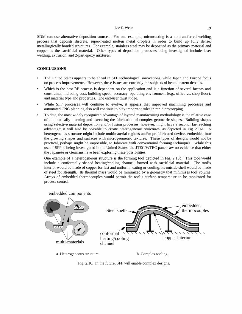
Lee E. Weiss 19
SDM can use alternative deposition sources. For one example, microcasting is a nontransferred weldingprocess that deposits discrete, super-heated molten metal droplets in order to build up fully dense,metallurgically bonded structures. For example, stainless steel may be deposited as the primary material andcopper as the sacrificial material. Other types of deposition processes being investigated include laserwelding, extrusion, and 2-part epoxy mixtures.
CONCLUSIONS
• The United States appears to be ahead in SFF technological innovations, while Japan and Europe focuson process improvements. However, these issues are currently the subjects of heated patent debates.
• Which is the best RP process is dependent on the application and is a function of several factors andconstraints, including cost, building speed, accuracy, operating environment (e.g., office vs. shop floor),and material type and properties. The end-user must judge.
• While SFF processes will continue to evolve, it appears that improved machining processes andautomated CNC planning also will continue to play important roles in rapid prototyping.
• To date, the most widely recognized advantage of layered manufacturing methodology is the relative easeof automatically planning and executing the fabrication of complex geometric shapes. Building shapesusing selective material deposition and/or fusion processes, however, might have a second, far-reachingadvantage: it will also be possible to create heterogeneous structures, as depicted in Fig. 2.16a. Aheterogeneous structure might include multimaterial regions and/or prefabricated devices embedded intothe growing shapes and surfaces with microgeometric textures. These types of designs would not bepractical, perhaps might be impossible, to fabricate with conventional forming techniques. While thisuse of SFF is being investigated in the United States, the JTEC/WTEC panel saw no evidence that eitherthe Japanese or Germans have been exploring these possibilities.
One example of a heterogeneous structure is the forming tool depicted in Fig. 2.16b. This tool wouldinclude a conformally shaped heating/cooling channel, formed with sacrificial material. The tool’sinterior would be made of copper for fast and uniform heating or cooling; its outside shell would be madeof steel for strength. Its thermal mass would be minimized by a geometry that minimizes tool volume.Arrays of embedded thermocouples would permit the tool’s surface temperature to be monitored forprocess control.
embeddedthermocouplesSteel shell
copper interiorconformal heating/cooling channel
embedded components
multi-materials
a. Heterogeneous structure. b. Complex tooling.
Fig. 2.16. In the future, SFF will enable complex designs.

2. Processes Overview20

21
CHAPTER 3
HISTORICAL PERSPECTIVE
Joseph J. Beaman
TECHNOLOGY
The early roots of rapid mechanical prototyping technology can be traced to at least two technical areas:topography and photosculpture.
Topography
As early as 1890, Blanther (1892) suggested a layered method for making a mold for topographical reliefmaps. The method consists of impressing topographical contour lines on a series of wax plates, cutting thewax plates on the contour lines, and then stacking and smoothing the wax sections. This produces bothpositive and negative three-dimensional surfaces that correspond to the terrain indicated by the contour lines.After suitable backing of these surfaces, a printed paper map is then pressed between the positive andnegative forms to create a raised relief map. This is shown in Fig. 3.1.
Fig. 3.1. Layered mold relief map proposed by Blanther (1892).

3. Historical Perspective22
Perera (1940) proposed a similar method for making a relief map by cutting contour lines on cardboard sheetsand then stacking and pasting these sheets to form a three-dimensional map. Further refinements of thisapproach were made by Zang (1964), who suggested using transparent plates with topographical detailinscribed on each plate, and Gaskin (1973), who described a three-dimensional geological teaching device.In 1972, Matsubara of Mitsubishi Motors (1974) proposed a topographical process that uses photo-hardeningmaterials. In this process, a photopolymer resin is coated onto refractory particles (e.g., graphite powder orsand), which are then spread into a layer and heated to form a coherent sheet. Light (e.g., from a mercuryvapor lamp) is selectively projected or scanned onto this sheet to harden a defined portion of it. Theunscanned, unhardened portion is dissolved away by a solvent. The thin layers formed in this way aresubsequently stacked together to form a casting mold. In 1974, DiMatteo (1976) recognized that these samestacking techniques could be used to produce surfaces that are particularly difficult to fabricate by standardmachining operations. Examples he mentions include propellers, air foils, three-dimensional cams, andforming of dies for punch presses. In one embodiment (Fig. 3.2), contoured metallic sheets are formed by amilling cutter, then joined in layered fashion by adhesion, bolts, or tapered rods. This process has obvioussimilarity to the earlier 19th century work.
Fig. 3.2. Layered mold of stacked sheets by DiMatteo (1974).
In 1979, Professor Nakagawa of Tokyo University began to use lamination techniques to produce actual toolssuch as blanking tools (Nakagawa et al. 1979), press forming tools (Kunieda and Nakagawa 1984), andinjection molding tools (Nakagawa, Kunieda, and Liu 1985). Of particular note, Nakagawa mentions thepossibility of complex cooling channels in injection molds (Nakagawa, Kunieda, and Liu 1985).
Photosculpture
Photosculpture arose in the 19th century in attempts to create exact three-dimensional replicas of objects,including human forms (Bogart 1979). One somewhat successful realization of this technology was designedby Frenchman François Willème in 1860. In his method, shown in Fig. 3.3, a subject or object was placed ina circular room and simultaneously photographed by 24 cameras placed equally about the circumference ofthe room. The silhouette of each photograph was then used by an artisan in Willème’s studio (Fig. 3.4) tocarve out 1/24th of a cylindrical portion of the figure.
In an attempt to alleviate the labor-intensive carving step of Willème’s photosculpture, Baese (1904)described a technique using graduated light to expose photosensitive gelatin, which expands in proportion toexposure when treated with water. Annular rings of the treated gelatin are then fixed on a support to make areplica of an object, as shown in Fig. 3.5. Similar techniques and improvements were developed by Monteah(1924).
In some of the earliest work in Japan, Morioka (1935, 1944) developed a hybrid process combining aspectsof photosculpture and topography. This method (Fig. 3.6) uses structured light (black and white bands oflight) to photographically create contour lines of an object. The lines can then be developed into sheets andcut and stacked, or projected onto stock material for carving.

Joseph J. Beaman 23
Fig. 3.5. Photographic process for the development of plastic objects by Baese (1904).
Fig. 3.4. François Willème’s photosculpturing studioin Paris, about 1870 (Bogart 1979; photocourtesy of George Eastman House).
Fig. 3.3. Admiral Farragut sits, late 1860s, forphotosculpture (Bogart 1979; photocourtesy of George Eastman House).

3. Historical Perspective24
Fig 3.6. Process for manufacturing a relief by Morioka (Morioka 1935, 1944).
In 1951, Munz (1956) proposed a system that has features of current stereolithography techniques (Fig. 3.7).He disclosed a system for selectively exposing a transparent photo emulsion in a layerwise fashion, whereeach layer comes from a cross-section of a scanned object. These layers are created by lowering a piston in acylinder and adding appropriate amounts of photo emulsion and fixing agent. After exposing and fixing, theresulting solid transparent cylinder contains an image of the object. Subsequently this object can be manuallycarved or photochemically etched out to create a three-dimensional object.
Fig. 3.7. Process by Munz (1956) to reproduce a three-dimensional image of an object.

Joseph J. Beaman 25
Early Solid Freeform Fabrication
In 1968, Swainson (1977) proposed a process to directly fabricate a plastic pattern by selective three-dimensional polymerization of a photosensitive polymer at the intersection of two laser beams. Parallel workwas conducted at Battelle Laboratories (Schwerzel 1984). The essential features of this process, termedphotochemical machining, are depicted in Fig. 3.8. The object is formed by either photochemically cross-linking or degrading a polymer by simultaneous exposure to intersecting laser beams. Although laboratoryhardware was constructed for this process, a commercially viable process was apparently not achieved.
Fig. 3.8. Photosculpture process using intersecting laser beams, by Swainson (1977).
A powder process that has more in common with laser surface cladding techniques than photosculpture wasproposed in 1971 by Ciraud (1972). This disclosure describes a process for the manufacture of objects froma variety of materials that are at least partially meltable. In order to produce an object, small particles areapplied to a matrix by gravity, magnetostatics, or electrostatics, or positioned by a nozzle located near thematrix. The particles are then heated locally by a laser, electron beam, or plasma beam. As a consequence ofheating, the particles adhere to each other to form a continuous layer. As Fig. 3.9 shows, more than one laserbeam can be used in order to increase the strength of the union between the particles.
Fig. 3.9. Powder laser process proposed by Ciraud (1972).

3. Historical Perspective26
Hideo Kodama of Nagoya Municipal Industrial Research Institute was the first to publish an account of afunctional photopolymer rapid prototyping system (Kodama 1981). In his method, a solid model is fabricatedby building up a part in layers, where exposed areas correspond to a cross-section in the model. He studiedthree different methods for achieving this (Fig. 3.10):
a. using a mask to control exposure of the UV source and immersing the model downward into a liquidphotopolymer vat in order to create new layers
b. using a mask as in (a), but positioning the mask and exposure on the bottom of the vat and drawing themodel upward to create a new layer
c. immersing the model as in (a), but using an x-y plotter and an optical fiber to expose the new layer
Fig. 3.10. Schematics of three photopolymer systems studied by Kodama (1981).
A second, parallel but independent, effort was conducted by Herbert at 3M Corporation (1982). Herbertdescribes a system that directs a UV laser beam to a photopolymer layer by means of a mirror system on an x-y plotter (Fig. 3.11). In Herbert’s experimental technique, a computer is used to command a laser beamacross a layer, the photopolymer vessel is then lowered (~ 1 mm), and additional liquid photopolymer is thenadded to create a new layer.
Fig. 3.11. Herbert’s photopolymer process (1982).

Joseph J. Beaman 27
Active Patents
Besides those described above, there are numerous active patents that cover existing commercial processes.Table 3.1 lists the most prominent patents.
Table 3.1Active Rapid Prototyping Patents
NAME TITLE FILED COUNTRY
Housholder Molding process December 1979 U.S.
Murutani Optical molding method May 1984 Japan
Masters Computer automated manufacturing process and system July 1984 U.S.
André et al. Apparatus for making a model of an industrial part July 1984 France
Hull Apparatus for making three-dimensional objects bystereolithography
August 1984 U.S.
Pomerantz et al. Three-dimensional mapping and modelling apparatus June 1986 Israel
Feygin Apparatus and method for forming an integral objectfrom laminations
June 1986 U.S.
Deckard Method and apparatus for producing parts by selectivesintering
October 1986 U.S.
Fudim Method and apparatus for producing three-dimensionalobjects by photosolidification; radiating an uncuredphotopolymer
February 1987 U.S.
Arcella et al. Casting shapes March 1987 U.S.
Crump Apparatus and method for creating three-dimensionalobjects
October 1989 U.S.
Helinski Method and means for constructing three-dimensionalarticles by particle deposition
November 1989 U.S.
Marcus Gas phase selective beam deposition: three-dimensional, computer-controlled
December 1989 U.S.
Sachs et al. Three-dimensional printing December 1989 U.S.
Levent et al. Method and apparatus for fabricating three-dimensional articles by thermal spray deposition
December 1990 U.S.
Penn System, method, and process for making three-dimensional objects
June 1992 U.S.
Early Parts
Although very intricate parts produced by rapid prototyping equipment are now common, the first parts out ofthese types of systems required a good deal of faith that improvements would occur. Shown in Fig. 3.12 arethree early parts from different systems. The Housholder part was made from an embodiment that included agrid for separating mold material (concrete and water) from casting material (dry concrete). The Herbert partwas created in August 1979. It is not known exactly when the Kodama and Housholder parts were created.

3. Historical Perspective28
Fig. 3.12. Three early rapid prototyping parts; from left to right by Kodama, Herbert, and Housholder.
COMMERCIAL DEVELOPMENT
Early Development
In the earliest commercial development, Willème’s photosculpture studio was commercially successful from1861 to 1868 but eventually went out of business, probably due to the labor involved in hand sculpting with apantographic (tracing) instrument. The next known commercial attempt was Swainson’s formation ofFormagraphic Engine Company in 1977. Formagraphic later formed an alliance with Battelle Laboratoriesand changed its name to Omtec Replication. It appears that this effort was abandoned before a commercialprocess was developed. Also in 1977, DiMatteo formed an company called Solid Photography that was spunout of Dynell Electronics Corporation when Dynell merged with United Technologies. As a result, anaffiliated retail outlet called Sculpture by Solid Photography was opened in New York City (Fig. 3.13). In1981, Solid Photography changed its name to Robotic Vision. Solid Photography and the company SolidCopier operated as subsidiaries of Robotic Vision until 1989 (Lightman 1996).
Fig. 3.13. Sculpture by Solid Photography process (Bogart 1979;photos courtesy of Soho Image Works [no longer in business]).

Joseph J. Beaman 29
U.S. Development
As Table 3.2 shows, the first commercial rapid prototyping machine was introduced in 1988 by 3D Systemswhen it shipped the SLA-1 to three customers.
Table 3.2U.S. Commercial Development of RP Systems
Company Process VentureStart Shipment Notes
Aaroflex Stereolithography 1995 n/a License from DuPont
BPM Ink jet 1989 1995
DTM Selective laser sintering 1987 1992 Operated a service bureau from 1990-93
DuPont Somos Stereolithography 1987 n/a Licensed to Teijin Seiki 1991, Aaroflex 1995
Helisys Laminated object 1985 1991 Founded as Hydronetics
Light Sculpting Photomasking 1986 n/a Operates as a service bureau
Quadrax Stereolithography 1990 1990 Technology acquired by 3D in 1992
Sanders Prototyping Ink jet 1994 1994 Partially developed at E-Systems
Soligen 3D printing 1991 1993 Operates as a service bureau
Stratasys Fused deposition 1988 1991
3D Systems Stereolithography 1986 1988 First commercial shipment of equipment
European and Japanese Development
Table 3.3 shows the chronology for commercial development of rapid prototyping processes in Europe andJapan. As can be seen by comparing these charts, the United States has led the way in commercialization ofnew rapid prototyping equipment. Also, it can be seen that in the United States there are many different typesof technology, while in Japan, with the exception of Kira, all the Japanese vendors use laser photopolymertechniques. There is only one U.S. laser photopolymer company that is presently shipping equipment: 3DSystems.
Table 3.3European and Japanese Commercial Development of RP Systems
Company Process Venture Started Shipment Notes
CMET Stereolithography 1988, Japan 1990
Cubital Photomasking 1987, Israel 1991
Denken Stereolithography 1985, Japan 1993
DMEC Stereolithography 1990, Japan 1990
EOS Stereolithography,Selective Laser Sintering
1989, Germany 1990
Fockele & Schwarze Stereolithography 1991, Germany 1994 Service bureau since 1992
Kira Laminated object 1992, Japan 1994
Meiko Stereolithography 1991, Japan 1994
Mitsui Stereolithography 1991, Japan 1991
Sparx Laminated object Sweden 1994 Foam machine
Teijin Seiki Stereolithography 1991, Japan 1992 License from DuPont
Ushio Stereolithography Japan 1994
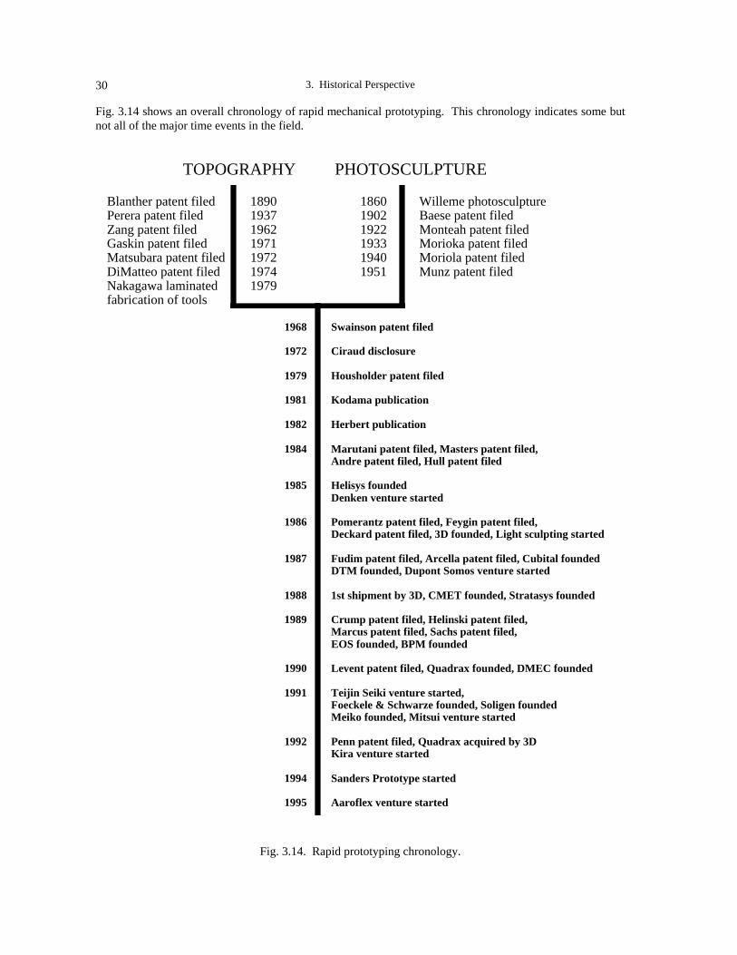
3. Historical Perspective30
Fig. 3.14 shows an overall chronology of rapid mechanical prototyping. This chronology indicates some butnot all of the major time events in the field.
PHOTOSCULPTURE
Blanther patent filed Perera patent filed Zang patent filed Gaskin patent filed Matsubara patent filed DiMatteo patent filed Nakagawa laminated fabrication of tools
1890 1937 1962 1971 1972 1974 1979
1860 1902 1922 1933 1940 1951
Willeme photosculpture Baese patent filed Monteah patent filed Morioka patent filed Moriola patent filed Munz patent filed
1968 1972 1979 1981 1982 1984 1985 1986 1987 1988 1989 1990 1991 1992 1994 1995
Swainson patent filed Ciraud disclosure Housholder patent filed Kodama publication Herbert publication Marutani patent filed, Masters patent filed, Andre patent filed, Hull patent filed Helisys founded Denken venture started Pomerantz patent filed, Feygin patent filed, Deckard patent filed, 3D founded, Light sculpting started Fudim patent filed, Arcella patent filed, Cubital founded DTM founded, Dupont Somos venture started 1st shipment by 3D, CMET founded, Stratasys founded Crump patent filed, Helinski patent filed, Marcus patent filed, Sachs patent filed, EOS founded, BPM founded Levent patent filed, Quadrax founded, DMEC founded Teijin Seiki venture started, Foeckele & Schwarze founded, Soligen founded Meiko founded, Mitsui venture started Penn patent filed, Quadrax acquired by 3D Kira venture started Sanders Prototype started Aaroflex venture started
TOPOGRAPHY
Fig. 3.14. Rapid prototyping chronology.

Joseph J. Beaman 31
REFERENCES
Baese, C. 1904. U.S. Patent 774,549.
Blanther, J. E. 1892. U.S. Patent 473,901.
Bogart, M. 1979. In art the ends don’t always justify means. Smithsonian 104-110.
Ciraud, P. A. 1972. FRG Disclosure Publication 2263777.
DiMatteo, P. L. 1976. U.S. Patent 3,932,923.
Gaskin, T. A. 1973. U.S. Patent 3,751,827.
Herbert, A. J. 1982. Solid object generation. J. Appl. Photo. Eng. 8(4)(August): 185-88.
Kunieda, M. and T. Nakagawa. 1984. Development of laminated drawing dies by laser cutting. Bull. ofJSPE 353-54.
Kodama, H. 1981. Automatic method for fabricating a three-dimensional plastic model with photo-hardening polymer. Rev. Sci. Instrum. 1770-73.
Lightman, A. 1996. Personal communication.
Matsubara, K. 1974. Japanese Kokai Patent Application, Sho 51[1976]-10813.
Monteah, F. H. 1924. U.S. Patent 1,516,199.
Morioka, I. 1935. U.S. Patent 2,015,457.
_____. 1944. U.S. Patent 2,350,796.
Nakagawa, T., et al. 1979. Blanking tool by stacked bainite steel plates. Press Technique 93-101.
Nakagawa, T., M. Kunieda, and S. Liu. 1985. Laser cut sheet laminated forming dies by diffusion bonding.In Proc. 25th Int’l. MTDR Conf., 505-510.
Perera, B. V. 1940. U.S. Patent 2,189,592.
Swainson, W. K. 1977. U.S. Patent 4,041,476.
Schwerzel, R. E., et al. 1984. Three-dimensional photochemical machining with lasers. In Appl. of Lasers toInd. Chem., SPIE, 90-97.
Zang, E. E. 1940. U.S. Patent 3,137,080.

3. Historical Perspective32

33
CHAPTER 4
NEEDS, GOALS, AND OBJECTIVES
Robert L. Brown
The general needs, goals, and objectives for rapid prototyping are essentially the same in Europe and Japan,although the emphases may be different. Within a country, differences in needs also occur between andwithin industries. In Japan the tendency is to emphasize accuracy as the predominant consideration, while inEurope there is a movement to develop techniques to produce metal components and tooling. Both regionsare interested in building rapid prototype (RP) plastic injection molds to produce a few hundred prototypeparts in a commodity-type plastic. In the following discussion, the order in which needs and objectives areaddressed does not necessarily represent the order of priority in any one country or industry; indeed, prioritiesvary between and within industries and companies.
RAPID PROTOTYPING
In general, the implementation of rapid prototyping by layer-building techniques has developed slower inEurope and Japan than in the United States. This may be a result of both Europe and Japan enjoying a greaterinfrastructure of skilled tool makers and model makers than does the United States. Also, U.S. industry tendsto embrace new computer-related technologies more quickly.
Europe
Compared to the United States, Germany has been slower to adopt rapid prototyping in place of conventionalmachining techniques because many companies have not seen the need for it. There are still many small tooland machine shops in Germany that can produce a quality product at a reasonable price in a short time.Germany’s machine shops are very competitive, with small tool shop owners willing to work nights andweekends to meet delivery dates.
Japan
Twenty years ago in Japan it was not uncommon to discuss with a company a new product or product designonly to be presented the next day with a prototype of the proposed product incorporating features from theprevious day’s discussions. With skilled model makers and a culture that values dedication, Japanesecompanies took well-deserved pride in such feats. These capabilities still exist in Japan, albeit with an agingskilled workforce that is not being replaced by younger skilled practitioners at the rate older workers areleaving the industry. This is evident in both the jewelry and foundry pattern-making businesses, where RP

4. Needs, Goals, and Objectives34
equipment is being introduced for production purposes to fill the shortfall in skilled workers. Other than inthese cases and in specific companies discussed in this report, there has not been as great a perceived need forRP techniques in Japan as in the United States.
Still, both European and Japanese companies are using rapid prototyping, which suggests there is a need notbeing fulfilled by the conventional machine shops. Whether the driver is lower price, faster delivery, orcuriosity to evaluate a new technology is not clear. Certainly, the driver is not dimensional accuracy, materialproperties, or surface finish, as all of these qualities can still be better achieved by conventional machiningtechniques.
3D CAD SOLID MODELING
The key element in the efficient use of RP is application of 3D solid modeling software, starting at the pointof design inception. Without this tool, transfer of design data can be time-consuming and laborious. There isless use of 3D solid modeling software in Europe than in the United States, and even less in Japan. This maybe partially due to the recession Japan has endured during the past several years, which has limited capitalspending in most companies.
Representatives of a Japanese service bureau speculated to the JTEC/WTEC team that 10% of large Japanesecompanies own 3D CAD solid modeling software, and 1% know how to use it. Others estimate that 3% ofJapanese designers can use 3D solid modelers. Officials at another service bureau told panelists that 80% oftheir customers supply CAD files, but the files are only in 2D. Generally, prototypes can be made in Japanquicker, cheaper, and more accurately by conventional machine shop practices if designs are supplied as 2Dfiles. Only when parts are small, have complicated surfaces, and are designed in 3D CAD solid modeling canprototypes be built more quickly and less expensively by RP techniques.
There is an interest in Japan in finding easier methods for designers to build RP models without having to usefull 3D solid modeling software. For example, Sony wants to develop 2D CAD software that would be easierto use than solid modeling packages, but that could produce 3D RP models with specialized control software.The goal of Professor Fukuda of the Tokyo Metropolitan Institute of Technology is to develop a CAD systemthat allows the designer to use a “more intuitive approach” to modify and manipulate the model (Sites, 1996,117-118). At the time of the JTEC/WTEC panel’s visits in Japan, large companies like Mitsubishi ElectricEngineering Company were ordering 3D CAD solid modeling software from the United States, but untilrecently only relied on 2D drawing tools (Electronic News 1996, 32).
RAPID PROTOTYPING EQUIPMENT
For RP equipment, the primary needs, regardless of country, are lower equipment cost, lower maintenancecosts, greater accuracy, better surface finish, and higher speed; however, relative importance of these factorsdoes vary.
Equipment Costs
While some new U.S. equipment makers are focusing on lowering costs, such as for desktop RP units, thedrive to develop low-cost equipment does not appear to be a major consideration in Europe. The Europeanequipment maker EOS is positioning itself as a high-cost premier producer of equipment, and Cubital unitshave been consistently at the high end of the cost range.
In Japan, RP equipment equivalent to that available in the United States is considerably more expensive. Incomparison, machine tool centers in the same size class as an RP machine are less expensive thanstereolithography units. Yet, inexpensive, albeit lower-accuracy, units are available for the jewelry industry

Robert L. Brown 35
from such companies as Meiko, which produces a photo resin-based unit with a price tag of ~$140,000,including software. For some Japanese equipment makers, lowering equipment costs is becoming anobjective. D–MEC representatives mentioned price as a customer concern; consequently, this Japanesecompany plans to develop lower-cost machines in the future.
Maintenance Costs
For RP equipment using lasers, the lasers themselves can be the highest maintenance cost item. Fockele andSchwarze (Sites, 1996, 14-17) has been evaluating diode-pumped Nd lasers with frequency triplers to replacethe argon ion lasers that are more expensive to maintain. EOS has been offering these diode-pumped Ndlasers commercially on its STEREOS MAX laser stereolithography units for some time and has sold severalsuch systems to customers. Diode-pumped Nd lasers are expected to have longer life, be less expensive toreplace, and consume less power.
In Japan, maintenance contracts appear to be comparable in cost to those in the United States, but resins aremuch more expensive.
Accuracy and Surface Finish
Improvement of accuracy and surface finish are often primary considerations for users of RP equipment. Asmore companies attempt to build prototype plastic injection mold cavities by RP, the need for greateraccuracy and surface finish in the RP master copy will increase, since some degradation of part dimensionsoccurs in the injection molding process.
Daimler Benz representatives indicated that with stereolithography they can routinely achieve 100 micronaccuracy in the x-y direction and 250 microns in the z direction. They would like 70 micron accuracy in allthree directions. (Such tolerances are already achievable in the United States.) JTEC/WTEC panelists talkedwith observers of the European RP industry who indicated that it is not always clear what user needs are foraccuracy in a prototype part; in some cases, current dimensional tolerances are sufficient.
Stereolithography is the most popular RP method in use in Japan. When panelists asked why selective lasersintering units are not as popular in Japan as in the United States, the explanation offered was thatstereolithography provides the greatest accuracy. Generally, Japanese companies would like to see higheraccuracy capabilities, where tolerances of ±0.03 mm can be routinely achieved (Sites, 1996, CMET andOlympus site reports, 42-46, 95-98). Representatives of Shonan Design Company, a service bureau,mentioned to panelists that their customers indicate they will increase orders for RP parts as accuracy andsurface finish improve.
Speed
Speed appears to be an important consideration in Europe, as shown by the fact that BMW underwrote thefirst EOS stereolithography unit based on a speed-performance standard. Automaker Daimler Benz wouldalso like to see speed increases in the recoating operation, and other companies indicated that speed is animportant consideration.
Compared to the United States, less consideration appears to be placed on speed in Japan. As an example,less emphasis is placed by some Japanese RP equipment manufacturers on providing software toautomatically design structural supports for the parts being built, leaving customers to laboriously designsupports by manual techniques (Sites, 1996, CMET/Asahi Denka report, 42-46). However, a Sonyrepresentative did mention speed as one attribute of Sony’s next-generation RP machines (Sites, 1996, D-MEC report, 47-53).

4. Needs, Goals, and Objectives36
MATERIALS
There is a clear need to improve the mechanical properties of the stereolithography resins and plasticscurrently being used. Cubital is searching for an epoxy-type material that will match the properties of 3DSystems’ epoxy resin and for a wax-like material that can be used for investment casting of metal parts. TheInstitute for Polymer Testing and Polymer Science at the University of Stuttgart has helped EOS develop apolystyrene for selective laser sintering. As laser-sintered, this material has relatively low strength and isgenerally used for investment casting patterns or visualization models. Although it can be infiltrated toproduce high-strength rigid parts, polyamide (nylon) is generally used for parts requiring higher strengthand/or toughness. Users such as Daimler Benz desire models that have the mechanical properties of ABS;that is, with ductility to test snap fit, flexible hinges, and other functional properties of a design.
Full-density resins, which may be produced by stereolithography, selective laser sintering, or infiltration, willnot replicate the mechanical properties of a part produced by plastic injection molding, due to rheologicalconsiderations in the molded plastic parts that can align the anisotropic polymers to produce differentmechanical properties in different directions within the part. In a similar manner, sintered metal parts do notreplicate the mechanical properties of fully dense wrought or cast products. Properties in plastic parts thatapproach what might be expected from production parts can only be achieved using rapid tooling to produceinjection molded parts. Equipment and resin makers, research institutes, and others, see the need to developrapid tooling methods and materials to (1) produce parts that approach the mechanical properties ofproduction parts, and (2) be able to make a few hundred parts for functional testing.
Stereolithography Resins — Properties and Cost
A prime consideration in both Europe and Japan is the development of resins that have improved mechanicalproperties, better long-term dimensional stability, higher temperature resistance, and lower cost. Bettermechanical properties give designers greater latitude in using RP models to test functional characteristics(Sites, 1996, Olympus report, 95-98). Several companies expressed the desire to achieve propertiesequivalent to those of ABS.
Greater dimensional stability over time (i.e., 30 days) is also needed. When Japan’s Ministry of InternationalTrade and Industry (MITI) made funds available to develop better resins, one attribute that it specified as anobjective was time-dependent dimensional stability (Sites, 1996, D-MEC report, 47-53). Resin makers arealso developing epoxy-based UV curable resins to reduce warping.
Higher thermal stability is desirable in rapid prototyping resins when used for (a) producing plastic injectionmolds that are used for making a few hundred prototype parts in a common plastic, and (b) making functionalmodels that have to withstand elevated temperatures, such as for functional testing of the intake manifold ofan internal combustion engine.
Stereolithography resins are also expensive. Service bureaus such as Schneider in Germany would like to seeprice breakthroughs in resins to make them more competitive (Sites, 1996, 7). A single large vat ofstereolithography resin can cost $100,000 in Japan. For companies that make large parts, such as intakemanifolds for engines, this is a significant issue (Sites, 1996, Hino Motors report, 58-9).
Metals
In Europe there is considerable activity in devising processes that will directly yield metal components. Inprocesses using powder metals in selective laser sintering-type methods, the resulting RP products are porous.They can be furnace-sintered to consolidate the objects, but this results in extensive shrinkage and loss ofdimensional accuracy. The alternative is to infiltrate with a lower-melting-point alloy or a high-temperatureepoxy resin that does not require furnace sintering. Infiltrated products represent a compromise: they do nothave good high-temperature properties and often have too low a hardness and wear resistance compared tofully dense steel objects; however, they are often adequate for pilot tooling for making a few thousand

Robert L. Brown 37
injection-molded parts. The Fraunhofer Institute for Production Technology (IPT) is developing a process todirectly make fully dense metal parts by a laser fusion process called Laser-Generated RP, which incorporatesa milling cutter to trim the walls and surfaces of each layer to improve accuracy and surface finish. Theprocess was first shown publicly December 1995 at Euromold 95 in Frankfurt, Germany. Similar techniquesare being pursued in the United States, but without integrated machining.
There are two forms of metal tooling: pilot tooling and production tooling. The long-term objective ofEuropean research institutes and equipment makers is to develop RP hardware and processes to produceproduction tooling. However, accuracy is a major issue. In producing pilot metal tooling, achievement of ahigh degree of accuracy and of mechanical properties approaching those of wrought metal are seriousconsiderations. Achieving both of these properties at the same time is not currently possible.
It is clear that in Europe there is a need for metal parts produced by rapid prototyping for tooling andstructural components. At the RP service bureau Schneider Prototyping near Frankfurt, 15-20% of orders arefor metal parts and tooling. Panelists were told that German companies often send their rapid prototypingmodels or CAD files to the United States to have them cast into metal parts because price and quality arebetter than in Germany. German casting foundries have been slow to learn casting methods that use rapidprototyping masters for investment casting patterns.
The JTEC/WTEC panel found no company in Japan developing RP processes to directly build metalcomponents, but did find considerable interest in making metal components by investment casting, metalspray, and so forth.
Ceramics and Paper
Compared to the United States, there does not appear to be much interest in Europe and Japan in buildingceramic parts by RP. At the time of the panel’s visit, several companies and institutes in Europe wereworking on developing ceramic processes, but the emphasis appeared to be on polymer resins and metalproducts.
In Japan, Kira Corporation, which builds a small laminated paper (or object) manufacturing (LOM) machine,would like to see its process capable of greater accuracy. It is now limited to ±0.1 mm/25 mm in thehorizontal plane (x-y direction) and ±0.3 mm/25 mm in the vertical build direction (z direction). Swelling ofthe completed part in the z direction due to humidity can also be a problem, which Kira researchers hope tocorrect with an improved paper (Sites, 1996, 75-83).
PLASTIC INJECTION MOLDED PROTOTYPES
Tooling to make molds that will produce 200-500 plastic parts in 3-4 weeks is a goal of SchneiderPrototyping. The Fraunhofer Institute for Chemical Technology (ICT) is experimenting with making epoxyresin plastic injection molds using stereolithography. EOS offers a selective laser sintering unit specificallydesigned for making metal molds using a proprietary bronze-based metal powder. At the time of the panel’svisit, the Fraunhofer IPT was experimentally using this machine to produce parts using stainless steel,aluminum, and coated ceramics powders, although it was not specifically designed to support these materials.
The Japanese service bureau Shonan Design has developed a technique for making injection mold cavitiesthat can produce 200 injection molded parts in 2-3 weeks using Teijin Seiki’s stereolithography units andglass-filled resin. However, accuracy is no better than ± 0.3 mm over the length of small parts (~12 mm) forup to 200 parts. Japanese equipment and resin makers that compete with Teijin Seiki also are working todevelop resins that can be used to make prototype molds. Laser sintering was generally not being used inJapan at the time of the panel’s site visits, nor did panelists see evidence that Japanese firms were attemptingto develop such techniques. Since then, over two dozen selective laser sintering machines have been installedin the Asian Pacific Rim. At least two of these machines are in Japan.

4. Needs, Goals, and Objectives38
EDUCATION
Several of the 46 Fraunhofer institutes in Germany are developing educational courses in various aspects ofrapid prototyping for small- and medium-sized companies. Judging from the number of RP conferences andcommercial RP courses in Europe, there is a strong interest in such programs. Warwick, Nottingham, andBuckingham universities in England have developed or are developing consortiums with industry that aredesigned to educate industrial personnel as well as to pursue specific developmental goals.
While Japanese companies traditionally have not worked closely with universities or research institutes, thisis changing. Japanese industry has apparently begun approaching universities for help in educating theengineering workforce in order to help companies keep up with rapidly changing technologies. To cite aspecific example, Terry T. Wohlers of Wohlers Associates, in reviewing a draft of this report, indicated thatin June 1996, Prof. Nakagawa of Tokyo University described to him “a one-year, $1.5 million Japanesegovernment project with Toyota Electronic and Telecom Institute in Nagoya. The focus of this work is toproduce production tooling by laser-cutting and laminating steel sheets. Toyota has produced and used asmany as 100 dies using Nakagawa’s sheet lamination approach for prototype tooling… [Also,] Nakagawa isworking with Professor Takeuchi of Tokyo Electronic and Telecom Institute on high-speed 5-axismachining.” The JTEC/WTEC panel interviewed several Japanese who are doing outstanding academic workin support of RP (Sites 1996, 117-124) and learned of several new industry-government programs that focuson new manufacturing technologies. However, the panel learned of no specific RP programs in Japan thatjointly involve industry, university, and government.
GOVERNMENT SUPPORT
It is difficult to construct a simple picture of how funds flow in Europe from government agencies to industryand academia to further the development of RP. This is because of the high number of overlapping andinterwoven local government, federal government, and European Community agencies’ programs that providesupport. For example, there is support for RP-related programs from the Commission of the EuropeanCommunities through BRITE/EuRAM, RACE, ESPRIT, COMPLAN, and EARP. Some programs likeEARP (European Action on Rapid Prototyping), which is under BRITE/EuRAM (Basic Research ofIndustrial Technologies for Europe/European Research on Advanced Materials), have very limited funds fordistribution. “BRITE funds basic research while EuRAM focuses on European research on advancedmaterials. In the 1993-94 period, BRITE/EuRAM supported most of the European RP projects. ESPRIT isinvolved more on the computing side. The EUREKA program is supported jointly by the EC and nationalgovernments, whereas BRITE and ESPRIT are funded exclusively by the EC.”1 In addition, there are federaland state government programs. When seven Fraunhofer institutes initiated their alliance to coordinate theirRP programs (the JTEC/WTEC team visited four of these. See Sites 1996, 18-33), the German governmentgave the alliance DM 5 million (~$3.5 million) over two years to fund start up. In other RP efforts,approximately 50% of the operating funds to support the Bayerisches Laserzentrum (Bavarian Laser Center)come from local state government, and the innovative service bureau Fockele and Schwarze received startupfunding through a Westphalia government program that further backed its loans through a local bank (Sites,1996, 1-3, 14-17).
In Japan, MITI’s position appears to be that RP is not a serious commercial process because of the poorsurface finish, material properties, and accuracy of its products. (A number of Japanese companies, on theother hand, do consider RP to be a serious commercial process.) The Ministry is not yet committed toinvesting substantial resources to support RP. Government officials estimated at the time of the JTEC/WTECvisit that it would be at least eight years before RP becomes a serious commercial technology and beforeJapanese RP equipment companies will compete in sales on a world scale. Currently, RP represents less than1% of the NC (numerical control) machine tool market and therefore enjoys only minor support from MITIcompared to its past support of Japan’s machine tool industry, which has 48% of the world machine tool
1 This explanation was contributed by Terry T. Wohlers.

Robert L. Brown 39
market. However, MITI does fund a ¥800 million 4-year RP program that is administered through thegovernment laboratory, Center for Plastic Materials, which distributes ¥200 million per year. The funds areavailable to industry to support research and development activities in four areas: (1) resins, (2) hardware, (3)software, and (4) applications. Japan Synthetic Rubber Company, which owns the stereolithographyequipment manufacturer D-MEC, is the only company obtaining funds from MITI for materials developmentunder this program. INCS, Inc., has a ¥30 million project to develop RP tooling and another ¥800,000 todevelop medical models.
Japan’s Ministry of Education, Science, and Culture is moving from a position of promoting basic science inuniversities to stressing the importance of manufacturing. In another departure from general past practices,MITI intends to fund manufacturing projects directly at universities. As these changes only appear to berecent, panelists had little or no discussion in Japan about RP training programs for industry. In general,prefectural governments sponsor local programs for industry and education, which may be another source offunds to support development activities.
In summary, it is apparent that European industry, universities, and research institutes are identifying andaddressing practical needs in RP and are moving forward with determination to establish well-thought-outdevelopment programs that will produce a solid foundation of basic knowledge on which to build furtheradvancements in RP. In Japan, the links between industry, academia, and research institutes do not seem tobe quite as strong as in Europe. It is clear to this panel that the Japanese have a long-term plan to be major, ifnot dominant, competitors on a global scale in RP. They have demonstrated in other fields that they canproduce a superior product by identifying practical needs and quietly addressing all details to produce acomplete solution.
REFERENCES
Electronic News. 1996. (January 8): 32.
Sites. 1996. This reference designates the companion volume to this JTEC/WTEC report: Prinz, F. B.,ed. JTEC/WTEC panel report on rapid prototyping in Europe and Japan. Vol. II. Site reports.Baltimore, MD: Loyola College. NTIS Report #PB96-199583.1.

4. Needs, Goals, and Objectives40

41
CHAPTER 5
MATERIALS — OVERVIEW, PLASTICS, AND RESINS
Paul S. Fussell
STATE OF RP MATERIALS DEVELOPMENT
The aim of rapid prototyping is to rapidly produce a product. At the moment, this product is made, for themost part, of inferior material that permits the user to show notion, or perhaps generate a few other partssuitable for limited testing. This condition has been true since the initial systems were commercialized, whilethe promise of true engineering products is only slowly being realized through machine and materialimprovements. Heralding this achievement is a gradual progression up the maps of material properties.Although Fig. 5.1 reduces the complexity of material choice and performance to just the two parametersmodulus and strength, it shows a simplified schematic of this progression.
0.01
0.1
1
10
100
1000
0.1 1 10 100 1000 10000
DULUS , E (GPA)
STRENGTH, σ (MPa)y
Al Alloys
Steels
Glass
Wood|| to grain
Wood| to grain
Nylon
Rubber
Diamond
Early Photopolymer Systems
Current Photopolymer Systems
Fig. 5.1. Modulus-strength materials property chart, after Ashby (1989).
5. Materials42
The progression, however, is not sufficiently advanced to speak to the real need of the rapid productdevelopers: this community needs rapid prototype materials that behave, with high fidelity, like engineeringmaterials, and specifically engineering polymers. Rapid prototyping is having a useful effect on productvisualization and other limited fields, but the lack of rapid prototyped engineering materials is a significantbarrier, perhaps the single most significant barrier, to dramatic growth of this technology and its profoundimpact on the product development endeavor. For the panel’s observations during this review, there is littlevisible work that will produce this new material.
Given non-engineering material, the viability of any rapid prototype effort hinges upon the integrated successof material, machine, and the information used to drive the device. This strong interdependence manifestsitself in every nuance of the equipment’s design, performance, and eventual optimization. There arenumerous examples of this linkage in extant rapid prototyping technology. One is 3D Systems’ ability tosuccessfully commercialize QuickCast™. This was made possible by the use in the SLA-250 of the epoxyresin SR 5170, with its properties of accuracy, dimensional stability, and weakening in the presence of high-temperature steam, in conjunction with successful design of the internal lattice structure of the solid object(Jacobs 1995). It is fair to say that the epoxy material has substantially added to the shareholder’s value in3D Systems, Inc., as well as changed the resin market in the United States and Europe.
Improvement and optimization of rapid prototyping approaches is equally dependent upon both material andmachine design. For DTM to successfully introduce the nylon material, it had to apply a new level ofsophistication in thermal control of the powder column. Similarly, 3D Systems had to make significantcontrol parameter alterations to deal with the difference between the kinetics of epoxy cure and the earlieracrylate systems.
In commercial rapid prototyping, there is also the delicate art of finding a balance between materialproperties, material cost, equipment cost, ease of use, and overall system performance and throughput. Eachvendor of equipment chooses a different price point for its technology and vigorously proceeds to develop itsrelevance to the marketplace. This is certainly as true in Europe and Japan as it is in North America.
It is therefore germane to study the state of materials development in rapid prototyping, as well as theinterweaving of material design and machine design. This chapter explores the state of materialsdevelopment — polymers, metals, and ceramics — in the European and Japanese rapid prototypingenvironments, with limited comparison to North America.
PLASTICS
The use of plastics in the rapid prototyping industry is, broadly speaking, broken into two categories: (1)reactive polymer systems such as the photopolymers used in stereolithography equipment, and (2) nonreactivepolymers used, for example, in the sinter-based systems. Research and development in these areas have beenequally effective in moving the materials closer to the property performances of engineering plastics.
In terms of market share, the North American rapid prototyping materials market is dominated by CibaGeigy’s epoxy line of resins (SR 5170, 5180, and 5190), and by DTM’s powder systems, including nylon,wax, and polycarbonate.
Reactive Polymer Systems
The polymers of this phylum are thermoset in character: that is, the polymer chains grow and cross-linkduring curing. The cure system is initiated by energy input to the resin, and in rapid prototyping systems,most generally by light (usually ultraviolet). The basics of these reactions are amply covered in Johnson(1994) and Pang (1995) .
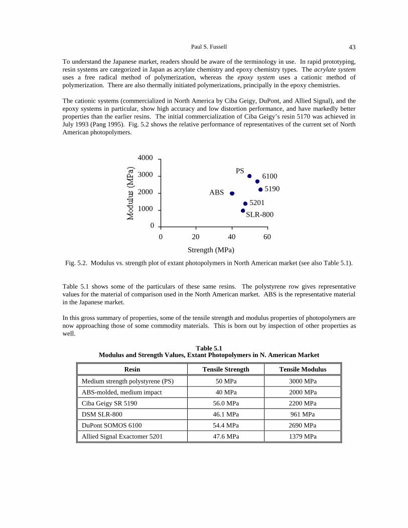
Paul S. Fussell 43
To understand the Japanese market, readers should be aware of the terminology in use. In rapid prototyping,resin systems are categorized in Japan as acrylate chemistry and epoxy chemistry types. The acrylate systemuses a free radical method of polymerization, whereas the epoxy system uses a cationic method ofpolymerization. There are also thermally initiated polymerizations, principally in the epoxy chemistries.
The cationic systems (commercialized in North America by Ciba Geigy, DuPont, and Allied Signal), and theepoxy systems in particular, show high accuracy and low distortion performance, and have markedly betterproperties than the earlier resins. The initial commercialization of Ciba Geigy’s resin 5170 was achieved inJuly 1993 (Pang 1995). Fig. 5.2 shows the relative performance of representatives of the current set of NorthAmerican photopolymers.
PS
5190ABS
SLR-800
6100
5201
0
1000
2000
3000
4000
0 20 40 60
Strength (MPa)
Fig. 5.2. Modulus vs. strength plot of extant photopolymers in North American market (see also Table 5.1).
Table 5.1 shows some of the particulars of these same resins. The polystyrene row gives representativevalues for the material of comparison used in the North American market. ABS is the representative materialin the Japanese market.
In this gross summary of properties, some of the tensile strength and modulus properties of photopolymers arenow approaching those of some commodity materials. This is born out by inspection of other properties aswell.
Table 5.1Modulus and Strength Values, Extant Photopolymers in N. American Market
Resin Tensile Strength Tensile Modulus
Medium strength polystyrene (PS) 50 MPa 3000 MPa
ABS-molded, medium impact 40 MPa 2000 MPa
Ciba Geigy SR 5190 56.0 MPa 2200 MPa
DSM SLR-800 46.1 MPa 961 MPa
DuPont SOMOS 6100 54.4 MPa 2690 MPa
Allied Signal Exactomer 5201 47.6 MPa 1379 MPa

5. Materials44
RESINS
Table 5.2 summarizes the rapid prototype manufacturer and material vendor relationship.
Table 5.2Resin Suppliers to RP Equipment Manufacturers
Equipment Manufacturer Resin Supplier
Cubital Unknown
Fockele & Schwarze Allied Signal/DuPont
EOS DuPont
Laser 3D Self-formulated
Teijin Seiki Teijin Seiki/DuPont
CMET Asahi Denka
D-MEC Japan Synthetic Rubber
Denken Self-formulated (680 nm λ)
Meiko Shikoku Kenka Industry
Resin Approaches
The JTEC/WTEC panel found the European and Japanese work in filled, or loaded, resins to be interesting.This is a partially undeveloped market in North America, although DuPont’s SOMOS 2100 and 5100 seriesresins are filled. The new work is being pushed in Japan, and the Institute for Polymer Testing and PolymerScience at the University of Stuttgart has also done some investigative work.
The filled systems generally have a much higher viscosity: they produce a stiff artifact after curing; they canbe wear-resistant depending upon the matrix and the reinforcement; and they can have the effect of increasingaccuracy by simply replacing the variable polymer with an inert component. At the same time, they reducecost, again, by simply substituting a cheap material for the more costly polymer.
The panel investigated 3 filled resin systems now being developed by three manufacturers:
• Teijin Seiki tooling application• Japan Synthetic Rubber tooling application• Laser 3D (France) cost control, accuracy
Table 5.3 summarizes some of the properties of these manufacturers’ resin systems. The uses of these resinsare detailed in Chapter 11 on tooling applications of rapid prototyping.
Table 5.3Filled Resin Characteristics
Manufacturer Resin Viscosity Filler Particle Size, wgt %
Teijin Seiki TSR 752 49,000 5 components ~30–50 µm
JSR SCR 600 3400 glass 15 µm, 70%
Laser 3D MR 100 ~10,000 glass* 10–20 µm, 60%
* Laser 3D suggests that it is using SiC, ceramic, and wax as well, although the panel did not observe these being used.

Paul S. Fussell 45
The European market primarily uses resins produced by North America-based manufacturers. The Japanesemarket, however, primarily uses suppliers based in Japan. These suppliers include Asahi Denka, JapanSynthetic Rubber, and Teijin Seiki.
Asahi Denka Resins
Asahi Denka has an exclusive arrangement with CMET of the Mitsubishi group. Its resins are all epoxy-based and have been in the market since about 1990. Several of the U.S. and European manufacturersindicated they were aware of these systems, but the North American market didn’t see an epoxy system until1993. The properties of the Asahi Denka resins are interesting, with high strength and high modulus values,as Fig. 5.3 and Table 5.4 show. It is apparent, though, that Asahi Denka and CMET have chosen to have arelatively brittle material. In comparison, North American manufacturers produce resins that have somewhatreduced modulus and strength properties but are less brittle.
The HS 673 is apparently the most popular argon ion laser material. This material does show dimensionalchange with humidity, growing from 0.1% to 0.3% initially, and 0.5-0.6% with long exposure.
HS 673
0
1000
2000
3000
4000
0 20 40 60 80
Strength (MPa)
Fig. 5.3. Asahi Denka resins: modulus vs. strength properties (see also Table 5.4).
Table 5.4Asahi Denka Materials: Modulus vs. Strength
Resin Laser Strength Modulus Elongation Impact
HS 671 Ar 29 MPa 2746 MPa 1.3% 1.3 ft–lb/in
HS 672 Ar 48 MPa 2648 MPa 2.8% 1.8 ft–lb/in
HS 673 Ar 67 MPa 3334 MPa 3.1% 2.2 ft–lb/in
HSX–A–4 Ar, experimental 35 MPa 1863 MPa 3.7% 3.1 ft–lb/in
HS 660 HeCd 60 MPa 3236 MPa 2.5% 2.2 ft–lb/in
HS 661 HeCd 41 MPa 2354 MPa 2.9% 2.0 ft–lb/in
HS 662 HeCd 37 MPa 2059 MPa 4.7% 3.7 ft–lb/in
HS 663 HeCd 12 MPa 481 MPa 16.0% 13.8 ft–lb/in
HS 666 HeCd 6 MPa 69 MPa 10.0% 14.5 ft–lb/in

5. Materials46
Figures 5.4 and 5.5 show the relationships of elongation and impact resistance vs. strength. Note that CMETpublishes unnotched IZOD data; thus, it is difficult to compare to engineering data for conventional materials.The HS 673 shows low elongation, low impact resistance, and high strength.
HS 673
HS 666
HS 663
0.0%2.0%4.0%6.0%8.0%
10.0% 12.0% 14.0% 16.0%
0 20 40 60 80
Strength (MPa)
Fig. 5.4. Asahi Denka resins: strain at failure vs. strength (see also Table 5.4).
HS 673
HS 663
0
2
4
6
8
10
12
14
16
0 20 40 60 80
Strength (MPa)
Fig. 5.5. Asahi Denka resins: impact vs. strength properties (see also Table 5.4).
Japan Synthetic Rubber Resins
Sony has commercialized the Japan Synthetic Rubber (JSR) resins in the DMEC devices. These are allacrylate urethane resins. As shown in Table 5.5 and graphically in Fig. 5.6, these are less strong and less stiffthan the epoxy systems. The JSR material SCR 310 is intended to provide low warpage service, and SCR600 is an experimental resin filled with glass. (The SCR 600 work is funded by MITI.)
Figures 5.7 and 5.8 show the elongation and impact resistance tradeoffs that JSR made in formulating thematerials.

Paul S. Fussell 47
JSR (Tensile)
SCR 500SCR 200
SCR 600
0
500
1000
1500
2000
0 20 40 60
Strength (MPa)
Fig. 5.6. Japan Synthetic Rubber resins: modulus vs. strength properties (see also Table 5.5).
Table 5.5Japan Synthetic Rubber Material Properties
Resin TensileStrength
TensileMod
Strain atFailure
FlexStrength
FlexMod
Impactnotched
Impactunnotched
TgHeatDefl’t
SCR 100 31 MPa 1.2 GPa 5% 62 MPa 1.4 GPa0.37
ft-lb/in3.1
ft-lb/in 95°C 54°C
SCR 200 59 MPa 1.4 GPa 15%0.55
ft-lb/in2.75
ft-lb/in 93°C 50°C
SCR 500 59 MPa 1.6 GPa 10%0.37
ft-lb/in3.3
ft-lb/in 140°C 75°C
SCR 310 39 MPa 1.2 GPa 30%2.75
ft-lb/in8.6
ft-lb/in 110°C 43°C
SCR 600 32 MPa 1.1 GPa 5.6% 382 MPa 1.2 GPa2.2
ft-lb./in7.3
ft-lb./in 93°C 44°C
SCR 300
0
0.1 0.2
0.3 0.4
0.5
0 20 40 60
Strength (MPa)
SCR 310 SCR 600
0
1
2
3
0 20 40 60
Strength (MPa)Fig. 5.7. JSR resins: strength vs. elongation Fig. 5.8. JSR resins: strength vs. impact resistance.
(see also Table 5.5). (see also Table 5.5).

5. Materials48
Teijin Seiki Resins
Teijin Seiki is committed to the tooling market in Japan. The company has determined that prototype tooling,if of sufficient accuracy, will be appealing to a very large market. Its material development began only twoyears ago; formerly it purchased DuPont SOMOS materials from North America. Its resin TSR 752 is a filledresin showing very high stiffness and reasonable strength. Its sole application is tooling. Fig. 5.9 shows themodulus vs. strength information, and Table 5.6 summarizes the material data.
13%
TSR 752
0
5000
10000
15000
0 20 40 60 80
Strength (MPa)Fig. 5.9. Teijin Seiki resins: modulus vs. strength properties (see also Table 5.6).
Table 5.6Teijin Seiki Material Data
Resin TensileStrength
TensileModulus
Strain atFailure
FlexStrength
FlexModulus
TSR 752 76 MPa 14,000 MPa 1% 97 MPa 14,000 MPa
TSR 800 61 MPa 2900 MPa 13% 100 MPa 2800 MPa
Overview
Fig. 5.10 shows an overview of the major Japanese resins.
Additional Approaches
In addition to the major materials and vendors discussed above, there are other approaches to material issues.Cubital has developed, originally with DSM, material for its Solid Ground Curing system. These arebasically acrylate systems, although Cubital has felt the marketing pressure from the Ciba Geigy epoxysystem and is attempting to develop such a resin as well.
Table 5.7 shows the elongation and heat deflection temperature of Cubital resins, and Fig. 5.11 shows themodulus vs. strength mapping. The softness of these resins shows that parts from these materials will becompetitive with the other acrylates, but not with the epoxies.

Paul S. Fussell 49
HS 662
SCR 600
TSR 752
HS 673
TSR 800 PS
SCR 310
ABS 5190
SCR 500 0
2000
4000
6000
8000
10000
12000
14000
0 20 40 60 80
Strength (MPa)Fig. 5.10. Comparative overview of Japanese resin systems.
Table 5.7Cubital Resins: Elongation, Heat Deflection Temperature
Resin Type ElongationHeat DeflectionTemperature
G5601 10% 40°C
XA7510 20% 54°C
X611 10% 51°C
“Epoxy” 10% 80°C
"Epoxy"
X611XA7510
G5601
0
250
500
750
1000
1250
1500
0 20 40 60
Strength (MPa)
Fig. 5.11. Cubital resins: modulus vs. strength properties.

5. Materials50
Denken has used a single acrylate sensitive to its visible light laser. Since it is now converting to a frequencydoubled laser (at 473 nm λ), the company will be able to explore other resin systems.
Similarly, Meiko has a specialized resin for use with its HeCd laser. This resin gives adequate performancefor the jewelry modeling niche market Meiko has developed.
THERMOPLASTIC SYSTEMS
Almost all development of thermoplastic systems is taking place in North America. EOS in Germany has aline of polymers for its EOSINT machines that includes polystyrene for investment casting, a nylon-likematerial, and a polymer-coated sand material. EOS uses the sand in its EOSINT-S device to make one-of-a-kind sand cores for precision sand casting. In the European market there has been considerable interest inthis product, especially for those applications that require very complex sand cores.
OTHER SYSTEMS
Kira Corporation makes parts in paper in a process that uses knives to cut the outline of the layer rather thanusing a laser to burn the outline. Kira’s work, however, is still grounded in conventional office papers. Itscustomers have recognized that better paper is needed, and Kira is apparently beginning to study thepossibility of using rice paper.
ROLE OF JAPANESE MARKET DEMAND
The Japanese market is dominated by a concern for accuracy. This has led the companies competing there tofocus on liquid-based systems and to optimize them for precise parts. One Japanese host mentioned toJTEC/WTEC panelists that of the 140 RP machines in Japan at the time of the panel’s visit, fully 50% ofthem were not usable because they were too inaccurate. The accuracy requirements of several companiesvisited by the panel include these:
• ±0.1% typical, with less than ±0.1 mm variation across a 50 cm span• ±0.1 mm in a bolt hole
Representatives of the companies that the panel visited observed that the technology they had access to didnot deliver these accuracies — basically they were a factor of two away from achieving these.
The ±0.1 mm variation across a 50 cm span is nearly within reach using epoxy and the larger of the 3DSystems machines in the North American market.
One other discussion regarding the resin market was on the subject of why the resin companies in Japan donot enter the U.S. market. JSR representatives indicated JSR would consider selling anywhere, whilerepresentatives of CMET, the holder of the exclusive license to sell Asahi Denka’s resin, indicated thecompany was only willing to sell resin in areas where its machines are sold. This specifically excludes theU.S. market.
OBSERVED RESEARCH DIRECTIONS
The JTEC/WTEC panel observed several directions for research. In Japan, CMET executives commentedthat the future of Japanese rapid prototyping was in rapid production of metal molds. This was consistentwith observations made by Professor Nakagawa of Tokyo University and also Mr. Yamada of INCS.

Paul S. Fussell 51
One Japanese host commented that Hitachi, Toshiba, Matsushita, and NEC all would like to develop rapidprototype technology, but that if the market remains small for RP technology in Japan, then these players willnot enter the arena. Teijin Seiki is developing a new resin system with Professor Endo at the Tokyo Instituteof Technology. This will be a monomer-based system designed to deliver ±50 µm accuracy. Representativesof several Japanese companies alluded to new resins being developed by their companies. These includedJSR, which was trying to formulate an epoxy system.
In Europe, the Catholic University of Leuven is developing with Zenica of Britain a resin system that changescolor with additional irradiation. This is of particularly interest for medical models, to show, for example, adiseased area in the highlighted color.
GOVERNMENT AND STRATEGIC EFFORTS
MITI is providing very modest funds for resin development in Japan. JSR is currently the only recipient ofthe MITI funds. The MITI program targets the following values:
• Accuracy: ±0.05 mm RMS on a 10 cm user’s part ±0.1 mm RMS on a 30 cm user’s part
• Stability: ±0.05 mm movement in 1 day±1 mm movement in 1 month
The Fraunhofer institutes are more oriented toward new applications and new metal materials than towardnew resin systems.
TRENDS FOR FUTURE WORK
In the resin systems, there is healthy global competition to refine the current resins and, apparently, to lookfor the next resin to introduce a step change in material properties. There is every expectation that this willcontinue.
The lack of investigation of filled resins outside of Japan is of some concern. However, if the direct metal orhigh-dimensional-quality cast metal schemes work, then the need for a filled resin tool will be greatlyreduced.
Researchers’ eyes should be trained on the goal of dramatically moving RP materials up the property map(Fig. 5.1). In resins, this is being done primarily in the competitive marketplace.
REFERENCES
Ashby, M. F. 1989. On materials and shape. No. CUED/C–Mats./TR 170. Cambridge University.
Jacobs, P. F. 1995. The development of QuickCast. In Stereolithography and other RP&M technologies,ed. P. F. Jacobs, 183–207. Dearborn, MI: Society of Manufacturing Engineers.
Johnson, J. J. 1994. Molecular bonding fabrication. In Principles of computer automated fabrication,44-56. Irvine, CA: Palatino Press.
Pang, T. H. 1995. Advances in stereolithography photopolymer systems. In Stereolithography and otherRP&M technologies, ed. P. F. Jacobs, 27-80. Dearborn, MI: Society of Manufacturing Engineers.

5. Materials52
53
CHAPTER 6
MATERIALS — METALS
Joseph J. Beaman
INTRODUCTION
Rapid prototyping can be used to create metal parts by fabricating patterns for casting applications, asChapter 10 describes. This chapter describes processes that create metal parts and tools in a morestraightforward fashion. A major proposed application for these processes is metal tooling, especiallyinjection mold tooling.
Various nomenclatures are used to describe rapid prototyping processes that create metal objects. At theUniversity of Texas, the three major metal processing methods are called transfer methods, indirect methods,and direct methods.1 In simple terms, transfer methods use patterns — either castings or spray metal patterns(this JTEC/WTEC panel did not address the subject of spray metal). Indirect methods (which could also becalled low-density matrix methods) involve making relatively low-density metal objects and then infiltratingor post-sintering these objects to high density. Direct methods (which could also be called high-densitymethods) create high-density metal structures without a secondary processing step. There are alreadycommercial applications of the indirect methods; the direct methods are all still in the research stage.
The United States has strong research and commercial activities for creation of metal tooling by rapidprototyping techniques. Europe also has very strong research and development programs in both direct andindirect metals processes. In addition, Europe is creating a broad-based technological infrastructure for thiswork. The coordinated programs of Germany’s Fraunhofer Institutes are particularly effective. The panel isaware of no indirect or direct rapid prototyping metals research or development work in Japan, except for thatby Nakagawa, which will be discussed in the Japan section of this chapter.
INDIRECT METHODS
3D Printing
Three-dimensional printing, as shown in Fig. 6.1, is a rapid prototyping process being developed at MIT. In3D Printing (3DP), an ink jet printing head can be used to selectively inject a binder into a metal powder bed.The selectively bound part, when later removed from the bed, is a relatively low-density (about 50% dense)“green” part. The green part is then subsequently fired and infiltrated to make a dense metal part. Fig. 6.2
1 This terminology is by no means universal. For example, the term “direct tooling” is used to describe indirect methodsof creating metal tooling to differentiate them from “indirect” transfer methods.

6. Metals54
shows an early example of a mold made in the process. Even at this stage of development, there are someinteresting features in this mold. This mold has internal cooling channels built right into it — something verydifficult to achieve with standard machining processes. Fig. 6.3 shows a more recent mold, illustrating theadvances being made. This tool is made of stainless steel-bronze, and the injection-molded plastic parts areglass-filled nylon.
Fig. 6.1. Schematic of 3D Printing process.
Fig. 6.2. 3DP mold exhibiting internal cooling channels.
Fig. 6.3. 3DP mold and resulting injection-molded connectors.

Joseph J. Beaman 55
Selective Laser Sintering — Indirect
Selective laser sintering (SLS) is a rapid prototyping process first developed at the University of Texas. Theindirect process for fabricating metal parts and molds is commercially available from DTM Corporation. Inthis process, metal powders are coated with a thermoplastic binder. These coated powders are thenselectively fused together with a laser in the SLS process. This bonds the metal powders together to formmold components represented by a CAD file, thus producing a green part. The green part is then post-processed in a furnace, where the binder is burned out, and the metal powders are bonded together throughtraditional sintering mechanics. This part is now referred to as a “brown” part; it exhibits geometry but is alsoporous in nature. The brown part is then infiltrated with a second metal to form a fully dense mold. Fig. 6.4is a schematic of the entire process. Fig. 6.5 shows a commercial core and cavity set that was created withthis process. The properties of this mold are similar to those of 7075 aluminum.
DIRECT METHODS
Methods of rapid prototyping that can be used directly to fabricate metal objects include selective lasersintering, shape deposition, laser deposition, and droplet deposition. Droplet deposition is underdevelopment at the University of Southern California and also at a company called Incre. These techniquesuse electronically controlled jets to selectively deposit molten metal. Since no apparent development of thisprocess is being conducted in either Europe or Japan, no further discussion will occur in this report.
Fig. 6.4. DTM’s RapidTool™ process for rapid mold making.

6. Metals56
Fig. 6.5 Core and cavity sets produced by RapidTool™.
Selective Laser Sintering — Direct
By using higher temperatures and higher-power lasers (>50 W), selective laser sintering can be used to createhigh-density metal layers. Fig. 6.6 shows a relatively high-density layer (about 125 µm) of Inconel 625superalloy. This layer was formed in the SLS process with a Nd:YAG laser at 60 W of laser power.Research is underway at the University of Texas using this process to fabricate high-density metal parts with avariety of powdered metals and alloys.
Fig. 6.6. Inconel 625 layer formed in an SLS process.
Shape Deposition
Shape deposition (also described in Chapter 2) is under development at Carnegie Mellon and Stanforduniversities. Shape deposition manufacturing (SDM) first deposits layers as near-net shapes and thenmachines them to accurate dimensions before additional material is added. Fig. 6.7 shows a part produced bythis process. The part does not have detailed features yet, but it is composed of two different materials: astainless steel core and an outer shell with copper inlays (not visible in the figure). Multiple materials offerthe promise of building integrated components in one operation.

Joseph J. Beaman 57
Fig. 6.7. Stainless steel-copper structure built with SDM.
Laser Deposition
Fig. 6.8 is a schematic of a laser deposition process being developed at Sandia National Labs; a similar processis under development at Los Alamos National Labs. This process consists of a powder delivery system and alaser beam; the powder delivery is designed to intersect with the laser delivery simultaneously, to build upobjects in a layer-like fashion. In essence, the process consists of 3D laser welding. Fig. 6.9 shows objectscreated by Sandia’s laser deposition process. They are made of almost 100%-dense 316 stainless steel.
Fig. 6.8. Schematic of a laser deposition process.
Fig. 6.9. Stainless steel objects created by laser deposition process at Sandia.

6. Metals58
Lamination
As described in Chapter 2, lamination of laser-cut sheets can also be used as a rapid prototyping process. Ifthe sheets are metal, then metal parts and molds can be fabricated by stacking and bonding these sheets.Professor Nakagawa at the University of Tokyo Institute of Industrial Science has been the primary researcherof this technique.
EUROPEAN METALS R&D
European Projects
There are a growing number of funding sources in the European Community (EC) for rapid prototyping withmetals. Although there are certainly other projects in metals rapid prototyping in Europe, the main projectsthat were specifically discussed by the panel’s hosts are shown in Table 6.1. The panel has only limitedinformation about these projects.
Table 6.1European R&D Projects for Rapid Prototyping with Metals
AGENCY PROJECT
German Government Fraunhofer Strategic Alliance for Rapid Prototyping(aka "Rapid Prototyping Network")
EC (BRITE EuRAM) Development of rapid prototyping technologies basedon laser sintering
Baden-Württemburg State Generative Manufacturing (RP manufacturing oftooling)
Fraunhofer Rapid Prototyping Network
There are currently 46 Fraunhofer Institutes in Germany, 3 Fraunhofer Resource Centers in the United States(in Ann Arbor and Boston), and several others worldwide. Of these, seven have allied themselves into theFraunhofer Rapid Prototyping Network: the Institute for Chemical Technology (ICT) in Berghausen; theInstitute for Applied Materials Research (IFAM) in Bremen; the Institute for Graphic Data (IGD) inDarmstadt; the Institute for Laser Technology (ILT) in Aachen; the Institute for Manufacturing Engineeringand Automation (IPA) in Stuttgart; the Institute for Production and Construction Technology (IPK) in Berlin,and the Institute for Production Technology (IPT) in Aachen. The goal of this network is the development,advancement, and dissemination of innovative rapid prototyping technologies. The main emphasis is placedon metallic prototypes. Within this framework, two processes are being emphasized: (1) laser sintering ofmetal powder, and (2) laser deposition techniques.
The Fraunhofer rapid prototyping alliance received DM 5 million from the Fraunhofer Society as start-upfunds. It started operation in September 1994 and is expected to return 150% of the funding in industrialcontracts in 4-5 years (see also Sites 1996, 18-19).
EC BRITE EuRAM: Development of Rapid Prototyping Technologies Based on Laser Sintering
This completed EC BRITE EuRAM program investigated existing rapid prototyping technologies incombination with new process chains. Project partners included the Institute for Polymer Testing andPolymer Science (IKP) at the University of Stuttgart, UPC Barcelona, DPS Turin, EOS, and Microtechnia.Particular tasks in this project included process modeling and model testing, laser sintering optimization,advanced workstation design, and rapid tool fabrication.

Joseph J. Beaman 59
Baden-Württemburg State Project in Generative Manufacturing
This project also involves the investigation of existing rapid prototyping processes in combination with newprocess chains, focused on manufacture of functional prototypes and tools in small batches. Particularconcern is given to the environmental impact of rapid prototyping systems and processes. Partners in thisproject are the University of Stuttgart-IKP, Ascam, Emil Bucher, Invenio, Andreas Stihl, Hermann Bubeck,EOS, and KL-Technik. Tasks for this project include manufacture of injection molding tools, testing andoptimization, property evaluation, and environmental and economic impact studies.
European Metals Research Organizations
This brief review is of the metals research organizations that the JTEC/WTEC panel visited, confined for themost part to Germany and Japan. No attempt is made to review sites not visited. There are certainly othernotable European metals research efforts.
BLZ (Bavarian Laser Center)
The BLZ began operation in January 1994. The mandate of this center is the transfer of university research inthe area of laser-based manufacturing to industry, especially to small- and medium-sized companies.Particular metals rapid prototyping research foci at the BLZ are selective laser sintering and lamination oflaser cut sheets. The BLZ is also working on lamination, in which individual cross-sections are laser-cut frommetal sheets and then stacked and bolted together to form a tool insert.
The BLZ’s partner for laser sintering is EOS. Together, they are working on machine and processimprovements for an EOS metal sintering machine (see next section) using an Electrolux bronze-nickel alloy.The BLZ concentrates on the development of a dual-beam laser that has a central beam for sintering and asurrounding field for preheating. Parts are subsequently infiltrated with solder to achieve higher strengths.
EOS
EOS is a 70-person German company with headquarters and R&D facilities in Planegg. Zeiss recentlypurchased a majority stock position in the company. EOS manufactures and sells three models ofstereolithography machines and three categories of sintering machines. One of these sintering machines,EOSINT M, is for metal powder. The particular metal powder that EOS was using at the time of theJTEC/WTEC visit was a modified version of the bronze-nickel alloy developed and patented by Electroluxfor the manufacture of dimensionally precise pieces using pressureless sintering techniques. Fig. 6.10 is apicture of an EOS sintering machine, and Fig. 6.11 shows laser-sintered mold inserts made of the Electroluxmaterial and of a hard metal material developed at IFAM.
The Fraunhofer Institute for Chemical Technology (FhG ICT)
The ICT was created in 1959 to provide research and expertise to the German military for chemical-basedexplosives. With the end of the Cold War, its mission was expanded to include industrial chemical problems.Although ICT’s materials expertise is primarily in polymers, not metals, it has an active research program inthe indirect method of fabricating metal parts and tools with polymer-coated metal powders in the lasersintering process. For its metals research, ICT has an experimental laser sintering device equipped with a100 W Nd:YAG laser. For environmental temperature control, the laser’s focus point is inside a commercialoven. The immediate program is to produce very thin coatings on metal powders to be used as feedstock forlaser sintering machines. Another thrust is to provide a controlled texture to the coating. ICT researchers hopeto use texturing to minimize the amount of coating needed for green parts and thus reduce shrinkage uponsecondary firing of the green part. They hope to reduce the amount of polymer binder to 1 wgt %. One area ofinterest is carbon coating of iron particles; after oven-sintering, they hope to show a steel structure with fulldensity. The metal alloys of long-term interest are those of the current tooling industry: H13 and P20 steels.

6. Metals60
Fig. 6.10. EOS laser sintering machine.
Fig. 6.11. Laser-sintered mold inserts: (left) Electrolux material; (right) hard metal (developed at IFAM).
The Fraunhofer Institute for Applied Materials Research (FhG IFAM)
IFAM researchers started developing plans for rapid prototyping research in 1991. IFAM has a mission toserve industry worldwide. In rapid prototyping, this mission extends to developing application-orientedsolutions to industry problems, systems integration for industry, and education and training of industrypersonnel. IFAM is working with EOS to develop metal sintering. In this regard, it has an EOSINT 160machine. This unit has a 100 W CO2 laser and a 160 mm3 build volume. This unit is not equipped withpowder preheat or with an inert gas environment.

Joseph J. Beaman 61
The IFAM-EOS research concentrates on Electrolux bronze-nickel powder. IFAM performs the infiltrationresearch required for the parts from this system. Parts are infiltrated with PbAg2Sn2 solder alloy with amelting point of 315°C. Parts made from this process have been used as injection molds. Development isunderway to find lead-free infiltrants. Fig. 6.11 shows a sample of parts from this process.
In addition to its work with EOS, IFAM is developing a multiphase jet solidification (MJS) process incooperation with FhG IPA (Greulich 1995). The MJS process is similar to Stratasys’ fused depositionmodeling (FDM) process. In the MJS process, a polymer (wax) is loaded with 50%-volume metal powderand then extruded through a nozzle to build a green metal part. The green part is then processed in a similarfashion to other indirect metal methods. Fig. 6.12 shows a green and a sintered part made in this process.
Fig. 6.12. 376L parts produced in the MJS process at IFAM (counter-clockwisefrom upper right): granulate, green part, and sintered part.
Fraunhofer Institute for Manufacturing Engineering and Automation (FhG IPA)
In 1988 IPA started a rapid product development group within its Department of Information Processing.IPA has several government- and industry-sponsored projects, including the Rapid Prototyping Network.This network account for 20% of IPA’s rapid prototyping efforts. Its primary research in metals pertains toits joint work with IFAM on the MJS system. IPA is responsible for upgrading the software and IFAM isupgrading the hardware, with the goal of commercializing the next-generation system.
Institute of Production Technology (FhG IPT)
The IPT was established in 1980 near the Technical Institute of Aachen and next to the Machine ToolInstitute. It started its research in rapid prototyping in 1992. Since that time IPT has developed twoexperimental direct metal rapid prototyping systems. One system is a laser sintering workstation equippedwith a 300 W Nd:YAG laser, normally operated in the 200 W range. The beam is moved with a scannermirror system from above the work chamber to provide a work area 100 mm in diameter that can be shroudedwith a protective gas. The system is not designed to hold an atmosphere in the work chamber. This unit isused for direct laser sintering of uncoated metal powders, including bronze-nickel (Electrolux material),aluminum, copper, and 316L stainless steel. With this unit IPT has achieved up to 90% theoretical density.Fig. 6.13 shows a sample part from this system.

6. Metals62
Fig. 6.13. A direct metal part fabricated in a laser sintering system at IPT.
IPT’s second experimental system, called laser-generated RP, is designed to melt metal powder as it dropsfrom a coaxial laser/powder distribution cone. This process is a variant of laser deposition. Other concentriccones within the process head deliver shroud gas and fluids for cooling. Either a 900 W CO2 laser or a 1,000W Nd:YAG laser can be used in this experimental setup. Within the work chamber is a 2½D milling cutter tofinish layers and improve tolerances and finish. IPT plans to commercially develop this system with aGerman company over the next few years. Fig. 6.14 shows an early version of this system.
Fig. 6.14. Laser-generated RP process.
The Fraunhofer Institute for Laser Technology (ILT), which is located across the street from IPT, is alsoinvolved as support to these projects.
Catholic University of Leuven
Rapid prototyping is a thrust area of the Division of Production Engineering, Machine Design, andAutomation (PMA), which is the largest of four divisions of the Department of Mechanical Engineering at theCatholic University of Leuven. In one project, the PMA has built a prototype laser sintering machine fordirect fabrication of metal components. The unit uses a 500 W Nd:YAG laser with a fiberoptic head, an xystage for beam delivery, and a 5 mbar vacuum environment working chamber. The machine had only beenoperational for a short time when the panel visited, with current research focused on steel/copper powders.

Joseph J. Beaman 63
University of Stuttgart Institute for Polymer Testing and Polymer Science (IKP)
The IKP was founded in 1963 and started its rapid prototyping activities in 1991 with high-power laser metalmelting. The IKP metal process is based on laser deposition and is similar to the IPT system. IKPresearchers used it for building material from single lines, but they found the process too restrictive andexpensive. The IKP has a joint project with the ILT that uses a nozzle and a high-power laser in a lathesystem. Materials studied include nickel- and cobalt-based alloys.
JAPANESE METALS R&D
As compared to the European metals research activities, the Japanese research activity is almost nonexistent.The one exception is the significant research of Professor Takeo Nakagawa of Tokyo University’s Institute ofIndustrial Science. Professor Nakagawa’s work started very early (Nakagawa 1979). By laser-cutting sheetmetal and laminating the laser-cut sheets, Nakagawa is able to create three-dimensional metal structures. Thisconcept was first experimentally applied for the production of blanking tools and later utilized for formingtools. Recently, it has been applied to rapid prototyping of metal parts. Fig. 6.15 shows a laminated punchtool and the resultant part. In 1985, Nakagawa et al. created injection molds with exotic cooling channels.
Photograph of the laminated punch before smoothing.
Finished punch.
Sample part.
Fig. 6.15. Laminated tool created by Nakagawa.

6. Metals64
CONCLUSION
As can be seen in the foregoing discussion, Europe has very strong research programs in metals rapidprototyping, especially in Germany. Along with these programs, Europeans are creating an impressiveresearch infrastructure in the field.
In contrast, except for Professor Nakagawa’s leading-edge work, the JTEC/WTEC panel is aware of noJapanese programs in metals rapid prototyping R&D. The Japanese focus seems to be on photopolymersbecause of the superior accuracy of those systems.
REFERENCES
Agarwala, M., et al. 1995. Post-processing of selective laser sintered metal parts. Rapid PrototypingJournal 1:36-44.
Greulich, M., et al. 1995. Fast, functional prototypes via multiphase jet solidification. Rapid PrototypingJournal 1:20-25.
Nakagawa, T. 1979. The manufacture of blanking tool by laser processing. Press Technique (in Japanese)(Nov.), 12-13.
Nakagawa, T., et al. 1985. Laser cut sheet laminated forming dies: Diffusion bonding. Proceedings 25thInt’l. MTDR Conf., 505-510.
Sites. 1996. This reference designates the companion volume to this JTEC/WTEC report: Prinz, F. B.,ed. JTEC/WTEC panel report on rapid prototyping in Europe and Japan. Vol. II. Site reports.Baltimore, MD: Loyola College. NTIS Report #PB96-199583.

65
CHAPTER 7
MATERIALS — CERAMICS
Allan J. Lightman
INTRODUCTION
There is considerable interest in the United States in applying rapid prototyping (RP) technologies to thefabrication of ceramic parts, primarily for military or aerospace needs. This interest in RP technologies isdriven by the potential applications of high-performance ceramics and the need to find fabrication techniquesthat will reduce the cost of ceramic parts. Ceramic materials offer performance at both elevated temperaturesand in harsh environments. A number of programs funded by the Department of Defense focus ondevelopment of production capability for military parts. The technologies developed can transition directly tothe commercial sector.
In contrast with the programs in the United States, materials development efforts in both Europe and Japanare focused first on polymers and then on metals. The development of ceramic materials and processes forRP is considered a low priority. Interest in ceramics appears to be only a by-product of ongoingdevelopment, with the exception of the EOS RP machine, which builds parts using foundry sand.
APPLICATIONS PROGRAMS
Europe
EOS GmbH of Germany markets the EOSINT S rapid prototyping machine, which fabricates casting patternsdirectly in sand. The process is a modification of EOS’ standard sintering machine, in which a coatedrefractory sand is used as the powder. The mold information is written using a CO2 laser that causes the sandparticles to adhere by heating and binding their coating. EOS has termed the process “Direct Croning®,”referring to the particular refractory sand employed. Molds for complex parts can be built quickly, andcastings can be made directly into the sand mold (Fig. 7.1).
Researchers at the Fraunhofer Institute for Applied Materials Research (IFAM) in Bremen(http://www.ifam.fhg.de) have already produced ceramic part (SiC) fabrication using their Multiphase JetSolidification (MJS) system (Fig. 7.2). Current materials development for MJS is focused on metals, but thesystem developers have stated that they are considering ceramic materials for future development.

7. Ceramic Materials66
Fig. 7.1. Sand mold, sand positive, and aluminum casting produced within one day (EOS).
Fig. 7.2. Ceramic parts produced by MJS: (left) green parts (tip and SLA test part); (right) sintered parts.
Japan
Researchers at both Teijin Seiki and D-MEC have openly discussed their efforts to incorporate ceramic(glass) spheres within their photopolymers for use in their standard RP stereolithography (SL) machines. Theobjective is to produce a prototype that can be used as a mold face for a limited number of injection moldingoperations. The ceramic provides added strength to withstand the molding pressures, and it provides thermalconduction to keep the mold faces from deteriorating rapidly due to the injection of molten plastic. Typically,the mold halves are backed by metal frames with cooling lines. The Teijin Seiki material has beendemonstrated to withstand ABS temperature and pressure requirements for at least 22 shots (Fig. 7.3). AD-MEC mold shown informally in 1995 at the Sixth International Conference on Rapid Prototyping (Dayton,OH) evidenced use at elevated temperature; no information was available on the longevity of the mold.Introduction of ceramic considerably raises resin viscosity, creating problems for many of the levelingsystems used by vendors (viscosities as high as 49,000 cps have been mentioned by Teijin Seiki engineers).

Allan J. Lightman 67
This high viscosity restricts the loading concentration used and the range of dimensions of the particles, sinceboth higher concentrations and smaller-diameter particles (loaded to a constant percent) result in increasedviscosities.
Fig. 7.3. Direct RP mold faces backed with a steel frame. Ejection pins can be seen in the core.
Professor Nakagawa of the University of Tokyo mentioned to JTEC/WTEC panelists that ceramic parts aretypically fabricated in plaster molds, usually using slip casting. He recently developed a nonaqueous carrierfor the ceramic, which does not require a porous mold. Nakagawa successfully cast ceramic into a rubbermold, which opens the possibility of having reusable molds that can be created rapidly using an RP master.
United States
In the United States, universities, industries, and government laboratories have been actively working withceramic materials. Several licensees are commercializing aspects of MIT’s “Three-Dimensional Printing”program (http://web.mit.edu/afs/athena/org/t/tdp/www/home.html). These include Soligen, which offers the“Direct Shell Production Casting” machine. The machine “writes” patterns for molds directly into ceramicpowder using a binder dispersed via an ink-jet printer head. The resulting pattern is then cleaned of loosepowder and sintered to provide a shell into which metal can be cast. A host of other processes are underdevelopment, most of which are tied to modifications of existing commercial systems. Some of these effortsare mentioned below.
Selective laser sintering of ceramic powders and fusing of coated ceramics are being investigated by DTMand the University of Texas (http://lff.me.utexas.edu). Both Lone Peak Engineering and the University ofDayton are investigating production of ceramic tapes and use of these tapes in the laminated objectmanufacturing (LOM) environment. In addition, the University of Dayton (http://www.udri.udayton.edu/mat_eng/rpdl.htm) is extending this process to ceramic composites using both chopped andcontinuous fiber reinforcement in its tape systems. Ceramic loading of photopolymers for use instereolithography systems is being developed at the University of Michigan. Argonne National Laboratories(http://www.anl.goc/ITD/rapid.html) and Rutgers University (http://www.caip.rutgers.edu/~jumalata/sff-

7. Ceramic Materials68
others.html) are developing ceramic-loaded filaments that will be compatible with fused deposition moldingsystems, similar to the multiphase jet solidification (MJS) system being developed in Europe. Case WesternReserve University is developing the CAM-LEM system, which utilizes ceramic material delivered in sheetformat. Each material layer is cut by a 5-axis laser cutter that shapes the edge to match the slope of the part atevery location. The layers are then robotically stacked and sintered to form the part. Other efforts includethe program at Stanford Research Institute to develop a filled photopolymer.
The U.S. effort encompasses the development of ceramic molds for casting and the fabrication of bothmonolithic and composite ceramic parts. The particular ceramics under study include lower-temperatureoxides and the higher-temperature materials such as SiC and AlN. RP fabrication of ceramic componentscould potentially open a variety of application areas that heretofore have been cost-prohibitive.
CONCLUSIONS
The United States leads efforts to develop ceramic materials and processes for RP applications. Europeanand Japanese programs focus on specific applications of ceramic materials. The European application isdirected toward the creation of sand molds for metal casting. In Japan the thrust is to toughen polymer moldfaces so that RP molds can be directly used for plastic injection. The Europeans have indicated their interestin direct manufacture using ceramic materials through the MJS system, but at the time of the panel’s visitthere was no activity in this area. There are many programs underway in the United States leading to thefabrication of ceramic parts for direct use and for use as ceramic molds to cast metal parts. The moresubstantial U.S. interest may be attributed to the military and aerospace applications that require these high-performance materials and to the strengths of these industries in the U.S. economy.
REFERENCES
All references in the text of this chapter are given to World Wide Web sites where the denoted technology isdescribed. The websites provide descriptions of the processes employed and examples of the resultsachieved.

69
CHAPTER 8
CAD AND INTERFACES
Michael J. Wozny
INTRODUCTION
The systems aspect of rapid prototyping (RP) is one area where the differences between efforts in the UnitedStates, Europe, and Japan are particularly evident. The RP system, as shown in Fig 8.1, extends beyond thesolid freeform (SFF) machine itself and includes machine pre-operations, such as the preparation of geometrydata, and machine post-operations, such as curing, support removal, and cleaning.
InformationProcessing
Motion ControlTrajectories
"Green"Physical
PartPhysical
Processing
Solid FreeformFabrication (SFF) Machine
ExternalPre-Operations
ExternalPost-Operations
GeometricModel of
Desired Part
Raw Material
Data on Material &Processing Parameters
ActualPhysical
Part
CuringInfiltrating
Support RemovalCleaning
Fig. 8.1. The rapid prototyping “system.”
The focus in this chapter is on those system elements that affect the shape of the part: the SFF machine’s datainterfaces (2D, 3D) to the external geometry-creating environments (MRI, CAD); the math (triangles) anddata (STL file) representations of the geometric model; and the subsequent modifications of and additions tothe original geometric model, in terms of orientation, scaling, nesting, distortion compensation, and supportstructures, to accommodate process-specific characteristics. This prepared model is used to generate theappropriate motion control signals in the equipment (slicing, scanning), which in turn drive portions of the
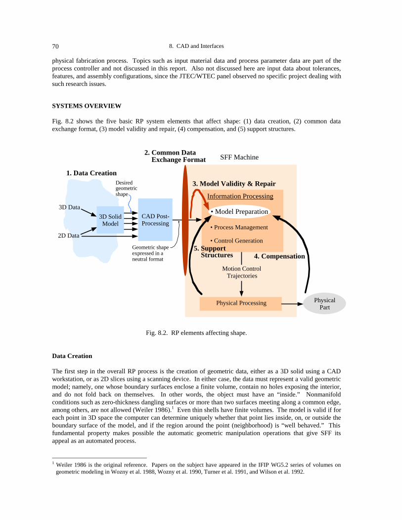
8. CAD and Interfaces70
physical fabrication process. Topics such as input material data and process parameter data are part of theprocess controller and not discussed in this report. Also not discussed here are input data about tolerances,features, and assembly configurations, since the JTEC/WTEC panel observed no specific project dealing withsuch research issues.
SYSTEMS OVERVIEW
Fig. 8.2 shows the five basic RP system elements that affect shape: (1) data creation, (2) common dataexchange format, (3) model validity and repair, (4) compensation, and (5) support structures.
4. Compensation5. Support Structures
3. Model Validity & Repair
2. Common Data Exchange Format
1. Data Creation
3D Data
2D Data
3D SolidModel
CAD Post-Processing
Motion ControlTrajectories
Physical Processing PhysicalPart
Desiredgeometricshape
SFF Machine
Information Processing
• Model Preparation
• Process Management
• Control GenerationGeometric shapeexpressed in aneutral format
Fig. 8.2. RP elements affecting shape.
Data Creation
The first step in the overall RP process is the creation of geometric data, either as a 3D solid using a CADworkstation, or as 2D slices using a scanning device. In either case, the data must represent a valid geometricmodel; namely, one whose boundary surfaces enclose a finite volume, contain no holes exposing the interior,and do not fold back on themselves. In other words, the object must have an “inside.” Nonmanifoldconditions such as zero-thickness dangling surfaces or more than two surfaces meeting along a common edge,among others, are not allowed (Weiler 1986).1 Even thin shells have finite volumes. The model is valid if foreach point in 3D space the computer can determine uniquely whether that point lies inside, on, or outside theboundary surface of the model, and if the region around the point (neighborhood) is “well behaved.” Thisfundamental property makes possible the automatic geometric manipulation operations that give SFF itsappeal as an automated process.
1 Weiler 1986 is the original reference. Papers on the subject have appeared in the IFIP WG5.2 series of volumes on
geometric modeling in Wozny et al. 1988, Wozny et al. 1990, Turner et al. 1991, and Wilson et al. 1992.

Michael J. Wozny 71
If 2D contour data are sent directly to the SFF machine, the information implicit in the description must besufficient to stitch together a valid 3D volume.
Common Data Exchange Format
For reasons of competitiveness, targeted markets, and performance, CAD systems utilize a variety ofgeometric mathematical forms and data formats. SFF machine vendors accommodate this variety byrequiring that all external input geometric models be expressed in a neutral format. CAD vendors areresponsible for providing CAD post-processors that translate their internal CAD representations to thiscommon format.
Model Validity and Repair
To be more precise, CAD post-processors actually approximate the vendors’ internal CAD geometric forms(e.g., B-splines) with a simplified mathematical form (triangles), which in turn is expressed in a specified dataformat: STL. Unfortunately, this approximating operation, if not done precisely, sometimes introducesundesirable geometric anomalies, such as holes or overlapping portions in the boundary surface.Consequently, most SFF machines have software to check the input model to ensure it is a valid solid, that is,it is a well-behaved, closed, and bounded model with a finite interior. If this is not the case, then capabilitiesare needed to repair the model.
Given a valid model, a series of geometric operations must be performed on the model (model preparation) toensure that the physical part will meet the input specifications. For example, the model needs to be orientedand scaled for the SFF machine workspace. The orientation depends on factors relating to surface quality,build time, support structures, downstream processing characteristics (shrinkage, curling, distortion, resinflow), and part tolerance, among others (Frank and Fadel 1994; Thompson and Crawford 1995). The nesting(Beascoechea 1995, 1996) of many parts in a single build chamber and the building of assembliesconcurrently are also considerations.
Compensation
The model shape may need to be altered to compensate for anticipated downstream physical anomaliesintroduced during fabrication, such as shrinkage, warpage, curl, and deformation. Most compensation todayis coarse and usually left to an operator’s intuition, gained by trial and error. The status of predictive analyticmodels is discussed later.
Support Structures
Support structures are needed in liquid-based processes to prop up overhanging portions of the 3D part, toattach the part to the workspace platform, and to internally buttress hollow parts. Parts and supports mayneed drain holes. Support locations for overhangs can be determined by checking the direction of surfacenormals and by z-axis projections of the model. Software exists to automatically generate support structuresthat attempt to use the least possible amount of material. Powder- and sheet-based processes use thesurrounding unprocessed material for support. Even in these latter processes, the Japanese would like toshorten the time required to remove unprocessed support material and clean the part to high surface quality.The cost of data preparation and post-processing can amount to two-thirds of the total cost of building a part(Dolenc and Mäkelä 1995).
For very precise parts with many thin protrusions, the compensation and support structure generationoperations may need to be iterated, because the support may distort the previously compensated part.
To obtain the necessary motion control trajectories to drive the actual solidification mechanism, the preparedgeometric model is sliced into layers of possible different thicknesses, and the slices are scanned into lines (ifrequired), mimicking in reverse the layer-to-layer physical building process (Rock 1991; Dolenc and Mäkelä

8. CAD and Interfaces72
1994; Suh and Wozny 1994). The scanned lines determine when a laser beam or some other solidifying agentis turned on or off. The layer thickness determines the amount to raise or lower the part and/or the containerfor recoating.
Using a manufacturing interpretation, Otto et al. (1995) categorize SFF software as the following types: (1)design (original part); (2) computer-aided process planning (part orientation, scaling, nesting, support design,compensation); and (3) computer-aided manufacturing programming (slicing, commands, and controls).
Ultimately, more sophisticated control strategies based on process sensor feedback loops are desirable, butthis is still a topic of research.
MAKING THE TRANSITION TO 3D SOLIDS
3D solid modeling is a relatively new concept to design and manufacturing — less than 30 years old. Itswidespread use in practice is even more recent, made possible by the large increases of the past 15 years inthe information processing power-to-cost ratio. On the other hand, engineering drawing using paper andpencil has evolved over 150 years. Although designers have migrated to solid modeling because analysis ismore easily handled, manufacturing engineers by and large still rely on drawings. The reason is morecomplex than that it requires a pro forma change in the way engineers view parts. An engineering drawing isa sophisticated language for building things and contains many nongeometric elements like tolerances, notes,and procedures that are meaningful to production. A solid model is simply a geometric representation ofshape.
It is therefore not surprising to find manufacturing-oriented companies, both large and small, changing onlyslowly to 3D solid modeling. The JTEC/WTEC panel found this to be particularly true in Japan, where useof 3D solids was estimated to be between 3% and 20%. Whatever the actual percentages, it is apparent that asizable number of RP users in Japan are not utilizing 3D solids at present. On the other hand, solid modelingfor RP is used widely in Europe, but still not as extensively as in the United States, where the solid model isseen as a key element in the next-generation design and manufacturing data representation that will supersededrawings, because it will be able to support automated processes.
The reason for the perceived slow adoption of 3D solids in Japan is not entirely clear. One answer may bethat the panel did not see a suitable cross-section of activity in large user companies because their RPtechnology was employed in the development of new proprietary products. Another reason may be that SFFis still too embryonic and relatively imprecise to attract serious attention across a large segment of Japaneseindustry. The current benefits of RP technology are perhaps perceived to be too small when compared withthe fast turnaround and high quality achieved by Japanese NC (numeric control) machining technology, whichis the best in the world. NC parts are produced directly from 2D drawings today.
Rapid prototyping will come into its own when the industry goes beyond making parts faster and startsproducing parts not possible by any other means. Sachs et al. (1995) give a relevant example dealing with thecreation of cooling channels that conform to the shape of the injection molding tooling, as opposed to thetraditionally machined straight channels. The conformal channels give precise temperature control of themolding cavity throughout the process cycle and reduce the part production cycle time.
It is a significant problem in Japan that most 2D part drawings must be recreated with 3D data beforeproceeding with RP, since much of this work is done manually.
Table 8.1 lists comments concerning this issue that the JTEC/WTEC panel collected from various Japanesehosts, primarily at the service bureaus. When the JTEC/WTEC team mentioned such comments to MITIrepresentatives, the response was that they recognize that this is a problem and they would like to see change,but there are no programs specifically aimed at accelerating the acceptance of 3D solid modeling. Severalhosts noted, however, that this and other RP topics may be addressed within the large supplementary budget

Michael J. Wozny 73
programs recently enacted by the Japanese government, with the most likely candidate being a major CALS(Commerce at Light Speed) program dealing with information integration in manufacturing.
Table 8.11995 Company Estimates of 3D Solid Modeling Use in Japan
RP COMPANY ORSERVICE BUREAU USE OF 2D VERSUS 3D
Tokuda Industries 80% of customers provide 2D CAD files that must be recreated in 3D
INCS, Inc. 90% of customers provide CAD files: - 55% 3D data (not necessarily solids) - 35% drawings - 10% othersIn 1993, creating/recreating 3D data represented 50% of totalproduction time
Kyoden Co. In 1993, 100% of work had to be converted from 2D to 3DIn 1995, 70% of customers submitted 2D filesBy 2000, expect 50% of small companies and 100% of big companiesto use 3D
Shonan Design Co. 50% of its work done on 2D CADAM; 20% on Pro/Engineer;30% on CATIA
The panel’s hosts also predicted dramatic changes in the future. They relate that Japanese industry hasrealized the strategic value of 3D solids; at the time of the JTEC/WTEC visit to Japan, plans were already inplace to transition to 3D CAD, with large companies expected to begin the shift within two years.
Few comments surfaced from the European site visits that expressed concern about the issue of 2D drawingversus 3D solid modeling. Instead, the issues in Europe seem to be related to cost and ease of use.
MAKING 3D SOLIDS-CREATION EASIER
Comments from users in Japanese companies, such as those in Table 8.2, express concern that 3D solids-creation takes too long and needs to be simplified, both from the viewpoint of migration from 2D, as well asoriginal creation in 3D. Issues include training and reduction of learning times; software aids for simplifying3D use; software aids for easing the transition from 2D; company-wide integration of 3D; and targetedapplications, especially those involving small companies.
As Table 8.2 shows, Japanese organizations and researchers are taking a variety of approaches in addressingthese issues. Hino Motors reduced learning times by simply changing its CAD system. Nakamura PatternMaking Company adapted easily to an RP system based on wood, a material with which its pattern makershave a lot of experience. In fact, company owners hold that effective use of SFF is not possible withoutprofound understanding of the material. Meiko developed a CAD system, JCAD3, intended only for jewelrydesign, that is easy enough to use that the jewelry industry’s designers should be able to use it with little CADexperience. D-MEC plans to develop software to help users convert 2D drawings to 3D solids. No systemwill do this automatically, since drawings are sometimes incomplete or ambiguous, lack associativity amongviews, or do not follow geometrically precise conventions in generating auxiliary views.
Researchers are also addressing the ease-of-use issue. Professor Fukuda at Tokyo Metropolitan Institute ofTechnology is developing tools that will create and modify models more intuitively at early design stages. Hesays his system, which can build 3D models from 2D slices, is very easy to use. Professor Fukuda is also

8. CAD and Interfaces74
working on a virtual reality (VR) tool for facilitating design modification. His goal is to have a designerproduce a prototype part, then be able to manipulate it with data gloves (Fukuda would like to use a softputty-like material), and feed back those changes immediately to the CAD environment via sensors. Touchcues are an important designer feedback mechanism. Data gloves with force feedback will play an importantrole in design in the future.
Table 8.2Japanese Views on Using 3D Solids
COMPANY/INSTITUTE COMMENTS
Olympus Optical Co. Preparing 3D CAD data takes a major portion of timeConstitutes a major barrier to use of rapid prototyping
Omron Limited 3D CAD experience is a major barrierNeeds to be easier for design and tool engineers to use
Toyota Motor Corp. Preparing data for RP takes too long
Shonan Design Co. “Section” thinking in large companies: designers accept 3D CAD,but tooling engineers use 2D drawings
5% of companies have 3D CAD/CAM common data
Hino Motors Replaced its CAD system to reduce learning timesWidespread use of 3D CAD in company in 2-3 years
Meiko Co. Produces and markets its own easy-to-use CAD systemJewelry industry has little experience with CAD
Nakamura Pattern Making Co. Adopted 3D CAD easily due to long experience building 3D patterns
D-MEC Designers need help to migrate from 2D to 3D systems
Tokyo Metropolitan Instituteof Technology (Prof. Fukuda)
Need CAD systems that support intuition at early design stagesVR coupled with CAD and RP supports intuition and facilitates
modification
Although better analytical models will enable greater use of simulation and VR, physical prototyping will notvanish. In fact, a physically prototyped part of the future may contain a specially instrumented computer-sensing system housed in the geometric package. Clearly, aspects of today’s physical prototyping will evolveinto the next-generation manufacturing machines.
INTERFACE FORMATS
The formats used by SFF machines to accept external geometry consist of a mathematical representation ofthe geometry and a data description in a file.
Mathematical Representation
The boundary surface of a solid can be expressed in a variety of geometric forms: Bezier, nonuniform rationalB-spline (NURBS), Coons patch, Gordon patch, planar patch, cyclide, and other blending surfaces, loftingsurfaces defined by specific procedures, and implicit forms, to name just a few. For each form it accepts, theSFF machine must maintain a separate set of geometry manipulation routines or utilities, even in cases wherethe form is a special case of another, if speed is an issue. (There is a time penalty incurred when slicingsimple triangles with a generalized complex slicing algorithm designed for NURBS surfaces.) This meansthat many of the CAD geometry utilities that already exist in the different vendor CAD workstations must be

Michael J. Wozny 75
duplicated in the SFF machine. The need for duplication is further exacerbated by the fact that CAD vendorsgenerally do not make public all aspects of their internal geometries.
The ideal compromise, and the one often followed today, is to have SFF machines accept one commongeometric form — thus needing only one set of slicing and other geometric utilities — and shift to the CADvendors the burden of translating their internal, sometimes proprietary, math forms to this accepted commonform. Conceptually, the problem reduces to one of approximating by a single geometric form all othergeometric math forms, as well as their intersection curves, trim curves, and blends — hardly an optimal solution.
Triangular Facets
What “common” math form to use? One choice is the most general math form possible, which will bediscussed later in the section on the STEP standard. The other extreme is to choose the simplest of all thegeometric surface forms, the triangular element. (Some argue that slices are a simpler and more flexiblerepresentation.) The triangular approximation consists of sampling the original surface and connecting thesurface sample points with triangles. The simplicity of the triangle geometry is offset by the huge numbers ofvery small triangles needed for a good approximation, and the opportunity for numerical and otherapproximation errors (some triangles may degenerate to lines).
The process of approximating a surface by triangular facets, sometimes referred to as tessellation, is usedextensively in computer graphics, where special integrated circuit chips have been designed to perform thisfunction. Triangular approximations of smooth surfaces work well for color rendering and shading ongraphic displays, because the surface is continually subdivided until the triangles are smaller than a screenpixel, and then each triangle is color-blended across its edges to give the appearance of a smooth shadedsurface. Unfortunately, slope discontinuity across the edges of adjacent triangles cannot be disguised soeasily in physical parts, and this has downstream processing ramifications.
Data Representation
The simplest scheme for a data format is to represent the solid as a sequence of surfaces. A surface isrepresented as a sequence of triangle elements, with no regard to order or topology. A triangle element isrepresented as a sequence of its three vertices and its outward (from the surface)-pointing normal vector,defined according to the right hand rule by the order of the vertex sequence (Fig. 8.3). This representation,along with its data types, delimiters, and other file information is called the STL format, introduced originallyby 3D Systems, Inc., in 1988. It is the de facto standard for transferring solid geometric models to SFFmachines.
CAD Workstation
n
(x1,y
1,z
1)
(x2,y
2,z
2)
(x3,y
3,z
3)
Common Format (STL)
3D SolidModelCreation
CAD Post-Processing
SFF Machine
• Geometry (triangular facets)
• Data Format (normal, verticies)
Information Processing
Control
Fig. 8.3. Geometry form used in STL format.

8. CAD and Interfaces76
Although many SFF machine vendors offer their own formats (summarized in Fig. 8.4 on p. 80), they allaccept STL. Since 3D Systems was the first and remains today the major vendor in the marketplace, itsformat will continue to dominate. The small enhancements in format offered by others will not tilt thebalance. Based on the evolution of CAD formats, the key enabler of change will be a motivated and vocaluser community.
CAD Solid Modelers Accepted by SFF Machines
Table 8.3 lists the CAD modelers being used at the sites visited by the JTEC/WTEC panel. As one wouldexpect, many of the solid modelers popular in the United States are also popular in Europe and Japan. Thereason is simply that U.S. CAD vendors dominate the commercial market. Whereas many U.S. companiesnow use vendor-supplied CAD systems, Japanese companies continue to develop proprietary systems (orportions of systems). Most European companies use commercial modelers, except for some large companieslike Daimler Benz.
Table 8.3CAD Solid Modelers That Interface with SFF Machines
CAD Solid Modeler * Company
Pro/EngineerCATIACADDSCADAMI/EMS => Solid EdgeUnigraphics (parasolid)ME30 & PE/Solid DesignerAutoCADDesignBaseFresdamCaelumI-DEASCamand (surface)CAM ToolMacSurf (surface)ZYRCODUCTEuklid
Parametric TechnologyDassault SystèmesComputer VisionDassault SystèmesIntergraphEDSHewlett-PackardAutodeskRicohSonyToyotaStructural Dynamics Research Corp.Camax Manufacturing Technologies
Denken and AutostradeDaimler BenzDelcam (UK)Swiss
* Most names are registered trademarks
The desire to develop proprietary CAD and RP software is reminiscent of the “reincarnation of the wheel”phenomenon, which is characteristic of fast-moving fields. It was certainly true in commercial CAD duringits rapid growth in the late 1970s and early 1980s. CAD may be used as an example to illustrate thedynamics. Initially, large technically based companies developed their own internal CAD systems becausetheir specific internal needs were not being met by the emerging commercial vendors. Using their formidablestate-of-the-art internal expertise in applications and computers, these companies were able to create CADenvironments that not only went well beyond the capabilities of commercial systems, but also were tuned totheir internal needs. However, when these CAD systems became operational, the general tendency was toscale back further enhancement because, after all, the system is only a means to an end and not the mainproduct of the company. Meanwhile, the commercial CAD vendors continued to innovate and ultimately

Michael J. Wozny 77
surpassed the capabilities of the user companies, causing senior management to abandon aging internalsystems for state-of-the-art commercial systems.
This cycle continues to repeat itself. As the CAD vendor’s application base continues to grow and diversify,its support has to harmonize the needs of a larger application base. Since the vendor can no longer dedicatesufficient resources to company-specific enhancements and meet the company’s rigid time schedules, thecompany launches a new internal development effort to create its next-generation CAD environment aimedspecifically at its current needs.
The trend in rapid product development today is toward a broad system of many integrated functions. CADis but one cog in this big product development wheel. Consequently, enhancements in CAD are judged not inisolation, but in terms of their effect on overall system functionality, throughput, and stability. A newgeometric engine may not be useful if it means redeveloping existing geometric utilities, scrapping thedatabase system, and launching a major training program. Ultimately, such considerations will be necessaryfor those RP systems used in engineering and manufacturing.
Today, virtually every commercial CAD vendor provides a CAD post-processor for translating internallyrepresented CAD solid models into faceted solid models for SFF machines. Additional modelers that provideSTL include Aries Concept Solids from Aries Technologies; Bravo3 from Applicon; CADKEY from Cadkey,Inc.; and the French modeler EUCLID from Matra Datavision. A number of PC-based 3D modelersoriginally developed for 3D graphics applications now offer STL output capability.
Standard for the Exchange of Product Model Data (STEP)
Although many agree that the STL format leaves much to be desired, there is no unanimity on its replacement(Dolenc and Mäkelä 1995; Jamieson and Hacker 1995). Since there is no single all-encompassing generalmath form that includes all other practical geometric surfaces as special cases, then it makes sense to focus onthose math forms that support a large application base. The evolving STEP standard for the exchange ofproduct data, based on NURBS geometry, is the most promising candidate, because of its growing acceptanceand use in engineering and manufacturing applications.
NURBS geometry was originally promoted and developed by the aircraft industry, specifically by Boeing,because conic sections, which are very important in the aerodynamic design of airplanes, are representedexactly by NURBS. With its great flexibility and power, however, NURBS has disadvantages as well: it ismore difficult to master; pathological and practically nonrealizable surfaces are easily generated; and sometheoretical aspects are still thorny. Regardless, NURBS has caught on and is rapidly becoming the mostwidely used surface form, including the computer graphics standard, PHIGS (Programmers HierarchicalInteractive Graphics System).
In the United States, the CAD community has been developing standards for exchanging data among CADsystems since 1979 when Boeing, GE, and NIST (National Institute of Standards and Technology, thenknown as the National Bureau of Standards) joined forces to lead a national effort to develop a neutral fileformat for representing engineering drawings. The effort led ultimately to IGES (Initial Graphics ExchangeSpecification), which became a U.S. national standard in 1981. See the U.S. Product Data Association(http://elib.cme.nist.gov/nipde/) and STEP Tools, Inc. (http://www.steptools.coml) web sites for details. Thecurrent version, IGES 5.2 transcends its original manifestation as a standard for exchanging 2D graphicaldrawings and includes 3D surfaces and solids. Similar efforts in Europe led to the German DIN 66301standard, VDA-FS (Verband de Automobilindustrie 1987, http://www.serv.net/tms/vda_over.html), and theFrench AFNOR Z68-300 standard, SET (Standard d’Échange et de Transfert).

8. CAD and Interfaces78
All of these CAD standards efforts are now being superseded by STEP,2 a much more extensive dataexchange standard that will eventually extend beyond product data and include process and resource data.The first phase of STEP was approved in late 1994 as international standard ISO 10303 by the InternationalStandards Organization (ISO) (http://www.igd.fhg.de/www/igd-a2/hyperstep/iso-10303/gen.htn andhttp://www.scra.org/pdesinc.html). Most CAD vendors are committed to supporting STEP. (One can thinkof IGES as specifying a neutral flat file format, while STEP specifies the associativities of a neutraldatabase.) The STEP standard provides extensibility to many application domains through a structure called“application protocols.” Each application domain has its own application protocol, with substantial sharingof common core functions.
There is strong interest in developing a STEP application protocol for exchanging CAD data with SFFmachines. In Japan, Professors Kishinami and Kimura (http://www.cim.pe.u-tokyo.ac.jp/index-j.html), whohave interests in systems aspects of rapid prototyping, are also deeply involved in STEP activities.Preliminary work on a STEP application protocol for SFF machines was begun in 1993 as part of the RapidProduct Realization project in the international Intelligent Manufacturing Systems (IMS) program, led byUnited Technologies in the United States, Daimler Benz in Germany, and other companies in other countries.See IMS Test Case #6 1994 (January and June), and Aubin (1994). SFF standards continue to be promotedin the United States by the Rapid Prototyping Association of the Society of Manufacturing Engineers (http://www.sme.org/memb/rpa.html), NIST, and the DOE Sandia National Labs. Gilman and Rock (1995) propose tointegrate more closely into the design process using STEP as the vehicle of integration.
2D Slice Data
For many reasons, 2D slice data is a viable format. Some believe a 2D contour representation is more basicthan a 3D solid model. The founders of one German company, Fockele and Schwarze (1994), believe thatthe 2D contour representation allows their company to build bigger and more precise parts. Others suggest itis easier to work with. Management of the Belgium software company Materialise (http://www.materialise.com/technic/contour.html) takes this position: “At the primary level, each RP machine operates onthe basis of stacks of 2-dimensional drawings. 2D contour software enables the user to work efficiently withthis data stream, thus solving special problems and enabling special applications. ... By tackling the interfacingproblem at the contour level, contour software is able to solve all problems with bad STL files.” Finally andmost importantly, 2D data from medical scan devices represent the tip of the iceberg for a vast biomedicalfield that promises to be a key application area for RP.
European activity in 2D formats is motivated in good measure by biomedical applications (implants,operation planning), but also by reverse engineering applications utilizing laser and other scanning devices. 2 The U.S. Product Data Association (US PRO) has been granted distribution rights by the American National StandardsInstitute (ANSI) to reprint, market, sell, and distribute Draft International Standards (DIS) and International Standards(IS) of ISO 10303 and 13584 within the United States (US PRO; P.O. Box 3310; Gaithersburg, MD 20885; FAX 301-926-8730). Standards of interest here are as follows:
A. ANS US PRO/IPO-100-1993. IGES 5.2, Initial Graphics Exchange Specification, Nov. 1993.B. ANS US PRO/IPO-200-1994. Product Data Exchange using STEP (PDES): Initial release includes parts (whichcan be ordered separately)
1. Overview and Fundamental Principles11. The EXPRESS language Reference Manual21. Clear Text Encoding of the Physical File Exchange Structure31. Conformance Testing Methodology and Framework: General Concepts41. Integrated Generic Resources: Fundamentals of Product Description and Support42. Integrated Generic Resources: Geometric and Topological Representation43. Integrated Generic Resources: Representation Structures44. Integrated Generic Resources: Product Structure Configuration46. Integrated Generic Resources: Visual Presentation101. Integrated Application Resources: Draughting201. Application Protocol: Explicit Draughting203. Application Protocol: Configuration Controlled Design

Michael J. Wozny 79
Technical interests range from general boundary curve forms (beyond polylines) to more flexible filestructures. Rather than tessellate a surface and then slice the tessellated surface, why not slice the originalsurface (direct slicing) and then approximate the contour curves with polylines? Some feel this processreduces error, produces better surfaces, and results in smaller files (Ganesan and Fadel 1994; Vuyyuru et al.1994; and Jamieson and Hacker 1995). German companies Fockele and Schwarze (1994) and CENIT GmbH(http://www.catia.ibm.com/html/clog407.html) use direct slicing.
The requirements for a flexible and vendor-independent format led to the development of the Common LayerInterface (CLI) format by a consortium of European countries organized under the EEC research programBasic Research in Industrial Technologies for Europe/European Research on Advanced Materials (BRITEEuRAM 1994). The goal of CLI was a flexible format that applies to all RP technologies, permits user-specific data (such as patient orientation in CT scans), and allows data transfer among a wide range ofapplications. User-specific data is included in the header section. The geometry section consists of anordered (ascending) sequence of layers and their respective heights. The boundaries (outside, plus holes) ofeach layer are defined by closed polylines, with the “inside” or “material” side always on the left as thepolyline coordinates are traversed. CLI supports both ASCII and BIN formats (http://www.cranfield.ac.uk/aero/rapid/CLI/cli_v20.html). Its first major application area is medical scan data.
The CLI format is now being supported by the European Action on Rapid Prototyping (EARP). EOS’s(Electro-Optical Systems) layer data exchange software in EOSOFT is based on the CLI format. Materialiseoffers a range of software for RP, including software to generate parts directly from CT (computedtomography) and MRI (magnetic resonance interferometry) scans. Materialise’s MIMICS softwareinterpolates data from medical scanners, as described later in the section on RP Software.
There is still some concern that CLI (also the 3D Systems slice format, SLC) is still not flexible enough to bea standard (Dolenc and Mäkelä 1995). CLI seems to be biased toward fluid-based processes and dominatedby medical scan data applications. An experimental data exchange format proposed by Dolenc and Mäkelä(1992), called Layer Exchange ASCII Format (LEAF), addresses these and other shortcomings such asflexibility, loss of information, lack of user control, ambiguity, impractical assumptions, and processdependency. LEAF is an experimental tool for researchers to promote standardization and is being developedfurther by researchers at the Fraunhofer Institute for Manufacturing Engineering and Automation in Stuttgart.
Daimler Benz’ ZYRCO CAD software is compatible with CLI and STL, but the company prefers STL.Fockele and Schwarze, on the other hand, builds 3D parts from contours.
The Japanese are using the Hewlett-Packard Graphics Language (HPGL) format for representing 2D slicedata. HPGL is the de facto standard for 2D plotting, where the data is represented in a vector format: startpoint coordinates, end point coordinates, pen up/down. INCS is developing software that interpolates andsmoothes the CT slice data into an STL model for use in maxial facial reconstruction surgery.
SLC is 3D Systems’ contour data format for importing external slice data, and SLI is the company’s machine-specific 2D format for the vector commands that control the laser beam.
The Cubital Facet List (CFL) format is based on a polygon-based representation consisting of n-sidedpolygons that can have multiple holes (Cubital, Ltd. n.d.). The format avoids redundant vertex informationand maintains topological consistency. CFL consists of a header and fields containing the total number ofvertices (points) and facets in the object, a numbered sequence of vertex coordinates, numbered facets (withnumber of holes), and pointers back to their respective vertices. An example is given in Fadel and Kirschman(1995).
Fig. 8.4 summarizes the various 2D and 3D formats being used today in Europe and Japan.

8. CAD and Interfaces80
Virtual Reality Modeling Language (VRML)
The Bremen Institute for Industrial Technology and Applied Work Science (BIBA) has opened a web dialogon replacing the STL format with the Virtual Reality Modeling Language (VRML) format(http://www.biba.uni-bremen.de/users/bau/s2v.html). VRML is an evolving standard for describingmultiparticipant interactive three-dimensional scenes networked via the global Internet and hyperlinked withthe World Wide Web (http://sdsc.edu/vrml/ and http://vrml.wired.com/). VRML is based on the OpenInventor ASCII File Format from Silicon Graphics, Inc., which supports descriptions of computer graphics3D scenes with polygonally rendered objects, lighting, materials, ambient properties, and realism effects(http://vrml.sgi.com/moving-worlds/). VRML, in the near term, extends this base to support multiusernetwork interaction, animation, and scripting.
Information Processing3D FormatsInput Data
STL de factoStandard for 3D
No SingleWidely AcceptedFormat for 2D
HPGL (HP), CLI (EOS), LEAF (proposed)
SLC (3D Systems), SLI (3D Systems internal)
F&S (Fockele und Schwarze), 2D Custom
STL (3D Systems)
IGES(CAD), VDA(DIN, Autos) => STEP (ISO)
RPI (proposed), 3D Custom
3D Solid Models3D Digitizer Data3D Mesh Data
2D Scan Data2D Slice (Contour) Data
DFX (AutoDesk), CFL (Cubital)
SLC (Stratasys), BIN (Sanders)
2D Formats
Fig. 8.4. Data exchange formats for SFF machines.
Advocates of abandoning STL point out that VRML deals with the bigger picture: the 3D extension of theWorld Wide Web, the future 3D telecommunication and networking standard, which could also become thestandard interface for all “3D hardprint” tasks, with formats for storing and viewing with a 3D web browserbefore printing. Advocates claim that the adoption of VRML would make RP more accessible globally.VRML 1.0 (http://vrml.wired.com/vrml.tech/vrml10-3.html) is based on facets, so it accommodates STL filesas well as accommodating AutoCAD DXF and parts of IGES, among others.
Some RP research, for example, by Baily at the San Diego Supercomputer Center, deals with“telemanufacturing” issues (http://www.sdsc.edu/EnablingTech/Visualization/TMF/tmf_intro.html).
VRML will work well for describing the network-based objects in a 3D scene involving interaction,animation, or simulation, because VRML is a direct extension of interactive computer graphics. Truenetwork interaction and seamlessness will ultimately require Java-like concepts. VRML today provides ageometry-viewing capability but has not addressed engineering needs such as the creation of very complexgeometry and the ability to use it in other analyses. (Future versions of VRML are expected to includeNURBS, but today, such geometry creates a heavy processing load.) This is where STEP and otherengineering network projects, like National Industrial Information Infrastructure Protocols
Michael J. Wozny 81
(http://www.niiip.org/) or Computer-Aided Manufacturing Network (CAMnet) (http://ce-toolkit.crd.ge.com/camnet/conops/conops_5.html) in the United States play an important role for engineering and manufacturing.
The engineering and manufacturing applications segment of RP will not be the major segment of the futureRP market, and not necessarily the primary technology base for the mass market. In the past two decades,much of the innovative computer technology (PCs, RISC architectures, small high-density disks) andinterfaces (Xerox PARC, Apple) that made computer technology accessible by the masses evolved fromneeds at the grass roots (even computer games), not from the needs of large mainframe operations. The samewill be true for future 3D Fax technology — it will have to be stand-alone, desktop, cheap, and universal.
Future RP systems for engineering and manufacturing applications will be specialized and at the cutting edgeof processing sophistication, because these systems will replace existing manufacturing machines that makefunctional parts.
Demarcation between SFF Machine Functions and External Geometry Creation Functions
Duplicating CAD geometry manipulating functions in SFF machines preserves the functional independence ofthe machines from the CAD workstations generating the input data. Model manipulating operations that dealwith SFF machine-specific functions, such as orientation, scaling, nesting, compensation, and slicing, need tobe dealt with locally by an operator who understands the idiosyncrasies of the SFF process and the propertiesof the raw material. If, for example, a prototyped part warps or shrinks more than anticipated due to anunforeseen processing imperfection, the operator must have the option to compensate locally and makeanother run without having to go back to the CAD environment. The need to understand in detail theprocessing and material properties is even more important when producing functional parts (metals, ceramics,etc.).
If changes in the original design need to be iterated with a series of interim prototypes, then ideally, suchincremental changes should retain as much of the originally processed data as possible.
As the RP market ultimately subdivides into focused segments, that portion dealing with producing form partsfor viewing should achieve totally automated operation.
MODEL PREPARATION
Model preparation begins with validation of the input model to ensure it is a solid; if it is not, it must berepaired. (Models are corrupted either by designer misunderstandings or inadequate CAD post-processing, asdescribed below.) The valid model is then scaled and oriented with respect to the build chamber, taking intoaccount build direction, build time, surface quality, and potential distortion. Many models may either bemerged into a one-build assembly or nested for efficient utilization of the machine and material. The modelsmay need to be compensated to account for downstream shrinkage or deformation. Finally, the supportingstructures for overhanging part geometry as well as internal supports are added, if the process requires them.Such structures are often generated automatically in a separate file that is merged with the model file prior toslicing. The generation of control signals starts with slicing the model(s) and then scanning each slice intolines to determine the peripheral contour boundary needed to control the solidification process.
Model preparation consists of three steps: (1) validation and repair; (2) compensation; and (3) supportstructure generation, as illustrated in Fig. 8.5.
Model Validation and Repair
Any sampling process can introduce geometrical anomalies. For example, if spatial sampling is done toogrossly, then small local features and local surface curvatures are lost irrevocably, or if two intersectingsurfaces have significant differences in curvature, then problems can occur along their intersection curve.
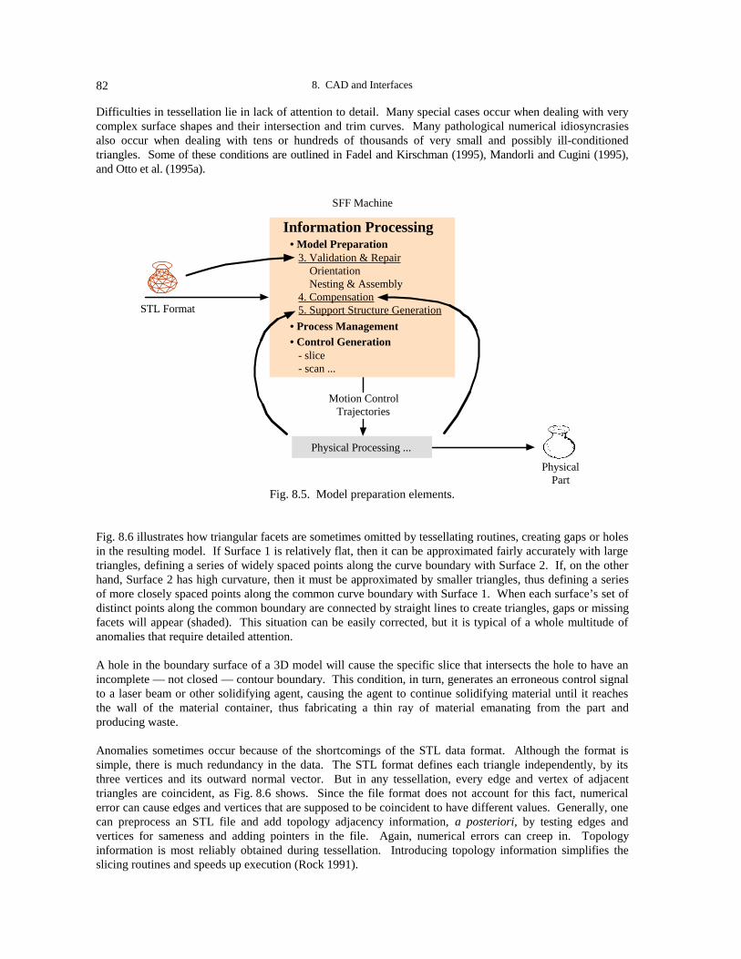
8. CAD and Interfaces82
Difficulties in tessellation lie in lack of attention to detail. Many special cases occur when dealing with verycomplex surface shapes and their intersection and trim curves. Many pathological numerical idiosyncrasiesalso occur when dealing with tens or hundreds of thousands of very small and possibly ill-conditionedtriangles. Some of these conditions are outlined in Fadel and Kirschman (1995), Mandorli and Cugini (1995),and Otto et al. (1995a).
STL Format
SFF Machine
Information Processing• Model Preparation 3. Validation & Repair Orientation Nesting & Assembly 4. Compensation 5. Support Structure Generation
Motion ControlTrajectories
Physical Processing ...
PhysicalPart
• Process Management• Control Generation - slice - scan ...
Fig. 8.5. Model preparation elements.
Fig. 8.6 illustrates how triangular facets are sometimes omitted by tessellating routines, creating gaps or holesin the resulting model. If Surface 1 is relatively flat, then it can be approximated fairly accurately with largetriangles, defining a series of widely spaced points along the curve boundary with Surface 2. If, on the otherhand, Surface 2 has high curvature, then it must be approximated by smaller triangles, thus defining a seriesof more closely spaced points along the common curve boundary with Surface 1. When each surface’s set ofdistinct points along the common boundary are connected by straight lines to create triangles, gaps or missingfacets will appear (shaded). This situation can be easily corrected, but it is typical of a whole multitude ofanomalies that require detailed attention.
A hole in the boundary surface of a 3D model will cause the specific slice that intersects the hole to have anincomplete — not closed — contour boundary. This condition, in turn, generates an erroneous control signalto a laser beam or other solidifying agent, causing the agent to continue solidifying material until it reachesthe wall of the material container, thus fabricating a thin ray of material emanating from the part andproducing waste.
Anomalies sometimes occur because of the shortcomings of the STL data format. Although the format issimple, there is much redundancy in the data. The STL format defines each triangle independently, by itsthree vertices and its outward normal vector. But in any tessellation, every edge and vertex of adjacenttriangles are coincident, as Fig. 8.6 shows. Since the file format does not account for this fact, numericalerror can cause edges and vertices that are supposed to be coincident to have different values. Generally, onecan preprocess an STL file and add topology adjacency information, a posteriori, by testing edges andvertices for sameness and adding pointers in the file. Again, numerical errors can creep in. Topologyinformation is most reliably obtained during tessellation. Introducing topology information simplifies theslicing routines and speeds up execution (Rock 1991).
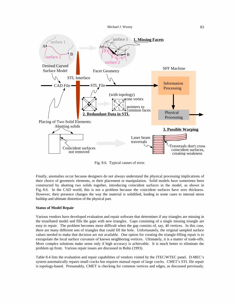
Michael J. Wozny 83
surface 1
surface 2
1. Missing Facets
A
B
SFF Machine
InformationProcessing
PhysicalProcessing
surface 1
surface 2
A
B
f1f2
f3
f4
(with topology)
pointers tocommon faces
one vertex
2. Redundant Data in STL
Abutting solids
Coincident surfacesnot removed
Laser beamtraversals
3. Possible Warping
Traversals don't cross coincident surfaces,creating weakness
Desired CurvedSurface Model
CAD File
Placing of Two Solid Elements:
Facet Geometry
STL File
STL Interface
Fig. 8.6. Typical causes of error.
Finally, anomalies occur because designers do not always understand the physical processing implications oftheir choice of geometric elements, or their placement or manipulation. Solid models have sometimes beenconstructed by abutting two solids together, introducing coincident surfaces in the model, as shown inFig. 8.6. In the CAD world, this is not a problem because the coincident surfaces have zero thickness.However, their presence changes the way the material is solidified, leading in some cases to internal stressbuildup and ultimate distortion of the physical part.
Status of Model Repair
Various vendors have developed evaluation and repair software that determines if any triangles are missing inthe tessellated model and fills the gaps with new triangles. Gaps consisting of a single missing triangle areeasy to repair. The problem becomes more difficult when the gap consists of, say, 40 vertices. In this case,there are many different sets of triangles that could fill the hole. Unfortunately, the original sampled surfacevalues needed to make that decision are not available. One option for creating the triangle-filling repair is toextrapolate the local surface curvature of known neighboring vertices. Ultimately, it is a matter of trade-offs.More complex solutions make sense only if high accuracy is achievable. It is much better to eliminate theproblem up front. Various repair issues are discussed in Bohn (1993).
Table 8.4 lists the evaluation and repair capabilities of vendors visited by the JTEC/WTEC panel. D-MEC’ssystem automatically repairs small cracks but requires manual repair of large cracks. CMET’s STL file repairis topology-based. Presumably, CMET is checking for common vertices and edges, as discussed previously.

8. CAD and Interfaces84
The Denken/Autostrade Solid Laser Plotter software displays damaged surfaces and has the capability forextensive slice manipulation.
Table 8.4Status of Model Repair
COMPANY/INSTITUTE COMMENTS
D-MEC Auto repair of small cracks, manual repair of large onesAuto thickness adjustment for 2½D models
CMET STL file repair is topology-based
Denken/Autostrade(Solid Laser Plotter)
Displays damaged surfacesExtensive slice manipulation
Cubital Solider Data Front End (DFE)Repairs STL files – cuts, patches, or trims facets, ...
Daimler Benz CAD support tools generate error-free STL models
In Europe, Cubital representatives maintain that their Solider Data Front End (DFE) system has extensivemodel manipulation capability and can repair everything: it can cut, patch, or trim facets. Daimler Benzattacked the problem up front, which is possible for an internal system, by creating its own CAD support toolsto generate error-free STL models.
Compensation
Since physical parts shrink and deform under processing, models are needed to anticipate and compensate forthese shape changes. Most users today follow a trial-and-error procedure, iterating through several trial runsbefore achieving the desired part. The JTEC/WTEC panel saw a number of studies underway, summarized inTable 8.5, that are aimed at replacing this intuitive process with one founded on formal analytical tools. Theunderlying difficulty in developing analytical tools is lack of detailed process understanding.
Table 8.5Status of Deformation Compensation
COMPANY/INSTITUTE COMMENTS
Tokyo University Simulates stress buildup and deformation
Denken /Autostrade Uses FEA to determine the optimal scanning strategies thatminimize distortion (for specific geometries)Models laser-polymer interaction & resultant stress-formation
Kira Compensates 1.5%-2% in z direction for effects of humidity(paper swelling)
IFAM (Bremen) Optimizes designs for stress using genetic algorithms
IKP (Stuttgart) Analyzes forces in multiple layers to gain betterunderstanding of the resulting warp and curl
Research is underway at the University of Tokyo to simulate stress buildup and the resulting deformation.Denken Engineering/Autostrade is considering using finite element analysis (FEA) to create optimal scanningstrategies that minimize distortion for specific geometries. This work requires the modeling of laser-polymer
Michael J. Wozny 85
interactions to determine the resultant stress formation. Kira simply compensates 1.5-2% in the z direction toaccount for the swelling of its paper due to humidity. Nakamura Pattern Making Company considers highquality and precision to be the most important requirements, even more important than price. In fact,Nakamura bought a more expensive SFF machine rather than risk compromising these requirements with aless expensive machine.
Projects dealing with part distortion are underway in Europe as well. At the Fraunhofer Institute for AppliedMaterials Research (IFAM), designs are being optimized for stress using genetic algorithms, and the Institutefor Polymer Testing and Polymer Science (IKP) at the University of Stuttgart is using finite elementtechniques to predict forces in multiple layers to better understand the resulting warp and curl.
Support Structures
Table 8.6 summarizes the current work that the JTEC/WTEC panel observed on development of supportstructures. The panel found that in Japan much of the software activity for generating support structures forRP parts is internal and proprietary. For example, CMET’s customers design supports manually. Whileengineers at CMET are aware of existing automatic support-generator software that may suffice (see nextsection), they have decided to develop their own.
Concerning European activity for support structures, panelists saw very efficient capabilities underdevelopment. The scientists at EOS are working on optimizing the amount of material used (mesh stylesupports) in their Skin and Core Support software. MAGICS software from Materialise allows the buildingof lattice-like support structures that constitute only 10% of the part’s resin volume and build time. Panelmembers understand that Laser 3D has some capability in designing support structures, but have no details.IKP is developing new hatching strategies for both sintering and stereolithography processes.
Table 8.6Status of Support Structure Development
COMPANY/INSTITUTE COMMENTS
CMET (Japan) Customers design supports manuallyInternal version generates supports automatically
Materialise N.V.(Belgium)
Lattice-like support structures require only 10% of resinvolume and build time
EOS (Germany) A mesh-style support is generated by Skin and Core Supportsoftware
Laser 3D (France) Has a capability
IKP (Stuttgart) Has new sintering and stereolithography hatching strategies
RP Software
Several independent software houses have emerged in Europe over the past few years to support the growingRP market. The software activity in Japan seems to be in the service bureaus, like the medical software beingdeveloped by INCS, although the Ricoh SolidDesign™ solid modeler is an excellent starting point fordeveloping an RP capability. The United States has many small RP software houses that cover all aspects ofthe market. Some software companies have extended their CAD and model creation capabilities, likeImageware in the United States. Others provide software for RP-specific operations like STL data viewing,data transfer, data models, or support generation, with the goal of independence from vendors. Materialise inEurope and Brock Rooney and Associates (1992) in the United States are typical of this latter category. Theestablishment of newer RP software companies, such as DeskArtes in Finland (http://www.deskartes.

8. CAD and Interfaces86
fi/rt.html), indicates that the market in Europe will continue its rapid growth. See Wohlers athttp://lamar.colostate.edu/~wohlers/ for market data.
Research institutes such as BIBA (http://www.biba.uni-bremen.de/groups/rp/rp_page.html) have alsodeveloped a variety of interfaces, from a VDA-to-STL translator to new software that combines the pointclouds from a multiviewed scanned object into a contoured model in the CLI layer format.
Software offerings of Materialise are representative of the excellent functionality available in Europe(http://www.materialise.com/). Materialise offers three major RP packages, whose specific capabilities areshown in Tables 8.7 and 8.8 and Fig. 8.7:
• MAGICS (visualization, measurement, manipulation, and support generation for STL files)
• Contour Tools (detects, visualizes and repairs defective contours; performs slicing, repair of bad STLfiles, and support-generation based on contours)
• CT-Modeler System (handles CT scan data for RP & CAD)
Table 8.7MAGICS Software from Materialise
Level* Features
1. MAGICS QM(Quotation Maker)
2. MAGICS RP(Rapid Prototyping)
3. MAGICS SG(Support Generation)
Visualization of STL filesView modes: wireframe, shading, triangle view, ...Visual detection of bad STL filesGeneration of 2D sections along x, y, and z axesMeasuring in 2D and 3DBasic manipulations: rotate, mirror, rescaleBuild time estimation
Advanced part manipulation: pick/place (workspace) and bottom plane (orientation)Text utility to label STL filesBuild time calculation optimizes machine productivityCutting of STL files, including non-straight cutting profilesPunching holes into STL files to overcome trapped volumes
Automatic and interactive support generationDifferent editing levels to customize supportsPerforated supports, allowing
• less resin consumption• faster building• easy removal• better draining
Part and support visualization in 3DFast direct slicing of supports with optimal scan pattern
* The full set of Level 2 features includes those of the previous level, namely, Level 1; the full set of Level 3 features includes those of the previous levels, namely, Level 2 and Level 1.
The CT-Modeler package provides a complete interface from a CT medical scanner to CAD systems or RPmachines, as shown in Fig. 8.7. MIMICS is the medical front end of the package, in which segmentation ofstructures is done using 3D selection and editing tools. A 3D color image is generated from slice data. C-SUP generates support structures. Perforated support structures build four times faster, consume much lessmaterial, and are easier to clean than conventional supports. CTM interpolates slice data across layers and

Michael J. Wozny 87
interfaces directly to RP machines. It can handle high-order interpolation algorithms. MedCAD takes themedical scan data and creates surface files that are directly usable for the design of custom prostheses in CADsystems. It supports an IGES interface.
Table 8.8Contour Tools Software from Materialise
Level Features
1. Interactive Slicer(C-STL)
2. Contour-basedSupport Generator(C-SUP)
3. Contour Toolsinput & outputformats
Defective contours seen in redEditing to correct contours on single or multiple layersAdd/Delete contours (overcome trapped volumes)Compensate for overshoot in z-direction on SLI & CLI files (also create hollow parts)
Generate support structures based on contour filesGenerate perforated supports that drain “quickly and perfectly” and optimize support materialVisualization in 3D
SLC & SLI (3D Systems)CLI (EOS)SLC (Stratasys)F&S (Fockele & Schwarze)BIN (Sanders)
CAD
RP
CT ScannerCTM
(model generation)
MedCAD(Interface to CAD)
MIMICS(3D medical image
processing)
C-SUP(support generation)
Fig. 8.7. CT-Modeler functions.
SYSTEM SIMULATION
Several software projects are underway, primarily in Germany, to simulate the capabilities of various SFFmachines for the purpose of giving users a means of determining which particular rapid prototyping machine(or process) is preferable for a given set of requirements. On the one hand, such projects seem premature,because SFF processes are not well understood, existing process models are incomplete, and new processesand machines continue to be announced. On the other hand, this project can serve as a mechanism forcodifying existing RP knowledge and may identify areas for additional research. More importantly, it mayalso help new users be productive sooner, thereby making SFF more accessible to a broader community.

8. CAD and Interfaces88
A VR simulation package is being developed at the University of Stuttgart that will provide feedback to theuser on the impact of modifications by showing the effect of changing geometry, processes, and so forth.Results will include material buildup and associated stresses, dimensional errors, and material strengths. Thisis a very ambitious project.
The simulation software under development at the IKP in Stuttgart accepts input data such as part material,surface finish, and desired strength, among other specifications, and selects the RP process required tofabricate the tools, as well as the processing sequence needed to produce the part.These projects recall an interesting Japanese perspective on codification of information, which the panelgleaned during its visit to the IMS Promotion Center in Tokyo (see also Sites, 1996, 60-68), namely,Yoshikawa’s categorization of the evolution of technical knowledge.
The categorization, shown in Fig. 8.8, starts with the creation of fundamental knowledge through the basicand applied research stages, which is public domain knowledge. The innovation or new technology stageuses this fundamental knowledge to generate proprietary knowledge for commercial purposes — includingdevelopment and manufacture. When islands of this developed technological knowledge achieve widespreaduse and are thoroughly understood and public, then the knowledge is codified or systematized to revealmissing elements that, in turn, can lead to new basic research. Codification also ensures that this knowledgeis not ultimately lost, especially when it lies at interfaces between disciplines.
Applied Research
Produce Knowledge
Innovation &New Technology
Competitive
Codification &Systemization
Knowledge Public Domain
Knowledge Secret
Basic Research
Pre-competitive Codify / Systematize Knowledge
Post-competitive
Fig. 8.8. Yoshikawa’s categorization of the evolution of technical knowledge.
One modification to this view may be offered: knowledge is not generally created in one large batch process,but perhaps in a more fractal manner, traversing the cycle in many small chunks.
CONCLUSIONS
In Japan, the JTEC/WTEC panel was told that solids creation is the major stumbling block to increased use ofRP. At the same time, the panel was made aware of an awakening realization in Japan that solid modeling isuseful and needs to be pursued more vigorously. This is expected to happen rapidly, led by large companies.
There is an unwavering drive in Japan in both the user and vendor communities to produce the highest-qualityparts possible. The users want more precision from their machines. This is one reason why there is so muchdevelopment of proprietary software.

Michael J. Wozny 89
In Japan, the interest in standards for data exchange comes primarily from academia and researchorganizations. Standardization will not occur until the larger companies get involved. MITI appears moreintent on fostering the development of machines and consolidating the industry than on promotingstandardization efforts.
In the United States, there is much interest in standardization, and some limited activity, but the efforts havenot coalesced. They may be stimulated by some recent National Science Foundation program announcementsfor research in neutral or intermediate representations for RP part geometry. Standardization will becomeeven more important in the future as SFF machines start dealing with multiple materials.
Europe is heavily committed to RP, with concentrated efforts on building new machines and businesses, aswell as on establishing a strong research base. There are more new software companies and more softwareresearch projects in Europe than in Japan; the United States continues to lead. As in Japan, there seems to bemore national cooperation among research projects and companies in Europe than in the United States.These national programs could offset the current market advantage held by the United States, because theU.S. RP industry consists primarily of small companies that are at a vulnerable stage.
REFERENCES
3D Systems, Inc. 1988. Stereolithography Interface Specification.3D Systems, Inc. 1994. SLC File Specification.Aubin, Richard F., 1994. A world wide assessment of rapid prototyping technologies. In Proc., Solid
Freeform Fabrication Symposium. Austin, TX.Beascoechea, A., and M. J. Wozny. 1995. On three-dimensional heuristic packing. In Proc., Solid Freeform
Fabrication Symposium. Austin, TX.Beascoechea-Gangoiti, A. 1996. 3D packing for solid freeform fabrication: A heuristic approach. PhD
thesis. Rensselaer Polytechnic Institute, Troy, NY.Bohn, J. 1993. Automatic CAD-model repair: Shell closure. PhD thesis. Rensselaer Polytechnic Institute,
Troy, NY.BRITE/EuRAM. 1994. Common Layer Interface (CLI), Version 1.31. BRITE/EuRAM Project BE5278,
Rapid Prototyping Techniques.Brock Rooney & Associates, Inc. 1992. “STH file format file description, version 1.2.” Birmingham, MI.Cubital, Ltd. N.d. Cubital facet list (CFL) guide. In Solider 5600 system DFE workstation users guide.Dolenc, A., and I. Mäkelä. 1992. LEAF: A data exchange format for LMT processes. In Proc., 3rd Intl.
Conf. on Rapid Prototyping. Dayton, OH._____. 1994. Slicing procedures for layered manufacturing techniques. CAD 26(2)._____. 1995. Rapid prototyping from a computer scientist’s point-of-view. Working paper, Internet conf.
on rapid product development. http://www.mcb.co.uk/services/conferen/dec95/rapidpd/stutt/stutt.html.Fadel, G. M., and C. Kirschman. 1995. Accuracy issues in CAD to RP translations. Working paper, Internet
conf. on rapid product devt. http://www.mcb.co.uk/services/conferen/dec95/rapidpd/fadel/fadel.html.Fockele, M., and D. Schwarze. 1994. New methods and dimensions in rapid prototyping. In Proc., 27th
Intl. Symposium on Automotive Technology and Automation (27th ISATA).Frank, D., and G. M. Fadel. 1994. Preferred direction of build for rapid prototyping processes. In Proc., 5th
Intl. Conf. on Rapid Prototyping. Dayton, OH.Ganesan, K., and G. M. Fadel. 1994. Hollowing rapid prototyping parts using offsetting techniques. In
Proc., 5th Intl. Conf. on Rapid Prototyping. Dayton, OH.Gilman, C. R., and S. J. Rock. 1995. The use of STEP to integrate design and solid freeform fabrication. In
Proc., Solid Freeform Fabrication Symposium. Austin, TX.IMS Test Case #6 Coordinating Partners, and IPA, Stuttgart. 1994 (January). Proc., Intl. Conf. on Rapid
Product Development. Stuttgart, Germany.IMS Test Case #6 Coordinating Partners. 1994 (June). Final Report, Test Case #6. Submitted to the
International IMS Committee.

8. CAD and Interfaces90
Jamieson, R., and H. Hacker. 1995. Direct slicing of CAD models for rapid prototyping. Rapid PrototypingJournal 1(2).
_____. 1995. Direct slicing of CAD models for rapid prototyping. Working paper, Internet conference onrapid product development. http://www.mcb.co.uk/services/conferen/dec95/rapidpd/jamieson/jamieson.html.
Mandorli, F., and U. Cugini. 1995. Identification of process relevant form structures for stereolithographywithin solid models. In Proc., IFIP WG5.3, Life cycle modelling for innovative products and processes.PROLAMAT’95. Berlin.
Otto, H. E., F. Mandorli, F. Kimura, and U. Cugini. 1995a. Handling of process relevant form structureswithin solid freeform fabrication using a feature-based approach. In Proc., 2nd Intl. Conf. on PrecisionEngineering, ICMT ‘95. Singapore.
_____. 1995b. Extension of feature-based CAD systems using TAE [typed attribute entity] structures tosupport integrated rapid prototyping. In Proc., ASME Computers in Engineering Conference and theEngineering Database Symposium (CE95). Boston.
Rock, S. J. 1991. Solid freeform fabrication and CAD system interfacing. MS thesis. RensselaerPolytechnic Institute, Troy, NY.
Rock, S. and M. J. Wozny. 1991. A flexible and extendible SFF format. In Proc. Solid FreeformFabrication Symposium. Austin, TX.
Sachs, E., S. Allen, M. Cima, E. Wylonis, and H. Guo. 1995. Production of injection molding tooling withconformal cooling channels using the three dimensional printing process. In Proc. Solid FreeformFabrication Symposium. Austin, TX.
Sites. 1996. This reference designates the companion volume to this JTEC/WTEC report: Prinz, F. B.,ed. JTEC/WTEC panel report on rapid prototyping in Europe and Japan. Vol. II. Site reports.Baltimore, MD: Loyola College. NTIS Report #PB96-199583.1
Suh, Y. S., and M. Wozny. 1994. Adaptive slicing of solid freeform fabrication processes. In Proc., SolidFreeform Fabrication Symposium. Austin, TX.
Thompson, D. C., and R. H. Crawford. 1995. Optimizing part quality with orientation. In Proc., SolidFreeform Fabrication Symposium. Austin, TX.
Turner, J., J. Pegna, and M. Wozny, eds. 1991. Product modeling for computer-aided design andmanufacturing. Amsterdam: North-Holland.
Verband der Automobilindustrie. 1987 (January). VDA Surface Interface, Ver. 2.0. Westendstrasse 61,D-6000 Frankfurt am Main, Germany.
Vuyyuru, P., C. Kirschman, G. M. Fadel, A. Bagchi, and C. Jara-Almonte. 1994. A NURBS based approachfor rapid prototyping realization. In Proc., 5th Intl. Conf. Rapid Prototyping. Dayton, OH.
Weiler, K. J. 1986. Topological structures for geometric modeling. PhD thesis. Rensselaer PolytechnicInstitute, Troy, NY.
Wilson, P., M. Wozny, and M. Pratt, eds. 1992. Geometric modeling for product realization. Amsterdam:North-Holland.
Wozny, M., J. Turner, and K. Preiss, eds. 1990. Geometric modeling for product realization. Amsterdam:North-Holland.
Wozny, M., H. McLaughlin, and J. Encarnacao, eds. 1988. Geometric modeling for CAD applications.Amsterdam: North-Holland.

91
CHAPTER 9
RAPID PROTOTYPING MACHINE DESIGN
Emanuel Sachs
INTRODUCTION
In order to make sense of the wide array of rapid prototyping (RP) machine designs in existence today, it ishelpful to examine them in terms of a classification scheme encompassing a number of subgroups. In thefollowing discussion, an attempt is made, wherever possible, to identify the essential technical challengesfaced by subclasses of machines and to examine a representative set of solutions to these challenges. Somegroupings of machines are examined that cut across the boundaries established in the classification schemeproposed here.
MOTIVATION FOR MACHINE DESIGN
The motivation for and the role of RP machine design seems to be viewed somewhat differently in differentregions. In the United States and in Europe, RP is looked at as having high impact on the productdevelopment process, shortening development cycle times, and getting better products to market. That is veryhigh leverage, and that is why there is a good deal of interest in RP. While these advantages areacknowledged in Japan, RP must compete there with CNC machining, which the Japanese know very welland have done very successfully. The Japanese observe that in the long run the important question is whosupplies the best equipment. Their strategy of focusing on this goal has served the Japanese well in themachine tool and other markets. As a result, the Japanese have a clear strategy to develop machines that arethe best in the world, at the lowest cost, and with the highest accuracy.
CLASSIFICATION SCHEME
A number of experts have proposed RP classification schemes that are based on the physics of the processes.For the purposes of this chapter, a classification scheme is presented that is based on the operation of themachines themselves. The classification is done as a matrix, as shown in Fig. 9.1. The two axes of the matrixare Imaging Strategy and Imaging Mechanism.
Imaging Strategy
Imaging strategy, the horizontal axis of Fig. 9.1, is the approach used to define the image of a single layer andhas direct analogy to the methods used to create images in graphics printing. One approach is to use a raster,where the image is created as a series of contiguous or overlapping straight line segments. This is the method

9. Rapid Prototyping Machine Design92
used to create TV images and is the predominant method for printing graphics (desktop computer printers allwork with a raster strategy).
Ima
ging
me
cha
nism
2 axes optical1 axis mechanical
3+ axes mechanical
Imaging strategy
Vector outline Raster only
Selective Laser Sintering/DTM
3D Printing/MIT; Soligen
Eosint/EOS
Laser Photolitho/Teijin-SeikiLaser Photolitho/CMETLaser Photolitho/DMEC
Stereolithography/3D Systems
Ballistic Particle/PerceptionFused Dep Model/Stratasys
Laser Photolitho/Meiko
Laser Photolitho/ Fockele & Schwarze Solider/Cubital
LOM/HelisysSAHP/Kira
Multi-phase Jet /IFAM and IPA Multi-jet Modeler/3D Systems
Laser Generated RP/IPTLENS/Sandia
Laser Photolitho/CMET
Laser Photolitho/EOS
Shape Dep Model/CMU,Stanford
Fig. 9.1. Matrix classification scheme for RP machines.
The alternative method is to draw at least the outline of the image with vector motions, as illustrated by thearrows in Fig. 9.2. The interior could be filled with a vector motion or, more commonly, with a raster fillpattern, also as illustrated in Fig. 9.2. Flatbed pen plotters employ vector motions to draw images. Thefundamental trade-off here is between speed and precision. A raster approach is faster, since no changes indirection are required and it can often be done in parallel (with a line of pens, figuratively speaking).However, a raster pattern produces only an approximation of the outline of the part, with discretization errorsapparent on any edge that is not parallel to the raster motion. Such “aliasing” is evident in Fig. 9.2. Thissituation is avoided by the vector approach.
Fig. 9.2. Two approaches to the strategy for imaging a layer.

Emanuel Sachs 93
Imaging Mechanism
Imaging mechanism, the vertical axis of Fig. 9.1, is a classification of the mechanism used to define the 3Dgeometry of the part. In one case, all three axes are defined by mechanical motion. For example, a 2Dmechanical motion using an x-y gantry system is used to define the geometry of each layer, and the third axisis effected by dropping the piston down vertically. In the alternative case, each 2D slice image is definedoptically, and the third axis is due to a mechanical motion. The most common optical imaging technique isthe use of galvanometer mirrors. One might argue that galvo mirrors are mechanical devices as well;however, they have a distinct set of performance issues associated with them, and their use dictates afundamentally different machine design as compared to mechanical slides.
The matrix of Fig. 9.1 shows representative types of equipment from most of the RP machine vendors andresearch groups known at the time of this JTEC/WTEC study. Note that the machines divide roughly evenlybetween two axes optical and all axes mechanical. However, use of vector outline predominates over rasteronly (this is in sharp contrast to desktop computer printers, where raster dominates).
GROUP 1: LASER/MIRROR
The most important class of machines being developed in Europe and Japan are machines that scan a laserusing galvo mirrors. Both vector-outline and raster-only types exist within this class, as shown in Fig. 9.3.
In the very simplest case, this type of machine consists of a laser, a focusing lens, and two axes of galvomirrors, as illustrated in Fig. 9.4. Examination of some of the critical elements of this system and some of theissues that lead to more complexity in this system provides some insight into the equipment being built today.
Ima
ging
me
chan
ism
2 axes optical1 axis mechanical
3+ axes mechanical
Imaging strategy
Vector outline Raster only
Selective Laser Sintering/DTMEosint/EOS
Laser Photolitho/Teijin-SeikiLaser Photolitho/CMETLaser Photolitho/DMEC
Stereolithography/3D Systems
Laser Photolitho/ Fockele & Schwarze
Laser Photolitho/EOS
Fig. 9.3. Machines that use lasers and optical imaging.
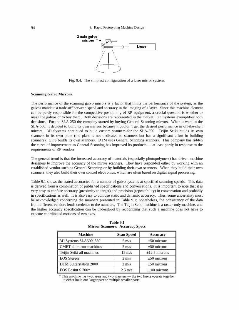
9. Rapid Prototyping Machine Design94
Fig. 9.4. The simplest configuration of a laser mirror system.
Scanning Galvo Mirrors
The performance of the scanning galvo mirrors is a factor that limits the performance of the system, as thegalvos mandate a trade-off between speed and accuracy in the imaging of a layer. Since this machine elementcan be partly responsible for the competitive positioning of RP equipment, a crucial question is whether tomake the galvos or to buy them. Both decisions are represented in the market. 3D Systems exemplifies bothdecisions. For the SLA-250 the company started by buying General Scanning mirrors. When it went to theSLA-500, it decided to build its own mirrors because it couldn’t get the desired performance in off-the-shelfmirrors. 3D Systems continued to build custom scanners for the SLA-350. Teijin Seiki builds its ownscanners in its own plant (the plant is not dedicated to scanners but has a significant effort in buildingscanners). EOS builds its own scanners. DTM uses General Scanning scanners. This company has riddenthe curve of improvement as General Scanning has improved its products — at least partly in response to therequirements of RP vendors.
The general trend is that the increased accuracy of materials (especially photopolymers) has driven machinedesigners to improve the accuracy of the mirror scanners. They have responded either by working with anestablished vendor such as General Scanning or by building their own scanners. When they build their ownscanners, they also build their own control electronics, which are often based on digital signal processing.
Table 9.1 shows the stated accuracies for a number of galvo systems at specified scanning speeds. This datais derived from a combination of published specifications and conversations. It is important to note that it isvery easy to confuse accuracy (proximity to target) and precision (repeatability) in conversation and probablyin specifications as well. It is also easy to confuse static and dynamic accuracy. Thus, some uncertainty mustbe acknowledged concerning the numbers presented in Table 9.1; nonetheless, the consistency of the datafrom different vendors lends credence to the numbers. The Teijin Seiki machine is a raster-only machine, andthe higher accuracy specification can be understood by recognizing that such a machine does not have toexecute coordinated motions of two axes.
Table 9.1Mirror Scanners: Accuracy Specs
Machine Scan Speed Accuracy
3D Systems SLA500, 350 5 m/s ±50 microns
CMET all mirror machines 5 m/s ±50 microns
Teijin Seiki all machines 15 m/s ±12.5 microns
EOS Stereos 2 m/s ±50 microns
DTM Sinterstation 2000 2 m/s ±50 microns
EOS Eosint S 700* 2.5 m/s ±100 microns
* This machine has two lasers and two scanners — the two lasers operate together to either build one larger part or multiple smaller parts.

Emanuel Sachs 95
The accuracy of the final part is dependent on both the equipment and the materials. With recentimprovements in equipment, the predominant limitation lies with the distortions introduced by the materialssystems. This is especially true of processes such as selective laser sintering where there are significantdistortions, but it is true of stereolithography as well. Hopefully, future improvements in materials systemswill demand that the equipment builders revisit their equipment designs and improve them again, as they havein the past.
Accurate calibration of laser scanner systems is key to delivering the improved systems performancesachieved today. If a scanner system has an accuracy of 50 microns over a range of 500 mm, the accuracy is 1part in 10,000. Such accuracies can only be achieved by calibration of the fully assembled machine. Severalmethods are in use, all resulting in a calibration table that is captured electronically and used by the machine.3D Systems puts down a plate with precision-drilled holes. Operators shine a laser through the holes, collectthe light, and image it onto a photodetector. The machine is then used to maximize the light transmission,and designers then know the machine settings that correspond to the hole positions. DTM burns holes in amylar film and then inspects that off-line. EOS exposes photosensitive paper and inspects that off-line.
Consistent Spot Size
Laser/galvo systems pivot the laser beam in order to scan it over the working field. In the most typicalsystem, a lens is placed before the mirrors, as shown in Fig. 9.5. The result is that the beam will be in focus atonly one distance along the optical path from this lens. As the beam is scanned over the surface of theworking area from the center position, its optical path increases; hence, the laser cannot be in focus at alllocations. The effect is more pronounced the closer the mirrors are to the imaging plane, for a given size ofthe imaging surface, due to the larger angles of deflection of the mirrors.
Fig. 9.5. The spot size changes across the vat in a galvo system (top) unless flat field optics are used (bottom).
There are several solutions to this problem. In some systems, the distortion is tolerated. Especially insystems with a large focal spot size, the increase in spot size caused by movement of the beam to the edges isconsidered to be a tolerable effect. In some equipment, the optical path length is intentionally increased byusing a focusing lens with a long focal length. Examples include the SLA 500 and the SLA 350 from 3DSystems, which have a mirror at the top of the machine and which double the optical path back to scannershoused below. The result of this approach is to effectively move the scanners further away from the imagingplane, resulting in lower angles of deflection. Thus, the change in optical path from the center of the field to

9. Rapid Prototyping Machine Design96
the edge of the field is a much smaller fraction of the optical path, and the effect on the laser spot size issimilarly reduced. This approach has the added benefit of providing a beam that is closer to perpendicularwhen it is incident on the vat surface, resulting in less distortion of the circular spot.
An alternative solution is to fundamentally modify the optical path by using a flat field lens that is placed afterthe mirror system. Such a lens system has a different focal length, depending on the position at which thelaser hits the lens. The flat field lens is thus able to maintain a constant focal spot size at the image plane.This type of optical element is more costly, however. The JTEC/WTEC panel is aware of only twocompanies that use this approach: CMET and EOS.
Starting and Stopping
In terms of drawing the scan vector, the optimum situation is one in which the vector drawn by a laser/galvosystem is uniform along its length and has the same width near the beginning, middle, and end. If the laser isturned on to full power and the mirrors are simultaneously accelerated, the effect will tend to be like thatshown in Fig. 9.6, where the vector is wider near the ends where the laser spot is either accelerating ordecelerating and the power density of the laser is higher.
Fig. 9.6. Turning the laser full on immediately results in a scan vector that is wider at thebeginning and end of the vector.
A number of solutions to this problem are currently in use. Teijin Seiki uses an acousto-optic modulator(AOM), which is placed between the laser and the galvo system. With this device, it is possible to do pulse-width modulation of the laser power that goes through the galvos; by varying the duty cycle of the laser powerreaching the vat, engineers are able to effectively reduce the laser power during acceleration and decelerationof the beam, resulting in a constant power density at the vat. D-MEC uses a “high-speed light modulator”(probably this is an AOM). In its equipment, DTM does pulse-width modulation of an RF-excited laser.
3D Systems uses an AOM, but only for turning the laser on and off at the beginning and end of the vector, notfor pulse-width modulation. As noted earlier, 3D Systems builds its own scanners and control electronics,and these high-speed systems allow the company to minimize the impact of the acceleration and decelerationphases of its vectors.
GROUP 2: LASER
Returning to the classification scheme, machines that use lasers constitute a broad class of systems that cutacross categories of the matrix presented here. (The laser/galvo systems make up a subgroup of thesesystems.) This class is shown in Fig. 9.7.

Emanuel Sachs 97
Imag
ing
me
chan
ism
2 axes optical1 axis mechanical
3+ axes mechanical
Imaging strategy
Vector outline Raster only
Selective Laser Sintering/DTMEosint/EOS
Laser Photolitho/Teijin-SeikiLaser Photolitho/CMETLaser Photolitho/DMEC
Laser Photolitho/Meiko
Laser Photolitho/ Fockele & Schwarze
LOM/Helisys
Laser Generated RP/IPTLENS/Sandia
Laser Photolitho/CMET
Laser Photolitho/EOS
Fig. 9.7. Systems with lasers.
Spot Size
Table 9.2 shows the spot size achieved in various laser-based RP machines, including both mirror and gantrytypes of machines. As can be seen, most systems have spot sizes of 150-200 or 250 microns. There are a fewexceptions, notably the DTM machine that has a significantly larger spot size (400 µm), and two machineswith significantly smaller spot sizes: a 3D Systems Beta machine (80 µm) and the Nagoya photomoldingmachine (5 µm).
Table 9.2Spot Size
Machine Spot size (diameter)
3D Systems SLA 250, 350, 500 250 microns
3D Systems Beta 80 microns
DMEC (500 x 500 mm)* 150 microns
DMEC (800 x 1000 mm) 300 microns
CMET mirror 200 microns
CMET gantry** 130 microns
Teijin Seiki 150 microns
EOS Stereos 200 microns
DTM 400 microns
Sintering/Bavarian Laser Center Concentric dual beam
Helisys/LOM 250 microns
Photomolding/Nagoya 5 microns
* older, smaller machine has variable spot size ** variable spot size, 130-1500 microns

9. Rapid Prototyping Machine Design98
An important source of perspective on the data of Table 9.2 is to recognize that there is a fundamental lowerlimit to the spot size that can be achieved from a collimated light source. This is given by the expression
Minimum spot size=λ ⋅ f
d
where λ is the wavelength of the light, f is the focal length of the focusing lens, and d is the diameter of thecollimated beam that enters the lens. Thus, the smallest focal spot will be achieved with a large-diameterbeam entering a lens with a short focal length.
As noted above, in a laser/galvo system, there is an advantage to moving the mirrors (and therefore focusinglens) far from the imaging plane in order to achieve better control over the size and shape of the focal spot.However, as can be seen from the equation above, a longer focal length acts to increase the minimum spotsize that can be achieved. In order to compensate for this effect, a beam expander may be placed in theoptical path before the focusing lens. This solution is employed in many laser/galvo systems, as shown inFig. 9.8.
Fig. 9.8. A laser/mirror system with a beam expander in the optical path.
This strategy, too, has its limits. As the beam diameter is increased, the mirrors in the galvo system must beincreased in size and mass, potentially resulting in a loss of performance. However, most laser/galvo systemsdo use a beam expander in order to bring the focal spot down into the typical range of 150-200 microns.
The larger, 400-micron spot size of the DTM machine can be understood by noting that no beam expander isused in this machine. The laser sintering machine at the Bavarian Laser Center uses a concentric dual beam.The larger beam preheats and anneals the powder, while the inner beam performs the sintering.
A standout on the smaller end of the scale is the small, 80 µm spot size of the 3D Systems Beta machine,which is a retrofitted SL250 machine in beta testing. In this machine, several modes of the HeCd laser arefiltered out, resulting in a beam that can be focused to a smaller spot size. In the process, most of the betaenergy is lost.
Achieving a small and well-controlled spot size is less difficult in a gantry machine. For example, in theLOM (laminated object manufacturing) machine, the focusing lens is carried on the gantry and is much closerto the imaging plane (approximately 10-15 cm distance) than it is in a galvo mirror machine. For this reason,no beam expander is needed before the focusing lens. Further, there is no change in angle of incidence of thebeam, and hence no distortion of the shape of the beam. The photomolding machine at Nagoya is intendedfor MEMS (microelectromechanical) application and so uses a very small spot indeed. The gantryconstruction of this machine helps in achieving this small spot size.

Emanuel Sachs 99
A possible strategy with a laser machine is to change the size of the spot, depending on the geometry beingimaged. For example, a small spot size might be used to scan the perimeter of a part in a vector motion withfine detail, followed by use of a large spot to achieve a raster fill of the geometry. An older DMEC machineand a CMET machine have such capability.
Recoating in Laser Photolithography
Many machines in the laser class are photolithography machines (both vector and gantry), and recoating is animportant aspect of the design and performance of these machines. The technique used can influence (1) therange of resin properties that are allowed in a machine, (2) the flatness of the resin surface produced, and (3)the speed of recoating. Recoating has been an important source of differentiation among competing laserphotolithography products. There are essentially four approaches used in systems that build parts in a vat ofpolymer: deep dip, inverted “U,” viscous retention, and positive displacement (Fig. 9.9).
The “deep dip” approach is perhaps the most widely used recoating method. As shown in Fig. 9.9a, the partis lowered into the vat by a distance greater than the intended layer thickness to promote the flow of a viscousresin over the surface of the part. The part is then raised to the height that it should be when the next layer isimaged, and a mound of photopolymer is created above the free surface of the resin in the vat. A blade thenmoves across and wipes the excess resin off to the side, leaving the desired layer thickness. This method is asubstantial improvement over the previous method where gravity was relied on to level the surface (this wasslow); however, it can be sensitive to part geometries such as that shown in Fig. 9.9a where there is a “trappedvolume” of resin. As the blade wipes across, the resin in this volume may be shifted, with the result that thelayer thickness after equilibration is not quite as desired. This method is used by 3D Systems and DMEC(DMEC’s blade flips up at the end of a pass).
Deep dip
Inverted “U” (Capillary, vacuum, electrostatic)
Viscous retention
Positive displacement pump
(a)
(b)
(c)
(d)
Fig. 9.9. Recoating methods in laser photolithography.
Fig. 9.9b shows the “inverted ‘U’” approach, where a coating device is filled with resin above the free surfaceof the vat, and this resin is then dispensed as the coater traverses the vat. Filling of the inverted “U” can beby capillarity, electrostatics, or vacuum. The trailing edge of the recoater acts as a doctor blade. This methodis relatively immune to the problem of trapped volumes and can be faster than the deep dip, since no stage isstrongly dependent on gravity-induced flow. CMET uses capillary filling of the recoater (although there mayhave been a communication problem on this issue). Fockele and Schwarze uses the electrostatic method,although it apparently does not work equally well with all polymers. 3D Systems uses the vacuum method.

9. Rapid Prototyping Machine Design100
Fig. 9.9c shows the method of “viscous retention.” A brush or mesh (depending on the resin) is supportedbetween two doctor blades. While the layer is being imaged, this device is submerged in the vat. When it istime to recoat, it comes up and over the surface of the vat, and the material drains out by gravity as a ratedetermined by the viscosity of the resin. The final surface is created by the trailing doctor blade. Teijin Seikipractices this method.
Fig. 9.9d shows a positive displacement pump used to bring material up for the new layer. This method isused by EOS.
GROUP 3: ALL AXES MECHANICAL
A large number of RP machines fall into the classification, all axes mechanical (Fig. 9.10).
Ima
ging
me
chan
ism
2 axes optical1 axis mechanical
3+ axes mechanical
Imaging strategy
Vector outline Raster only
Ballistic Particle/Perception
Fused Dep Model/Stratasys
Laser Photolitho/Meiko
LOM/HelisysSAHP/Kira
Multi-phase Jet /IFAM and IPA
Laser Generated RP/IPTLENS/Sandia
Laser Photolitho/CMET
Shape Dep Model/CMU,Stanford
Fig. 9.10. Machines with all-mechanical imaging systems.
Mechanical Actuation
There is no predominant technology in use to effect the mechanical motions in RP machines. A wide varietyof the technologies in general use for positioning in industry are in evidence in RP machines, with a focus onelectrical actuation (as opposed to hydraulic or pneumatic actuation). Often a machine uses differentapproaches for its different axes. For example, the recoater in a laser photolithography machine might becable-driven from a capstan, while the vertical axis is driven by a ball screw. In most cases, control iseffected using either a stepper motor or a servo motor with a rotary encoder on the motor, but some cases alsoexist of linear encoding on a slide. In general, research organizations tend to buy integrated motionassemblies for their RP machines, but commercial organizations often buy the machine elements and docustom integration. For some vendors, this approach is dictated by cost; for others it is dictated byperformance considerations.

Emanuel Sachs 101
Material Delivery
An important subset of the all-axes-mechanical RP machines have the feature in common that they delivermaterial. The device used to deliver material is generally a critical part of these technologies and often(perhaps always) embodies proprietary developments by the machine builder.
• In Fused Deposition Modeling (FDM) as practiced by Stratasys, the extrusion head must deliver thematerial at a well-defined temperature in order to promote bonding while maintaining the shape of theextrudate. Further, controlling the width of the “road” is critical to achieving dimensional control of theprocess.
• In Ballistic Particle Manufacturing (BPM) and in 3D Printing, the ink-jet printheads that are used todeliver material determine the geometry of the component. BPM adds the further demand of having toaccurately control the temperature of the droplets of material so that they fuse properly to the part. In 3DPrinting, taking full advantage of the capability of the process to print different materials in differentlocations requires the development of a printhead that can accommodate a range of binder materials.
• In the LENS process, in Laser Generated RP, and in other similar techniques, the technology used todeliver powder to the molten pool maintained by the laser is critical to achieving the desired materialproperties, and probably, to achieving z-axis dimensional control.
• In Shaped Deposition Manufacturing (SDM), the deposition nozzle is critical to achieving the desiredmaterial properties.
Sheet Machines
The class of machines that construct from sheet material is a subset of the all-axes-mechanical type. While itis possible to have a sheet machine that images optically, the nature and speed of the devices used to cut theoutline of the sheet suggests that an all-mechanical approach is probably more suitable. Most of the cuttingdevices in use or under consideration are either fairly massive or have contact force interaction with the sheet.The exception is laser cutting, but in this case, cutting speeds are slow compared to imaging in astereolithography vat, and mechanical actuation has some advantages in this regime of operation.
Table 9.3 summarizes the interesting contrast that may be drawn between two different approaches tobuilding with paper as the feedstock, as practiced in the Helisys LOM process and in Kira’s SAHP (selectiveadhesive and hot press) process, which represents a highlight in new machine configurations in Japan.
Table 9.3LOM/Helisys vs. SAHP/Kira
LOM SAHP
Work area 500 x 760 mm 280 x 400 mm
Paper supply Paper roll Plain paper sheet
Lamination method Hot roller Hot press
Adhesive application Preapplied to roll Selective laser printer
Paper cutting CO2 laser Knife plotter
Work environment Lab or shop floor Office
LOM can make quite large parts from a roll of paper as feedstock. In LOM the adhesive is preapplied to theroll and a new layer is added to the stack by hot roll lamination. A laser is used to cut the sheet. The use ofthe laser restricts this process to a lab or shop floor. The strength of the SAHP machine is that it assemblescommercially available imaging tools in an office environment. The machine works from cut-sheet paper and

9. Rapid Prototyping Machine Design102
selectively applies the adhesive with a laser printer. After hot press lamination, the sheet is cut with a knifeplotter using a carbide knife. The chief weakness of the SAHP machine is that it is limited in size by the needto purchase a commercial laser printer, and Kira designers state that they have no intention of going beyondthe size of their current machine. Minor limitations include the need to periodically replace the knife, and thefact that the paper used is sensitive to moisture.
Both LOM and SAHP make a cut that is nominally perpendicular to the sheet material. Another point ofdeparture is to cut the sheet with beveled edges so as to reduce the stair-stepping effect. Work at CaseWestern Reserve in the United States is exploring 4-axis cutting with a laser. Most of this work has beendone with tape-cast ceramic sheet (sheet made of particles held together by a polymer binder). In this case,the sheet is cut and then stacked; it would be difficult to imagine how bevel-cutting could be accomplished bystacking and then cutting, since the cut would have to terminate immediately after the first layer, and the longcut involved in a bevel cut would be difficult to control with the necessary accuracy. Work that started atMIT and continues at Rensselaer Polytechnic Institute is exploring alternate methods of 4-axis cutting ofmetal sheet, including laser, water jet, and machining techniques.
Professor Nakagawa at the University of Tokyo intends to build a metal lamination machine for large tooling.On the question of 2-axis versus 4-axis cutting he acknowledged the issues associated with cutting sheet withvery small bevel angles; however, he did not indicate which approach he is pursuing.
GROUP 4: THERMAL PROCESSING
The final broad class of machines has in common the property that thermal processing plays a strong roleduring the RP process. This thermal processing role is crucial because of (1) the generation of thermalstresses in the part as it is being formed, and (2) the attainment of the desired physical properties of the part.Designing the equipment used to effect the thermal control is often one of the most challenging aspects ofthese processes.
In FDM, it has already been noted that control of the extrudate temperature is critical. In addition, however,the control of the temperature in the atmosphere around the part has been found to be important in controllingpart distortion. Similarly, in laser sintering, the control of the environment and the powder is crucial tocontrol of residual stress and distortion. This control is particularly challenging because the powder bed mustbe held at an elevated temperature so as to further reduce the generation of stress. In the processes thatlaminate sheet such as hot roll with LOM and hot press with SAHP, the design of these laminators so as tominimize the introduction of stress has been a major focus of machine design efforts. In SDM, minimizingthe stress introduced when a new layer of material is applied is an important consideration. In the LENSprocess and other similar processes, no studies of residual stress have yet been conducted; however, it ispossible that such stresses will be strongly dependent on processing parameters.
GENERAL OBSERVATIONS ON MACHINE DESIGN
• There is pioneering work in machine design taking place in all three regions surveyed, the United States,Europe, and Japan.
• At present, the regional best machine design is at rough parity in the three regions.
• Japan is working toward developing RP machines that can compete with CNC machines in performance(especially accuracy) and in price. At present, the focus of this work is on laser photolithography.
• There is a strategic issue of access to suppliers of lasers, scanners, and other critical components.

103
CHAPTER 10
METAL CASTING APPLICATIONS
Clinton L. Atwood
OVERVIEW OF THE INVESTMENT CASTING PROCESS
Investment casting, often called lost wax casting, is regarded as a precision casting process to fabricate near-net-shaped metal parts from almost any alloy. Although its history lies to a great extent in the production ofart, the most common use of investment casting in more recent history has been the production of componentsrequiring complex, often thin-wall castings. While a complete description of the process is beyond the scopeof the discussion here, the sequential steps of the investment casting process will be briefly described, withemphasis on casting from rapid prototyping patterns.
The investment casting process begins with fabrication of a sacrificial pattern with the same basic geometricalshape as the finished cast part (Fig. 10.1a). Patterns are normally made of investment casting wax that isinjected into a metal wax injection die. Fabricating the injection die often costs tens of thousands of dollarsand can require several months of lead time. Once a wax pattern is produced, it is assembled with other waxcomponents to form a metal delivery system (Fig. 10.1b), called the gate and runner system. The entire waxassembly is then dipped in a ceramic slurry, covered with a sand stucco (Fig. 10.1c), and allowed to dry. Thedipping and stuccoing process is repeated until a shell of ~6-8 mm (1/4-3/8 in) is applied.
Initial pattern, traditionally wax, is produced slightly larger than final metal part.
Metal delivery system is thenassembled on the pattern.The gating system is usuallymade from standard waxshapes.
Wax assembly is then successively dipped in ceramic slurry and stuccoed with sand to produce shell.
a
b
c
Fig. 10.1. Investment casting process description.

10. Metal Casting Applications104
Once the ceramic has dried, the entire assembly is placed in a steam autoclave to remove most of the wax(Fig. 10.2a). After autoclaving, the remaining amount of wax that soaked into the ceramic shell is burned outin a furnace (Fig. 10.2b). At this point, all of the residual pattern and gating material is removed, and theceramic mold remains. The mold is then preheated to a specific temperature and filled with molten metal,creating the metal casting (Fig. 10.3a). Once the casting has cooled sufficiently, the mold shell is chippedaway from the casting. Next, the gates and runners are cut from the casting, and final postprocessing(sandblasting, machining) is done to finish the casting (Fig. 10.3b). Fig. 10.4 shows the CAD solid model,the shell, and the pattern produced in the QuickCast process.
High PressureSteam
Recovered Wax
The mold is then placed in a steamautoclave for de-waxing.
a
Residual wax is then firedfrom the shell.
b
Fig. 10.2. Investment casting process description (cont’d.)
Mold is preheated, andmolten metal is poured intothe mold cavity.
a After cooling, the ceramicshell is chipped or blastedoff, and the metal partattached to gating systemremains.
b
Fig. 10.3. Investment casting process description (cont’d.)

Clinton L. Atwood 105
Fig. 10.4. CAD solid model (top), ceramic shell with QuickCast pattern (left), QuickCast pattern (right).
The major impact rapid prototyping processes have had on investment casting is their ability to make high-quality patterns (Fig. 10.5) without the cost and lead times associated with fabricating injection mold dies. Inaddition, a pattern can be fabricated directly from a design engineer’s computer-aided design (CAD) solidmodel. Now it is possible to fabricate a complex pattern in a matter of hours and provide a casting in a matterof days. Investment casting is usually required for fabricating complex shapes where other manufacturingprocesses are too costly and time-consuming. Another advantage of rapid prototyping casting is the low costof producing castings in small lot sizes.
Fig. 10.5. CAD solid model (top), SLS polycarbonate pattern (left), A356 aluminum casting (right).

10. Metal Casting Applications106
METAL CASTING APPLICATIONS IN THE UNITED STATES
Investment Casting
The United States is clearly the world leader in the use of rapid prototyping processes for metal castingapplications. Metal casting from RP patterns is widely used by government and industry, cross-cuttingnumerous markets, including those for automotive, aerospace, medical, and consumer products. The use ofRP patterns for investment casting continues to increase as processes evolve and pattern quality improves.There is already a significant number of U.S. companies applying RP to metal casting, as Table 10.1 shows.3D Systems’ stereolithography (SL) process is often used to fabricate patterns for investment casting. TheQuickCast build style, coupled with CibaTool and other epoxy resins, is now used by many U.S. companiesto fabricate complex patterns quickly for investment casting of metal parts. DTM Corporation’s SelectiveLaser Sintering (SLS) process is used to fabricate investment casting patterns from several materials,including investment casting wax, polycarbonate, and a recently released proprietary material calledTrueForm. The use of the SLS process to fabricate investment casting patterns continues to increase asmaterial performance and accuracy improve. To date, however, far fewer SLS machines are in use than SLmachines. Other RP processes used in the United States to fabricate investment casting patterns includeStratasys’ Fused Deposition Modeling (FDM); Helisys’ Laminated Object Manufacturing (LOM); Cubital’sSolid Ground Curing (SGC); Sanders Prototype’s Model-maker; and BPM (Ballistic Particle Manufacturing)Technology’s process. The Soligen Direct Shell Production Casting (DSPC) process yields investment castparts by directly fabricating an investment casting mold without the use of a pattern.
Table 10.1U.S. Rapid Prototyping Manufacturers’ Applications for Metal Casting
Rapid Prototyping Process Metal Casting Application
3D Systems Stereolithography QuickCast patterns for investment castingEpoxy patterns for precision sand casting and soft tooling
DTM Selective Laser Sintering Investment casting wax, polycarbonate, and TrueFormpatterns for investment castingTrueForm, composite nylon, polycarbonate for precisionsand casting and soft toolingRapidTool for hard tooling investment casting patterns
Stratasys Fused Deposition Modeling Wax patterns for investment casting
Helisys Laminated Object Manufacturing Laminated paper master patterns for sand casting, limiteduse for investment casting
Soligen Direct Shell Production Casting Ceramic investment casting mold fabricated directly fromCAD solid model
Cubital Solid Ground Curing Patterns for flask mold casting; process for fabricatingwax investment casting patterns under development
BPM Ballistic Particle Manufacturing Wax patterns for investment casting
Sanders Model-Maker 3D Plotting Wax patterns for investment casting
METAL CASTING APPLICATIONS IN EUROPE (GERMANY AND FRANCE)
In Europe the use of RP for investment casting is limited but increasing. As the use of CAD solid modelingincreases, application of rapid prototyping for manufacturing metal investment castings will also increase.Table 10.2 summarizes some German-manufactured rapid prototyping systems.

Clinton L. Atwood 107
Table 10.2German Rapid Prototyping Manufacturers’ Applications For Metal Casting
Rapid Prototyping Process Metal Casting Application
Electro Optical Systems (EOS)
Stereos Laser Stereolithography
Investment casting patterns fabricated using Skin & Coresoftware and AlliedSignal Exactomer resin
EOSINT P Laser Sintering Investment casting patterns fabricated using polystyrenematerial developed jointly with the University of Stuttgart IKP
EOSINT S Laser Sintering Sand casting molds and cores fabricated directly from CADsolid model using polymer-coated green sand
Dassault Aviation (France) is a frequent user of RP patterns for investment casting. In the same manner asmany U.S. companies, Dassault designs and manufactures complex metal castings using 3D Systems’QuickCast build style to fabricate patterns. Dassault engineers have worked with several foundries to developprocess parameters for successfully casting RP patterns. Dassault has certified RP castings for use in testingprototype flight hardware. In addition, some German companies use the expertise of Dassault to get metalcastings from RP patterns.
The European automotive industry has also had success using RP castings. Typically, a company sends aCAD solid model of the design to the United States for pattern fabrication, a U.S. foundry does the casting,and the part is delivered back to the company. One such successful case study is documented in the recentlypublished book Stereolithography and other RP&M Technologies (Jacobs 1996). Mercedes-Benz Divisionof Daimler-Benz designed a new four-cylinder engine block using CATIA solid modeling software. Thesolid model design of the full-size engine block was sent to 3D Systems Technical Center in Darmstadt,Germany, for pattern fabrication. The completed investment casting pattern was then sent to Solidiform, Inc.,in Dallas, Texas, for investment casting. The completed aluminum casting was then sent back to Mercedes-Benz, resulting in a significant savings in time and cost.
Schneider Prototyping, the largest service bureau in Germany, has developed a proprietary process for castingmetal parts from the Cubital SGC process. Metal castings account for 15-20% of Schneider’s work. Cubitalis developing a process for fabricating wax patterns by capturing a wax shape within a thin polymer coating.
The Fraunhofer Institute for Applied Materials Research (IFAM) currently uses the Stratasys FDM process tofabricate wax patterns for investment casting. It is also involved in a demonstration project for investmentcasting of custom medical implants in a joint effort with a medical clinic, an implant manufacturer, and aninvestment casting foundry.
Electro Optical Systems (EOS), a manufacturer of rapid prototyping systems, is developing processes andmaterials focused on metal casting applications.
Research and Development
Cubital is developing a process for fabricating wax patterns for investment casting by capturing the wax shapewithin a thin polymer coating. The polymer coating is subsequently removed, leaving the wax pattern.
Conclusion
The enabling technology for use of rapid prototyping processes is CAD solid modeling. The CAD solidmodel captures the geometry, which can be easily processed in any RP machine. The use of CAD solidmodeling in Europe is not widespread; however, its use and application are increasing. As the use of solidmodeling and rapid prototyping increases, the use of investment RP patterns is increasing as well. European

10. Metal Casting Applications108
RP manufacturers recognize the potential for metal casting applications and are developing new processesand materials for use in metal casting. In addition, German foundries are learning to cast RP patterns. Theyhave had more success casting polystyrene patterns than stereolithography QuickCast patterns.
METAL CASTING APPLICATIONS IN JAPAN
As in Germany, the use of CAD solid modeling in Japan is limited. Again, as the enabling technology forrapid prototyping machines, a CAD solid model must be created before a part can be fabricated. The use oftwo-dimensional CAD is very common in Japan. Often a 2D CAD file is translated to a 3D CAD solidmodel, then fabricated on an RP machine, but the extra step of creating the solid model increases the cost ofthe RP part. In Japan, rapid prototyping competes with machining for producing prototype parts. In manycases, even complex geometries can be machined as fast as parts can be fabricated using RP. There arehundreds of small machine shops in Japan, and the competition for work makes machining an attractivealternative to RP. Another reason RP competes with machining is the lower accuracy and surface roughnesslimitations of RP parts. As the use of CAD solid modeling increases, the use and application of RP isexpected to increase. This was evident by the use and application of RP in some of the small progressivecompanies that the JTEC/WTEC panel visited.
Table 10.3 summarizes some of the rapid prototyping systems in use in Japan.
Table 10.3Japanese Rapid Prototyping Manufacturers’ Applications for Metal Casting
Rapid Prototyping Process Metal Casting Application
CMET Solid Object Ultra-violet laser Plotter(SOUP)
Epoxy investment casting patterns fabricated usingproprietary software that generates triangle or rectanglehatches to build quasi-hollow patterns. This process isalso used to fabricate solid patterns for sand casting.
Design Model Engineering Center (DMEC) SonySolid Creator
Investment casting patterns fabricated in Sony processusing JSR polyurethane acrylic resin
Teijin Seiki Soliform Solid Forming System Teijin Seiki is working with DuPont to develop a newresin (SOMOS 4100) for use in fabricating patterns forinvestment casting.
Kira Solid Center/Selective Adhesive and HotPress Process (SAHP)
Laminated paper patterns for sand casting
Meiko Plaster casting patterns for Japanese jewelry industryusing a relatively low-accuracy photo-resin system.Process is used to fill void from lack of skilledcraftsmen to make patterns.
Denken (There was no mention of the use of Denken’s processfor metal casting applications.)
INCS, Inc., is the largest service bureau in Japan. It uses 3D Systems stereolithography machines to buildQuickCast patterns for investment casting. This accounts for approximately 15% of its work. INCSengineering staff and technicians are very knowledgeable about RP, and the parts that they displayed to thepanel are of excellent quality. The company has worked with investment casting foundries to cast theCibaTool 5180 epoxy QuickCast patterns. According to INCS’ staff, there are five foundries in Japancapable of casting RP patterns. They also stated that investment casting in Japan is a $600 million industry.

Clinton L. Atwood 109
Nakamura Pattern Company is a small pattern making company that has 20-25 employees. As a traditionalsand casting pattern builder, most of its employees are skilled pattern makers. However, this group of skilledpattern makers is advancing in age (the average age is 50 years), and the company is having trouble attractingreplacement workers to be trained as skilled pattern makers. As a result, Nakamura Pattern Company ownersdecided to investigate RP as a limited alternative to traditional hands-on pattern making. They visited theUnited States and attended the SME/RPA Rapid Prototyping and Manufacturing Conference and Expositionin Dearborn, then toured several U.S. companies, including Helisys. After thorough investigation of severalrapid prototyping processes, Nakamura chose to purchase a Helisys LOM machine.
Nakamura has integrated the LOM machine into its manufacturing base, using it for fabricating complexpatterns for sand casting. It is run on a 24-hour basis. Right next to it is a CNC (computer numerical control)wood-milling machine. Depending on accuracy requirements, the company chooses between CNC machiningand the LOM machine for pattern fabrication. CNC is used for greater precision, but the LOM machine iseasier to use. Company representatives estimate that using the LOM machine has increased business by 50%(Sites, 1996, 92-94).
One of Nakamura’s advantages in using rapid prototyping to fabricate sand patterns is that it is actively usingCAD solid modeling. The company uses several types of CAD solid modeling software, and its staff is welltrained. This company has been very progressive in its use of new technology (RP and CNC); at the time ofthe JTEC visit, its management intended to look into purchasing another LOM machine within the next yearor so.
Toyota Motor Corporation is in the process of evaluating rapid prototyping for metal casting. It has donesome benchmarking with selective laser sintering and stereolithography as well as LOM, and it is just nowlooking at metal casting applications. Preliminary results of Toyota’s benchmarking indicate that there arelimitations to each of the RP processes it is investigating. It, too, is comparing CNC machining to rapidprototyping.
Hino Motors, Ltd. is a user of 3D Systems stereolithography apparatus (SLA-500). It is currently in theprocess of upgrading its machine to build investment casting patterns using QuickCast software and CibaTool5180 epoxy resin. Its engineers also see potential in the use of solid stereolithography patterns for sandcasting applications. Evaluation of this application is underway.
Tokuda Industries uses the Kira Solid Modeler to make paper patterns for sand casting. Tokudarepresentatives stated to JTEC/WTEC panelists that there were some drawbacks to this process, in that itrequires attended operation, and the accuracy and surface quality are less than desirable. They also stated thatalthough the Kira process is less expensive, it is slower than CNC milling.
Research and Development
As previously stated, research and development for metal casting applications in Japan is primarily focusedon materials and software development for pattern fabrication. There has been some R&D done by ProfessorNakagawa in the area of casting and computer simulation. This work is documented in a paper “Applicationsof Laser Stereolithography to Casting and Computer Simulation” (Nakagawa et al. n.d.).
Conclusion
In Japan, CAD solid modeling is not widely used. In many cases, part designs have to be translated into solidmodels before fabrication by a rapid prototyping machine. This increases the cost of RP parts. Rapidprototyping is compared to (and competes against) CNC machining with respect to cost, scheduling, andquality. Insufficient accuracy and surface quality of parts fabricated using RP processes are limiting their usein Japan. Small progressive companies like Nakamura Pattern Company and INCS are aggressively andsuccessfully using rapid prototyping for metal casting applications.

10. Metal Casting Applications110
REFERENCES
Jacobs, P. F. 1996. Stereolithography and other RP&M technologies. Dearborn, Michigan: Society ofManufacturing Engineers (in cooperation with the Rapid Prototyping Association of SME and theAmerican Society of Mechanical Engineers, New York).
Maguire, M. C., M. D. Baldwin, C. L. Atwood, B. T. Pardo. 1995. Rapid prototyping technologies and theirapplication to metalcasting. American Metalcasting Consortium.
Nakagawa, T., et al. n.d. Applications of stereolithography to casting and computer simulation. Tokyo,Japan: University of Tokyo Institute of Industrial Science, and Saitama, Japan: Institute of Physical andChemical Research.
Sites. 1996. This reference designates the companion volume to this JTEC/WTEC report: Prinz, F. B.,ed. JTEC/WTEC panel report on rapid prototyping in Europe and Japan. Vol. II. Site reports.Baltimore, MD: Loyola College. NTIS Report #PB96-199583.1

111
CHAPTER 11
TOOLING APPLICATIONS
Richard F. Aubin
INTRODUCTION
In the United States today, there is a greater variety of rapid prototyping tooling applications than in mostother countries. U.S. engineers, scientists, technicians, and business people seem to brainstorm this relativelynew technology in aggressive ways to try to find an appropriate fit for various applications. In so doing, theyhave found novel and creative applications of rapid prototyping (RP) to the manufacture of parts and tools.
The JTEC/WTEC panel visited a number of European and Japanese academic and commercial organizationsperforming excellent and interesting work in the application of RP to tooling. Their programs cover a varietyof applications of RP technologies and the manufacture of various tools. This chapter reviews theapplications that the JTEC/WTEC panel observed in Europe and Japan. While the panel found many of itshosts to be open and casual, it should be acknowledged that organizations’ natural propensity to protect theirintellectual property is especially visible in rapid prototyping application development. Although the rapidprototyping equipment is in the public domain, how this technology is applied to attain competitive advantageremains sensitive. Accordingly, the following information is a reflection of what was considerednonproprietary by the panel’s hosts. It is to be expected that there are a lot more proprietary toolingapplication efforts underway than were shared with the panel.
There are a number of special considerations when applying rapid prototyping to tooling. In some cases,parts or tools must be plated with a thin coat of metal to facilitate their use in a harsh environment. In othercases, it is necessary to fabricate holding fixtures for parts to be inspected in coordinate measuring machines(CMM), or to hold parts that will be machined via electronic discharge machining (EDM). Even though it ispossible to render a fixture that can hold a complex delicate part for some touch-probing inspection directlyfrom a computer model, or to EDM a part with little to no tool pressure on the part, there is a certain amountof cultural change that is necessary before manufacturers or their clients are ready to take this step.Manufacturers need to be convinced that if there is not a lot of pressure on the tool, and it is just going to beholding something statically positioned, a plastic tooling fixture will suffice in place of a metal fixture. It isin willingness to embrace this kind of cultural change that the panel feels the United States is, in general,further ahead than the European countries and Japan. However, there is a considerable amount of innovativeRP tooling work underway in France, Germany, and Japan.

11. Tooling Applications112
RAPID PROTOTYPING TOOLING APPLICATIONS IN EUROPE
The JTEC/WTEC panel visited 11 sites in Europe that have RP tooling applications (all are in Germany,except as noted):1
1. Fraunhofer Institute for Manufacturing Engineering and Automation (IPA), Stuttgart2. Fraunhofer Institute for Chemical Technology (ICT), Pfinztal3. Fraunhofer Institute of Applied Materials Research (IFAM), Bremen4. Fraunhofer Institute for Production Technology (IPT), Aachen5. Institute for Polymer Testing and Polymer Science (IKP), University of Stuttgart6. The Bavarian Laser Center (BLZ), Erlangen7. Catholic University of Leuven and Materialise Co. (both of Belgium)8. EOS (Electro Optical Systems), Munich9. Cubital (and Schneider Prototyping), Bad Kreuznach10. Laser 3D and Dassault Aviation, Villers-Les-Nancy (France)11. Daimler-Benz, Sindelfingen
Seven Fraunhofer institutes, with financial support from the German government, are cooperating in a rapidprototyping network to speed up the development, advancement, and dissemination of rapid prototypingtechnologies to improve the competitiveness of the German manufacturing industry. (The main emphasis ofthis network is metallic prototypes; see Chapter 6.) The seven Fraunhofer institutes are the four listed above,and the following three (not visited by the panel):
1. Fraunhofer Institute for Graphic Data (IGD), Darmstadt2. Fraunhofer Institute for Laser Technology (ILT), Aachen3. Fraunhofer Institute for Production and Construction Technology (IPK), Berlin
What the JTEC/WTEC panel learned in its interviews at the Fraunhofer Institutes is that they are all very wellprepared. The Fraunhofer Institutes have a broad knowledge base, a lot of experience, and a lot of shop-smart expertise. The developments underway at their facilities should not be underestimated.
Although there are various cooperative arrangements between them, each of the Fraunhofer Institutes focuseson a different issue: one takes software, another material development, still another focuses on applications,etc. The JTEC/WTEC panel found that by using this approach, the institutes are building a comprehensiveinfrastructure for rapid prototyping. The Fraunhofer labs are pristine, with brand new equipment. However,they had few parts at the time of the panel’s visit, because they are just developing their infrastructure. Thepanel expects that once the laboratories are fully in place, they will be a strong force. Their integratedinformation model for rapid prototyping as shown in Fig. 11.1 is very impressive and worthy of note. Thereis nothing comparable in the United States.
Fraunhofer Institute for Manufacturing Engineering and Automation (IPA)
There is continued work at IPA on reverse engineering, or the use of physical models as computer input data.Some of this work was initiated during the Intelligent Manufacturing Systems IMS test case program of 1993.Here, laser scanning, optical and tactile measurement systems, X-ray computer tomography, and 3Dultrasonic sensors are applied for the shape digitizing of models to create a point cloud, which is then fedback into a CAD system to generate a CAD model for further evaluation. In an interesting development, IPAresearchers are now working on integrating that process with software tools for surface segmentation, pointcloud management, and curve fitting to virtual prototyping and physical prototyping. See Figs. 11.2a and11.2b.
1 See also the individual site reports in Sites 1996.

Richard F. Aubin 113
Fig. 11.1. The Fraunhofer integrated information model for rapid prototyping.
Fig. 11.2a. Scanned point cloud model. Fig. 11.2b. Solid model from scanned data.
Researchers at IPA are also investigating coating technologies by applying metallic coating tostereolithography plastic parts for applications like EMI shielding and tooling. The coating processes includePVD, electroplating, and electrolysis plating. One benefit of coatings is that when an otherwise fragilecomponent is coated with a metal, it acquires new characteristics and can be capable of withstanding harsherenvironments for downstream applications. This allows the part, component, or tool to be useful in newapplications. Another benefit of coatings is that they can fill in the staircasing of the part, providing asmoother surface.
Another useful development at IPA is in the area of information and organization. IPA uses a qualityfunction deployment (QFD) approach (Fig. 11.3) for selecting the most appropriate rapid prototypingtechnology.

11. Tooling Applications114
Fig. 11.3. Quality function deployment (QFD) approach to selecting most appropriate RP technology.
Although this work is not being done in the area of tooling at the present time, it certainly can be, withpotentially very beneficial results. If the tooling industry can have an intelligent selector based on a tool’sfeatures and other requirements, designers will be able to very quickly determine what best fabricationapproach to use for tooling or for casting, as well as what materials to use, and so forth. This could be one ofthe measures that could tie into a STEP application protocol, as discussed in Chapter 8. There are numerouspotential applications and implications for IPA’s QFD approach.
Fraunhofer Institute for Chemical Technology (ICT)
At ICT, the JTEC/WTEC panel found an example of rapid prototyping being used to make the cavity andcore of a plastic injection mold. ICT researchers are making the mold inserts to go into a steel mold set. Inthis case, the mold is for an electrical receptacle. Using the 3D Systems stereolithography SLR-5180 epoxyresin, they were able to process some 200 parts in a variety of materials, including the following:

Richard F. Aubin 115
• polystyrene at 240ºC, 1,000 Bar, 40-second cycle
• ASA at 210ºC, 900 Bar, 40-second cycle
Their next step is to try to find ways to integrate the use of additional core pulls or slides so that they canmold more complex geometric features. Fig. 11.4 shows the mold cavity.
Fig. 11.4. Stereolithography mold cavity and core from ICT.
Fraunhofer Institute of Applied Materials Research (IFAM)
Researchers at IFAM are using the Stratasys Fused Deposition Modeling (FDM) process to make substrates.This process is akin to making the reverse of the desired part. Using an electroplating process that does notprovide stress or heat, metal is applied on the back side of the part. After building a certain amount of metalon the back side of the part, it is back-filled with an epoxy material, aluminum shot material, or some othermaterial to hold it so that it can be used as an injection mold, which has a 3 mm thickness of metal claddinginterface between the mold and the back filling. Using the EOSINT laser sintering process, IFAMresearchers are making molds with the Electrolux powder and infiltrating with PbAg2Sn2. This allows for agreater number of parts to be produced from the tool. Over 300 parts were processed from a single moldmade from an ABS glass-filled nylon. Fig. 11.5 shows a sample tool and part.
Fig. 11.5. Tooling for injection molding produced by FDM and electroplating at IFAM: tool (mold half) at top,produced green part (connecting rod) at bottom left, and sintered part at bottom right.

11. Tooling Applications116
Fraunhofer Institute for Production Technology (IPT)
Chapters 2 and 6 discuss the laser-generated rapid prototyping under development at IPT. There, researchersare integrating the powder deposition approach with the use of a laser, followed by NC machining of the topsurface and the periphery in a layer-by-layer fashion. IPT is now working with a die-casting company tocommercialize this technology.
JTEC/WTEC panelists feel that IPT scientists, by combining their RP expertise with their extensiveknowledge and capabilities in tooling, conventional laser and ultrasonic machining, and advanced grindingtechniques, have great potential to develop new RP processes that overcome many current limitations.
Institute for Polymer Testing and Polymer Science (IKP), University of Stuttgart
IKP researchers are not particularly interested in investigating the various mold conversion techniques; theyprefer to directly fabricate the mold using EOS stereolithography. As at ICT, researchers at IKP arefabricating the mold inserts directly from the computer model, but then putting them into a steel mold setreinforced with aluminum shot and epoxy. They have produced about 200 parts with this technique forMercedes-Benz. The parts, however, show signs of deterioration and mold flash. For low-volume productionthis has proven to be efficient in terms of both time and cost.
The Bavarian Laser Center (BLZ)
BLZ conducts a variety of development efforts with lasers. Among the BLZ projects is one on laser sinteringof EDM electrodes, as shown in Fig. 11.6. The process uses an EOS machine and Electrolux bronze alloy forthe electrode material. The electrodes will be used for injection mold tooling and for forge dies. By creatingsome of these electrodes directly, using the laser sintering process, and then using these electrodes in EDMmachines, it is possible to burn the shape into the forge die that is then used to forge parts.
Fig. 11.6. Rapid prototyping of EDM electrodes for forge dies.
BLZ researchers are also developing a laminated process for sheet metal, where the laser cuts sheet metallayers that are then bolted together to form a tool insert. In addition, BLZ researchers are working on aprocess that uses the heat from a laser to selectively heat sheet metal to form and shape the sheet metal.

Richard F. Aubin 117
In another project, BLZ researchers are continuing development on a metal-removal process calledlasercaving, which was originally invented by Maho (see also Sites 1996, 1-3). It appears that BLZ isinvestigating ways to integrate rapid manufacturing and sintering of tools and parts, using the lasercavingprocess to do the finish machining. The JTEC/WTEC team and the BLZ representatives had a lot ofdiscussion about such “hybrid processes,” where the rapid manufacturing processes of making componentsare integrated with the removal processes to do final finishing, in order to achieve both the accuracy and thesurface finish required.
Catholic University Leuven (KU Leuven) and Materialise
A large variety of molding applications are under development at KU Leuven, in conjunction with its spin-offservice bureau, Materialise. Most of these applications are quite well known to those in the fields of vacuumcasting of polyurethanes in silicone rubber molds and spin casting of zinc die casting alloys in vulcanizedrubber molds. KU Leuven and Materialise researchers are conducting research on including reinforcingfibers and woven glass mats that are transparent to the laser energy into the stereolithography resin, whichmake parts or tools more wear-resistant. Additional development is underway in selective laser sintering ofmetals for parts and tools and in rapid production of polymer injection molds and metal casting dies by 5-axisNC machining.
EOS
The EOSINT M (for metal) machine was developed to make metal molds using the Electrolux bronzepowder. Some EOS customers are finding that they do not have to infiltrate the green sintered mold insertsfor low-volume plastic injection molds with the solder. They can sinter the mold directly: it is strong enoughto be used for some plastic injection mold parts, and the mold insert porosity does not prohibit molding. It isa fast and easy way to make tools that will suffice for a limited number of applications.
Cubital
Although Cubital did not have any direct applications for tooling at the time of the JTEC/WTEC panel’s visit,company representatives acknowledged in discussions with panelists that the company has a programunderway to develop epoxy materials that will accommodate tooling.
Laser 3D and Dassault Aviation
The cooperative work of these two French companies has produced very positive results. They have twoprograms that apply RP to tooling. The first is direct fabrication of a mold cavity using glass-filled resin,70% of which consists of glass microspheres. These are used to make aluminum sand-casting mold halves forDassault air-conditioning ducts (Fig. 11.7).
Laser 3D’s second cooperative tool-making program with Dassault is the use of a stereophotolithography(SPL) master pattern in a 3D hydrotel tracing machine, where a control stick for the Mirage 2000 Fighter wasmachined in aluminum by tracing the SPL master pattern. The control stick had complex and ergonomicfeatures. In this Laser 3D/Dassault SPL example, the hydrotel machine scans a plastic SPL part while itmachines an aluminum replica. A hydrotel has a stylus and a milling cutter. The stylus motion on the partbeing traced also controls the motion of the milling cutter that is machining the duplicate of the scanned part.According to Dassault, this process has realized a three-fold cost savings compared to CNC machining.
Dassault provided a photo of a mold that was generated from Laser 3D master patterns (Fig. 11.8).

11. Tooling Applications118
Al Part
2 mm Wall Thickness
Fig. 11.7. Laser 3D patterns for Dassault air conditioning ducts.
Fig. 11.8. Dassault mold inserts from Laser 3D master patterns.
Daimler-Benz
At Daimler-Benz, tooling is considered the most important application area for use of rapid prototypingtechnologies. This company is aggressively pursuing ways to make tools. Daimler-Benz participated in astudy with IKP, noted previously, where an injection molding tool was fabricated directly from a 3 mm-thickstereolithography shell that was later backfilled with aluminum shot and epoxy resin. This tool producedabout 200 injection-molded automotive parts. The mold inserts showed signs of wear, chips on corners, andsome pitting. Nevertheless, in cases where only a few parts are needed for design verification of a newcomponent under development, this process is a viable way to make a tool directly from a computer model ata reasonable cost.

Richard F. Aubin 119
RAPID PROTOTYPING TOOLING APPLICATIONS IN JAPAN
The JTEC/WTEC panel visited 14 sites in Japan that have RP tooling applications:
1. University of Tokyo 8. INCS
2. Tokyo Metropolitan Institute of Technology 9. Omron
3. D-MEC 10. Olympus Optical Company
4. Denken Engineering 11. Hino Motors, Ltd.
5. Teijin Seiki 12. Shonan Design Company
6. Kira Corporation 13. Japan Aviation Electronics
7. Tokuda Industries 14. Toyota
University of Tokyo
Professor Kimura of the University of Tokyo’s Department of Precision Machinery Engineering noted indiscussions with panelists that Japan has a long tradition of process improvement, or “kaisan.” The Japaneseare experts at incrementally improving manufacturing methods and processes to ultimate perfection.Professor Kimura told panelists that given time, an evolution of kaisan similar to what has taken place inmanufacturing and production will certainly take place in Japan in rapid prototyping.
When panelists spoke with Professor Nakagawa of the Institute of Industrial Science at the University ofTokyo, he indicated his belief that the future of rapid tooling lies in the area of high-speed machining. Thereis extensive work in high-speed milling in Japan, and the Japanese are experts at its use and application.Professor Nakagawa’s appraisal of the primary benefit of using rapid prototyping is that it can produce rapiddesign changes, especially for the electronics industry, which has a lot of different kinds of parts. ProfessorNakagawa indicated that he is working on a new rapid prototyping process, which he hoped to be able topresent in 1996. Professor Nakagawa provided a photo of a plastic injection mold tool (Fig. 11.9), that wasfabricated by a DTM selective laser sintering machine for a project of the Ministry of International Trade andIndustry (MITI).
Fig. 11.9. Injection molding metal tool produced by DTM machine in Japanese MITI project.
Professor Nakagawa also provided a diagram showing how RP models are used in Japan to make molds andforming tools. See Fig. 11.10.

11. Tooling Applications120
Reversed Model
Molding
Completion of Mold
Pouring
ProductForming Tool
Model
When cavities such asmolds are required
When models such asforming tools are required
Reversed Mold (Basic) Reversed Mold (Basic)Model (Basic) Model (Basic)
Castings
Fig. 11.10. Diagram showing how RP models are used in Japan to make molds and forming tools.
Tokyo Metropolitan Institute of Technology
Professor Fukuda of the Tokyo Metropolitan Institute of Technology is developing a CAD system that ismore intuitive to users — one that is able to integrate changes and modifications so that the system can beworked with rapid prototyping and then integrated into virtual reality (VR). This could be very positive in thearea of tooling.
Although this intuitive CAD approach is not an application that is available for rapid prototyping today, it hasexciting possibilities. In the present system of producing a finished part, product engineers design the part,but they do not necessarily understand the process of producing the finished part. So when they finish adesign and give it to the manufacturer, the manufacturing engineers must determine how to manufacture thepart with considerations for expansion factors, holding targets, sequence of operations, and a number of otherfactors that the part designers are not concerned with. Traditionally, the product design goes from the designsector to the manufacturing sector, where the product is then processed and delivered.
With rapid prototyping and rapid tooling, the process variables noted above must still be accommodated, butcan now be accommodated much earlier in the product development cycle. The research that ProfessorFukuda is performing can be instrumental in capturing all of the process planning and bringing it up front into

Richard F. Aubin 121
the CAD model in an intelligent manner, so that it is not necessary to consult with various process experts todetermine how best to make the tool or part. Professor Fukuda’s project is highly relevant to tooling, becauseintricate planning for process variables is a reality that is not always recognized and appreciated, butnevertheless must be accommodated.
D-MEC
D-MEC is manufacturing glass-filled acrylate resins for plastic injection molds. The mold used was able toprocess about 180 ABS parts before heat distortion of the mold became unacceptable. D-MECrepresentatives showed the JTEC/WTEC team a lot of examples of using silicon rubber molds, spin-casting,and vulcanization, as well as a different process using a stereolithography master pattern and making a moldaround it to make multiple copies. Several Japanese companies are already doing this.
Denken Engineering
Current applications at Denken are directed to the modeling environment. Engineering and toolingapplications are a future goal. It appears that in engineering applications, rapid prototyping is primarily beingfocused on design verification. The Denken machine is a relatively low-cost, small-build-volume machine.The Ministry of Education in Japan subsidizes academic purchases for this equipment by up to 50%. Thatcan be a terrific incentive for universities to get students to have a greater appreciation for all of the up-frontRP processing variables that must be considered for manufacturing.
Teijin Seiki
Teijin Seiki is developing plastic injection molds for prototype applications using a 50-70% inorganic filledresin. The resin requires thermal post-curing.
Teijin Seiki is also using a vacuum casting application for a portable phone housing (Fig. 11.11).
Fig. 11.11. Teijin Seiki filled resin mold to create an ABS phone housing component.
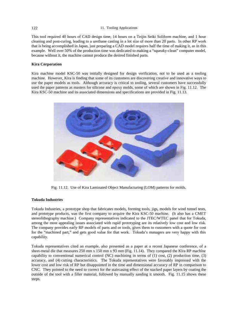
11. Tooling Applications122
This tool required 40 hours of CAD design time, 14 hours on a Teijin Seiki Soliform machine, and 1 hourcleaning and post-curing, leading to a urethane casting in a lot size of more than 20 parts. In other RP workthat is being accomplished in Japan, just preparing a CAD model requires half the time of making it, as in thisexample. Well over 50% of the production time was dedicated to making a “squeaky-clean” computer model,because without it, the machine cannot produce the desired finished parts.
Kira Corporation
Kira machine model KSC-50 was initially designed for design verification, not to be used as a toolingmachine. However, Kira is finding that some of its customers are discovering creative and innovative ways touse the paper models as tools. Although accuracy is critical to tooling, several customers have successfullyused the paper patterns as masters for silicone and epoxy molds, some of which are shown in Fig. 11.12. TheKira KSC-50 machine and its associated dimensions and specifications are provided in Fig. 11.13.
Fig. 11.12. Use of Kira Laminated Object Manufacturing (LOM) patterns for molds.
Tokuda Industries
Tokuda Industries, a prototype shop that fabricates models, forming tools, jigs, models for wind tunnel tests,and prototype products, was the first company to acquire the Kira KSC-50 machine. (It also has a CMETstereolithography machine.) Company representatives indicated to the JTEC/WTEC panel that for Tokuda,among the most appealing issues associated with rapid prototyping are its relatively low cost and low risk.The company provides early RP models of parts and or tools, gives them to customers with a quote for costfor the “machined part,” and gets good value for that work. Tokuda’s managers are very happy with thiscapability.
Tokuda representatives cited an example, also presented as a paper at a recent Japanese conference, of asheet-metal die that measures 250 mm x 150 mm x 93 mm (Fig. 11.14). They compared the Kira RP machinecapability to conventional numerical control (NC) machining in terms of (1) cost, (2) production time, (3)accuracy, and (4) cutting characteristics. The Tokuda representatives were favorably impressed with thelower cost and low risk of RP but disappointed in the time and dimensional accuracy of RP in comparison toCNC. They pointed to the need to correct for the staircasing effect of the stacked paper layers by coating theoutside of the tool with a filler material, followed by manually sanding it smooth. Fig. 11.15 shows thesesteps.
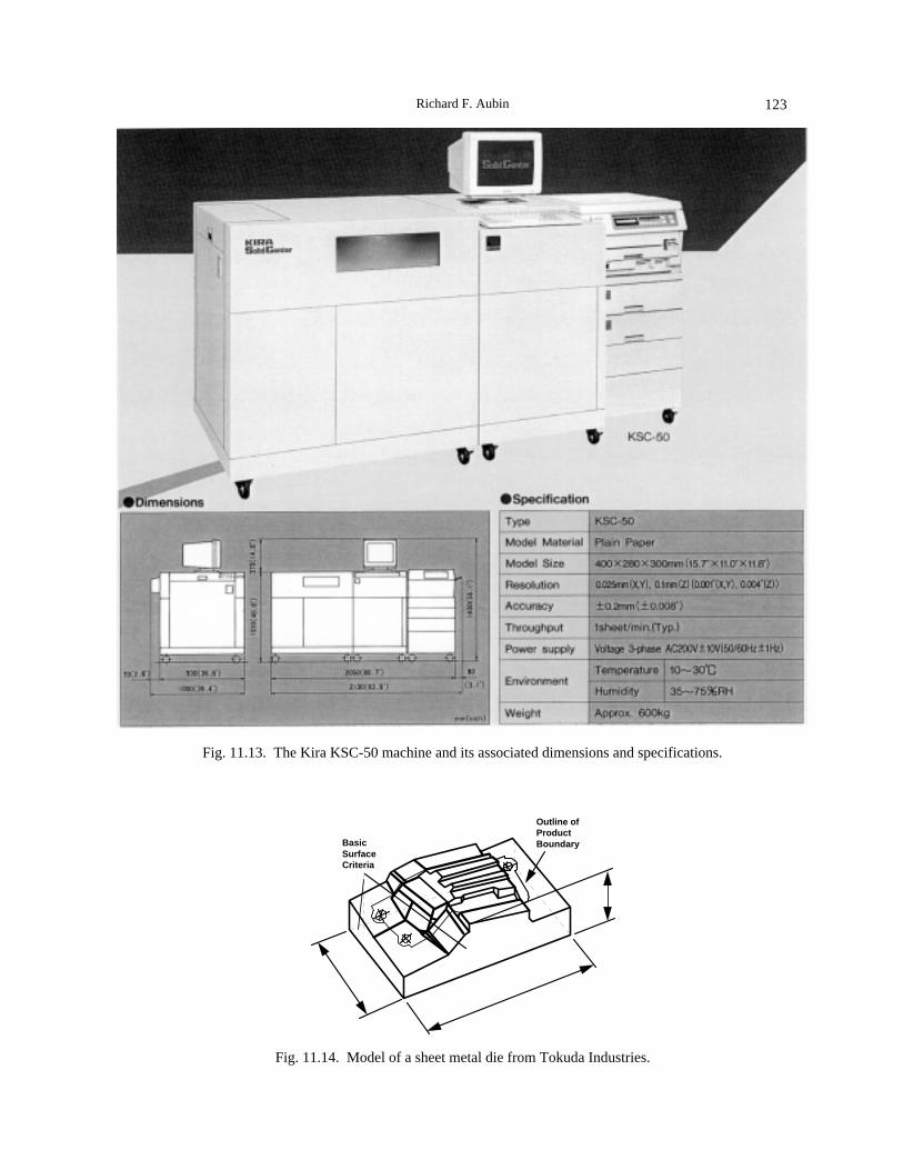
Richard F. Aubin 123
Fig. 11.13. The Kira KSC-50 machine and its associated dimensions and specifications.
Outline ofProductBoundaryBasic
SurfaceCriteria
Fig. 11.14. Model of a sheet metal die from Tokuda Industries.

11. Tooling Applications124
Material Coating
Sand Smooth Resin Coating
Fig. 11.15. Tokuda’s steps to improve staircasing surface finish.
Fig. 11.16 compares the Laminated Object Manufacturing (LOM) with CNC machining in terms of cost andtime. The cost of using the Kira process in comparison to CNC machining is less; however, the Kira RPprocess is slower.
5
3
0
3
5
4 8 12 16
Initial Outing
N/C Data Generation
Accumulated Paper Layering
N/C Processing
Manual Processing
Conventional Method
Time
Surface Processing
STL Conversion
Rapid Prototyping Method
Cost Comparison
Fig. 11.16. Time and cost comparison of Kira LOM to CNC machining.
The JTEC/WTEC panel found many examples where the Japanese are focused on dimensional accuracy andconsequently rely on CNC machining over RP approaches. The expected accuracy of the Kira process wasnoted to be within ±0.1 mm, which is not acceptable for tooling applications. Further, the dimensionalaccuracy in the stacked layers or z dimension is subject to swelling from humidity, leaving RP with muchneed for improvement.

Richard F. Aubin 125
INCS
At INCS, a very successful service bureau that is doing very well with its 3D Systems stereolithographyapparatus (SLA), a variety of applications are underway (see also Fig. 11.17): rapid tooling via QuickCast(7%); investment casting (15%); vacuum casting silicone and epoxy molds (22%); and design verification(56%). Company representatives indicated they would like to do more in the area of tooling, but they arerequired to create the computer modeling behind the scenes for a lot of their customers. About 80% of theautomotive and electronics companies in Japan use CAD, but they present the CAD model in a 2D form fromdrawings, not in a 3D model; therefore, essentially the whole modeling effort has to be redone before it canbe used for rapid prototyping.
y
QuickCast7%
Investment Casting
15%
Vacuum casting, silicone and epoxy molds
22%
Design Verification
56%
Fig. 11.17. Makeup of rapid prototyping activities at INCS.
INCS has demonstrated the ability to create rapid metal tooling, as in the brass electronic connector shown inFig. 11.18. Fabricating metal tooling for an electronic connector would normally take about 1.5 months byconventional means, because of the time required to fabricate the pinholes of the connector and the individualpins. A process was used to fabricate multiple insert pins as one assembly by plaster casting astereolithography QuickCast master pattern.
Fig. 11.18. Brass connector made by plaster casting at INCS.

11. Tooling Applications126
In the method used by INCS (see also the schematic shown in Fig. 11.19), the original 3D model data of anindividual insert pin is combined into one assembly of multiple pins using 3D CAD. Then a positive SLAmodel of the entire assembly is built, which is used as a master pattern to make a negative silicone rubbermold. Another type of silicone rubber is poured into the previously prepared negative rubber mold to form asilicone rubber part of the same positive geometry as the master SLA pattern. A plaster mold is then createdaround this silicone pattern. The silicone pattern is removed and metal is cast into the cavity. The resultingpart has the same geometry as the original SLA pattern. The choice of metal to be ultimately used forfabricating the insert pins depends on the temperature tolerance of the plaster and the required metal toolingstrength. For the electrical connector, a high grade of brass was chosen. The desired metal pins are thenfinally assembled by integrating them into the previously formed connector in one-third the time required byconventional methods.
Fig. 11.19. Plaster casting process for rapid metal tooling.

Richard F. Aubin 127
Omron
The JTEC/WTEC panel encountered the RP cultural acceptance issue again at Omron. The Omronrepresentatives expressed their belief that in five years rapid machining will dominate, while rapidprototyping will incrementally advance and continue to be restricted to design use.
Olympus Optical Company
Many camera parts that Olympus makes are very complicated. The company is creating RP models andfinishing them to make them look “real.” Looking at one of Olympus’ RP camera housings or video cameras,it is hard to believe, except when you look on the back side, that it is an RP model, because it is all sanded,painted, and looks very authentic. Panelists did not see any rapid prototype tooling applications per se, butcertainly found many examples of functional testing — up to 80% of its applications are tested usingstereolithography models. Olympus is eliminating a lot of tooling rework by going this way. That is the flipside of tooling applications: if tooling rework can be avoided, much time, energy, and cost will be saved.Table 11.1 compares resources used to make a camera case by conventional and RP techniques.
Table 11.1Olympus — Comparison of Resources Used in Making Camera Cases
ProcessNumber of
peoplerequired
Days toprepare N/Cprogram or
CAD file
Days tomachine or
make sampleDays to clean
up sample Total days
ConventionalMachining 5 10 4 0 14
Stereolithography 2 7 3 1 11
Hino Motors, Ltd.
RP applications at Hino Motors are predominantly in design verification and interference checking. HinoMotors also uses prototypes in engine research and development on the intake side of its engines for short-runfunctional testing. The company is also finding that it can check design geometry for items such as aninstrument panel air vent, in which example there was a significant time savings: checking the vent in the RPsample took 4 hours compared to the usual 2 weeks that would have been required if testing a manuallyconstructed wooden model of the air vent.
Shonan Design Company
Shonan also uses RP primarily for design verification. Its designers have coined the term, “CAM-less” for itsinjection molds. That is really synonymous with what is going on in Germany, where designers are makingthe cavity and core of the mold inserts directly, using a computer model and RP. Shonan uses some of thefilled resins from Teijin Seiki to produce mold inserts directly using a stereolithography process; however,because the resins have low thermal conductivity, Shonan representatives indicated that they are realizing a 1-2 minute cycle time for part production that used to take seconds. Consequently, they confirmed that researchis underway to add conductive fillers in the resin for the mold inserts. There was no direct metal moldactivity at Shonan Design Company at the time of the JTEC/WTEC visit.
Japan Aviation Electronics (JAE)
Besides doing functional testing, JAE makes use of rapid prototyping to visualize several of its connectorparts. By iterating and using special procedures, such as beam width compensation, thin slice layers, andshrinkage compensation, JAE is finding ways to get the best accuracy from its RP equipment. JAE is able to

11. Tooling Applications128
attain a dimensional accuracy of ±0.1 mm. The company is realizing a very significant advantage in time andcost savings. Its next step is to model some of its mold core pins to speed mold development.
Toyota
The JTEC/WTEC panelists were unable, because of time constraints and a very structured agenda, to discusstooling applications with Toyota representatives; however, the panel is aware that there is some work ongoingat Toyota. Toyota representatives did confirm a couple of RP issues that are of concern to them, most ofwhich are identified elsewhere in this study. In addition, Toyota is pursuing studies of birefringence forphotoelasticity and development of transparent parts, so designers can look through them to observe coloredgasses for evaluation purposes.
SUMMARY
From everything the JTEC/WTEC panel saw in Europe, it is evident that the infrastructure that is beingdeveloped in Germany is worth watching, and perhaps something for U.S. universities and industries to getinvolved in. Panelists were actively invited to participate in the Fraunhofer RP program. With the qualityand quantity of the infrastructure that is being put in place, a great deal of R&D can be expected from thisprogram.
In Japan, there remains a broad propensity to compare RP to CNC; however, there are some exceptions. Thetooling applications with filled resins underway at Teijin Seiki and Shonan Design certainly represent anapproach that is going to mature and eventually catch on. Also, the tooling examples cited at INCS areexcellent. To some degree, the Japanese reluctance to quickly change to RP technologies is due to theirexpert know-how and significant financial investment in numerical control machines: NC works well forthem.
Another issue slowing RP acceptance by the Japanese is the relative lack of 3D computer modelingcapability. In talking to the attendees at the 1995 Japanese Association of Rapid Prototyping Industry (JARI)conference, this author found the proliferation of 3D CAD in Japan to be very low in comparison to that ofthe United States (see also Chapter 8). This is a critical issue that Professor Nakagawa brought up when heconfirmed that as a country “Japan needs to find ways to get 3D CAD in the workplace.” Several Japaneseservice bureau representatives confirmed that over half of the time they dedicate to RP is in creating 3D CADmodels from their customers’ 2D drawings.
REFERENCES
Sites. 1996. This reference designates the companion volume to this JTEC/WTEC report: Prinz, F. B., ed.JTEC/WTEC panel report on rapid prototyping in Europe and Japan. Vol. II. Site reports. Baltimore,MD: Loyola College. NTIS Report #PB96-199583.
SME/RPA. 1996. Rapid prototyping and manufacturing ’96. Proceedings of the April 23-25 conference,sponsored by the Society of Manufacturing Engineers (SME) and the Rapid Prototyping Association(RPA), held in Dearborn, Michigan.

129
CHAPTER 12
MEDICAL APPLICATIONS
Allan J. Lightman
INTRODUCTION
Rapid prototyping is having an impact in several areas related to health care. Surgical planning and thefabrication of prostheses have received the greatest prominence, in part due to the dramatic nature of theapplication. RP systems are key to developing new modalities in other areas of use, such as specialized drugdelivery carriers. Surgical applications represent the majority of the activities in Europe and Japan, althoughthere are other applications being pursued.
In the early 1970s, a new mode of X-ray imaging was developed based upon tomographic scanning(computerized tomography, or CT). This modality differs from traditional X-ray shadowgraphy in keyaspects, including the fact that linear images are collected along one plane of the object at a time. Theseimages are taken from a variety of angles. The plane of interrogation is then shifted and the process repeated.The information collected for each plane is numerically analyzed to derive the spatial distribution of the X-ray densities within the plane. The information from each plane can then be put together to provide avolumetric image of the structure. Standard CT scanners achieve a resolution of 512 x 512 elements within alayer (1,024 x 1,024 capability is now available in more advanced systems). To scan organs or other regionsof interest, the patient is stepped through the measurement plane with a typical pitch of 2-3 mm. Finerscanning of selected regions can be accomplished so long as the total X-ray exposure is kept within safelimits. The numerically reconstructed X-ray density spatial distribution from each “slice” is then printed onX-ray film so that the data presented to the radiologist and/or surgeon is in traditional format (Fig. 12.1).
At about the same time as CT was demonstrated, application of nuclear magnetic resonance (NMR) as aninterrogation probe was also demonstrated. The name evolved over the years to magnetic resonanceinterferometry (MRI) and then finally to MR scanning. MR differs from CT in at least two key aspects: (1)the MR system measures the density of a specific nucleus, and (2) the measurement system is volumetric(interrogation of the entire body, within the measurement volume, is done all at one time). Typically, the MRsystem is tuned to hydrogen, a common constituent in most soft-tissue cellular matter. It is assumed that thismeasurement will define the spatial locations of organs by differentiating them according to the densities ofhydrogen within their tissues. The system can be tuned to other nuclear species, so long as the nucleus has amagnetic moment (that is, an odd number of protons and/or neutrons). As a result of the diagnostician’sfamiliarity with interpreting CT scan data, MR scan data is also computed and presented in a layer-by-layerformat.

12. Medical Applications130
Fig. 12.1. CT section of a skull. X-ray density is mapped to gray scale (University of Dayton).
These two systems, CT and MR, present the finest resolution capability available in diagnostic systems,achieving volumetric resolutions of about 2 mm in each direction. More recently, spiral-scan CT has beendeveloped. In this modality, X-ray data is collected circumferentially as the patient is continuously movedthrough the scanner. This spiral data collection path provides partial data at every location along the scan.Using interpolation algorithms, a complete scan can be put together at any desired plane, yieldingreconstructed slices at considerably finer spacing than stepping systems achieve. The numerical analysis isthought to be more robust, due to availability of the partial data at every plane. Validation tests usingphantoms are still underway. Currently, users of spiral-scan CT are claiming isotropic resolution of 0.5 mmor better. Data from other scanning systems (PET, SPECT, etc.) are considerably more coarse. Their outputis also presented in a layer-by-layer format.
The information from CT scanner systems provides a host of potential medical applications. Detailedinformation can be electronically shared among practitioners, thus permitting distributed consultation. Thisform of telemedicine is providing expert assistance in remote locations. Another application gainingwidespread use is the creation of virtual images of the constituents mapped in the images. Full three-dimensional geometry can be assembled from the data. These images can then be formed into stereoscopicpresentations viewed from the perspective of a designated platform, providing the equivalent of a “fly-through.” These same images, in a static format, can be presented to surgeons during operations, using“heads-up” displays, to guide them (that is, computer-assisted surgery, or CAS). The images are oriented bythe use of registration fiducials, located on the patient and visible in the image, and a tracker determining thesurgeon’s location and view angle relative to the patient. In addition, this layer data format presents a readypath to control current RP systems, which also function on a layer-by-layer basis. This potentialtransformation was recognized early in RP development, and accurate anatomical RP models were fabricated.This physical realization of CT data has been termed “real virtuality.”
These technologies may be able to significantly impact the cost of medical care. Budget demands are placingconsiderable emphasis on field evaluation. The focus in the United States is on telemedicine and CAS. It isthought that these technologies will have a significant monetary impact. The use of telemedicine is especiallyimportant, due to the large physical size of the United States and the difficulty of providing highly trainedphysicians and surgeons at remote sites. Europe is smaller in size and Japan is much smaller, so issues ofdistance are less significant there. Telemedicine is still receiving attention, in part due to the application ofthe same technologies to electronic archiving of patient files. CAS and the application of RP models areunder strong development in both regions. There is also a significant effort in Australia in applying RPmodels for surgical planning. CAS and RP are viewed as complementary, and the RP models offer theadvantage of providing stereotactic feedback to the surgeon. Also, the RP models provide a medium forpractice efforts; the results can be taken into the surgical theater and used as templates. Furthermore, in
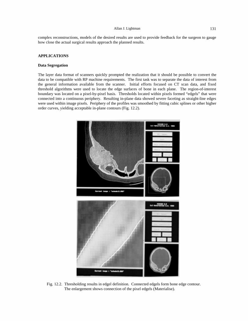
Allan J. Lightman 131
complex reconstructions, models of the desired results are used to provide feedback for the surgeon to gaugehow close the actual surgical results approach the planned results.
APPLICATIONS
Data Segregation
The layer data format of scanners quickly prompted the realization that it should be possible to convert thedata to be compatible with RP machine requirements. The first task was to separate the data of interest fromthe general information available from the scanner. Initial efforts focused on CT scan data, and fixedthreshold algorithms were used to locate the edge surfaces of bone in each plane. The region-of-interestboundary was located on a pixel-by-pixel basis. Thresholds located within pixels formed “edgels” that wereconnected into a continuous periphery. Resulting in-plane data showed severe faceting as straight-line edgeswere used within image pixels. Periphery of the profiles was smoothed by fitting cubic splines or other higherorder curves, yielding acceptable in-plane contours (Fig. 12.2).
Fig. 12.2. Thresholding results in edgel definition. Connected edgels form bone edge contour.The enlargement shows connection of the pixel edgels (Materialise).

12. Medical Applications132
The RP models constructed were based on the coarsely spaced layer data in which a scan layer was repeatedon the RP machine until it had built up sufficient material to align with the next scan layer. The resultingstructure showed severe staircasing. Overcoming this problem has been a focus of both the European andJapanese programs. Several approaches lead to smoothing of the staircasing. The data between scan layerscan be approximated by “morphing” from one layer to the next. Critical transformation locations must bespecified. The result will be a smoother profile with a discontinuity at each layer, which can also besmoothed out by fitting splines in the vertical dimension. The results provided data that led to RP models thathad excellent appearance and were accurate anatomical models of structures with significant cortical bone,the dense bone structure in the outer areas of heavier bones (Swaelens and Kruth 1993).
Although scan data is typically presented in a two-dimensional format, the film density assigned to a pixel is ameasure of the average density measured throughout a volume element (voxel). Consequently, the assigneddensity associated with the center location of the pixel may actually more closely represent the value at alocation on a plane above or below the scan plane. This spatial displacement needs to be taken into accountwhen constructing more accurate models and models with highly figured surface profiles, such asmaxillofacial, jaw and tooth, spine, and fine-boned joints of the hand and foot. Another complication thatarises in modeling these structures is that when the thickness of the bone structure is smaller than the aperturewindow for the scanner, the average X-ray density computed for the voxel will be less than the actual bonedensity, possibly less than the threshold density of the data segregation algorithm. As a result, using fixedthreshold data segregation may result in the edgel being located too far into the bone, yielding a measurethinner than the actual bone, or, even more serious, the voxel averaged density may not be sufficient to crossthe threshold and a void artifact will be generated.
The medical modeling programs in Europe, Japan, and Australia have concentrated on the application of RPmodels for diagnostics and surgical planning. Their major effort has been in the development of models forpatient-unique structures (as opposed to hip replacements, where a limited set of variations will satisfy allcustomers). There has been a major focus on maxillofacial and craniofacial reconstruction (Fig. 12.3),jawbone replacement and augmentation, and dental implants. In addition, models of the pelvis, foot, andspine have been examined in some detail. Both the European and Japanese programs recognized thelimitations due to the straightforward data interpretation and developed higher order data reductionalgorithms that smooth out the surfaces to more closely match the patient’s actual geometry. The issue ofvariable thresholding and void artifacts is a continuing problem. The Australian program is principallyfocused on surgical applications (Fig. 12.4), mainly relying on European software. In the United States themajor thrust of RP modeling has been to hip and knee prosthetics, so current capability has adequately metmost needs.
Fig. 12.3. Osteotomy planning of reconstruction for Goldenhar syndrome patient.(Dr. B. Vanassche, Eeuwfeestkliniek, Belgium).

Allan J. Lightman 133
Fig. 12.4. (Left) A cranial trauma was modeled, along with a defect obtained by a Boolean subtractionof the defect from the mirrored, blended opposite face; (right) a biocompatible insert wasmolded from an RP master and the fit verified before surgical implantation (Dr. P. D’Urso,University of Queensland, Australia).
R&D PROGRAMS
Europe
The most significant effort applying RP to medical modeling, both in number of programs and scope of effort,is in Europe. The major focus is in the BRITE EuRAM PHIDIAS project administered by Materialise, NV(Belgium), an RP service bureau set up in the technology park on the campus of the Catholic University ofLeuven. Materialise is developing the CT/MR-to-RP interface software and building the RP models. Theproject team includes Zeneca Specialties (UK), which is developing new stereolithography resins, and manyclinics, hospitals, and university medical research groups.
Other centers focused on surgical applications of RP include: the Institute of Medical Physics at theUniversity of Erlangen-Nürnberg in Erlangen, Germany, where Professor Willi Kalender (developer of thespiral-scan CT) is focused on data interpretation and presentation; the University of Zurich, Switzerland,where Professor Stucki is also studying image analysis and presentation; and the University of Leeds, UK. Inaddition, there is a significant number of locally funded application evaluations underway throughout Europe,including in France, Austria, Denmark, Italy, and Germany.
The major advances in technology have been made in the PHIDIAS project. These include the developmentof the software that interprets the CT scan data and generates the files needed to build the models bystereolithography; the development of a two-color resin for stereolithography that permits marking thepatient’s identification into the model and designating the regions of interest; and a survey quantifying theimpact of the model when compared with traditional images.
There is also an RP medical work area specialization that is funded through the European Action on RP(EARP). There is some overlap between the work funded through EARP and PHIDIAS. One project in theEARP program that could have a major impact on the acceptance of RP medical models is the EARPDatabase Project, which is attempting to quantify the cost-benefit of using RP models in terms of dollarssaved, surgical hours saved, enhanced patient service, and speeded recovery. One goal is to be able to justifyinsurance coverage of the model-making procedure. Another database measuring the effectiveness of RPmodels has been constructed by Smet (1995) as part of the PHIDIAS project.

12. Medical Applications134
The European projects are sufficiently mature to lead to regular conferences focused on the medicalapplications areas. These include the biannual International Workshop on Rapid Prototyping in Medicine andthe annual PHIDIAS Workshop on Stereolithographic Modelling.
Japan
The major program in Japan is focused through INCS, Inc., a Tokyo-based service bureau, and a consortiumof six university medical programs. Their main focus is on the creation of models for surgical planning. Inaddition, INCS is developing software that will provide smoother, more accurate models from the scan data.Its results are not as well publicized as those of the European programs. In addition, there is at least one otherproject underway, at Hokkaido University, focused on dental implants and tooth repair. INCS has made acranial implant in ceramic apatite on a multiaxis milling machine. The data was developed using symmetry inthe CT-scan data to cover the defect in the skull. The prosthetic was verified by placing it on the RP model ofthe patient. It was surgically implanted, verifying the accuracy of the procedure. This was done inconjunction with Keio University. Some of the results have been published (Lightman et al. 1995).
Australia
The Australian program is directed by a neurosurgeon, Paul D’Urso, MD, PhD (University of QueenslandDepartment of Surgery, Brisbane), who also has expertise in the engineering and computer aspects of RP.The impressive results illustrate the importance of having surgeons pulling the technology rather thanengineers pushing it. Dr. D’Urso’s surgical team has used RP models in more than 70 surgeries, and theynow rely almost exclusively on the RP models, rather than on the CT scan data, for surgeries where RPmodels apply. D’Urso uses the Materialise software to convert the scan data for stereolithography modelfabrication. His focus has been on the use of the models for both surgical planning (Fig. 12.4) and fabricationof surgical tools.
United States
The major effort in the U.S. programs has been the fabrication of hip and knee replacements. By and large,these units are produced in standard configurations and sizes and stocked as commodity items. There hasbeen limited application of the unique RP models needed for reconstruction surgery and similar applications.There are activities ongoing at centers of research such as the University of Dayton (Ohio); Laserform, Inc.(Michigan), which is working in association with Materialise; Bowling Green State University (Ohio);UCLA; and the Prosthodontics Department of the USAF Medical Center, Lackland AFB. Recently,Materialise opened a U.S. office in Michigan. The U.S. effort is small and there is no central coordination atthis time, reflective of the federal government funding being focused almost exclusively on telemedicine andCAS.
OTHER RP APPLICATIONS TO MEDICINE
While the major medical applications of RP technology are related to surgery, there are other applicationswith the potential to significantly impact health care delivery. (The primary focus of the programs that thepanel reviewed outside the United States was surgical applications.) There is an effort in Germany to uselaser caving to create a surface structure that will promote bone growth and integration of the prosthesis. Inthe United States, MIT is studying applications of its Three-Dimensional Printing (3DP) process to thegeneration of controlled patterned surfaces, which can be applied for prosthesis retention. The capability isalso being explored for holding metered amounts of medication in a conveyance that has timed releaseencapsulation, providing an assured medication supply.

Allan J. Lightman 135
CONCLUSIONS
The use of RP models for surgical planning is making rapid strides outside the United States. Initial resultsindicate that RP models can provide unique capabilities in specific applications. Programs are principallyfocused on complex surgeries, where an anatomically accurate model can significantly impact diagnostics,planning, patient counseling, and performance of the procedure. RP models are used where the procedurerequires detailed knowledge of the patient’s unique anatomical characteristics. Programs in both Europe andJapan are focused on improving the accuracy of the data analysis of the images produced by tomographicscanners. The European program to quantify the benefit of using RP models should provide the concretestatistics needed to present to insurance companies to justify their consideration of this procedure as acovered expense. The U.S. programs are extremely limited. Other medical applications for RP are emerging,and their impact will grow.
REFERENCES
An overview of the global activity can be obtained by studying the subject titles and research sites for thework reported at the biannual International Workshop on Rapid Prototyping in Medicine & Computer-Assisted Surgery, Erlangen, Germany.
Lightman, A. J., B. Vanassche, P. D’Urso, and S. Yamada. 1995. Applications of rapid prototyping tosurgical planning: A survey of global activities. In Proceedings of the Fifth International Conference onRapid Prototyping, Dayton, OH.
Materialise. World Wide Web homepage, http://www.materialise.com
Smet, M. H., et al. 1995. Quality requirements and validation of medical models. Paper presented at the 3rdIntl. Workshop on Rapid Prototyping in Medicine & Computer-Assisted Surgery in Erlangen, Germany.
Swaelens, B., and J. P. Kruth. 1993. Medical applications of rapid prototyping techniques. In Proceedingsof the Fourth International Conference on Rapid Prototyping, Dayton, OH.

12. Medical Applications136

137
APPENDICES
APPENDIX A. PROFESSIONAL EXPERIENCE OF PANEL MEMBERS
Fritz B. Prinz, Panel Chair
Affiliation: Stanford UniversityAddress: Departments of Mechanical Engineering and Materials Science and Engineering
Building 530, Stanford, CA 94305-3030
Professor Prinz, the Rodney H. Adams Professor in the School of Engineering and professor in theDepartments of Mechanical Engineering and Materials Science Engineering, is also co-chair of StanfordIntegrated Manufacturing Association (SIMA). He received his PhD (physics, 1975) from the University ofVienna, Austria, and in 1977 he was awarded a Fulbright-Hays Visiting Fellowship for research at theMassachusetts Institute of Technology. He was professor in the Department of Mechanical Engineering atCarnegie Mellon University (1989-1994), and also Director of the Engineering Design Research Center, aNational Science Foundation research center. His current research activities address a wide range ofproblems related to intelligent design, rapid prototyping, and manufacturing. He has served on the followingNational Research Council committees: Research Priorities for U.S. Manufacturing, Improving EngineeringDesign, Joint U.S.-Japan Study Mission on Manufacturing, Opportunities for Computer Aided DecisionSupport Tools in Materials Selection.
Clinton L. Atwood
Affiliation: Sandia National LaboratoriesAddress: P.O. Box 5800, MS 0958, Albuquerque, New Mexico 87185
Mr. Atwood is the Rapid Prototyping Team Leader at Sandia National Laboratories, He has worked at Sandiafor 20 years (manufacturing). Prior to his work in rapid prototyping he supervised the Heavy MachiningSection, Miniature Machining Section, and Machinist Apprentice Section at Sandia. He has been active inthe advancement of several rapid prototyping (RP) technologies. Activities include alpha and beta testing ofpreproduction machines, testing new software and hardware, and participation in technical advisory groupsand user groups. He is an active member of the Board of Advisors for the Society of ManufacturingEngineers Rapid Prototyping Association (RPA/SME) and a member of the 1996 RPA/SME conferenceplanning committee. He is the recent past chairman of the North American Stereolithography Users Group.In addition, he participates in the Selective Laser Sintering (SLS) Technical Associates Group at theUniversity of Texas, and in the SLS Users Group. He has authored and presented several papers on theintegration and applications of rapid prototyping technologies in manufacturing.
Richard F. Aubin
Affiliation: Manager, Rapid Manufacturing, United Technologies Research CenterAddress: United Technologies Research Center
411 Silver Lane MS 129-48, East Hartford, CT 06108
Mr. Aubin’s 27 years experience at United Technologies Corporation (UTC) included manufacturingassignments in tool and die making, inspection, and numerical control programming. He was responsible forthe stereolithography installation at Pratt & Whitney’s East Hartford facility. He initiated a group that

Appendix A. Professional Experience of Panel Members138
supports the rapid prototyping needs of other divisions of UTC. While in this capacity, he initiated betatesting programs of emerging rapid prototyping technologies. He was the coordinator for UTC consortiumprograms with MIT, Carnegie Mellon University, and the University of Texas. Aubin was a CoordinatingPartner in the Intelligent Manufacturing Systems (IMS) Rapid Product Development Program. He authoredseveral publications on rapid prototyping and related topics. Mr. Aubin was a founding member of theAdvisory Board for the Rapid Prototyping Association of SME and was on the editorial review board for theRapid Prototyping Journal. He was awarded a BS in Business Management from the University of Hartford.
Joseph J. Beaman
Affiliation: Andersen Consulting Endowed Professorship in Manufacturing Systems EngineeringAddress: Department of Mechanical Engineering
University of Texas at Austin, Austin, TX 78712-1063
Professor Joseph J. Beaman joined the UT faculty in 1979 after receiving his doctorate at the MassachusettsInstitute of Technology in the Mechanical Engineering Department. Dr. Beaman is presently Director of theSolid Freeform Fabrication Laboratory. He has been coorganizer of the Annual Solid Freeform FabricationSymposium since the first symposium in 1989. He received the first National Science FoundationPresidential Young Investigator Award in 1984. He has published numerous articles related to his researcharea. He is also a founder of DTM Corporation, an industrial concern commercializing Selective LaserSintering. Between January 1988 and October 1991, he was Area Coordinator for the Mechanical Systemsand Design Area. He is a member of the Texas Society of Professional Engineers and the American Societyof Mechanical Engineers, and has served on the ASME Executive Committee for the Dynamic Systems andControl Division. He was Chairman of this ASME technical division from 1994-1995. He has receivednumerous grants from both government and private sources.
Robert L. Brown
Affiliation: The Gillette CompanyAddress: Prudential Tower Building 49th Floor
Boston, MA 02199
Mr. Brown, Director of External Technology for the Gillette Corporate R&D Laboratories, is responsible foridentifying and acquiring new technology to support the various product and process lines of Gillette.Besides the blade and razor divisions, other product lines include Braun, AG (personal appliances), Oral-B(oral care products), Stationary Products (including PaperMate, Parker, Liquid Paper and Waterman), and thevarious toiletries groups. Previously he was Director of Advanced Process and Control R&D and wasresponsible for developing concepts for high-volume, high-speed manufacturing. He also has engineeringmanagement experience in process development for electronic materials and steelmaking at TexasInstruments and Teledyne. He is one of the founders of the Society of Manufacturing Engineers (SME)Rapid Prototyping Association (RPA) and currently serves on the advisory board of RPA. He graduated fromMichigan Technological University (BS) in metallurgical engineering and from MIT (SM, ScD) in physicalmetallurgy. He also has an MBA in accounting and finance from Boston University.
Appendix A. Professional Experience of Panel Members 139
Paul S. Fussell
Affiliation: Senior Technical Specialist, Aluminum Company of America (Alcoa)Address: Alcoa Technical Center
Alcoa Center, Pennsylvania, 15069-0001
Dr. Fussell is responsible for rapid prototyping at Alcoa. He has been with Alcoa for ten years working onresin-based and metal-spraying rapid prototyping, and on downstream processes for rapid generation of metaltools. He is Alcoa’s liaison to university research groups, particularly those at CMU, Stanford, and MIT. Heis also a program manager in the area of efficiently relating part measurement data to the desired shape (e.g.,the CAD database). Formerly he worked in areas of robot controller design and robotic welding processintegration. He received a PhD in Mechanical Engineering from Carnegie Mellon University, writing a thesisentitled “Sprayed Metal Shells for Tooling: Phenomenology, Microstructures, and Properties.” He is amember of the honorary organizations Sigma Xi, Tau Beta Pi, and Pi Tau Sigma, and he has authored or co-authored over twenty-eight papers, grants, and patents.
Allan J. Lightman
Affiliation: Senior Research Scientist, University of Dayton Research InstituteAddress: University of Dayton Research Institute
300 College Park, Dayton, OH 45469-0150
Dr. Lightman conducts research and development on technologies and materials for rapid product realization.He cofounded the Rapid Prototype Development Laboratory (RPDL) at the University of Dayton and theannual International Conference on Rapid Prototyping. He is a member of the editorial board of theInternational Journal of Rapid Prototyping, and he was a founding member of the board of the RapidPrototyping Association of SME. His current RP research focuses on new materials development (ceramicsand high-temperature photopolymers) and on applications of RP technology for surgical planning and othermedical diagnostics. He reviews RP technology development and implementation worldwide and reports hisfindings to a variety of industry and government sponsors.
Emanuel Sachs
Affiliation: Associate Professor of Mechanical Engineering, Laboratory for Manufacturing andProductivity, MIT
Address: Department of Mechanical Engineering, Cambridge, MA 02139
Dr. Sachs’ specialty is flexible manufacturing, with a primary emphasis on the development of the Three-Dimensional Printing Process, of which he is a coinventor and coprincipal investigator. He is also known forwork in the area of Process Control of VLSI fabrication. Prior to joining the faculty, he spent seven yearsworking in the field of photovoltaics (solar cells), two years at Mobil-Tyco Solar Energy Corp, and five yearsat Arthur D. Little, Inc. He is the inventor of the Edge Stabilized Ribbon Growth method for making low-cost substrates for solar cells. This technology was developed at MIT and Arthur D. Little and is now beingcommercialized by Evergreen Solar, Inc. of Waltham, MA. Dr. Sachs is the author or coauthor of more than70 technical papers and is listed as the inventor or coinventor on more than 20 patents. He was awarded theBS (1975), MS (1976), PhD (1983, Mechanical Engineering) from MIT. He was a Hertz Fellow and earnedthe Hertz Foundation Doctoral Thesis Prize in 1983. Together with coworkers, he was awarded an IR&D100 award in 1994.

Appendix A. Professional Experience of Panel Members140
Lee E. Weiss
Affiliation: The Robotics InstituteAddress: Carnegie Mellon University
217 Smith Hall, Pittsburgh, PA 15213
Dr. Weiss is a Senior Research Scientist in the Robotics Institute and the Biomedical Engineering Programand is the Director of the Design and Manufacturing Laboratory of the Engineering Design Research Centerat Carnegie Mellon University (CMU). He has a bachelor’s degree in electrical engineering from theUniversity of Pittsburgh and a master’s degree in bioengineering and a PhD degree in electrical and computerengineering from CMU. He was the first graduate student in the Robotics Institute. There he has designedand implemented several systems, including robotic assembly cells, intelligent robot end-effectors, anautomated computer vision station for solder joint inspection, an adaptively controlled direct-drive robot arm,a robot leg for a Mars Rover autonomous walking machine, a rapid tool manufacturing system based onthermal spraying, and the Shape Deposition Manufacturing facility. He has 17 patents and is the author ofover 50 technical papers.
Michael J. Wozny
Affiliation: Rensselaer Polytechnic InstituteAddress: Center for Advanced Technology
Rensselaer Polytechnic Institute, CII 8015, Troy, NY 12180-3590
Dr. Wozny has just returned to his professorship at Rensselaer Polytechnic Institute after a leave of absenceserving as Senior Advisor to the Undersecretary of Commerce for Technology, dealing with manufacturingcompetitiveness issues. He established and directed the Design Research Center at Rensselaer for 16 years.He was a laboratory director at National Institute of Standards and Technology (1994-95); senior fellow atIndustrial Technology Institute (1991); a division director at the National Science Foundation (1986-88); andresearcher at General Motors Research Laboratory (1972). He established, helped plan, and participated inthe U.S.-Japan Technical Exchange Forums in Manufacturing (1988, 1990), coordinated by the NationalResearch Council. He has worked in computer graphics, computer-aided design, rapid prototyping andmanufacturing. He is chairman of the International Federation for Information Processing (IFIP) workinggroup 5.2 (CAD), and he has received the IEEE Centennial Medal (1984), and the National ComputerGraphics Association Academic Award (1988).

141
APPENDIX B. PROFESSIONAL EXPERIENCE OF OTHER TEAM MEMBERS
Kesh Narayanan
Affiliation: Program Director, Design, Manufacturing, and Industrial InnovationAddress: National Science Foundation
4201 Wilson Blvd., Arlington, VA 22230
Dr. Narayanan is currently the program director overseeing research interests in the area of machines andmanufacturing processes at NSF. He is charged with the identification of leading edge technologies andencouraging innovative research ideas in materials processing. Prior to coming to NSF in 1994, he was theChief Scientist at Certainteed, a building materials company. His duties included leveraging research resultsfrom the academic world and applying them to the business. His longest tenure was at Norton Company,spanning 20 years. As the R&D Director of Norton Abrasives Business, he led the worldwide introduction ofnew products with a track record of new products accounting for more than 25% of total sales. Innovationsincluded new materials such as seeded sol-gel Alumina, novel polymer compositions for bonding ofabrasives, introduction of high-speed cut-off wheels, and many more covering the area of manufacture anduse of grinding wheels. His department is credited with over 30 patents. He received his PhD (MaterialsScience and Engineering) from Carnegie Mellon University in 1974 and his BS from the Indian Institute ofTechnology.
Robert Duane Shelton
Affiliation: Loyola CollegeAddress: Dept. of Computer Science, Loyola College
4501 N. Charles St., Baltimore, MD 21210-2699
Dr. Shelton received his degrees in electrical engineering from Texas Tech, MIT, and the University ofHouston. He has been a professor at the University of Houston and Texas Tech, and at the University ofLouisville, where he was Chairman of the Applied Math and Computer Science Department. He has alsoworked as an engineer at Texas Instruments, at NASA on the Apollo space communications system, and atthe National Science Foundation as a science policy analyst. He has served as principal investigator on over25 grants and contracts totaling over $2 million. He is presently professor of engineering and computerscience at Loyola College in Maryland. He is also Director of the International Technology ResearchInstitute at Loyola, which assesses foreign technologies on behalf of the National Science Foundation, NASA,the Department of Energy, DARPA, ONR and the Department of Commerce.
Cecil H. Uyehara
Affiliation: President, Uyehara International AssociatesAddress: Uyehara International Associates
7614 Arnet Lane, Bethesda, MD 20817
Cecil H. Uyehara is a consultant in the Washington DC area on U.S.-Japanese relations in science andtechnology fields. He served in the U.S. government for almost 25 years, with the Air Force (weaponssystems planning), the Office of Management and Budget (military assistance) and the Agency forInternational Development (AID). He has published books and articles on Japanese politics, scientific adviceand public policy, Japanese calligraphy, and Afghan philately. He organized the first U.S. Congressionalhearings on Japanese science and technology, lectured at the U.S. Foreign Service Institute on Japanesescience and technology, and served as a consultant to the Yomiuri Shimbun and the Library of Congress on

Appendix B. Professional Experience of Other Team Members142
Japanese calligraphy. He graduated from Keio University (BA), the University of Minnesota (MA), both inpolitical economy, and received awards/grants from the Ford Foundation, American Philosophical Society,University of Minnesota (Shevlin Fellowship) and the National Institute of Public Affairs (Fellowship atHarvard University, 1963-4).

143
APPENDIX C. PARTIAL LISTING OF WORLD WIDE WEB HOMEPAGESFOR SITES VISITED BY THE PANEL(See also Chapters 7 and 8 for other relevant WWW homepages)
Bavarian Laser Center (BLZ)http://faufthp7.lft.uni-erlangen.de:8080/
Catholic University of Leuven, Division of Production Engineering, Machine Design, andAutomation (PMA ) Home page: http://www.mech.kuleuven.ac.be/pma/pma.html
Rapid prototyping: http://www.mech.kuleuven.ac.be/pma/research/95/2_2/htm
MaterialiseU.S. site (info. limited to Materialise software): http://www. materialise.com/European site (info. on all RP activities): http://www.materialise.be/
Fraunhofer Institute for Applied Materials Research (IFAM)http://www.ifam.fhg.de
Fraunhofer Institute for Manufacturing Engineering and Automation (IPA)http://www.ipa.fhg.de
University of Stuttgart, Institute for Polymer Testing and Polymer Science (IKP)http://www.ikp.uni-stuttgart.de
University of Tokyo, Prof. Kimurahttp://www.cim.pe.u-tokyo.ac.jp/index-j.html

144
APPENDIX D. GLOSSARY
3DP Three-dimensional Printing (MIT)
AFPR Association Française de Protypage Rapide (France)
AI Artificial intelligence
AOM Acousto-optic modulator
AP Application protocol
ASA Acrylnitril styrene acrylic copolymer
BIBA Bremen Institute for Industrial Technology and Applied Work Science (EU project)
BPM Ballistic Particle Manufacturing (process and U.S. company)
BRITE EuRAM Basic Research of Industrial Technologies for Europe, European Research on Advanced Materials program
CAD Computer-assisted design
CAE Computer-assisted engineering
CALS Commerce at Light Speed (Japanese R&D program)
CAM Computer-assisted manufacturing/machining
CAS Computer-assisted surgery
CAT Computed axial tomography
CBN Cubic boron nitride
CLI Common layer interface (format alternative to STL)
CMM Coordinate measurement machine
CNC Computer numerical control
CT Computed tomography (medical)
DFE Data Front End, a Cubital software package
DMEC Design Model Engineering Center (Japan)
DSPC Direct Shell Production Casting
DTM A U.S. Corporation based in Austin, TX
DTM Desktop manufacturing
EARP European Action on Rapid Prototyping
ECM Electrochemical machining
ECU European Currency Unit
EDI Electronic data interchange
EDM Electrical discharge machining
EFTP Euro File Transfer Protocol (for arbitrary partners)
EMI Electromagnetic interference
EOS Electro-Optical Systems (Germany)
EU European Union
FDM Fused Deposition Modeling (Stratasys)
FEA Finite element analysis
FEM Finite element mesh
FhG Fraunhofer Institute
HPGL Hewlett-Packard Graphics Language

Appendix D. Glossary 145
I-DEAS CAD software from SDRC in Milford, OH
IFSW Institute for Laser Technology (Stuttgart)
IGES Initial graphics exchange specification
IMS Intelligent manufacturing system
IP Intellectual property
IPR Intellectual property rights
IROFA International Robotics and Factory Automation Center
ISDN Integrated services digital network
ISO International Standards Organization
JARI Japan Association of Rapid Prototyping Industries
JSR Japan Synthetic Rubber
LAN Local area network
LANL Los Alamos National Laboratory
LEAF Layer-exchange ASCII format
LOM Laminated Object Manufacturing, trademark of Helisys (LOM-2030™)
LSI Large-scale integrated circuits
MAGICS Software, registered trademark of Materialise N.V.
MJS Multiphase jet solidification (IFAM/IPA)
MRI Magnetic resonance interferometry
NC Numeric control (machining/milling)
NMR Nuclear magnetic resonance (MRI or MR now used)
NURBS Nonuniform rational B-spline
ODETTE [OFTP] File transfer protocol for automotive industry and suppliers
pcb Printed circuit board
PCC Precision Castparts Corporation (France)
PEEK One of several super engineering plastics
PS Polystyrene
QFD Quality function deployment
RIM Reaction injection molding
RP Rapid prototyping
SAHP Selective Adhesive and Hot Press Process (Kira)
SCS Solid Creation System (Sony)
SDM Shape deposition modeling/manufacturing
SFF Solid freeform fabrication
SGC Solid ground curing (Cubital)
SHG Second harmonic generation
SL Stereolithography
SLA Stereolithography Apparatus (3D Systems)
SLP Solid laser plotter
SLS Selective laser sintering (DTM Corp.)
SME Society of Manufacturing Engineers
SOUP Solid Object Ultraviolet (laser) Plotter (CMET)
SPL Stereophotolithography

Appendix D. Glossary146
staircasing RP edge effect description
STEP Standard for the exchange of product model data
STL A computer model (CAD) file format that is rendered in triangular facets. Also called a tessellated file. [Stereolithography Text Language]
TPM An RP cleaning solution
VR Virtual reality
VRML Virtual reality modeling language
WAN Wide area network
WWW Worldwide web
WZL Machine Tool Institute of Aachen, Germany

Appendix D. Glossary 147

ISBN 1-883712-44-0