James Daly Memorial Lecture, - Home > BMCE - … · The central courtyard was to be in-filled with...
22
James Daly Memorial Lecture, 10 Trinity Square, 11 th March, 2014
Transcript of James Daly Memorial Lecture, - Home > BMCE - … · The central courtyard was to be in-filled with...
James Daly Memorial Lecture,
10 Trinity Square, 11th March, 2014
Introduction and history
History of the original building
History of project
Project team
The project
Initial works and Foundations
Ground conditions
Excavation and piling within the courtyard
The tower building
New courtyard superstructure
Seething lane
Works to existing building
investigations and material testing
existing structure and new loadings
robustness and stability
remedial work
Fourth floor structure and the upper levels
Transfer steel floor
Pre-deflection frames
Modern method of construction- The Volumetric unit
Roof
Roof structure
Conclusions
INTRODUCTION AND HISTORY
History of 10 Trinity Square
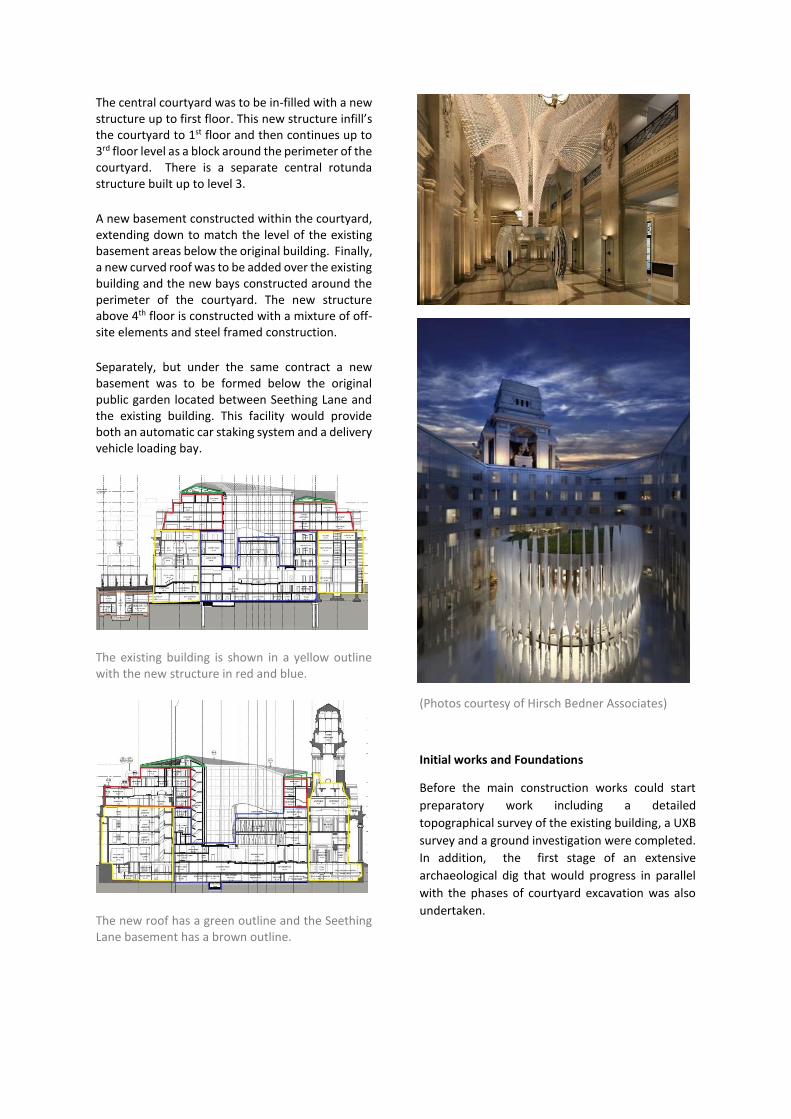
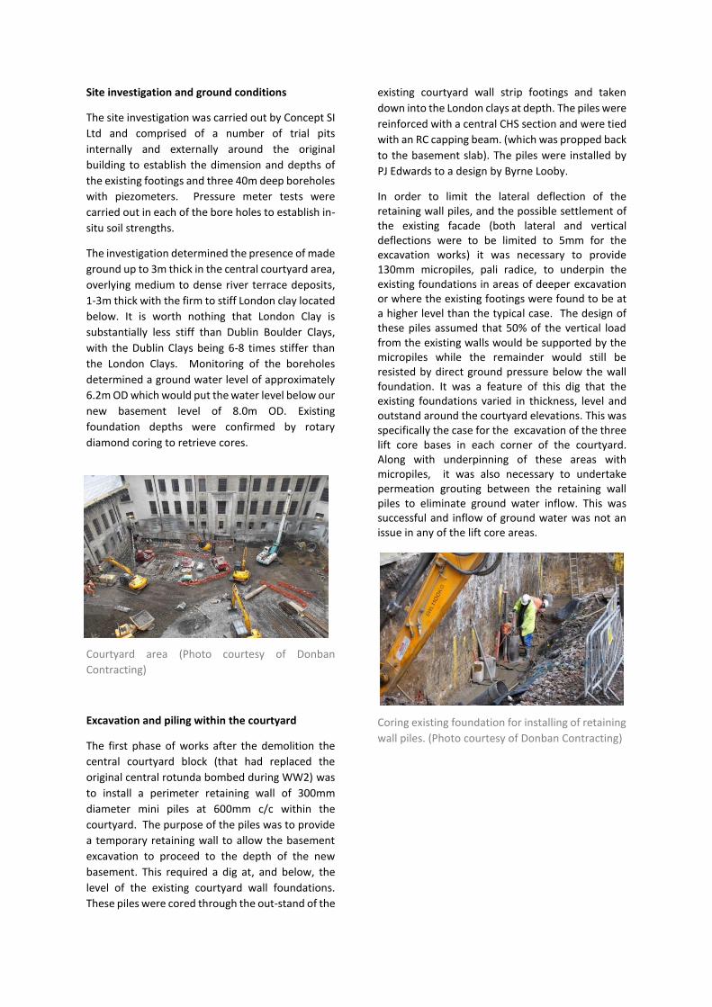
When the Port of London Authority was formed in 1900, Britain was the foremost maritime nation in the world. A prestigious building was needed to house the new authority and a site was selected overlooking the River Thames at Tower Hill, in the southeastern corner of the City of London. The architectural competition was won by Sir Edwin Cooper; construction was started by John Mowlen & Co in 1910 and completed in 1922. 10 Trinity Square was opened by David Lloyd George, the then British Prime Minister, in 1922. The building was damaged by German bombing during the Blitz in World War II with the original central rotunda being destroyed. The building is currently listed grade II* (particularly important buildings of more than special interest). One of the first meetings of the UN was held in the board room of the tower building and a more a recent claim to fame was the buildings use as a film location for the Bond movie ‘Skyfall’.
Background and scope of the project
In 2008, the vacant building was purchased by the partnership of KOP Group and Reignwood Properties, both large multi-national property developers. In 2010, Reignwood acquired sole ownership of the property and appointed a design team to develop the scheme. The plan was to create a 5 star hotel with a number of private luxury apartments in the heart of London. The client’s
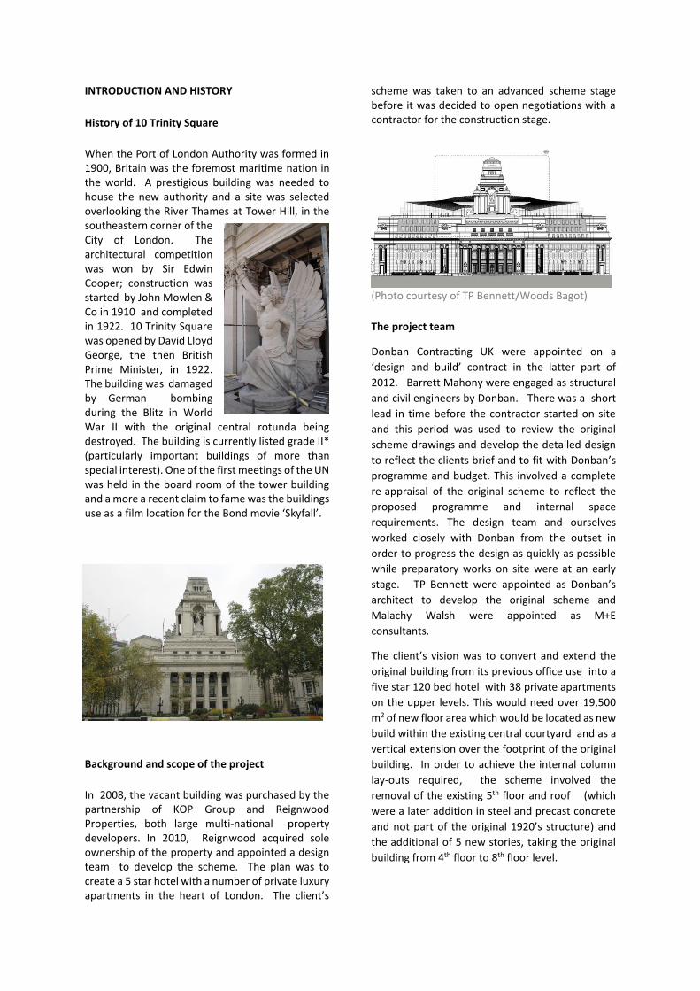
scheme was taken to an advanced scheme stage before it was decided to open negotiations with a contractor for the construction stage.
(Photo courtesy of TP Bennett/Woods Bagot)
The project team
Donban Contracting UK were appointed on a
‘design and build’ contract in the latter part of
2012. Barrett Mahony were engaged as structural
and civil engineers by Donban. There was a short
lead in time before the contractor started on site
and this period was used to review the original
scheme drawings and develop the detailed design
to reflect the clients brief and to fit with Donban’s
programme and budget. This involved a complete
re-appraisal of the original scheme to reflect the
proposed programme and internal space
requirements. The design team and ourselves
worked closely with Donban from the outset in
order to progress the design as quickly as possible
while preparatory works on site were at an early
stage. TP Bennett were appointed as Donban’s
architect to develop the original scheme and
Malachy Walsh were appointed as M+E
consultants.
The client’s vision was to convert and extend the
original building from its previous office use into a
five star 120 bed hotel with 38 private apartments
on the upper levels. This would need over 19,500
m2 of new floor area which would be located as new
build within the existing central courtyard and as a
vertical extension over the footprint of the original
building. In order to achieve the internal column
lay-outs required, the scheme involved the
removal of the existing 5th floor and roof (which
were a later addition in steel and precast concrete
and not part of the original 1920’s structure) and
the additional of 5 new stories, taking the original
building from 4th floor to 8th floor level.
The central courtyard was to be in-filled with a new structure up to first floor. This new structure infill’s the courtyard to 1st floor and then continues up to 3rd floor level as a block around the perimeter of the courtyard. There is a separate central rotunda structure built up to level 3.
A new basement constructed within the courtyard, extending down to match the level of the existing basement areas below the original building. Finally, a new curved roof was to be added over the existing building and the new bays constructed around the perimeter of the courtyard. The new structure above 4th floor is constructed with a mixture of off-site elements and steel framed construction.
Separately, but under the same contract a new basement was to be formed below the original public garden located between Seething Lane and the existing building. This facility would provide both an automatic car staking system and a delivery vehicle loading bay.
The existing building is shown in a yellow outline with the new structure in red and blue.
The new roof has a green outline and the Seething Lane basement has a brown outline.
(Photos courtesy of Hirsch Bedner Associates)
Initial works and Foundations
Before the main construction works could start
preparatory work including a detailed
topographical survey of the existing building, a UXB
survey and a ground investigation were completed.
In addition, the first stage of an extensive
archaeological dig that would progress in parallel
with the phases of courtyard excavation was also
undertaken.
Site investigation and ground conditions
The site investigation was carried out by Concept SI
Ltd and comprised of a number of trial pits
internally and externally around the original
building to establish the dimension and depths of
the existing footings and three 40m deep boreholes
with piezometers. Pressure meter tests were
carried out in each of the bore holes to establish in-
situ soil strengths.
The investigation determined the presence of made
ground up to 3m thick in the central courtyard area,
overlying medium to dense river terrace deposits,
1-3m thick with the firm to stiff London clay located
below. It is worth nothing that London Clay is
substantially less stiff than Dublin Boulder Clays,
with the Dublin Clays being 6-8 times stiffer than
the London Clays. Monitoring of the boreholes
determined a ground water level of approximately
6.2m OD which would put the water level below our
new basement level of 8.0m OD. Existing
foundation depths were confirmed by rotary
diamond coring to retrieve cores.
Courtyard area (Photo courtesy of Donban
Contracting)
Excavation and piling within the courtyard
The first phase of works after the demolition the
central courtyard block (that had replaced the
original central rotunda bombed during WW2) was
to install a perimeter retaining wall of 300mm
diameter mini piles at 600mm c/c within the
courtyard. The purpose of the piles was to provide
a temporary retaining wall to allow the basement
excavation to proceed to the depth of the new
basement. This required a dig at, and below, the
level of the existing courtyard wall foundations.
These piles were cored through the out-stand of the
existing courtyard wall strip footings and taken
down into the London clays at depth. The piles were
reinforced with a central CHS section and were tied
with an RC capping beam. (which was propped back
to the basement slab). The piles were installed by
PJ Edwards to a design by Byrne Looby.
In order to limit the lateral deflection of the retaining wall piles, and the possible settlement of the existing facade (both lateral and vertical deflections were to be limited to 5mm for the excavation works) it was necessary to provide 130mm micropiles, pali radice, to underpin the existing foundations in areas of deeper excavation or where the existing footings were found to be at a higher level than the typical case. The design of these piles assumed that 50% of the vertical load from the existing walls would be supported by the micropiles while the remainder would still be resisted by direct ground pressure below the wall foundation. It was a feature of this dig that the existing foundations varied in thickness, level and outstand around the courtyard elevations. This was specifically the case for the excavation of the three lift core bases in each corner of the courtyard. Along with underpinning of these areas with micropiles, it was also necessary to undertake permeation grouting between the retaining wall piles to eliminate ground water inflow. This was successful and inflow of ground water was not an issue in any of the lift core areas. Coring existing foundation for installing of retaining
wall piles. (Photo courtesy of Donban Contracting)
Retaining wall piles and underpinning micro piles.
(Photo courtesy of Byrne Looby and Associates)
Because of the varied construction activity in the
confined courtyard space careful phasing of the
work was necessary to keeps things moving
smoothly, this included an extensive archaeological
dig which progressed in parallel with the various
stages of excavation.
Barrett Mahony designed the basement temporary
works propping and produced a construction
sequence plan for the basement foundations and
slab, ensuring that the perimeter capping beam
could be propped from the on-going basement
structure during the construction of the pile caps
and basement slab. The initial phase of excavations
left a berm around the perimeter of the basement
to provide support to the courtyard walls and piled
retaining wall but allowed the central areas of the
piling mat to be installed at the required level. A
Casegrande 105NG piling rig was craned over the
building and piling for the main works was
commenced while the underpinning and retaining
wall piling was still in progress. As various areas of
piling were completed the pile caps were
constructed and then the central areas of the
basement slab were constructed. This slab was
used to prop the perimeter capping beam via props
laid in slit trenches through the perimeter soil
berm. The berm could was then removed in
sections and the perimeter infill sections of the slab
completed.
Micro piles are visible above and behind the
capping beam. (Photo courtesy of Donban
Contracting)
Basement slab pour sequence to facilitate
propping of the perimeter capping beam
Capping beam props. (Photo courtesy of Donban
Contracting)
*Photos courtesy of Donban Contracting)
The enclosed courtyard presented an obstacle to
getting materials into the construction site and
removing soil generated by the excavation and
piling works. Therefore the first critical milestone
on the programme was to get the three luffing
cranes erected. The three lift core bases, one in
each corner of the courtyard, serve as crane bases
and it was critical they be constructed as quickly as
possible. Due to the width of the excavation the
propping of the adjacent capping beam was
achieved independently from rest of the perimeter
capping beam via large diameter diagonal CHS.
Working in such close proximity to a listed building
presented a challenge in ensuring that movements
of the existing structure were kept within agreed
tolerances and minimised to a level which would
avoid unacceptable damage to the existing building.
An extensive monitoring regime was put in place for
this project to allow real time observation of
movements and to identify longer term movement
trends which would allow us to intervene in the
construction process and alter the speed or phasing
of work if necessary.
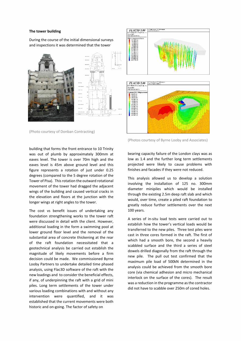
The elevations within the courtyard were fitted
with a grid of reflector prisms mounted on the
stone façade. Nine prisms were fixed to each wall
for a total of 45 prisms within the courtyard.
(Photo courtesy of Datum Monitoring)
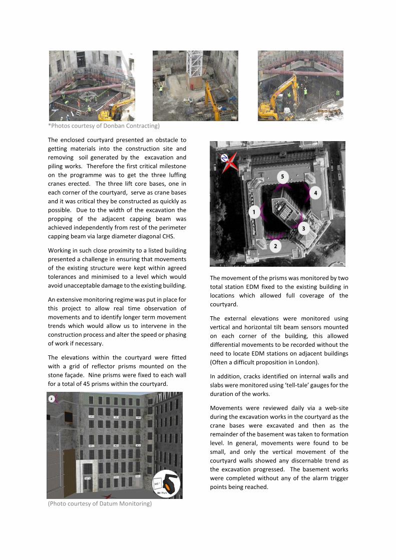
The movement of the prisms was monitored by two
total station EDM fixed to the existing building in
locations which allowed full coverage of the
courtyard.
The external elevations were monitored using
vertical and horizontal tilt beam sensors mounted
on each corner of the building, this allowed
differential movements to be recorded without the
need to locate EDM stations on adjacent buildings
(Often a difficult proposition in London).
In addition, cracks identified on internal walls and
slabs were monitored using ‘tell-tale’ gauges for the
duration of the works.
Movements were reviewed daily via a web-site
during the excavation works in the courtyard as the
crane bases were excavated and then as the
remainder of the basement was taken to formation
level. In general, movements were found to be
small, and only the vertical movement of the
courtyard walls showed any discernable trend as
the excavation progressed. The basement works
were completed without any of the alarm trigger
points being reached.
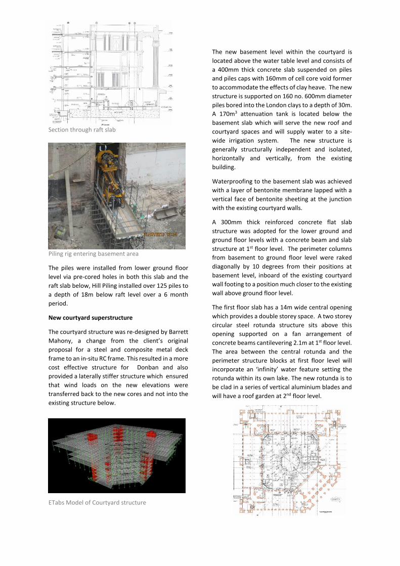
The tower building
During the course of the initial dimensional surveys
and inspections it was determined that the tower
(Photo courtesy of Donban Contracting)
building that forms the front entrance to 10 Trinity
was out of plumb by approximately 300mm at
eaves level. The tower is over 70m high and the
eaves level is 45m above ground level and this
figure represents a rotation of just under 0.25
degrees (compared to the 5 degree rotation of the
Tower of Pisa). This rotation the outward rotational
movement of the tower had dragged the adjacent
wings of the building and caused vertical cracks in
the elevation and floors at the junction with the
longer wings at right angles to the tower.
The cost vs benefit issues of undertaking any
foundation strengthening works to the tower raft
were discussed in detail with the client. However,
additional loading in the form a swimming pool at
lower ground floor level and the removal of the
substantial area of concrete thickening at the rear
of the raft foundation necessitated that a
geotechnical analysis be carried out establish the
magnitude of likely movements before a firm
decision could be made. We commissioned Byrne
Looby Partners to undertake detailed time phased
analysis, using Flac3D software of the raft with the
new loadings and to consider the beneficial effects,
if any, of underpinning the raft with a grid of mini
piles. Long term settlements of the tower under
various loading combinations with and without any
intervention were quantified, and it was
established that the current movements were both
historic and on-going. The factor of safety on
(Photos courtesy of Byrne Looby and Associates)
bearing capacity failure of the London clays was as
low as 1.4 and the further long term settlements
projected were likely to cause problems with
finishes and facades if they were not reduced.
This analysis allowed us to develop a solution
involving the installation of 125 no. 300mm
diameter minipiles which would be installed
through the existing 2.5m deep raft slab and which
would, over time, create a piled raft foundation to
greatly reduce further settlements over the next
100 years.
A series of in-situ load tests were carried out to
establish how the tower’s vertical loads would be
transferred to the new piles. Three test piles were
cast in three cores formed in the raft. The first of
which had a smooth bore, the second a heavily
scabbled surface and the third a series of steel
dowels drilled diagonally from the raft through the
new pile. The pull out test confirmed that the
maximum pile load of 500kN determined in the
analysis could be achieved from the smooth bore
core (via chemical adhesion and micro mechanical
interlock on the surface of the cores). The result
was a reduction in the programme as the contractor
did not have to scabble over 250m of cored holes.
Section through raft slab
Piling rig entering basement area
The piles were installed from lower ground floor
level via pre-cored holes in both this slab and the
raft slab below, Hill Piling installed over 125 piles to
a depth of 18m below raft level over a 6 month
period.
New courtyard superstructure
The courtyard structure was re-designed by Barrett
Mahony, a change from the client’s original
proposal for a steel and composite metal deck
frame to an in-situ RC frame. This resulted in a more
cost effective structure for Donban and also
provided a laterally stiffer structure which ensured
that wind loads on the new elevations were
transferred back to the new cores and not into the
existing structure below.
ETabs Model of Courtyard structure
The new basement level within the courtyard is
located above the water table level and consists of
a 400mm thick concrete slab suspended on piles
and piles caps with 160mm of cell core void former
to accommodate the effects of clay heave. The new
structure is supported on 160 no. 600mm diameter
piles bored into the London clays to a depth of 30m.
A 170m3 attenuation tank is located below the
basement slab which will serve the new roof and
courtyard spaces and will supply water to a site-
wide irrigation system. The new structure is
generally structurally independent and isolated,
horizontally and vertically, from the existing
building.
Waterproofing to the basement slab was achieved
with a layer of bentonite membrane lapped with a
vertical face of bentonite sheeting at the junction
with the existing courtyard walls.
A 300mm thick reinforced concrete flat slab
structure was adopted for the lower ground and
ground floor levels with a concrete beam and slab
structure at 1st floor level. The perimeter columns
from basement to ground floor level were raked
diagonally by 10 degrees from their positions at
basement level, inboard of the existing courtyard
wall footing to a position much closer to the existing
wall above ground floor level.
The first floor slab has a 14m wide central opening
which provides a double storey space. A two storey
circular steel rotunda structure sits above this
opening supported on a fan arrangement of
concrete beams cantilevering 2.1m at 1st floor level.
The area between the central rotunda and the
perimeter structure blocks at first floor level will
incorporate an ‘infinity’ water feature setting the
rotunda within its own lake. The new rotunda is to
be clad in a series of vertical aluminium blades and
will have a roof garden at 2nd floor level.
New central rotunda. (Photos courtesy of O’Keefe
Construction)
The floor plate at 2nd and 3rd floor level are limited
to a 6m wide bay around the perimeter of the
courtyard. The perimeter columns of this structure
provide support to the new 4th floor steel work
which spans over the existing building footprint.
The programme for construction was phased to
follow the production programme for the off-site
construction system to be adopted above 4th floor
level. It was important that these volumetric units
be placed as soon as they were completed and to
avoid the need for off-site storage. Thus the
construction of the perimeter elements of the
structure were given priority.
Lateral stability of the new courtyard structure is
provided by concrete stair cores in each corner of
the courtyard. These cores were also designed to
resist the lateral loads to the new structure above
4th floor level located over the existing building.
Thus the existing building only supports vertical
loads from the new floors at 4th and above. To
ensure that this is the case the floor plates of the
volumetric units at 4th floor and above are isolated
from the existing stair cores but are tied to the new
core structures located in the courtyard.
Seething Lane
Seething Lane Gardens is a public park, managed by
the City of London. Historically, diarist Samuel
Pepys lived and worked at the Navy Office, which
was originally situated on the present day Seething
Lane Gardens. The site was subsequently occupied
by warehousing, before becoming a public park.
A development of this size requires significant floor
area for back-of-house areas and car parking. In
order to maximise usable space within the existing
structure, it was decided to locate these outside the
footprint of the existing building. It was therefore
proposed to construct a new double storey
basement under Seething Lane Gardens, adjacent
to the existing structure. The basement is
approximately rectangular in shape, of maximum
internal width 21 m and maximum internal length
74 m. The original gardens were removed for the
duration of the excavation works and will be
reinstated as an improved public space on top of
the new basement.
The client’s original basement scheme featured a
secant pile wall. The pile line ran underneath the
public road and footpath, outside the boundary of
the gardens. Asset search information and site
surveys indicated a heavy concentration of services
under the road. It was estimated that it would take
up to a year to arrange diversions for these services,
at a potential cost of £1M. It was therefore decided
to move the outside edge of the structure within
the footprint of the existing gardens. The
implication of this was a reduction of floor space in
the proposed basement. In order to mitigate this,
BMCE proposed to redesign the structure as a steel-
intensive basement, featuring a sheet pile wall. This
would provide a gain of 500 mm around the
perimeter of the basement, and would compensate
for the loss in floor area. In coordination with the
design team, BMCE reconfigured the internal
structure to ensure that the original net floor area
could be accommodated within the reduced
footprint.
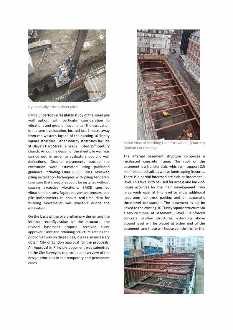
Hydraulically driven sheet piles
BMCE undertook a feasibility study of the sheet pile
wall option, with particular consideration to
vibrations and ground movements. The excavation
is in a sensitive location, located just 1 metre away
from the western façade of the existing 10 Trinity
Square structure. Other nearby structures include
St Olave’s Hart Street, a Grade I listed 15th century
church. An outline design of the sheet pile wall was
carried out, in order to evaluate sheet pile wall
deflections. Ground movements outside the
excavation were estimated using published
guidance, including CIRIA C580. BMCE reviewed
piling installation techniques with piling tenderers
to ensure that sheet piles could be installed without
causing excessive vibrations. BMCE specified
vibration monitors, façade movement sensors, and
pile inclinometers to ensure real-time data for
building movements was available during the
excavation.
On the basis of the pile preliminary design and the
internal reconfiguration of the structure, the
revised basement proposal received client
approval. Since the retaining structure retains the
public highway on three sides, it was also necessary
obtain City of London approval for the proposals.
An Approval in Principle document was submitted
to the City Surveyor, to provide an overview of the
design principles in the temporary and permanent
cases.
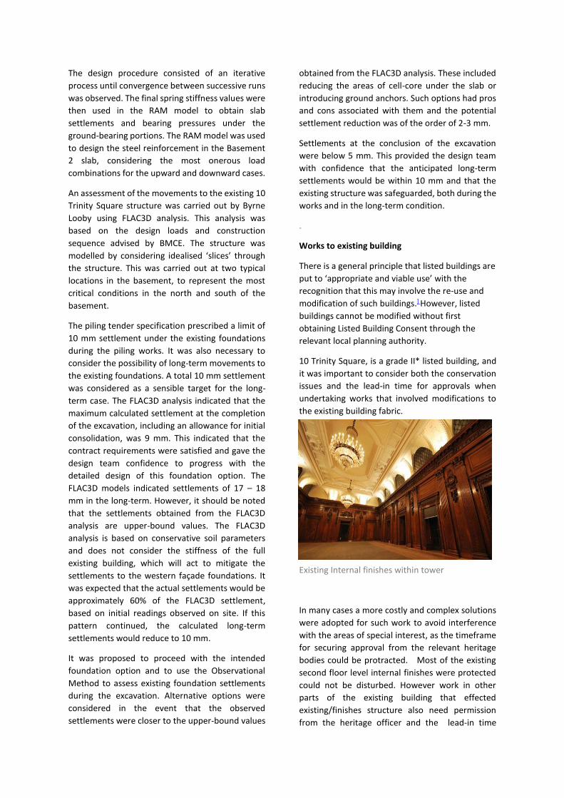
Aerial View of Seething Lane Excavation (Courtesy
Donban Contracting)
The internal basement structure comprises a
reinforced concrete frame. The roof of the
basement is a transfer slab, which will support 2.5
m of reinstated soil, as well as landscaping features.
There is a partial intermediate slab at Basement 1
level. This level is to be used for access and back-of-
house activities for the main development. Two
large voids exist at this level to allow additional
headroom for truck parking and an automatic
three-level car-stacker. The basement is to be
linked to the existing 10 Trinity Square structure via
a service tunnel at Basement 1 level. Reinforced
concrete pavilion structures, extending above
ground level will be placed at either end of the
basement, and these will house vehicle lifts for the

Welded sheet pile clutches and water bar plate
car-stacker and truck lift. The lowest basement
level is a raft slab comprising suspended slabs on
void-former spanning between ground bearing
strips. The internal walls and columns within the
basement are supported on the ground-bearing
slab strips and are subjected to permanent
downward loads from the structure and gardens
above. Void former is used to reduce the heave
pressures acting under the slab in the areas outside
of the ground-bearing strips.
Waterproofing to the sheet piling is achieved by welding the clutch joints between pile sections over their full internal height. A steel flange plate is welded the along the profile of the sheet pile wall at the junction between the slab and the sheet pile wall. At the interface with the lowest level slab, a bentonite seal is provided over the welded clutch as an additional protective measure. Waterproofing to the Basement 2 level slab is achieved with a proprietary tanking membrane, placed at the underside of the basement slab and ground beams. Particular consideration was given to the roof of the proposed basement, as this will be inaccessible following replanting of the Seething Lane Gardens. The roof slab will therefore be constructed with waterproof concrete, and a proprietary tanking membrane will be applied to the top of the slab.
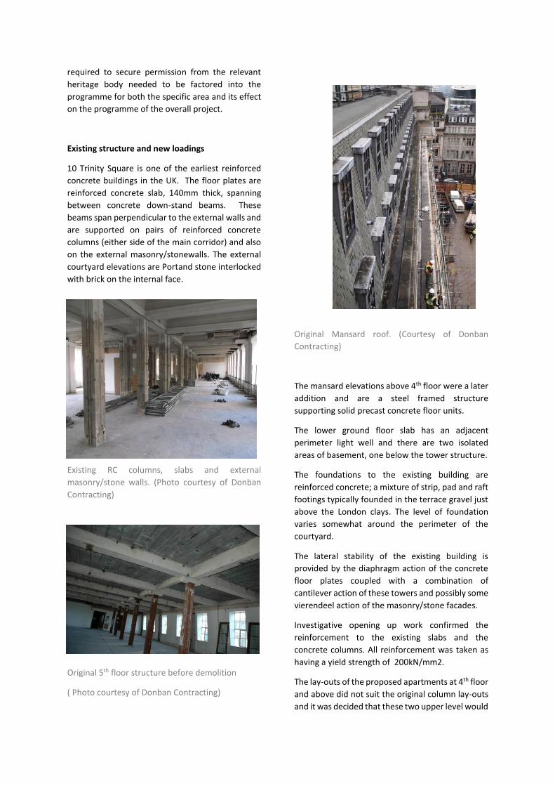
The excavation was generally 10.5 m deep and
involved the removal of 13500 m3 of material.
Given the historical importance of the site, the
excavation initially progressed to a depth of 5 m to
allow for a detailed archaeological excavation.
BMCE developed the initial temporary works
scheme, and the final design was carried out by the
groundworks contractor. In the temporary case, the
sheet pile wall spans between steel walers at two
levels which are propped across the full width of the
excavation. A third level of propping is provided at
the north end of the site, where a 13.5 m excavation
is required for the truck lift.
The original tender scheme had indicated a thick
basement slab on void-former. Tension piles were
provided to transfer vertical load and to resist both
hydrostatic and heave pressures. BMCE opted to
investigate alternatives on behalf of their client and
proposed a revised foundation scheme comprising
a 600 mm deep suspended slab on void-former
spanning between 1200 mm deep ground-bearing
strips. No ground anchors were used.
A key design issue was the ability of the structure to
resist uplift forces, and the consequent movement
to the existing building. As the formation level for
the Basement 2 slab is below the design water table
level, the structure is designed to resist hydrostatic
pressures. The ultimate stability of the structure for
the uplift case was assessed by comparing the
permanent downward forces against the
hydrostatic force. The structure is also designed to
resist heave pressure due to the swelling of the
unloaded clays. The long-term heave pressures
under the Basement 2 slab were advised by Byrne
Looby.
The basement structure was analysed using RAM
Concept software. The spring stiffness values for
this model were derived from a multi-stage pDisp
analysis carried out by Byrne Looby.
Extract from Flac3D Analysis for Basement
Excavation (Courtesy Byrne Looby Partners)
The design procedure consisted of an iterative
process until convergence between successive runs
was observed. The final spring stiffness values were
then used in the RAM model to obtain slab
settlements and bearing pressures under the
ground-bearing portions. The RAM model was used
to design the steel reinforcement in the Basement
2 slab, considering the most onerous load
combinations for the upward and downward cases.
An assessment of the movements to the existing 10
Trinity Square structure was carried out by Byrne
Looby using FLAC3D analysis. This analysis was
based on the design loads and construction
sequence advised by BMCE. The structure was
modelled by considering idealised ‘slices’ through
the structure. This was carried out at two typical
locations in the basement, to represent the most
critical conditions in the north and south of the
basement.
The piling tender specification prescribed a limit of
10 mm settlement under the existing foundations
during the piling works. It was also necessary to
consider the possibility of long-term movements to
the existing foundations. A total 10 mm settlement
was considered as a sensible target for the long-
term case. The FLAC3D analysis indicated that the
maximum calculated settlement at the completion
of the excavation, including an allowance for initial
consolidation, was 9 mm. This indicated that the
contract requirements were satisfied and gave the
design team confidence to progress with the
detailed design of this foundation option. The
FLAC3D models indicated settlements of 17 – 18
mm in the long-term. However, it should be noted
that the settlements obtained from the FLAC3D
analysis are upper-bound values. The FLAC3D
analysis is based on conservative soil parameters
and does not consider the stiffness of the full
existing building, which will act to mitigate the
settlements to the western façade foundations. It
was expected that the actual settlements would be
approximately 60% of the FLAC3D settlement,
based on initial readings observed on site. If this
pattern continued, the calculated long-term
settlements would reduce to 10 mm.
It was proposed to proceed with the intended
foundation option and to use the Observational
Method to assess existing foundation settlements
during the excavation. Alternative options were
considered in the event that the observed
settlements were closer to the upper-bound values
obtained from the FLAC3D analysis. These included
reducing the areas of cell-core under the slab or
introducing ground anchors. Such options had pros
and cons associated with them and the potential
settlement reduction was of the order of 2-3 mm.
Settlements at the conclusion of the excavation
were below 5 mm. This provided the design team
with confidence that the anticipated long-term
settlements would be within 10 mm and that the
existing structure was safeguarded, both during the
works and in the long-term condition.
.
Works to existing building
There is a general principle that listed buildings are
put to ‘appropriate and viable use’ with the
recognition that this may involve the re-use and
modification of such buildings.] However, listed
buildings cannot be modified without first
obtaining Listed Building Consent through the
relevant local planning authority.
10 Trinity Square, is a grade II* listed building, and
it was important to consider both the conservation
issues and the lead-in time for approvals when
undertaking works that involved modifications to
the existing building fabric.
Existing Internal finishes within tower
In many cases a more costly and complex solutions
were adopted for such work to avoid interference
with the areas of special interest, as the timeframe
for securing approval from the relevant heritage
bodies could be protracted. Most of the existing
second floor level internal finishes were protected
could not be disturbed. However work in other
parts of the existing building that effected
existing/finishes structure also need permission
from the heritage officer and the lead-in time
required to secure permission from the relevant
heritage body needed to be factored into the
programme for both the specific area and its effect
on the programme of the overall project.
Existing structure and new loadings
10 Trinity Square is one of the earliest reinforced
concrete buildings in the UK. The floor plates are
reinforced concrete slab, 140mm thick, spanning
between concrete down-stand beams. These
beams span perpendicular to the external walls and
are supported on pairs of reinforced concrete
columns (either side of the main corridor) and also
on the external masonry/stonewalls. The external
courtyard elevations are Portand stone interlocked
with brick on the internal face.
Existing RC columns, slabs and external
masonry/stone walls. (Photo courtesy of Donban
Contracting)
Original 5th floor structure before demolition
( Photo courtesy of Donban Contracting)
Original Mansard roof. (Courtesy of Donban
Contracting)
The mansard elevations above 4th floor were a later
addition and are a steel framed structure
supporting solid precast concrete floor units.
The lower ground floor slab has an adjacent
perimeter light well and there are two isolated
areas of basement, one below the tower structure.
The foundations to the existing building are
reinforced concrete; a mixture of strip, pad and raft
footings typically founded in the terrace gravel just
above the London clays. The level of foundation
varies somewhat around the perimeter of the
courtyard.
The lateral stability of the existing building is
provided by the diaphragm action of the concrete
floor plates coupled with a combination of
cantilever action of these towers and possibly some
vierendeel action of the masonry/stone facades.
Investigative opening up work confirmed the
reinforcement to the existing slabs and the
concrete columns. All reinforcement was taken as
having a yield strength of 200kN/mm2.
The lay-outs of the proposed apartments at 4th floor
and above did not suit the original column lay-outs
and it was decided that these two upper level would
be removed and replaced with a new structure
better suited to accommodate the proposed
layouts. The client’s original scheme adopted a
conventional steel framed structure for these
additional floors. The support of this structure
involved partial demolition of the existing fourth
floor plate and strengthening of the existing
concrete beams at this level and below. Donban, in
conjunction with Barrett Mahony proposed the use
of volumetric construction, a state-of-the-art off-
site construction system , rather than a steel frame,
for these additional stories. This had a number of
advantages including a reduction in the
construction programme but the chief advantage
lay in the fact that the walls of the units would act
as the new vertical load bearing structure and
remove the need for individual columns that would
compromise the internal lay-out of these high end
apartments. The use of these off-site elements is
described later in this paper.
The demolition of the existing roof, 5th and 4th floor
slabs was carried out in tandem with piling works
within the courtyard. Non percussive techniques
were used as far as possible to minimise the risk of
(Photo courtesy of Donban Contracting)
Demolition of 4th floor slab
damage to protected finishes down at level 2.
Barrett Mahony were responsible for designing the
temporary works for propping the existing floors
and providing temporary stability to the existing
structure while the demolition was carried out. It
was necessary to create a temporary roof at 3rd
floor level to weather the building below until the
new floor plates where added at 4th floor level.
The addition of the new above 4th floor resulted in
increases in vertical load in both the external
masonry and the internal concrete columns and a
detailed assessment was required to determine
how the existing structure would handle these
loads.
Material testing
As with any historic building an intensive desktop
study was carried to source existing drawings.
Given that the building was constructed in the
1920’s this proved difficult and very little
information was available. Masonry and concrete
cores were taken and tested to determine average
and lower bound strengths and the condition of the
in-situ materials.
The masonry test samples yielded compressive
strengths of 20.9-44.9N/mm2 with an average
strength of 33N/mm2. It was found that the lower
bound strength was adequate for capacity checks
on new load to existing piers in all cases.
The original investigation had taken 28 core
samples from columns around the original building
at different levels and the compressive strengths of
the in-situ concrete ranged from 14.6-34.3 N/mm2
with an average strength of 22.1N/mm2. The initial
loading calculations and the analysis of the existing
columns with the new loadings applied from the
additional storeys above showed that typically that
the lowest tested strength of 14.6N/mm2 was
sufficient for the new loadings.
However, there were local areas where increased
floor spans meant that the new loads would be too
high for existing column capacities based on this
lower bound strength. A back analysis also
determined that if his lowest strength was assumed
to apply in these area the existing columns could
not be justified for the original loads as suggested
by the 1920’s London Building Acts. (an imposed
load of 4.8kN/m2 was suggested for office
buildings). We decided that it was necessary to
carry out further core tests on columns in each wing
and at each level to get a better representation of
the available compressive strength in these specific
areas. A further 22 no. core tests were taken with
an average strength of 30.2N/mm2 and based on a
statistical analysis of the data both globally and on
a quadrant by quadrant basis using BS EN 1379
1nad BS 6089 it was determined that no column
strengthening was required to resist the new
loadings. This was a similar situation for the floor
slab and beams where the new loads did not
present a problem for the existing structure.
The effect of differential settlements between
existing foundations also needed to be considered.
Within the existing structure the new transfer steel
grillage at 4th floor did not load all of the existing
columns by exactly the same amount. An analysis
was carried out on a number of adjacent internal
columns and external masonry piers where there
was greater than 10% difference in total service
load and it was determined that the differential
settlement/heave movements were acceptable,
being in the order of L/1000 or better between
adjacent footings. The expected long term
differential movements between the tower raft
slab (now plied raft slab) and the adjacent corridor
strip flooring was also checked and determined not
to pose a problem.
A similar exercise was carried out between the
tower structure and the adjacent courtyard
structure that was partially supported on the out
stand at the rear of the tower raft. The new
courtyard structure was designed to resist the
forces generated by the differential settlements
between the columns on the raft and those on the
courtyard piles.
Robustness and stability
The addition of additional storeys and a material
change of use for the building required us to
consider the issue of disproportionate collapse in
the existing building.
The capacity of the existing slabs were checked to resist notional horizontal tie forces in both directions. In the direction of the span there was adequate existing reinforcement to resist the required tie forces and also to provide the necessary peripheral tie.
In the opposite direction, perpendicular to the span, the beams have been used as ties and it was shown that they were adequately reinforced to resist the prescribed tie force with respect to the floor area they support.
The existing columns and external masonry walls were checked as protected elements. The masonry piers with the lowest vertical loads were selected and checked at a number of levels for an explosive pressure of 34kN/m2. The external masonry walls on the external elevations satisfied this requirement by three-pin arching action between the existing concrete floor plates. The masonry stair core walls were checked by the same method and deemed to be adequate.
Remedial work to existing building
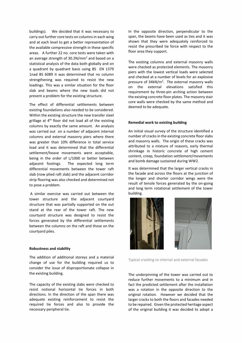
An initial visual survey of the structure identified a number of cracks in the existing concrete floor slabs and masonry walls. The origin of these cracks was attributed to a mixture of reasons, early thermal shrinkage in historic concrete of high cement content, creep, foundation settlement/movements and bomb damage sustained during WW2.
It was determined that the larger vertical cracks in the facade and across the floors at the junction of the longer and shorter corridor wings were the result of tensile forces generated by the on-going and long term rotational settlement of the tower building.
Typical cracking to internal and external facades
The underpinning of the tower was carried out to reduce further movements to a minimum and in fact the predicted settlement after the installation was a rotation in the opposite direction to the original rotation. However we decided that the larger cracks to both the floors and facades needed to be repaired. Given the protected heritage aspect of the original building it was decided to adopt a
minimalist approach to these repairs, limiting intervention in the original building fabric where possible. It was envisaged instead that the design and installation of new internal finishes within the existing building would have to take cognizance of the fact that this is an historic structure and that allowable movement tolerances would need to be greater that those associated with a new structure, particularly at the junction between the corridor wings and the existing stair cores.
The remedial works to the cracks in these areas would provide restraints only to on on-going thermal movements as the main action on the existing cracks. The other movement drivers having either already stopped eg shrinkage, or have been dealt with by alternative means eg underpinning of the tower raft.
The proposals was to repair the larger cracks in floor slabs were with cementious mortar and small diameter reinforcement bars laid at close centers in saw cut slots on the top of the slab across each crack.
The larger cracks in the external walls where tied with stainless steel rods either drilled longitudinally thru the wall at window reveals (Helifix ChemTies) or placed in saw-cut slots in the inner face of the wall (Helifix Helibars). We decided that any saw cutting of the external stone to install ties would likely cause more damage in the long term, thus cracks in the Portland stone were to be repaired with a colour matched grout. The programme for this work was pushed as close to the completion date of internal finishes as possible to allow any construction induced settlements to have occurred.
Fourth floor structure and the upper levels.
The client’s original proposal for the additional
upper four floors was a traditional design of
structural steel with composite metal deck slabs.
The scheme involved partial demolition of the
original 4th floor structure along with strengthening
of the existing 4th concrete floor beams to provide
support to the new structure above. In addition,
some internal diagonal columns were utilised to
achieve continuity within the structure and transfer
additional loads away from the existing structure
and back to the new build elements. This scheme
had a number of columns located in positions that
necessitated a compromise in the desired
architectural lay-outs.
In conjunction with the contractor we proposed an
alternative solution that would adopt a state-of-the
art off-site construction system for these upper
floors with the advantage of a reduced programme
and a better defined load path both vertically and
horizontally. And most importantly, the walls of the
units would be load bearing and would remove the
need for a traditional grid of columns structural
columns that might compromise apartment lay-
outs.
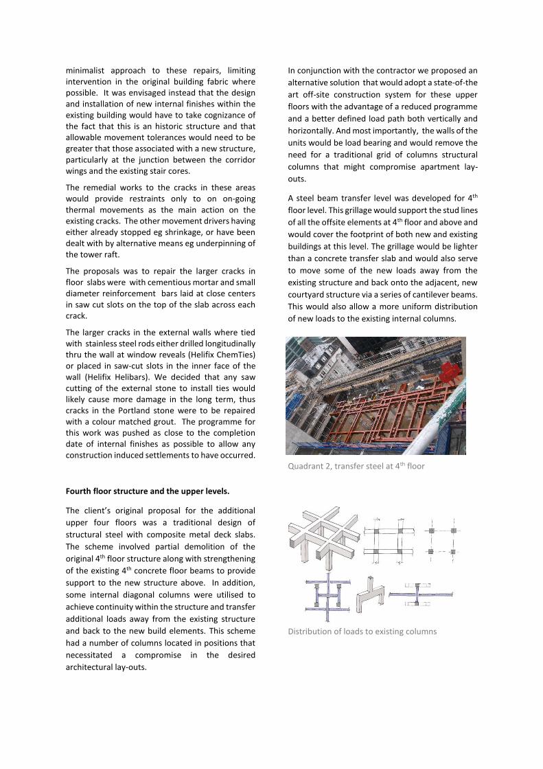
A steel beam transfer level was developed for 4th
floor level. This grillage would support the stud lines
of all the offsite elements at 4th floor and above and
would cover the footprint of both new and existing
buildings at this level. The grillage would be lighter
than a concrete transfer slab and would also serve
to move some of the new loads away from the
existing structure and back onto the adjacent, new
courtyard structure via a series of cantilever beams.
This would also allow a more uniform distribution
of new loads to the existing internal columns.
Quadrant 2, transfer steel at 4th floor
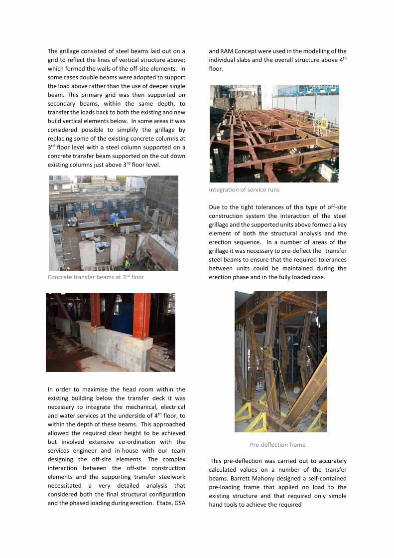
Distribution of loads to existing columns
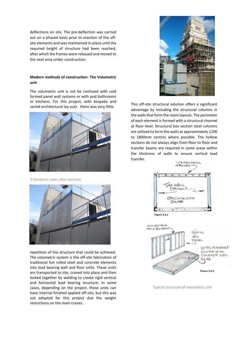
The grillage consisted of steel beams laid out on a
grid to reflect the lines of vertical structure above;
which formed the walls of the off-site elements. In
some cases double beams were adopted to support
the load above rather than the use of deeper single
beam. This primary grid was then supported on
secondary beams, within the same depth, to
transfer the loads back to both the existing and new
build vertical elements below. In some areas it was
considered possible to simplify the grillage by
replacing some of the existing concrete columns at
3rd floor level with a steel column supported on a
concrete transfer beam supported on the cut down
existing columns just above 3rd floor level.
Concrete transfer beams at 3rd floor
In order to maximise the head room within the
existing building below the transfer deck it was
necessary to integrate the mechanical, electrical
and water services at the underside of 4th floor, to
within the depth of these beams. This approached
allowed the required clear height to be achieved
but involved extensive co-ordination with the
services engineer and in-house with our team
designing the off-site elements. The complex
interaction between the off-site construction
elements and the supporting transfer steelwork
necessitated a very detailed analysis that
considered both the final structural configuration
and the phased loading during erection. Etabs, GSA
and RAM Concept were used in the modelling of the
individual slabs and the overall structure above 4th
floor.
Integration of service runs
Due to the tight tolerances of this type of off-site
construction system the interaction of the steel
grillage and the supported units above formed a key
element of both the structural analysis and the
erection sequence. In a number of areas of the
grillage it was necessary to pre-deflect the transfer
steel beams to ensure that the required tolerances
between units could be maintained during the
erection phase and in the fully loaded case.
Pre-deflection frame
This pre-deflection was carried out to accurately
calculated values on a number of the transfer
beams. Barrett Mahony designed a self-contained
pre-loading frame that applied no load to the
existing structure and that required only simple
hand tools to achieve the required
deflections on site. The pre-deflection was carried
out on a phased basis prior to erection of the off-
site elements and was maintained in-place until the
required height of structure had been reached,
after which the frames were released and moved to
the next area under construction.
Modern methods of construction- The Volumetric
unit
The volumetric unit is not be confused with cold formed panel wall systems or with pod bathrooms or kitchens. For this project, with bespoke and varied architectural lay-outs there was very little
Volumetric units after erection
repetition of the structure that could be achieved. The volumetric system is the off-site fabrication of traditional hot rolled steel and concrete elements into load bearing wall and floor units. These units are transported to site, craned into place and then locked together by welding to create rigid vertical and horizontal load bearing structure. In some cases, depending on the project, these units can have internal finished applied off-site, but this was not adopted for this project due the weight restrictions on the main cranes.
This off-site structural solution offers a significant
advantage by including the structural columns in
the walls that form the room layouts. The perimeter
of each element is formed with a structural channel
at floor level. Structural box section steel columns
are utilised to form the walls at approximately 1200
to 1800mm centres where possible. The hollow
sections do not always align from floor to floor and
transfer beams are required in some areas within
the thickness of walls to ensure vertical load
transfer.
Typical structure of volumetric unit
Figure 3.4.3
Figure 3.4.1
The ceiling is constructed with 150mm deep trusses
which facilitate services, ceiling support and site
access. These trusses also tie the opposing walls
together and offer robustness to the construction.
The floor of each unit is constructed with
lightweight concrete to reduce the weight on the
transfer structures below. The off-site units extend
to include corridors and so provide full coverage of
each floor outside of the traditional build areas.
Each off-site unit that is erected has an
independent floor slab. These slabs are connected
together on site in various locations, some of which
provide for diaphragm action to take horizontal
loads, and some to ensure that adjacent units act
together for vertical displacements both on short
and long term. The lateral stability of such a
structural system is different from a traditional
concrete structure where the floor diaphragm is
deemed to be homogenous and able to transfer the
in-plane load almost without further analysis. In this
case a detailed analysis is needed to examine the
discrete connection forces between the individual
floor units and how these loads are transferred to
the vertical braced elements, in this case the
stair/lift cores. The connections between the units
provide the necessary strut and tie forces to
minimise differential displacements between the
various parts of the diaphragm and ensure
predictable interaction between the connection
plates and the individual floor slabs. The
connections are also checked for the accidental
damage load cases, robustness and
disproportionate collapse.
The floor slabs are connected to the new concrete
stair/lift cores which are designed to provide the
building stability. There is no physical connection
between the new floor plates and the masonry stair
cores of the existing building. Thus all additional
lateral loads and are resisted exclusively by the new
concrete stair/lift cores in the courtyard.
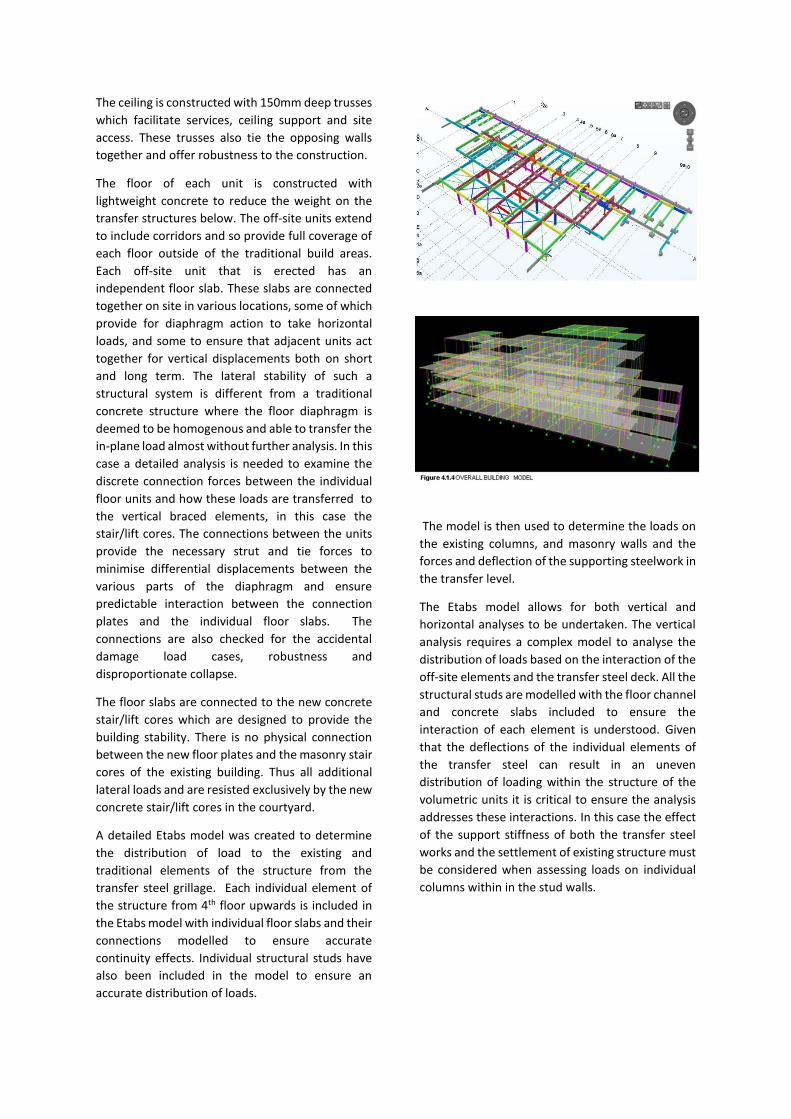
A detailed Etabs model was created to determine
the distribution of load to the existing and
traditional elements of the structure from the
transfer steel grillage. Each individual element of
the structure from 4th floor upwards is included in
the Etabs model with individual floor slabs and their
connections modelled to ensure accurate
continuity effects. Individual structural studs have
also been included in the model to ensure an
accurate distribution of loads.
The model is then used to determine the loads on
the existing columns, and masonry walls and the
forces and deflection of the supporting steelwork in
the transfer level.
The Etabs model allows for both vertical and
horizontal analyses to be undertaken. The vertical
analysis requires a complex model to analyse the
distribution of loads based on the interaction of the
off-site elements and the transfer steel deck. All the
structural studs are modelled with the floor channel
and concrete slabs included to ensure the
interaction of each element is understood. Given
that the deflections of the individual elements of
the transfer steel can result in an uneven
distribution of loading within the structure of the
volumetric units it is critical to ensure the analysis
addresses these interactions. In this case the effect
of the support stiffness of both the transfer steel
works and the settlement of existing structure must
be considered when assessing loads on individual
columns within in the stud walls.
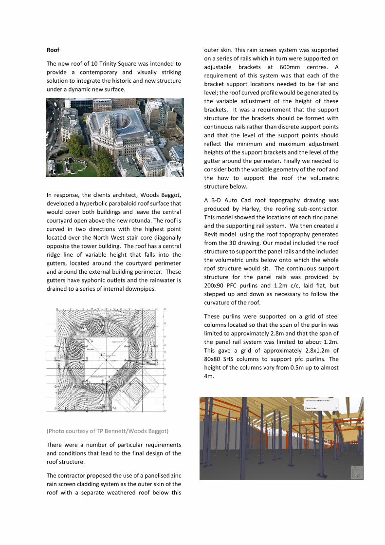
Roof
The new roof of 10 Trinity Square was intended to
provide a contemporary and visually striking
solution to integrate the historic and new structure
under a dynamic new surface.
In response, the clients architect, Woods Baggot,
developed a hyperbolic parabaloid roof surface that
would cover both buildings and leave the central
courtyard open above the new rotunda. The roof is
curved in two directions with the highest point
located over the North West stair core diagonally
opposite the tower building. The roof has a central
ridge line of variable height that falls into the
gutters, located around the courtyard perimeter
and around the external building perimeter. These
gutters have syphonic outlets and the rainwater is
drained to a series of internal downpipes.
(Photo courtesy of TP Bennett/Woods Baggot)
There were a number of particular requirements
and conditions that lead to the final design of the
roof structure.
The contractor proposed the use of a panelised zinc
rain screen cladding system as the outer skin of the
roof with a separate weathered roof below this
outer skin. This rain screen system was supported
on a series of rails which in turn were supported on
adjustable brackets at 600mm centres. A
requirement of this system was that each of the
bracket support locations needed to be flat and
level; the roof curved profile would be generated by
the variable adjustment of the height of these
brackets. It was a requirement that the support
structure for the brackets should be formed with
continuous rails rather than discrete support points
and that the level of the support points should
reflect the minimum and maximum adjustment
heights of the support brackets and the level of the
gutter around the perimeter. Finally we needed to
consider both the variable geometry of the roof and
the how to support the roof the volumetric
structure below.
A 3-D Auto Cad roof topography drawing was
produced by Harley, the roofing sub-contractor.
This model showed the locations of each zinc panel
and the supporting rail system. We then created a
Revit model using the roof topography generated
from the 3D drawing. Our model included the roof
structure to support the panel rails and the included
the volumetric units below onto which the whole
roof structure would sit. The continuous support
structure for the panel rails was provided by
200x90 PFC purlins and 1.2m c/c, laid flat, but
stepped up and down as necessary to follow the
curvature of the roof.
These purlins were supported on a grid of steel
columns located so that the span of the purlin was
limited to approximately 2.8m and that the span of
the panel rail system was limited to about 1.2m.
This gave a grid of approximately 2.8x1.2m of
80x80 SHS columns to support pfc purlins. The
height of the columns vary from 0.5m up to almost
4m.
The purlins are set-out to run parallel to the roof
contours as far as possible to help minimise the
number of locations where the purlins would need
to step in level around the roof plan.
Even with this approach there where many changes
in level required. The SHS columns will be site fixed
to the roof of modules below.
Roof support posts wind bracing is highlighted in
RED
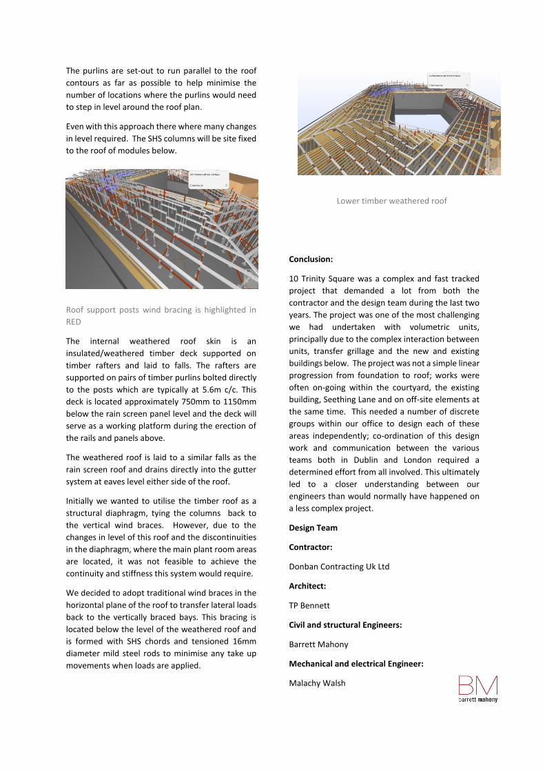
The internal weathered roof skin is an
insulated/weathered timber deck supported on
timber rafters and laid to falls. The rafters are
supported on pairs of timber purlins bolted directly
to the posts which are typically at 5.6m c/c. This
deck is located approximately 750mm to 1150mm
below the rain screen panel level and the deck will
serve as a working platform during the erection of
the rails and panels above.
The weathered roof is laid to a similar falls as the
rain screen roof and drains directly into the gutter
system at eaves level either side of the roof.
Initially we wanted to utilise the timber roof as a
structural diaphragm, tying the columns back to
the vertical wind braces. However, due to the
changes in level of this roof and the discontinuities
in the diaphragm, where the main plant room areas
are located, it was not feasible to achieve the
continuity and stiffness this system would require.
We decided to adopt traditional wind braces in the
horizontal plane of the roof to transfer lateral loads
back to the vertically braced bays. This bracing is
located below the level of the weathered roof and
is formed with SHS chords and tensioned 16mm
diameter mild steel rods to minimise any take up
movements when loads are applied.
Lower timber weathered roof
Conclusion:
10 Trinity Square was a complex and fast tracked
project that demanded a lot from both the
contractor and the design team during the last two
years. The project was one of the most challenging
we had undertaken with volumetric units,
principally due to the complex interaction between
units, transfer grillage and the new and existing
buildings below. The project was not a simple linear
progression from foundation to roof; works were
often on-going within the courtyard, the existing
building, Seething Lane and on off-site elements at
the same time. This needed a number of discrete
groups within our office to design each of these
areas independently; co-ordination of this design
work and communication between the various
teams both in Dublin and London required a
determined effort from all involved. This ultimately
led to a closer understanding between our
engineers than would normally have happened on
a less complex project.
Design Team
Contractor:
Donban Contracting Uk Ltd
Architect:
TP Bennett
Civil and structural Engineers:
Barrett Mahony
Mechanical and electrical Engineer:
Malachy Walsh