JAKE'S CHAIR, AMENDED Based on an article by …S CHAIR, AMENDED Based on an article by Tom...
13
a Jakes Chair, by Tom Gauldin, as revised April 08, 1998. The plans, photographs and text file for Gauldin’s version of Jake's chair and footstool are available for free in .ZIP format from many sites on the internet (just search for Jakes chair), including http://www.jakeschair.com/download.php. Gauldin’s original description was written to walk a novice woodworker through the process of building the chair. In addition to design modifications, for my own convenience, I edited out considerable amounts of original text, paraphrased some, refined the estimate of wood required, and added some detail to the rough cut list. Gauldin is not responsible for any errors and omissions that I might introduce in my version. 1 JAKE'S CHAIR, AMENDED Based on an article by Tom Gauldin a . C.D. Hepler July, 2009 Introduction Jake's Chair is similar to an Adirondack chair, but the back is curved and the seat is contoured. Tom Gauldin, who designed the original version of this chair, wrote that he called it "Jake's Chair" in honor of Judge Jake Robertson, of Marshall, MO, who first designed it for his front porch. Gauldin’s a design is stable and reasonably easy to build. It includes level arms at a good height for holding a book. The chair arms extend forward to assist in rising from the chair and are wide enough to easily hold a glass or dish. I have modified the design somewhat. I made the back longer, to support the head of a tall person. The longer back requires a back stretcher near the top of the back. The upper back support (UBS) is attached to the arms rather than the arm runners. (See Figure 2.) This addressees a weakness that Gauldin recognized in his design, that the upper back support could sometimes split. The original design screwed the upper back support to the arm runners. Attaching it to the arms makes a stronger joint because long grain is glued to long grain. Figure 1. Jake’s Chairs, Amended, and 27" Footstools, Varnished Cypress Figure 2. Side Detail of Jakes Chair Amended
Transcript of JAKE'S CHAIR, AMENDED Based on an article by …S CHAIR, AMENDED Based on an article by Tom...
a Jakes Chair, by Tom Gauldin, as revised April 08, 1998. The plans, photographs and text file forGauldin’s version of Jake's chair and footstool are available for free in .ZIP format from many sites on the internet(just search for Jakes chair), including http://www.jakeschair.com/download.php. Gauldin’s original description waswritten to walk a novice woodworker through the process of building the chair. In addition to design modifications,for my own convenience, I edited out considerable amounts of original text, paraphrased some, refined the estimateof wood required, and added some detail to the rough cut list. Gauldin is not responsible for any errors andomissions that I might introduce in my version.
1
JAKE'S CHAIR, AMENDEDBased on an article by Tom Gauldina. C.D. HeplerJuly, 2009
Introduction
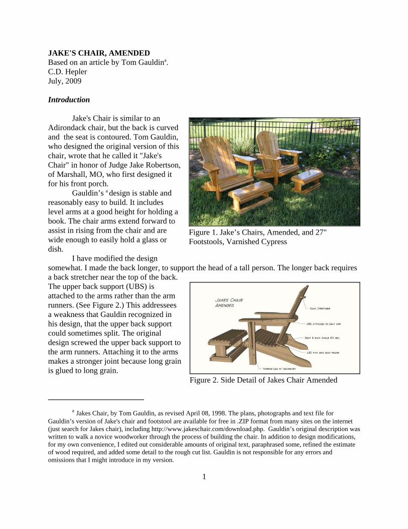
Jake's Chair is similar to anAdirondack chair, but the back is curvedand the seat is contoured. Tom Gauldin,who designed the original version of thischair, wrote that he called it "Jake'sChair" in honor of Judge Jake Robertson,of Marshall, MO, who first designed itfor his front porch.
Gauldin’s a design is stable andreasonably easy to build. It includeslevel arms at a good height for holding abook. The chair arms extend forward toassist in rising from the chair and arewide enough to easily hold a glass ordish.
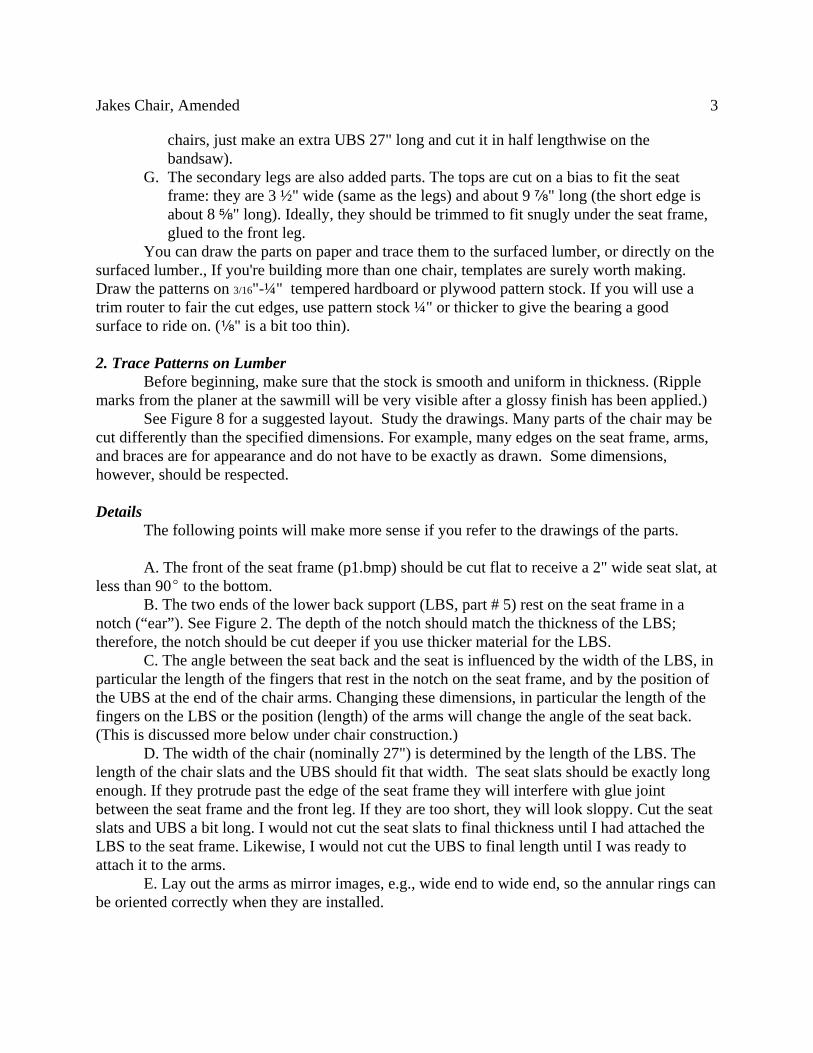
I have modified the designsomewhat. I made the back longer, to support the head of a tall person. The longer back requiresa back stretcher near the top of the back.The upper back support (UBS) isattached to the arms rather than the armrunners. (See Figure 2.) This addresseesa weakness that Gauldin recognized inhis design, that the upper back supportcould sometimes split. The originaldesign screwed the upper back support tothe arm runners. Attaching it to the armsmakes a stronger joint because long grainis glued to long grain.
Figure 1. Jake’s Chairs, Amended, and 27"Footstools, Varnished Cypress
Figure 2. Side Detail of Jakes Chair Amended

Jakes Chair, Amended 2
b Try http://www.xmission.com/~sherwin/download1.htm
I also increased the angle of the back to the seat, or at least I revised the constructiondetails so that the angle would be more reproducible. It was possible for me to follow theoriginal directions carefully, and still produce a chair with a seat angle of less than 90E An angleof 90E is the minimum comfortable angle, and would be a bit too narrow for most people,especially if they use the footstool. An angle of about 100E provides lumbar support and makesthe chair more comfortable for a larger person, although it might require a pillow behind thehead.
Finally, I thought that the front leg looked disproportionately wide, and I did not expectthat ¾" cedar or cypress would withstand lateral stress and being dragged across a floor. Inarrowed the width of the front legs and added a secondary leg as a seat frame support to theinside of the front leg. This yields a narrower, stronger front leg structure.
This is a large chair. As modified it requires about 36 x 38" of floor space, plus thefootstool. It is comfortable without cushions.
1. Plans With a few exceptions, noted below, the parts for the amended chair are identical to the
parts for the original chair. Download and print out each of Gauldin’s .bmp drawings of the parts(P1.bmp - P12.bmp. Almost any graphics display program should handle the bmp format.) Theywill print out on 8 ½ x 11" paper. Also, CAD drawings, prepared by Scott Brownell, areavailable on the web.b
Prepare full-size drawings. You can draw them easily enough, or you can printBrownell’s CAD drawings to full scale. Theoretically, you can enlarge the BMP drawings, butin reality is is much quicker to draw them than to get each one to accurate full scale. (Each bmpdrawing has a different scale.)
The following parts are different in my amended version: A. The seat frame is 7-7¼" wide, so it can be cut from a nominal 8" wide 5/4 board. The
original dimensions of the seat frame (aka lounging leg) called for 8" actual width of¾ thick stock. I think a 7" wide seat frame is plenty strong enough in 1" thick cypress(5/4" stock) if the stock is dense and sound. Or, you could buy a 5/4 x 10 for this part.You will also use 5/4 stock to make the front legs (See Fig 7, Layout).
B. The legs are about 3½" wide (cut two from a nominal 8" board). They require 5/4stock.
C. The chair arms (See Figure 7.) should be about 29" long (2" longer than in theoriginal design shown in p2.bmp). Add the length to the wide part. If you want tomake them shorter, you can move them back, leaving less overhang in front of thelegs.
D. The seat back blanks are 35" long.E. The upper back support (aka upper back brace – part #4) should be cut to 32" (rough)
and trimmed to fit during assembly time.F. The back stretcher is an additional part. It can be made from the pattern for the upper
back support (part # 4), 27" long and about half as wide. (If you are making two
Jakes Chair, Amended 3
chairs, just make an extra UBS 27" long and cut it in half lengthwise on thebandsaw).
G. The secondary legs are also added parts. The tops are cut on a bias to fit the seatframe: they are 3 ½" wide (same as the legs) and about 9 f" long (the short edge isabout 8 e" long). Ideally, they should be trimmed to fit snugly under the seat frame,glued to the front leg.
You can draw the parts on paper and trace them to the surfaced lumber, or directly on thesurfaced lumber., If you're building more than one chair, templates are surely worth making.Draw the patterns on 3/16"-¼" tempered hardboard or plywood pattern stock. If you will use atrim router to fair the cut edges, use pattern stock ¼" or thicker to give the bearing a goodsurface to ride on. (c" is a bit too thin).
2. Trace Patterns on LumberBefore beginning, make sure that the stock is smooth and uniform in thickness. (Ripple
marks from the planer at the sawmill will be very visible after a glossy finish has been applied.)See Figure 8 for a suggested layout. Study the drawings. Many parts of the chair may be
cut differently than the specified dimensions. For example, many edges on the seat frame, arms,and braces are for appearance and do not have to be exactly as drawn. Some dimensions,however, should be respected.
DetailsThe following points will make more sense if you refer to the drawings of the parts.
A. The front of the seat frame (p1.bmp) should be cut flat to receive a 2" wide seat slat, atless than 90E to the bottom.
B. The two ends of the lower back support (LBS, part # 5) rest on the seat frame in anotch (“ear”). See Figure 2. The depth of the notch should match the thickness of the LBS;therefore, the notch should be cut deeper if you use thicker material for the LBS.
C. The angle between the seat back and the seat is influenced by the width of the LBS, inparticular the length of the fingers that rest in the notch on the seat frame, and by the position ofthe UBS at the end of the chair arms. Changing these dimensions, in particular the length of thefingers on the LBS or the position (length) of the arms will change the angle of the seat back.(This is discussed more below under chair construction.)
D. The width of the chair (nominally 27") is determined by the length of the LBS. Thelength of the chair slats and the UBS should fit that width. The seat slats should be exactly longenough. If they protrude past the edge of the seat frame they will interfere with glue jointbetween the seat frame and the front leg. If they are too short, they will look sloppy. Cut the seatslats and UBS a bit long. I would not cut the seat slats to final thickness until I had attached theLBS to the seat frame. Likewise, I would not cut the UBS to final length until I was ready toattach it to the arms.
E. Lay out the arms as mirror images, e.g., wide end to wide end, so the annular rings canbe oriented correctly when they are installed.
Jakes Chair, Amended 4
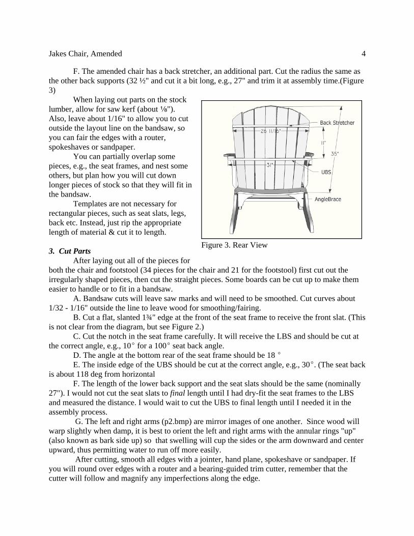
F. The amended chair has a back stretcher, an additional part. Cut the radius the same asthe other back supports (32 ½" and cut it a bit long, e.g., 27" and trim it at assembly time.(Figure3)
When laying out parts on the stocklumber, allow for saw kerf (about c").Also, leave about 1/16" to allow you to cutoutside the layout line on the bandsaw, soyou can fair the edges with a router,spokeshaves or sandpaper.
You can partially overlap somepieces, e.g., the seat frames, and nest someothers, but plan how you will cut downlonger pieces of stock so that they will fit inthe bandsaw.
Templates are not necessary forrectangular pieces, such as seat slats, legs,back etc. Instead, just rip the appropriatelength of material & cut it to length.
3. Cut Parts After laying out all of the pieces for
both the chair and footstool (34 pieces for the chair and 21 for the footstool) first cut out theirregularly shaped pieces, then cut the straight pieces. Some boards can be cut up to make themeasier to handle or to fit in a bandsaw.
A. Bandsaw cuts will leave saw marks and will need to be smoothed. Cut curves about1/32 - 1/16" outside the line to leave wood for smoothing/fairing.
B. Cut a flat, slanted 1¾" edge at the front of the seat frame to receive the front slat. (Thisis not clear from the diagram, but see Figure 2.)
C. Cut the notch in the seat frame carefully. It will receive the LBS and should be cut atthe correct angle, e.g., 10E for a 100E seat back angle.
D. The angle at the bottom rear of the seat frame should be 18 E E. The inside edge of the UBS should be cut at the correct angle, e.g., 30E. (The seat back
is about 118 deg from horizontal F. The length of the lower back support and the seat slats should be the same (nominally
27"). I would not cut the seat slats to final length until I had dry-fit the seat frames to the LBSand measured the distance. I would wait to cut the UBS to final length until I needed it in theassembly process.
G. The left and right arms (p2.bmp) are mirror images of one another. Since wood willwarp slightly when damp, it is best to orient the left and right arms with the annular rings "up"(also known as bark side up) so that swelling will cup the sides or the arm downward and center upward, thus permitting water to run off more easily.
After cutting, smooth all edges with a jointer, hand plane, spokeshave or sandpaper. Ifyou will round over edges with a router and a bearing-guided trim cutter, remember that thecutter will follow and magnify any imperfections along the edge.
Figure 3. Rear View

Jakes Chair, Amended 5
Layout of Back The back comprises seven boards. The boards are cut square on the bottom, but the tops
are cut so that when assembled, they form an arc.A. Cut seven boards for the back to a width of 3-1/4" and a uniform length of 35". (The
original plan called for 31".) B. Place the boards together, face down, on a flat surface. The corners of the bottoms of
the back slats should touch. The top pieces should be flared to a width of 28¾".The gap between the tops of all seven boards should be uniform (a bit less than 1").
Mark the center of the center slat 17 ¼" from the top. Draw a 17" radius from this pointacross the top of the seven slats, using a beam compass or a pencil tied with string. These markthe top of each slat. (See Figures 3 and 4)
4. Edge Treatment Unattached edges should be rounded
over. This would be fastest with a bearing-guided roundover bit on a router table. Iprefer to use hand tools. On the rear of theseat frame, legs, arms and arm supports, Iprefer about ¼" radius roundover, just tosoften the edges. I used a ½" radiusroundover router bit for the seat andfootstool slats, but rounded over only theslats on the curved parts. I did not round overslats that would be attached to the straightportions of the seat frame or footstool, e.g.,seat slats # 4-10 (counting from the front).Edges that will be joined with other piecesshould be left square, for the most bearingsurface and to improve looks.
Sand the rounded edges and othersurfaces. Start with 100 grit if hand sanding(or 120 if using a ROS). This is the easiesttime to sandpaper the parts.
Note on Drilling for Screws
A. Softwoods like cedar and cypresscan split easily. Pilot holes should be drilledfor all screws, especially in narrow pieces likecorner braces and seat slats. Gauldin stressesthe value of counterboring each screw hole.Drill through both parts with a 3/32" bit (for#8 screws in softwood). Then, counterboreand countersink the holes in the top part (the
Figure 4. Front View. Wide slat position onFootstool is highlighted
Figure 5. Bottom View (Photo by T Gauldin)
Jakes Chair, Amended 6
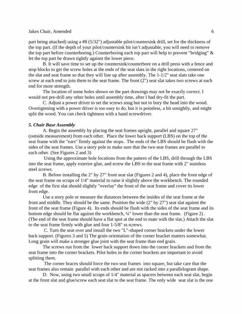
part being attached) using a #8 (5/32") adjustable pilot/countersink drill, set for the thickness ofthe top part. (If the depth of your pilot/countersink bit isn’t adjustable, you will need to removethe top part before counterboring.) Counterboring each top part will help to prevent “bridging” &let the top part be drawn tightly against the lower piece.
B. It will save time to set up the countersink/counterbore on a drill press with a fence andstop blocks to get the screw holes at the ends of the seat slats in the right locations, centered onthe slat and seat frame so that they will line up after assembly. The 1-1/2" seat slats take onescrew at each end to join them to the seat frame. The front (2") seat slat takes two screws at eachend for more strength.
The location of some holes shown on the part drawings may not be exactly correct. Iwould not pre-drill any other holes until assembly time, after I had dry-fit the part.
C. Adjust a power driver to set the screws snug but not to bury the head into the wood.Overtigtening with a power driver is too easy to do, but it is pointless, a bit unsightly, and mightsplit the wood. You can check tightness with a hand screwdriver.
5. Chair Base Assembly A. Begin the assembly by placing the seat frames upright, parallel and square 27"
(outside measurement) from each other. Place the lower back support (LBS) on the top of theseat frame with the "ears" firmly against the stops. The ends of the LBS should be flush with thesides of the seat frames. Use a story pole to make sure that the two seat frames are parallel toeach other. (See Figures 2 and 3)
Using the approximate hole locations from the pattern of the LBS, drill through the LBS into the seat frame, apply exterior glue, and screw the LBS to the seat frame with 2" stainlesssteel screws.
B. Before installing the 2" by 27" front seat slat (Figures 2 and 4), place the front edge ofthe seat frame on scraps of 1/4" material to raise it slightly above the workbench. The roundededge of the first slat should slightly "overlay" the front of the seat frame and cover its lowerfront edge.
Use a story pole or measure the distances between the insides of the seat frame at thefront and middle. They should be the same. Position the wide (2" by 27") seat slat against thefront of the seat frame (Figure 4). Its ends should be flush with the sides of the seat frame and itsbottom edge should be flat against the workbench, ¼" lower than the seat frame. (Figure 2) .(The end of the seat frame should have a flat spot at the end to mate with the slat.) Attach the slatto the seat frame firmly with glue and four 1-5/8" ss screws.
C. Turn the seat over and install the two "L"-shaped corner brackets under the lowerback support. (Figures 3 and 5) The grain orientation of the corner bracket matters somewhat.Long grain will make a stronger glue joint with the seat frame than end grain.
The screws run from the lower back support down into the corner brackets and from theseat frame into the corner brackets. Pilot holes in the corner brackets are important to avoidsplitting them.
The corner braces should force the two seat frames into square, but take care that theseat frames also remain parallel with each other and are not racked into a parallelogram shape.
D. Now, using two small scraps of 1/4" material as spacers between each seat slat, beginat the front slat and glue/screw each seat slat to the seat frame. The only wide seat slat is the one

Jakes Chair, Amended 7
used as the starter at the front. All others are the narrow ones. As you approach the back support in the rear, adjust your spacing to give an even spacing between the final 2-3 slats. Itmay be necessary to cut away part of the last slat to fit it under the LBS.
The narrow seat slats are important to the comfort of the chair. They may flex a bitwhen someone sits on the seat. On the other hand, if the slats at the back are too narrow (in orderto fit) they may be too weak unless you glue a secondary slat to the bottom to reinforce them.
6. Chair Arms and Back Assembly A. Install the arm braces to the outside, top, middle of the front legs, being sure that they
are flush with the top to support the arms. (Figures 2-4) The screws run from inside the front legsinto the arm braces.
B. Cut two scraps of wood 10-1/2" long and use them to support the front seat slat10-1/2" above the workbench. This should give an 18 E angle with the horizontal. The taper cutat the rear of the seat frame should now be horizontal, flat on the workbench. Clamp the frontlegs to the outside of the seat frame 3" back from the lower front tip of the seat frame (not thefront slat), being sure that the legs are plumb (Figure 2). Mark the position, apply glue, andscrew the legs to the seat frame. Add the secondary legs (stiffeners).
C. Pre-drill the four screw holes in the front of the arm runners, with the countersink onthe inside. Install the arm runner to the inside of the front legs, flush at the top and front of thefront legs, and level (assuming the workbench is level).(Figures 2-4) The four screws pass frominside the arm runners into the front legs. The arm runners should be parallel. Check the distancebetween them at the front and the back.)
D. Clamp the arms in position on the arm runners. The insides of the arms should beabout 1" from the inside of the arm runners. (Figures 2 and 4) The arms should be "bark side up".
E. Measure the distance between the outsides of the arms at the rear. Clamp the upperback support (UBS) under the arms, against the runners. Draw a guideline on the UBS that isflush with the arms at the outside and the rear.
F. The angle of the seat to the seat back should be between 90E and 100E. Figure 6 showsthe geometry required to get a seat angle of 100 E. The distance between an arbitrary point “A”,17" from the front of the LBS, and anarbitrary point “B”, 21" above the LBS,
Figure 6. Proportions to yield 100E Seat BackAngle

Jakes Chair, Amended 8
c If distance AB is 28", the seat angle will be 95E. If distance AB =27, the angle will be 90E.
should be 30". c Move the arms back or forward to adjust the seat angle and mark the undersideof the arms where they meet the front of the front legs.
E. Install the arms to the front legs and arm runners, trim the UBS to fit flush with theoutside and rear of the arms, and install the UBS to the arms with glue and three screws in atriangular pattern. (The triangular pattern is to avoid lining up the screws along the grain patternof the arm.)
F. Pre-drill two screw holes in the center back slat, d" from the bottom and ¾" fromeach edge. Install the center seat back slat, with the bottom of the slat flush with the bottom ofthe lower back support, in the center of the lower back support, and plumb from side to side. (Tomake it easier, you can clamp a support to the bottom of the LBS to hold the slat.) Then drill twoholes in the correct position at the UBS (¾" in from each edge of the back slat). Apply a thincoat of glue and screw the center back slat to the UBS. The bevel angle on the UBS shouldapproximately match the slope of the back slat.
G. Install the rest of the seat back slats (Figure 3). Work from the middle slat outward,keeping the inner bottom corner of the new slat touching the corner of the existing slat. There isno gap between slats at the bottom and equal gaps (a bit less than 1") at the top. Since the slatsfan outward toward the top by about ¾"-1" each, each slat will intersect an inner slat cornerslightly "lower down" on the lower back support in an arc. You may pre-drill the inner screwhole at the bottom of each slat but not the others, since its too hard to predict where the holesshould be until the slat is in place. You can lay a flexible steel ruler on the back slats to line upthe screws neatly.Use two screws at both the upper and lower back support contact points.
The outermost seat back slats are intended to clear the inside of the arms by about ¼". (Figure 4) I recommend spacing the slats all at once and adjusting them for uniform gaps at thetop. The final top of the chair back should measure about 26" at its widest point. Check the rearof the backslats for glue runs.
H. Install the back stretcher 11-12" above the UBS.I. Finally, turn the finished chair over and install nylon glides to each leg where it
contacts the ground.
7. Footstool Assembly A. Install the corner braces to the center of one end of each riser. Be sure that the edge
of the corner brace is flush with the end of the riser. Screw through the riser into the brace. B. Glue, clamp and screw the upper and lower footstool ends to the 12-1/2" tall risers,
screwing from inside out. (Figure 2) The footstool ends are installed on the "outside" of therisers.
C. Stand the risers up and plumb them with the corner braces to the inside on the top. Screw one of the narrow slats across the center of the top or the upper frame, covering up thecorner braces with the slat. Once screwed to the frames, using one screw on each end, screw twoadditional screws up from the corner brace into the bottom of the center slat. (Figure 4)
D. Screw each of the two wide slats to the lower frame on either side of the riser. Thiswill help to keep the two risers parallel and plumb for the remainder of the assembly. (Figure 5)
Jakes Chair, Amended 9
Finally, install the remaining slats to the upper frame and lower frame, spacing them equally(about ¼" apart).
E. Turn the finished footstool over and nail the four remaining nylon glides to the lowerfootstool ends.
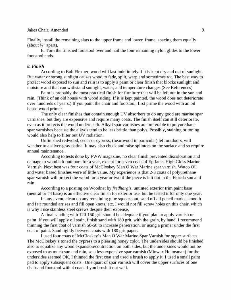
8. FinishAccording to Bob Flexner, wood will last indefinitely if it is kept dry and out of sunlight.
But water or strong sunlight causes wood to fade, split, warp and sometimes rot. The best way toprotect wood exposed to sun and rain is to apply a paint or clear finish that blocks sunlight andmoisture and that can withstand sunlight, water, and temperature changes.(See References)
Paint is probably the most practical finish for furniture that will be left out in the sun andrain. (Think of an old house with wood siding. If it is kept painted, the wood does not deteriorateover hundreds of years.) If you paint the chair and footstool, first prime the wood with an oilbased wood primer.
The only clear finishes that contain enough UV absorbers to do any good are marine sparvarnishes, but they are expensive and require many coats. The finish itself can still deteriorate,even as it protects the wood underneath. Alkyd spar varnishes are preferable to polyurethanespar varnishes because the alkyds tend to be less brittle than polys. Possibly, staining or toningwould also help to filter out UV radiation.
Unfinished redwood, cedar or cypress, (heartwood in particular) left outdoors, willweather to a silver-gray patina. It may also check and raise splinters on the surface and so requireannual maintenance.
According to tests done by FWW magazine, no clear finish prevented discoloration anddamage to wood left outdoors for a year, except for seven coats of Epifanes High Gloss MarineVarnish. Next best was four coats of McCloskey Man O War Marine spar varnish. Watco Oiland water based finishes were of little value. My experience is that 2-3 coats of polyurethanespar varnish will protect the wood for a year or two if the piece is left out in the Florida sun andrain.
According to a posting on Woodnet by fredhargis, untinted exterior trim paint base(neutral or #4 base) is an effective clear finish for exterior use, but he tested it for only one year.
In any event, clean up any remaining glue squeezeout, sand off all pencil marks, smoothand fair rounded arrises and fill open knots, etc. I would not fill screw holes on this chair, whichis why I use stainless steel screws despite their expense.
A final sanding with 120-150 grit should be adequate if you plan to apply varnish orpaint. If you will apply oil stain, finish sand with 180 grit, with the grain, by hand. I recommendthinning the first coat of varnish 50-50 to increase penetration, or using a primer under the firstcoat of paint. Sand lightly between coats with 180 grit paper.
I used four coats of McCloskey’s Man O War Marine Spar Varnish for upper surfaces.The McCloskey’s toned the cypress to a pleasing honey color. The undersides should be finishedalso to equalize any wood expansion/contraction on both sides, but the undersides would not beexposed to as much sun and rain, so a less expensive spar varnish (Minwax Helmsman) for theundersides seemed OK. I thinned the first coat and used a brush to apply it. I used a small paintpad to apply subsequent coats. One quart of spar varnish will cover the upper surfaces of onechair and footstool with 4 coats if you brush it out well.

Jakes Chair, Amended 10
References
Tom Begnall, Torture Test for Outdoor Finishes, FWW May/June 2009
Bob Flexner, Protecting Exterior Wood, American Painting Contractor, DouglasPublications, April 1999.
Forest Products Laboratory. 1999. Wood handbook—Wood as an engineering material.Gen. Tech. Rep. FPL–GTR–113. Madison, WI: U.S. Department of Agriculture, Forest Service,Forest Products Laboratory.
Figure 7. Scale Drawing of the Arm for Jakes Chair, Amended

Jakes Chair, Amended 11
Gauldin’s Notes for Jake's Chair Drawings (Files P1.bmp - P12.bmp)
- - - A dashed line indicates that the edge should be rounded over on both sides. Therecommended rounding bit has a 3/8" radius. Some of the dotted lines used to indicate edgerounding make the drawing harder to understand, so a small drawing of the part with solid linesis included. ___ A solid line indicates the edge should be sharp on both sides (you might want to soften theedges a bit) • All dimensions are in inches. • All drawings are made to scale (exceptions are noted), but each drawing is to a different
scale. A 10" line is drawn on each drawing to show the scale • The actual shape of non-dimensioned surfaces is left to your discretion, Just draw a smooth
curve to fill in the shape • NTS means "not to scale". TYP means the other similar features have the same dimension. R
32.5 means the indicated dimension is a 32.5" radius • The screw holes are drawn over-scale. They should be clearance holes for the screws you use
to assemble the chair. Note that it is probably better to drill the holes while you areassembling the chair, rather than drilling them ahead of time
Rough Cut List (Boards are ¾" finished thickness except for #1 and #3
No. Quantity Name Rough Dimensions
1 2 Seat frame 7 x 38" x 1"(actualthickness)
2 2 Arm 7 x 29 x ¾
3 3 Front Leg 3.5 x 25 x 1" (actualthickness)
4 1 Upper Back Support(Brace)
6 x 32" (rough dimensionof blank)
5 1 Lower Back Support(Brace)
6 x 27" (rough dimensionof blank)
6 4 Footstool End 2 e x 12
7 2 Arm Support 3 ¼ x 16
8 1 Back Slat Assembly
7 Back Slat 3.25 x 31
9 2 Arm Runner 3.25 x 23.5
Jakes Chair, Amended 12
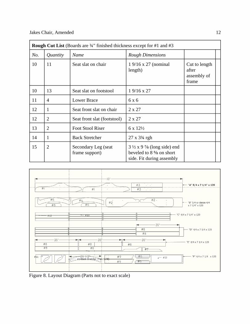
Rough Cut List (Boards are ¾" finished thickness except for #1 and #3
No. Quantity Name Rough Dimensions
10 11 Seat slat on chair 1 9/16 x 27 (nominallength)
Cut to lengthafterassembly offrame
10 13 Seat slat on footstool 1 9/16 x 27
11 4 Lower Brace 6 x 6
12 1 Seat front slat on chair 2 x 27
12 2 Seat front slat (footstool) 2 x 27
13 2 Foot Stool Riser 6 x 12½
14 1 Back Stretcher 27 x 3¾ rgh
15 2 Secondary Leg (seatframe support)
3 ½ x 9 f (long side) endbeveled to 8 e on shortside. Fit during assembly
Figure 8. Layout Diagram (Parts not to exact scale)
Jakes Chair, Amended 13
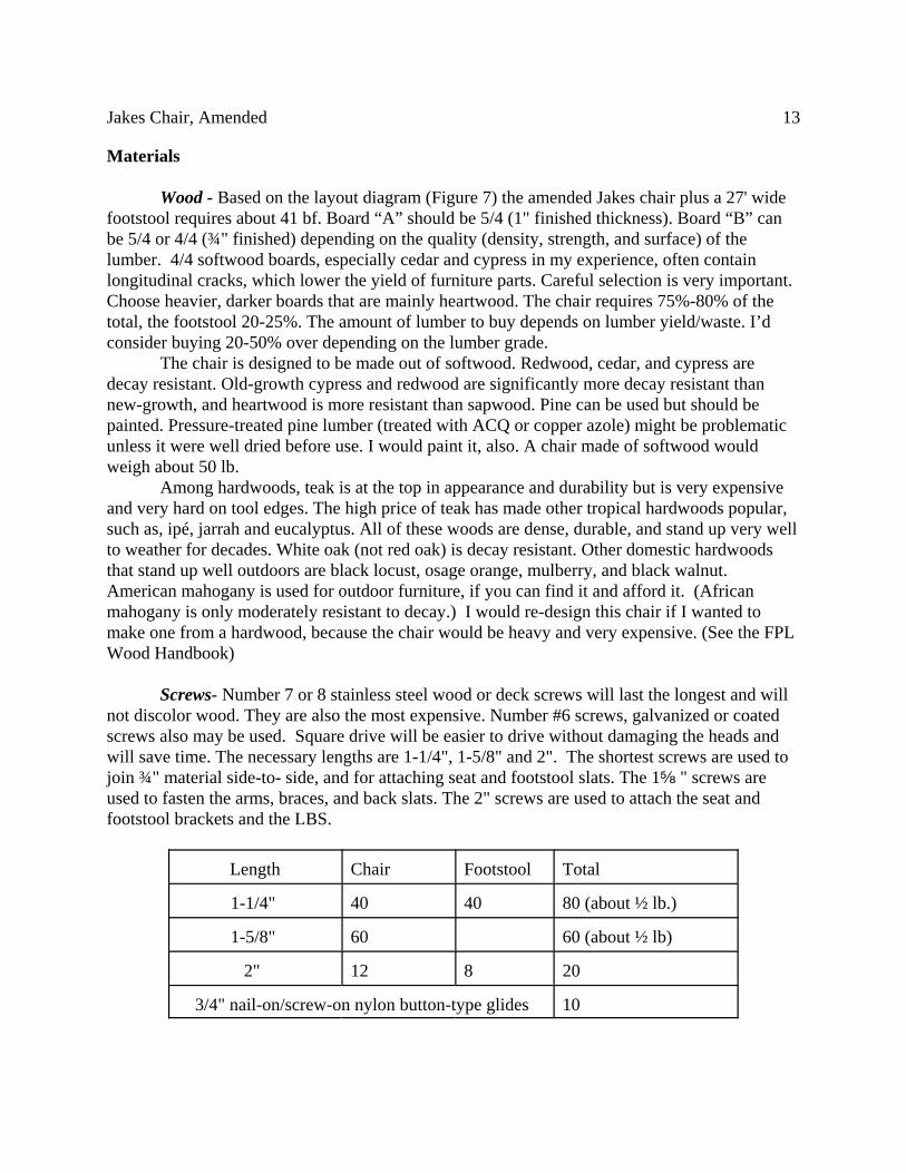
Materials
Wood - Based on the layout diagram (Figure 7) the amended Jakes chair plus a 27' widefootstool requires about 41 bf. Board “A” should be 5/4 (1" finished thickness). Board “B” canbe 5/4 or 4/4 (¾" finished) depending on the quality (density, strength, and surface) of thelumber. 4/4 softwood boards, especially cedar and cypress in my experience, often containlongitudinal cracks, which lower the yield of furniture parts. Careful selection is very important.Choose heavier, darker boards that are mainly heartwood. The chair requires 75%-80% of thetotal, the footstool 20-25%. The amount of lumber to buy depends on lumber yield/waste. I’dconsider buying 20-50% over depending on the lumber grade.
The chair is designed to be made out of softwood. Redwood, cedar, and cypress aredecay resistant. Old-growth cypress and redwood are significantly more decay resistant thannew-growth, and heartwood is more resistant than sapwood. Pine can be used but should bepainted. Pressure-treated pine lumber (treated with ACQ or copper azole) might be problematicunless it were well dried before use. I would paint it, also. A chair made of softwood wouldweigh about 50 lb.
Among hardwoods, teak is at the top in appearance and durability but is very expensiveand very hard on tool edges. The high price of teak has made other tropical hardwoods popular,such as, ipé, jarrah and eucalyptus. All of these woods are dense, durable, and stand up very wellto weather for decades. White oak (not red oak) is decay resistant. Other domestic hardwoodsthat stand up well outdoors are black locust, osage orange, mulberry, and black walnut.American mahogany is used for outdoor furniture, if you can find it and afford it. (Africanmahogany is only moderately resistant to decay.) I would re-design this chair if I wanted tomake one from a hardwood, because the chair would be heavy and very expensive. (See the FPLWood Handbook)
Screws- Number 7 or 8 stainless steel wood or deck screws will last the longest and willnot discolor wood. They are also the most expensive. Number #6 screws, galvanized or coatedscrews also may be used. Square drive will be easier to drive without damaging the heads andwill save time. The necessary lengths are 1-1/4", 1-5/8" and 2". The shortest screws are used tojoin ¾" material side-to- side, and for attaching seat and footstool slats. The 1e " screws areused to fasten the arms, braces, and back slats. The 2" screws are used to attach the seat andfootstool brackets and the LBS.
Length Chair Footstool Total
1-1/4" 40 40 80 (about ½ lb.)
1-5/8" 60 60 (about ½ lb)
2" 12 8 20
3/4" nail-on/screw-on nylon button-type glides 10