
Jack/TTES: A System for Production and Real-Time Playback ...
38
University of Pennsylvania University of Pennsylvania ScholarlyCommons ScholarlyCommons Technical Reports (CIS) Department of Computer & Information Science August 1994 Jack/TTES: A System for Production and Real-Time Playback of /TTES: A System for Production and Real-Time Playback of Human Figure Motion in a DIS Environment Human Figure Motion in a DIS Environment John P. Granieri University of Pennsylvania Follow this and additional works at: https://repository.upenn.edu/cis_reports Recommended Citation Recommended Citation John P. Granieri, "Jack/TTES: A System for Production and Real-Time Playback of Human Figure Motion in a DIS Environment", . August 1994. University of Pennsylvania Department of Computer and Information Science Technical Report No. MS-CIS-94-42. This paper is posted at ScholarlyCommons. https://repository.upenn.edu/cis_reports/488 For more information, please contact [email protected].
Transcript of Jack/TTES: A System for Production and Real-Time Playback ...

University of Pennsylvania University of Pennsylvania
ScholarlyCommons ScholarlyCommons
Technical Reports (CIS) Department of Computer & Information Science
August 1994
Jack/TTES: A System for Production and Real-Time Playback of /TTES: A System for Production and Real-Time Playback of
Human Figure Motion in a DIS Environment Human Figure Motion in a DIS Environment
John P. Granieri University of Pennsylvania
Follow this and additional works at: https://repository.upenn.edu/cis_reports
Recommended Citation Recommended Citation John P. Granieri, "Jack/TTES: A System for Production and Real-Time Playback of Human Figure Motion in a DIS Environment", . August 1994.
University of Pennsylvania Department of Computer and Information Science Technical Report No. MS-CIS-94-42.
This paper is posted at ScholarlyCommons. https://repository.upenn.edu/cis_reports/488 For more information, please contact [email protected].

Jack/TTES: A System for Production and Real-Time Playback of Human Figure /TTES: A System for Production and Real-Time Playback of Human Figure Motion in a DIS Environment Motion in a DIS Environment
Abstract Abstract This document describes a modified Jack system for off-line motion production and on-line (real-time) motion playback to an external IRIS-Performer-based host rendering system. This work was done in partial fulfillment of Contract #N61339-94-C-0005 for the US Marine Corps through NAWCTSD (Naval Air Warfare Center, Training Systems Division). The work described herein was contributed by several of the members of the Center for Human Modeling and Simulation: John Granieri (Design/Engineering/Integration), Rama Bindiganavale (animator, posture transitions), Hanns-Oskar Poor (animator, posture transitions, Hyeongseok Ko (walking and running motion), Micheal Hollick (locomotion playback control), Bond-Jay Ting (body sculpting), Francisco Azoula (body sculptin, anthropometry), Pei-Hwa Ho (body normalization), Jonathan Crabtree (Performaer, TIPS file format), Xinmin Zhao (slaving), Zhongyang Feng (DIS logfile player), Welton Becket and Barry Reich (terrain reasoning and reactive agent control).
Comments Comments University of Pennsylvania Department of Computer and Information Science Technical Report No. MS-CIS-94-42.
This technical report is available at ScholarlyCommons: https://repository.upenn.edu/cis_reports/488
JacklTTES: A System for Product ion and Real-time Playback of Human Figure Motion in a DIS
Environment
MS-CIS-94-42 HUMAN MODELING & SIMULATION LAB 65
John P. Granieri
University of Pennsylvania School of Engineering and Applied Science
Computer and Information Science Department
Philadelphia, PA 19104-6389
August 1994


JacklTTES: A System for Production and Real-time Playback of Human Figure Motion in a DIS Environment
John P. Granieri Center for Human Modeling and Simulation
University of Pennsylvania Philadelphia, PA 19104-6389, U S A
August 5 , 1994
1 Overview
This document describes a modified Jack system for off-line motion production and on-l~nc ( r ea l - t i~~ r t ,~ motion playback to an external IRIS-Performer-based host rendering system. This work was do11c8 1 1 1
partial fulfillment of Contract #N61339-94-C-0005for the US Marine Corps through KAIVCTSD ( N a v i ~ l
Air Warfare Center, Training Systems Division). The work described herein was contributed by several of the members of the Center for lIurnitl~
Modeling and Simulation: J o h n Granier i (Design / Engineering / Integration), R a m a Bindigarlavalc, (animator, posture transitions), Hanns-Oskar P o r r (animator, posture transitions), Hyeongseok K o (walking and running motion), Micheal Hollick (locomotion playback control), Bond-Jay Ting (hotl!- sculpting), f i a n s i s c o Azoula (body sculpting, anthropometry), Pei-Hwa H o (body normalizatior~ j .
J o n a t h a n C r a b t r e e (Performer, TIPS file format), X inmin Zhao (slaving), Zhongyang Feng (111s logfile player), We l ton Becket and B a r r y Reich (terrain reasoning and reactive agent control).
2 Description of JackITTES
The Team Tactical Engagement Simulator (TTES) system is being designed and built, a t NAWCTSI) i l l
Orlando, Florida. This system projects one or more soldiers into a virtual environment, where they nlay engage hostile forces. The hostiles throw stones and fire their weapons a t the soldier. See Figure 1 for n schematic overview of the system components. For a full description of TTES refer to the proceedings of INCOMSS-94, where a presentation regarding TTES was made.
The soldier stands in front of a large projection screen, which is his view into the environment. HI! has a sensor on his head and one.on his weapon. He locomotes through the environment by s t e p p i ~ ~ g on a resistive pad and controls direction of movement and field of gaze by turning his head. The soldicr may also move off the movement pad, and the view frustum is updated accordingly based on his vc. position (head-coupled display). This allows the soldier, for example, to crouch down to ser undw ;I
parked vehicle, or to peek around the corner of a building while still affording himself the protection of the building.
Essentially. both the hostiles and the soldier can move around the environment and engage racll other. The 11ost.iIes are controlled via a DIS stream of commands coming from a computer-generatetl forces (CGF) simulator. (The CGF system is currently under construction a t the Institute for Simirlatio~~ and Training, Orlando, FL. I think they are calling it "SAFDI"). The TTES filters and trarls1at.e~ tllc.
DIS st.ream into a set, of posture and command "tokens" that are passed to Jack. .Jock then animate.< t

human figures by transitioning from one posture to another, or locomoting in a cyclical posture change. Jack passes the joint angles back to T T E S for animating in an IRIS Performer run-time articulat.ed database of human geometry.
The T T E S I J a c k connection is made through two T C P / I P stream sockets (The first incarnat.ion of the interface was done with shared-memory. This was dropped in favor of the flexibility of the socket interface - the machine Jack runs on and the machine TTES runs on don't have to be the same, althougll they can be).
T T E S controls the global position of each human figure (Jack only moves the figures in its local coordinates), using DIS dead-reckoning algorithms and information about the terrain. The posr ttrc, transitions are recorded in such a way that the direction of the face and gun are al\vays in a kllon.lt direction, so the human can be globally oriented correctly when it fires its weapon TTES also crc,ntt.. the necessary DIS Entity State PDUs to represent the real soldier (mapping fro111 scnsor v;llr~c..; i111o t 1 1 , small set, of postures in the Entity State PDU), and sends them out over t l l ~ l~et lo I I I P ( ' ( ; I . ' .;!..tr,rl~ ; I I I , I o t l~e r T T E S stations that are participating in the exercise. T T E S also pcrfor~~ls 111t. I~nl l i s~ ics ( c . o r ~ ~ l ~ ~ ~ r : i t 1 1 1 1 1
for firing the soldier's gun iilto the scene and determining if and where ~ I I c , I I O S I i l l * I I I I I I I ; I I I li;~rrt.\ :,.I 1 1 1 :
3 Description of Implementation
Below, I summarize the implementation details of modifications to Jack and the T T E S s t r~ l ) progralll I \! 1
do not, have an actual T T E S trainer station) which mimics the communications ~nt~rfncc) and ~ C I I C I V ~ I I I L of the real TTES program with Jack.
3.1 DIS Protocol
The information representing the human entity in the simulation is limited by what. is stored i n all I-;IIIII! State Protocol Data Unit (PDU) in the DIS protocol. The information we are interested in fronl 1111. 1:s PDI: is shown in Figure 2. The human is always in one of the 4 postures, along with a weapolt S I ; I I ~ .
We only modeled the two values of the weapon state, d e p l o y e d and firing, and not. s l o u ) e d (which \vou l t i
represent the gun slung over the shoulder or something like that) . The DIS protocol also allows for upto three weapons on a soldier, but we only modeled one. illso I 1 1 1 ,
protocol allows for a large library of weapon types to fit on the soldier (i.e. pistols, grenades. ~ n a c l l r ~ ~ ( guns, blow pipes, knives, etc). We only modeled AK-47 and M I 6 machine guns.
3.2 Posture Transitions - Static In t h t case where the magnitude of the velocity vector is zero (meaning the human is not movingj. \ \ . I ,
want I ( , transition between the possible static postures. We encoded the possible static st.ates of 1 1 1 1 .
11urna11 in a posture graph, where the nodes represent static postures, and the directed arcs represet11 t I t ( ,
animated transit.ions, or movement, from posture t o posture. The possible transitions between static postures are encoded in the posture graph of Figure :1. '1'111,
actual postures are shown in Figure 4. Each directed transition from posture A to B has art assoc.~- at.ed motion file, which scripts the transition on the standard human figure a t the origin of t11v .l(rrX. environment. For example, the transition between (Standing Stowed) and (Standing Firing) is i l l a f i le . s t s t o w a s t f i r e m o t i o n s . env. For several transitions between A and B, we only author a directed I rarl- sitiorl from A t o B, and to go from B to A, we simply play the transition backwards. Each nlot,ior~ lilt. typically h a s about 10-15 primitive Jack motions to transition the human and the gun from one post,urc. to another.
I n general, a given posture transition was first studied from a video tape of a soldier, as supplirtl by NAWCTSD ( the movie files are supplied on the tape). The goal was not so much as to completrly recreate the motion in Jack but more to treat the video as a visual template for the movemellt. I-or instance. i t . served as an example of where the arms where in relation to the feet, or what dirrctio~r t l t ~ .


Figure 2: Essential information from the Entit'y State PDU
Field
Posture Weapon Position Velocity Heading
Figure 3: The posture transition graph
slio~rlder was tilted, or the general timing of the individual movements of the body in relation to each other.
O n c ~ t,he individual body segment movements were visually recognized and isolated, the animat.ors set out t o create corresponding movements in Jack using its goal-oriented motion facilities. To facilitat,? t.he cre;it.ion, i t was found helpful to display the figure and the respective motion from several angles on the screen, which helped in the precise placement of the limbs in 3D space.
There was a restriction that the ending posture of a posture transition had to be identical 1.0 t.hc starting posture of the next posture transition. This was no problem when we created motions in the forward direction (e.g.. Stand to Kneel). But when we had to create the motions in the reverse d i rec t io~~ (lineel t o Stand) , it was very difficult to get the ending posture to a particular position (joint angles. displacements, torso position, etc had t o coincide exactly) and still get "good7' motions. This dificulty was overcome by creating mostly forward-moving motions, and then using the abi1it.y to play channelsets in reverse (see below), to get. the corresponding reverse direction, as described above. In most. cases. the resulting motions looked fine. In a few cases, the reverse motion was scripted explicitly for het,t.er results.
Also, we at.tempted to only animate those sequences which were absolutely neccessary. For example. we have no direct transition from Prone Firing to Kneeling Firing. The run-time system can find the shortest pat,ll (in time) between any two postures in the graph, and execute the sequence of t.ransitions.
Value
sf nndzng, kneeinng, prone, deslroyed (Stowed) , Deployed, Fzrzng
P,, Py , P, V z , Vy, \Iz
theta
Units
meters meters/second compass heading in degrees

Figure 4: The postures a soldier can take in DIS
3.3 Posture Transitions - Dynamic/Cyclic
IYhen the magnitude of the velocity vector is not equal t o zero, the soldier is moving (either forwards or backwards, depending on the difference between the heading and the direction of the velocity vector) by either locomoting (if appearance is upright) or crawling (if appearance is prone). When the soldier is moving, we call this a dynamic or cyclical posture transition.
T h e animations were generated by Hyeongseok KO's walking system. He generated 6 strides for each t.pe of walking (forward walking, backward walking, running): left and right starting steps ( tha t go from the base posture to the cyclic state), left and right ending steps (that go from the cyclic state to the base posture), and left and right cyclic steps. T h e crawling animation was generated manually, and is based on two animations - one that goes from the base (prone) posture t o the cyclic state, and one complete cyclic motion. When crawling is ending the starting animation is played backwards to get back to the base posture.
Playback control of the animation frames is based on a simple state machine shown in Figure 5 l .
jl'alking is begun whenever the velocity of a figure goes from zero to a non-zero value. The heading and velocity vector are compared a t this time t o determine whether the figure is walking forwards or 1,ackwards. Once t.his determination is made, the appropriate animation information is referenced and used. T h e purpose of this initial step is to create a smooth transition from the base posture (standing deployed) t o the walking animation.
\?'hen the first step is finished, the cyclic "walking" s ta te is started. This s ta te continues to generate l~orrnal walking motions until the velocity goes back t o zero (a t which time the ending step is used), or tile velocity becomes greater than the walkjrun transition value. If this occurs, and if the figure is walking forwards (there is no backwards running), the running animations are referenced and used. Therc is a single walk->run transition step that is played, then the "running" cyclic state is entered. Tlle figure will continue to run until the velocity drops below the threshold, a t which t ime the run->walk step will be used. and the "walking" state will be re-entered.
'Note that in this graph, the nodes are posture transitions that can loop, or states, and the arcs are c o n d i t i o n s to transit ion bet.ween states

Standing n
v < = o
Walk Step LIR O < V C = I
Start Run LIR
Run LIR i+i'v<t For ~ n n i n g . r=3 meters/second If v < 0. walking and crawling is backwards (no running backwards)
Prone
Figure 5 : The walking/running/crawling state transition graph
V
v > 0
Stadstop Crawl A
v < = 0

3.4 Preparation for Motion Playback
Once the individual soldier motions/transitions were authored, they were recorded to channelset files and organized together into posfure graph files. Then they are re-recorded onto lower-resolution soldier figures, and then loaded and bound for playback to the TTES program. I'll describe each phase, along with the corresponding Jack commands which do the work.
3.4.1 R e c o r d i n g to C h a n n e l s e t s
LYhen you create a regular motion in Jack and then execute go, the interpolated frame motion is stored in a channel. A channel is storage for any time-varying pardmeter. For example, each joint in the environment has its own channel to store the angles . The channels are tightly bound t.o each object for which they store data. I added two new objects to Jack and Peabody. a channelset and a sharedchannel. A sharedchannel holds the same data as a channel, except 1 1 is not bound to a specific object in the environment. This allows it to share its data between several objects of the same type (here, the term objecf means either a joint(angles) or a figure(position)). A channelset organizes a set of sharedchannels together, giving them a name and a couple of other parameters. Channelsets are used to store the posture transitions and other motions described above. Each motion sequence, once it is interpolated in Jack, is saved as a channelset file (including only those channels from the environment that are part of the soldier and gun).
Once a channelset is created and loaded into Jack the sharedchannels can be bound to objects in the environment. Each sharedchannel can be bound to many objects (of the same type). For example, a sharedchannel containing joint angle data for the left knee can be bound to all figures (of the appropriate type) with a left knee. A bound channelset is called, of course, a bound channelset. The amount. of memory required to bind a channelset is very small in comparison to the size of the data in a channelset.
A channelset is a Peabody construct, stored in an environment file. An example channelset is shown in Figure 6.
Both a channelset and a sharedchannel have a name associated with them, but it is arbitrary (it doesn't relate t o any Peabody construct), but it should be descriptive (as in the above example). The Peahody fields of the channelset are:
s i ze : T h i s is the number of frames stored in each sharedchannel in the set.
c o u n t : The number of sharedchannels in the set.
f p s : T h e frames-per-second that the set was saved at . From this, one can deduce the actual time represented in this set. For example, if size=90 and fps=60, then this set represents (90160) or 1.5 seconds. This also alerts the sampling functions on the sampling frequency for the motion.
Sharedchannels must be declared within a channelset construct. There are no restrictions on the number or type of sharedchannels in a channelset. For TTES each channelset usually contains two figure channels (for the soldier and gun) and joint channels for the soldier. The fields of a sharedcliannel are:
t y p e : This is either "sharedfigure" or "sharedjoint" for now, denoting a figure channel (figure location) or a joint channel (joint angles).
o b j e c t : In the case of a "sharedfigure" channel, this is a string which just holds the figure name of the figure from whence this channel was recorded, and is not used after created. In the case of a "sharedjoint" channel, i t is the name of the joint, and will be used to locate a joint to bind to.
p ro tof i l e type : This is the name (without path prefix) of the figure file from which this object came. I t is used when the channel is bound. This channel can only be bound to objects which have the same figure file name (this is a matching criteria for sharing).

I 1 channelse t crawl2prstoa. chset {
s i z e = 48; f p s = 60; count = 70; sharedchannel s o l d i e r { / * f i g u r e p o s i t i o n */
type = "sharedf igure" ; protof i l e t ype = "so ld ierxam. f ig" ; ob jec t = " so ld i e r " ; frame[O] = ("lower-tors~.proximal~~, trans(31.68cm,43.53cm,-31.05cm)) ; frame [l] = ("lower-torso.proxima1" , trans(31.68cm.42.77cm, -31 -05cm)) ;
frame [48] = ("lower-torso .proximal1', trans(11.52cm,4.15cm, - 2 6 . 4 9 ~ ~ ) ) ;
1 sharedchannel r i gh t - t oe s { /* j o i n t angles */
type = "sharedjo in t" ; p ro tof i l e t ype = "soldier-cam.f ig l ' ; ob j ec t = "right- toes"; /* R(y) */ frame [ O l = (0) ; frameC11 = (0) ;
frame C481 = (0) ;
1
I I
Figure 6: An Example Channelset f i l e

frame[?] : This is the frame data , indexed per frame. For figures, it's a root site and a transform. For joints, it 's the joint angles (in radians). The Peabody parser was modified to allo\i~ field names with indices.
Rlost of the channelsets for TTES were recorded at 60Hz, to provide for better motion sampling. and the ability to vary playback tlme (see posture graph files below).
T h e commands added t o J a c k for working with channelsets are the following:
write-channelset : This command will create a new channelset file, from currently defined (and int.rr- polated) channels in the environment (i.e. after you've create some motions and typed go). TIIV command prompts for an output file and a channelset, name: followed be t,he begining ant1 e n d ~ n g frame numbers (of current motions) to grab frames from. The nonlenclature for cl~aiinrlsc~t I l ; l r l l r ' i
are any valid Peabody identifier, without the "/" character. I t also prompts for a fils and btrltlt value. For example, i f begin=100, end=220, fps=30, and stride=2. you'd tic, pulling 60 fra~tlc%.\, o r
2 seconds, of niot.ion from fra.mes (100, 102. 104. ... . 220)). It also ~ ) r o ~ i i p t i for i1 1 1 ~ 1 o f i igr~r, , i and the channelset will be created wit11 all the channels (figure pos~tion ant1 joint i~~iglv!-) rr0111 I 1 1 , list of figures. In t.he case of TTES we always included a soldier and a gull.
load-channelset : This command prompts for a channelset file (an .env filc). and rcads i t . T l ~ c channelset is built via the call-outs from the Peabody parser. The channelsets car). alternativcl!.. just be loaded via the read3 ile command. The channelsets will have their names correspontl~rrg to what they were named when written.
bind-channelset : This command prompts for a channelset (from the list. of loaded charit~elsets). i111(1
then for a new name for the bound channelset you are creating. It then proceeds t o creatc ;I ~ r c ~ n .
bound channelset, prompting you for figures of the appropriate types (i.e. from the protofi1c.- type fields of the sharedchannels). For example, if the channelset name you are binding is c a l l ~ ~ l "stand2crawl". and you are binding this to the 3rd soldier-gun pair, where the soldier's figurr tlnrllt. is "soldier3". then a good name for the bound channelset would be "stand2crawl/soldier3"
play-bound-channelset : Once a bound channelset is created, you can play i t . This corllmand prompt.\ for a bound channelset, as well as a direction (forwards or backwards) and a transition tinic- j - 1 means play it at the stored time), and then will play the motion.
step-bound-channelset : Similar to the above command, but allows you to single-step the frames. for debugging purposes.
set-channelset-parameters : This command sets the only global parameter concerning bouird c11w11- nelset playback: "yes" means play the bound channelset by traversing each frame, so you'll see t I I V complete motion, as fast as i t can be drawn (which most likely is less than 30%). or "no" nn?an+ play the motion in real-time, sync'd to a real-time clock. This will skip frames, so the m o t ~ o n play< back in true "wall-clock" time. The setting should be "no" during playback to TTES.
print-channelsetinfo : This command will print information, a t several levels of verbosity, at)our memory usage and contents of stored channelsets.
rerootf igure-channel : This is a utility command, which operates on a channel (not a sl~aredchannel or a hound shared channel). Its purpose is t o re-root a figure position channel so all the root sit(, references are the same. For example, in the motion data recorded from the walking a l g o r i t h ~ i ~ . t h i , figure root moves all over the place ( the toes, heels, hips, pelvis). and we want to transform 11 so all references are to the pelvis (for performance, the soldier figures are never re-rooted during motloll playback, although it is possible). The command simply prompts for a figure root site. then finds t,lie corresponding channel, then plays it out . re-rooting to the new site. and re-recording over t i r ~ old posit ion da ta as it goes. This command can take a while to execute.

3.4.2 P o s t u r e G r a p h files
The channelsets can be organized into posture graph files, for easier loading, and optionally, for motion playback (only the static posture transitions make use of posture graphs; the walking and running control code only uses post.ure graph files as a convenience for storing channelset motions).
An example posture graph file (for the static posture transitions of the D1.f i g (See Section 3.4.3 below), as shown in Figure 3 , is shown in Figure 7.
The file is divided in 3 sections. The first section introduces the tokens for the nodes of the graph (the static posture). The second section just lists the channelset files for all motion, and assigns a number to each. The third section describes the actual direcbed arcs, or transitions, in the graph. Each l i n ~ start.+ with the beginning and ending posture, followed by the numSer of the channelset to play. Fol1on.rni: that is the direction of play on the channelset, and the time it should take for traversal. If you c l l ; t l ~ :~
the timing here, the playback system will sample the motions accordingly. The following commands in Jack are for dealing with posture graphs. Note that therc is cr~rrc~itI> 1 1 ,
comnland for creating a posture graph file. They are usually created via t Ile I.niversal Data Al i~n l j )~~ l ; i~ o r
(a.k.a. gnu-emacs).
load-posturegraph : This command prompts for, then loads a posture graph file By con \cn t~o~l t l l c
suffix for the posture graph file is .graph. It also asks for a name to give the posture graph ?'Ills name will be used later for reference Once the actual graph 1s loaded. all the channelsets will loaded also.
bind-posturegraph : This command will take a posture graph, and create a bound posfurr gmpii analogous to the channelsets and bound channelsets. It prompts for a posture graph, and a I I ~ , \ \
name for the new graph. I usually just add a prefix like "soldier3/" to the postlure graph nanic. .<(I
if the posture graph name was "ptrans", then the bound posture graph is "soldier3/ptrans"
It also traverses the channelsets and collects all the unique protofigfile fields, and prompts yo11
to pick a figure of each kind. It then creates bound sharedchannels (bound channelset) for cac.ll channelset. The bound channels then are named something like "soldier3/ptrans/ststow~cran.1" (i.e. they are prefixed by the bound posture graph name). The names are not so important. J I I S I
as long as they make some kind of sense.
posture-change : This command lets you test out a posture graph. It prompts for a bound posturl graph, and then one of the nodes of the posture graph. I t will then search for a path from t l ~ e r u r - rent node to the target node in the posture graph (shortest path as defined by traversal time). a11tl then execute the set of transitions. For example, if the bound posture graph is currently a t STAN1)- I N G S T O W E D , and you request PRONE-FIRING, i t will transition from STANDSTO\VED to CRAi1'L to PRONESTOWED then t o PRONE-FIRING.
. lorX uses three posture graph files for the TTES simulation: so ld ie r low.graph holds the s t a t ~ c PO.\-
t ure transition graph, s o l d i e r l o c o . graph holds the walking and running transitions, and soldier-crawl . graph llolds the crawling transitions. Note that the last two aren't proper posture graphs in the preceding senscl. bu t are just used for convenience for storing and creating bound channelsets.
Note that when a posture transition is requested, the system will sample the pre-recorded mot1011 at the frame rate frequency, so it is guaranteed to always play back in real time. For a 2 second posturc, transition recorded a t 6Ofps, and a current frame rate of the image generator of 20fps, the playbacl; system plays frames 0, 3, 6 , ..., 120. It recomputes the elapsed time on every frame, in case the franic rate is not uniform.
3.4.3 L o w e r reso lu t ion body model
Because of frame-rate requirements and polygon-count restrictions, it was necessary to build a lower resolutio~l human figure for use in the runtime TTES system. The low res soldier figure (DI . f i g ) 11w tllc following properties, compared to the regular, polybody human:

// First, the posture names and posture tokens // (they must start at 0, and be consecutively numbered) 8 / / number of posture states 0 STANDSTOWED 1 STANDPIRE 2 KNEELSTOUED 3 RNEELIIRE 4 PRONESTOWED 5 PRONE-FIRE 6 CRAWL 7 DEAD # marks end-of-postures / / / / Now, the posture transition tokens, and channelset filenames / / (they must start at 0, and be consecutively numbered) //token filename 1 7 / / number of transition files 0 ststow2stfirelow.chset.env 1 ststow2kstovlow.chset.env 2 ststow2crawllov.chset.env 3 ststow2kfirelow.chset.env
1 4 prstow2deadlow.chset.env 15 prfire2deadlow.chset.env 1 6 stf ire2kstowlov.chset .env # marks end-of-postures-transitions / / Now, the actual transitions (arcs in the graph) / / / / start end channelset playback time STANDSTOUED STAND-FIRE 0 forward 0 . 8 STANDIIRE STANDSTOWED 0 backward 0 .8 STANDSTOWED KNEELSTOWED 1 forward 1.6 KNEELSTOWED STANDSTOWED 1 backward 1.6
PRONE-FIRE DEAD 1 5 forward 0.8 STANDPIRE KNEELSTOWED 1 6 forward 1 . 6 KNEELSTOUED STANDPIRE 1 6 backward 1 . 6 DEAD STANDSTOWED 4 backward 1 0 . 0 # marks end-of-arcs
Figure 7: A Posture Graph file

The D I .f i g emulates the polybody in most every detail, except that it has no fingers (fingers and palm are a single segment), no spine, no eyeballs, and no clavicle psurf (i.e.. the clavicle is a virt.ual segment). Tlie DI . f i g link structure is t,he same as the polybody, except for hands (no fingers) and spine ( t h ~ spine was replaced with two rotational joints, and one translational joint, to mimic the compression t Irat the normal spine can do). The geometry of the segments of D I . f i g were not normalized, nlaktt~g 1 1
un-scalable (anthr~~ometr ical lv)? . Currently: DI .f i g has the dirrlensions of a 95th percentile n ~ a l r a..
defined in ANSUR 88, as given by SASS v2.2.1.
3.4.4 Slaving and re-recording
Because of the difference in internal joint structure between the s o l d i e r . f i g and DI . f i g , it,s mot ion cannot be controlled by the available human control routines in Jack (which all make assumptiot~s ahout the structure of the human figure). Instead of controlling its motion directly, we use the existing comnlands to control the motion of the regular human (as described above) and map the motion on to the low resolution figure, DI.fig. We call this process slavzng, because the high resolution f i g u r ~ is the,
master, and the low resolution figure is the slave. N'e use Jack's constraint system to do the slaving. Even though the two figures have different internal
joint struct,ures. their dimensions (e.g., length of arms? legs, etc.) are the same. Our goal is have the important landmark sites on both bodies match during the motion. Since from waist down the t w o figures have the same internal joint structure, we can simply copy the joint angles. From waist up. constraints are used to insure the motions of the two figures match. We create one constraint for each sit.? to be matched. The important sites to be matched are (and the respective constraints):
1 Constraint I endeffector (on D I .f ig) I goal (on soldier .f ig) ( joint chain (on D I . f i g ) / I 11 ~ 1 - b e l l v / middle-torso.ur,r,er-torso 1 tl2.DImiddletareet 1 waist - bellv n
DI-torso I DIsight
Jack< constraint system works best if the initial configuration of the figure is close to the goal
- DIleftpalm DIrightplam
, L)I_leftelbow
- - - configuration. To give a good starting configuration for the constraint solver, we first copy the joint angles of the master to the slave (blending the 17 spine joints onto the 7 DOF torso of the slave). After
-. upper-torso.dista1 bottomhead.sight
copying the joint angles, the constraint solver is invoked to make sure that the important sites of two figures match during the motion. Because of geometry differences, in general we cannot expect all the
.2
upper-torso.dista1 bottomhead.sight - .,
sites to match exactly. In the case which we cannot match all the sites, we would prefer to match tlie
belly - top of spine tor, of mine - eves el bows - palms
shoulders - elbows
left-palm.palmcenter right-palm.palmcenter lef t -u~~er-arm.dis ta l
111ost important sites as close as possible. In this application, the hands always hold a gun. So th r
L
1
left-palm.palmcenter right-palm.palmcenter left-u~~er-arm.dista1
matching of the hand motion is very important, otherwise the hands may go through the gun. Usit~g tlie
2Pei-Hwa Ho is currently fixing this problem, by making some commands in J a c k that open and automate the usually painful and error-prone normalization process

priority feature of J a c k constraint system, we can assign higher priority to the palm center matching constraints than others.
In summary, the slaving process consists of two steps:
.. Copy all the joint angles from the master to the slave.
2 . Evaluate constraints to make sure that important sites (such as the palm-centers) of the two figures match up.
This slaving technique could be exploited in the future to allow us to define a v a r i e ~ of lo\\.t,r- resolution (than s o 1 d i e r . f ig) figures, but still program and create motions for t.he regular 11unla11 Then we just creat,e a unique slaving procedure for each new lower-resolution figure we've tlefint~tl.
Once the channelsets have been recorded for s o l d i e r . f i g (from the previous sect ion). I l~r.! a r t . r t -
loaded into Jack, and played back on a standard soldier. A lower-resolution soldier figure is t l 1 c . 1 1 ~ I ; I \ ~ . \ I onto the regular soldier, and the resulting motions are saved for the lo~ver-resolution figure.
The con~mands for creating a master-slave pair in Jack are:
c r e a t e m a s t e r s l a v e - p a i r : This command prompts for a s o l d i e r . f i g figure, and a DI . f i g figure,. and creates the master-slave pair. It launches a SimulationFunction wl~icli updates t l ~ e slave O I I
each iteration of AdvanceSimulation in Jack.
s lave-parameters : This command allows you to set various parameters concerning the siavc al~tl I 1 1 0
slaving procedure. Usually, it would be executed like:
t u r n s l a v e - o n and t u r n s l a v e ~ f f : These commands toggle the slave updating on and off.
t u r n - b e h a v i o r - c o n s t r d f : This command turns the behavioral constraints of the masttr (solclic,r, figure off. This is useful if you're slaving a master that is being driven by channelsets. ivl~c~rts ! . O I I ~
just interested in the kinematic motion (i.e, the master is not being driven by mot.ions, I ) I I ~ I )? . channelsets.).
c r e a t e - c h a n n e l s e t m o t i o n : If you're creating slave motions for a master soldier that. already l1a5 i t . - channelsets loaded, you can make the master execute its channelset by creating motions with 11115
command. Once the motions are interpolated, you'll have the channels ready for the slave to crc;ltth the slaves channelsets.
Each channelset recorded in the first phase (on soldier.fig) is reloaded and played back on a ninstcv s o l d i e r .f ig , while a D I .fig is slaved. This then gives us the channelsets for DI .fig, which arc. tllc~l saved Imck to new channelset files. Thus, the re-recording is accomplished.
So the final set of steps, from motion creation t o playback are:
1 . Create motion files for a soldier and gun (posture transitions, walking, running and crawling)
2 . Record these motions to channelsets.
3. Build a posture graph file, to organize the channelsets logically.
4. Create a master-slave pair, between a soldier master and a DI slave.
5. Re-load all the channelsets for the soldier, and create a channelset motion for each channelsct ( t 1 1 t
channelsets can be loaded via the posture graph file).
6. Re-interpolate the motions.
T. \\'rite out new channelsets for the slave Dl.
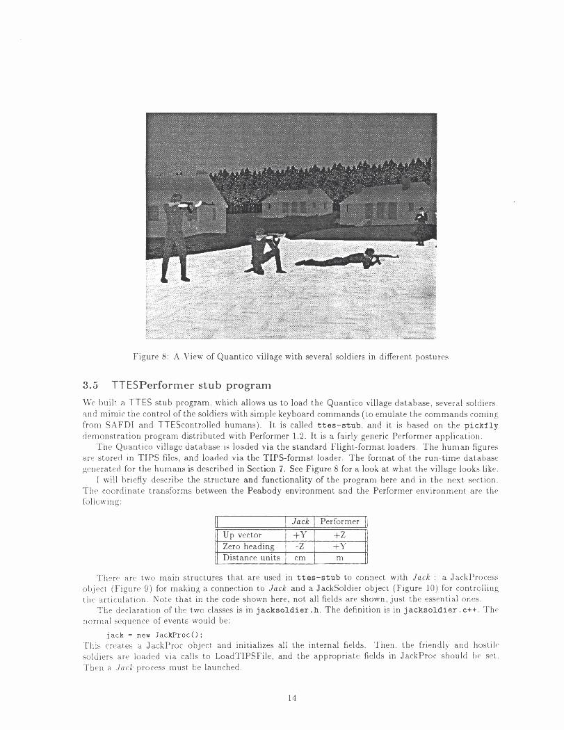
Figure 8: A View of Quantico village with several soldiers in different postures
3.5 TTESPerformer stub program
We built a TTES stub program, which allows us to load the Quantico village database, several soldiers, and mimic the control of the soldiers with simple keyboard commands (to emulate the commands coming from SAFDI and TTEScontrolled humans). It is called ttes-stub, and it is based on the pickf ly demonstration program distributed with Performer 1.2. It is a fairly generic Performer application.
The Quantico village database is loaded via the standard Flighb-format loaders. The human figures are stored in TIPS files, and loaded via the TIPS-format loader. The format of the run-time database generated for the humans is described in Section 7. See Figure 8 for a look at, what the village looks like.
I will briefly describe the structure and functionality of the program here and in the next section. The coordinate transforms between the Peabody environment and the Performer environment are the following:
II - ~~ I Jack I Performer I )
u p vector I +Y I +Z II 1 Zero heading I -Z I +Y 1 - , 1 Distance units I cm I m 1
There are two main structures that are used in ttes-stub to connect with J a c k : a JackProcess object (Figure 9 ) for making a connection to Jack and a Jacksoldier object (Figure 10) for controlling t l ~ e articulation. Note that in the code shown here, not all fields are shown, just the essential ones.
The declaration of the two classes is in jacksoldier .h . The definition is in jacksoldier. c++. Th? normal sequence of events would be:
jack = new JackProcO: This creates a JackProc object and initializes all the internal fields. Then. the friendly and hostile soldiers are loaded via calls to LoadTIPSFile. and the appropriate fields in JackProc should be set. Tllen a Jock process must be launched.

c l a s s JackProc { pub1 i c :
pfGroup *host i lesold ierc lone; // t h e s o l d i e r group f o r cloning pfGroup *fr iendlysoldierc lone; // t he s o l d i e r group f o r cloning
JackUpdateTable *updatetable; i n t n j o i n t s ; i n t n f i g s ; Jo in t Inf o jo in t s in f o [MAXJOINTS] ; FigureInf o f igs inf o [MAXIIGURES] ;
i n t readsocket; / / t he f d were reading from i n t writesocket; / / t he f d were v r i t i n g t o i n t connected; // a r e ve connected yet? i n t jackready; / / is jack ready yet? i n t q u i t t i n g ; // everything s tops ... JackSoldier *table[JACK-MAXSOLDIERS] ; // a t a b l e of s o l d i e r s i n t t a b l e s i z e ; / / how many a r e in t h e r e
JackProc 0 ; v i r t u a l i n t s end( in t token, int s i z e , void *jpk) ; v i r t u a l i n t launchcchar *host , char *remotehost, char *exe, char *da tad i r ) ; v i r t u a l i n t r ece ive (char *message) ; v i r t u a l i n t in it socket connection^) ; v i r t u a l i n t start (char *soldierpref ix) ; v i r t u a l i n t q u i t 0 ; f r i e n d void JackSocketReader(JackProc s j p ) ; f r i e n d c l a s s JackSoldier;
1 ;
ex te rn JackProc * jack; // t he jack process mapper
Figure 9: Jackprocess

c l a s s JackSold ie r { p u b l i c :
i n t soldiernum; / / f o r i n t e r n a l r e f e r e n c e JackProc * j p ; // t h e Jack process c o n t r o l l i n g t h i s s o l d i e r pfGroup * s o l d i e r ; / / t h e Performer c lone pf DCS * j o i n t p t r s CMAXJOINTSI ; pf DCS *f i g p t r s [MAX-FIGURES] ;
i n t s f l a g ; / / is t h e r e something i n t h e socke t b u f f e r ? i n t b u f f e r ; / / consumer b u f f e r t o u s e . . . JackPackl buf [21 ; / / j ack update packe t , double b u f f e r i n t buf s i z e [2] ; / / s i z e of each b u f f e r
JackSold ie r (pf Group *clone, JackProc t j p ) ; v i r t u a l i n t receive(JackPack1 * j p k , i n t s i z e ) ; // f i l l a b u f f e r v i r t u a l i n t u p d a t e ( ) ; / / update t h e Performer t r e e of t h i s s o l d i e r // upda te t h e Jack s i d e of t h i s s o l d i e r v i r t u a l i n t r e q u e s t ( i n t appear , i n t veapon, f l o a t ve loc i ty [3] ,
f l o a t head ing , f l o a t pos i t ion[3] , i n t immediate) ; // f r i e n d l i e s f r i e n d vo id JackSocketReader(JacbProc * j p ) ;
I ;
Figure 10: JackSold ie r

jack->launch(<host>, <remotehost>, <exe>, <data directory>); where <host> and <remotehost> are the machine names for the local machine and the machine Jack should run on (they can be the same, of course). The <exe> is the name of the Jack executable, in our case jack-ntsc-g, and <data directory> is the startup directory of Jack (where all the data files are). Jack is launched via a call to rsh. After Jack is launched, we establish the two sockets:
j ack- ini it socket connection^) ;
The above command opens one read and one write socket to Jack ( J a c k will be waiting for these connections). It also sproc()'s a process to read the incoming packets from Jack . Once the sockets are established, we can communicate with Jack . We send the startup commands to Jack via:
jack->start ("soldierlou") ; which just sends a JCL command to Jack read3 ile("jack-ttes-soldierlow. jcl"). This start. Jack initializing, which may take a while. Before sending any updates to Jnck you have t o wait r l l l t ~ l
J a c k is ready. This is signaled when the jack->jackready flag is set (usually takes about. 30-40 seco~rcl- for J a c k to get ready).
while ( 1 ) { i f (jack-> jackready)
break; s leep(1) ;
I
Once J a c k is ready, we can start adding soldiers, and receiving updates from Jack . For each soldier. fir.<[ you create a new soldier:
JackSoldier *newsoldier = new JackSoldier(jack->hostilesoldierclone, jack); where the first parameter is a Performer tree to clone for the soldier, and the second is the jack proccw pointer. An example implementation of the use of JackSoldier is in the file simsoldier. c++, which 11a. a sample class called SimSoldier, which implements a kind of control for a soldier in the I'erforrllcxr environment, along with simple simulations (soldiers that walk in squares and circles). Once a soldirr 15
created, you can send updates to Jack via:
newsoldier->request(<posture>, <weapon>, <velocity>, <heading>, <posi t ion>); This sends the appropriate information to Jack so it can decide which set of joint angles (frame w i t l l l l r
a bound channelset) to playback.
3.6 Start-up in Jack
Jock is launched from within the TTES process via a call that looks like:
r s h <remotehost> (unsetenv REMOTEHOST; setenv DISPLAY :O; jack-ntsc-g -W 9,600,500,1000 -M 9,600,450,480 -A 9,350,80,10,00urier7 -E open-ttessockets(<host>) -E changedirectory(<directory>)
which does a remote shell (so your .rhosts file should contain <remotehost> if it's different than the local) to launch Jack . The command arguments are: -W: this sets the window location: -hl: srts message window location; -E: execute the command.
The first thing Jackdoes is open the read and write sockets to TTES. This is done via the o p e n - t t e s s o c k e t s (<has
call. J a c k acts as the server for the connection, so it blocks until TTES requests the sockets. The second command. changedirectory (<directory>) will set the default directory to where the TTESrelat ed data files are (for J a c k ) . This allows you to keep Jack and its data files in a separate tree from the rest of TTES.
Once the sockets are open. TTES will send the command read2 ile(" jack-ttes-soldierlow. j c l " ) \vhich will force Jack to begin the initializing sequence. This file is below:

1 read3 ile("jack-ttes-soldierlow. env") ; 2 createsoldierstate("s0" ,"Di21)", "AK-47-0") ; 3 createsoldierstate ("sl" ,"Di2J1', "AK-47-1") ;
createsoldierstate("s9" ,"Di29", "AK-47-9") ; set-channelsetparameters ("no") ; set-ttes~eportinterval(lO.OO) ; set-ttesheading-offest(256.00,0.00,256.00); s e t - t t e s s o l d i e r - t h r o t t l e (0.04) ; set~ttes1e~ortinterva1(30.00) ;
s t a r t ~ t t e s s o c k e ~ s i m u l a t i o n ~ ) ; disablegraphics 0 ;
The first, thing done (line 1 ) is to load the environment file containir~g tilt, 1 0 soltiit,r/gur~ fig~rrc pairs. Lines 2-10 create the t,en soldzer states (structures that hold all statt' info for 1 1 1 ~ ~ holtlic,rj I or.
example, createsoldierstate("s0" , "Di2_0" , "AK-47-0") creates soldier " S O " . f ron~ I I)l.fig figtrr, Di2-0 and gun AK-47-0. The first soldier state create triggers the loading of all the post urt. grap11 f i l , ~ . ~ and associated channelset files. Also, the channels are bound to the soldiers at this point. Linc 11 sets
the playback of the channelset t o real-time (i.e. frame skipping). Line 12 t,ells J a c k to report st.atus ever>- 10 seconds, t o the shell. You can set this to a higher value to remove the messages that appear. I,inc 13 sets the heading offsets associated with the posture transitions, walking. and crawling channelsc~~!- respectively. This was necessary, as the channelsets were recorded before we had the int.erface ~ ' o r k r ~ ~ g . and before we realized we had a bad offset in there! (it was easier to add this command than t.o re-rt.cortl all the channelsets). Line 14 sets a "throttle" value, in seconds. This actually slo\vs t.he rate of upd;ltc packets sent to TTES. This was necessary, as Jack running on its own processor can send out ahout l i )( i(~
updates a second, for 10 soldiers, and the max we'll need for 10 is about 300. This value. set at 0.0.1 seconds, or about 1/30th of a second, will stop Jack from sending out updates for the same soldlcr a1
greater than the inverse of the number (e.g. 1/30 means don't send more than 30 updat,es per sccor~tl\ If your image generator is never going to go over 15Hz, set this value t o 1/15, or about. ,065. I t sa\.cx.<
on net traffic. Line 16 sends the "I'm ready!" message to TTES so it can proceed with the simulatlo~r And finally, line 17 shuts off J a c k graphics. J a c k will not redraw its windows, or spend any tilric doin: anything graphical. At this point, J a c k is ready to receive updates from TTES and send data back.
3.7 Motion Playback in Jack and TTES
Once the simulation is set up, TTES sends requests to J a c k (via JackSo1dier::request.). and receives J O I I I I angle packets (via JackSo1dier::receive). The format of the packets going from TTES to J a c k is s11on.11 in Figure 11.
This is essentially the key DIS parameters for the soldier. The values are in Performer coord~rlatc~s. and are transformed in J a c k when they arrive. Currently, heading and position should he sent,, but tl~c. are not reflected back in the update packets sent to TTES. This is by design, as TTES ~van t s to s~vt
heading and position itself. Position is of the feet (i.e. ground level). The pseudo-code for t l ~ r nlai~l soldier controller in Jack (which is run every iteration of the J a c k main loop, for each soldier) is S ~ I O \ \ . I I
in Figure 12. The updat.e packets are sent out of J a c k from within the motion controllers (which loosely corrc,-
spond t o the "continue ..." statements in the above code; the motion controllers actually are running 'concurrently', as SimulationFunctions in J a c k ) . There are three different motion controllers: posturr.. \valking/running. and crawling. Each one's job is to pick the correct frame from within a bound clia~l- nelset.. and t.his frame is formatted and sent, to TTES as an update packet.
T h e format for joint angle update packets from J a c k t o TTES look like:

#define JACKTTESDEAD 1 #define JACKTTESVPRIGHT 2 #def i n e JACKTTESXNEEL 3 #def ine JACKTTESPRONE 4 #define JACKTTESYEAPONSTOYED 0 #define JACKTTESMAPONDEPLOYED 1
s t r u c t JackPackIn { i n t so ld ier index ; // same on Jack and TTES s i d e [O . .9] i n t appearance; / / one of above (JACKTTES-*) [1,7,3,4] i n t weaponstate; / / one of above (JACKTTES_WEAPON+) [O, 11 f l o a t ve loc i ty C31 ; / / i n meters/second f l o a t heading; / / i n degrees f l o a t positionC31; / / i n meters i n t immediate; / / do we want t h i s now? "snap to"
1 ;
Figure 11: TTES Packets
\\'hen the TIPS file is loaded into the Performer runtime database, the loader writes out a file of articulation parameters, and this information is used to build an u p d a t e t a b l e , which in turn is used to interpret the update packet shown above. Both J a c k and TTES use the same update table. Each entry in the table contains an index, an object name (for either a joint or a figure), and the number of degrees-of-freedom passed for this item. Therefore, the number of dofs per entry varies, usually 1 to 3 for joints, and 16 for figure position (the whole 4x4, but we'll cut this down later to 7: 3 for position, 4 for orientation).
'This design allows us to transmit the minimum amount of information per update, t o keep ~ ~ e t w o r k
soldierindex = [O ,91 size of data array = I S

S o l d i e r s t a t e : : so ld ie rmanager0
{ i f ( a packer h a s arrived) {
copy packet convert from TTES to Jack coordinates
1 compute v e l o c i t y compute heading i f (soldier is currently transitioning) {
grab new heading continue posture transition r e t u r n
1 i f ( a packet has arrived and
(posture is different o r weapon is different) ) { i f (soldier is locomoting)
cancel the step select the goal posture node from posture graph start a new posture change (from current to goal) r e t u r n
1 i f ( ( v e l o c i t y > 0) and (soldier is PRONE)) {
continue crawling r e t u r n
1 i f ( ( v e l o c i t y > 0) and (soldier is STANDING)) {
continue either walking or running r e t u r n
1 i f (no motion or posture change, but a heading change) {
send the last update packet with heading change 1
Figure 12: S o l d i e r manager's main loop

traffic at a minimum (a complete low-res soldier update is about 440 bytes), and affords us the ability to take advantage of frame-to-frame coherence in a motion, and not transmit data that's not changing (although we haven't tried that yet). The first incarnation of the J a c k T T E S interface was implemented via shared memory. We passed the entire joint transform (16 floats) for each joint. While this has the advantage of speed, it has the greater disadvantage that J a c k needs to run on the same machine, and will not scale well to many soldiers.
4 Running the Demo
To run the demonstration executable, you should first unload the tape (tar format) into a directory, say /usr/demos/ttes. For convenience, define an environment variable to point here. for example,
% setenv TTES /usr/demos/ttes
The files will be in directories according to the organization in Section 6 . Your environment shoulti contain the necessary settings for running Jack .
4.1 Starting things up
To start the demo, run the following commands3:
The parameters are: -W: window size for the program; -H: host to run Jack on (can be local): - J . J a c k executable; -I: directory to run J a c k in; -F: Performer data file path; urban.flt is the Quantico village database. Once the program starts, J a c k will be launched (you should see its screen come up) ttes-stub will load the village database, and finally show you a bird's eye view of the whole area. 1 . o ~ should pick the "SOLDIER CAM" view from the "View" menu on the left side of the window. Tills places you on a tethered camera, attached to soldier 0, who is standing in the middle of the village Soldier 1 is walking in a square, and soldier 2 is walking in a circle.
4.2 Keyboard commands
The ttes-stub program is derived from pickfly, so it has ail the features of that program (see Performer 1.2 documentation). In addition, the following keyboard commands are added (these are to exercise the features of moving the soldier figures around) (Note: the current soldier starts at 0, and all commands are relative to the current soldier):
"11 executables were compiled for Irix 4.0.5

1 I Set posture to DEAD on current. soldier. 2 I Set ~ o s t u r e t o STANDING on current soldier. 1 3 4
Set posture to KNEELING on current soldier. Set posture to PRONE on current soldier.
5 G
n or Pu'
Set weapon state to DEPLOYED on current soldier. Set weapon state to FIRING on current soldier. Next soldier. Set current soldier to next soldier (i.e. if current
p or P a
soldier is 1 , sets current soldier to 2.) Previous soldier. Add another soldier. This creates a new soldier, standing near the
A
-
low office building. A maximum of 10 soldiers (0-9) can exist. Add a Jackcontrolled soldier. This adds a new soldier tha t is con-
1 i or I i or J
u or U d or D
Rotate tethered camera $10 degrees about current soldier. Rotate tethered camera -10 degrees about current soldier.
o or 0 Left. Right Arrows
4.3 Taking a walk in the field ...
trolled via Jack (reactive behaviors). This is experimental for now. Move the tethered camera AWAY from soldier by $5 meters. Move the tethered camera TOWARDS the soldier bv -5 meters.
u
Move tethered camera to OVERHEAD view on current soldier. Change heading -10 or $10 degrees on current soldier. - ., - -
Up, Down Arrows 1 Change velocity $0.5 or -0.5 meters/second on current soldier. 7 I Prints a list of keyboard commands to the stdout (console).
When you first start up, you are looking a t soldier 0. Start him walking slowly by pressing tlir [Up Arrow] key. Change his heading so he walks towards the open fields by pressing [Left Arrow]. You can swing around him by holding the [i] or Ij] keys. Take a look a t him from above by pressing [o]. Press [i] again until you are looking a t him from the side. Now increase velocity with the IUp] arrow. When he exceeds 3 meters/second he'll s tart t o run. The drop him back to zero by pressing [Down Arrow]. If you press [Down Arrow] again, he'll walk backwards. Bring him to a stop again. Now try pressing the keys [2], [3] and [4] t o see him adopt various postures. Also use [5] and [6] t o see him shoulder his rifle. If you press [I] he dies . . .p ress [2] to resuscitate him. Press [4] to make him go PRONE. Then give a little forward velocity, and he CRAWLS forward. Once you get the hang of i t , try taking a couple of soldiers out into the field, using [n] and [p] t o toggle between them. You can drop the soldier-tethered camera and just drive or fly around by choosing "Fly" or "Drive" from the ''\'iewW menu.
L
4.4 Looking a t things in Jack ... IVhile the simulation is going on in the Performer program, Jack is providing motion data , reacting to the changing states of the soldiers. You won't see anything happening in Jack as the graphlcs are disabled. If you enable graphics, you'll see 10 soldiers standing a t the origin, and several may be walking in place, according to their state. However, what's going on inside Jack is the same as in Performer. We can see that by doing the following (while you have t tes-stub up and running). G o to the station Jack IS running on. Jack will respond to your keyboard commands.
Enter the command r e a d 2 i le("jack-t tes-terrain. j c l J ' ) This will turn off soldiers 5-9, and set Jack to show the soldiers in their correct global positions in space (1-to-1 with Performer). I t also will read t,lle file urban-terrain. env, which is the Jack equivalent to the urban. f lt file4. You can
41f Jack doesn't load the file correctly, load i t manually from the directory you installed it into. $TTES/jack-terraidurban-terrain.env$
do change-view to move the camera around a bit, but you should see things just as they are on the Performer side of things.
5 Conclusions & Future Work
We have built and demonstrated a system for off-line production of motion sequences, together wit11 a method for putting those motion sequences together (posture graphs and locomotion control) for real- time playback t o a remote image generator. Also, we have created a systen~ for animating the I lun~ar~ motion associated with what can be expressed about a human figure in the DIS protocol.
There are many areas in which this work could advance or be improved. Some of our suggrstior~> f < ) r imn1ediat.e additional work are listed below:
Posture Transitioning
As the number of possible states for the human increases, the post urc' gri~plrs , ~ l i c ~ u l t l I I ! r r l l l : ~ , - !
with a more procedural approach t o changing posture. For t hc, apl)licat Ions t t o ~ l ; ~ ! O I I c.\!rr.c 111
workstations, the current technique balances performance and rralisnl SAiVC'I'SI) woul~l Ill ,!
t o control the human figures (both hostile synthetics and friendly avatars) with t hr- sanlc, con1 rol scheme, based on sensor values from locations on the human figurt. \I-c will t)c ~rivcst~gatirig 11115
in the near term.
Production of posture transitions:
In general, the process went smoothly, but there were several aspects that can be iniljrovt~d 1111011
The video that was supplied t o us showed the soldier only from one viewing a~lgl(. I t K O I I I ~ I have been better to show the same movement from several different views (ultimatt-I> fro^^^ the three orthogonal axes views, as they are used in a rotoscoping system). As i t w i ~ s . i t \\.;I-
sometimes hard to tell where exactly a given limb would end up (e.g. it was blocl;t~cl fro^^^ view by another body part) .
- Jack< constraint system was very helpful in roughing out the movement,. Yet, for t h ~ s sl1111i- lation we wanted to achieve a movement that looks as fluent as possible. This provc,tl to 1 1 1
somewhat difficult under Jack. What would be desirable, would be a facility to " f in t ) - tu~~~ "
a motion better. Similarly, the algorithm used to drive the inverse kinematics sonlet I I I I ~ ~ ~
produced unpredictable results when different goals (motions) affected the same k i11~111 i i t I ( .
chain.
- As an ultimate improvement for this process would be a system that could create t , l i ~ I I I O I loll.< directly from the video, without the use of any animators (automatic rotoscoping), or s a i ~ ~ p l t . the motion using a body suit, or a set of sensors (e.g. Flock Of Birds) and recreak t l~r, mot 1011
using this data . We think this is the most promising solution.
Generalize the cyclic posture changes
The cyclic posture transition state machines are currently hard-coded for each cycle ( w a l k ~ r ~ g . running, and crawling). The static posture transition state machine is general and data-drivr-11 We should generalize the cyclical state machines, so they can be driven completely by data filcs (like the static postures). The key t o doing this will be the specification of conditionals on w11icI1
states change. These could be specified in cyclic posture graph da ta files as LISP expressions. ant1 interpreted on-the-fly. during runtime.
Some bells and whistles
During the production of one of our posture transitions, a glitch was introduced in ont, of t 1 1 1
transitions that caused the soldier to jerk backwards a bit when a transit~on started Tht. solcl~c~r.

working with TTES saw this and liked it very much, thinking we were animating kickback from a firing rifle. We could formalize this a bit, and look a t the event-type information in the DIS stream (weapon fire, explosions, etc) and create small (2-5 frame) sequences of motion to give the illusion the soldier is reacting to the event. This could prove a very inexpensive way of increasing the illusion of reality.
Intelligent, Reactive Friendly soldiers:
Another interesting extension of using J a c k for TTES will be the incorporation of some work by Becket and Reich. which endows the soldier figures with the following abilities. These could used t o generate Jack-controlled soldiers to easily populate the world, with a simple prograniniat~c control of their higher-level behaviors.
I n f r a r e d : A simple infrared model is available. Each figure or segment in an environment call I I V tagged with a "heat" value between zero and one. A mode exists to display the environn~c,nt using these heat values, interpolating from black to red, instead of the normal visible.-1i~;llr colors.
A t t r a c t i o n : Attraction is used to guide an agent towards an object, or agent, towards a global location, or towards a location relative to an object, or another agent. For exan~ple , attraction might be used to have a friendly soldier try t o stay 10 feet away, 20 degrees to the right of another agent as tha t agent moves around in the environment.
Avo idance : Avoidance is used to keep an agent away from specific objects, locations, or other agents.
Terrain Sensor : Terrain sensors detect the types of terrain surrounding an agent. A t.erra111 sensor may be used to have an agent avoid certain types of terrain such as water, or to kcep an agent on a path or road.
H o s t i l e Fie ld-of-View Sensor : The hostile field-of-view sensor may be used to have an agent avoid the line of sight of one or more hostiles.
Enlbed motion control in Performer
The current implementation of the motion controllers in J a c k rely mostly on stored motions. Therefore, it would be quite possible t o remove them from Jack and embed directly in Performer Then , the J a c k process would not need to be run during a TTES session, increasing performance of the system overall. If we use inverse-kinematics and constraints on sensor da ta (as is likely i l l
~ I I P near-term), this would be more difficult, as it would entail embedding tha t part of Jack in Performer. Eventually, though, this is the goal.
6 Appendix A: Data and Code Files
This is the directory structure on the tar tape. Note: files with .Z suffix are compressed and should hc uncompressed before using. Also, there are several symbolic links to cut down on duplications of files.
./movies/* .mv SGI movieplayer (Irix 5.2) files of posture transitions (as supplied by NAWCTSD). Thc video was broken up into 3 movie files.
./share/motions/* Motion files live here. Each motion has an associated frame 0 * . env file and a *motions. env file. In all motion files, the regular (soldier-cam.fig) soldier is named soldier, t h e gun is named AIi-47-color2 (don't ask) , and the Dl is called Di. T h e nomenclature for files is:
st = standing
k = kneeling

pr = prone
dead = dead
fire = firing
stow = stowed (actually deployed)
For example the motions from standing stowed t o kneeling firing are ststowakf i r e . env
. /share/motions~chsets/* The channelsets, both for regular soldier, and low-res DI. f i g . The nomen- clature is similar to that of the motion files, with the additional l o w specifying the low-res soldier. and . chse t . marking this as a channelset file. Several ,ICL files here are also used t o automate the motion->channelset and slaving procedures.
. / ~ h a r e / ~ e r f - terrain/* These are the Flight-format geometry files for the Quantico village environ- ment. The main file is urban. f lt
. / share / jack- ter ra in /* These are the same Quantico village environment, but converted t o Peahody format. The main file is urban. env (unfortunately, no texture maps).
. /share/data/* These are Jack data files, defining the various figures used, psurfs, and texture maps.
. /src/common These are the shared files between Jack and TTES.
j ackpack. h Format for packets going from TTES to Jack and back
update table . c++ Both sides use the updatetable object, which defines format of packets flowing from Jack to TTES.
. / s r c / j ack / These are the files that make up Jack. These files were the only additional or changed files above and beyond the 5.8 libraries.
Motioncontrol. h The locomotion/crawling motion control object.
channelset . c++ Channelset CMDs and definition.
channelse t . h Channelset declarations.
jack-ntsc-g The Jack executable (symbolic links point here)
jack-channel. c++, cont ro l input2 motion Slightly modified from the 5.8 libraries. These files don't have much t o do with the TTES functionality.
j ackmotioncontrol . c++ Definition of Motioncontrol (locomotion) controller.
j acksock . c++ Socket communications process, and CMDs for all TTES related commands.
menu. c++ Main menu definition for Jack.
pea-parse . c++ , pea-parse. y Modified Peabody parser to handle indexed fields in constructs
peastuf f . c++ Parser callouts for handling channelset and sharedchannel fields and constructs
pgraph. c++ Definition of PostureGraph class
pos tures . c++ Definition of BoundPostureGrapph, and CMDs for all posture commands.
pos tures . h Declaration of Posture* classes and functions.
setmot ion . c++ Definition of the channelset motion.
setmoti0n.h Declaration of the new SetMotion type.
sharedchannel. c++ Definition of the new SharedChannel type (sub-class of Channel), and two sub-classes: SharedFigureChannel and SharedJointChannel.

sharedchannel . h Declaration of above.
s l a v e . c++ Slaving CMDs and functions.
s o l d i e r . c++ Definition of Soldierstate class, which wraps up all the other things, and manages interface with TTES.
s o l d i e r . h Declaration of above.
s p i t t e r . c++ The spitter, creates .tips files
t t es -c rawl . c++ State machine for crawling.
t t e s g l o b a l . c++ Global coordinates computation for soldiers
t t e s l o c o . c++ State niachine for walking and running
t t es - tes tcmds . c++ Testing commands for use when no TTES process connected.
OPT/ttes-stub. OPT Actual executable file
cmdline frame gui keybd main object picking These are all just slight modifications from the pickfly original, as distributed with Performer 1.2.
j a ckso ld i e r . c++ Definition of the JackProc and JackSoldier classes.
j a ckso ld i e r . h Declarations for above
j ackupdate. c++ Some sample functions, which call the appropriate functions within other nod- ules, t,o start up J a c k and create soldiers. You would have something like this in your own system.
p f t i p s . c++ The TIPS loader
pf t i p s . h Declarations for above.
pickf l y . c Main routines for the interface.
socke t . c++ Simple routines for making a socket connection with J a c k .
so ld i e r s im . c++ A sample implementation of a simulated soldier, with calls into the main func- tionality of JackSoldier. Use as a template for your own.
. / s r c / t i p s l l / This is the modified TIPS loader for Performer 1.1. See the description in Section 7.3.
/demo/jack/ Files for J a c k when running the demo. This is the directory in which J a c k should execute during the demo. The subdirectory . / demo/ jack /chse t s holds the pre-computed motions.
. /demo/perf ormer/ This is where you start up the demo.
7 Appendix: TIPS file format and Performer Loader
Iloughly, a . t i p s file is a record of the information obtained in a traversal of the Peabody environ- 11lent. For each figure in the environment (except the camera) a depth-first traversal of the figure's sit.es is performed, starting a t the root site and following joint connections bet,ween sites. Use of this intermediate-style format avoids calling the Peabody parser from within the Performer applicat.ion; we found development to be faster without the added complexity of modules linked with both the (extell- s ~ v e ) Jack 5.8 libraries and the Performer 1.1 or 1.2 libraries. I t is for similar reasons of speed and convenience of development and debugging that we chose a human-readable plain-text format. You can crt3atc a . t i p s file from within J a c k be executing the command s p i t ( " f i l e . t i p s " ) which will dunip everything in the environment. (except cameras) into f i l e . t i p s .

7.1 TIPS file format specification
The following is an informal description of the structure of a .tips file. Newlines in each part of the description correspond to newlines in the file. Entries in the file are generally strings, integers, or floating point values, and the exact meaning of constructs in the description should be clear from the example .tips file in the nest section.
[.TIPS FILE] ::= [number of figures] [COMMENT] [FIGURE DESCRIPTION] *repeated [number of figures] times*
[FIGURE DESCRIPTION] ::= [COM hlEKT] [figure name] [COhIhIENT] [figure filename] [COMMENT] [4s4 global position transform] [COhIMENT] [4x4 root site inverse transform] [SEGMENT DESCRIPTION] *for the figure's root segment*
[SEGMENT DESCRIPTION] ::= [PSURF FLAG] [COMMENT] [GEOMETRY] *only if [PSURF FLAG] = I* [number of sites] [COMMENT] [SITE] *repeated [number of sites] times*
[SITE] ::= [number of joints] [COMMENT] [COMMENT] [site name] [COMMENT] [4x4 site transform matrix] [JOINT] 'repeated [number of joints] times*
[.lOINT] ::= [ROOTJOINT FLAG] [COMMENT] [COhIhIENT] [4x4 joint transform matrix] [REVERSE JOINT FLAG] [COMMENT] [number of DOFS] [COMMENT] [DOF] *repeated [number of DOFS] times* [COMMENT] boint name] -
[COMMENT] [OTHERSITE name] [COMMENT] [4x4 inverse of OTHERSITE transform] [SEGMENT DESCRIPTION; *for segment at other end of joint*
[DOF] ::=

[DOF type] [COMMEIL'T]
[GEOMETRY] ::= [number of attributes] [COMMENT] [ATTRIBUTE] *repeated [number of attributes] times* [number of nodes] [COMMENT] [node coordinate 3-vector] *repeated [number of nodes] times* [number of faces] [COMMENT] [FACE] "repeated [number of faces] times*
[ATTRIBVTE] :.= [ambient color 3-vector] [diffuse color 3-vector] [specular color 3-vector] [TEXTITRE FLAG] [COhIhIENT] [texture filename] *only if [TEXTGRE FLAG] = l *
[FACE] ::= [attribute index number] [COMMENT] [number of vertices] [COMMENT] [face color RGB vector] [VERTEX] *repeated [number of vertices] times*
[\:ERTEX] ::=
[node index number] [texture coordinate 2-vector] *only if [TEXTURE FLAG] = l*
[COhlMENT] ::= any string of characters terminated by a new line
7.2 Example . t i p s file
The following .tips file (reproduced verbatim) represents a Peabody environment which contains a single unit cube as its only figure:
1 f i g u r e s FIGURE #O cube FIGURE #O cube. f i g Global p o s i t i o n m a t r i x 1.000000 0.000000 0.000000 0.000000 0.000000 1.000000 0.000000 0.000000 0.000000 0.000000 1.000000 0.000000 0.000000 0.000000 0.000000 1.000000 Root s i t e i n v e r s e mat r ix 1.000000 0.000000 0.000000 0.000000 0.000000 1.000000 0.000000 0.000000 0.000000 0.000000 1.000000 0.000000
0.000000 0.000000 0.000000 1.000000
I (psur f f l a g )

1 (# attributes) 0.173333 0.125490 0.173333 0.693333 0.501961 0.693333 0.000000 0.000000 0.000000 0 (texture flag) 8 total nodes 0.000000 0.000000 0.000000 0.000000 0.000000 1.000000 1.000000 0.000000 1.000000 1.000000 0.000000 0.000000 0.000000 -1.000000 0.000000 0.000000 -1.000000 1.000000 1.000000 -1.000000 1.000000 1.000000 -1.000000 0.000000 6 faces 0 attribnum 4 vertices 0.000000 0.000000 0.000000 0 I 2 3 0 attribnum 4 vertices 0.000000 0.000000 0.000000 0 3 7 4 0 attribnum 4 vertices 0,000000 0.000000 0.000000
2 6 7 3 0 attribnum 4 vertices 0,000000 0.000000 0.000000 0 4
5 1
0 attribnum 4 vertices 0.000000 0.000000 0.000000 4 7 6 5 0 attribnum

4 v e r t i c e s 0.000000 0.000000 0.000000
1 5 6
2
1 s i t e s 0 j o i n t s SITE base S i t e 1 matrix 1.000000 0.000000 0.000000 0.000000 0.000000 1.000000 0.000000 0.000000
0.000000 0.000000 1.000000 0.000000
0.000000 0.000000 0.005000 1.000000
7.3 Alternate . t i p s format
An alternate format was developed to handle a last-minute change requirecl 1))- 1 1 1 ~ TTES pro.lc,ct. ~ ~ a i i ~ r ~ l ? that the Performer . t i p s format loader run under Performer 1.1 rather tllail Prrforii~er 1 .2 TI]<, kl.! difference between the two versions with respect to the loader is that Perfornler 1 .1 lacks t l ~ i y ~ ) f r ~ U t i ~ l t i c , r
object of 1.2, which performs automatic generation of efficiently-meshed triangle strip GeoSt,ts ( ~ ~ Y I I I I -
etry objects) and their associated GeoStates (attribute objects) from arbitrary polygon a11t1 at t r ~ l > ~ ~ r 1 ,
information. Our solution was to use the 1.2 pfuBuilder routines to generate GeoSt,ates and meshrtl gr7011rc,tr>
whicll were then written into a slightly modified . t i p s file intended to be read in a Perforriic-s I 1
environment. The only change, therefore, is in the encoding of geometric information:
[GEORJETRY] ::= [number of attributes] [COMMENT] [ATTRIBUTE] *repeated [number of attributes] times* [GEOSET] *repeated one or more times* eiidgeosets
[GEOSET] ::= geoset [attribute index number] [COMMENT] [number of triangle strips] [COMMENT] [length of strip] *repeated [number of triangle strips] times* [indexing mode] [IrERTEX1] or [VERTEXP] *repeated once for each vertex* [color binding] [COLOR11 or [COLOR21 'depending upon [color binding]* [normal binding] [NORMAL11 or [NORMAL21 *depending upon [normal binding]' [text,ure binding] [TEXCOORD] *only if [texture binding] = PFGS-PER-VERTEX*
[i7ERTEX 11 ::= [vert,ex index number] [vertex 3-vector] *used if [indexing mode] = indexed*

[VERTEX21 ::= [vertex 3-vect,or] *used if [indexing mode] = not indexed*
[COLOR11 ::= [color 4-vector] *repeated once for each vertex*
[COLOR21 ::= [color 4-vector]
[NORhIALl] ::= [surface normal 3-vector] *repeated once for each vert,es*
[IVORhlAL2] ::= [surface norlnal 3-vector]
[TEXCOORD] ::= [texture coordinate 2-vector] *repeated once for each vertcs*
For obvious reasons, this encoding is very similar in structure to that ilsecl W I t 11111 a Pt3rforr111 I
pfGeoSet. [COLOR11 and [NORMAL11 are used when "PFGS-PER-I'ERTES" attribute, I ) I I I~I I I : : I -
in effect (indicating a value for each vertex) and [COLOR21 and [NORRIIAL~] for "PFGS-O\'EI< :\ [,I.' attribute binding (indicating a single shared value for all the vertices).
7.4 Runtime database structure
Performer 1 .1 and 1.2 are both limited to a maximum scene graph depth5 of 32. For tllis rc,ilsoil n . t
use just one pfDCS node for each joint in the Peabody hierarchy. Since a Peabody joint c o ~ l s l s t ~ of three transformations (site 1, joint angle, and site 2 inverse), two matrix multiplications are requlred 1 0
compute each new DCS value. This single-DCS approach was chosen because the alternative. t , rcal i~r l~ up the figure hierarchy into several smaller pieces, would entail unnecessary complexity and additrorl;tl bookkeeping. The matrix multiplications must be done a t some point anyway; nothing is lost. by I I I ~ ~ I I I ~
them part of the update process. The two site transforms do not change during simulation. so t l ~ r , ! are stored by the Performer application and a t each frame the Jack process need only t,ransfcr t 1 1 t .
updated joint transforms over the socket or shared memory connection, thus minimizing communrcat 1011
bandnidt.h. Even with only one DCS per joint, the Jack 5.8 human approaches the Perforn~er-i~l~l~o>t,t l li111ii. 70 nlinimize its depth we root the human through the waist a t all times.
TTES en t i t i e sGre attached to the top level of the Performer scene graph by the sequence of nocic+ shown in figure 13. The node labeled "Entity Position DCS" allows the human and gun subgraphs to I ) ( % manipulated as a single unit. More specifically, we update the value of this transformation a t each f ran~v to reflect the terrain ground height under the TTES entity. Our geometry being defined such tliat t l l r ,
coordinate origin is located between the human's feet, this is a simple matter of casting a vertical ray ~ n t o the scene and using the intersection point directly t o determine the appropriate translation matr ls . ?'!I(, "Figure DCS" node for a particular figure corresponds to the transformation obtained by rnultipl\lr~g the global position transform of the figure's root site by the inverse of the root site transform. 7 ' 1 1 1 h
informat,ion is also part of the update packet sent by Jack on each frame, mapping figure movenicnts in the Jack environment into the Performer environment. Figure 14 explains the structure of the s c ~ ~ r ~ r ~ subgraph representing a Peabody segment.
5Here we define depth to be the maximum number of pfSCS and pfDCS nodes on any path from the scene graph ro,,t to one of its leaves.
" A n entity in our case consists of two figures: a camouflaged human and a rifle.

Graph
Figure hierarchies, beginning at their respective root sites
... ..-.__. ..... ............................... ....''-
One such subgraph for each ITES friendiyhostile
Figure 13: A TTES Entity in the Performer scene graph
Segment pfGroup
Only present i f segment :, Hierarchies tor attached segments / has geometry (segment pfGroup nodes) ,.'
--.___ -..__....__..---- ._... One such subgnph for the joints of
each site on the original segment
Figure 14: The subgraph corresponding to a Peabody segment

Finally, the "Joint DCS" nodes are set according to the three composed transformations mentioned earlier. Changing the values stored at these DCS nodes is tlie main component of the update process, and hence the Performer application also maintains an indexed array of pointers, one to each of the "Joint DCS" nodes in the graph, for fast access.