IWAKI Magnetic Drive Pump MX-70/-100 (Asia Edition) Instruction Manual · 2013-07-05 · Read this...
20
Read this manual before use of product IWAKI Magnetic Drive Pump MX-70/-100 (Asia Edition) Instruction Manual
Transcript of IWAKI Magnetic Drive Pump MX-70/-100 (Asia Edition) Instruction Manual · 2013-07-05 · Read this...

Read this manual before use of product
IWAKI Magnetic Drive PumpMX-70/-100 (Asia Edition)Instruction Manual

Thank you for selecting an Iwaki MX-70/-100 type Magnetic Drive Pump. This instruction manual deals with "Safety Instructions", "Outline", "Installation", "Operation" and "Maintenance" sections.Please read through this instruction manual to ensure the opti-mum performance, safety and service of your pump.
WARNINGNonobservance or misapplication of the contents of “Warning” section could lead to a serious accident which may result in death.
CAUTIONNonobservance or misapplication of the contents of “Caution” section could lead to a personal injury or damage to the product.
Types of SymbolsIndicates a prohibited action or procedure. Inside or near this cir-cle, a concrete and practical image of the activity to be avoided is depicted.
Indicates an important action or procedure which must be per-formed or carried out without fail. Failure to follow the instruc-tions herein can lead to malfunction or damage to the pump.
For the Safe and Correct Handling of the Pump
● "Safety Instruction" section deals with important details about handling of the product. Before use, read this section carefully for the prevention of personal injury or property damage.
● Observe the instructions accompanied with "WARNING" or "CAUTION" in this manual. These instructions are very impor-tant for protecting pump users from dangerous situations.
● The symbols on this instruction manual have the following meanings:
Important Instruction
This instruction manual should be kept on hand by the end user for quick reference.
Contact us or your nearest dealer if you have any questions.
For exportationTechnology related to the use of goods in this instruction manual falls in the category of technology contained in the Foreign Exchange Order Attachment, which includes complementary export control of technology. Please be reminded that export license, which is issued by the Ministry of Economy, Trade, and Industry could be required, when this is exported or provided to someone even in Japan.
Contents
Safety Instructions ··········································································1Outline 1. Unpacking & Inspection ·······································3
2. Operating principle ···············································33. Identification code ················································44. Specification ·························································45. Outer dimensions ··················································56. Performance curves ·············································67. Overview & Label ·················································68. Part names & Structure ········································7
Installation 1. Before installation ·················································92. Installation/Piping/Electrical wiring ················· 11
Operation 1. Before operation ·················································· 14Maintenance 1. Troubleshooting ·················································· 16
2. Maintenance & Inspection ································· 163. Drainage ······························································ 17

- 1 -
Power off
Safety Instructions
Prohibited
Prohibited
Prohibited
No modificationNo dismantlement
Caution
Caution
Wear protectors
WARNING
● Turn off the power. Risk of electrical shock. Dismantling/assembling the pump unit without turn-ing off the power may cause an electrical shock. Before engaging in any maintenance or inspection work, be sure to turn off the pump and related devices.
● Terminate operation. On sensing any abnormal sign, stop opera-tion immediately and inspect/solve prob-lems.
● For specified application only The use of the pump in any application other than those clearly specified may result in injury or damage. Use the pump in a specified condition.
● No dismantlement/modification Do not dismantle/modify the pump. We are not responsible for any accidents or damage due to modification.
● Wear protective clothing. Always wear protective clothing such as safety goggles and protective gloves during pipework or dismantlement.
● Restriction on operator The pump should be handled by a qualified person with a full understanding.
● Specified power only Do not apply any power other than the spec-ified one on the nameplate. Otherwise dam-age, a fire or an electrical shock may result.
● Do not wet the pump. If a liquid spills over electric parts or wires, a fire or electrical shock may result. Install the pump in a place free from liquid spillage.
● Ventilation Poisoning may result when handling a toxic or odorous liquid. Keep good ventilation in your operating site.
● Countermeasure against effluxTake a protective measure against the acci-dental efflux caused by pump or pipe break-age.
● Do not use a damaged pump.Using a damaged pump may lead to an electric leak or shock.
CAUTION
Prohibited
Prohibited

- 2 -
Prohibited
CAUTION CAUTION
Safety Instructions
● Do not place the pump close to water. The pump is not dust-/water-proof construc-tion. The use of the pump in a humid place or a place where the pump can get wet may result in electrical shock or short-circuit.
● Do not run pump dry. If the pump runs without a liquid, the pump is damaged by friction heat.
● Do not damage the power cable. Risk of fire or electrical shock. Do not scratch, modify, or pull the power cable. The cable can also be damaged when it is heated or loaded with a heavy thing.
● EarthingRisk of electrical shock. Always earth the pump.
● Do not pressurize the pump over the maximum discharge pressure.A leak may result from the sealing surface of O ring or the pump fails at worst.
● Install an earth leakage breaker.An electrical failure of the pump may ad-versely affect related devices. Purchase and install an earth leakage breaker separately.
● Power cable is not replaceable. Do not use any damaged power cable for the prevention of a fire or an electrical shock. The cable is not replaceable, so that the whole pump unit needs to be replaced when the cable is damaged.
● Limited operating site and storage Do not install or store the pump in the fol-lowing places where...1. Ambient is beyond the range of 0 - 40°C.2. Under a flammable/corrosive atmos-
phere.● Disposal of the used pump
Dispose of any used or damaged pump in accordance with relevant regulations. Consult a licensed industrial waste products disposing company.
● Static electricity When low electric conductivity liquids such as ultra-pure water and fluor inactive liquid (e.g. FluorinertTM) are handled, static elec-tricity may generate in the pump and may cause static discharge. Take countermeas-ures to remove static electricity.
Caution
Prohibited
Prohibited
Electrical shock
Prohibited
Earthing
Electrical shock

- 3 -
Before use, check the specification, limitation and hazardous nature of the pump.
1. Unpacking & Inspection On unpacking the product, check the following points. If you find any problems, contact your nearest dealer.
1. Check the information on the name-plate such as model, discharge capacity, discharge head and volt-age to see that the product is deliv-ered as per order.
2. Check for transit damage, deformation, and loose bolts.
Outline
Inlet
Outlet
Driven magnetImpeller
Drive magnet
Spindle
2. Operating principleThe MX is a magnetic drive centrifugal pump.The magnetic force between drive and driven magnets rotates the impeller in the pump chamber, where a liquid is transferred from the inlet to outlet.

- 4 -
3. Identification code
MX - 100 V M - 32 a b c d e
a. Series modelGFRPP casing material
b. Pump size70100
c. O ring materialV: FKME: EPDM
d. Inlet/OutletNo code: Tube connectionM : Thread type (G)FL : Flange connection
e. Motor power voltageNo code: 1 phase 100V32 : 3 phases 200/220V
Outline
4. Specification 50/60Hz
Model Max flow(L/min)
Maxhead(m)
Norm flow(m-L/min) Max SG
MotorMass(kg)Power
(V)Rated output(W)
MX-70 90/100 8/11 5.4-50/7.8-50 1.0100
150/180 6.5200 or 220
MX-100 110/125 8.4/11.7 6-70/9-70 1.2100
260/260 8.2200 or 220
ModelTube connection Thread connection Union connection Flange connectionInlet Outlet Inlet Outlet Inlet Outlet Inlet Outlet
MX-70 26mm G1 20mm 25AMX-100 26mm G1 20mm 25A
NOTE:a. Performance data is based on pumping of clear water at
ambient temperature.b. Allowable liquid temperature is 0-80°C (0-55°C for union
connection). Note that the temperature range may change with liquid property. Avoid a precipitous fluctuation of tem-perature even in the liquid temperature range above.
c. The maximum head is a shutoff head. Note that shutoff oper-ation is not allowed, or it may adversely affect a life period.
d. The maximum specific gravity is obtained at the maximum flow and changes with a duty point, room-/liquid-tempera-tures and liquid viscosity.
e. A single-phase capacitor-start induction motor and a 3-phase motor are selectable.
f. See the specification label on the pump for detail info.g. Performance and dimension are subject to change without
prior notice.

- 5 -
5. Outer dimensionsMX-70(M)/-100(M)
Model W H L a b c d e f g i j k
MX-70(M) 130 155 258.5 110 48 40 65 90 53 159.5 7 11 60
MX-100(M) 150 175 319.5 110 51 70 75 100 65 162 9 27 90
MX-70FL/-100FL
Model W H L a b c d e f g h i j k
MX-70FL 130 162 266 110 48 40 65 97 53 167 25A 7 11 60
MX-100FL 150 182 327 110 51 70 75 107 65 169 25A 9 27 90
■ AccessoriesOptional unions are available as a coupling devise. Contact us for detail.
Model Union fitting O ring Union bore(Nominal dia)
MX-70M G1 AS-568-020 20mmMX-100M G1 AS-568-020 20mm
Outline
4-i4-j
gck W
aH
de
bf
L
- 6 -
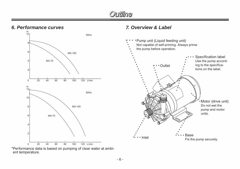
6. Performance curves
* Performance data is based on pumping of clear water at ambi-ent temperature.
Outline
Motor (drive unit)Do not wet the pump and motor units.
7. Overview & Label
InletBaseFix the pump securely.
Specification labelUse the pump accord-ing to the specifica-tions on the label.
Outlet
Pump unit (Liquid feeding unit)Not capable of self-priming. Always prime the pump before operation.
0 20
2
4
6
8
10m
50Hz
MX-70
MX-100
40 60 80 100 120 L/min
0 20
2
4
6
8
12
10
m
60Hz
MX-70
MX-100
40 60 80 100 120 L/min

- 7 -
101 14
12
2
11
9
13
9
5
8
3
15
2
6
1101
14
12
4
10
13
17
11
6
8
5
3
7
2
18
15
9 1
Outline8. Part names & StructureMX-70(M)
No. Part names Q'tyMaterials
MX-70(M) MX-100(M)1 Front casing 1 GFRPP
2MX-70: Bearing 2 PPS -MX-100: Bearing A 1 - PTFE
3 Rear casing 1 GFRPP4 Bearing B 1 - PTFE5 O ring 1 V: FKM E: EPDM6 Impeller 1 CFRPP7 Shroud 1 CFRPP8 Spindle 1 Alumina ceramics
9MX-70: Thrust 2 Alumina ceramics -MX-100: Front thrust ring 1 - Alumina ceramics
MX-100(M)
No. Part names Q'tyMaterials
MX-70(M) MX-100(M)10 Rear thrust ring 1 - Alumina ceramics11 Driven magnet 112 Drive magnet unit 113 Drive magnet 114 Hex. sock set screw 2 Steel15 Hex. head bolt 6 Stainless steel17 Retainer ring 1 - SUS30418 Mouth ring 1 - PTFE101 Motor 1

- 8 -
Outline
MX-70FL
No. Part names Q'tyMaterials
MX-70FL MX-100FL1 Front casing 1 GFRPP
2MX-70: Bearing 2 PPS -MX-100: Bearing A 1 - PTFE
3 Rear casing 1 GFRPP4 Bearing B 1 - PTFE5 O ring 1 FKM6 Impeller 1 CFRPP7 Shroud 1 CFRPP8 Spindle 1 Alumina ceramics
9MX-70: Thrust 2 Alumina ceramics -MX-100: Front thrust 1 - Alumina ceramics
MX-100FL
No. Part names Q'tyMaterials
MX-70FL MX-100FL10 Rear thrust ring 1 - Alumina ceramics11 Driven magnet 112 Magnet housing 113 Drive magnet 114 Hex. sock set screw 2 Steel15 Hex. head bolt 6 Stainless steel17 Retainer ring 1 - Stainless steel18 Mouth ring 1 - PTFE36 Flange 2 GFRPP37 O ring 2 FKM101 Motor 1
12 11 13 5 3 2 1
101 14 2 9 9 8 15 6
37
36
37
36
14 4 13 11 8 3 2 15
10 17 5 6 7 18 9 1101 12

- 9 -
1. Before InstallationRead through this instruction manual before use. Carry out installation work with a full understanding.
WARNING● Risk of electrical shock. Turn off power immediately
if the pump or any electric parts have got wet.
● Risk of fire. Keep the pump away from a flammable substance.
CAUTION● A strong magnet is inside the pump. Do not bring a
watch or floppy disk which may be adversely affect-ed by a magnetic force.
● Do not run pump dry. If the pump runs without a liq-uid, friction heat damages the pump.
Installation● Dropping or subjecting the pump to
strong impact, failure may result.Handle the pump with care.
● The pump is not capable of self-priming. Always prime the pump before operation.
● Do not get the motor wet. The pump is not dust-/water-proof.
● Risk of fire or electrical shock. Do not scratch, modify, or pull the power cable. The cable can also be damaged when it is heated or loaded with a heavy thing.

- 10 -
Installation● Banned solutions
• Liquids that significantly swell polypropylene
• Paraffinic hydrocarbons such as gasoline and kerosene.
• Halogenated hydrocarbons such as trichloroethylene and carbon tetrachloride
• Ether and low-grade ester• Slurry (Never use slurry, which
wears out the pump bearings.)CAUTION
Do not install or store the pump in the following places where...1. Ambient temperature is beyond
the range of 0 - 40°C.2. In a dusty/humid place or cor-
rosive atmosphere.3. Under direct sunlight or wind &
rain.
● A strong magnet is inside the pump. Do not use the pump with any liquid which contains metals such as iron and nickel.
Iron or nickel
● Risk of electrical shock. Always earth the pump via an earth ter-minal.
● An electrical failure of the pump may adversely affect related devic-es. Purchase and install an earth leakage breaker separately.
● Do not clean the pump and name-plate with solvent such as benzene and thinner. This may discolour the pump or erase printing. Use a dry cloth or a wet cloth with water or neutral detergent.
● Do not use any damaged pump. Using a damaged pump may lead to an electric leak or shock.
Benzine or thinner
Earth

- 11 -
Installation4. Pump fixation
Secure the pump by fixing the base. Do not install the pump vertically.
5. Tube endsCut the tube ends flat before con-nection.
2.2 Piping1. In order to minimize the piping
resistance, have piping shortest with the minimum bends. For the prevention of cavitation, have the suction piping bore wide as much as possible.
2. Use a corrosion-/pressure-resist-ant vinyl tube, otherwise the suc-tion tube can be crushed by the suction force (especially for hot liquid). A braided tube is recom-mended.
2. Installation/ Piping/ Electrical wiring Stop working upon sensing a danger in work.
2.1 Installation1. Installation location
Select a convenient place for maintenance and inspection. Observe the allowable room temperature range of 0 - 40°C and the maximum ambient humidity of 90%RH.
2. Mounting position This pump is not capable of self-priming. Flooded suction applica-tion is ideal. Install the pump 30cm lower than a suction liquid level, or bearing may be worn soon by entrained air.
3. Outlet direction Always direct the outlet upward or entrained air can not be expelled.
Direct the outlet upward
30cmor
more

- 12 -
<Thread connection> Wrap a thread seal tape around the exposed threads of a pipe before it is screwed in to create an air- and watertight seal.Do not tighten the pipe too much. Or plastic inlet or outlet may break.Use optional unions instead if need-ed.Do not allow piping system to weigh heavily on the plastic inlet or out-let, otherwise the plastic parts may deform and result in failure.
CAUTION Imperfect connection on the suc-tion line introduces air into the inside. Air ingress may cause a poor flow, dry running and conse-quently impeller seizing.
Installation
Union
3. Select a suitable tube bore for secure connection.
4. Install valves on both discharge and suction lines.• Suction-side valve:
For easy pump removal and maintenance.
• Discharge-side valve: For adjustment of a flow rate and a discharge head.
Discharge-side valve
Suction-side valve

- 13 -
<Tube connection> Slide down tubes onto the inlet and outlet as far as they will go. Use a tube clamp to secure connec-tion and eliminate the possibility of leakage.Do not allow piping system to weigh heavily on the plastic inlet or out-let, otherwise the plastic parts may deform and result in failure.
CAUTION Imperfect connection on the suc-tion line introduces air into the inside. Air ingress may cause a poor flow, dry running and conse-quently impeller seizing.
CAUTIONThe inlet and outlet are made of plastics. Do not tighten the clamp too much.
Installation
ClampTubeRibs
2.3 Electrical wiringElectrical wiring must be done by qualified person who has a full knowledge of safety. We are not responsible for the injury or damage accident due to nonobservance of this warning. Contact us or your nearest dealer for wiring as necessary.
■ Before wiring1. Confirm that the power is disconnected before work.2. Wiring work should be done in accordance with relevant
regulations, using the recommended wiring accessories.3. Apply the specified power voltage. See the spec label.4. The pump doesn't have the ON-OFF switch. The pump
starts as the power cable is plugged in.5. Earth the pump by an earthing wire. Keep good ventilation in
your operating site. Do not wet the pump.6. When a leakage breaker is used.
Always solve the root cause when a leakage breaker oper-ates. Replace the fuse and resume operation. Be sure to unplug the pump before investigation.
■ Rated current & Starting currentModel Rated current (50/60Hz) Starting current (50/60Hz)
100V (1-phase) 200 or 220V (3-phase) 100V (1-phase) 200 or 220V
(3-phase)
MX-70 2.8A/3.9A 0.9A/1.3A 7.7A/7.1A 3.5A/3.2A
MX-100 4.1A/4.1A 1.2A/1.2A 8.4A/8.2A 3.7A/3.4A

- 14 -
● Before operating the pump, check that the pump is securely fixed.
● If foreign matters enter the pump, turn off the power and remove them, otherwise failure or malfunction may result.
● Do not run pump dry. If the pump runs without a liq-uid, the pump is damaged by friction heat.
Operation1. Before operation
CAUTION
1. Before operation, check that the pump is firmly installed in piping via the inlet and outlet.
2. Do not run the pump with a discharge or a suction valve closed.
3. Do not open or close sharply the discharge or the suction valve, otherwise the magnetic coupling may disconnect (In this case turn off the power.).
■ OperationAfter installation, piping and wiring work are completed, oper-ate the pump in accordance with the following procedures.No. Procedure Points to be checked1 Check piping, wir-
ing and voltage.• See "2.2 Piping" and "2.3
Electrical wiring" sections.• Check the spec label to see if the
power supply voltage is correct.2 Open or close a
valve.• Fully open a suction-side valve.• Fully close a discharge-side valve.
3 Prime the pump chamber.
• Prime the pump with liquid espe-cially if it is in suction lift application.
4 Supply power to the pump.
• Check the item 1, 2 and 3. Then turn on power and start the pump.
5 Adjust discharge capacity & dis-charge head to specified level.
Open a discharge-side valve gradu-ally till a flow and a head reach the specified level. Do not open or close the valve sharply.Note: Do not keep the discharge-
side valve closed more than 1 minute.
Note: Check that the pump trans-fers a liquid without trouble. If there is a problem, turn off the power immediately and solve the cause. See "Troubleshooting" section.

- 15 -
Operation
No. Procedure Points to be checked6 Points to be
checked during operation
• Do not allow foreign matters to enter the pump. Foreign matters may cause impeller to be locked, hindering liquid circulation. In this case turn off power immediately (Contact us).
• Turn off power when the leakage breaker operates. Investigate the root cause on "Troubleshooting" section of page 16.
■ ShutdownNo. Procedure Description1 Close a discharge-
side valve.Close the discharge-side valve gradually. Do not use the solenoid valve.
2 Turn off power. Check if the motor stops rotating smoothly as turning off power. If it is not smooth, check the motor. Contact us for detail.
■ Before a long period of storage Remove the liquid from the pump before it is stored for a long time. In this period of time, run the pump with clean water for 5 minutes every 3 months to prevent the motor bearing from being stuck.

- 16 -
Phenomenon
Causes The
pum
p do
es n
ot ru
n.
Poo
r dis
char
ge h
ead
Ove
rcur
rent
Noi
se a
nd v
ibra
tion
prob
lem
Leak
age
MeasureWrong wiring Inspect wiring. Rewire as
necessary.Motor failure Contact us.Air is trapped. Eliminate air.Air suction from the inlet Check suction piping.Dry running Prime the pump before
operation.Too high SG or viscosity Replace with suitable pump.Impeller magnet hits the rear casing
Contact us.
Impeller is damaged. Contact us.Foreign matters on the impeller.
Contact us.
O ring is damaged Contact usPump head mounting screws are loose.
Tighten the mounting screws.
1. TroubleshootingHandling of the pump, maintenance and inspection should be carried out within this instruction manual. Do not han-dle the pump beyond the descriptions in this manual.We are not responsible for any personal injury or property damage due to nonobservance of this warning. Contact us or your nearest dealer as necessary.
2. Maintenance & Inspection■ RetighteningAfter a long period of operation or storage, the pump head mounting screws may be loose. Tighten the mounting screws by the following torque as necessary. Be careful not to deform the plastic pump head.
MX-70 : 2.9N•mMX-100 : 3.4N•m
■ Daily inspectionAlways check for abnormality in vibration, noise, current value, and discharge capacity. Stop operation on sensing abnormal-ity. And solve problems on the trouble shooting section.
■ Wear partsTo run the pump for a long period, wear parts such as impeller and O ring need to be replaced periodically.Contact your distributor for detail.
Maintenance

- 17 -
Maintenance3. Drainage
WARNING● Turn off power before work.
● Always wear protective clothing such as safety gog-gles and protective gloves during pipework or dis-mantlement.
CAUTION● Do not get wet with chemical liquid when removing
piping or wet the motor/electric parts that are not dust- nor water-proof.
● Do not drain a harmful chemical liquid directly on the ground or the floor. Always use a container.
■ Procedure1. Turn off power. Make sure no one turns on the power while
working on the pump.2. Close a discharge- and a suction-side valves fully.3. Place a container under the pump and then remove suc-
tion line from the pump inlet. Be careful not to get wet with chemical liquid.
4. Unfix and take out the pump.5. Drain residual chemical liquid through the inlet. Do not drain
a harmful chemical liquid directly on the ground or the floor. Use a container.

T454-9 '10/05
( )Country codes
IWAKI CO.,LTD. 6-6 Kanda-Sudacho 2-chome Chiyoda-ku Tokyo 101-8558 JapanTEL:(81)3 3254 2935 FAX:3 3252 8892(http://www.iwakipumps.jp)
Australia IWAKI Pumps Australia Pty. Ltd. TEL : (61)2 9899 2411 FAX : 2 9899 2421 Italy IWAKI Italia S.R.L. TEL : (39)02 990 3931 FAX : 02 990 42888Austria IWAKI (Austria) GmbH TEL : (43)2236 33469 FAX : 2236 33469 Korea IWAKI Korea Co.,Ltd. TEL : (82)2 2630 4800 FAX : 2 2630 4801Belgium IWAKI Belgium n.v. TEL : (32)1367 0200 FAX : 1367 2030 Malaysia IWAKIm Sdn. Bhd. TEL : (60)3 7803 8807 FAX : 3 7803 4800China IWAKI Pumps (Shanghai) Co., Ltd. TEL : (86)21 6272 7502 FAX : 21 6272 6929 Norway IWAKI Norge AS TEL : (47)66 81 16 60 FAX : 66 81 16 61China IWAKI Pumps (Guandong) Co., Ltd. TEL : (86)750 3866228 FAX : 750 3866278 Singapore IWAKI Singapore Pte. Ltd. TEL : (65)6316 2028 FAX : 6316 3221China GFTZ IWAKI Engineering & Trading (Guangzhou) TEL : (86)20 8435 0603 FAX : 20 8435 9181 Spain IWAKI Iberica Pumps, S.A. TEL : (34)943 630030 FAX : 943 628799China GFTZ IWAKI Engineering & Trading (Beijing) TEL : (86)10 6442 7713 FAX : 10 6442 7712 Sweden IWAKI Sverige AB TEL : (46)8 511 72900 FAX : 8 511 72922Denmark IWAKI Nordic A/S TEL : (45)48 24 2345 FAX : 48 24 2346 Switzerland IWAKI (Schweiz) AG TEL : (41)26 674 9300 FAX : 26 674 9302Finland IWAKI Suomi Oy TEL : (358)9 2745810 FAX : 9 2742715 Taiwan IWAKI Pumps Taiwan Co., Ltd. TEL : (886)2 8227 6900 FAX : 2 8227 6818France IWAKI France S.A. TEL : (33)1 69 63 33 70 FAX : 1 64 49 92 73 Taiwan IWAKI Pumps Taiwan (Hsin-chu) Co., Ltd. TEL : (886)3 573 5797 FAX : (886)3 573 5798Germany IWAKI EUROPE GmbH TEL : (49)2154 9254 0 FAX : 2154 9254 48 Thailand IWAKI (Thailand) Co.,Ltd. TEL : (66)2 322 2471 FAX : 2 322 2477Holland IWAKI Holland B.V. TEL : (31)547 293 160 FAX : 547 292 332 U.K. IWAKI Pumps (UK) LTD. TEL : (44)1743 231363 FAX : 1743 366507Hong Kong IWAKI Pumps Co., Ltd. TEL : (852)2 607 1168 FAX : 2 607 1000 U.S.A. IWAKI AMERICA Inc. TEL : (1)508 429 1440 FAX : 508 429 1386Indonesia IWAKI Singapore (Indonesia Branch) TEL : (62)21 690 6606 FAX : 21 690 6612 Vietnam IWAKI pumps Vietnam Co.,Ltd. TEL : (84)613 933456 FAX : 613 933399