
Iveco Engine User Manual F32_EN
35
F SERIES G-DRIVE ENGINES Publication edited by Marketing - Adv. & Promotion Print L31900073 - 11/09 USE AND MAINTENANCE USO E MANUTENZIONE UTILISATION ET ENTRETIEN BETRIEB UND WARTUNG USO Y MANTENIMIENTO MECHANICAL INJECTION SYSTEM
-
Upload
muhammed-imran-khalid -
Category
Documents
-
view
294 -
download
4
Transcript of Iveco Engine User Manual F32_EN
F SERIES
G-DRIVE ENGINES
Publication edited byMarketing - Adv. & PromotionPrint L31900073 - 11/09
USE AND MAINTENANCEUSO E MANUTENZIONEUTILISATION ET ENTRETIENBETRIEB UND WARTUNGUSO Y MANTENIMIENTO
MECHANICAL INJECTION SYSTEM
1
EN
GL
ISH
F SERIESMECHANICAL INJECTION SYSTEM
F32 MNA (32 kW)F32 MNS (42 kW)F32 MNT (52 kW)
USE AND MAINTENANCE
INTRODUCTIONWe would like to thank you for buying an FPT product, andcompliment you on your choice of engine.Before you carry out any operation involving the engine or its fittings,please read the contents of this manual carefully; compliance with theinstructions provided in the manual is the best way to guaranteetrouble-free, long term operation of the engine.
The contents of this manual refer to the standard configuration of theengine, and the illustrations are purely indicative. Some instructions areprovided by giving the sequence of operations to be carried out inorder to allow the engine and/or its fittings to perform in a certain way.In some cases they will be dependent on the configuration of thecommands and the set-up of the machine on which the engine isinstalled; for any points that differ from the contents of this manual,please consult the instructions provided by the machine Manufactureror a specific manual.The information provided below was current at the date ofpublication.The Manufacturer reserves the right to make modifications at any timewithout prior notice, for technical or commercial reasons or to updatethe engines to comply with legal requirements in the variousCountries.The Manufacturer declines all liability for any errors or omissions.
Please remember that the FPT Technical Service Network is availableto offer you its experience and professional skills, wherever you maybe.

2
TABLE OF CONTENTS Page
GENERAL INFORMATION . . . . . . . . . . . . . . . . . . . . . . . . . . . 3Guarantee . . . . . . . . . . . . . . . . . . . . . . . . . . . . . . . . . . . . . . . . . . . . . .3Spare parts . . . . . . . . . . . . . . . . . . . . . . . . . . . . . . . . . . . . . . . . . . . . .3Liability . . . . . . . . . . . . . . . . . . . . . . . . . . . . . . . . . . . . . . . . . . . . . . . .3Safety . . . . . . . . . . . . . . . . . . . . . . . . . . . . . . . . . . . . . . . . . . . . . . . . . .3Engine Technical Data F32 MNA . . . . . . . . . . . . . . . . . . . . . . . . . . .4Engine Technical Data F32 MNS . . . . . . . . . . . . . . . . . . . . . . . . . . .6Engine Technical Data F32 MNT . . . . . . . . . . . . . . . . . . . . . . . . . . .8Signs . . . . . . . . . . . . . . . . . . . . . . . . . . . . . . . . . . . . . . . . . . . . . . . . .10
USE . . . . . . . . . . . . . . . . . . . . . . . . . . . . . . . . . . . . . . . . . . . . . 11Preliminary Checks . . . . . . . . . . . . . . . . . . . . . . . . . . . . . . . . . . . . .11Starting and Stopping the Engine . . . . . . . . . . . . . . . . . . . . . . . . . .11For Proper use of the Engine . . . . . . . . . . . . . . . . . . . . . . . . . . . . .12Special Warnings . . . . . . . . . . . . . . . . . . . . . . . . . . . . . . . . . . . . . . .12Running in . . . . . . . . . . . . . . . . . . . . . . . . . . . . . . . . . . . . . . . . . . . . .14
Page
CONTROLS AND MAINTENANCE . . . . . . . . . . . . . . . . . . .15Maintenance personnel . . . . . . . . . . . . . . . . . . . . . . . . . . . . . . . . . .15Accident prevention . . . . . . . . . . . . . . . . . . . . . . . . . . . . . . . . . . . .15Requirements . . . . . . . . . . . . . . . . . . . . . . . . . . . . . . . . . . . . . . . . . .16Refuelling . . . . . . . . . . . . . . . . . . . . . . . . . . . . . . . . . . . . . . . . . . . . .17Frequency . . . . . . . . . . . . . . . . . . . . . . . . . . . . . . . . . . . . . . . . . . . . .18How to proceed . . . . . . . . . . . . . . . . . . . . . . . . . . . . . . . . . . . . . . .19Moving the engine . . . . . . . . . . . . . . . . . . . . . . . . . . . . . . . . . . . . . .28Disposal of waste . . . . . . . . . . . . . . . . . . . . . . . . . . . . . . . . . . . . . . .28
LONG PERIODS OF INACTIVITY . . . . . . . . . . . . . . . . . . . . .29Preparing the engine for a long period of inactivity . . . . . . . . . . .29Restarting the engine after a long period of inactivity . . . . . . . . .30
BEHAVIOUR IN AN EMERGENCY . . . . . . . . . . . . . . . . . . . .31
IN APPENDIX. . . . . . . . . . . . . . . . . . . . . . . . . . . . . . . . . . . . . 33Oil viscosity level according to surrounding temperatures . . . . .33
3
EN
GL
ISH
GENERAL INFORMATION
GUARANTEEIn order to ensure that your engine gives the best possibleperformance and to take advantage of the FPT guarantee, you mustfollow the indications provided in this publication with great care;failure to do so may result in invalidation of the guarantee.
SPARE PARTSAlways use Original FPT Spare parts. This is essential to keep theengine in original running order.The use of non-original spare parts will not only invalidate theguarantee, but will mean that FPT will not be considered liable in anyway during the whole working life of the engine.
LIABILITYThe Manufacturer will only be considered liable subject toperformance of the control and maintenance operations indicated anddescribed in this manual; to this effect, proof that these operationshave been performed must be provided. Any special maintenanceoperations that may be necessary must be carried out by qualifiedtechnicians from Workshops in the FPT Network, using theinstruments and equipment provided for the purpose.
SAFETYThe following information is intended to encourage caution whenusing the engine, so as to avoid damage to persons or property as aresult of improper or incorrect behaviour.
The engines must only be used for the purposes indicated by theManufacturer.Any tampering, modification and use of non-original spare partsmay compromise proper operation and safe use of the engine;never, under any circumstances make modifications tothe wiring and to the units equipping the engine, or connect themto other power systems. Pay particular attention to moving parts of the engine, to hightemperature components and to circuits containing pressurisedfluids; its electrical equipment houses electrical currents andvoltage.The exhaust fumes produced by the engine are bad for your health.The engine must be handled using suitable lifting tackle, making useof the U-bolts provided on the engine for that purpose.The engine must not be started up and used until the machine inwhich it installed has satisfied all necessary safety requirements, oruntil the machine has been guaranteed to comply with local lawsand regulations.The operations required to guarantee the best possible use andpreservation of the engine must only be carried out by persons ofproven experience, equipment with tools considered suitable byFPT .
For the purpose of safety, further recommendations are given in thechapter CONTROLS AND MAINTENANCE.

4
ENGINE TECHNICAL DATA F32 MNAThe technical code and serial number are indicated on a plate, whichis located on different parts of the engine, according to the model:flywheel casing, tappet cover, other.
(*)Net power to the flywheel in compliance with ISO 8528.
Code F32 MNA
Engine family F5
Cycle 4-stroke diesel
Number and arrangementof cylinders
4, in line
Bore x stroke 99 x 104 mm
Total displacement 3,200 cm3
Air system Natural induction
Injection type Direct with rotating pump
Engine direction of rotationAnticlockwise (seen from flywheel side)
Dry weight -
Electrical system 12 V
Accumulator/s- capacity- discharge current
100 Ah or above650 A or above
Performance (*) F32 MNA
(EU/2002/88/CE) 32 kW @ 1,500 rpm204 Nm @ 1,500 rpm
WARNING
Any alteration of the above mentioned characteristics is strictlyprohibited, penalty invalidation of the guarantee and absence of allliability on the part of FPT .

5
EN
GL
ISH
F32 MNA1. Heat exchanger/s - 2. Coolant filler cap - 3. Oil filler cap - 4. Engineair inlet manifold - 5. Injection pump - 6. Oil vapour bleeder - 7. Airfilter - 8. Oil filter - 9. Fuel inlet manifold from tank - 10. Hand pump -11. Hand pump for extracting oil from sump - 12. Fuel filter.
F32 MNA1. Exhaust manifold - 2. Exhaust outlet - 3. Fan - 4. Engine coolant inletconnector sleeve - 5. Alternator - 6. Electrical starter motor.
09_002_F09_001_F

6
ENGINE TECHNICAL DATA F32 MNSThe technical code and serial number are indicated on a plate, whichis located on different parts of the engine, according to the model:flywheel casing, tappet cover, other.
(*)Net power to the flywheel in compliance with ISO 8528.
Code F32 MNS
Engine family F5
Cycle 4-stroke diesel
Number and arrangementof cylinders
4, in line
Bore x stroke 99 x 104 mm
Total displacement 3,200 cm3
Air system Supercharged
Injection type Direct with rotating pump
Engine direction of rotationAnticlockwise (seen from flywheel side)
Dry weight -
Electrical system 12 V
Accumulator/s- capacity- discharge current
100 Ah or above650 A or above
Performance (*) F32 MNS
(EU/2002/88/CE) 42 kW @ 1,500 rpm267 Nm @ 1,500 rpm
WARNING
Any alteration of the above mentioned characteristics is strictlyprohibited, penalty invalidation of the guarantee and absence of allliability on the part of FPT .

7
EN
GL
ISH
F32 MNS
1. Heat exchanger/s - 2. Coolant filler cap - 3. Oil filler cap - 4. Engineair inlet manifold - 5. Injection pump - 6. Oil vapour bleeder - 7. Airfilter - 8. Oil filter - 9. Fuel inlet manifold from tank - 10. Hand pump -11. Hand pump for extracting oil from sump - 12. Fuel filter.
F32 MNS1. Turbocharger air intake - 2. Exhaust manifold - 3. Turbocharger -4. Exhaust outlet - 5. Fan - 6. Engine coolant inlet connector sleeve -7. Alternator - 8. Electrical starter motor.
09_003_F 09_004_F

8
ENGINE TECHNICAL DATA F32 MNTThe technical code and serial number are indicated on a plate, whichis located on different parts of the engine, according to the model:flywheel casing, tappet cover, other.
(*)Net power to the flywheel in compliance with ISO 8528.
Code F32 MNT
Engine family F5
Cycle 4-stroke diesel
Number and arrangementof cylinders
4, in line
Bore x stroke 99 x 104 mm
Total displacement 3,200 cm3
Air system Supercharged - Intercooler
Injection type Direct with rotating pump
Engine direction of rotationAnticlockwise (seen from flywheel side)
Dry weight -
Electrical system 12 V
Accumulator/s- capacity- discharge current
100 Ah or above650 A or above
Performance (*) F32 MNT
(EU/2002/88/CE) 52 kW @ 1,500 rpm331 Nm @ 1,500 rpm
WARNING
Any alteration of the above mentioned characteristics is strictlyprohibited, penalty invalidation of the guarantee and absence of allliability on the part of FPT .

9
EN
GL
ISH
F32 MNT1. Heat exchanger/s - 2. Coolant filler cap - 3. Oil filler cap - 4. Engineair inlet manifold - 5. Injection pump - 6. Oil vapour bleeder - 7. Airfilter - 8. Oil filter - 9. Fuel inlet manifold from tank - 10. Hand pump -11. Hand pump for extracting oil from sump - 12. Fuel filter.
F32 MNT1. Turbocharger air intake - 2. Exhaust manifold - 3. Turbocharger -4. Exhaust outlet - 5. Fan - 6. Engine coolant inlet connector sleeve -7. Alternator - 8. Electrical starter motor.
09_005_F 09_006_F

10
SIGNSCertain warning signs are affixed to the engine by the Manufacturer,and their meanings are indicated below.N.B. The signs with an exclamation mark on them underline apotential danger.
Lifting point (engine only).
Fuel Cap(on the fuel tank, if there is one).
Oil Cap.
Oil dipstick.
Danger of burning: Expulsion of hot water under pressure.
Danger of burning: Presence of high temperature parts.
Danger of fire: Fuel present.
Danger of impact or catchingon moving parts: Presence of fans, pulleys, belts or the like.

11
EN
GL
ISH
USE
PRELIMINARY CHECKSBefore starting the engine each time:
Check the level of technical fluids (fuel, engine oil and coolant), andtop-up if necessary.
Make sure that the exhaust gas system is efficient and that theintake air filter/s is not clogged.
Make sure that the start batteries are efficient and that heir clampsare correctly connected.
Note: The maintenance procedures are reported in the CONTROLSAND MAINTENANCE section.
STARTING AND STOPPING THE ENGINEThe start-up and shut-down operations described below apply to anon-board control panel manufactured by FPT; if the Manufacturer ofthe vehicle or machine has fitted a customised instrument panel, theseoperations may vary according to the various choices made duringconstruction.In these cases, follow the start-up/shut-down sequences and use theinstrument panel description provided in the specific documentation.
WARNING
In case it is necessary to top up the engine cooling liquid with aconsiderable quantity of coolant, follow the specific procedurereported in the herein SPECIAL WARNINGS section.

12
FOR PROPER USE OF THE ENGINE Before starting the engine, check there is enough fuel in the fueltank.
Do not keep on starting.
Do not keep the engine idling for a long while since this hasnegative effects to the engine performance.
Actual power values must comply with the rated values reportedin the technical documentation.
When operating the engine, regularly check that:
- the cooling liquid temperature does not exceed the thresholdvalue;
- the oil pressure keeps within normal values;
Particular attention must be drawn on emergency power unitengines, which must be submetted to frequent overhauls in orderto ensure their prompt start whenever required.
SPECIAL WARNINGSEngine cooling liquidWhen the engine is running, regularly check that the engine coolingliquid temperature does not reach the alarm threshold.In case the temperature detected is excessive, disconnect the load andstop the engine to check the cooling circuit status. Wait that theengine is cold before checking: it is important to remind that, when theengine is heated, the pressurized hot liquid within the cooling circuitsmay be ejected causing burns and serious injury.
Moreover, check the following:
a) the alternator’s belt tension;
b) the thermostatic valve’s efficiency;
c) the conditions of the heat exchanger (to be cleaned if necessary).
Cooling liquid refillFor engine servicing and whenever the system requires significantcooling liquid refill, proceed as follows:
Refill the engine and the heat exchanger until complete top up.
CAUTION!
Open the cooling liquid tank cap only if it is necessary andexclusively if the engine is cold.

13
EN
GL
ISH
With the filler cap open, start the engine and keep it idling for nearlyone minute. This phase facilitates the cooling liquid air bleed.
Stop the engine and top up again.
Further information on the cooling liquid technical specifications andquantity prescribed are reported in the CONTROLS ANDMAINTENANCE section.
Lubrication circuitRegularly check that the oil pressure keeps within normal values. Incase the value detected is too low, check the oil level and refill ifnecessary following the instructions reported in CONTROLS ANDMAINTENANCE section. If the failure persists, apply to the Technical Service for assistance.
Fuel circuitAvoid using the engine with only a small reserve of fuel in the fuel tank;this encourages the formation of condensation and makes it morelikely you will suck up dirt or air, resulting in engine stoppage.
CAUTION!
Failure to comply with the procedure may cause the incor-rect engine cooling liquid refill and, as a consequence,wrong quantity within the engine.
CAUTION!
When refuelling, always pay great care to ensure that nosolid or liquid pollutants enter the fuel tank; you must alsoremember that smoking and live flames are prohibitedwhen refuelling.
CAUTION!
Never loosen the circuit connectors in any way when theengine is running.

14
Air intake and exhaust discharge circuitsInspect the cleanliness of the air intake circuit on a regular basis. Themaintenance intervals indicated in this manual vary according to theconditions in which the engine is used.In particularly dusty environments it is necessary to carry outmaintenance at more frequent intervals; with respect to the indicationsprovided in the chapter CONTROLS AND MAINTENANCE.
Electrical recharging and start-up systemPeriodically check, particularly during the winter, to ensure that thebatteries are clean and in full working order, checking and topping upas indicated in the chapter CONTROLS AND MAINTENANCE.Should it be necessary to replace the batteries, always respect thecapacity and minimum discharge current intensity requirements.
Periodically check or have someone check the cleanliness, wear and fulltensioning of the drive belt.
RUNNING INThanks to modern engine construction technology, no particularrunning in procedure is required. However, it is recommended that,for the first 50 hours, you do not use the engine at high power for longperiods.
CAUTION!
Visually check that the exhaust circuit is not blocked ordamaged, so as to prevent dangerous fumes.
WARNING
Contact a specialised workshop and check battery and rechargingsystem efficiency if the voltmeter indicates a voltage below 11 V (for12 V rated systems), or 22 V (for 24 V rated systems).
CAUTION!
The batteries contain an acid solution that will burn theskin and corrode clothing; when checking them, alwayswear protective clothing, gloves and goggles, do not smokeor use live flames in the vicinity, and make sure that theroom they are housed in is adequately ventilated.
15
EN
GL
ISH
CONTROLS AND MAINTENANCE
MAINTENANCE PERSONNELThe engine control and maintenance operations described in thefollowing chapter require training, experience and compliance withcurrent safety regulations; for this reason they must be carried out byspecial technicians, as indicated below.
Controls: by workshop technicians or the machine user ifnecessary.
Periodic maintenance: by qualified personnel usingsuitable equipment and adequate means of protection.
Special maintenance: by qualified personnel fromAuthorised Service Centres who have detailed technicalinformation and specific equipment.
The most qualified Assistance Centres are those which make up theFPT Technical Assistance Network.
ACCIDENT PREVENTIONAlways wear heavy-duty footwear and overalls.
Never wear loose, flapping garments, rings, bracelets and/ornecklaces in the vicinity of engines or moving parts.
Always wear protective gloves and goggles when:
• filling up batteries with acid solution
• refuelling with inhibitors or antifreeze
• replacing or topping up lubricant (hot engine oil may cause burnsand scalds. Only carry out these operations when the oil hasdropped to a temperature of below 50°C).
When working in the engine compartment, pay particular attentionto how you move, to avoid contact with moving parts or hightemperature components.
Wear goggles and use high pressure air jets (maximum air pressureused to clean is 200 kPa (2 bar, 30 psi, 2 kg/cm2).
Wear a protective helmet when working in an area were there aresuspended loads or systems installed at head-height.
Use protective hand creames.
Immediately replace wet overalls.
Always keep the engine clean, removing oil, grease and coolantstains.
Store cloths in flame-proof containers.
Do not leave foreign bodies on the engine.
Use suitable, safe containers for used oil.
When completing a repair, make suitable provisions to stop theengine taking in air if, after start-up, an uncontrolled increase inengine speed were to occur.

16
REQUIREMENTS1. Do not disconnect the batteries with the engine running.
2. Do not carry out arc welding operations in the vicinity of the enginewithout first removing electrical cables.
3. After each maintenance operation involving disconnection of thebattery/batteries, make sure that the terminals have been properlylocked onto the poles.
4. Do not use battery chargers to start the engine.
5. Disconnect the on-board network battery/batteries whenrecharging.
6. Do not paint the appliances, components and electrical connectorsequipping the engine.
7. Disconnect the battery/batteries before any electrical operations.
8. Contact the Manufacturer before installing electronic equipmenton board (two-way radios and the like).
CAUTION!
Do not carry out maintenance operations when theelectric power supply is turned on: always check to ensurethat the appliances are properly earthed. During diagnosisand maintenance operations, make sure that your handsand feet are dry, and whenever possible use insulatingstands.
CAUTION!
The conditions provoking the emergency power unit startmay suddenly occur. Whenever executing checks andmaintenance operations, strictly follow the safetyinstructions prescribed by the unit’s Manufacturer andpower unit system’s outfitter to operate safely and preventinjury.
WARNING
Do not execute any operation which may change the ignition pump’scalibration. The ignition pump’s calibration has been carried out in phase ofengine system test based on its final use or destination.
17
EN
GL
ISH
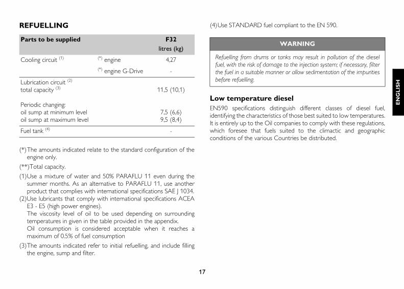
REFUELLING
(*)The amounts indicated relate to the standard configuration of theengine only.
(**)Total capacity.
(1)Use a mixture of water and 50% PARAFLU 11 even during thesummer months. As an alternative to PARAFLU 11, use anotherproduct that complies with international specifications SAE J 1034.
(2)Use lubricants that comply with international specifications ACEAE3 - E5 (high power engines).The viscosity level of oil to be used depending on surroundingtemperatures in given in the table provided in the appendix.Oil consumption is considered acceptable when it reaches amaximum of 0.5% of fuel consumption
(3)The amounts indicated refer to initial refuelling, and include fillingthe engine, sump and filter.
(4)Use STANDARD fuel compliant to the EN 590.
Low temperature dieselEN590 specifications distinguish different classes of diesel fuel,identifying the characteristics of those best suited to low temperatures.It is entirely up to the Oil companies to comply with these regulations,which foresee that fuels suited to the climactic and geographicconditions of the various Countries be distributed.
Parts to be supplied F32litres (kg)
Cooling circuit (1) (*) engine 4,27 (*) engine G-Drive -
Lubrication circuit (2)
total capacity (3)
Periodic changing:oil sump at minimum leveloil sump at maximum level
11,5 (10,1)
7,5 (6,6)9,5 (8,4)
Fuel tank (4) -
WARNING
Refuelling from drums or tanks may result in pollution of the dieselfuel, with the risk of damage to the injection system; if necessary, filterthe fuel in a suitable manner or allow sedimentation of the impuritiesbefore refuelling.

18
FREQUENCYThe maintenance intervals indicated below take into account thetypical working factors for various types of engine use; the mostsuitable interval for maintenance operations for the variousapplications will be indicated by the maintenance staff, according to theway and working conditions in which the engine is used.
Controls (when in use) Frequency
Engine visual inspection Daily
Check for water in the fuel filter/pre-filter Daily
Check engine oil level Daily
Check cooling liquid level Daily
Check air filter Daily
Check/top up electrolyte levelin batteries and clean terminals Half-yearly
Planned maintenance Frequency
Check the wear conditions of the alternator’s belt and of the water pump 300 hours (2)
Change engine oil 500 hours (3) (4)
Replace engine oil filter 500 hours (3) (4) (5)
Replace fuel filter 600 hours (1) (3) (5)
Change auxiliary member belt 1200 hours
Change air filter 1200 hours (6)
Change coolant1200 hours or 2 years
Replace fuel pre-filter 1000 hours (1)
Special maintenance Frequency
Tappet check and adjustment 1000 hours (7)
Check turbo-compressor and clean it if necessary 1200 hours
Ignition pump overhaul 3000 hours

19
EN
GL
ISH
1) Maximum period when using good quality fuel, (EN 590 standard);this is reduced if the fuel is contaminated and alarms are triggereddue to blockage of the filters and presence of water in the pre-filter.When blockage of the filter is indicated, it must be replaced. If thewater in pre-filter indicator does not go out after drainage, the pre-filter must be replaced.
2) Refers to engines with traditional and automatic tensioning devices
3) Must be performed annually, even if the required number ofworking hours are not reached
4) Replace lubricants according to the frequency indicated in theREFUELLING table.
5) Only use filters with the following characteristics:
- filtration level < 12 µm - filtering efficiency ß > 200.
6) The frequency with which operations are carried out will dependon the working conditions and efficiency/wear of the product.
7) Required by oil vapour recirculation.
HOW TO PROCEEDCheck oil level in engineOnly proceed with the engine stopped and at a low temperature, soas to avoid the risk of burning.
Take all necessary action to ensure that the machine is “level”.Using the dipstick (2), check that the oil level is between the "Min"and "Max" levels.If the level is too low, top up through the inlet, after first removingthe relevant cap (1)..
WARNING
The extraordinary maintenance operations describedhereunder fall within the exclusive competence ofmanufacturer’s personnel or specialised personnel havingproper working tools and adequate protection devices. Theprocedure and modality for carrying out these operationsare illustrated in the FPT Technical and Repair Manual.
09_007_F

20
Check coolant levelProceed only with engine not running and at low temperature to avoidany risk of burns.
With the engine cold, make sure that the level of liquid inside theheat exchanger is sufficient to cover the heat exchanger elements.
Top up the tank if necessary, using clean water. Do not use distilledwater; see the table REFUELLING.
Note: If the refill operations occur frequently a diagnosis of thecooling circuit is necessary.
In the event that only the heat exchanger without the expansion tankis available on the vehicle, refill it if necessary, paying attention that thefluid does not saturate the internal volume of the exchanger in orderto enable any increase in volume of the fluid caused by thetemperature increase.
WARNINGS
After topping up, make sure that the oil level does not exceed the"Max" limit marked on the dipstick.
Make sure that the dipstick is inserted properly and the filler capis turned in a clockwise direction until it stops turning completely.
CAUTION!
When the engine is warm, a pressure liable to cause hotliquid to be expelled with extreme violence is createdwithin the cooling circuits. This results in a danger ofburning.

21
EN
GL
ISH
Clean heat exchangersCheck that the radiator air inlets are free from dirt (dust, mud, straw,etc.). Clean them if necessary, using compressed air or steam.
Cleaning the air filterOnly proceed with the engine stopped.
If necessary, remove the rear manoeuvring hook (1).
Remove the filter cover (4) after first freeing the two snap hooks(3).
Extract the main cartridge (2). During this operation, take care toensure that no dust gets into the sleeve.
Check that there is no dirt. If there is, clean the filter element asindicated below.
Blow dry compressed air through the filter element, from the insideoutward (maximum pressure 200 kPa). Do not use detergents; donot use diesel.
Never use tools to beat the filter element, and check its conditionbefore replacing it.
Replace the filter if any breakages or tears are found.
Check that the gasket at its base is in good condition.
Reassemble by repeating the above operations in reverse order.
If the rear manoeuvring hook (1) has been removed, fix it to theflywheel cover casing by tightening the fixing screws to a torque of70 ±7 Nm.
CAUTION!
The use of compressed air makes it necessary to usesuitable protective equipment for the hands, face andeyes. Please see the prescriptions in the paragraph onACCIDENT PREVENTION.
05_609_N

22
Drain water from the fuel pre-filter and fuel filterThe high risk of refuelling with fuel that is polluted by foreign bodiesand water makes it advisable to carry out this control every time yourefuel.Proceed with the engine stopped.
Place a container under the filter or pre-filter to collect the fluid.
Unscrew the tap plug (1) in the bottom part of the filter; in somelay-outs the plug includes a sensor to detect the presence of waterin the diesel.
Drain off liquid until only “diesel” can be seen.
Close the plug again, tightening it completely by hand.
Dispose of the drained fluids according to current requirements.
WARNING
Take care to ensure that the parts are reassembled correctly.Imperfect assembly might result in unfiltered air being sucked into theengine, causing serious damage.
08_005_F
08_013_F

23
EN
GL
ISH
Check/top up electrolyte level in batteriesPlace the batteries on a level surface, then proceed as follows.
Visually check that the fluid level is between the “Min” and “Max”limits; in the absence of references, check that the fluid covers theLead plates inside the elements.
Top up with distilled water only those elements in which the levelis below the minimum.
Contact specialised technical staff if the battery needs recharging.
Have the efficiency of the battery recharging system tested if avoltage of less than 11 V (for 12 V rated systems) or 22 V (for24 V rated systems) is detected with the engine running.
On this occasion, make sure that the terminals and clamps areclean, properly locked and protected by vaseline.
Some types of battery havea single cover for all the inspection plugs.To access the elements, use a lever as shown in the figure.
CAUTION!
The batteries contain sulphuric acid, which is extremelycaustic and corrosive; always wear protective gloves andgoggles when topping them up. Whenever possible it isrecommended that this control be carried out byspecialised personnel.
Do not smoke or use live flames near the batteriesduring the control, and make sure that the room you areworking in is adequately ventilated.
04_362_N

24
Restore the correct tension in the auxiliary member drive belt
Loosen the screw fixing the bracket to the crankcase (1).Loosen the counternut (5).Loosen the nut (3) fixing the alternator to the support.Screw the tensioner (4) until the slot of the fixing bracket (2) isflush with the screw (1) as shown in the figure.On reaching the required belt tension, tighten the fixing screw (1),the counternut (5) and the nut (3).
.
Change oilOnly proceed with the engine stopped and at a low temperature, soas to avoid the risk of burning.
Unscrew the oil filler plug (1) located on the tappet cover andextract theengine oil dipstick (2).
Connect a suitable drainage pipe, extending outside, to the pump(3) mounted on the engine.
Extract the oil contained in the engine oil sump by operating thedrainage pump (3).
Fill up through the feeder hole (1) on the timer cover, using thetypes and amounts of oil indicated in the table REFUELLING.
Using the dipstick (2), check that the oil level is between the "Min"and "Max" levels.
Dispose of used oil according to current requirements.
.
WARNING
Replace the belt if any abrasion, cracking or tearing is seen, and if oilor fuel has spilled onto the belt.
08_006_F
08_007_F
25
EN
GL
ISH
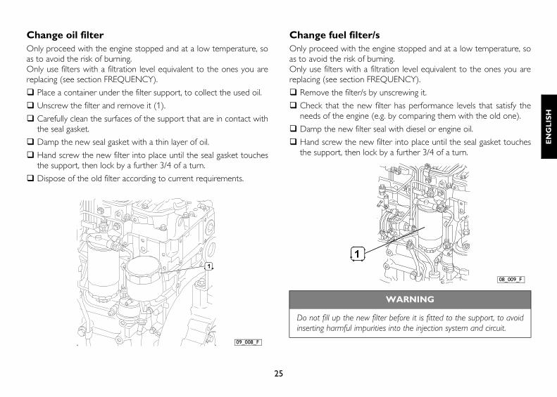
Change oil filterOnly proceed with the engine stopped and at a low temperature, soas to avoid the risk of burning.Only use filters with a filtration level equivalent to the ones you arereplacing (see section FREQUENCY).
Place a container under the filter support, to collect the used oil.
Unscrew the filter and remove it (1).
Carefully clean the surfaces of the support that are in contact withthe seal gasket.
Damp the new seal gasket with a thin layer of oil.
Hand screw the new filter into place until the seal gasket touchesthe support, then lock by a further 3/4 of a turn.
Dispose of the old filter according to current requirements.
Change fuel filter/sOnly proceed with the engine stopped and at a low temperature, soas to avoid the risk of burning.Only use filters with a filtration level equivalent to the ones you arereplacing (see section FREQUENCY).
Remove the filter/s by unscrewing it.
Check that the new filter has performance levels that satisfy theneeds of the engine (e.g. by comparing them with the old one).
Damp the new filter seal with diesel or engine oil.
Hand screw the new filter into place until the seal gasket touchesthe support, then lock by a further 3/4 of a turn.
09_008_F
WARNING
Do not fill up the new filter before it is fitted to the support, to avoidinserting harmful impurities into the injection system and circuit.
08_009_F

26
Bleeding procedure:
Loosen the fuel outlet manifold, located on the upper part of thefilter (1).
Make sure that any diesel coming out will not dirty the auxiliarymember drive belt or be dispersed into the environment.
Use the pre-filter hand pump until the diesel coming out is freefrom any residual air or perform the same operation using themechanical feed pump (2).
Lock the manifold loosened as above to the required torque.
Dispose of any diesel expelled during the above operation inaccordance with the law.
Start the engine and run it at minimum speed for a few minutes toeliminate any residual air.
Note: Should it be necessary to accelerate the bleeding phase, thehand pump can be used during start-up.
08_010_F
27
EN
GL
ISH
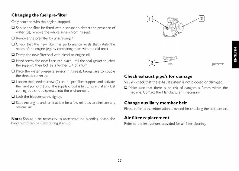
Changing the fuel pre-filter
Only proceed with the engine stopped.
Should the filter be fitted with a sensor to detect the presence ofwater (3), remove the whole sensor from its seat.
Remove the pre-filter by unscrewing it.
Check that the new filter has performance levels that satisfy theneeds of the engine (e.g. by comparing them with the old one).
Damp the new filter seal with diesel or engine oil.
Hand screw the new filter into place until the seal gasket touchesthe support, then lock by a further 3/4 of a turn.
Place the water presence sensor in its seat, taking care to couplethe threads correctly.
Loosen the bleeder screw (2) on the pre-filter support and activatethe hand pump (1) until the supply circuit is full. Ensure that any fuelcoming out is not dispersed into the environment.
Lock the bleeder screw tightly.
Start the engine and run it at idle for a few minutes to eliminate anyresidual air.
Note: Should it be necessary to accelerate the bleeding phase, thehand pump can be used during start-up.
Check exhaust pipe/s for damageVisually check that the exhaust system is not blocked or damaged.
Make sure that there is no risk of dangerous fumes within themachine. Contact the Manufacturer if necessary.
Change auxiliary member beltPlease refer to the information provided for checking the belt tension.
Air filter replacementRefer to the instructions provided for air filter cleaning.
08_012_F

28
Change coolantOnly proceed with the engine stopped and at a low temperature, soas to avoid the risk of burning.
Provide suitable containers to ensure that no coolant is dispersedinto the environment.
Loosen the seal elements, remove the sleeves connecting theengine circuit to the heat exchanger and wait until it has emptiedcompletely. When empty, repair the circuit making sure that thesleeves are perfectly sealed.
Fill up the circuit as indicated in the table REFUELLING.
Refill the engine and the heat exchanger until complete top up.
With the filler cap open, start the engine and keep it idling for nearlyone minute. This phase facilitates the cooling liquid air bleed.
Stop the engine and top up again.
MOVING THE ENGINEThe operations necessary to disconnect and subsequently reconnectthe engine must only be carried out by technicians from ServiceCentres.When lifting the engine only, use the U-bolts indicated in this manualin the section ENGINE TECHNICAL DATA.Lifting must be carried out using a rocker arm that keeps the metalcables supporting the engine parallel, using all the U-bolts providedsimultaneously; the use of a single U-bolt only is not allowed.The engine lifting system must have a capacity and size suited to theweight and dimensions of the engine; check that there is nointerference between the lifting system and the engine components.Do not lift the engine before removing the transmission members thatare coupled to it.
DISPOSAL OF WASTEThe engine is made up of parts and elements that, if discarded, maycause damage to the environment.The materials listed below must be handed over to specialisedCollection Centres; the laws in force in the various Countries foreseesevere penalties for transgressors:
Starter batteries.
Used lubricants.
Mixtures of water and antifreeze.
Filters.
Additional cleaning materials (e.g. greasy or fuel-soaked cloths).

29
EN
GL
ISH
LONG PERIODS OF INACTIVITY
PREPARING THE ENGINE FOR A LONG PERIOD OF INACTIVITYIn order to prevent oxidation of the internal parts of the engine andof certain components in the injection system, when the engine isexpected to be inoperative for periods of more than two months, thefollowing operations must be carried out in preparation for this:
1. Drain the lubricant from the sump, after first warming up theengine.
2. Fill the engine with protective oil type 30/M (or alternatively oil thatcomplies with MIL 2160B type 2 specifications), up to the"minimum" level indicated on the dipstick. Start the engine and keepit running for approximately 5 minutes.
3. Drain the fuel from the injection circuit, from the filter and from theinjection pump pipes.
4. Connect the fuel circuit to a tank containing CFB (ISO 4113)protective fluid, and feed in the fluid by putting the circuit underpressure and running the engine for approximately 2 minutes, afterfirst disabling the injection system. This operation can be performedby polarising terminal 50 of the starter motor with a positivevoltage equivalent to the rated voltage of the system, using aconductor provided for that purpose.
5. Nebulise approximately -- g of 30/M protective oil (10 g per litredisplacement) into the turbocharger suction inlet, during thepressurised filling operation described in the previous point.
6. Close all the suction, delivery, ventilation and bleeder openings inthe engine with suitable plugs, or seal them with adhesive tape.
7. Drain the residual 30/M protective oil from the sump. This oil canbe used again for a further 2 preparation operations.
8. Fit signs reading "ENGINE WITHOUT OIL" to the engine and tothe on-board control panel.
9. Drain the coolant, if it has not been mixed with suitable antifreezeand corrosion inhibitors, and affix a sign to indicate the fact.
In the event of prolonged inactivity, the operations described must berepeated every 6 months, following the procedure given below:
A) drain the 30/M protective oil from the sump;
B) repeat the operations described from point 2 to point 7.
Should you intend to protect external parts of the engine, proceed byspraying OVER 19 AR protective liquid on unpainted metal parts, suchas the flywheel, pulleys and the like, avoiding belts, connector cablesand electrical equipment.
30
RESTARTING THE ENGINE AFTER A LONG PERIOD OF INACTIVITY1. Drain the residual 30/M protective oil from the sump.
2. Fill the engine, as prescribed, with lubricant of the type and amountindicated in the table REFUELLING.
3. Drain the CFB protective fluid from the fuel circuit, carrying out thisoperation as indicated under point 3. of PREPARING THEENGINE FOR A LONG PERIOD OF INACTIVITY.
4. Remove the plugs and/or seals from the suction, delivery,ventilation and bleeder openings in the engine, restoring it to anormal state of use. Connect the turbocharger suction inlet to theair filter.
5. Connect the fuel circuits to the machine’s fuel tank, completing theoperations as indicated in point 4. of PREPARING THE ENGINEFOR A LONG PERIOD OF INACTIVITY. During fillingoperations, connect the fuel return pipe to a collection tank, so asto prevent any residual CFB protective fluid from flowing into themachine's fuel tank.
6. Check the engine and fill it up with coolant as prescribed, bleedingit if necessary.
7. Start the engine and keep it running until the idling speed rate hasstabilised completely.
8. Check that the instruments on the on-board control panel/s areshowing plausible values, and that no alarms are shown.
9. Stop the engine.
10. Remove the "ENGINE WITHOUT OIL" signs from the engine andfrom the on-board control panel.

31
EN
GL
ISH
BEHAVIOUR IN AN EMERGENCY
The user of a machine that has been constructed according to safetyregulations, when following the instructions provided in this manualand the indications given on the engine labels, will be working in safeconditions.Should improper conduct result in accidents, always request theintervention of trained first aid specialists immediately.In an emergency and while awaiting the arrival of first aid specialists,follow the instructions given below.
Engine malfunctionsWhen operating with a malfunctioning engine, take the greatestpossible care when manouevering and make sure that all those aboardare holding firmly to safe hand-holds.
In case of fireExtinguish the fire using the fire-fighting equipment foreseen, and inthe manner indicated by Fire prevention authorities (fire-fightingequipment for certain machines and equipment is compulsory undercurrent safety legislation).
Burns and scalds1. Extinguish any flames on the burned person's clothing, by:
• throwing water over them;
• using a powder fire-extinguisher, without directing the jet at theperson's face;
• covering with blankets or rolling the victim on the ground.
2. Do not attempt to remove pieces of clothing that may have stuckto the skin;
3. In the case of scalding, immediately but carefully remove anyclothing that may be soaked in the hot liquid;
4. Cover the burn with a special burn dressing or sterile bandage.
Carbon monoxide intoxication (CO)Carbon monoxide from the engine exhaust is without smell, and isdangerous both because it causes intoxication, and because whencombined with air it forms an explosive mixture.In closed rooms, carbon monoxide is extremely dangerous, as it canreach critical concentrations within a very short time.When assisting an intoxicated person in a closed room:
1. Ventilate the room immediately, to reduce the concentration ofgas.
2. When entering the room, hold your breath, do not light flames,lights or ring electric doorbells or phones, to avoid the risk ofexplosion.
3. Carry the intoxicated person out into the fresh air or into a wellventilated room, resting him on one side if he is unconscious.

32
ElectrocutionA. The engine's electrical 12 V or 24 V electrical system does not
involve the risk of electrocution, however, in the event of a short-circuit caused, for example, by a metal tool, there is a risk of burningdue to overheating of the object through which the electricalcurrent runs. In these circumstances:
1. Remove the object that caused the short-circuit, using means thatprovide sufficient heat insulation.
2. Switch off the power at the main switch, if there is one.
B. The electric generator systems (generator units) normally producehigh voltages that are liable to result in extremely dangerouscurrent levels. In the event of medium or high voltage electrocution:
1. Turn off the power supply at the main switch before touching thevictim. If this is not possible, use equipment that is both safe andadequately insulated when touching the victim; remember thattouching a victim of electrocution is also extremely dangerous forthe person giving aid.
2. Proceed as indicated by the competent authorities (cardiacmassage, mouth-to-mouth resuscitation, etc.)
Injuries and fracturesThe vast number of possible circumstances and the specific nature ofoperations required means that the intervention of a medical team isnecessary.
1. In the event of bleeding, keep the edges of the wound pressedtogether until help arrives.
2. If there is any suspicion of a fracture, do not move the injured partand only move the patient if absolutely necessary.
Caustic burnsCaustic skin burns are caused by contact with extremely acid oralkaline substances.For electric maintenance technicians these are typically caused by acidfrom batteries; in these circumstances, proceed as follows:
1. Remove any clothing soaked in the caustic substance.
2. Wash the area with lots of running water, avoiding parts that havenot been burned.
If either battery acid, lubricants or diesel come into contact with theeyes: wash the eyes with water for at least 20 minutes, keeping theeyelids open so that the water flows over the eyeball (move the eyein all directions to wash more thoroughly).

33
EN
GL
ISH

34