
IV COMUICATIdNS AND ELATED PROJECTS This project was …
26
IV COMUICATIdNS AND ELATED PROJECTS This project was begun in November 1945 in an attempt to determine the system or systems of modulation that give most efficient utilization of spectrum and power Although it might be thought that the age of this general problem would mean that all of its complexities had been unraveled, such is not the case by any means War-time developments in circuits and war-nurtured viewpoints have caused many changes in those communication techniques accepted as standard and, it is believed can cause even more The use of microwaves for the relaying of television or of many voice circuits or of meter readings has brought with it many new problems as well as a distinct reluctance to accept the old answers as the final ones Further there has been a distinct feel- ing that some communication systems have grown by the compounding of a series of hasty development projects, each aimed at solving a particular problem in the most expeditious way rather than by planned fundamental research Accordingly it was planned to combine a general fundamental study of the communication process with several detailed studies of problems which it was believed, were worthy of detailed fundamental analysis The detailed problems first selected for study were those associated with the Pound stabilized microwave oscillator This study resulted in a program which, as will be seen, has con- tinued ever since As the general analysis proceeded, specific problems accumulated in connection with it and these problems have been studied to the limit of available man power The general communication problem may be readily resolved into a study of the effects of various types of noise and interference on communications system Types of noise and interference considered are thermal or "white" noise impulse noise, adjacent channel interference, common channel interference and that special type of common channel interference known as multipath interference The effects of these types of noise and interference on amplitude-modulated signals are moderately well known but theory and experiment are rather inconclusive in the realms of frequency and pulse modulation, where exact theories have rarely been published and experiments have rarely been duplicated Accordingly, prime consideration has been given to the various types of pulse and frequency modulation. Detailed problems considered have been analyses of the modulation and demodu- lation process studies of the fundamental characteristics of thermal and impulse noise, and the response of ideal and actual receivers to the latter experimental and theoretical studies of the FM receiver discriminator and limiter system studies of pulse modulation components and the analogue analysis of multipath transmission In addition to these problems, all concerned basically with the interaction of signal and noise or interference the Pound oscillator has been analysed in detail its modulation problems considered and its improvement attained Detailed discussions of all of these projects follow A MODUIATION STUDIES SPECTRUM UTILIZATION EFFICIENCY OF POWER UTILIZATION SIGNAL-TO-NOISE RATIOS 1 General Analysis of the Transmission of Information Staff W G Tuller Analyses made in the past have arrived at the conclusion that the quantity of information that may be transmitted over a given bandwidth in a given period of time -55-
Transcript of IV COMUICATIdNS AND ELATED PROJECTS This project was …
IV COMUICATIdNS AND ELATED PROJECTS
This project was begun in November 1945 in an attempt to determine the system
or systems of modulation that give most efficient utilization of spectrum and power
Although it might be thought that the age of this general problem would mean that all
of its complexities had been unraveled, such is not the case by any means War-time
developments in circuits and war-nurtured viewpoints have caused many changes in those
communication techniques accepted as standard and, it is believed can cause even more
The use of microwaves for the relaying of television or of many voice circuits or of
meter readings has brought with it many new problems as well as a distinct reluctance
to accept the old answers as the final ones Further there has been a distinct feel-
ing that some communication systems have grown by the compounding of a series of hasty
development projects, each aimed at solving a particular problem in the most expeditious
way rather than by planned fundamental research Accordingly it was planned to combine
a general fundamental study of the communication process with several detailed studies
of problems which it was believed, were worthy of detailed fundamental analysis The
detailed problems first selected for study were those associated with the Pound stabilized
microwave oscillator This study resulted in a program which, as will be seen, has con-
tinued ever since As the general analysis proceeded, specific problems accumulated in
connection with it and these problems have been studied to the limit of available man
power
The general communication problem may be readily resolved into a study of the
effects of various types of noise and interference on communications system Types of
noise and interference considered are thermal or "white" noise impulse noise, adjacent
channel interference, common channel interference and that special type of common channel
interference known as multipath interference The effects of these types of noise and
interference on amplitude-modulated signals are moderately well known but theory and
experiment are rather inconclusive in the realms of frequency and pulse modulation, where
exact theories have rarely been published and experiments have rarely been duplicated
Accordingly, prime consideration has been given to the various types of pulse and frequency
modulation. Detailed problems considered have been analyses of the modulation and demodu-
lation process studies of the fundamental characteristics of thermal and impulse noise,
and the response of ideal and actual receivers to the latter experimental and theoretical
studies of the FM receiver discriminator and limiter system studies of pulse modulation
components and the analogue analysis of multipath transmission In addition to these
problems, all concerned basically with the interaction of signal and noise or interference
the Pound oscillator has been analysed in detail its modulation problems considered and
its improvement attained Detailed discussions of all of these projects follow
A MODUIATION STUDIES SPECTRUM UTILIZATION EFFICIENCY OF POWER UTILIZATIONSIGNAL-TO-NOISE RATIOS
1 General Analysis of the Transmission of Information
Staff W G Tuller
Analyses made in the past have arrived at the conclusion that the quantity of
information that may be transmitted over a given bandwidth in a given period of time
-55-

is limited1, 2 These analyses have been studied here in some detail, and it has been
shown that they apply to conventional systems of modulation It has also been shown
however that coding systems may be devised which have the property of apparently com-
pressing the information so that in the limit an infinite amount of information may
be transmitted in zero time and zero bandwidth To show this it need only be
shown that one point, determined to infinite accuracy conveys an infinite amount
of information, and that a point may be determined to infinite accuracy in zero
time if the transmission characteristics of the system are exactly known and no
noise is nresent A theoretical limit is reached in that the point may be determined
only to within a quantith where h is Planck's constant but this fact is of negli-
gible importance and has no bearing on the "unit of information" defined by Gabor
The clue to the practical resolution of the situation described above lies
in the statement that no noise is present Once thermal noise or other interference,
is allowed, a limit does exist and an expression may be written relating the power
bandwidth, noise, and time of transmission of a system This expression is
BT loge(l + S/N) = constant
where 3 is bandwidth, T time during which the system is available S signal strength,
and N noise strength3 The full implications of this exoression are now being studied
In the course of this general work much specific theoretical work has been
done on the analysis of various systems of modulation Some of the details of this
work have been published in a technical report 4 Others will be published in technical
reuorts now being written These include analyses of the signal versus noise behavior
of coded transmission systems and of pulse time modulation systems
2 Pulse Modulation Studies
Staff V G TullerE R Kretzmer
As was mentioned above, the recently announced systems of pulse modulation
still have many unsolved problems worthy of considerable research In an effort to
consider some of these problems as well as to gain better insight into the fundamentals
of operation of pulse modulation systems modulators and demodulators have been constructed
for pulse amplitude modulation, pulse duration modulation and pulse posr.ion modulation
These units have not been constructed in any attempt to develop commercial or near-com-
mercial equipment, but to make available laboratory apparatus with which to investigate
system and component problems The pulse amplitude and pulse duration systems have been
considered in previous progress reports and will not be gone into in detail here since
1 R V L Hartley, "Transmission of Information", B S T J Z, 535, (1928)
2 D Gabor, "Theory of Communication", IEE (London), 93 Pt III, No 26429 (1946)
3 Similar expressions, it has recently been publicly announced, have been derivedindependently by Professor N Wiener of the MIT Mathematics Department andDr C Shannon of the Bell Telephone Laboratories
4 W G Tuller, "Distortion in FM Discriminators", RIE Technical Report No 1,March 8 1946
-56-
little work has been done on them recently Considerable time, however has been put
into the pulse position modulation system, as the most efficient of the pulse modulation
family A description of this apparatus and some of the theoretical work done follows
I a Practical Srstem Study
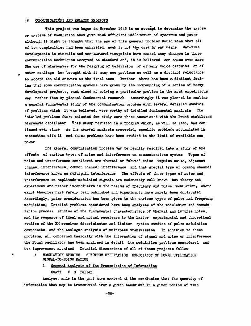
Description of System This study is concerned with the problems and performance of a
multi-channel pulse position (PPM) modulation system The system, in its present state,
consists of the following major components as shown in Fig 1
Figure 1 Over-all diagram of system
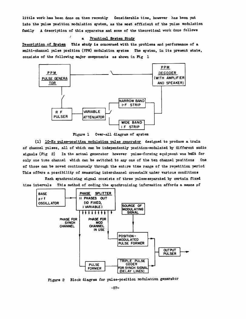
(1) 10-Kc pulse-position modulation pulse generator designed to produce a train
of channel pulses, all of which can be independently position-modulated by different audio
signals (Fig 2) In the actual generator however pulse-forming equipment was built for
only one time channel which can be switched to any one of the ten channel positions One
of these can be moved continuously through the entire time range of the repetition period
This offers a possibility of measuring interchannel crosstalk under various conditions
Each synchronizing signal consists of three pulsesseparated by certain fixed
time intervals This method of coding the synchronizing information affords a means of
PHASE FORSYNCH
CHANNEL
Figure 2 Block diagram for pulse-position modulation generator
-57-
distinguishing between it and the channel pulses as well as noise pulses
The component of principal interest in the generator is the position modula-
tor, which was investigated in considerable detail in order to arrive at a simple circuit
with good linearity (An audio oscillator or the output of a broldcast receiver serves
as a source of modulation )
The output stage of the unit is a biased blocking oscillator-type pulser,
which puts out all pulses at a low voltage low-impedance level and with a duration of
exactly one microsecond as determined by a delay line
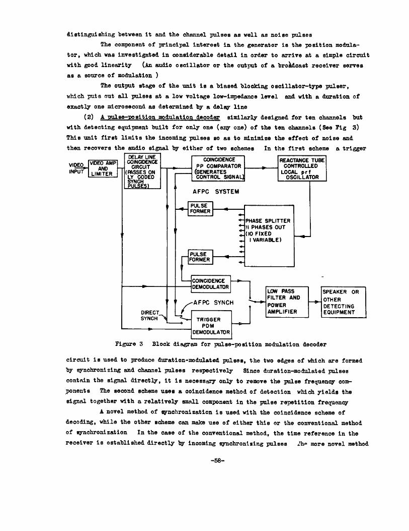
(2) A pulse-position modulation decoder similarly designed for ten channels but
with detecting equipment built for only one (any one) of the ten channels (See Fig 3)
This unit first limits the incoming pulses so as to minimize the effect of noise and
then recovers the audio signal by either of two schemes In the first scheme a trigger
VIDEO I AMP EN COINCIDENCE REACTANCE TUBEVE MVIDEO.r, . Maat I IAPIT [CD IVI E P 0P COMPDARATOR ONMTROLLED
-IN ANDINPUT LIMITER (FASSES ON
LY CODEDSYNCHPULSES)
--- fANRATFS I fal r f
~pCONTROL SIGNAL)M OSCILLATOR
AFPC SYSTEM
VULCFORMER
PULSEFORMER
PHASE SPLITTERII PHASES OUT(10 FIXED
I VARIABLE)
T
I U.MOULAUN IFigure 3 Block diagram for pulse-position modulation decoder
circuit is used to produce duration-modulated pulses, the two edges of which are formed
by synchronizing and channel pulses respectively Since duration-modulated pulses
contain the signal directly, it is necessary only to remove the pulse frequency com-
ponents The second scheme uses a coincidence method of detection which yields the
signal together with a relatively small component in the pulse repetition frequency
A novel method of synchronization is used with the coincidence scheme of
decoding, while the other scheme can make use of either this or the conventional method
of synchronization In the case of the conventional method, the time reference in the
receiver is established directly by incoming synchronizing pulses 2hp more novel method
-58-
1

which has been sucessfully used in television receivers , makes use of an automatic
frequency-phase control (AFPC) system The wave used for synchronization is derived only
indirectly from the synchronizing pulses and has a certain amount of "flywheel
momentum", which tends to make the all-important receiver synchronization more reli-
able in the presence of noise
The unit can easily be switched back knd forth between the various demodula-
tion and synchronization schemes for direct comparison through the output loud-speaker
or other detecting devices
The input video pulses to the unit may be obtained either directly from the
generator described above (1), or by way of r-f pulses with the equipment described in
the following paragraphs
(3) A radio-frequency oscillator to be pulsed by the generator described under
(1) This is simply a MK-3 test pulser modified for present purposes to be pulsed by
externally supplied pulses at either around 30 or around 60 Mc
(4) An adjustable coaxial attenuator, which although usually used in microwave
wort is suitable for insertion between the output of the pulsed oscillator (3) and the
i-f amplifier strips (5)
(5) Two i-f amplifier strips, designed for 30 and60 Me respectively, with respective
bandwidths of about 2 and 10 Mc Either one of these is fed with r-f pulses (see (4))
which after amplification, are enveloped-detected in the last stage and may then
be supplied to the decoder (2)
General.Attack The purpose of this equipment is to investigate the problems and character-
istics of the system and compare the latter with the expected results The problems are
mostly those encountered in connection with the operation of circuit components, while the
characteristics include susceptibility to noise, crosstalk interference, and so forth
The method of attack has been to set up the system trace through it systemati-
cally from the input of the transmitter to the output of the receiver and optimize the
performance of each stage or component in its turn
System gomonents and Problems Encountered Certain crucial system components which
required closer investigation will be briefly discussed The position modulator mentioned
under (1) must be reasonably linear over the modulation range produce pulses of low
"Jitter" and rise time to minimize noise have uniform frequency response, and the quies-
cent or average pulse position should have little dependence on supply voltages The
circuit used is essentially a regenerative overdriven amplifier operating on the linear
slope of the input sine wave and avoiding the use of RC coupling The output pulser of
(1) must supply pulses of duration independent of the characteristics of the driving
pulses and furthermore it must be capable of supplying pulses in rapid succession The
1 A Wright "Automatic Frequency-Phase Control in TV Receivers" Tele-Tech 6 74,Feb 1947
-59-
biased blocking oscillator using a delay line to cut the pulses short of their natural
duration was found to perform well, provided a relatively high-impedance pulse trans-
former is used
The limiter originally devised for the video portion of the receiving equip-
ment (2) made use of two type IN-34 crystals but it now consists merely of two suitably
biased amplifying pentodes The uroblem is that of taking a thin slice out of the middle
of a pulse Crystals are admirably suited for this purpose when the slicing level coin-
cides with the average value of the wave, e g in the case of an FM carrier In the pulse
application troubles due to d-c components have been encountered and the optimum
limiter design is still onen to question
The first demodulation scheme (2) uses a conventional trigger circuit followed
by a low-pass filter which must be nearly flat up to 3 5 kc and have at least 80 db
attenuation at the pulse repetition frequency of 10 kc A constant-k two-section
r filter in cascade with a bridge-T rejection network was found satisfactory
The second demodulation scheme (2) uses two coincidence tubes in a balanced
circuit one having more coincidence and hence more output for "forward" modulation and
the other likewise for "backward" modulation Careful adjustments of pulse durations
spacings and shaoes were found necessary to reduce distortion to near the level encoun-
tered in the first demodulation scheme Advantage can be taken of the balanced output
from the coincidence tubes by having it drive a pushpull amplifier so that the p r f
component is largely balanced out Unbalance resulting from relative drift between
the tmulses compared in the coincidence tubes results in a d-c component which is indicated
on a meter for easy balancing adjustment Apart from these advantages the "double
coincidence" method is expected to show a 3-db signal-to-noise improvement over other
methods while the signal level is raised 6 db the noise voltage should rise only 3 db
if the noise components riding on the two edges of the channel pulse are independent
Synchronization has undoubtedly presented the biggest single circuit problem
The conventional method of synchronization (2) presents no problem in the absence of
noise but this is not true of the automatic control synchronization system mentioned
under (2) While it was possible to obtain apparently satisfactory performance at the
expense of much time the desired flywheel effect is apparently not attained, and the
behavior of the system under certain conditions is not thoroughly understood While
there is little doubt that an automatic frequency and phase control system of synchroni-
zation offers definite adventages it is now believed that the varticular method of con-
trol used is impractical and should be replaced by one of the methods used in television1
The latter method is analogous to a uulsed servo2 receiving its error signal at regularly
spaced intervals, while in the automatic system used here the error pulses are irregu-
larly spaced with a certain degree of randomness Like the coincidence demodulation
scheme, the method is based on coincidence between received and locally generated
1 A Wright, loc cit
2 W Hurewicz "On Servos with Pulsed Error Data", RL Report 721 (April 26 1945)
-60-
pulses an error signal being produced each time a partial coincidence occurs An investi-
gation of the new methods used in television receivers is now under way
The radio-frequency portion of the system consisting of pulsed-oscillator
attenuator and i-f amplifier strip serves to make the system more realistic for the pur-
pose of measurements In particular it affords a simple method of introducing random
noise into the transmission path since the pulses fed to the i-f striD can be made com-
parable in amplitude to the thermal noise generated in the first stage. While the 30-Mc
narrow-band i-f strip performeA satisfactorily the 60-Mc wide-band i-f strio has not yet
given satisfactory results because of equinment difficulties
Qualitative Measurements Only rough qualitative apvraisals of over-all performance have
been made These will be briefly discussed
(1) Distortion With speech or music for modulation, average "broadcast receiver
quality" was obtained with both methods of demodulation Fidelity with the trigger method
of decoding is particularly good, since it depends only on the linearity of the modulator
and the spurious components inherently associated with duration-modulated pulses
[see Sec b. Theoretical Work] While the coincidence method of decoding has unnotice-
ably higher distortion with optimum adjustments the non-linear distortion becomes
noticeable when the vulses reaching the coincidence circuit detart from the ontimum shape
and duration (This condition could possibly be remedied by insertion of a triggered
pulser of the type used in the generator output ) Furthermore, with the coincidence
scheme used here the maximum total time swing in pulse position is limited to one pulse
duration No such limitation exists with the other method where linearity in the
modulator is the limiting factor Disregarding distortion a limit to the degree of
modulation is obviously set by the channel spacing From the preceding it may be con-
cluded that the trigger scheme of demodulation is mperior to the basic coincidence
scheme where high fidelity is a requirement
( 2) Noise With the pulse generator (1) feeding the decoder (2) directly (by-pass-
ing the r-f portion of the system) outout noise/signal is negligible with normal degree
of modulation Initially considerable trouble was had with 60-cycle noise which was
subsequently sufficiently reduced
When the r-f system is inserted with narrow-or wide-band i-f strip virtu-
ally identical results can be obtained when the pulses supplied are large compared to
thermal noise generated Thermal noise auickly becomes perceptible when the pulses are
reduced in amplitude relative to the noise As expected the effect is worse with the
narrow-band amplifier since the nulse edges are less steep and thus more susceptible
to time modulation by noise The point where the signal is almost completely masked bj
noise is reached when the average noise level a'pears to be somewhat below one-half
the pulse peaks at the output of the i-f strip (The corresmonding observation for the
wide-band i-f strip has not as yet been made ) It was found that at about the same
point, the automatic synchronization fails The trigger system of demodulation fails
at a considerably lower noise level On the other hard a comnarison in the working
range shows considerably more hiss noise with either demodul1tion scheme combined with
-61-
automatic synchronization th.n in the trigger scheme with direct synchronization This
must therefore be attributed to poor nerformance of the automatic control synchroniza-
tion This is born out by the fact that the hisq noise has a peak at one frequency
This noise is further found to depend on adjustments of limiter and other comoonents
The trigger scheme is subject to a characteristic objection-l popping noise, as the
breaking point is approached
Evidently a better synchronization circuit should be of orimary concern
both to imorove the system nerformance and to make quantitative noise measurements
possible
b Theoretical Work - F-rmonic Analyses
A paper entitled "Distorion in Pulse-Duration Modulation" previously mentioned
in the Progress Report of October 15 1946, has since been accepted for nublication in
the IRE Proceedings The distortion inherent in pulse duration modulation is found as a
function of modulation index and maximum signal-to-pulse frequency ratio The results
are also applicable to oulse position modulation if one uses the trigger scheme of con-
verting position modulation to duration modulation in the receiver (see above) For this
and most other applications inherent distortion is found to be at most a few per cent
provided the pulse repetition frequency is at least twice the highest modulation frequenc4
An analysis of a step-approximated wave (sampling at regular intervals) has
been made and presented in Technical Report No 12 It is found that a good approxima-
tlon to the actual wave is contained in the steoped wave so long as the sampling fre-
quency is at least twice the signal frequency Besides having direct application to
pulse amplitude modulation and certain other systems where sampling is used the results
are useful in certain general theoretical analyses
3 Proerties of Random Noise
Staff G E Duvall
The purpose of research being done under this program is to determine theoreti-
cally and experimentally the effects of transit time on shot noise in tubes used in com-
munication netuorks Experimental work, according to present plans, will be done using
"scale models" having relatively large transit times This will allow the work to be
done at low frequencies, so that the complicating effects of lead inductance and stray
capacity will be minimized It is hoped that the information obtained in the process of
these investigations will give a better insight into the significance and the effects
of transit time in tube operations of all kinds and that it will aid in the design and
development of lower noise tubes for high frequency operation
In the execution of these plans a large scale diode "a been constructed and
preparations are under way to measure the noise generated by +his diode under various
operating conditions
The spectrum of the noise from a temperature-limited parallel-plane diode has
been calculated and is shown in Fig 4 The shape of the current pulse in the anode of
the diode due to an election traveling from cathode to anode is shown in Fig 5 It is
orobable that these results anpear elsewhere but since they have not been found in a
random perusal of the literature it seems worthwhile reproducing them here
-62-

0 >.
-o
W0Cr WW j
U 0I_a N_ja. WCI -0
w TFigure 4 Power spectrum produced by pulses of Fig 5 added randomly
0 2 3t -
Figure 5 Pulsesproduced in tbe anode circuit of a plane-parallel diode byan electron traveling from cathode to anode with transit time Ti = instantaneous current e = electronic chnrge t = timemeasured from instant electron leaves cathode
-63-
IV A 4 The Action of Limiters and Discriminators in FM Receivers in the Presence
of Noise
Staff W G TullerT P Cheatham Jr
Description of Project One of the most serious limitations of the present FM system
of communications is the lack of an FM receiver which will closely realize the theoreti-
cal expectations of the system In this respect the correlation betueen the theoreti-
cal response of an ideal FM receiver to impulse noise and the respon e of the average
good FM commerci 1 receiver today is quite bad It is the main purnose of this study
to determine through analysis and exoeriment the reasons why theory and practice differ
and if possible to resolve this difference It is obvious that this difference if
resolved, may point the way to improved communications with frequency modulation
Status As previously reported, a theoretical analysis of impulse noise in an FM receiver
has been completed This analysis has covered the following points
(1) A determination of the response of a Foster-Seeley discriminator to a
scuare-wave modulated carrier and to the transient resulting from the injection of a d-c
pulse of short time duration at the input of the receiver has been made Expressions
have been derived for both the envel-oe of the resulting transient and the instantane-
ous phase of the resultant signal vector for the case of the square-wave modulated
carrier input
(2) An expression for the fractional deviation of the instantaneous frequency
of the resultant transient signal vector has been derived from the expression for the
instantaneous Thase
(3) A mathematical check has been made of the material presented by Messers
Bradley and Smith of the Philco Research Laboratories in their paper on "The Theory of
Impulse Noise in Ideal FM Receivers"1 Where anplicable this theory has been extended
and correlated with results oreviously derived above
(d) Ex-erimental work, usin oscillographic methods,has been carried out
concurrently with the theoretical work outlined above The experimental setup used will
be described later in this report
On the basis of the above analysis and certain experimental data the follow-
ing conclusions have been re ched
(1) The output of a Foster-Seeley discriminator is very nearly zero in both
its transient and steady-state components for any type of amplitude-modulated wave
provided the carrier freauency of the input wave is the same as the center frequencyr of
the discriminator
(2) The transient at the output of a discriminator mathematically equivalent
to a Foster-Seeley that has been adjusted for optimum counling is proportional to the
bandwidth of the discriminator and inversely proportional to the damping coefficient
(3) The time constants of the output filters of the detector of a Foster-
Seeley discriminator must be balanced to within about 6 per cent if impulse noise is to be
1 Proc IRE 34 743 (1946)
-64-
reduced to 50 db below maximum signal This balance is far less critical if a cathode-
driven discriminator1 is used in place of the conventional Foster-Seeley discriminator
(4) We agree with the Bradley and Smith division of impulse noise into two
basic types called "pops" and "clicks" and with their general conclusions
(5) The probability of the occurrence of a "click" or "pop" has been computed
for the following types of impulse noise
(a) ieriodic impulse noise of constant amplitude
(b) Random impulse noisehaving a distribution a-nproximated by the
Gaussian error curve
(c) Random impulse noise with sinusoidal amplitude distribution
(6) On the basis of the experessions and graph derived from (5) and with the addi-
tional provision that the capture time of the transient be sall compared to the time con-
stant of the de-emphasis network it can be said that while the amplitude of a "click"
is largely and that of a "pop" essentially indeoendent of the original noise impulse,
the probability of the occurrence of a "pop" or "click" is however dependent upon the
original noise impulse and in particular is a function of the following parameters
(a) Peak noise-to-signal ratio
(b) Number of stages in receiver filter
(c) Over-all receiver half-bandwidth
(d) Instantaneous frequency deviation of the desired signal
at the time of the impulse
(e) P(s)ds (the probability that a noise impulse peak ampli-
tude will lie between a and s+As)
(7) The receiver must be accurately tuned and aligned if the inherent
advantages of frequency modulation in discrimination against noise are to be realized
The detuning of the receiver under the action of the transient signal must be minimized
or eliminated
(8) The theoretical effect of impulse noise of even the "pop" variety on a
program signal should be negligible
Since the theory indicates that the effect of impulse noise should be negligi-
ble within very broad limits of amplitude and duration attention has been shifted to a
detailed study and analysis of limiters their functions and their effects on FM re-
ceiver performance This study has reached the point where it has been possible to
classify limiters into four general types
(1) "Slicer" limiters
(a) Center reference sub-type
(b) Peak reference sub-type
(2) Instantaneous amplitude control limiter
-65-
1 W G Tuller, T P Cheatham Jr "An Adjustable Band-Width FM Discriminator",RLE Tecnical Report No 6 June 30, 1946
(3) Zero crossing indicator limiters
(4) Limiters utilizing the oroperties of negative feedback of frequency-
modulated signals
The sub-division of the "slicer" type of limiter has been made because a
Fourier analysis shows distinct differences in the operation of the two sub-types
Experimental progress has been made on the design construction, and testing
of several specific limiter types The designs are gov rned by the theoretical
results obtained in the study of the characteristlcs of impulse noise Particular
attention has been paid to amolitude variations (rise time of the transient envelope)
capture time and instantaneous frequency variations
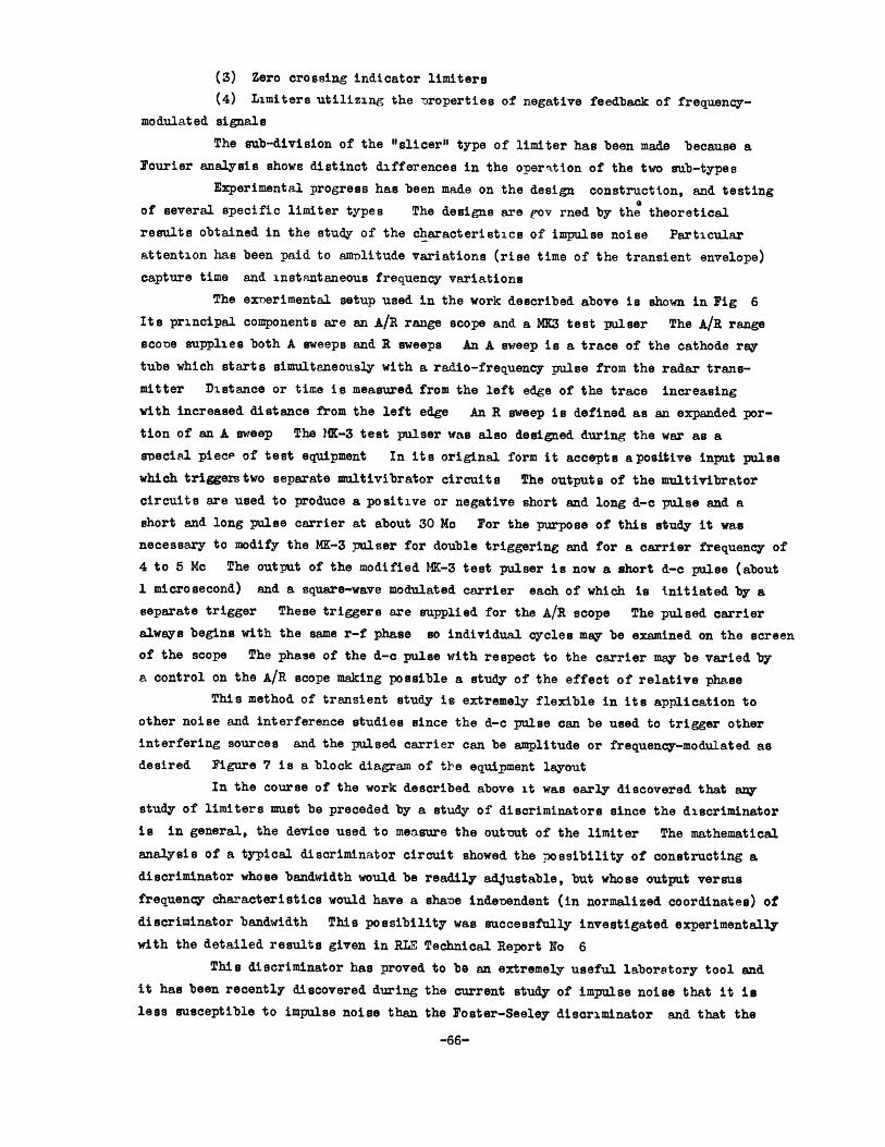
The exoerimental setup used in the work described above is shown in Fig 6
Its principal components are an A/R range scope and a MK3 test pulser The A/R range
sco-e supplies both A sweeps and R sweeps An A sweep is a trace of the cathode ray
tube which starts simultaneously with a radio-frequency pulse from the radar trans-
mitter Distance or time is measured from the left edge of the trace increasing
with increased distance from the left edge An R sweep is defined as an expanded por-
tion of an A sweep The MK-3 test pulser was also designed during the war as a
special piece of test equipment In its original form it accepts apositive input pulse
which triggerstwo separate multivibrator circuits The outputs of the multivibrator
circuits are used to produce a positive or negative short and long d-c pulse and a
short and long pulse carrier at about 30 Mc For the purpose of this study it was
necessary to modify the MK-3 pulser for double triggering and for a carrier frequency of
4 to 5 Me The output of the modified 1K-3 test pulser is now a short d-c pulse (about
1 microsecond) and a square-wave modulated carrier each of which is initiated by a
separate trigger These triggers are supplied for the A/R scope The pulsed carrier
always begins with the same r-f phase so individual cycles may be examined on the screen
of the scope The phase of the d-c pulse with respect to the carrier may be varied by
a control on the A/R scope making possible a study of the effect of relative phase
This method of transient study is extremely flexible in its application to
other noise and interference studies since the d-c pulse can be used to trigger other
interfering sources and the pulsed carrier can be amplitude or frequency-modulated as
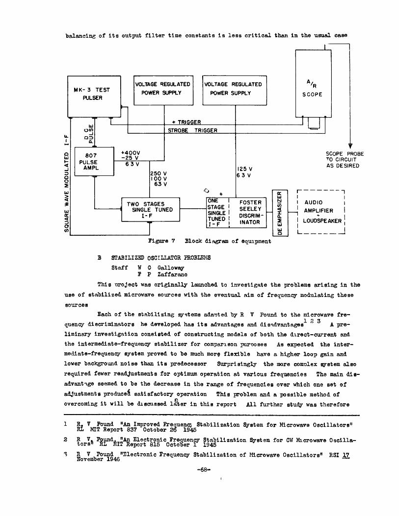
desired Figure 7 is a block diagram of tle equipment layout
In the course of the work described above it was early discovered that any
study of limiters must be preceded by a study of discriminators since the discriminator
is in general, the device used to measure the output of the limiter The mathematical
analysis of a typical discriminator circuit showed the possibility of constructing a
discriminator whose bandwidth would be readily adjustable, but whose output versus
frequency characteristics would have a shane indenendent (in normalized coordinates) of
discriminator bandwidth This possibility was successfully investigated experimentally
with the detailed results given in RLE Technical Report No 6
This discriminator has proved to be an extremely useful laboratory tool and
it has been recently discovered during the current study of impulse noise that it is
less susceptible to impulse noise than the Foster-Seeley discriminator and that the
-66-

I
PLSE AMPLIFIR
Figure 6. Experimental equipment used in the study of limiters and discriminators.
balancing of its output filter time constants is less critical than in the usual case
PROBE'UIT5IRED
Figure 7 Block diagram of equipment
B STABILIZED OSCILLATOR PROBLEMS
Staff W 0 GallowayF P Zaffarano
This nroject was originally launched to investigate the problems arising in the
use of stabilized microwave sources with the eventual aim of frequency modulating these
sources
Each of the stabilizing systems adanted by R V Pound to the microwave fre-123
quency discriminators he developed has its advantages and disadvantages A pre-liminary investigation consisted of constructing models of both the direct-current and
the intermediate-frequency stabilizer for comparison purooses As expected the inter-
mediate-frequency system proved to be much more flexible have a higher loop gain and
lower background noise than its predecessor Surprisingly the more comulex system also
required fewer readjustments for optimum operation at various frequencies The main dis-
advantage seemed to be the decrease in the range of frequencies over which one set of
adjustments produces satisfactory operation This problem and a possible method ofovercoming it will be discussed 12ter in this report All further study was therefore
1 R V Pound "An Improved Frequenc* Stabilization System for Microwave Oscillators"E MIT Report 837 October 26 1945
2 R V Pound "An Electronic Frequency Stabilization System for OW Microwave Oscilla-torsh RL AIT Report 815 October 1 1945
3 R V Pound "Electronic Frequency Stabilization of Microwave Oscillators" RSI 17November 1946
-68-
IUIT
limited to the more promising intermediate-frequency type of system.
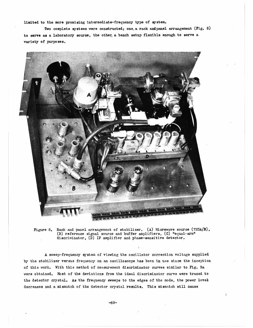
Two complete systems were constructed; one,a rack andpanel arrangement (Fig. 8)
to serve as a laboratory source, the other, a bench setup flexible enough to serve a
variety of purposes.
Figure 8. Rack and panel arrangement of stabilizer. (A) Microwave source (723A/3),(B) reference signal source and buffer amplifiers, (C) "equal-arm"discriminator, (D) IF amplifier and phase-sensitive detector.
A sweep-frequency system of viewing the oscillator correction voltage supplied
by the stabilizer versus frequency on an oscilloscope has been in use since the inception
of this work. With this method of measurement discriminator curves similar to Fig. 9a
were obtained. Most of the deviations from the ideal discriminator curve were traced to
the detector crystal. As the frequency sweeps to the edges of the mode, the power level
decreases and a mismatch of the detector crystal results. This mismatch will cause
-69-
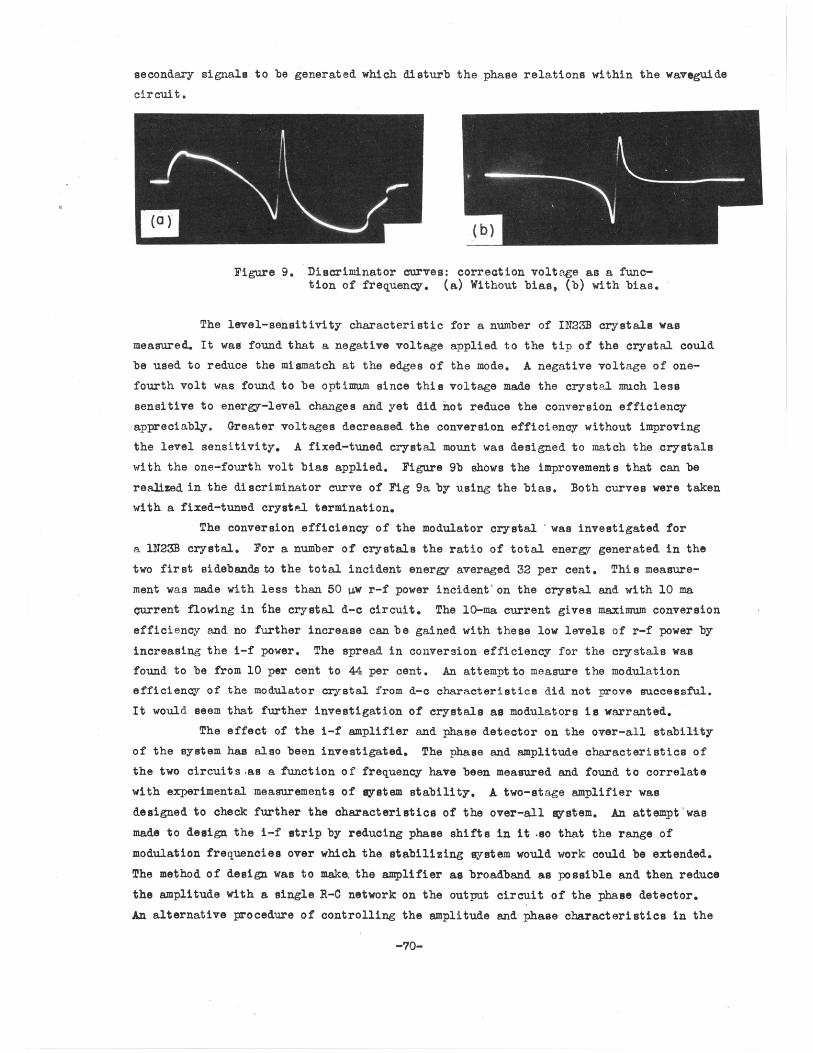
secondary signals to be generated which disturb the phase relations within the waveguide
circuit.
Figure 9. Discriminator curves: correction voltage as a func-tion of frequency. (a) Without bias, (b) with bias.
The level-sensitivity characteristic for a number of IN23B crystals was
measured. It was found that a negative voltage applied to the tip of the crystal could
be used to reduce the mismatch at the edges of the mode. A negative voltage of one-
fourth volt was found to be optimum since this voltage made the crystal much less
sensitive to energy-level changes and yet did not reduce the conversion efficiency
appreciably. Greater voltages decreased the conversion efficiency without improving
the level sensitivity. A fixed-tuned crystal mount was designed to match the crystals
with the one-fourth volt bias applied. Figure 9b shows the improvements that can be
realized in the discriminator curve of Fig 9a by using the bias. Both curves were taken
with a fixed-tuned crystal termination.
The conversion efficiency of the modulator crystal was investigated for
a lN23B crystal. For a number of crystals the ratio of total energy generated in the
two first sidebands to the total incident energy averaged 32 per cent. This measure-
ment was made with less than 50 pw r-f power incident' on the crystal and with 10 ma
qurrent flowing in the crystal d-c circuit. The 10-ma current gives maximum conversion
efficiency and no further increase can be gained with these low levels of r-f power by
increasing the i-f power. The spread in conversion efficiency for the crystals was
found to be from 10 per cent to 44 per cent. An attempt to measure the modulation
efficiency of the modulator crystal from d-c characteristics did not prove successful.
It would seem that further investigation of crystals as modulators is warranted.
The effect of the i-f amplifier and phase detector on the over-all stability
of the system has also been investigated. The phase and amplitude characteristics of
the two circuits as a function of frequency have been measured and found to correlate
with experimental measurements of system stability. A two-stage amplifier was
designed to check further the characteristics of the over-all system. An attempt 'was
made to design the i-f strip by reducing phase shifts in it .so that the range of
modulation frequencies over which the stabilizing system would work could be extended.
The method of design was to make, the amplifier as broadband as possible and then reduce
the amplitude with a single R-0 network on the output circuit of the phase detector.
An alternative procedure of controlling the amplitude and phase characteristics in the
-70-
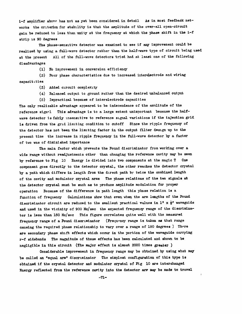
i-f amplifier above has not as yet been considered in detail As in most feedback net-
works the criterion for stability is that the amplitude of the over-all open-circuit
gain be reduced to less than unity at the frequency at which the phase shift in the i-f
strip Is 90 degrees
The phase-sensitive detector was examined to see if any improvement could be
realized by using a full-wave detector rather than the half-wave type of circuit being used
at the present All of the full-wave detectors tried had at least one of the following
disadvantages
(1) No improvement in conversion efficiency
(2) Poor phase characteristics due to increased interelectrode and wiring
capacitities
(3) Added circuit complexity
(4) Balanced output to ground rather than the desired unbalanced output
(5) Impractical because of interelectrode capacities
The only realizable advantage appeared to be independence of the amolitude of the
reference signol This advantage is to a large extent unimportant because the half-
wave detector is fairly insensitive to reference signal variations if the injection grid
is driven from the grid limiting condition to cutoff Since the ripple frequency of
the detector has not been the limiting factor in the output filter design up to the
present time the increase in ripple frequency in the full-wave detector by a factor
of two was of diminished importance
The main factor which prevents the Pound discriminator from working over a
wide range without readjustments other than changing the reference cavity may be seen
by reference to Fig 10 Energy is divided into two components at the magic T One
component goes directly to the detector crystal, the other reaches the detector crystal
by a path which differs in length from the direct path by twice the combined length
of the cavity and modulator crystal arms The phase relations of the two signals at
the detector crystal must be such as to produce amplitude modulation for proper
operation Because of the difference in path length this phase relation is a
function of frequency Calculations show that even when the arm lengths of the Pound
discriminator circuit are reduced to the smallest practical values in 1" x "in waveguide
and used in the vicinity of 900 Mc/sec the expected frequency range of the discrimina-
tor is less than 150 Mc/sec This figure correlates quite well with the measured
frequency range of a Pound discriminator (Frequoncy range is taken as that range
causing the required phase relationship to vary over a range of 180 degrees ) There
are secondary phase shift effects which occur in the portion of the waveguide carrying
r-f sidebands The magnitude of these effects has been calculated and shown to be
negligible in this circuit (The major effect is almost 2000 times greater )
Considerable improvement in frequency range may be obtained by using what may
be called an "equal arm" discriminator The simplest configuration of this type is
obtained if the crystal detector and modulator crystal of Fig 10 are interchanged
Energy reflected from the reference cavity into the detector arr may be made to travel
-71-

Figure 10 Block diagram of stabilizer with provision for con-tinous plotting of discriminator characteristic
the same length of path as energy reflected as i-f sidebands from the modulator crystal
With this discriminator frequency ranges of the order of 1000 Me with no adjustment
other than cavity tuning have been obtained An analysis of the operation of the equal-arm
discriminator is now in progress. An important dissimilarity between Pound's and this
discriminator is noted In the equal-arm circuit, the. detector crystal operates
normally on a signal composed of a constant sideband level and varying carrier amplitude
This is analogous to overmodulation since the carrier is normally nearly zero Large
amounts of second harmonic power are generated at the crystal and must be rejected by the
i-f amplifier There is reason to believe that increased sensitivity may result from
this mode of operation
Studies have been initiated on the operation of the stabilizer circuit when
the oscillator is frequency modulated The problem will be attacked by
(1) Determining the manner in which the discriminator characteristic as
determined by the reference cavity only controls distortion in the modulated output
(2) Determining the manner in which the i-f amplifier and phase-sensitive
detector affect the distortion in the modulated output
All studies will be done with the i-f system W G Tuller 1 has analyzed distortion in
the output of a discriminator for a pure frequency-modulated input -
1 W G Tuller "Distortion in FM Discriminators" RLE Tech Report No 1 March 8 1946
-72-
A recently completed report entitled "Notes on the Pound Microwave Frequency
Stabilizer" is now being prepared for publication (RL Technical Report No 31)
IV C MUIIIPATH TRANSMISSION
Staff Professor L B ArguimbauJohn Granlund
It has been long recognized that the fading interference caused by transmission
over two or more paths is one of the chief limitations to long distance transmission of
speech and music This project has been set up to study such effects under controlled
laboratory conditions with various types of modulation
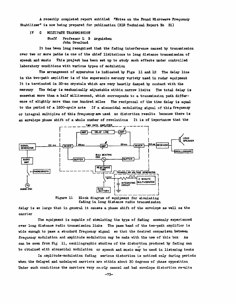
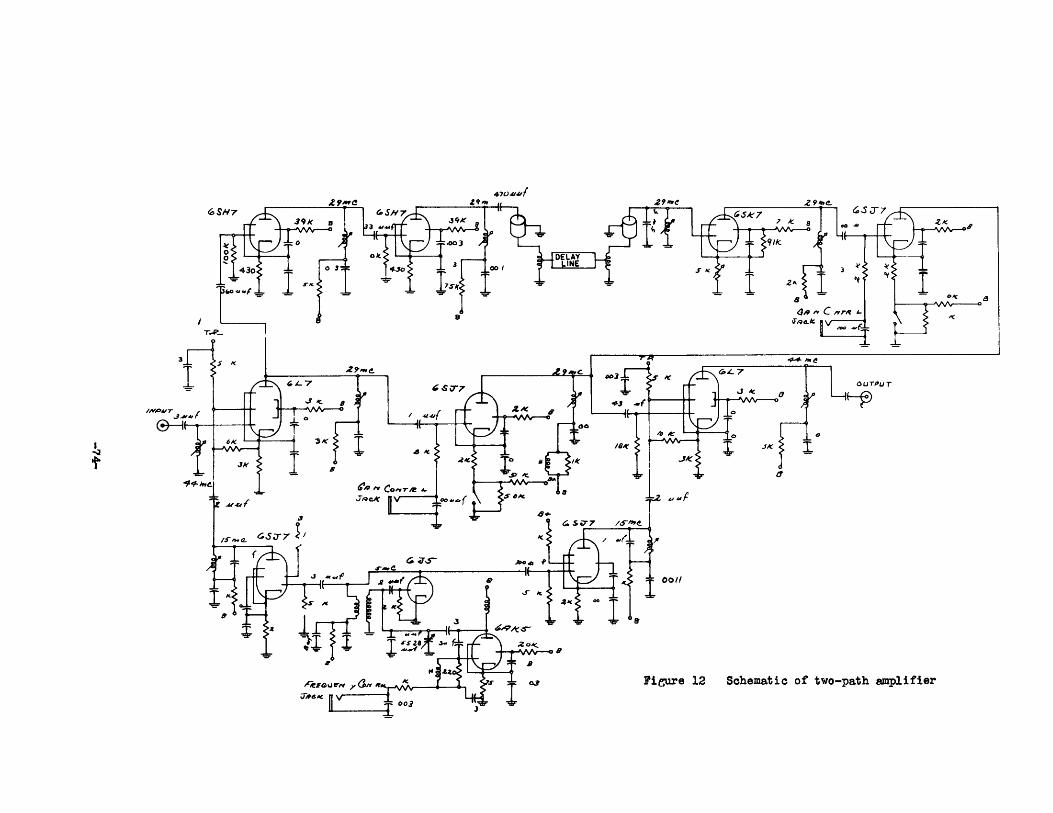
The arrangement of apparatus is indicated by Pigs 11 and 12 The delay line
in the two-path amplifier is of the supersonic mercury variety used in radar equipment
It is terminated in 30-me crystals which are very heavily damped by contact with the
mercury The delay is mechanically adjustable within narrow limits The total delay is
somewhat more than a half millisecond, which corresponds to a transmission path differ-
ence of slightly more than one hundred miles The reciprocal of the time delay is equal
to the period of a 1600-cycle note If a sinusoidal modulating signal of this frequency
or integral multiples of this frequencyare used no distortion results because there is
an envelope phase shift of a whole number of revolutions It is of importance that the
TWO PAT AMPLIFIER
IPLOUDI t~1ISPEAKER
m RECEIVER
JERATOR
2 MINUTEINTEGRATING IMLLnVRTOR
I CIRCUIT IAUDIO iSC BIAS
BATTERY -
Figure 11 Block diagram of equipment for simulatingfading in long distance radio transmission
delay is so large that in general it causes a phase shift of the envelope as well as the
carrier
The equipment is capable of simulating the type of fading commonly experienced
over long distance radio transmission links The pass band of the two-path amplifier is
wide enough to pass a standard frequency signal so that the desired comparison between
frequency modulation and amplitude modulation may be made with the use of this box As
can be seen from Fig 11, oscillographic studies of the distortion produced by fading can
be obtained with sinusoidal modulation or speech and music may be used in listening tests
In amplitude-modulation fading serious distortion is noticed only during periods
when the delayed and undelayed carriers are within about 30 degrees of phase opposition
Under such conditions the carriers very nearly cancel and bad envelope distortion results
-73-
O/01
Figure 12 Schematic of two-path amplifier
470411
/10V
,.Tq a./

To make the listening tests representative, it was decided to change the phase relation
of the combining carriers continously. With the system so arranged.the out-of-phase
condition recurs at about one-second intervals.
The circuits for producing this phase variation are the triangular voltage
generator and reactance tube shown in Fig 11. The phase difference between the delayed
and undelVaed carriers upon recombination is given by the product of the angular
frequency of transmission through the delay line and the time delay of the line. In a
physical transmission link, this phase difference is changed naturally by a change in
the relative transmission time of the two paths. In the laboratory model, however,
it is simpler to change the frequency. This change is made by changing the frequncy of
the beating oscillator, so that it is not necessary to change the tuning of the signal
generator and receiver simultaneously.
In frequency modulation the signal phase goes through wild gyrations in
the course of being modulated. Hence one might suspect that the phase difference
between the unmodulated carriers upon recombination is of little consequence. This has
been observed to be true with the laboratory setup. For this reason,the equipment for
producing continuously variable phase. is made inoperative in frequency-modulation tests.
The results on amplitude modulation are in agreement with the early studies
concerning fadingl. The waveforms so far obtained on frequency modulation are similar
Figure 13. Characteristic waveform of multipath interference in frequency modulation.Modulation frequency = 200 cycles.Frequency deviation = + 3000 cycles.De-emphasis time constant = 100 psec.Time delay = 625 psec.
Amplitude of delayed path is slightly greater than amplitude of undelayed path.
in appearance to those obtained-by others2,3,4, 5 . A characteristic waveform is shown in
1. R. Bown, D. K. Martin, R. K. Potter, "Some Studies in Radio Broadcast Transmission",Proc. IRE, 14, 57, (Feb. 1926)
2. M. G. Crosby, "Frequency Modulation Propagation Characteristics", Proc. IRE, 24,898, (June 1936)
3. M. G. Crosby, "Observation of Prequency-Modulation Propagation on 26 Megacycles",Proc. IRE, 29, 398, (July 1941).
It
4. E. HolslerVDE, F. H. Gecks, G. Kamphausen, "Ubertragung amplituden- undfrequens-modulierten Schwingungen auf kurzen Wellen", Elektrotechnische Zeitschrift, 65,133, (April 1944).
5. M. D. Corrington, "Frequency-Modulation Distortion CausedlVy Multipath Transmission",Proc. IRE, 38, 878, (Dec. 1945).
-75-

Fig 13 It is not difficult to compute the positions and magnitudes of the small dis-
turbances in most caes Some waveforms are less easily handled and depend upon receiver
charcteristics In spite of the agreement with earlier results there are indications
that freqaency modulation has certain advantages over amplitude modulation under
proper conditions
Incidental to the study of multipath transmission with amplitude modulation
and frequency modulation it is found that
(1) An amplitude-modulation link having a transmitter subject to incidental
frequency modulation may have very much more distdrtion than a similar link having a
transmitter that is stabilized in frequency
(2) A frequency-modulation link which is subject to incidental amplitude
modulation is more distorted than one which does not have amplitude variations intro-
duced at some point
IV D WIDEBAND AMPLIFIER STUDIES
Staff W G TullerH, H Montgomerv JrM W Whitaker Jr
The introduction of the various wideband systems of pulse modulation such
as pulse code modulation, has brought about a great need for amplifiers capable of
reascnable gains over extremely wide bands In the microwave region these requirements
are met by the travelling-wave amplifier tube but no equivalent to this device exists
at low frequencies At the suggestion of Professor H Wallman an amplifier circuit
has been built and tested which may be considered as a low frequency analogue of
the travelling-wave tube The circuit constructed is shown in simplified schematic
form in Fig 14 As can be seen from this figure the amplifier consists of three
Figure 14 Wideband video amplifier
amplifying tubes all 6AC7's, and an output cathodefollower The tubes are effectively
connected in parallel by delay lines between grids of adjacent tubes and similar
delay lines between plates of adjacent tubes The signal may be considered as propagat-
ing along the amplifier from left to right in the figure Suppose a negative pulse
excites the grid of V1 The plate of V1 will be driven positive correspondingly The
negative grid pulse will then pass down the delay line to the grid of V2 Simultaneous
with its arrival at the grid of V2 the positive pulse generated at the plate of V1
-76-
arrives at the plate of V2 , where it is reinforced by an additional positive pulse of
equal magnitude generated by the amplifying action of V2 A similar action takes
place at V3 so that at the plate of V3 a pulse exists with anproximately three times
the amplitude of the pulse at the plate of V1 The gain-bandwidth factor of an
amplifier of this type with n tubes is therefore ng/C, where gm is the transconductance
of each tube of the chain, and C the sum of its input and output capacitances The
amplifier built in this manner has been found to operate substantially in accordance
with theory A similar device has been patented in England but, just as was true in
the early travelling-wave tubes the reflections from the ends or junction points of
the delay lines caused oscillations and had to be suppressed by extremely careful
matching Professor Wallman suggested that these delay lines be made dissipative
as has been done in the most recent and most successful travelling-wave tubes This
procedure has been followed and has resulted in an amplifier that may be quite readily
adjusted so as to give no sign of oscillation The experimental model was not built
with any idea of exploiting the possibilities of this design to the limit and there-
fore has a pass band of only about 5 Mc Plans are now under way to build a second
unit to cover a somewhat wider frequency range
IV E RESPONSE OF NETWORKS TO IREQUENCY TRANSIEMTS
Staff Professor E A GuilleminD M Powers
Introduction The response of networks to a carrier with amplitude changes of many
different kinds but with constant frequacy is a subject that has been handled numerous
times and is generally well understood However the response of networks to frequency
changes of a carrier with either a constant or a changing amplitude is not well known
and solutions have been attemcted only for certain special cases Since there are a
number of systems in particular communications and broadcasting by frequency modula-
tion, that are vitally concerned with the response of networks to frequency changes
it has been thoughtimportant to develop theory or procedures for handling the problem
If possible,these means should be simple in order that they be conveniently applied
wherever necessary
The program being followed has been to carry out a number of experiments in
parallel with theoretical work Then at appropriate points comparisons between theory
and experiment are made
Theoretical Approach In the case of the problem of amplitude transients, a transforma-
tion from the time domain to the frequency domain is usually made since in the latter
domain the response is simply the product of the excitation function and the response
function of the networks under consideration A second transformation is then made to
gain the derived time function of the response If transients of frequency are con-
sidered, it is found that in many c'ses that of a frequency-modulated wave for example,
the transformation to the frequency domain leads to a spectrum having an infinite
number of components or at least a large number of important components This diffi-
culty could be avoided if the excitation and response as functions of time were related
-77-

(a) Average sweep velocity 20 Mc/sece2
(c) Average sweep velocity 250 Mc/sec 2.
o(b) Average sweep velocity 50 Mc/sec 2
(d) Average sweep velocity 500 c/sec2 .
Tigure 15. Response of a single-tuned circuit.
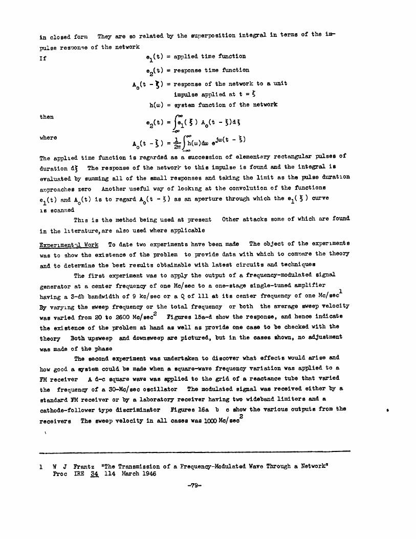
in closed form They are so related by the superposition integral in terms of the im-
pulse resoonse of the network
If el(t) = applied time function
e 2 (t) = response time function
A (t - ) = response of the network to a unit
impulse applied at t =
h(w) = system function of the network
then
e 2(t) = ( ) Ao(t - )dt
where Aot- ) = (w)dw e j wU (
The applied time function is regarded as a succession of element8ry rectangular pulses of
duration d The response of the network to this impulse is found and the integral is
evaluated by summing all of the small responses and taking the limit as the pulse duration
aoproaches zero Another useful way of looking at the convolution of the functions
el(t) and A o(t) is to regard Ao(t - 5) as an aperture through which the el( ) curve
is scanned
This is the method being used at present Other attacks some of which are found
in the literature,are also used where applicable
Experiment-l Work To date two experiments have been made The object of the experiments
was to show the existence of the problem to provide data with which to comonare the theory
and to determine the best results obtainable with latest circuits and techniques
The first experiment was to apply the output of a frequency-modulated signal
generator at a center frequency of one M/sec to a one-stage single-tuned amplifier
having a 3-db bandwidth of 9 kc/sec or a Q of 111 at its center frequency of one Mc/sec
By varying the sweep frequency or the total frequency or both the average sweep velocity
was varied from 20 to 2600 Mc/sec 2 Figures 15a-d show the response, and hence indicate
the existence of the problem at hand as well as provide one case to be checked with the
theory Both upsweep and downsweep are pictured, but in the cases shown, no adjustment
was made of the phase
The second experiment was undertaken to discover what effects would arise and
how good a system could be made when a square-wave frequency variation was applied to a
FM receiver A d-c square wave was applied to the grid of a reactance tube that varied
the frequency of a 30-Mc/sec oscillator The modulated signal was received either by a
standard FM receiver or by a laboratory receiver having two wideband limiters and a
cathode-follower type discriminator Figures 16a b c show the various outputs from the
receivers The sweep velocity in all cases was 1000 Mo/sec 2
1 W J Frantz "The Transmission of a Frequency-Modulated Wave Through a Network"Proc IRE 34 114 March 1946
-79-

(a) Over-all receiver bandwidth 70 kc/sec.standard communications receiver.
(b) Over-all receiver bandwidth 230 kc/sec,standard communications receiver.
(c) Wideband limiter and detector, laboratory model.
Figure 16. Response of a square wave of frequency.
Status. Calculations are in progress to check the present experimental results. Furtherexperiments and calculations, and possibly other theoretical approches are to be madenext. Types of excitation for which answers are desired are:
(a) Sudden change of frequency from one value to another.(b) Linear change of frequency from one value to another.(c) Sinusoidal frequency modulation.
These excitations may be applied to any of several networks and they may begineither inside or outside of the network pass band and end either inside or outside of thepass band.
Networks of interest are:
(a) The ideal bandpass filter.
(b) Synchronous single-tuned circuits.
Following work on these networks,more general cases will be considered.
-80-
I