IU'OTT BUILDING, DAYTON, 2, OHIO AU-zero friction or complete attachment at each interface, will on...
19
Reproduced by r %r-, u0 vicies T echnilcal Information agency.I J ~J~EiSER.VICE CENTER IU'OTT BUILDING, DAYTON, 2, OHIO AU- 11 ; la"d iLASSI FIED1
Transcript of IU'OTT BUILDING, DAYTON, 2, OHIO AU-zero friction or complete attachment at each interface, will on...

Reproduced by
r %r-, u0 vicies T echnilcal Information agency.IJ ~J~EiSER.VICE CENTERIU'OTT BUILDING, DAYTON, 2, OHIO
AU-
11
; la"d
iLASSI FIED1

"OFFICE OF NAVAL RESEARCH
Contract N7onr-35801
CD NR-041 -032
Techmical Report No. 85
COULOMB FRICTION, PLASTICITY, AND LIMIT LOADS
by
D. C. Drucker
GRADUATE DIVISION OF APPLI1ED MATHEMATICS
BROWN UNIVERSXTY
PROVIDENCE, H. I.
January, 1953
All -85/16

AlI-85
COULOMB FRICTION, PLASTICITY, ADM LIMIT LOADS 1
by D. C. Drucker 2
Abstract
Additional attention is given to the somewhat subtle
but extremely important difference between Coulomb friction and
the apparently corresponding resistance to plastic deformation.
It is shown that the limit theorems previously proven for
assemblages of perfectly plastic bodies do not always apply
when there is finite sliding friction. Theorems are developed
which relate the limit loads with finite Coulomb friction to the
extreme cases of zero friction and of complete attachment, and
also to the case where the frictional interfaces are "cemented"
together with a cohosionless soil.
-- -- -- -- ---- -----------------------------
1 The results presented in this paper were obtained in the courseof research sponsored by the Office of Naval Research underContract Nonr-35801 with Brown University.
2 Professor of Engineering, Brown University, Providence 12, R. I.

Sliding Friction vs. Plastic 'Resistance.
it was pointed out previously3 that the similarity
between the stress-strain relation for a rigid- or elastic-
perfectly plastic material and the force-displacement relation
for the Coulomb friction case, Fig. 1, may be misleading, The
essential feature may best be stated in mechanical-thermodynamic
terms for an assemblage of elastic-plastic bodies in equilibrium,
Fig. 2. If either the attachment is complete or if all coef-
ficients of friction are zero, no work can be extracted frnem
the bodies and any equilibrium system of forces acting upon them,
In other words, ther, is no way in which the bodies plus the
forces can act as an engine in this thermodynamic sense. They
can, however, if a coefficient of friction is finite3 .
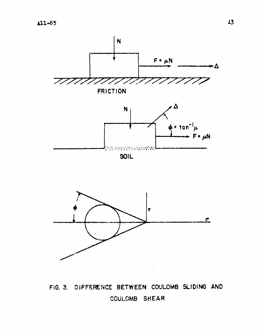
This point of view is made clearer and less abstract
by a comparison between Coulomb sliding friction and shearing
on a plane through a Coulomb cohesionless soil obeying the
generalized plastic potential laws, Fig. 3. The relation between
the normal vertical force N and frictional horizontal force
F in each case may be writtin as F = V.N. The displacement
picture, however, is fundamentally different The block in
the friction case slides in the direction of the force F. It
also moves up in the case of shearing of soil because of the
volume expansion which accompanies shear if the generalized plas-
tic potential relations are followed The displacement or
D..Drucker,, "Somre Implications of Work-Hardening and IdealPlastic.ty", Quarterly of Applied Mathematics, v. 7 (195O)pp. 411-418.
ID.C. Drucker and W. Pragcr, "'Soil Mechanics and Plastic Analysisor Limit Design", Quarterly of Applied Mathematics, v. 10 (1952)pp. 157-.165.

velocity vector makes an angle y with the horizontal, where-l
S= tan jL is the angle between the straight line env elope to
the limiting Mohrs circles and the negative d axis. Work is
done, therefore, against the downward force N. It is this
negative work, which prevents elastic-plastic bodies and the
system of forces acting on them from acting as an engine while
apparently similar frictional systems can.
Limit Theorems.
The two major limit theorems516 in a crude sense state
that an assemblage of elastic-perfectly plastic bodies, with
zero friction or complete attachment at each interface, will on
the one hand do the best they can to distribute stress to avoid
collapse and on the other will recognize defeat if any kinematic
collapse mode exists. This anthropomorphic approach is refined,
when geometry change is negligible, in the actual statement of
the theorems proved as:
1. Collapse will not occur if any state of stress can be
found which satisfies the equations of equilibrium and the boundary
conditions on stress and which is "below yield" at each point.
2. Collapse must occur if for any compatible flow pattern,
considered as plastic only, the rate at which the external forces
do work on the bodies equals or exceeds the rate of internal
dissipation.
3. Collapse takes place at constant stress so that strain
rates are purely plastic.----- -- -- -- -------------------- - - -- - -- -- -- -- -- ---
5 DC. Drucker H.J. Greenberg, W!. Prager1 "The Safety Factor ofan Elastic-Plastic Body in Plane Strain", Journal of A ppliedMechanics, v. 18, Trans. ASME, v. 73 (1951) pp. 371-378.
6 D.C. Drucker, H3J. Greenberg, W. Prager, "Extended Limit DesignTheorems for Continuous Media", Quarterly of Applied Mathematics,v. 9 (1952) pp 381-389.

All-85 4
Now suppose that the coefficient of friction is finite
and non-zero on at least one of the interfaces S of Fig. 2,
Is the system still intelligent enough to distribute the stress
to avoid collapse, and are the theorems still valid? Trouble
immediately appears in the upper bound Theorem 2. The rate of
internal dissipation cannot even be calculated in all cases because
frictional dissindtien is not determined uniquely by the flow
pattern. It dcpcnds not alone upon relative displacement rates
but also on the normal pressure on the frictional interface a
quantity which will often not be known. This type of difficulty
does not appear in the lower bound Theorem 1. It might seem
plausible to assume that the theorem is valid with the additional
requirement that the state of stress not violate the friction
condition at the interface as well as staying below yield. A
simple example shows this hopeful intuitive approach to be in
error.
Illustrative Examiples.
Fig. 4 a represents two rigid blocks, the heavy horizontal
one is balanced on a rough lodge while the light small one is on
an inclined plane with friction angle y and inclination a. The
contact surface between the blocks is at a slightly flatter angle
P than the plane and will be considered frictionless. There need
be no force between thŽ blocks and yet a largo force N could be
carried between the blocks without violating equilibrfumFig. 4b.
If y > a-P , such a force is stabilizing. Clearly, howevor,
if a > p the block will slide down the plane and no stabilizing
force will hc developed. On the other hand, if the sliding was
really plastic shearing as for a soil, then the incipient velocity

vector V would noint away from the inclined plane at an angle
q as in Fig. 4c. The large block would have to lift up and the
force N would indeed be mobilized to prevent sliding down the
plane. A modified Theorem 1 is thus seen to be improper for
the friction case but is againverified for the "plasticity"problem.
The problem of Fig. 4 might seem tricky and exceptional
because the little block is not really confined by the large one
and because the bodies are rigid. A more elaborate example is
probably needed to demonstrate the point properly. The punch or
equally well the uniform pressure example of Fig. 5 has special
dimensions to avoid calculations but is otherwise a good repre-
sentative plane strain problem. The interface UMNW between
the upper arch-shaped block and the lower support is supposed to
have an extremely large but finite friction angle. The yield
stress in shear will be called k and either the Mises or Tresca
yield condition is employed.
Fig. 5a shows a discontinuous stress solution passing
through the interface as though the two bodies were one. This
07is the often used 300 wedge solution slightly modified7 . In the
equilateral triangle region ABC the principal stresses are com-
pressivo and of magnitude 3k in the vertical direction and k
horizontally. In the sloping region BCDE the stress is 2k
parallel to BE and zero in the perpendicular direction. Region
DFE has principal stresses +k and -k. The shearing stress,
if any, and the normal traction on the planes of discontinuity
Yp. G. Hedge and W. Prager, "Theory of Perfectly Plastic Solids",John Wiley & Sons, 1951, Section 26.

All-85 6
BC, DE, HE, HD are continuous across the planes.
Both compressive and shearing tractions d and t in
magnitude which are easily calculated, will act on the interface
U14NW. The coefficient of friction V is assumed large enough
so that T<ULo. Therefore, the stress field of Fig. 5a multiplied
by a number ever so slightly less than unity will be "below yield"
everywhere and does not violate the friction condition. The total
force P per unit dimension perpendicular to the paper can be
made as close to 3kb as desired.
The question of whether or not the bodies are able to
adjust themselves in this static manner is answerdd by the possible
discontinuous rigid-block kinematic collapse pattern, Fig. 5b.
Block ATB is taken to more vertically downward with velocity
V requiring ATMU and BTNW to move at 45 with velocity V/iVr
so that separation occurs on MU and NW. Block MTN is
staticnary. The velocity discontinuity on the surfaces of sliding,
BTM and ATN each of length bV2, is V/Ir. The rate of energy
dissipaticn per unit perpendicular dimension is just
2-C , oe4 • W/ff) = 2kbV because in this permissible virtual
displacement pattern there is separation along the friction surfaces
MU and IW and they contribute nothing. Equating the rate of
work of the external forces PV to 2kbV gives the upper bound
and in this case correct result for Fig. 5, P = 2kb, and not
3~ h.
The intuitive limit theorem on the inherent intelligence
of the material is thus seen to be incorrect for finite and non-
zero friution. Again, substitution of an elastic-plastic "soilt
for the Coulomb friction interface fixes matters. Surfaces MU
and MiN do increase the energy dissipation and the value 3kb
Al1-85 7
is a proper lower bound if the angle q is large enough.
It might be thought that the separation counter-examples
given in this section are unfair. However, it is precisely
the freedom in the friction case to slide with an arbitrary
normal stress on the surface of sliding and therefore an
arbitrary dissipation which prevents the application of the
"intuitive theorems". Sliding at zero normal stress and actual
separation are essentially the same. An angle of 1+5 instead of
44 0in Fig. 5 would not really change the result.
Friction Theorems.
The question now arises as to what can be said about
limit loads for assemblages of bodies with frictional interfaces.
Two theorems seem intuitively obvious;
A. Any set of loads which produces collapse for the condi-
tion of no relative motion at the interfaces will produce
collapse for the case of finite friction. No relative
motion is a more inclusive term than infinite friction
because separation is not permitted.
B. Any set of loads which will not cause collapse when all
coefficients of friction are zero will not produce
collapse with any values of the coefficients.
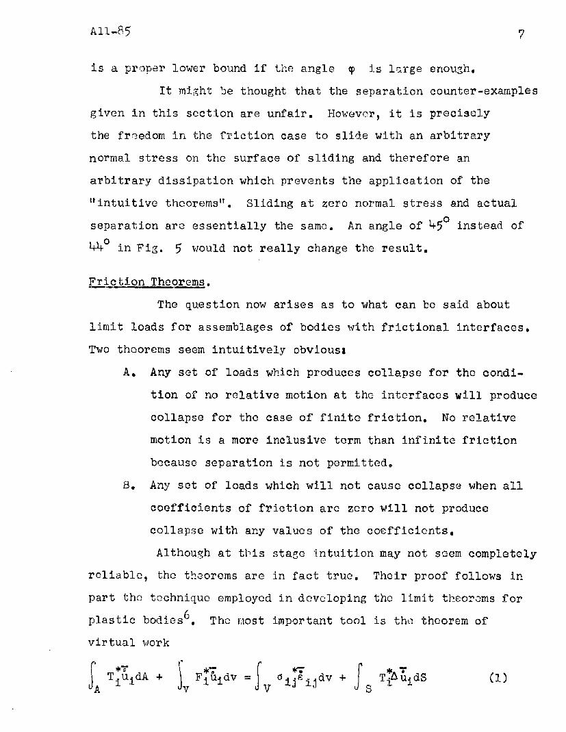
Although at this stage intuition may not seem completely
reliable, the theorems are in fact true. Their proof follows in
part the technique employed in developing the limit theorems for
plastic bodies6 The most important tool is the theorem of
virtual work
A TiudA + ý i 4uijv =I 0ijSij dv + I TiAuidS

All-8 5 8
8in which the sumnation convention is employed8. There is no
necessary tie between the equilibrium system of surface tractions* *
Ti, stresses oij, and body forces Fi, and the compatible
system of velocities ui, strain rates EiJ and velocity dis-
continuities A ui. The surface area A of the assemblage of
bodies of volume V does not include the frictional interfaces
S. For convenience of description, the velocity will be assumed
continuous except across S. The term T f
discontinuities in the material is omitted but this does not
actually restrict the generality of the result. 5 ' 6
Use will also be made of the properties of the yield
surface f(djA) = k2, Fig. 6. The rate of dissipation of energy
per unit volume, D = i P is uniquely determined by the
plastic strain rate P The "vector" i Fig. 6, is normalip. s a
I
nJ
"
to the yield surface at a smooth point or lies between the normal
to the surface at adjacent points to a vertex or corner. Further-
more, the surface is convex so that the dot product of the pla3tic
strain rate "vector" with any stress vector to a point OCj inside
the surface, f(dij,) < k2, cannot be as large as D.
- ) * p(2
Ej < D j
N NTo prove Theorem A, assutme that a set of loads Ti, F1
produces collapse when all relative motion is prevented at the
interfaces S (bodies welded together). This type of composite
body can be analyzed by the established limit theorems which state
A TidA + vFiuidv > S ijdv (3)
Reference 7, Chapter 8, As an examule,
0 d ij *0x x + yC + + Uxy~xy + T yz~yz +zxZXLijsj YX~ , Z 4, XYX Y y ZY

9IAlI-835~ 9
•Nand lJ is purely plastic,
Ni (elastic) = 0 (4)
For Theorem A to be false, there must exist some equilibrium
state of stress d J such that f(ojiJ ) < k2 . Using the virtual•N • N
work Equation (C), with uij siJ as the compatible state,
• ATI•dN' N + F dlvN. =I A" Nidv + TIAAu ds()
i i I i % - 'jA v 1 F v a A
However, Nu = 0 because the velocity solution represents noA' N" N
relative motion at S and, from Inequality (2), d < J lJ
Equation (5) is, therefore, in contradiction to Inequality (3)
and Theorem A can not be false.
The proof of Theorem B starts from the given set of0 0 0
loads Ti, Fi and stresses 0, which do not cause collapse
with z = 0. Next suppose that collapse can occur for L> 0
ýB B 4with a collapse field uD, ý, AB and stress field dm B
Virtual work Equation (1) becomes
F 9 Tr~d +ý 0j B~~v J a 0 OB' A + v v i ii J5 TituidS (6)
and the collapse condition is
TiuidA + FiŽUiV > Fij1 1dv + T TiuidS (7)A v v fS
Conditions (6) and (7) are incompatible and Theorem B cannot be
BO B O> B B "Bfalse because (i5sij > Pijil, Titui is a frictional dissipa-
tion and, therefore, zero or positive, and TAui is zero or
negative. The last statement follows from the fact that Ti
is normal to S at each point and is oomprcssive while AL? isis

Al1.-85 10]
a relative tangential displacement, and possibly a separation as
well, but not an overlap.
"The friction theorems A and B have thus been proved for
all stable convex yield functions. They occasionally enable the
limit load to be computed quite precisely for finite non-zero
friction. The well known two dimensional punch problem for a
Prandtl-Reuss or a Mises material provides such an example. Two
solutions are available for upper bound computations. One by
Prandtl 9 Fig. 7a, contains a rigid region which acts as an ex-
tension of the punch; there is no relative motion between the
punch and the contact area. The other by Hill 1 0 , Fig. 7b, assumes
zero friction and appreciable slip does take place. Both solu-
tions give the same answer for the average pressure, p = (2+n)k
Vkre k is the yield strcss in shear. A lower bound solution
of 5k has been obtained 3. Therefore, the limit pressure is
between 5k and 5.14k for all possible values of the coefficient
of friction.
It will often be found, however, that Theorems A and
B do not provide very close bounds. The concept of the plastic
cohesionless soil interface, already discussed in considerable
detail, may then be of furthei help in the following theorem.
9L. Prandtl, "IUaber die Haerte plastischer Koerper", Nachrichtenvon der Koeniglichen Gesellschaft der Wissenschaften zuGoettingen, iiathematisbh-physil-alische Klasse (1920) pp. 74-85.
1OR. Hill "The Plastic Yielding of Notched Bars under Tension"uarterly Journal of Mechanics and Applied N-athematics, v.
(1949) pp. 4o-)-2.
R. T. Shield and D. C. Drucker, "The Application of Limit Analy.
sis to Punch Indentation Problems", to appear in Journal ofApplied Mechanics.

Al11-85 11
C. Any set of loads which wilil not cause collapse of an
assemblage of bodies with frictional interfaces,, will
not produce collapse when the interfaces are "cemented"
together with a cohesionless soil of friction angle 9 =
aretan o.
The proof of Theorem C follows essentially from the
observation that the state of stress in the friction case satisfies_ 2the conditions f(Oj3) < and If T poIat impending collapse.
A safe state of stress exists, therefore, for the soil case when
collapse aoes not occur in the friction problem.
Concluslons
The limit load for an assemblage of bodies with
frictional interfaces is bounded below by the limit load for the
same bodies with zero friction on the intcrfacGs. It is bounded
above by the limit load for no relative motion at the interfaces
and also by the limit load for the same assembla&. cemented at
the interfaces by a cohesionloss soil. Limit theorecis applicable
to those bounding problems do not apply generally,

AIJ.-3512
F F
W V'o, e) A0 'r -'0" 4 el .1 1 F1
FIG. i. APPARENT ANALOGY BETWEEN FRICTION AND PLASTICITY
GI
Fit-G. 2. AN ASSEMBLAGE OF 810DIES irN .QU~iLiEfrW%'mm
IN_
F &N
FRICTION
N
11 7ý11 ton p.
. . ..- _ .: .:4..'.'..'"*...:*:. '.*: . .. ____________ __________
SOIL
FIG. 3, DIFFERENCE BETWEEN COUJLOMB SLIDING AND
COULOMB SHEAR

"(b)
'NN
v soic()
V-/ FRICTION
FIG. 4. A COUNTER-EXAMPLE- RIGID BODIES

b 0 -6w/
I I ZERO \
IP
• v ,• : v(b)
FIG, 5, TWO D IMENS•ONA. PROBLEM WI:TH E•LASTIC,-PLASTIC
1B094ES (a)AN EQUILIBR•IUM .SO~iTION tb) A VEUOCITY (KINEMA~iC•SO.UTION INVOLIING SEH RATON

All .Till
i G I N1
/ I
FIG. 6. THE YIELD SURFACE
PUNCH 4
(a ) (b)FIG. 7. (a) PRANDTL AND (b) HiLL 50LUTIO.W TO PUNICH PROBLE2M

Reprodkmed bv
'armed Services Tech nical a formation opgen,DOCUMENT SERVICE CENTER
KNOTT BUiLDiNG, DAYTON, 2, OHIO
A n
CqASSlFIFBDA-F
11,,, Vfm
A mmso