ITP Metal Casting: Advanced Melting Technologies: Energy Saving ...

Design, Installation, and Field Verification of Integrated Active Desiccant Hybrid Rooftop Systems Combined with a Natural Gas Driven Cogeneration
Package
Final Report: Phase 6 Subcontract Number 4000032487
By John Fischer Director of R&D
SEMCO, Inc.
January 2008
Prepared by:
For OAK RIDGE NATIONAL LABORATORY Oak Ridge, Tennessee 37831-6285
Managed by UT-Battelle, LLC
For the U.S. Department of Energy

CONTENTS
1. Abstract............................................................................................................ 3 2. Background and Introduction ............................................................................... 4
2.1. Program objectives ......................................................................................... 4 2.2. The integrated active desiccant hybrid rooftop system (IADR) ............................... 5 2.3. The 230 kW gas driven engine cogeneration unit (GDE) ....................................... 7 2.4. The integrated total energy recovery wheel module (TER) .................................... 8 2.5. The opportunity provided by the Pepperell High School site................................... 9
3. System Engineering, Load Analysis and Equipment Evaluation ................................ 11 3.1. Site description and basic design scheme ......................................................... 11 3.2. Benefits of the combined engine driven/IADR system......................................... 14
3.2.1. Hybrid active desiccant system (IADR) with total recovery ........................... 14 3.2.2. High efficiency gas driven engine generator with heat recovery..................... 14 3.2.3. Controls, data trending, and remote monitoring.......................................... 17
3.3. IADR equipment selection and detailed load modeling ........................................ 18 3.4. Cogeneration unit development – load matching with the IADR systems ............... 19
4. Construction Phase – Installation of Equipment .................................................... 23 4.1. Installation of the IADR-cogeneration unit combination ...................................... 23 4.2. Piping the cogeneration waste heat to the IADR ................................................ 24 4.3. Gas piping to the cogeneration unit ................................................................. 25
5. Results of System Operation.............................................................................. 26 5.1. Summary of the IADR DOAS system performance ............................................. 26 5.2. Summary of the cogeneration package performance .......................................... 28 5.3. Impact of energy costs on cogeneration control scheme ..................................... 29 5.4. Overall system performance observed and trended............................................ 31 5.5. Energy savings advantages excluding cogeneration ........................................... 34 5.6. Energy advantages associated with addition of cogeneration ............................... 36
6. Comparison with a Conventional VAV Baseline System .......................................... 38 7. Additional Advantages of the Advanced IADR System............................................ 40 8. Conclusions and Recommended Future Work........................................................ 41 9. Acknowledgement ............................................................................................ 42 10. References ...................................................................................................... 43 Appendices ............................................................................................................... 45
2

1. Abstract
This report summarizes a research/demonstration project in which a new high school facility was designed and constructed to combine a custom built 230 kW cogeneration package with four integrated active desiccant rooftop (IADR) systems to serve as high-efficiency dedicated outdoor air systems (DOAS). The IADR systems were modified to include hot water coils to use the waste heat provided by the engine jacket water for desiccant regeneration during the peak cooling season and heating during peak heating conditions. Each IADR was coupled with a total energy recovery module for outdoor air preconditioning. These four DOAS serve variable air volume (VAV) air handling units, designed to handle the space sensible load requirements. The outdoor air dew point delivered by the DOAS is controlled based on the space humidity conditions in order to accommodate all of the outdoor and internal latent loads. At the direction of the owner, all systems at this site are packaged, vapor-compression heat pumps. This also includes the main VAV air handlers which are served by remote-mounted (split system), custom designed packaged heat pump condensing units. Extensive instrumentation was provided for all HVAC systems. Actual data is provided to show state points throughout the advanced HVAC system to summarize design performance at four separate outdoor conditions. The performance of the advanced system is compared to a conventional HVAC system to show the potential savings in energy consumption and peak demand.
The advanced “integrated energy systems” approach detailed in this report provides an effective roadmap for constructing and operating comfortable, healthy, energy efficient schools (and other facilities) that follow current ASHRAE recommendations and meet all code requirements. This report also discusses the challenges and important design decisions that need to be made when selecting and installing a cogeneration system to serve active desiccant DOAS.
3

2. Background and Introduction
2.1. Program objectives Key Objectives The primary objective of this research project was to demonstrate the performance advantages of advanced “integrated energy systems” and “encourage further widespread adoption and implementation” of such systems. A further objective was to incorporate an advanced, integrated energy system into a conventional high school facility, where the level of design sophistication is typically limited and where budgetary concerns are high. This report summarizes a three-year project where a new high school facility was designed and constructed to combine a prepackaged cogeneration “prime mover” with prepackaged integrated active desiccant rooftop (IADR) systems to serve as dedicated outdoor air systems (DOAS). These systems serve main VAV air handling units, designed to handle the space sensible loads, since the outdoor air dew point delivered by the DOAS is maintained, as required, to handle all of the outdoor and internal latent loads. As directed by the school district, all systems must be packaged, vapor-compression heat pumps. The main VAV air handlers were served by custom designed packaged condensing units with all other systems (26 in all) being packaged, rooftop style units. The strategic scope of this research project is particularly important since in order to reach widespread commercial acceptance of integrated energy systems it is essential that the “prime mover” can be linked with packaged rooftop systems, and not just chilled water systems. This is true since approximately 90% of all commercial facilities use packaged equipment. Equally important to the primary mission of DOE, more than 85% of the energy consumed by commercial building HVAC systems can be linked to packaged equipment. Figure 1 provides graphic support for these conclusions.
Percentage of All BuildingsLess than 100,000 Sq.Ft.
0%
10%
20%
30%
40%
50%
60%
70%
80%
90%
100%
Packaged ACand HeatPumps
CentralChillers
Perc
ent o
f Bui
ldin
gs U
sing
HVA
C S
yste
m
Percentage of All BuildingsBased on Size
0%
10%
20%
30%
40%
50%
60%
70%
80%
90%
100%
Buildings Lessthan 100,000
Sq.Ft.
BuildingsGreater than
100,000 Sq.Ft.
Perc
ent o
f All
Build
ings
Cooling Energy Used by US Commercial Buildings
0%
10%
20%
30%
40%
50%
60%
70%
80%
90%
Energy Usedby PackagedAC and Heat
Pumps
Energy usedby ChillersPe
rcen
t Coo
ling
Ener
gy U
sed
by C
omm
erci
al B
uild
ings
Figure 1. Data showing the predominance of packaged equipment use in commercial buildings. Source: DOE 1999 Commercial Buildings Energy Consumption Survey Another specific objective of this research project was to demonstrate how school facilities can be designed and operated to comply with ASHRAE Standards 62, 55 and 90.1(1, 2,3) while
4

remaining energy efficient and cost effective. Previous DOE sponsored research (4 ) has shown that systems which actively control temperature, space humidity and ventilation can perform beyond the requirements of ASHRAE standards, and a key objective of this project was to add further support to these findings. Another key objective was to incorporate novel engineering solutions and equipment designs to substantially increase operating efficiency, and meet the point requirements for LEED certification. Yet another objective was to see if the final construction cost of this advanced HVAC system could be comparable with that of a more conventional HVAC system which would consume more energy and be less effective at controlling humidity and ensuring proper ventilation. Background A May 2003 ASHRAE Journal Article entitled “Report Card on Humidity Control”(4) summarized the findings of a comprehensive indoor environmental research investigation conducted for school facilities. Sponsored by Department of Energy (DOE) and completed in cooperation with the Georgia Tech Research Institute (GTRI) and Georgia State University, the investigation monitored the indoor environment in 10 Georgia schools over a period of two years. Among other observations, the researchers concluded that the schools which were equipped with conventional packaged HVAC equipment could not be operated with sufficient ventilation air to satisfy the recommendations of ASHRAE Standard 62. The study found that the outdoor air had either been shut off or significantly reduced in each of these schools in an attempt to improve humidity and address comfort complaints including poor indoor air quality. The researchers concluded that school designers needed an energy efficient, packaged HVAC system that could control temperature and humidity while continuously delivering a minimum of 15 cfm of outdoor air per student (4,5.6,7,8,9,10,15). That research provided the basis for the development of a novel integrated active desiccant – vapor compression hybrid rooftop (IADR) packaged unit specifically designed to meet this need. It has also been shown to operate as an effective DOAS or total conditioning system. DOE, through the Oak Ridge National Laboratory (ORNL), co-funded the development of the system and has tested it extensively at their Combined Heating and Power (CHP) test laboratory, where it has now operated for years conditioning that facility. The design subsequently earned ORNL and SEMCO a 2005 R&D 100 award for innovation (11). By modifying this IADR system to utilize the waste heat produced by a natural gas driven cogeneration unit for desiccant regeneration (cooling season) and heating, an effective DOAS system was developed to meet the needs of this research project.
2.2. The integrated active desiccant hybrid rooftop system (IADR) The IADR system integrates the benefits of active desiccant dehumidification with an advanced vapor compression heat pump cycle into a compact, hybrid packaged unit. It is designed to accommodate any percentage of outdoor air, so it can be applied as a DOAS (100% outdoor air) or as a total conditioning unit, processing both the outdoor and return air to a space. Both of these system configurations have been used for this research project. Due to the active desiccant wheel integration, the IADR will deliver air much drier than vapor compression alone. Figure 2 provides the basic airflow paths though the system. The IADR system brings outdoor (or return) air (1) through a fan (2) and DX cooling coil (3). Some of this air is passed through an active desiccant wheel (4) while the remainder is bypassed (5) to provide supply air (6) having the desired sensible heat ratio. A small amount of outdoor air (7) is heated to regenerate the active desiccant wheel, picking up the adsorbed moisture and vented to the outdoors (8).
5
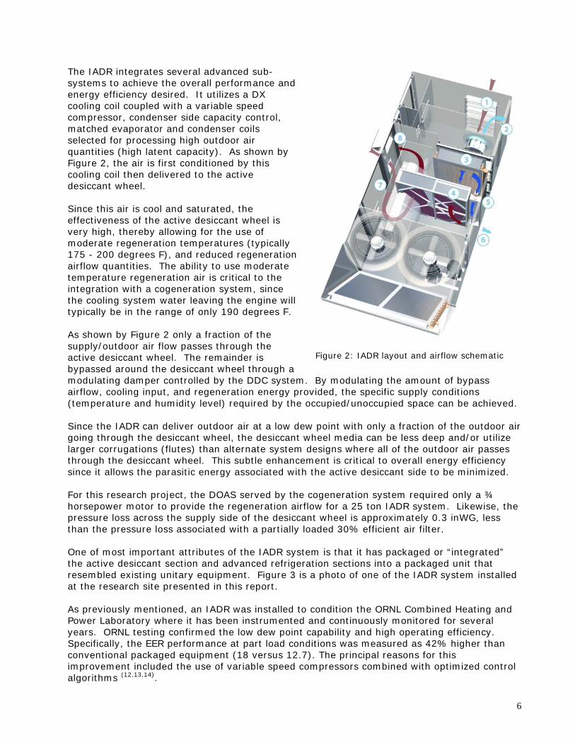
The IADR integrates several advanced sub-systems to achieve the overall performance and energy efficiency desired. It utilizes a DX cooling coil coupled with a variable speed compressor, condenser side capacity control, matched evaporator and condenser coils selected for processing high outdoor air quantities (high latent capacity). As shown by Figure 2, the air is first conditioned by this cooling coil then delivered to the active desiccant wheel.
Figure 2: IADR layout and airflow schematic
Since this air is cool and saturated, the effectiveness of the active desiccant wheel is very high, thereby allowing for the use of moderate regeneration temperatures (typically 175 - 200 degrees F), and reduced regeneration airflow quantities. The ability to use moderate temperature regeneration air is critical to the integration with a cogeneration system, since the cooling system water leaving the engine will typically be in the range of only 190 degrees F. As shown by Figure 2 only a fraction of the supply/outdoor air flow passes through the active desiccant wheel. The remainder is bypassed around the desiccant wheel through a modulating damper controlled by the DDC system. By modulating the amount of bypass airflow, cooling input, and regeneration energy provided, the specific supply conditions (temperature and humidity level) required by the occupied/unoccupied space can be achieved. Since the IADR can deliver outdoor air at a low dew point with only a fraction of the outdoor air going through the desiccant wheel, the desiccant wheel media can be less deep and/or utilize larger corrugations (flutes) than alternate system designs where all of the outdoor air passes through the desiccant wheel. This subtle enhancement is critical to overall energy efficiency since it allows the parasitic energy associated with the active desiccant side to be minimized. For this research project, the DOAS served by the cogeneration system required only a ¾ horsepower motor to provide the regeneration airflow for a 25 ton IADR system. Likewise, the pressure loss across the supply side of the desiccant wheel is approximately 0.3 inWG, less than the pressure loss associated with a partially loaded 30% efficient air filter. One of most important attributes of the IADR system is that it has packaged or “integrated” the active desiccant section and advanced refrigeration sections into a packaged unit that resembled existing unitary equipment. Figure 3 is a photo of one of the IADR system installed at the research site presented in this report. As previously mentioned, an IADR was installed to condition the ORNL Combined Heating and Power Laboratory where it has been instrumented and continuously monitored for several years. ORNL testing confirmed the low dew point capability and high operating efficiency. Specifically, the EER performance at part load conditions was measured as 42% higher than conventional packaged equipment (18 versus 12.7). The principal reasons for this improvement included the use of variable speed compressors combined with optimized control algorithms (12,13,14).
6

Figure 3. Photo of the IADR and total energy recovery module being installed at the research site The IADR system serving the ORNL lab was also fitted with a hot water coil and testing was completed to confirm the ability to regenerate the desiccant using waste heat from a cogeneration system. ORNL reports are available for this work (5, 12, 13, 14, 20). More specific details regarding the IADR systems as applied to this research site are discussed in the following sections of this report.
2.3. The 230 kW gas driven engine cogeneration unit (GDE)
The most significant challenge of this project was to find/develop a natural gas driven cogeneration package that contained all necessary components in an integrated unit, including an engine that was designed for continuous duty and could be serviced locally (a criterion critical to ensuring effective long term operation). After considerable research, it was determined that the product desired did not exist and that a partnership to produce an integrated cogeneration package was needed. With guidance from SEMCO, Deutz Energy AG, and their Atlanta distributor, WW Williams designed and produced the cogeneration package utilized as part of this research project. A new cogeneration product needed to be developed for several reasons. First, unlike common back-up generators, the cogeneration unit had to be designed to deliver continuous-duty prime power. The unit needed to utilize industrial, gas-fired engines with proven technologies. The Deutz TCG 2015 engine selected is used in critical duty applications, like cruise ships, and has been designed to be inherently reliable and low maintenance. An onboard, microprocessor control system constantly monitors all performance parameters, making real-time adjustments to achieve optimum operating conditions. In addition to the engine, controls, and cooling system, the cogeneration package needed to include the electrical generator, the hot water heat exchanger, the pumping system, the enclosure, the automatic transfer switch and other electrical panels needed. Specific product specifications for the cogeneration package are included as part of the appendix section. Photographs of the cogeneration package prior to the addition of the exterior enclosure are shown as Figure 4.
7

Figure 4. Photographs of both sides of the cogeneration package prior to the installation of the enclosure The Deutz TCG 2015 engine/WW Williams cogeneration unit provided the advantage of proven industry-leading engine performance with the highest available electrical (33.4%) and thermal (54.7%) operating efficiencies using an 1800-rpm, 322 horsepower V8 natural gas driven engine. Using only the engine jacket water provides a thermal efficiency of 36%. The high electrical and thermal efficiency associated with the engine jacket alone combined for a projected overall system efficiency of approximately 70%. The high engine jacket thermal efficiency was critical to the economical application of this product since, at this level it was determined that ample regeneration energy and winter season heating would be provided without the need for additional heat recovery from the engine exhaust stack.
2.4. The integrated total energy recovery wheel module (TER) The IADR systems have been designed so that total energy recovery (TER) can be added to the system as a standard option. This dramatically increases the overall system efficiency and reduces the amount of installed tons required by the IADR system. Also, during the heating season, the total recovery preheats and humidifies the outdoor air, reducing the outdoor air load so significantly that the heat produced by the cogeneration package was calculated to provide most of the additional heating necessary during normal operation on a typical heating day in North Georgia. The TER units are linked to the same modbus control network as the IADR systems and remote condensing units, enabling them to be operated as part of the overall system and to provide unoccupied and true economizer-based operation to optimize energy consumption. The control boards included within the IADR systems also serve the TER modules so that installation is simplified and the products are provided to the jobsite in a true “plug and play” format. The power requirement of the TER systems serving the IADR DOAS as well as all control power and pumping power (included in the cogeneration package) is provided by the cogeneration package. Figure 5 provides a photograph of the total energy recovery system integrated with the IADR DOAS prior to the connection of hot water piping. The hot water pipe connections to the loop served by the engine (to the right of the IADR) are not yet made.
8

Figure 5. Photograph of the total energy recovery module matched with each IADR system.
2.5. The opportunity provided by the Pepperell High School site
The new Pepperell High School selected for this research/demonstration project is located near Rome Georgia, approximately 50 miles northwest of Atlanta. This 200,000 square foot facility was designed for 1200 students and includes three main classroom wings, a media center, an administrative area, a cafeteria, a large performing arts center and a gymnasium. This school replaced an aging, existing facility and was constructed in multiple phases, on campus, during the active school year. Figure 6 is a photograph of the entrance to the newly constructed school.
Figure 6. Photograph showing the three classroom wings of the new Pepperell High School
9

10
This project provided an exceptional opportunity to showcase the integrated distributed energy system for numerous reasons, the most important being the timing of the project, the synergy of design objectives between the scope of this research project and those set by the end user, Floyd County Schools. The willingness of the project design engineer, other consultants and the commitment and vision provided by the Director of Facilities were also critical to the success of this project. Optimizing energy efficiency, indoor air quality and humidity control have been a top priority for years at Floyd County Schools. As reported by the Director of Facilities for the school district, the size of the building stock has doubled over the past 12 years yet the budget for energy has remained essentially the same. This was accomplished through high efficiency lighting retrofits, control system upgrades and by adding total energy recovery to the ventilation systems of existing schools. When planning for the construction of the new Pepperell High School, the design team was instructed to integrate progressive technologies such as premium efficiency lighting with motion detectors and LED exit signs. Since the greatest energy consumer within a school facility is the HVAC system, it was given the highest priority. Key HVAC design priorities set for the Pepperell High design team that were effectively addressed by the advanced “integrated energy systems” design approach offered by this research/demonstration project included the following:
(1) Outdoor air ventilation in accordance with ASHRAE Standard 62 – consistently delivered (2) Cooling season space relative humidity of 50% at 75 oF (15,16) and avoid saturated air in
ductwork (3) Use packaged direct expansion equipment – no chillers or boilers were desired (4) Minimize HVAC operating costs – ASHRAE Standard 90.1 (low demand/consumption) (5) Minimize classroom noise – goal to satisfy the ANSI S12.60-2002 sound criteria limit of
35 dbA (6) Minimize maintenance costs and optimize remote monitoring support (7) Maximize useable net interior floor area and architectural appeal of the final structure (8) Minimize any first cost premium over traditional HVAC designs.
As demonstrated by the original project design objectives set by Floyd County, this school district is a progressive, leading edge end user and, as a result, they proved to be a solid partner in this research project. They contributed both installation funds and services towards this project and were instrumental in its success The appendix section contains a letter outlining the participation commitment provided by the Superintendent of Floyd County schools.

3. System Engineering, Load Analysis and Equipment Evaluation
3.1. Site description and basic design scheme
The discussion included in this report summary will be primarily limited to the scope of this DOE co-funded research/demonstration project. However, to provide continuity, some results will also be provided for advanced systems that were purchased by the end user to enhance the overall project performance, which did not involve funds available as part of this research project. Site description As previously mentioned, the overall Pepperell High School project involved three main classroom wings, a media center, an administrative area, a cafeteria, a large performing arts center and a gymnasium, all of which have integrated advanced HVAC systems. Figure 7 provides a breakdown of the various school departments, including the approximate floor space involved, airflow required and associated HVAC details. Figure 7. Site summary with brief description of HVAC systems used for each space
School Area Served Area (sqft)
Supply (CFM)
Outdoor (CFM)
VAV (yes/no)
Equipment Utilized
Classroom Wing A (north and south) 41,835 45,764 12,000 Y (2) DOAH (1), (4)VAV AHUs, (4) VS Condensing units (2)
Classroom Wing B (north and south) 18,250 18,000 4,950 Y (2) TC Hybrid units (3), VAVClassroom Wing C (north and south) 41,835 54,470 11,175 Y (2) DOAH (1), (4)VAV AHUs, (4) VS Condensing units (2)
Media Center Wing B 7,350 6,000 900 N DOAS (3), VAV AHU, VS Condensing units (2)
Administration/Reception Wing B 7,650 5,000 420 Y DOAS (3), VAV AHU, VS Condensing units (2)
Atrium Wing B 5,875 5,200 930 N DOAS (3), VAV AHU, VS Condensing units (2)
Cafeteria and Kitchen 12,445 10,700 3,750 N TC Hybrid unit (4), one RTUBand and Choral 9,550 5,450 1,650 Y TC Hybrid unit (4), VAVPerforming Arts Center 16,450 18,200 7,500 N TC Hybrid unit (4), one RTUGymnasium and Locker Rooms 35,500 27,920 16,120 N (2) TC Hybrid units (4), multiple RTUs
Total 196,740 196,704 59,395
Notes: 1) Active desiccant - vapor compression hybrid system operated as a dedicated outdoor air system (DOAH). Includes total energy recovery, variable speed compressors and other novel enhancements for energy efficiency (see Figure 1 diagram) 2) VAV air handling units served by remote condensing units with heat pump integration using variable speed compressor option. 3) Total recovery - passive desiccant dedicated outdoor air system (DOAS) preconditioning to three AHUs energy recovery, variable speed compressors and other novel enhancements for energy efficiency (see Figure 1 diagram) 4) Active desiccant - vapor compression hybrid system operated as a variable volume system to handling all outdoor and space loads. Includes total energy recovery, variable speed compressors, etc. as shown in Figure 2 diagram (Advanced design 2). 5) RTU refers to conventional rooftop unit. In most cases, the RTUs are staged with the IADR systems and used only at times of peak occupancy.
The portion of the project that is covered by this research/demonstration project funding involves the application of four IADR units, operated as dedicated outdoor air systems processing approximately 4,725 cfm each, to deliver all ventilation air requirements to the main classroom areas of the Pepperell High School. These four IADR units were positioned behind the north and south classroom wings of the school facility. These four IADR systems and the associated total energy recovery modules were installed such that the power required to operate them could come from either the 230 kW Williams/Deutz cogeneration package or the power grid. The engine jacket hot water integral to the cogeneration package was first passed through a plate frame heat exchanger to serve the hot water loop, before being passed to the back-up dump radiator, also integral to the cogeneration package. This hot water loop was installed underground and run parallel to the back of the school, such that the loop could feed each of the four IARD units.
11

Figure 8 shows the basic layout of the classroom and administrative section of the school. Only one level is shown but two levels exist for each wing. As shown, the cogeneration package and two IADR units are located behind what is the southern most section of the classroom building designated as Wing C. Two additional IADR units are installed behind the northern most section, Wing A. Wing B is served by two larger IADR systems not served by the engine and are therefore outside of the scope of this DOE cosponsored project.
T EA CHERWORKR OO M
CEN TRALADM INI NIS TRAT I O NAND CO UN SEL ING
M EN SWO MEN S
WO M EN S
LOWER LEVEL MAIN BUILDING
MEN S
IS S
M EC HANI CAL
MEC HANI CAL
CAF ET ERI A
ARTF AM I LY & CONSUME R
SCI ENC ES
SCI ENC EPRE P
SCI ENC EPRE P
TEA CHERWO RKR OOM
SCI ENC E
SCI ENC E
SCI ENC E
SCI ENC E
SCIENC E SCI ENC E
SCI ENC E
ST ORA GE
MEN SWOM EN S
SCI ENC E
MEC H.
PRE P.
ERV .
DRA MA
TEA CHERWO RKR OOM
SP EDSP ED
SP ED
F &CS IN STRUC TIO N
O FF I CE
SS
SS
SS
SSSS
SS
SS
76 32S. F .
SP EDSP ED
Power GenCondenser
Condensers
(2) Rev 6000 (2) Rev 4500(2) Rev 4500(with recovery) (with recovery)(with recovery)
Note: Gymnasium, Band/choral, Cafeteria, Media Center and Administration also servedby Revolution or Recovery. Building details for these areas are not shown above.
Figure 8. Schematic showing the location of the cogeneration package and IADR units. Basic design scheme The fundamental design scheme applied to this project began with the “decoupling” of all latent loads from the main VAV air handling units. By dehumidifying the outdoor air volume to a low dew point, each IADR system, operating as a dedicated outdoor air system (DOAS), was able to remove the latent loads from both the outdoor and indoor air streams. The control system measured the dew point of the return air entering each main VAV system. Based on that value, the supply air dew point leaving the IADR was modulated (down to as low as a 40 oF dew point), to ensure the space humidity did not rise above a 55 oF dew point. The many benefits offered by this dedicated outdoor air system approach have been extensively reported by Fischer (7), Bayer (6), Mumma (16) and others. Each of the four IADR units operated as DOAS were also served by the cogeneration package such that, when desired, the “free heat” provided by the engine jacket could be used to either regenerate the active desiccant wheel during the cooling season or provide reheat to the outdoor air leaving the total energy wheel or heat pump coil during the heating season.
12

13
Since the IADR units are capable of being controlled to handle all latent loads, the main VAV air handling units operate with essentially dry, sensible only cooling coils. These main VAV air handling units were installed within indoor mechanical rooms and served by remote condensing units incorporating variable speed compressors and advanced controls to enable effective cooing and heat pump operation and facilitating variable airflow across the indoor coil. Cooling mode: When in the cooling mode, the outdoor air leaving the IADR units and delivered to the main VAV air handling units is dehumidified to a level that is dry enough to handle (1) the outdoor air latent load, (2) the humidity generated within the space by the occupants or moisture generating equipment and (3) any infiltration. The integrated DDC controls, part of each IADR unit, monitored the return humidity content from each classroom wing and then modulated the cooling capacity, regeneration energy and bypass airflow to achieve the supply air dew point required. In addition to handling the entire latent load, the IADR typically handles the sensible load associated with the outdoor air. Therefore, the preconditioned outdoor air is delivered to the return air duct feeding each classroom wing main VAV air handling system, at a temperature similar to that maintained within the occupied space, but at a very low dew point. Figure 17 provides a simple schematic to describe the design concept behind this advanced “integrated energy system”. Since the outdoor air volume is generally small relative to the total airflow volume required to cool the facility or space, the IADR system must deliver air at dew points much lower than are typically associated with conventional cooling systems. In this case, actual trended data confirmed that during the peak cooling season supply air dew points as low as 40 degrees F were required in order to maintain the relative humidity of the occupied space at 50%. Observed supply air dew point conditions around 45 degrees F were quite common. The supply air dew point conditions observed (and modeled) highlight the advantage of the IADR in that it can deliver air at very low dew point conditions while utilizing moderate leaving cooling coil temperatures since the important “low end” dehumidification is accomplished by the active desiccant wheel. As discussed in more detail in the Results Section, the IADR also has the benefit of offering the school an effective unoccupied mode (humidity control at reduced ventilation rates) and true economizer operation that is enthalpy based, which helps to reduce energy consumption. Heating mode: During the heating mode the total energy recovery wheels provide most of the preheat needed for the ventilation air volumes. Further heating is provided by either integral heat pump operation included in each IADR and/or by the hot water reheat coil, integral to the IADR units and served by the cogeneration package. Custom control algorithms were used to provide as much building heat as possible by the IADR units to minimize the use of the electric resistance heat installed in the VAV boxes serving the individual classrooms.

14
3.2. Benefits of the combined engine driven/IADR system
The effective combination of the IADR and cogeneration system provides better overall performance than if the two were applied individually. Without an effective use for the waste heat byproduct associated with on-site power generation, the system efficiency is unattractive to most facilities that have reliable power from the grid. The IADR provides an attractive use for this waste energy, increasing the overall system efficiency by replacing the direct fired gas burner option with a hot water coil. 3.2.1. Hybrid active desiccant system (IADR) with total recovery
As previously mentioned, the ability of the IADR to operate as an energy efficient DOAS, delivering outdoor air dehumidified to low dew point conditions allows the supply air temperature leaving the VAV unit to be modulated to meet the sensible load requirements of the individual classrooms (higher leaving coil temperatures possible), rather than being lowered in order to satisfy the need for dehumidification. Removing all humidity loads with the dedicated outdoor air system avoids the “over-cooling and reheat” approach common to most VAV systems, greatly improving the overall system efficiency. It also complies with ASHRAE Standard 90.1 which recommends against using reheat from new energy sources for humidity control purposes. A contrast in energy use between the Pepperell HVAC design shown in Figure 17 (advanced design) and the baseline (conventional) approach shown in Figure 26 highlights the importance of following 90.1 recommendations. During the heating season, the energy efficient heat pump operation or hot water reheat coil served by the cogeneration package is operated to handle much of the heating load. This provides significant energy savings since the heat is otherwise handled by the electric resistance heat located in the VAV boxes. The IADR dedicated outdoor air systems with total energy recovery modules also measure and deliver a constant supply of preconditioned outdoor air to the VAV air handling units. This approach ensures that even as the airflow supplied by each main VAV air handling unit varies from its high of approximately 11,000 scfm (during peak cooling) to a low of 3,000 (peak heating), the amount of outdoor air delivered to the occupied spaces complies with ASHRAE Standard 62 recommendations. The benefit of supplying proper ventilation rates to the building have been quantified by results of a research study confirming very good indoor air quality, as discussed in Section 7. During unoccupied times, the outdoor air intake is reduced and return air is conditioned by the IADR, using primarily the active desiccant wheel with low energy use, to maintain an upper limit to the space humidity level. Monitoring system operation confirmed that this IADR DOAS approach was able to operate in a manner that met all of the design goals set by the owner and listed in Section 2.5 of this report.
3.2.2. High efficiency gas driven engine generator with heat recovery The novel design approach used for this research/demonstration project segregates the natural gas driven cogeneration package from the power grid. The power produced by the cogeneration package was designated to power four IADR systems serving as DOAS for the two main classroom wings. Details related to this design decision are discussed in Section 4.0.

The integration of the natural gas driven cogeneration package offers significant benefits to the Pepperell High School during both high cooling/dehumidification and high heating conditions. As shown in Figure 9, the custom built cogeneration package, based upon the Deutz high efficiency engine, offers a high electrical efficiency (33.4%) and a high thermal efficiency (36%) using only the heat produced by the jacket water. The projected 69.4% overall system efficiency is far higher than the typical electrical system efficiency of the commercial distribution grid. As a result, provided that there is a productive use for the waste heat when the engine is in operation, and that the cost of gas to the end user is not at an elevated level, the overall energy bill to the end user is less when the IADR – cogeneration combination is operated.
W.W. Williams - Cogeneration SpecificationsDeutz CHP
Engine Generator Performance
15
Figure 9. Cogeneration specifications for the custom Williams/Deutz package. Cooling season advantages: Placing the load associated with the four IADR units and total energy recovery modules on the engine rather than the power grid during the peak cooling season reduces the connected load peak demand by approximately 145 kW. Removing this electrical load from the power grid provides a 21% reduction in the overall building electrical demand and a 37% reduction in peak electrical demand associated with the HVAC system. Like most school facilities, the Floyd County school district has an electrical rate package that includes a charge based on peak demand. Reducing peak demand results in a lower energy bill to the end user. In the case of this project, the impact is modest. In addition, during times of high humidity, the heat from the engine is well matched to the electrical load required by the IADR systems. All of the hot water generated is
Continuous Output at Unity Power (kW) 2 30 Mechanical Power (bhp) 3 22 Rotating Speed (rpm) 1 ,800 Actual Heat Rate (Btu/kWh) 1 0,204 Fuel Consumption (M Btu/Hr) 2 ,347
Actual Electrical Efficiency 33.4%
Nominal Flow rate (gpm) 1 20.6 Engine Inlet Temperature (deg F) 1 76.0 Engine Outlet Temperature (deg F) 1 90.0 Heat Energy (Btu/Hr) 8 44,875
Actual Thermal Efficiency 36.0%Overall Conversion Efficiency
Electrical plus Thermal 69.4%
Jacket Water Heat Recovery Potential

required for desiccant regeneration. During times of typical gas prices, this results in a further reduction in overall energy costs to the end user. This is discussed in more detail in Section 5.2. Figure 10 shows performance typical of the IADR units operating as DOAS at the Pepperell site. Outdoor air shown entering the unit has been preconditioned by the total energy recovery module. Essentially all of the available engine heat is used to deliver air at the desired dew point.
16
Input Bypass
2498 cfm OuputsOutdoor Air Mixed Air Exit Coil
Supply DX Tons Input
Lvg. DH DX Tons Output
Return Air Max Regen Input
Regeneration Supply Conditions
Supply Grain Level Latent Cooling Delivered
55 DegF5258 cfm 5258 cfm 55.5 DegF 64 grains79.8 DegF 79.8 DegF 98% RH 23.3 BTU/lb 4995 cfm 19.5 tons91.4 grains 91.4 grains 64 grains 73.0 DegF33.5 BTU/lb 33.5 BTU/lb 23.3 BTU/lb 46.5 grains
2498 cfm 24.8 BTU/lb 20.1 tons90 DegF28 grains
0 cfm 26.2 BTU/lb 143,017 BTU/hr76.0 DegF62.7 grains 114 DegF28.0 BTU/lb DX Coil 105 DegF 178 DegF 85 DegF 73.0 DegF
130 grains 130 grains 46.5 grains174 grains 1374 cfm 45.3 Dew Point F
51% RH46.5 grains Btu Input 143,017 BTU/hr 23.6 tons
0 grains1637 cfm
50% 0.2Bypass % SHR
Regen Out Regen In
Figure 10. Example of projected cooling season performance for IADR DOAS Heating season advantages: The quantity of heat provided by the engine during a heating day for this project is approximately 543,000 Btu/hr (jacket water only) as shown in Figure 13. The system design diverts this heat (hot water) directly to the DOAS supply air stream via a reheat coil mounted in the outlet duct of the IADR. This waste heat source is particularly beneficial during the heating season since it offsets approximately 234 kW of peak electrical demand that would otherwise be consumed by the electric reheat coils mounted within the individual VAV boxes. One of the interesting and unexpected findings from this research is that the typical VAV system installed in schools, particularly in the southern US, uses electric resistance heat with the VAV boxes for final space heating. It is also typical to use a night/weekend setback temperature in an attempt to reduce energy consumption. Building performance trending confirmed that during cold weather, when the global setback space temperature was raised from 65 degrees F to 72 degrees F, essentially all of the electric reheat in the building (approximately 500 kW) was energized for hours in order to bring the cold building mass up to the occupied set point. One of the early modifications to the control system was to send a wintertime supply reset temperature to both the main VAV systems and the IADR DOAS to deliver air as warm as possible during this “warm up” period and during very cold days in an attempt to minimize the use of the electric resistance heat. The heat pump integration into both the main VAV air handling units and the IADR systems provides a far more effective (350% more) heating source than the resistance heat included within the VAV boxes.

17
During such times, all of the heat generated by the engine can be effectively used, coupled with the heat provided by the heat pumps and thereby mitigating the impact of the “defrost cycle” during very cold days. This offers considerable energy savings to the owner. 3.2.3. Controls, data trending, and remote monitoring The main control system provided for this project is likely one of the most comprehensive ever provided to a school facility. A main server installed at the Floyd County headquarters facility monitors all of the advanced HVAC systems provided for this project (approximately 37 pieces of equipment). Each piece of equipment has been fully instrumented, with approximately 75 state points being provided for each system. Most of these state points have been set up with a trending capability. All of the programs necessary to operate the individual systems, main air handling units and remote condenser/heat pump units were written by SEMCO. A private virtual private network (VPN) connection was set up early on to allow remote access by multiple users outside of the school district and has allowed for unlimited access, data collection and program updates/modifications. Graphical windows created by SEMCO for the IADR units and other systems have allowed the end user to better understand the operation and function of each system. Alarm points integrated into the program alert the end user if any of the systems are not performing as desired. In addition to the numerous sensors installed for system monitoring, a modbus communications network is connected to all of the frequency inverter drives used by the IADR systems, main air handling units and remote condenser/heat pump units. This communication network allows access to a long list of additional important information, ranging from fault monitoring to load details. The level of system performance monitoring provided by this advanced control/data acquisition system proved to be one of the most important aspects of this research project. Particularly useful to this project was the energy-use monitoring capability provided by a modbus communications network which reports the real-time electrical use of most of the individual components used within the advanced HVAC system. An example of important modbus information provided by the program logic is provided as Figure 11. This advanced control system was of particular interest to the Pepperell facilities manager since very few buildings are instrumented, trended and analyzed after construction to see how the HVAC designs are actually performing. In this case, the facilities manager for the Floyd County School District was anxious to “see the data” resulting from this investigation so that it could be used to guide the direction of future HVAC designs. The data provided by the control/monitoring system has been condensed to provide the performance snapshots contained within Sections 3, 5 and 6 of this report.

Supply Fan - 4.1 KWCompressor - 6.7 KWOutdoor Fan - .5 KW
Energy Summary: (Heating Mode)
Supply Fan - 4.1 KWCompressor - 6.7 KWOutdoor Fan - .5 KW
Energy Summary: (Heating Mode)
Figure 11. Sample electrical consumption data provided by the main control system Figure 11. Sample electrical consumption data provided by the main control system
3.3. IADR equipment selection and detailed load modeling 3.3. IADR equipment selection and detailed load modeling Data summarized in Figure 17 was used to calculate the actual sensible and latent loads for one classroom zone at the Pepperell School facility. These actual loads were compared to those calculated for the classroom areas using the ASHRAE recommended guidelines discussed in chapters 29 and 30 of the 2001 Fundamentals Handbook (17). These calculations reflected a well constructed, tight facility using high efficiency lighting. A value of 200 Btu/person was used to estimate the latent load associated with the occupants, reflecting moderate activity as recommended by the DOE sponsored IAQ research findings (4,6).
Data summarized in Figure 17 was used to calculate the actual sensible and latent loads for one classroom zone at the Pepperell School facility. These actual loads were compared to those calculated for the classroom areas using the ASHRAE recommended guidelines discussed in chapters 29 and 30 of the 2001 Fundamentals Handbook (17). These calculations reflected a well constructed, tight facility using high efficiency lighting. A value of 200 Btu/person was used to estimate the latent load associated with the occupants, reflecting moderate activity as recommended by the DOE sponsored IAQ research findings (4,6). The results of this analysis are summarized in Figure 12. As shown, the calculated loads agree quite well with the actual loads that existed. This confirms that following recommendations of the ASHRAE Fundamentals handbook provides an accurate estimate of building loads.
The results of this analysis are summarized in Figure 12. As shown, the calculated loads agree quite well with the actual loads that existed. This confirms that following recommendations of the ASHRAE Fundamentals handbook provides an accurate estimate of building loads. It is useful to note that some commercially available modeling programs do not accurately reflect the internal latent loads associated with occupants and infiltration, and they often over estimate the internal sensible loads. The artificially high sensible heat ratio results in schools having the high humidity conditions and low ventilation rates reported in the 2003 ASHRAE Schools Humidity article (4).
It is useful to note that some commercially available modeling programs do not accurately reflect the internal latent loads associated with occupants and infiltration, and they often over estimate the internal sensible loads. The artificially high sensible heat ratio results in schools having the high humidity conditions and low ventilation rates reported in the 2003 ASHRAE Schools Humidity article (4).
18

Outdoor ConditionsActual (1) Modeled (2) Actual Modeled Actual Modeled Actual Modeled
Internal LoadsNet Sensible 234,796 228,471 135,331 137,065 -69,138 4,176 -175,401 -192,776
Net Latent 102,279 98,106 76,866 78,957 57,932 56,326 10,368 30,214Outdoor Loads
SensibleLatent
Total LoadsNet Sensible 300,114 293,789 145,537 147,271 -132,731 -59,417 -362,681 -380,056
Net Latent 307,911 303,738 211,812 213,903 109,342 107,736 -18,549 1,297Sensible Heat Ratio (SHR) 0.49 0.49 0.41 0.41
65,318134,946 51,410 -28,917205,63210,206 -63,593 -187,280
Actual Zone Loads (Measured Data) versus Modeled Zone Loads88 oF/132 grains 77 oF/109 grains 62 oF/82 grains (3,4) 34 oF/24 grains (3)
Notes: 1) Actual loads reflect measured values based on airflows and psychometric conditions at the site and shown in Figure 3. 2) Modeled loads based on building design characteristics and ASHRAE recommendations (2001 Fundamentals Chapters 29 and 30) 3) Reflects data collected during morning warm-up following night-setback, thermal storage of building mass evident in actual sensible load 4) Windy day resulting in higher infiltration rates than modeled for sensible and latent loads 5) Values shown above are for one zone consisting of the upper and lower level of the northern half of wing A, 18 classrooms approximately 21,000 sqft. 6) Load modeling assumes 250 Btu/person sensible and 200 Btu/person latent (as per May, 2003 ASHRAE paper) using a total of 212 occupants for each Zone 7) Infiltration assumes a very tight building, .1 cfm/sqft of exposed wall area. Low wind condition. Lighting load reflects the actual use of 1.125 watts per sqft.
Figure 12. Load analysis – actual documented loads vs. modeled loads (Btu/hr) These loads confirm the high latent load fractions (low SHR) which challenge designers of school facilities, necessitating the use of “over-cooling” with costly zone reheat to control space humidity with conventional HVAC systems. The alternative is to accept high space humidity levels and/or reduce ventilation, sacrificing IAQ in an attempt to reach comfort. This common compromise has been reported by Fischer, Bayer, Downing and others (4,5,6,7,9,10,16,18,19). A comparison of the advanced systems demonstrated by this project with a conventional VAV system is discussed in Section 6 of this report to summarize the challenges associated with low sensible heat ratios and high outdoor air fractions.
3.4. Cogeneration unit development – load matching with the IADR systems
The objective of the design scheme used for this project is to operate the cogeneration package as often as justified by current energy costs and design conditions. As a result, it was critical to apply an engine designed for continuous duty. The engine needed to be natural gas driven, offer both a high electrical and thermal efficiency, be prepackaged with the heat exchanger, and meet the required noise and emissions criteria. Finally, the size of the engine needed to meet or exceed the power requirements of the project. After an extended investigation of products available at the time of this proposal, it became clear that the desired engine driven cogeneration product did not exist and, therefore, would have to be developed. After evaluating all of the available options, W.W. Williams was chosen as the partner best positioned to produce the cogeneration package needed for this research project. Williams exhibited the experience desired, had a high interest in developing gas driven cogeneration packages, could provide the service required and were located within approximately 2 hours from the Pepperell project site. Williams recommended the use of the Deutz engine. The engine is considered one of the highest quality engines available, is designed for continuous duty and has a proven track record of successful operation using natural gas. Details of both the Deutz engine and the Williams cogeneration package are included as part of the appendix section.
19

20
A listing of the major components used to produce the Williams 230 kW continuous duty cogeneration package is as follows: − 4 cycle natural gas engine (Deutz TCG 2015 V8, Natural Gas Engine, 1800 RPM) − 480Y/277 Volt Marathon Brushless permanent magnet (PM) excited generator − Engine and Generator mounted on a structural steel base and connected to the
CHP Module with steel spring isolators − Fully adjustable electronic isochronous governor (frequency reg. +/- .25%) − Automatic Transfer Switch (ATS) − TEMBASIC Digital Auto-Start Control panel with Alarms and Shutdowns − Critical Grade, Low profile Exhaust Silencer with flex Connector − Plate and Frame Jacket Water Heat Recovery Unit − Unit Mounted Dump Radiator with Pre-Wired Electric Fan − Hot Water Service Pump Mounted within the Enclosure − Outdoor Enclosure with Sound Attenuation − Easy Access Doors − 480Y/277 Volt 3 Phase House Panel Pre-wired − Engine jacket water heater, 2500 watt, 480 volt with isolation valves − Battery System, 10 Ampere float/equalize, with alarm contacts, 120 VAC
Installed − Batteries, Maintenance Free lead acid, 1150 CCA, 24 VDC, with battery rack
Based upon the detailed load analysis and IADR equipment selection, it was determined that an electrical load between approximately 145 kW and 180 kW would be required. The variability in the load required was driven by the ventilation rate and therefore the size and number of IADR systems required. Since the design of the cogeneration system needed to be designed/manufactured prior to the completion of the HVAC final design by the consulting engineer of record, an engine with the capacity of at least 180 kW had to be selected. Deutz offers two different gas fired engines that were potential candidates. One was a six cylinder version that produces 172 kW and the other was eight cylinder version that produces 230 kW. Based on recommendations of the engine supplier, the 230 kW version was chosen. Figure 13 shows the final load profile on the cogeneration package. The “as built” design required less outdoor air and therefore fewer tons than originally thought. This presents some challenges as it relates to loading the engine, and it is clearly preferred to have a firm assessment of this load prior to selecting an engine. It simply could not be done in this case. Fortunately, there was not a significant impact on the final outcome since the overall cogeneration efficiency only drops 2 percentage points when the engine is modulated from full load down to 50% of the full load condition.

Sub-System Load Matching Analysis Per System Total
IADR with total energy recovery option
Electrical Load Matching
Total Electrical Load Required at Peak 145.5
Total Electrical Load Provided at Peak 145.5(modulated as needed)
Thermal Load MatchingCooling Season
640,000 btu/hr
625,000 btu/hr
Heating Season
543,000 btu/hr543,000 btu/hr
Conclusion from analysis: Match between IADR and Williams engine
Outdoor air ventilation requirements for IAQ 5035 cfm 20,140 cfm
4 required
Revolution KW required including recovery module 46 KW 139 KWEngine power requirement (pump and miscellaneous) 6.5 KW 6.5 KW
WW Williams - Deutz CHP-230-480-HW 1 @ 230 KW
Revolution unit regeneration energy (average at design) 160,000 btu/hr
WW Williams engine (at 145.5 KW output)
Heating season preheat (at design) 136,000 btu/hrWW Williams engine (at 115 KW output)
Figure 13. Final cogeneration system – IADR load profile comparison As shown, under normal cooling season operation the IADR systems utilize approximately 63% of the total load from the cogeneration package. Most importantly, at this reduced load condition the jacket heat output from the engine provides a good match to that needed for desiccant regeneration. The same holds true for the heating season. Typically operated with one compressor running in the heat pump mode, the heating season demand of 115 kW provides enough heat output to supplement the outdoor preheat load as desired. On the coldest days, both compressors are called for, increasing the load on the engine and thereby providing more useable heat for building warm-up (as previously discussed). One of the recommendations to the owner may be to add an additional 30-50 kW of load to the cogeneration circuit in the future to increase the heat output during the cooling season, but this enhancement is beyond the scope of this project. Based on observations made thus far, the current loading appears effective and acceptable. Other key design decisions involved packaging, noise considerations and emissions ratings. The Williams cogeneration package was designed to be reasonably compact, and has a size similar to that expected for outdoor mounted HAVC equipment. The overall dimension of 72” W x 152” L x 132” H easily fit within the equipment area designated during the early design phase. Figure 15 provides a photograph of the cogeneration package along side other equipment serving the building. The enclosure included sound hoods over all intakes and internal attenuation. The engine exhaust incorporated a “critical grade” exhaust silencer. This design was effective in keeping the noise associated with the operation of the cogeneration package to a minimum and on par with that observed from the remote condensing units.
21

22
The emissions associated with the Deutz met all of the requirements of the Georgia Department of Natural Resources for air quality control Chapter 391-3-1 as designed, so no special modifications were required. Finally, the engine was served by the TEM basic control panel which is capable of modbus communications. Initially it was thought that this modbus communications capability would mesh seamlessly with the modbus network used to communicate between all other systems provided. Unfortunately, the modbus used by the engine manufactured in Germany is a different version of the modbus protocol with a different code language methodology, making field communications highly complex. This communications problem will be discussed in later sections of this report.

4. Construction Phase – Installation of Equipment
4.1. Installation of the IADR-cogeneration unit combination One of the major obstacles of on-site power generation is the inter-connection between the electrical grid and the engine. The design scheme used for this project eliminated this issue by providing the generated power directly to the IADR outdoor air precondition systems, total recovery modules and engine water pump, thereby isolating the engine from the power grid. This design approach proved effective since the combination of the IADR and total energy recovery units, during times of even moderate heating or cooling loads, resulted in a consistent power load on the cogeneration package. Since the IADR units are installed as DOAS, a disproportionate amount of the overall building electrical load is required of these “all outdoor air” units. This arrangement therefore provided an ideal location and placement for the cogeneration system, producing the energy/demand benefits mentioned in Section 3.2.2. It also allowed the engine to be located near to the units served thereby minimizing the ancillary costs of installation such as electrical distribution and piping. Grid Independent Packaged CHP System with Hybrid Dedicated Outdoor Air Systems
460V Power to IADR Hybrid andRecovery Units
Hot Water fromEngine Jacket Regeneration
andWinter Heating
23
(600,000 BTU/HR)
(1,590,000 BTU/HR)at 150 KW as applied
Packaged with Engine Jacket Heat Recovery
ev-4500 with FVR-7500
Natural Gas Input
Natural Gas Engine CHP IADR Hybrid with Total Recovery SEMCO R (typical of 4)
OutdoorAir
Figure 14. Simple schematic showing how the engine is coupled with the IADR systems. Figure 14 provides a simplified schematic showing how the cogeneration package is connected to the four IADR units served by the total energy recovery modules. A main power distribution panel, served by the automatic transfer switch (ATS) that is part of the cogeneration package, feeds all four IADR systems, recovery modules and the hot water pump serving the heat recovery loop. The ATS directs either engine power or grid power to these units based upon a signal from the main building control system.

Figure 15 is a photo showing the cogeneration package installed behind the C wing of the Pepperell project. Two additional IADR systems are located in a similar fashion behind the A wing of the school, approximately 200 feet from C wing.
Figure 15. Photo of cogeneration package installed behind the Pepperell School
4.2. Piping the cogeneration waste heat to the IADR After the cogeneration package, the cost of piping the heating and regeneration coils in each IADR system and the hot water loop was the next greatest cost associated with integrating the cogeneration system. All of the piping is run underground then brought up to the individual IADR systems. A circulation pump and plate frame heat exchanger located within the cogeneration package serves the hot water loop and is energized any time that the cogeneration system is operating. A dump radiator is installed within the cogeneration package as well, as a contingency for when the engine is operational but the load required by the IADR systems is not adequate. This seldom occurs. Figure 16 is the schematic drawing provided by C&M Engineering, the design consulting partner that was part of this project, showing the piping details employed for this installation. As shown, a three-way control valve is installed at each IADR to modulate flow to the coils. A diverter valve directs the hot water flow to either the regeneration coil or the heating coil as required, based on a signal from the DDC controller integral to the IADR system. Circuit setters were installed to allow for balancing the water flow to each system. The regeneration heating coils selected for the IADR systems utilize 5 rows and operate at low face velocities to allow the outdoor air stream temperature to be heated very close to the entering hot water temperature (180 oF). The supply air heating coils were sized to utilize only one row to minimize the air pressure loss while still providing very effective heat transfer.
24

Figure 16. Piping diagram for hot water loop serving each IADR system (regeneration and heating coils shown). This hot water loop is served by the engine jacket recovery loop.
4.3. Gas piping to the cogeneration unit The gas connection to the cogeneration system is straightforward, however, one very important design requirement that must be known prior to installation is that the engine requires a very high gas pressure to operate. The specifications for the Deutz engine required that it be served by a gas pressure ranging between 20 and 40 inches of water gauge (inWG). Normal gas pressures for HVAC equipment range between approximately 5 and 10 inWG, so providing a gas pressure this high would not be common for most HVAC systems. A separate natural gas line and regulator were provided to serve the engine. Like the hot water piping, all gas piping was run under ground.
25

26
5. Results of System Operation Due to the modbus incompatibility between the engine and the balance of plant and lack of local support for the TEM Basic monitor supplied with the Deutz engine, little trended data is available for the engine at this time. The performance of the engine could only be accessed via a direct connection using a PC connected to the TEM module and running the Deutz software. At the time of this report preparation, this could only be accomplished by the Deutz service technician. Although this research project has been completed, the goal is to continue to work to find a solution to the modbus communication issue so that the owner/SEMCO can observe and trend the engine performance remotely. Currently, the engine start/stop signal can be observed and sent remotely along with confirmation of engine operation based on the temperature of the hot water loop. On the other hand, an almost unlimited amount of data has been provided for the IADR systems served by the cogeneration package, the main VAV air handling unit served by the IADR systems, the heat pump condensing units serving the main VAV air handling units, and all conditions observed within the occupied space.
5.1. Summary of the IADR DOAS system performance
Stated simply, the basic design scheme outlined in Section 3.1, combining the cogeneration system serving an IADR operated as a DOAS serving main VAV air handling units operating with moderate leaving coil temperatures and predominantly dry cooling coils performed very well. The design objectives set by the owner and summarized in Section 2.5, in addition to those set for this research project, were also met. In support of these statements (and an ASHRAE article published to present a portion of this work (21)) a detailed summary of overall system performance, including numerous state point conditions, has been condensed into a tabular form and presented as Figure 17. This figure also includes a simple flow schematic of the overall design concept applied to this project. A large version of this schematic has been provided in the appendix section for easier viewing. The table shows system performance at four separate weather conditions, stepping the reader though the duct systems at each point, using trended data, to show how the design scheme functions and how each component operates. In Section 6 of this report, a similar table is provided to show what each state point would be for a conventional, benchmark system as typically applied to a large high school. This helps the reader see and understand the differences between the two design schemes and the benefits offered by the advanced system approach. Section 5.4 provides a detailed summary of the performance observed and the benefits offered by the trended data listed in Figure 17 at each specific weather condition. This section explains how the advanced system accommodates these individual weather conditions and provides a brief comparison with the baseline conventional system summarized in Section 6 to highlight the performance advantages provided.

27
(p
Notes: 1) Data 2) This c3) Very w4) Elect5) Values6) Reflec
Sy
(2)
(3)
(4)
(5)
(6) Pr
(7)
(8)
(10)
(11)
(12)
(13) Ex
(14)
(9
sychrometrics/airflow) ( o F / grains) ( o C / g/kg) ( o F / grains) ( o C / g/kg) ( o F / grains) ( o C / g/kg) ( o F / grains) ( o C / g/kg)88 oF/132 gr. 31/18.9 77 oF/109 gr. 25/15.6 62 oF/82 gr. 16.7/11.7 34 oF/24 gr. 1.1/3.4
5035 cfm 2376 l/s 5035 cfm 2376 l/s 5035 cfm 2376 l/s 5035 cfm 2376 l/s78.6 oF/87 gr. 25.9/12.4 75.5 oF/80 gr. 24.2/11.4 69.2 oF/71 gr. 20.7/10.1 61 oF/33 gr. 16.1/4.7
4725 cfm 2230 l/s 4725 cfm 2230 l/s 4725 cfm 2230 l/s 4725 cfm 2230 l/s52.6 oF/57 gr. 11.4/8.1 53.5 oF/60 gr. 11.9/8.6 57.6 oF/70 gr. 14.2/10 80 oF/33 gr. 26.6/4.7
4725 cfm 2230 l/s 4725 cfm 2230 l/s 4725 cfm 2230 l/s 4725 cfm 2230 l/s52.6 oF/57 gr. 11.4/8.1 53.5 oF/60 gr. 11.9/8.6 57.6 oF/70 gr. 14.2/10 80 oF/33 gr. 26.6/4.7
2363 cfm 1115 l/s 3185 cfm 1503 l/s 3065 cfm 1446 l/s 4020 cfm 1897 l/s86 oF/24 gr. 30.0/3.4 99 oF/13 gr. 37.2/1.9 106 oF/16 gr. 41.1/2.3 80 oF/33 gr. 26.6/4.72362 cfm 1115 l/s 1540 cfm 727 l/s 1665 cfm 786 l/s 705 cfm 333 l/s
69.3 oF/41 gr. 20.7/5.9 68.3 oF/45 gr. 20.2/6.4 74.4 oF/51 gr. 23.6/7.3 104 oF/33 gr. 26.6/4.74725 cfm 2230 l/s 4725 cfm 2230 l/s 4725 cfm 2230 l/s 4725 cfm 2230 l/s
69.3 oF/41 gr. 20.7/5.9 68.3 oF/45 gr. 20.2/6.4 74.4 oF/51 gr. 23.6/7.3 104 oF/33 gr. 26.6/4.72925 cfm 1380 l/s 2925 cfm 1380 l/s 2925 cfm 1380 l/s 2925 cfm 1380 l/s
75.2 oF/68 gr. 24.0/9.7 75 oF/67 gr. 23.9/9.6 72.1 oF/66 gr. 22.3/7.3 70.7 oF/38 gr. 21.5/5.48861 cfm 4182 l/s 7447 cfm 3514 l/s 5542 cfm 2615 l/s 3948 cfm 1863 l/s
75.2 oF/68 gr. 24.0/9.7 75 oF/67 gr. 23.9/9.6 72.1 oF/66 gr. 22.3/7.3 70.7 oF/38 gr. 21.5/5.46225 cfm 2938 l/s 4810 cfm 2270 l/s 2905 cfm 1371 l/s 1311 cfm 619 l/s
73.3 oF/59 gr. 22.9/8.4 72.5 oF/59 gr. 22.5/8.4 73.2 oF/58 gr. 22.9/8.3 94 oF/34 gr. 34.4/4.99,150 cfm 4318 l/s 7,735 cfm 3650 l/s 5,830 cfm 2751 l/s 4,236 cfm 1999 l/s
62 oF/59 gr. 16.7/8.4 66 oF/59 gr. 18.9/8.4 78.2 oF/58 gr. 25.7/8.3 94 oF/34 gr. 34.4/4.99,150 cfm 4318 l/s 7,735 cfm 3650 l/s 5,830 cfm 2751 l/s 4,236 cfm 1999 l/s
62 oF/59 gr. 16.7/8.4 66 oF/59 gr. 18.9/8.4 78.2 oF/58 gr. 25.7/8.3 94 oF/34 gr. 34.4/4.91,830 cfm 864 l/s 1,520 cfm 717 l/s 1105 cfm 521 l/s 912 cfm 430 l/s
75.2 oF/68 gr. 24.0/9.7 75 oF/67 gr. 23.9/9.6 72.1 oF/66 gr. 22.3/9.4 70.7 oF/38 gr. 21.5/5.44253 cfm 2007 l/s 4253 cfm 2007 l/s 4253 cfm 2007 l/s 4253 cfm 2007 l/s
178 oF/132 gr. 92.2/18.9 169 oF/109 gr. 92.2/15.6 161 oF/82 gr. 75.6/11.7 NA NA1350 cfm 577 l/s 1350 cfm 577 l/s 1350 cfm 577 l/s 0 0 l/s
presented reflects actual airflow and psychrometric conditions measured at the site via real-time trended instrumentationondition reflects data collected during morning warmup following night-setback, thermal storage of building mass evident in sensible load indy day likely resulting in higher infiltration rates than modeled for sensible and latent loads
ric reheat energy minimized through the control algorithm which uses the AHU heat pump capability as much as possible. shown above are for one upper and one lower level of the northern half of wing A, 18 classrooms approximately 20,000 sqft. ts heat from one 9 ton heat pump compressor and the heat from the engine during morning warm-up operation
Weather Conditions Evaluated88 oF/132 grains 77 oF/109 grains 62 oF/82 grains (2,3) 34 oF/24 grains (3,6)stem State Point
(1) Outdoor Air
After Recovery Wheel
After Hybrid DOAS Coil
Hybrid DOAS Bypass
After Desiccant Wheel
econditioned Outdoor Air
Outdoor Air to VAV AHU
Return Air from Zones
Mixed Air to AHU Coil
VAV AHU Supply Air
VAV Box Supply Air (4)
haust to Recovery Wheel
Desiccant Regeneration
) Return Air to AHU
1 23 4
5
6
7
8
9
1011
Total Energy Recovery Module
Active Desiccant - Vapor Compression Hybrid DOAS
(IADR - DOAS) Lower Level VAV AHU with remote Heat Pump Condenser Typical Classroom Wing with VAV
Boxes and Electric Reheat
13
to integrated condenser/heat pump
to remote condenser/heat pump
to remote condenser/heat pump
Williamswith Deu
Cogeneration Packagetz Natural Gas Engine
12
14
Upper Level VAV AHU
Figure 17. Summary of actual trended data for one of the four IADR systems served by the cogeneration package along with the main VAV air handling unit and space conditions

5.2. Summary of the cogeneration package performance
As previously discussed in Section 3.4.1, the limited options available for engine sizes (230 kW or 172 kW) and the necessity to choose an engine for the cogeneration package before the HVAC design was completed by the design engineer of record caused the capacity of the cogeneration package to be far more than was necessary to power the IADR units, total recovery modules, and hot water loop pump. Over-sizing the engine could have caused two potential problems. One concern was a significant loss in overall system efficiency. The second was that the engine would drop off line due to low load. In the end, both of these potential problems were avoided. The Deutz engine maintains a very flat efficiency curve as the engine load is modulated. As shown by Figure 18 the overall system efficiency only changes by approximately 2% as the engine is modulated from 100% to 50% of full capacity. Note the electrical efficiency drops by 5 percentage points while the thermal efficiency increased by more than 3 percentage points. This was found to be a favorable trend since the IADR units could make use of the higher heating output even when only one compressor was in operation (lower kW required). Due to the previously discussed problems with the modbus communication incompatibility, all of the engine performance data, thus far, has been obtained from a hard connection to the engine control module using the TEM Basic software operated by the Deutz service technician. Based on this data, the engine performance has operated in line with the manufacturer’s performance specifications. Despite the formal close-out of this project, it is the intention of SEMCO to continue to work toward resolving the modbus conflict to allow remote observation of the cogeneration system performance by the end user through the same control system network used by all of the other HVAC systems included in this project.
Cogeneration Capacity Full Capacity 75% Capacity 50% Capacity
(jacket water)
69.4% 68.8% 67.7%
Cogeneration System Efficiency
KW produced 230 KW 171 KW 113 KWEnergy input (gas) 2,347,000 btu/hr 1,845,000 btu/hr 1,371,000 btu/hr
Thermal energy 846,000 btu/hr 689,000 btu/hr 543,000 btu/hrElectrical efficiency 33.4% 31.5% 28.1%
Thermal efficiency 36.0% 37.3% 39.6%
Combined efficiency
(jacket water)
Figure 18. Cogeneration system efficiency as the engine is modulated from 100% to 50% The concern for keeping the engine loaded was resolved by the final control scheme utilized. This control scheme is discussed in more detail in Section 5.3. In short, it was recognized that there was no justification for operating the IADR units from the cogeneration system when less than one full compressor capacity (each IADR includes two compressors) was required (part load or economizer operation). Keep in mind that since the IADR systems were designed as heat pumps, compressor capacity is being used during both the heating and cooling seasons. The default minimum load condition for the Deutz engine is a call for less than 30% of peak load for more that 15 continuous minutes. Given the 230 kW peak rating,
28

29
this minimum load equates to 69 kW. Field data has confirmed that when the four IADR units are operated with only the small compressor energized, the connected load is approximately 86 kW including the total energy recovery module and the hot water pump. During the heating season the IADR heat pumps (being the most efficient heating source available at this site) are always operated first to provide any heat required by the building. Likewise, the IADR compressors are always operated if the outdoor load justifies space dehumidification. As a result, adequate load appears to be provided to the engine whenever the control scheme determines that the cogeneration package should be utilized. When the control system decides that the cogeneration system should be utilized, the main DDC control system serving all other HVAC systems sends a stop signal to the IADR units and total recovery modules. Next, the engine is energized and given ample time to reach full speed and to generate clean power (within 90% of the voltage specifications) prior to serving the IADR systems. Once this has occurred, power serving the IADR systems is shifted by the ATS from the grid to the cogeneration package. The IADR systems are then brought on line one at a time, with approximately 30 seconds between each unit startup, to load the engine incrementally. In this manner, the transition from the grid to the engine is optimized for both the HVAC equipment and the engine.
5.3. Impact of energy costs on cogeneration control scheme One of the most important steps in determining whether cogeneration is a sound economic investment is to accurately predict the future cost of both natural gas and electricity. Naturally this is extremely difficult under normal circumstances, but it has been particularly difficult during times of $100/barrel oil. Natural gas tends to rise in tandem with oil, as a competitive energy source. The dramatic spread between the price of electricity and natural gas paid by the Floyd County school district presented a major barrier to the overall objective of this research project. The Rome area enjoys attractive electric rates due to the use of coal. In 2003 when the early design of the project began, the price of electricity to the school was approximately $.05/kwh. It is now approximately $.06; 20% higher over this 5 year period. On the other hand, natural gas has increased from approximately $.55/therm to $1.1/therm over the same period, a 100% increase. As the price of energy has changed, the design control philosophy has required modification to ensure that the benefits offered by the cogeneration will remain positive. The cogeneration operation needs to be justified by either lower energy costs or improved indoor environmental conditions, preferably both. As shown by Figure 19a and Figure 19b, during the original design phase (2003) the energy costs at that time would provide for a projected energy cost reduction of approximately 18% during the cooling season and 52% during the peak heating season. Even at part load conditions energy savings were anticipated. Under these conditions, the engine would have been operated frequently; idle only during unoccupied hours (minimal outdoor air required) and economizer operation.

Operating Cost Analysis (Cooling Peak)
Electricity $.05/KWh $.055/KWh $.06/KWhNatural gas $.55/therm $.75/therm $1.1/therm
Electrical cost per unit $1.8/hr. $1.98/hr. $2.16/hr.Gas regeneration cost per unit $.88 hr. $1.2 hr. $1.76 hr.
Operating cost at design (non CHP) $2.68/hr. $3.18/hr. $3.92/hr.
Electrical cost per unit $2.08/hr. $2.83/hr. $4.15/hr.Hot water regeneration from Engine $0/hr. $0/hr. $0/hr.
Maintenance Contract for Engine $.11/hr. $.11/hr. $.11/hr.Operating cost of engine at design (CHP) $2.19/hr. $2.94/hr. $4.26/hr.
IADR/TER Recovery off the grid
IADR/TER with Williams 230 (CHP)
Energy cost reduction estimate
2003 Costs 2005 Costs 2007 Costs
18.3% 7.5% -8.7%
Figure 19a. Comparison of relative IADR DOAS operating costs (based on only one of the four units) if powered from the grid versus the cogeneration package – Cooling season
Operating Cost Analysis (Heating Peak)
Electricity $.05/KWh $.055/KWh $.06/KWhNatural gas $.55/therm $.75/therm $1.1/therm
Electrical cost per unit $1.25/hr. $1.37/hr. $1.5/hr.Electric Reheat in Box (1) $2.00 hr. $2.2 hr. $2.39 hr.
Operating cost at design (non CHP) $3.25/hr. $3.57/hr. $3.89/hr.
Electrical cost per unit $1.46/hr. $1.99/hr. $2.92/hr.Hot water regeneration from Engine $0/hr. $0/hr. $0/hr.
Maintenance Contract for Engine $.11/hr. $.11/hr. $.11/hr.Operating cost of engine at design (CHP) $1.57/hr. $2.10/hr. $3.03/hr.
IADR/TER Recovery off the grid
IADR/TER with Williams 230 (CHP)
Energy cost reduction estimate
2003 Costs 2005 Costs 2007 Costs
52.0% 41.0% 22.0%
Note 1: reflects electric resistance heat that is offset by engine jacket hot water Figure 19b. Comparison of relative IADR DOAS operating costs (based on only one of the four units) if powered from the grid versus the cogeneration package – Heating season By the time the school was being constructed (2005) the gas cost had increased to $.75 per therm. As shown by Figure 19a, this would still provide a slight energy savings benefit during the cooling season. Calculations made for the owner, using the methodology outlined in Figure 19a determined that the break-even point for the cogeneration approach during the cooling season would occur when the natural gas price reached $.95/therm. Over this energy price level, it would cost the school district more to operate the cogeneration package than to utilize the power grid. Soon after initial occupation in 2006, it became apparent that the gas prices would reach this amount. During 2007, as shown, the gas prices reached a point where peak cooling operation with cogeneration provided a slight negative return. As shown in Figure 19a gas prices had risen to a level that produced a -9% energy cost benefit relative to the grid option. The positive aspect of cogeneration operation during the peak cooling season is the ability to operate the active desiccant wheel, which requires the engine jacket heat
30

31
for regeneration. It also reduces the peak demand for the entire facility, which has a slight impact on the total electric bill amount. Significant benefit is still provided during the peak heating season (morning warm-up), even at the elevated gas prices since the engine heat can be productively used to offset electric reheat. This is shown by Figure 19b. As a result, the control scheme which is currently in use, and is still being optimized, is to operate the engine only on very cold days or very hot and humid days when confirmation is made that the IADR units are adequately loaded. Control code makes this determination and sends a signal to either start or stop the engine. As energy costs change, this control strategy can be modified. Naturally, markets that have electrical rates that are more closely tied to the cost of natural gas, are normally elevated relative to gas, or have steep demand charges will likely benefit from more continuous operation of the engine.
5.4. Overall system performance observed and trended
The advanced IADR design offers numerous important operational and performance advantages over the conventional VAV system. A brief summary of these advantages is provided for each of the state points evaluated. Observations made reflect actual data that was trended and collected by the onsite DDC control system designed to serve as an effective data acquisition site. This approach has been successfully employed on numerous DOE sponsored research sites, allowing for third party verification of performance. Peak Cooling Condition: 88oF/132 grains One of the most important differential advantages offered by the advanced IADR design is the ability to remove all latent loads using a dehumidified, low dew point outdoor air stream (see Figure 20). This allows the temperature of the air delivered to the space to be “decoupled” from the need to dehumidify, greatly reducing the use of costly reheat and complying with ASHRAE Standard 90.1. At the peak ambient humidity condition, outdoor air at a 42oF dew point (41 grains) is delivered by the IADR in order to maintain the desired space humidity level. By combining total energy recovery, variable speed compressors and an active desiccant wheel, this low dew point is achieved energy efficiently. By using a moderate 53oF leaving coil temperature (see Figure 17) to produce a 42oF dew point, a high refrigeration performance efficiency is maintained while the active desiccant wheel accomplishes the lower dew point depression needed. Figure 21 highlights this advantage showing the modest amount of IADR refrigeration required to deliver cool, very dry outdoor air to the main VAV air handling unit. This dehumidified outdoor air stream also enables the VAV system to operate with “sensible only” dry cooling coils. These coils are designed with fewer rows than commonly used, lowering the system pressure loss and significantly reducing fan energy. Likewise, the relative humidity levels throughout the ductwork are maintained below 70%, an ASHRAE recommendation to avoid potential fungal contamination.

40.0
60.0
80.0
100.0
120.0
140.0
1 13 25 37 49 61 73 85 97 109School Week in August Sample Collection - Wing A, 75oF Space Temperature
Spac
e H
umid
ity L
evel
(gra
ins/
lb.)
Actual Outdoor Humidity LevelActual Space Humidity Level - Classroom Wing AActual IADR Supply Humidity Level to Wing A
55 oF Dewpoint
60 oF Dewpoint
65 oF Dewpoint
70 oF Dewpoint
45 oF Dewpoint
Figure 20: Actual occupied space humidity data recorded at Pepperell High during peak outdoor humidity conditions
The 62oF supply air temperature from the advanced system removes the field-measured sensible load within the occupied spaces (see Figures 12 & 17). That air temperature is reset upwards by the energy management system, which constantly polls the VAV boxes to determine the highest temperature supply air that can adequately cool the space with the highest sensible load. Aside from the energy benefit, this warmer supply air temperature ensures that the supply air flow to each box is high enough to deliver the outdoor air needed by each space to satisfy the indoor air quality needs. It also reduces the risk of condensation forming on poorly insulated ductwork. In contrast, the conventional system must expend a significant amount of energy to cool the combined outdoor and return air stream to 55oF to achieve the desired space humidity control. That air must then be reheated before entering the zones to avoid over-cooling. None of the advantages listed above are recognized with the conventional approach. Part Load Cooling Condition: 77oF/109 grains At this part-load condition, there is less latent load (infiltration) and sensible load (heat gain and infiltration) within the occupied space. As shown by Figure 17, the IADR system responds by delivering the preconditioned outdoor air at a slightly higher humidity level (45 grains) than required at peak load conditions, while still maintaining the desired 55oF space dew point. Far less cooling capacity and regeneration energy is utilized by the IADR at this more frequent, part-load condition. The supply air temperature leaving the main VAV air handling unit is increased (to 66oF) while the airflow is decreased, cutting the energy consumed in response to the reduction in the space sensible cooling load. The moderate outdoor temperature increases both the operating efficiency and cooling output of the vapor compression cooling systems, especially for the variable speed compressor and condenser fans integrated within the IADR and the remote condenser/heat pump systems. The conventional system sees a modest reduction in cooling input, but the leaving air temperature off the cooling coil must remain the same for dehumidification purposes. The parasitic reheat energy increases due to the lower space sensible load. Part-Load Heating Condition: 62oF/82 grains This data was collected during the common (yet frequently ignored) condition in which the outdoor air is cool but its dew point is higher than desired. Conventional
32

33
systems often attempt to employ temperature driven economizers at these conditions, but the end result is an uncomfortable, cold, clammy space. As shown in Figure 17, the advanced design approach accommodates these conditions. The outdoor air is both heated and dehumidified by the IADR to maintain the desired indoor conditions. This is particularly important during the morning warm-up cycle shown which can be very energy intensive, especially if electric reheat is used to heat up a large structure which has been allowed to cool during unoccupied periods. The advanced system consumes only a small fraction of the energy required by the conventional VAV approach at this condition, as highlighted by Figure 21. Peak Heating Condition: 34oF/24 grains At this condition, the advantage of the combined IADR heat pump and the hot water provided to the supply heating coil from the cogeneration package becomes obvious. The IADR uses the variable speed compressor in the heat pump mode to produce approximately 11,800 Btus of heating output per kW of electrical input at this 34oF condition. The air leaving the heat pump coil is further heated by the hot water coil served by the cogeneration package. Each of the electric resistance heaters located in the individual VAV boxes produce approximately 3414 Btus of heating output per kW of electric input. For each kW provided to the IADR by the engine during the heating mode shown, approximately 16,600 Btus of heating output is provided (11,800 by the IADR heat pump and 4,800 from the engine jacket). This heating contribution is weighed against the cost differential of producing the kW using natural gas vs. the electrical grid. Energy savings are offered by the cogeneration system up to a break-even gas cost of approximately $15 per million Btus for this project based on electricity at $.06/KWH from the grid. Natural gas prices have continued to climb over the past few years. At the time of this report preparation, the Pepperell School is being charged approximately $12 per million Btus. A slight advantage is offered by the reduction in peak electrical demand, which in this case is reached during the peak heating season, and needs to be factored into this equation as well. Clearly, under normal conditions the heating season cost advantage would strongly favor the cogeneration/heat pump option. To take full advantage of this heating season opportunity, a custom controls algorithm was applied to deliver the warmest possible air from the cogeneration unit and IADR combination (and as needed, the main VAV heat pump) to each zone. Only when one critical zone begins to exceed the desired temperature range is this supply deck temperature reduced. The energy benefit offered by the heat pump approach is particularly pronounced during morning warm-up where the electric resistance heat would otherwise be fully energized and significantly increasing the peak electrical demand. The baseline conventional system and control algorithms use the hot water coil to preheat the supply air to 55oF then reheat, using electricity, at the individual zones to control the heating season space temperature.
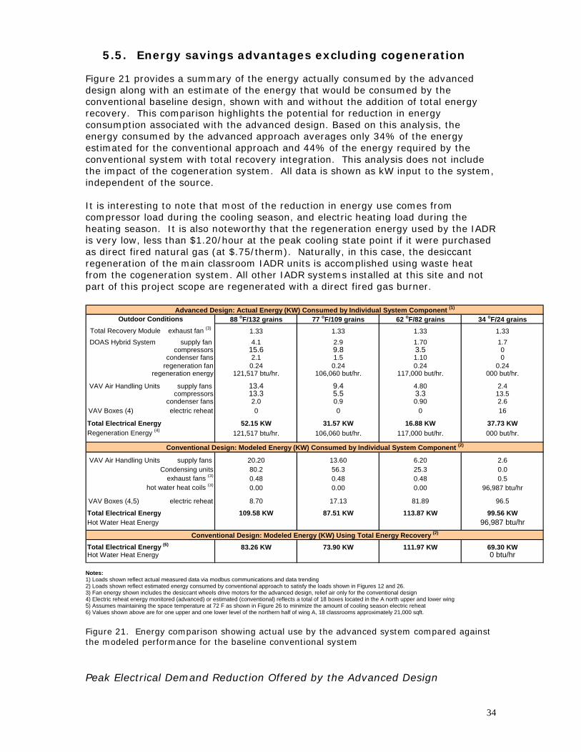
5.5. Energy savings advantages excluding cogeneration Figure 21 provides a summary of the energy actually consumed by the advanced design along with an estimate of the energy that would be consumed by the conventional baseline design, shown with and without the addition of total energy recovery. This comparison highlights the potential for reduction in energy consumption associated with the advanced design. Based on this analysis, the energy consumed by the advanced approach averages only 34% of the energy estimated for the conventional approach and 44% of the energy required by the conventional system with total recovery integration. This analysis does not include the impact of the cogeneration system. All data is shown as kW input to the system, independent of the source. It is interesting to note that most of the reduction in energy use comes from compressor load during the cooling season, and electric heating load during the heating season. It is also noteworthy that the regeneration energy used by the IADR is very low, less than $1.20/hour at the peak cooling state point if it were purchased as direct fired natural gas (at $.75/therm). Naturally, in this case, the desiccant regeneration of the main classroom IADR units is accomplished using waste heat from the cogeneration system. All other IADR systems installed at this site and not part of this project scope are regenerated with a direct fired gas burner.
Outdoor ConditionsTotal Recovery Module exhaust fan (3)
DOAS Hybrid System supply fancompressors
condenser fansregeneration fan
regeneration energy
VAV Air Handling Units supply fanscompressors
condenser fansVAV Boxes (4) electric reheat
Total Electrical EnergyRegeneration Energy (4)
VAV Air Handling Units supply fansCondensing units
exhaust fans (3)
hot water heat coils (3)
VAV Boxes (4,5) electric reheat
Total Electrical EnergyHot Water Heat Energy
Total Electrical Energy (6)
Hot Water Heat Energy 0 btu/hr
Conventional Design: Modeled Energy (KW) Using Total Energy Recovery (2)
83.26 KW 73.90 KW 111.97 KW 69.30 KW
88 oF/132 grains 77 oF/109 grains 62 oF/82 grains 34 oF/24 grains
Conventional Design: Modeled Energy (KW) Consumed by Individual System Component (2)
20.20 13.60 6.20 2.680.2 56.3 25.3 0.00.48 0.48 0.48 0.50.00 0.00 0.00 96,987 btu/hr
8.70 17.13 81.89 96.5
109.58 KW 87.51 KW 113.87 KW 99.56 KW96,987 btu/hr
37.73 KW
0
2.413.52.6
4.803.30.90
00
106,060 but/hr.
13.4
0.24000 but/hr.
1.100.24
117,000 but/hr.
9.4
1.331.703.5
117,000 but/hr.16.88 KW
000 but/hr.
13.32.00
5.50.9
16
52.15 KW 31.57 KW121,517 btu/hr. 106,060 but/hr.
15.62.10.24
121,517 btu/hr.
9.81.50.24
0
4.1
Advanced Design: Actual Energy (KW) Consumed by Individual System Component (1)
1.33 1.332.9
1.331.7
Notes: 1) Loads shown reflect actual measured data via modbus communications and data trending 2) Loads shown reflect estimated energy consumed by conventional approach to satisfy the loads shown in Figures 12 and 26. 3) Fan energy shown includes the desiccant wheels drive motors for the advanced design, relief air only for the conventional design 4) Electric reheat energy monitored (advanced) or estimated (conventional) reflects a total of 18 boxes located in the A north upper and lower wing 5) Assumes maintaining the space temperature at 72 F as shown in Figure 26 to minimize the amount of cooling season electric reheat 6) Values shown above are for one upper and one lower level of the northern half of wing A, 18 classrooms approximately 21,000 sqft.
Figure 21. Energy comparison showing actual use by the advanced system compared against the modeled performance for the baseline conventional system Peak Electrical Demand Reduction Offered by the Advanced Design
34

To estimate the reduction in peak electrical demand offered by the advanced system (and associated electrical infrastructure first cost savings), the actual HVAC peak demand measured at the Pepperell project is compared against that estimated for the conventional system providing comparable performance. The peak cooling season electrical demand of the advanced approach is 49% of that estimated for the conventional approach, before factoring in the further reduction made possible by the engine (see following section). Figure 22 highlights the magnitude of this reduction as well as the large percentage of the overall energy use allocated to peak HVAC conditions with the conventional system. This clearly coveys the fact that any desire to reduce energy use within a school facility must be accomplished by optimizing the HVAC design, especially if comfortable conditions are to be maintained and the building codes are to be followed. Given the magnitude of peak energy reduction summarized by Figure 22, an attempt was made to obtain actual electrical demand data from a school designed and operated as modeled for the conventional design. A high school complex having a similar size and located in Rome Georgia, but operated by a different school district was identified. This school used vapor compression for cooling, a heat pump cycle for heating and electrical reheat as needed during the heating season operation. The school was designed to only deliver approximately 1/3 of the outdoor air volume used for the Pepperell High project and, as importantly, no active humidity control was used (i.e. no cooling season reheat).
Notes: 1) Actual peak demand for the month of August (less engine load). School in full session. 2) Gymnasium and auditorium were in the final stages of construction. Reflected in the conventional load projections.3) High efficiency lighting is installed at this site (1.125 watts/sqft.) 4) Actual HVAC power consumption from trended modbus data (part of the onsite instrumentation).5) Conventional system design as per section 6 (does not include total energy recovery addition)
Lighting Load
35
224 KW
56 KW371 KW Mis cellaneous
HVAC Cooling
Electric Rehea Electric Reheat Lighting Loadt20 KW 194 KW 224 KW
Miscellaneous56 KW
HVAC Cooling898 KW
Actual Peak Cooling Dem andAdvanced Design
Projected Peak Cooling Dem andConventional Design
671 KW Total 1372 KW Total
Figure 22. Electrical comparison of total actual peak demand vs. modeled conventional school
Figure 23 shows the results of this comparison. First, the conventional peak demand projection made in Figure 22 agrees with the actual cooling season conventional data shown in Figure 23, once corrected for the reduced outdoor airflow and lack of active humidity control or cooling season reheat energy. Secondly, the analysis suggests that the advanced system can provide a significant reduction (44% and 47% for the cooling and heating seasons, respectively) in peak HVAC electrical demand while simultaneously providing ASHRAE Standard 62 ventilation along with humidity control below a 55 oF dew point.
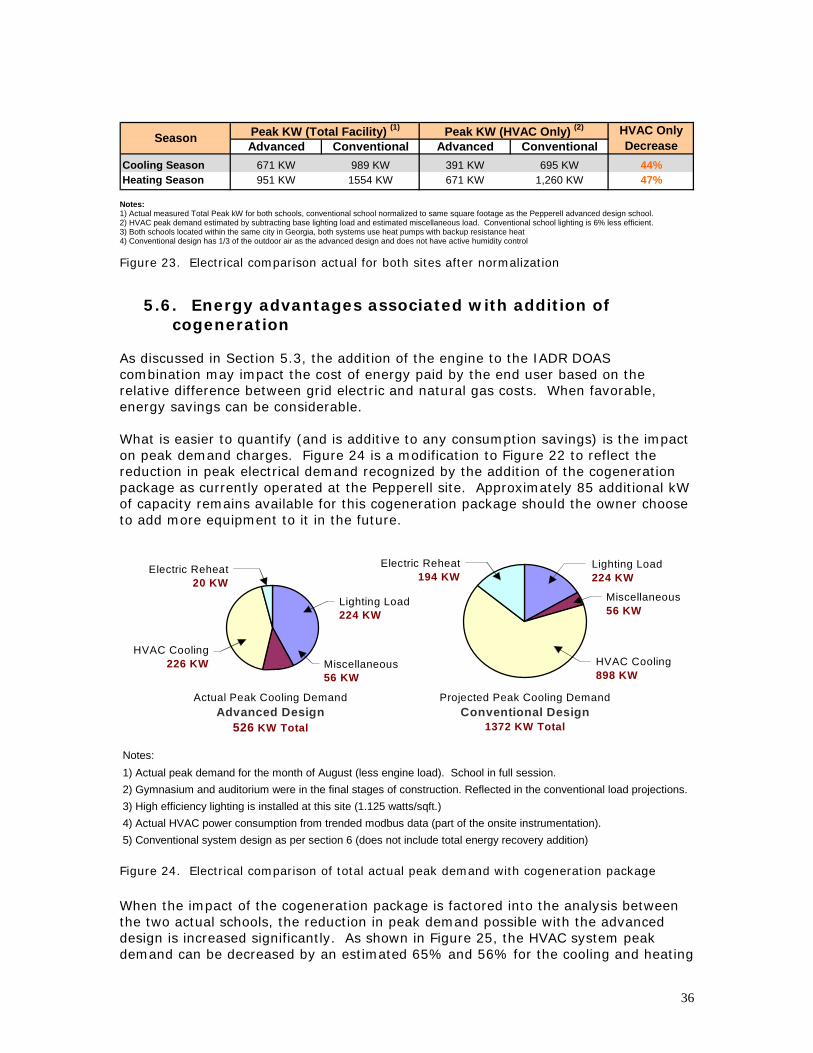
Advanced Conventional Advanced ConventionalCooling Season 671 KW 989 KW 391 KW 695 KW 44%Heating Season 951 KW 1554 KW 671 KW 1,260 KW 47%
Peak KW (Total Facility) (1) HVAC Only Decrease
Peak KW (HVAC Only) (2)Season
Notes: 1) Actual measured Total Peak kW for both schools, conventional school normalized to same square footage as the Pepperell advanced design school. 2) HVAC peak demand estimated by subtracting base lighting load and estimated miscellaneous load. Conventional school lighting is 6% less efficient. 3) Both schools located within the same city in Georgia, both systems use heat pumps with backup resistance heat 4) Conventional design has 1/3 of the outdoor air as the advanced design and does not have active humidity control
Figure 23. Electrical comparison actual for both sites after normalization
5.6. Energy advantages associated with addition of
cogeneration As discussed in Section 5.3, the addition of the engine to the IADR DOAS combination may impact the cost of energy paid by the end user based on the relative difference between grid electric and natural gas costs. When favorable, energy savings can be considerable. What is easier to quantify (and is additive to any consumption savings) is the impact on peak demand charges. Figure 24 is a modification to Figure 22 to reflect the reduction in peak electrical demand recognized by the addition of the cogeneration package as currently operated at the Pepperell site. Approximately 85 additional kW of capacity remains available for this cogeneration package should the owner choose to add more equipment to it in the future.
Notes: 1) Actual peak demand for the month of August (less engine load). School in full session. 2) Gymnasium and auditorium were in the final stages of construction. Reflected in the conventional load projections.3) High efficiency lighting is installed at this site (1.125 watts/sqft.) 4) Actual HVAC power consumption from trended modbus data (part of the onsite instrumentation).5) Conventional system design as per section 6 (does not include total energy recovery addition)
Lighting Load
36
224 KW
56 KW226 KW
20 KW
MiscellaneousHVAC Cooling
Electric Reheat Electric Reheat Lighting Load194 KW 224 KW
Miscellaneous56 KW
HVAC Cooling898 KW
Actual Peak Cooling DemandAdvanced Design
Projected Peak Cooling DemandConventional Design
526 KW Total 1372 KW Total
Figure 24. Electrical comparison of total actual peak demand with cogeneration package
When the impact of the cogeneration package is factored into the analysis between the two actual schools, the reduction in peak demand possible with the advanced design is increased significantly. As shown in Figure 25, the HVAC system peak demand can be decreased by an estimated 65% and 56% for the cooling and heating

system respectively. These reductions would be highly beneficial to projects where a high percentage of the electrical rate package is associated with demand charges.
Advanced Conventional Advanced ConventionalCooling Season 526 KW 989 KW 246 KW 695 KW 65%Heating Season 836 KW 1554 KW 556 KW 1,260 KW 56%Notes: 1) Actual measured Peak KW less engine load, conventional school normalized to same square footage. 2) HVAC peak demand estimated by subtracting base lighting load and estimated miscellaneous load.3) Both schools located within the same city in Georgia, both systems use heat pumps with backup resistance heat4) Conventional design has 1/3 of the outdoor air as the advanced design and does not have active humidity control
Peak KW (Total Facility) (1) HVAC Only Decrease
Peak KW (HVAC Only) (2)Season
Figure 25. Electrical comparison actual for both sites including the cogeneration package
37

6. Comparison with a Conventional VAV Baseline System
To compare costs and benefits of the advanced system, modeling was completed to predict the behavior of a conventional VAV system operated without dedicated outdoor air preconditioning. Energy data is provided for this approach with and without the addition of total energy recovery preconditioning (Figure 21). Figure 26 includes a schematic describing this conventional VAV system and provides the performance state points associated with operating this system to satisfy the same ventilation and humidity control requirements delivered by the advanced approach shown in Figure 17. This schematic shows the addition of a hot water boiler and heating coil to preheat the combined return and outdoor air streams to 55oF during the heating season, since a conventional heat pump approach, especially without total recovery preconditioning, would not produce the heating capacity needed. Glycol is shown since it is common for the outdoor air percentage to be as high as 80% of the total supply airflow during the peak heating mode, which could easily freeze an untreated heating coil. Airflow stations are also shown for the outdoor and return airstreams to ensure that the outdoor air flow remains constant as the supply airflow volume is reduced.
(psychrometrics/airflow) ( o F / grains) ( o C / g/kg) ( o F / grains) ( o C / g/kg) ( o F / grains) ( o C / g/kg) ( o F / grains) ( o C / g/kg)88 oF/132 gr. 31/18.9 77 oF/109 gr. 25/15.6 62 oF/82 gr. 16.7/11.7 34 oF/24 gr. 1.1/3.4
5035 cfm 2376 l/s 5035 cfm 2376 l/s 5035 cfm 2376 l/s 5035 cfm 2376 l/s75.2 oF/68 gr. 24.0/9.7 75 oF/67 gr. 23.9/9.6 72.1 oF/66 gr. 22.3/9.4 70.7 oF/38 gr. 21.5/5.4
6225 cfm 2938 l/s 4810 cfm 2270 l/s 2905 cfm 1371 l/s 1311 cfm 619 l/s79.3 oF/89 gr. 26.3/12.7 75.8 oF/83 gr. 24.3/11.9 67 oF/74 gr. 19.4/10.6 45.4 oF/28 gr. 7.4/4.0
9,150 cfm 4318 l/s 7,735 cfm 3650 l/s 5,830 cfm 2751 l/s 4,236 cfm 1999 l/s55 oF/59 gr. 12.8/8.4 55 oF/59 gr. 12.8/8.4 55 oF/58 gr. 12.8/8.3 45.4 oF/28 gr. 7.4/4.09,150 cfm 4318 l/s 7,735 cfm 3650 l/s 5,830 cfm 2751 l/s 4,236 cfm 1999 l/s
56 oF/59 gr. 13.3/8.4 56 oF/59 gr. 13.3/8.4 56 oF/58 gr. 13.3/8.3 56 oF/28 gr. 13.3/4.09,150 cfm 4318 l/s 7,735 cfm 3650 l/s 5,830 cfm 2751 l/s 4,236 cfm 1999 l/s
62 oF/59 gr. 16.7/8.4 66 oF/59 gr. 18.9/8.4 78.2 oF/58 gr. 25.7/8.3 92 oF/34 gr. 33.3/4.91,830 cfm 864 l/s 1,520 cfm 717 l/s 1105 cfm 521 l/s 912 cfm 430 l/s
75.2 oF/68 gr. 24.0/9.7 75 oF/67 gr. 23.9/9.6 72.1 oF/66 gr. 22.3/9.4 70.7 oF/38 gr. 21.5/5.4
Weather Conditions Evaluated88 oF/132 grains 77 oF/109 grains 62 oF/82 grains 34 oF/24 grains
(4) Air to AHU Heating Coil
System State Point
(1) Outdoor Air
(2) Return Air to AHU
(3) Mixed Air to AHU Coils
(5) VAV AHU Supply Air
(6) VAV Box Supply Air (1)
(7) Relief Air
1
2
3 45
Lower Level VAV AHU with rem ote Condenser
Typical Clas s room Wing with VAV Boxes and Electric Reheat
to remote condenser
to remote condenser
Rem ote Condens er for VAV AHUs
6
Upper Level VAV AHU
Glycol Boiler for VAV AHU Heating
t o boiler
to bo iler
7
A irf low Station
Notes: 1) Data presented reflects the airflow and psychometric state points required to maintain space conditions comparable to the advanced system (Figure 3) 2) These conditions reflects data collected during morning warm-up following night-setback, thermal storage of building mass evident in sensible load 3) To minimize reheat requirements, this analysis allows the space temperature to be maintained at 72oF rather than the goal of 75oF (same dew point used). 4) Values shown above are for one upper and one lower level of the northern half of wing A, 18 classrooms approximately 20,000 sqft.
Figure 26. Baseline design with conventional VAV AHU and without total energy recovery
38

39
As expected, a careful review of the state points shown for the conventional approach confirm that during the cooling mode, a substantial reheat load exists at the VAV boxes. Since the minimum box airflow setting must be high enough to deliver the required outdoor air volume and since the leaving coil temperature must be low enough to satisfy the space internal latent load (as shown in Figure 12), many spaces would likely be quickly over-cooled without this reheat capability.

40
7. Additional Advantages of the Advanced IADR System
Trended data collected over the first full cooling season, and reflected by Figure 20 proved the advanced system capable of maintaining the desired space dew point of 55oF over a wide range of outdoor air conditions (see Figure 17). As reported in a May 2003 ASHRAE Journal article, the lower space humidity produced comfort conditions at elevated space temperature set points (i.e. 75oF) (4,5,15). Indoor Air Quality (TVOC and CO2 testing) To benchmark the indoor air quality maintained within the Pepperell High School, air quality samples were collected from all three main classroom areas using adsorbent filled retention tubes, and were analyzed by the Georgia Tech Research Institute. The results of this total volatile organic compound (TVOC) testing showed the air quality in the school to be excellent, averaging less than 200 micrograms/m3, better than the best of those reported on in the 2003 ASHRAE Journal article (4). Similar results were found for CO2 data collected at the site coincident with the TVOC testing. Green Building (LEED) and Outdoor Environmental Advantages Although the construction budgeting priorities did not allow for formal LEED certification of the Pepperell High facility, an informal analysis completed by a LEED accredited professional confirmed that the facility would have been eligible for approximately 43 points, 23 of which provided by the HVAC system efficiency and ASHRAE compliance (only 26 total points are required for certification), qualifying the facility for a LEED Gold level rating. An analysis of electrical use at the site was extended to look at carbon emissions since the local utility is powered by coal. The advanced design is projected to produce approximately 850 fewer tons of carbon emissions annually than would the conventional design. Had the advanced design utilized chilled water as opposed to the high efficiency vapor compression approach, an estimated 5,000,000 gallons of water would have been required by the cooling towers annually. Eliminating this water use is one more significant advantage offered by the advanced system approach. Background Classroom Noise (ANSI/ASA Standard S12.60-2002) Another important factor in maintaining a desirable teaching environment is controlling background noise in classroom areas. Much industry controversy has surrounded a new ANSI standard requiring background noise levels to be maintained below 35 decibels. Many commonly used HVAC designs will not allow the background noise to approach this level. Testing was conducted in 10 representative Pepperell classrooms using a Bruel and Kjaer sound meter reporting sound power levels as dbA. The average background noise level within the unoccupied rooms measured was 34.5 dbA. The maximum level measured was 39.5 dbA and the minimum was 29.7 dbA.

41
8. Conclusions and Recommended Future Work
This research/demonstration project successfully demonstrated the performance advantages offered by an advanced “integrated energy system” which combined a prepackaged cogeneration “prime mover” with prepackaged integrated active desiccant rooftop (IADR) systems, matched with total energy recovery systems, to serve as effective dedicated outdoor air systems. This integrated energy system serves a conventional high school facility, where the level of design sophistication is typically limited and where budgetary concerns are high, showing that this advanced design approach incorporating “on-site power generation” is feasible for any project type in which electrical costs are high relative to natural gas. A custom build cogeneration package and four integrated active desiccant–vapor compression hybrid rooftop systems (IADR), modified to include hot water coils to effectively use the heat rejected from the cogeneration package, were provided as “plug and play” components to the installing contractor. The only additional field connections required included the hot water loop, natural gas, and twisted pair to the adjacent modbus control panel included in the IADR. The advanced design approach detailed in this report provides an effective “road-map” for constructing and operating comfortable, healthy, energy efficient and cost effective schools that follow current ASHRAE recommendations and meet all code requirements. Decoupling the latent load from the main VAV system, applying a dedicated outdoor air system with low dew point capabilities, using high efficiency vapor compression – heat pump systems, advanced control algorithms and incorporating on-site cogeneration showed measurable improvements when compared to a conventional baseline system. An effective match was observed between the output of electrical load and heat from the engine and the input of services required by the four IADR systems. The required cooling capacity was reduced by 44% (475 tons vs. 850 tons) and the cooling season peak demand was cut by an estimated 62% (526 kW vs. 1372). The 543,000 Btu/hour provided by the engine during peak heating needs offset approximately 170 kW of electric resistance heat (located in individual VAV boxes). The rapid escalation in the cost of natural gas during the installation phase of this project and other challenges significantly reduced the viable operating hours of cogeneration at this site. More data will be collected at the site over time. Now that a cogeneration system design, IADR modifications and system controls have been completed and “de-bugged” for this advanced, integrated energy system, it is recommended that additional sites be completed in areas where the cost of electrical energy and associated demand charges are high relative to the cost of natural gas.

42
9. Acknowledgement
SEMCO would like to take this opportunity to thank the Department of Energy and Oak Ridge National Laboratory for their support of this project. We would also like to especially thank the support given by the Floyd County School district. They proved an exceptional partner and without this support this project would not have been possible. This is especially true for Jack Gresham, the Director of Facilities for Floyd County Schools. We would also like to thank the fine efforts and dedication of our engineering consulting partners, Kirk Mescher with C&M Engineering, Ben Elkin and Associates and the engineer of record, Southern A&E.

10. References (1) ASHRAE 2001, “Ventilation for Acceptable Indoor Air Quality”, ASHRAE Standard 62, Atlanta. (2) ASHRAE 1999, “Energy Standard for Buildings”, ASHRAE Standard 90.1, Atlanta. (3) ASHRAE 1992, “Thermal Environmental Conditions for Human Occupancy”, ASHRAE Standard 55, Atlanta. (4) Fischer J., Bayer C.W., 2003, “Report Card on Humidity Control”, ASHRAE Journal May, 2003 (5) Fischer J., Sand J.R., 2005, “Field Test and Performance Verification: Integrated Active Desiccant Rooftop (IADR) Hybrid System Installed in a School Facility” (ORNL/SUB-01-4000025209), Oak Ridge National Laboratory, Oak Ridge, Tennessee. (6) Bayer CW, Hendry RJ, Crow SA, Fischer JC (2002) The Relationship Between Humidity and Indoor Air Quality in Schools., Proceedings of Indoor Air 2002, International Academy of Indoor Air Sciences, Monterey, CA, II:818-823. (7) Fischer J., 1996. “Optimizing IAQ, Humidity Control and Energy Efficiency in School Environments…”, Proceedings of ASHRAE IAQ ’96. ASHRAE pp:188-203. (8) Bayer CW, Crow SA, Fischer J.C., 2000, Causes of Indoor Air Quality Problems in Schools: Summary of Scientific Research, ORNL/Sub/94-SV044/1, Washington, DC, US Department of Energy (9) Bayer, CW; Downing, CC., 1992 "Indoor Conditions in Schools with Insufficient Humidity Control", Proceedings of IAQ '92, ASHRAE, San Francisco, 1992. (10) Downing C. and Bayer C.W., 1993. “Classroom indoor air quality versus ventilation rate”, ASHRAE Trans 99:1099-1103 (11) R&D Magazine 2005, "Top 100 Innovative Products" Award for 2005 from R&D Magazine - Revolution™ System, R&D Magazine July 2005. (12) Sand J.R., Fischer J., 2006, “Air Conditioning and Heat Pump Efficiencies – How Efficient Can We Make It”, Oak Ridge National Laboratory, Oak Ridge, Tennessee (13) Petrov A.Y., Sand J.R., Zaltash A., Fischer J., Mitchell R., and Wetherington G.R., Performance Analysis of Integrated Active Desiccant Rooftop Air-Conditioning System Operating in Heating Mode, Proceedings of IMECDE-2005, Paper IMECE 2005-79238, November 5-11, 2005, Orlando, FL (14) Petrov A.Y., Sand J.R., Fischer J., 2006, “SEMCO Integrated Active Desiccant Rooftop’s Low Dew Point Capabilities”, Oak Ridge National Laboratory, Oak Ridge, Tennessee (15) Berglund, L. 1998. “Comfort and Humidity”, ASHRAE Journal, August 1998 pp. 35-41 (16) Mumma, S. 2001. “Designing Dedicated Outdoor Air Systems”, ASHRAE Journal May, 2001 pp:28-31. (17) ASHRAE 2001, “2001 Fundamentals”, ASHRAE, Atlanta. (18) Henderson, H. and Rengarajan K., 1996. “A model to predict the latent capacity of air conditioners and heat pumps at part-load conditions…”, ASHRAE Trans 102:266-72 (19) Khattar, M., Ramanan, N. and Swami, M. 1985. “Fan cycling effects on air conditioner moisture removal..”, Intl. Symposium on Moisture and Humidity, Washington, DC
43

44
(20) Fischer J., Sand J.R., 2004, “Desiccant Based Combined Systems: Integrated Active Desiccant Rooftop Hybrid System Development and Testing” (ORNL/SUB-01-4000010402), Oak Ridge National Laboratory, Oak Ridge, Tennessee (21) Fischer J., Mescher K., Elkin B., McCune S., Gresham J., 2007, “High Performance Schools – High Marks for Energy Efficiency, Humidity Control, Indoor Air Quality and First Cost”, ASHRAE Journal May, 2007, Atlanta.

45
Appendices
1) Listing of Instrumentation for IADR Systems 2) Floyd County Schools letter of interest 3) Drawing of the Williams cogeneration package and approximate dimensions 4) Flow schematic of advanced energy system

46
Listing of Instrumentation for IADR Systems Partial listing of Performance State Points Monitored Outdoor temp and RH Outdoor airflow Return temp and RH Return airflow Supply temp and RH Supply airflow Entering DX temp and RH Leaving DX temp and humidity Regeneration temp in Regeneration temp out Leaving desiccant wheel temp and humidity System on/off Supply fan on/off Compressor on/off Compressor VFD Condenser fan on/off Condenser fan VFD Regenerator fan on /off Burner power on/off Reversing valve (heat pump) Desiccant wheel supply side delta pressure Desiccant wheel regeneration side delta pressure Condenser coil air pressure loss Leaving condenser air temp Starter panel temp Suction pressure and temperature Condensing pressure and temperature Electric power to supply fan Electric power to regeneration fan Electric power to compressor Electric power to condenser fan Electric power to desiccant wheel Outdoor damper position Return damper position Bypass damper position Natural gas valve position Supply fan VFD Regeneration fan VFD Desiccant wheel VFD


1 OF 2.100" = 1.000"
5-20-05
ANGLES +/-
+/-
+/-
+/-
FINISH
FRACTIONS +/-
1 PLACE DECIMALS
2 PLACE DECIMALS
3 PLACE DECIMALS
J.C.E.
TOLERANCES
APV
DWN
STUB INFORMATION
DWG #1SHEET REVISION
DRAWING NO.
SCALE
MATERIAL
30'
W. W. WILLIAMS
APVDATEDESCRIPTIONREV
LOUVER OPENING22" X 66"
131.500
72.000
GENERATOR
53.000
23.000W
ATE
R R
ETU
RN
WAT
ER
SU
PPL
Y
NA
TUR
AL G
AS
9.500
12.000
152.000
22" X 66"LOUVER OPENING

Advanced Design with Active Desiccant Hybrid Dedicated Outdoor Air System Preconditioning with Cogeneration
1 23 4
5
6
7
8
9
1011
Total Energy Recovery Module
Active Desiccant - Vapor Compression Hybrid DOAS
(IADR - DOAS) Lower Level VAV AHU with remote Heat Pump Condenser
Typical Classroom Wing with VAV Boxes and Electric Reheat
13
to integrated condenser/heat pump
to remote condenser/heat pump
to remote condenser/heat pump
Williams Cogeneration Packagewith Deutz Natural Gas Engine
12
14
Upper Level VAV AHU