ITEM PAGE - ENVIRO-TEC · PIPING PACKAGES • CODE DESCRIPTIONS 6 Johnson Controls VH FAN COILS...
18
Transcript of ITEM PAGE - ENVIRO-TEC · PIPING PACKAGES • CODE DESCRIPTIONS 6 Johnson Controls VH FAN COILS...


ITEM PAGEGeneral Notes and Legend . . . . . . . . . . . . . . . . . . . . . . . . . . . . . . . . . . . . . . . . . . . . . . . . . . . . . . . . 3Piping Package Code Descriptions & Diagrams
VAV Products and HL, HP, VF, and CDH/CDV Fan Coils . . . . . . . . . . . . . . . . . . . . . . . . . . . . . . . . 4VH Fan Coil, 2-Way . . . . . . . . . . . . . . . . . . . . . . . . . . . . . . . . . . . . . . . . . . . . . . . . . . . . . . . . . . . 5VH Fan Coil, 3-Way . . . . . . . . . . . . . . . . . . . . . . . . . . . . . . . . . . . . . . . . . . . . . . . . . . . . . . . . . . . 6VH Fan Coil, 3-Way with Balance Bypass Valve . . . . . . . . . . . . . . . . . . . . . . . . . . . . . . . . . . . . . . 7
Guide Specifications . . . . . . . . . . . . . . . . . . . . . . . . . . . . . . . . . . . . . . . . . . . . . . . . . . . . . . . . . . . . . 7
Component SpecificationsManual Ball Valve with Memory Stop (BVMS) . . . . . . . . . . . . . . . . . . . . . . . . . . . . . . . . . . . . . . 8Flexible Hose Kits, 18" (FH) . . . . . . . . . . . . . . . . . . . . . . . . . . . . . . . . . . . . . . . . . . . . . . . . . . . . . 8Typical 2-Way Control Valve . . . . . . . . . . . . . . . . . . . . . . . . . . . . . . . . . . . . . . . . . . . . . . . . . . . . 8Typical 3-Way Control Valve . . . . . . . . . . . . . . . . . . . . . . . . . . . . . . . . . . . . . . . . . . . . . . . . . . . . 9Typical 2-Way Modulating Control Valve . . . . . . . . . . . . . . . . . . . . . . . . . . . . . . . . . . . . . . . . . . 9Typical 3-Way Modulating Control Valve . . . . . . . . . . . . . . . . . . . . . . . . . . . . . . . . . . . . . . . . . . 9Automatic Fixed Flow Control (FC) . . . . . . . . . . . . . . . . . . . . . . . . . . . . . . . . . . . . . . . . . . . . . . 10Automatic Cartridge Flow Control (FCN, FCS) . . . . . . . . . . . . . . . . . . . . . . . . . . . . . . . . . . . . . . 10Adjustable Flow Circuit Setter (AFS) . . . . . . . . . . . . . . . . . . . . . . . . . . . . . . . . . . . . . . . . . . . . . 10Balance Bypass Valve (BPV) . . . . . . . . . . . . . . . . . . . . . . . . . . . . . . . . . . . . . . . . . . . . . . . . . . . . 11Unions . . . . . . . . . . . . . . . . . . . . . . . . . . . . . . . . . . . . . . . . . . . . . . . . . . . . . . . . . . . . . . . . . . . . 11Y-Strainer (Y-STR) . . . . . . . . . . . . . . . . . . . . . . . . . . . . . . . . . . . . . . . . . . . . . . . . . . . . . . . . . . . . 11Cleanout Valve for Y-Strainer (Y-CO) . . . . . . . . . . . . . . . . . . . . . . . . . . . . . . . . . . . . . . . . . . . . . 12Optional Pressure/Temperature Test Port Locations (P/T) . . . . . . . . . . . . . . . . . . . . . . . . . . . . . . 12Aqua-Thermostat . . . . . . . . . . . . . . . . . . . . . . . . . . . . . . . . . . . . . . . . . . . . . . . . . . . . . . . . . . . . 12
Copper Tube DataCopper Tube Dimensional & Physical Data. . . . . . . . . . . . . . . . . . . . . . . . . . . . . . . . . . . . . . . . . 13Soldered and Brazed Joint Rated Working Pressure. . . . . . . . . . . . . . . . . . . . . . . . . . . . . . . . . . 13Copper Tube Rated Internal Working Pressure. . . . . . . . . . . . . . . . . . . . . . . . . . . . . . . . . . . . . . 14Soldered and Brazed Joints Pressure & Temperature Ratings. . . . . . . . . . . . . . . . . . . . . . . . . . . 15
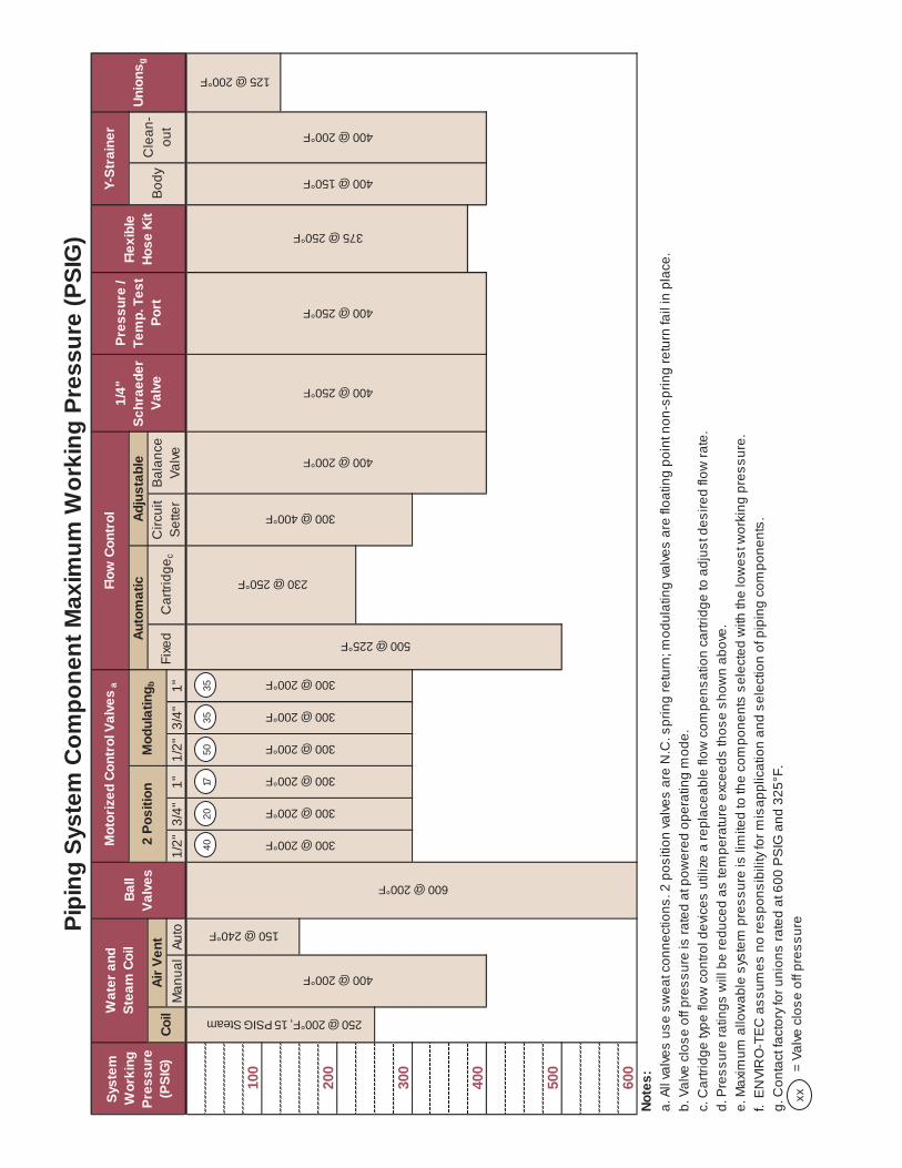
Piping System Component Maximum Working Pressure . . . . . . . . . . . . . . . . . . . . . . . . . . . . . . . . . 16
PIPING PACKAGES • TABLE OF CONTENTS
2 Johnson Controls
All data herein is subject to change without notice. Some drawings are not shown in this catalog. Refer to www.enviro-tec.com for current drawings.
GENERAL NOTES • PIPING PACKAGES
Johnson Controls 3
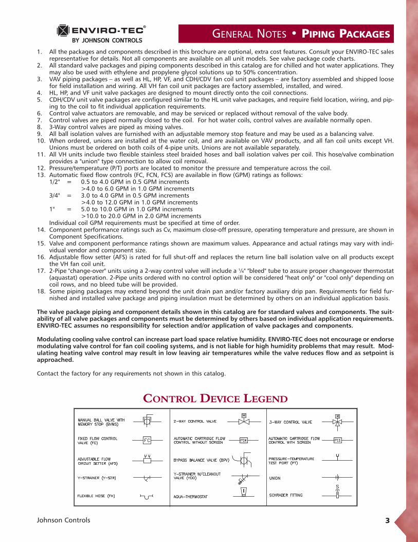
CONTROL DEVICE LEGEND
1. All the packages and components described in this brochure are optional, extra cost features. Consult your ENVIRO-TEC salesrepresentative for details. Not all components are available on all unit models. See valve package code charts.
2. All standard valve packages and piping components described in this catalog are for chilled and hot water applications. Theymay also be used with ethylene and propylene glycol solutions up to 50% concentration.
3. VAV piping packages – as well as HL, HP, VF, and CDH/CDV fan coil unit packages – are factory assembled and shipped loosefor field installation and wiring. All VH fan coil unit packages are factory assembled, installed, and wired.
4. HL, HP, and VF unit valve packages are designed to mount directly onto the coil connections.5. CDH/CDV unit valve packages are configured similar to the HL unit valve packages, and require field location, wiring, and pip-
ing to the coil to fit individual application requirements.6. Control valve actuators are removable, and may be serviced or replaced without removal of the valve body.7. Control valves are piped normally closed to the coil. For hot water coils, control valves are available normally open.8. 3-Way control valves are piped as mixing valves.9. All ball isolation valves are furnished with an adjustable memory stop feature and may be used as a balancing valve.10. When ordered, unions are installed at the water coil, and are available on VAV products, and all fan coil units except VH.
Unions must be ordered on both coils of 4-pipe units. Unions are not available separately.11. All VH units include two flexible stainless steel braided hoses and ball isolation valves per coil. This hose/valve combination
provides a "union" type connection to allow coil removal.12. Pressure/temperature (P/T) ports are located to monitor the pressure and temperature across the coil.13. Automatic fixed flow controls (FC, FCN, FCS) are available in flow (GPM) ratings as follows:
1/2" = 0.5 to 4.0 GPM in 0.5 GPM increments>4.0 to 6.0 GPM in 1.0 GPM increments
3/4" = 3.0 to 4.0 GPM in 0.5 GPM increments>4.0 to 12.0 GPM in 1.0 GPM increments
1" = 5.0 to 10.0 GPM in 1.0 GPM increments>10.0 to 20.0 GPM in 2.0 GPM increments
Individual coil GPM requirements must be specified at time of order.14. Component performance ratings such as Cv, maximum close-off pressure, operating temperature and pressure, are shown in
Component Specifications.15. Valve and component performance ratings shown are maximum values. Appearance and actual ratings may vary with indi-
vidual vendor and component size.16. Adjustable flow setter (AFS) is rated for full shut-off and replaces the return line ball isolation valve on all products except
the VH fan coil unit.17. 2-Pipe "change-over" units using a 2-way control valve will include a ¼" "bleed" tube to assure proper changeover thermostat
(aquastat) operation. 2-Pipe units ordered with no control option will be considered "heat only" or "cool only" depending oncoil rows, and no bleed tube will be provided.
18. Some piping packages may extend beyond the unit drain pan and/or factory auxiliary drip pan. Requirements for field fur-nished and installed valve package and piping insulation must be determined by others on an individual application basis.
The valve package piping and component details shown in this catalog are for standard valves and components. The suit-ability of all valve packages and components must be determined by others based on individual application requirements.ENVIRO-TEC assumes no responsibility for selection and/or application of valve packages and components.
Modulating cooling valve control can increase part load space relative humidity. ENVIRO-TEC does not encourage or endorsemodulating valve control for fan coil cooling systems, and is not liable for high humidity problems that may result. Mod-ulating heating valve control may result in low leaving air temperatures while the valve reduces flow and as setpoint isapproached.
Contact the factory for any requirements not shown in this catalog.

PIPING PACKAGES • CODE DESCRIPTIONS
4 Johnson Controls
BVMS FC AFS 1/2" 3/4" 1"* 1/2" 3/4" 1"*24 x x25 x x x29 x x x
x
P/T Ports
2-WAY PIPING PACKAGE
xxx
ComponentsPackage Code
UnionsValve Size
x x
LEGEND, COMPONENT PRESSURE RATINGSBVMS: Manual Ball Valves w/Memory Stop, 600 PSIGFC: Fixed Flow Control, 500 PSIGAFS Adjustable Flow Circuit Setter, 300 PSIGP/T Port: Pressure/Temperature Test Port, 400 PSIGUnion: 125 PSIG (contact factory for 600 PSIG)Control Valve: 300 PSIGBPV: Balance Bypass Valve, 400 PSIG
NOTES:1. All drawings subject to change without prior notice.2. Diagrams show component position in relation to fluid
flow. Actual valve package configuration varies with unittype, hand connection, and pipe size.
3. 1/4" bleed line is furnished on 2-pipe cool and heat autochangeover systems.
* 1" piping packages available on HP and CDH/CDV only.
Code 242-Way Control Valve and Ball
Valves With Memory Stop
Code 252-Way Control Valve, Ball Valves withMemory Stop, and Fixed Flow Control
Code 292-Way Control Valve, Ball Valve with
Memory Stop, and Adjustable Flow Setter
Code 363-Way Control Valve and Ball
Valves With Memory Stop
Code 373-Way Control Valve, Ball Valves withMemory Stop, and Fixed Flow Control
Code 413-Way Control Valve, Ball Valve With
Memory Stop, and Adjustable Flow Setter
Code 503-Way Control Valve, Ball Valve in Bypass,
and Ball Valves With Memory Stop
Code 533-Way Control Valve, Ball Valve in Bypass, Ball Valve
With Memory Stop, and Adjustable Flow Setter
BVMS FC AFS 1/2" 3/4" 1"* 1/2" 3/4" 1"*36 x x37 x x x41 x x x
Package Code
Valve SizeComponents
x
P/T Ports
3-WAY PIPING PACKAGEUnions
x xx x x
BVMS FC AFS 1/2" 3/4" 1"* 1/2" 3/4" 1"*50 x x53 x x x
ComponentsPackage Code
3-WAY PACKAGE WITH BALANCE BYPASS VALVE
x x x
Unions P/T Ports
x x x
Valve Size
VAV PRODUCTS AND HL, HP, VF, CDH/CDV FAN COILS(VAV products available with 2-way packages only)

CODE DESCRIPTIONS • PIPING PACKAGES
Johnson Controls 5
VH FAN COILS
NOTES:1. All drawings subject to change without
prior notice.2. Diagrams show component position in
relation to fluid flow. Actual valve pack-age configuration varies with unit type,hand connection, and pipe size.
3. 1/4" bleed line is furnished on 2-pipe cooland heat auto changeover systems.
Valve SizeFC AFS Y-STR FCN FCS 1/2"
32 x x33 x x x34 x x x60 x x x x61 x x x x x62 x x x x x63 x x64 x x
2-WAY PIPING PACKAGESY-CO P/T Ports
Package Code
Components
Code 322-Way Control Valve Only
Code 332-Way Control Valve and Adjustable Flow Setter
Code 342-Way Control Valve and
Fixed Flow Control
Code 602-Way Control Valve and Y Strainer
Code 612-Way Control Valve, Fixed Flow Control,
and Y Strainer
Code 622-Way Control Valve, Adjustable Flow
Control, and Y Strainer
Code 632-Way Control Valve and
Auto Cartridge Flow Control
Code 642-Way Control Valve and Auto
Cartridge Flow Control with Screen
LEGEND, COMPONENT PRESSURE RATINGSFC: Fixed Flow Control, 500 PSIGAFS: Adjustable Flow Circuit Setter, 300 PSIGY-STR: Y Strainer, 400 PSIGFCN: Fixed Cartridge Flow Control w/ PT Ports and No Screen, 230 PSIGFCS: Fixed Cartridge Flow Control with PT Ports and Screen, 230 PSIGY-CO: Y-Strainer Cleanout, 400 PSIGP/T Port: Pressure/Temperature Test Port, 400 PSIGControl Valve: 300 PSIG

PIPING PACKAGES • CODE DESCRIPTIONS
6 Johnson Controls
VH FAN COILS
Valve SizeFC AFS Y-STR FCN FCS 1/2"
43 x x44 x x x45 x x x46 x x x x47 x x x x x48 x x x x x65 x x66 x x
Package Code
3-WAY PIPING PACKAGESY-CO P/T PortsComponents
Code 433-Way Control Valve Only
Code 443-Way Control Valve and
Fixed Flow Control
Code 453-Way Control Valve and Adjustable Flow Setter
Code 463-Way Control Valve and Y Strainer
Code 473-Way Control Valve, Fixed Flow
Control and Y Strainer
Code 483-Way Control Valve,
Adjustable Flow Setter and Y Strainer
Code 653-Way Control Valve and
Auto Cartridge Flow Control
Code 663-Way Control Valve and Auto
Cartridge Flow Control With Screen
NOTES:1. All drawings subject to change with-
out prior notice.2. Diagrams show component position in
relation to fluid flow. Actual valve pack-age configuration varies with unittype, hand connection, and pipe size.
3. 1/4" bleed line is furnished on 2-pipecool and heat auto changeover systems.
LEGEND, COMPONENT PRESSURE RATINGSFC: Fixed Flow Control, 500 PSIGAFS: Adjustable Flow Circuit Setter, 300 PSIGY-STR: Y Strainer, 400 PSIGFCN: Fixed Cartridge Flow Control w/ PT Ports and No Screen, 230 PSIGFCS: Fixed Cartridge Flow Control with PT Ports and Screen, 230 PSIGY-CO: Y-Strainer Cleanout, 400 PSIGP/T Port: Pressure/Temperature Test Port, 400 PSIGControl Valve: 300 PSIG
CODE DESCRIPTIONS • PIPING PACKAGES
Johnson Controls 7
VH FAN COILS
PIPING PACKAGE GUIDE SPECIFICATIONS
Valve SizeFC AFS Y-STR FCN FCS 1/2"
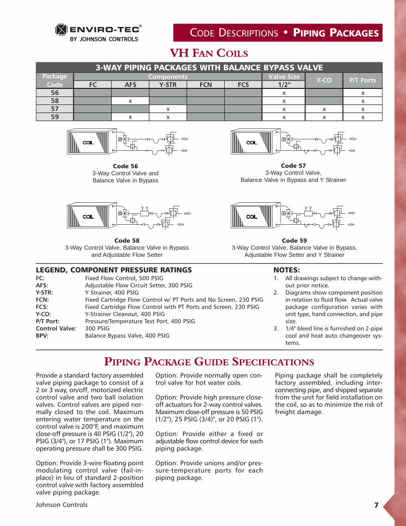
56 x x58 x x x57 x x x x59 x x x x x
Y-CO P/T PortsPackage
Code Components
3-WAY PIPING PACKAGES WITH BALANCE BYPASS VALVE
Code 563-Way Control Valve and Balance Valve in Bypass
Code 573-Way Control Valve,
Balance Valve in Bypass and Y Strainer
Code 583-Way Control Valve, Balance Valve in Bypass
and Adjustable Flow Setter
Code 593-Way Control Valve, Balance Valve in Bypass,
Adjustable Flow Setter and Y Strainer
NOTES:1. All drawings subject to change with-
out prior notice.2. Diagrams show component position
in relation to fluid flow. Actual valvepackage configuration varies withunit type, hand connection, and pipesize.
3. 1/4" bleed line is furnished on 2-pipecool and heat auto changeover sys-tems.
LEGEND, COMPONENT PRESSURE RATINGSFC: Fixed Flow Control, 500 PSIGAFS: Adjustable Flow Circuit Setter, 300 PSIGY-STR: Y Strainer, 400 PSIGFCN: Fixed Cartridge Flow Control w/ PT Ports and No Screen, 230 PSIGFCS: Fixed Cartridge Flow Control with PT Ports and Screen, 230 PSIGY-CO: Y-Strainer Cleanout, 400 PSIGP/T Port: Pressure/Temperature Test Port, 400 PSIGControl Valve: 300 PSIGBPV: Balance Bypass Valve, 400 PSIG
Provide a standard factory assembledvalve piping package to consist of a2 or 3 way, on/off, motorized electriccontrol valve and two ball isolationvalves. Control valves are piped nor-mally closed to the coil. Maximumentering water temperature on thecontrol valve is 200°F, and maximumclose-off pressure is 40 PSIG (1/2"), 20PSIG (3/4"), or 17 PSIG (1"). Maximumoperating pressure shall be 300 PSIG.
Option: Provide 3-wire floating pointmodulating control valve (fail-in-place) in lieu of standard 2-positioncontrol valve with factory assembledvalve piping package.
Option: Provide normally open con-trol valve for hot water coils.
Option: Provide high pressure close-off actuators for 2-way control valves.Maximum close-off pressure is 50 PSIG(1/2"), 25 PSIG (3/4)", or 20 PSIG (1").
Option: Provide either a fixed oradjustable flow control device for eachpiping package.
Option: Provide unions and/or pres-sure-temperature ports for eachpiping package.
Piping package shall be completely factory assembled, including inter-connecting pipe, and shipped separatefrom the unit for field installation onthe coil, so as to minimize the risk offreight damage.

PIPING PACKAGES • SPECIFICATIONS
8 Johnson Controls
Manual Ball Valve w/Memory Stop (BVMS)An adjustable stop position lever to limit travel of the On/Offhandle. This allows the ball valve to be closed, and returnedto the balance setting position without re-testing the system. 1/2" size shown.Nominal Size: 1/2" 3/4" 1"Body Material: Brass Brass BrassBall: Hard Chrome Hard Chrome Hard Chrome
Plated Plated PlatedSeats: Teflon Teflon TeflonStem Seal: (2) Viton O-Rings Teflon TeflonConnection: Sweat Sweat SweatPressure Rating 600 600 600(psig):Temp. Rating, °F: 325 325 325Cv: 17 32 27
Typical 2-Way, 2-Position Control ValveA 2-position water control valve driven open with springreturn upon a call for heating or cooling to maintain spacetemperature. In open position, water can flow throughthe unit's water coil to heat or cool the space dependingon supply water temperature. In closed position, watercannot flow through the water coil. Control valves arepiped normally closed to the coil as standard. Valve actu-ators can be line or low (24VAC) voltage.Nominal Size 1/2" 2-Way 3/4" 2-Way 1" 2-WayBody Material: Brass Brass BrassConnection: Sweat Sweat SweatPressure Rating (psig): 300 300 300Temperature Rating, °F: 200 200 200Cv: 2.5 5.0 8.0Maximum Close-off
Pressure, Std. (PSIG): 40 20 17High Close-off: 50 25 20Power Consumption: 7VA 7VA 7VA
Flexible Hose Kits, 18" (FH)Materials: EPDM inner lined, Kevlar®
reinforced hose with stainless steel outer covering
Flow Rates: 0.5 to 12.0 GPM, based on application
Pressure Temp. Rating 375 PSIG @ 250°F (450 PSIG test pressure)Minimum Burst Pressure: 1500 PSIFlame Spread: Not greater than 25 per UL 723Smoke Development: Not greater than 50 per UL 723Ball Valve w/Memory Stop: Full port brass
Ball: Stainless steelSeats: TeflonStem Seal: (2) Viton O-RingsPressure Rating: 600 PSIG WOGTemperature Rating: 325°FCv: 20
Available in 1/2" size only.
NOTE: Photos are for representation purposes only. Vendors and models subject to change without notice.

SPECIFICATIONS • PIPING PACKAGES
Johnson Controls 9
Typical 3-Way, 2-Position Control ValveA 2-position water control valve driven open with spring return(bypass) upon a call for heating or cooling to maintain spacetemperature. Energized, the bypass port is blocked, and watercan flow through the unit's water coil to heat or cool the spacedepending on the supply water temperature. De-energized, watercannot flow through the water coil but is forced to flow throughthe bypass port, bypassing the coil. Control valves are pipednormally closed to the coil as standard (in full bypass). Valveactuators can be line or low (24VAC) voltage.
Nominal Size 1/2" 3-Way 3/4" 3-Way 1" 3-WayBody Material: Brass Brass BrassConnection: Sweat Sweat SweatPressure Rating (psig): 300 300 300Temperature Rating, °F: 200 200 200Cv: 3.0 5.0 8.0Maximum Close-off
Pressure (PSIG): N/A N/A N/APower Consumption: 7VA 7VA 7VA
Typical 2-Way Modulating Control ValveA 3-wire floating point, fail-in-place (non-spring return) mod-ulating water control valve, driven open or closed upon a callfor heating or cooling to maintain space temperature. In theopen position, water can flow through the unit's water coil toheat or cool the space depending on supply water temperature.In the closed position, water cannot flow through the water coil.Factory furnished 2-way valve packages are piped normally closedto the water coil. The floating point control valve is compati-ble with any 24VAC three-wire signal when three minutetime-out logic resides in the valve actuator or system controller.Nominal Size 1/2" 2-Way 3/4" 2-Way 1" 2-WayBody Material: Brass Brass BrassConnection: Sweat Sweat SweatPressure Rating (psig): 300 300 300Temperature Rating, °F: 200 200 200Cv: 2.0 4.0 8.0Maximum Close-off Pressure
Operating Mode: 50 35 35Power Consumption: 1VA 1VA 1VAContact factory for 3-wire floating, spring return applications.
Typical 3-Way Modulating Control ValveA 3-wire floating point, fail-in-place (non-spring return) mod-ulating water control valve, driven open or closed (bypass) upona call for heating or cooling to maintain space temperature. Inthe "open" position, the bypass port is closed and water is direct-ed through the unit's water coil to heat or cool the space dependingon supply water temperature. In the "closed" position, the ser-vice (water coil) port is closed and water is directed throughthe bypass port. Factory furnished 3-way valve packages are pipedas "mixing" valves. The floating point control valve is compati-ble with any 24VAC three-wire signal when three minutetime-out logic resides in the valve actuator or system controller.Nominal Size 1/2" 2-Way 3/4" 2-Way 1" 2-WayBody Material: Brass Brass BrassConnection: Sweat Sweat SweatPressure Rating (psig): 300 300 300Temperature Rating, °F: 200 200 200Cv: 2.0 4.0 8.0Maximum Close-off Pressure
Operating Mode: N/A N/A N/APower Consumption: 1VA 1VA 1VAContact factory for 3-wire floating, spring return applications.
NOTE: Photos are for representation purposes only. Vendors and models subject to change without notice.

PIPING PACKAGES • SPECIFICATIONS
10 Johnson Controls
Adjustable Flow Circuit Setter (AFS)A control device designed to allow maximum water flowthrough the unit coil in the Open (0%) position, and aslittle as 10% of flow through the unit coil in the Closed(90%) position. The device has a calibrated nameplate,built in test ports and adjustable mechanical stops, andis suitable for positive shutoff.
Nominal Size: 1/2", 3/4", and 1"Body Material: BronzeConnection: SweatPressure Rating (psig): 300Temp. Rating, °F: 250Cv: Variable
NOTE: Photos are for representation purposes only. Vendors and models subject to change without notice.
Automatic Cartridge Flow Control (FCN, FCS)An automatic fixed flow control device with a replace-able stainless steel cartridge, and two pressure/temperatureports, designed to limit the flow GPM through the unitcoil to ±5% of rated GPM. Desired GPM must be spec-ified when ordering. Available with 20 mesh stainless steelscreen. 1/2" size shown.
Nominal Size: 1/2", 3/4", and 1"Body Material: Forged brassConnection: SweatSeals: EPDM O-RingsPressure Rating (psig): 230Temp. Rating, °F: 250PSIG Range: 2 - 32
Optional Strainer:Body Material: 20 mesh stainless steel*
* The optional strainer is internal and does not affect the dimensions.
Automatic Fixed Flow Control (FC)A pressure compensated automatic fixed flow control devicedesigned to limit the flow GPM (gallons per minute) throughthe unit coil. Desired GPM must be specified when order-ing. 1/2" size shown.
Nominal Size: 1/2", 3/4", and 1"Body Material: CopperConnection: SweatPressure Rating (psig): 500Temp. Rating, °F: 225Cv: Variable With
Inlet Pressure

Balance Bypass Valve (BPV)A plug type valve designed to balance the water flowthrough the bypass circuit of a 3-way control valve. Man-ual adjustment is required. No calibration is provided atthe valve.
Nominal Size: 1/2", 3/4", and 1"Body Material: BronzeConnection: SweatPressure Rating (psig): 400Temp. Rating, °F: 200Cv: Adjustable
UnionsA fitting used to provide a mechanical connectionbetween the coil and valve package that can be connected,disconnected, and re-connected without the need to cuttubing or unsolder a joint. Unions are installed at the coilon HL, HP, and VF fan coil units. Unions are not availableon VH fan coil units.
Nominal Size: 1/2", 3/4", and 1"Body Material: Bronze/CopperConnection: SweatPressure Rating (psig): 125*Temp. Rating, °F: 200*
*Contact factory for unions rated at 600 PSIG and 325°F.
SPECIFICATIONS • PIPING PACKAGES
Johnson Controls 11
Y-Strainer (Y-STR)Designed to allow water to flow through a built in screento filter debris or contaminates from the water system.With the water system isolated, the plug can be removedfrom the blowdown leg of the strainer and the captureddebris removed from the screen. After the plug isreplaced, the system can be put back in operation andthe strainer will continue to filter the unit‘s water.
Nominal Size: 1/2", 3/4", and 1"Body Material: BronzeConnection: SweatPressure Rating (psig): 400Temp. Rating, °F: 150Screen: 20 Mesh Stainless Steel
NOTE: Photos are for representation purposes only. Vendors and models subject to change without notice.

PIPING PACKAGES • SPECIFICATIONS
12 Johnson Controls
Aqua ThermostatThe aqua thermostat, also called an automatic seasonalchangeover switch or aquastat, is a switch designed to changea room thermostat from heating to cooling and back, basedon the temperature of the water supplied to a 2-pipe unit tobe used for both heating and cooling. The switch is shippedloose and is mounted in the field on the water tubing usingthe integral clip or spring.Nominal Size: 1/2", 3/4" and 1"Switch Action: SPDT
Switch on temperature rise, 85°F (± 6°F)Switch on temperature fall, 70°F (± 6°F)
Current Rating: 120VAC = 5.8 FLA/34.8 LRA (Inductive), 10.0 Amps (Resistive)
208/240VAC = 2.9 FLA/17.4 LRA (Inductive), 2.0 Amps (Resistive)
277VAC = 3.6 FLA/21.6 LRA (Inductive), 1.0 Amp (Resistive)
Agency Approval: UL Listed, CSA ApprovedRatings may vary with vendor and size.
NOTE: Photos are for representation purposes only. Vendors and models subject to change without notice.
Optional Pressure/Temperature Test Port Locations (P/T)Designed to allow testing of water pressure, differentialpressure or water temperature without interrupting thewaterside operation of the Fan Coil Unit. Sensor probes(1/8") are not included.
Nominal Size: 1/4"Body Material: BrassConnection: MPTPressure Rating (psig): 400Temp. Rating, °F: 250
Cleanout Valve for Y-Strainer (Y-CO)A standard ball valve installed on the strainer blowdownleg to allow flushing the strainer screen without remov-ing the plug in the blowdown leg. This valve has a standard½" garden hose connection to allow fluid to be piped toa container or remote location during cleaning. Not avail-able separately.
Nominal Size: 1/4"Body Material: BronzeConnection: MPTPressure Rating (psig): 600Temp. Rating, °F: 200

COPPER TUBE DATA • PIPING PACKAGES
Johnson Controls 13
Nominal WallDiameter Thickness Outside Inside Outside Inside Metal Flow Tube Water 1/2" Ins. 3/4" Ins.
(in.) (t, in.) (d, in.) (d, in.) (ft²/ft) (ft²/ft) Area ( in²) Area (in²) (lb/ft) (lb/ft) (lb/ft) (lb/ft)
3/4 0.065 0.875 0.745 0.229 0.195 0.165 0.436 0.641 0.189 0.04 0.061 0.065 1.125 0.995 0.295 0.260 0.216 0.778 0.839 0.336 0.05 0.07
1 1/4 0.065 1.375 1.245 0.360 0.326 0.268 1.217 1.037 0.527 0.06 0.091 1/2 0.072 1.625 1.481 0.425 0.388 0.351 1.723 1.361 0.745 0.07 0.11
2 0.083 2.125 1.959 0.556 0.513 0.532 3.014 2.063 1.304 0.09 0.142 1/2 0.095 2.625 2.435 0.687 0.637 0.755 4.657 2.926 2.015 0.11 0.17
3 0.109 3.125 2.907 0.818 0.761 1.033 6.637 4.002 2.872 0.14 0.20
3/4 0.045 0.875 0.785 0.229 0.206 0.117 0.484 0.455 0.209 0.04 0.061 0.050 1.125 1.025 0.295 0.268 0.169 0.825 0.654 0.357 0.05 0.07
1 1/4 0.055 1.375 1.265 0.360 0.331 0.228 1.257 0.884 0.544 0.06 0.091 1/2 0.060 1.625 1.505 0.425 0.394 0.295 1.779 1.143 0.770 0.07 0.11
2 0.070 2.125 1.985 0.556 0.520 0.452 3.095 1.751 1.339 0.09 0.142 1/2 0.080 2.625 2.465 6.87 0.645 0.64 4.772 2.479 2.065 0.11 0.17
3 0.090 3.125 2.945 0.818 0.771 0.858 6.812 3.325 2.947 0.14 0.20
3/4 0.032 0.875 0.811 0.229 0.212 0.085 0.517 0.328 0.224 0.04 0.061 0.035 1.125 1.055 0.295 0.276 0.120 0.874 0.464 0.378 0.05 0.07
1 1/4 0.042 1.375 1.291 0.360 0.388 0.176 1.309 0.682 0.566 0.06 0.091 1/2 0.049 1.625 1.527 0.425 0.400 0.243 1.831 0.94 0.792 0.07 0.11
2 0.058 2.125 2.009 0.556 0.526 0.377 3.170 1.459 1.372 0.09 0.142 1/2 0.065 2.625 2.495 0.687 0.653 0.523 4.889 2.026 2.116 0.11 0.17
3 0.072 3.125 2.981 0.818 0.780 0.691 6.979 2.676 3.020 0.14 0.20Source : CDA Copper Development Association - The Copper Tube Handbook
Copper Tube Dimensional & Physical Data
Type - K (color code: green)
Type - L (color code: blue)
Type - M (color code: red)
Diameter Surface Area Cross Section Weight
3/4" to 1" 1 1/4" to 2" 2 1/2" to 3"100 200 175 150150 150 125 100200 100 90 75250 85 75 50100 500 400 300150 400 350 275200 300 250 200250 200 175 150
100 to 200 Note d Note d Note d250 300 270 170350 270 190 150
Source : Based on ASME Standard B31.9 - Building Services PipingNotes:a Solder Joints shall not be used for:
b Lead based solders must not be used on potable water systemsc Tin-Antimony solder is allowed for potable water supplies in some jurisdictionsd Rated pressure for up to 200° F. applies to the tube being joined - see pipe internal presure chart.• Tin-Lead solder shall not be used in ENVIRO-TEC products.• Tin-Antimony solder is used on valve packages and "packed" or "gasketed" parts at ENVIRO-TEC.• Brazing alloy is used for all ENVIRO-TEC coils, risers and piping runs.
- Flammable or toxic gases or liquids- Gas, vapor or compressed air in tubing over 4 inch, unless maximum pressure is limited to 20 psig.
Soldered and Brazed Joint Rated Working Pressure
50-50 Tin-Leadb Solder (ASTM B32 Gr 50A)
95-5 Tin-Antimonyc Solder (ASTM B32 Gr 50TA)
Brazing Alloys – Melt Temperature >= 1000° F
Service Temperature (°F)
Alloy Used for JointsWater and Noncorrosive Liquids and Gasesa
Nominal Tube Size (Types K, L, M)

PIPING PACKAGES • COPPER TUBE DATA
14 Johnson Controls
NominalSize S=6000 psi S=5100 psi S=4800 psi S=4800 psi S=9000 psi S=9000 psi S=9000 psi S=9000 psi(in) 100° F 150° F 200° F 250° F 100° F 150° F 200° F 250° F
3/4 852 724 682 682 1278 1278 1278 12781 655 557 524 524 982 982 982 982
1 1/4 532 452 425 425 797 797 797 7971 1/2 494 420 396 396 742 742 742 742
2 435 370 348 348 652 652 652 6522 1/2 398 338 319 319 597 597 597 597
3 385 328 308 308 578 578 578 578
3/4 582 495 466 466 873 873 873 8731 494 420 395 395 741 741 741 741
1 1/4 439 373 351 351 658 658 658 6581 1/2 408 347 327 327 613 613 613 613
2 364 309 291 291 545 545 545 5452 1/2 336 285 269 269 504 504 504 504
3 317 270 254 254 476 476 476 476
3/4 407 346 326 326 611 611 611 6111 337 286 270 270 506 506 506 506
1 1/4 338 285 270 270 507 507 507 5071 1/2 331 282 265 265 497 497 497 497
2 299 254 239 239 448 448 448 4482 1/2 274 233 219 219 411 411 411 411
3 253 215 203 203 380 380 380 380Source : CDA Copper Development Association - The Copper Tube Handbook
Notes:1. Table values based on the maximum allowable stress in tension (psi) for the indicated service temperature (° F.)2. When brazing or soldering is used to join drawn (hard) tubing, the corresponding annealed rating shall be used.3. Type-M Annealed temper is not readily availble. Annealed values indicated for use when heating or forming drawn tube.
Type M (red color code)
Copper Tube Rated Internal Working Pressure (PSIG)Annealed (Soft) Drawn (Hard)
Type K (green color code)
Type L (blue color code)

COPPER TUBE DATA • PIPING PACKAGES
Johnson Controls 15
Man
ual
Auto
1/2"
3/4"
1"1/
2"3/
4"1"
100
200
300
400
500
600
Note
s:
a. A
ll va
lves
use
sw
eat c
onne
ctio
ns. 2
pos
ition
val
ves
are
N.C
. spr
ing
retu
rn; m
odul
atin
g va
lves
are
floa
ting
poin
t non
-spr
ing
retu
rn fa
il in
pla
ce.
b. V
alve
clo
se o
ff pr
essu
re is
rate
d at
pow
ered
ope
ratin
g m
ode.
c. C
artri
dge
type
flow
con
trol d
evic
es u
tiliz
e a
repl
acea
ble
flow
com
pens
atio
n ca
rtrid
ge to
adj
ust d
esire
d flo
w ra
te.
d. P
ress
ure
ratin
gs w
ill b
e re
duce
d as
tem
pera
ture
exc
eeds
thos
e sh
own
abov
e.e.
Max
imum
allo
wab
le s
yste
m p
ress
ure
is li
mite
d to
the
com
pone
nts
sele
cted
with
the
low
est w
orki
ng p
ress
ure.
f. E
NVI
RO
-TE
C a
ssum
es n
o re
spon
sibi
lity
for m
isap
plic
atio
n an
d se
lect
ion
of p
ipin
g co
mpo
nent
s.g.
Con
tact
fact
ory
for u
nion
s ra
ted
at 6
00 P
SIG
and
325
°F.
= Va
lve
clos
e of
f pre
ssur
e
Car
tridg
e c
230 @ 250°F
375 @ 250°F
400 @ 200°F
400 @ 250°F
Coil
Air V
ent
250 @ 200°F, 15 PSIG Steam
400 @ 200°F
Pipi
ng S
yste
m C
ompo
nent
Max
imum
Wor
king
Pre
ssur
e (P
SIG
)Sy
stem
W
orki
ng
Pres
sure
(P
SIG)
Wat
er a
nd
Stea
m C
oil
Ball
Valv
es
Mot
oriz
ed C
ontr
ol V
alve
s a
Flow
Con
trol
1/4"
Sc
hrae
der
Valv
e
Pres
sure
/ Te
mp.
Tes
t Po
rt
Flex
ible
Ho
se K
it
Y-St
rain
er
Unio
nsg
2 Po
sitio
nM
odul
atin
g bAu
tom
atic
Adju
stab
leB
ody
Cle
an-
out
Circ
uit
Set
ter
Bal
ance
Va
lve
Fixe
d
150 @ 240°F
600 @ 200°F
300 @ 200°F
300 @ 200°F
300 @ 200°F
300 @ 200°F
300 @ 200°F
300 @ 200°F
300 @ 400°F
500 @ 225°F
125 @ 200°F
400 @ 250°F
400 @ 150°F
400 @ 200°F
4020
1750
3535
xx


Stock ID: CAT-PIPING Part No. PX-00-0018 © 2008 Johnson Controls, Inc. P.O. Box 423, Milwaukee, WI 53201 Printed in USAwww.johnsoncontrols.com