Item code: BH169. JUNKERS JU87- B2 STUKA · 3 To avoid scratching your new airplane, do not unwrap...
33
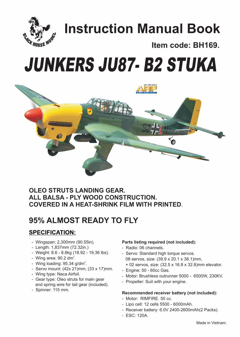
JUNKERS JU87- B2 STUKA 95% ALMOST READY TO FLY Instruction Manual Book Item code: BH169. Made in Vietnam. SPECIFICATION: - Wingspan: 2,300mm (90.55in). - Length: 1,837mm (72.32in.) - Weight: 8.6 - 8.8kg (18.92 - 19.36 lbs). 2 - Wing area: 90.2 dm . 2 - Wing loading: 95.34 g/dm . - Servo mount: (42x 21)mm; (33 x 17)mm. - Wing type: Naca Airfoil. - Gear type: Oleo struts for main gear and spring wire for tail gear (included). - Spinner: 115 mm. Parts listing required (not included): - Radio: 06 channels. - Servo: Standard high torque servos. 08 servos, size: (39.9 x 20.1 x 38.1)mm, + 02 servos, size: (32.5 x 16.8 x 32.8)mm elevator. - Engine: 50 - 60cc Gas. - Motor: Brushless outrunner 5000 - 6500W, 230KV. - Propeller: Suit with your engine. Recommended receiver battery (not included): - Motor: RIMFIRE. 50 cc. - Lipo cell: 12 cells 5500 - 6000mAh. - Receiver battery: 6.0V 2400-2600mAh(2 Packs). - ESC: 120A. OLEO STRUTS LANDING GEAR. ALL BALSA - PLY WOOD CONSTRUCTION. COVERED IN A HEAT-SHRINK FILM WITH PRINTED.
Transcript of Item code: BH169. JUNKERS JU87- B2 STUKA · 3 To avoid scratching your new airplane, do not unwrap...
JUNKERS JU87- B2 STUKA
95% ALMOST READY TO FLY
Instruction Manual BookItem code: BH169.
Made in Vietnam.
SPECIFICATION:
- Wingspan: 2,300mm (90.55in).- Length: 1,837mm (72.32in.) - Weight: 8.6 - 8.8kg (18.92 - 19.36 lbs).
2- Wing area: 90.2 dm .2
- Wing loading: 95.34 g/dm .- Servo mount: (42x 21)mm; (33 x 17)mm.- Wing type: Naca Airfoil. - Gear type: Oleo struts for main gear and spring wire for tail gear (included).- Spinner: 115 mm.
Parts listing required (not included):
- Radio: 06 channels.
- Servo: Standard high torque servos.
08 servos, size: (39.9 x 20.1 x 38.1)mm,
+ 02 servos, size: (32.5 x 16.8 x 32.8)mm elevator.
- Engine: 50 - 60cc Gas.
- Motor: Brushless outrunner 5000 - 6500W, 230KV.
- Propeller: Suit with your engine.
Recommended receiver battery (not included):
- Motor: RIMFIRE. 50 cc.
- Lipo cell: 12 cells 5500 - 6000mAh.
- Receiver battery: 6.0V 2400-2600mAh(2 Packs).
- ESC: 120A.
OLEO STRUTS LANDING GEAR.ALL BALSA - PLY WOOD CONSTRUCTION.COVERED IN A HEAT-SHRINK FILM WITH PRINTED.
4Warning . . . . . . . . . . . . . . . . . . . . . . . . . . . . . 2
4Warranty . . . . . . . . . . . . . . . . . . . . . . . . . . . . . 3
4Disclaimer. . . . . . . . . . . . . . . . . . . . . . . . . . . . 3
4Suggestion . . . . . . . . . . . . . . . . . . . . . . . . . . . 3
4Note . . . . . . . . . . . . . . . . . . . . . . . . . . . . . . . . 3
4Safety precaution . . . . . . . . . . . . . . . . . . . . . . 3
4Parts listing (not included). . . . . . . . . . . . . . . . 4
4Tools & supplies needed. . . . . . . . . . . . . . . . . 4
4Symbols used throughout this instruction manual, comprise: . . . . . . . . . . . . . . . . . . . . . . . . 4
4Preparations: . . . . . . . . . . . . . . . . . . . . . . . . . 6
4Installing the ailerons and flaps. . . . . . . . . . . . 6
4Installing the ailerons and flaps servos. . . . . . 6
4Installing the control horns and linkages . . . . 8
4Installing the main landing gear . . . . . . . . . . 10
4Installing the fuselage servos . . . . . . . . . . . . 12
4Installing the fuel tank. . . . . . . . . . . . . . . . . . 13
4Installing the engine . . . . . . . . . . . . . . . . . . . 14
4Installing the throttle . . . . . . . . . . . . . . . . . . 15
4Mounting the cowl. . . . . . . . . . . . . . . . . . . . . 16
4Installing horizontal stabilizer . . . . . . . . . . . . 17
4Installation the Rudder . . . . . . . . . . . . . . . . . 20
4
4Installing the switch, receiver and battery. . . 24
4Secure the wing to the fuselage . . . . . . . . . . 25
4Plastic parts of the wing . . . . . . . . . . . . . . . . 26
4Installing cockpit fuselage. . . . . . . . . . . . . . . 26
4Installing the spinner, propeller. . . . . . . . . . . 29
4Balancing . . . . . . . . . . . . . . . . . . . . . . . . . . . 30
4Lateral balance . . . . . . . . . . . . . . . . . . . . . . . 30
4Pre-flight check. . . . . . . . . . . . . . . . . . . . . . . 30
4Control throws . . . . . . . . . . . . . . . . . . . . . . . 30
4For your radio installation basic connection for airplane and adjustment of servos. . . . . . . . . . . 31
4Horizontal stabilizer struts . . . . . . . . . . . . . . 18
Installing the tail gear . . . . . . . . . . . . . . . . . . 22
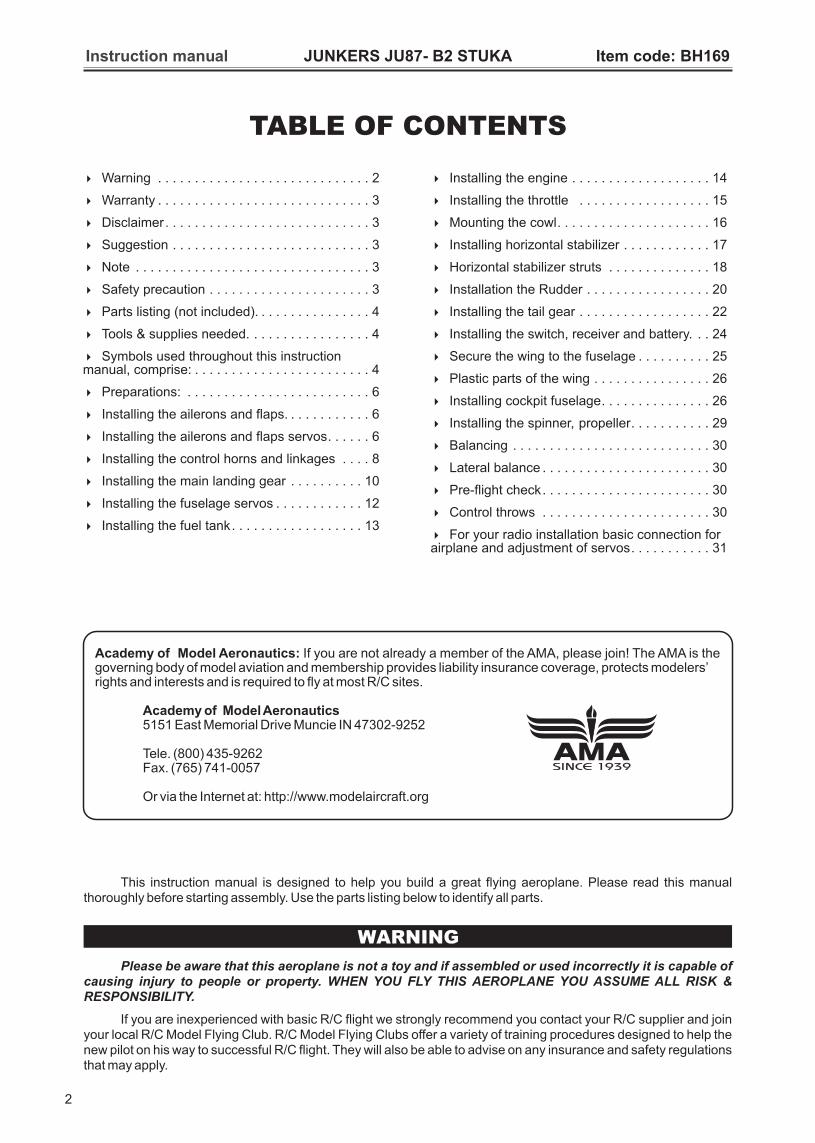
TABLE OF CONTENTS
Academy of Model Aeronautics: If you are not already a member of the AMA, please join! The AMA is the governing body of model aviation and membership provides liability insurance coverage, protects modelers’rights and interests and is required to fly at most R/C sites.
Academy of Model Aeronautics5151 East Memorial Drive Muncie IN 47302-9252
Tele. (800) 435-9262Fax. (765) 741-0057
Or via the Internet at: http://www.modelaircraft.org
SINCE 1939
2
This instruction manual is designed to help you build a great flying aeroplane. Please read this manual thoroughly before starting assembly. Use the parts listing below to identify all parts.
WARNING
Please be aware that this aeroplane is not a toy and if assembled or used incorrectly it is capable of causing injury to people or property. WHEN YOU FLY THIS AEROPLANE YOU ASSUME ALL RISK & RESPONSIBILITY.
If you are inexperienced with basic R/C flight we strongly recommend you contact your R/C supplier and join your local R/C Model Flying Club. R/C Model Flying Clubs offer a variety of training procedures designed to help the new pilot on his way to successful R/C flight. They will also be able to advise on any insurance and safety regulations that may apply.
Instruction manual JUNKERS JU87- B2 STUKA Item code: BH169
3
To avoid scratching your new airplane, do not unwrap the pieces until they are needed for assembly. Cover your workbench with an old towel or brown paper, both to protect the aircraft and to protect the table. Keep a couple of jars or bowls handy to hold the small parts after you open the bag.
SUGGESTION
Please trial fit all the parts. Make sure you have the correct parts and that they fit and are aligned properly before gluing! This will assure proper assembly. is hand made from natural materials, every plane is unique and minor adjustments may have to be made. However, you should find the fit superior and assembly simple.
The painted and plastic parts used in this kit are fuel proof. However, they are not tolerant of many harsh chemicals including the following: paint thinner, C/A glue accelerator, C/A glue debonder and acetone. Do not let these chemicals come in contact with the colors on the covering and the plastic parts.
Caution: This model is not a toy!
If you are a beginner to this type of powered model, please ask an experienced model flyer for help and support. If you attempt to operate the model without
This kit
NOTE:
Black Horse Model guarantees the component parts in this kit to be free from defects in both material and workmanship at the date of purchase by the purchaser.
This warranty does not cover cosmetic damage or damage due to acts of God, accident, misuse, abuse, negligence, commercial use, or modification of or to any part of the Product.
This warranty does not cover damage due to improper installation, operation, maintenance, or attempted repair by anyone other than Black Horse Model.
Return only the component part that is defective in materials or workmanship. Please pack the unit carefully and insure it, as this warranty does not cover loss or damage in transit.
WARRANTY
DISCLAIMER
Read this disclaimer carefully before using this product. Please strictly follow the instruction manual to assemble and use this.
In that Black Horse Model has no control over the final assembly or material used for final assembly, black Horse Model is not responsible for loss of use, or other incidental or consequential damages.
Furthermore, Black Horse Model cannot be held liable for personal injury or property damage caused by the use or misuse of Black Horse Model products. By the act of using the user-assembled products, the user accepts all resulting liability.
knowing what you are doing you could easily injure yourself or somebody else. Please keep your safety and well-being in mind at all times.
Important: Before you start construction
Even if you have built a large number of RC modelsplease read right through these instructions and check all the kit components against the parts list. We have taken great trouble to keep construction as simple as possible, without making any compromises in the area of safety.
Note regarding the film covering
Minor creases or bubbles may develop in the film covering due to major fluctuations in weather conditions (temperature, humidity etc.); in rare cases you may even find a slight warp in a component. These minor faults are in the nature of film-covered built-up wooden structures, and can easily be corrected using a heat gun, as commonly used for modelling.
Creases: Blow warm air over the area and rub down with a soft cloth.
Wing wrap: Hold the panel twisted gently in the opposite direction to the wrap, and apply warm air to remove the creases from the covering.
Caution! do not heat the film more than is absolutely necessary. If the air or the iron is too hot, the film may melt and holes may be formed.
This model is highly pre-fabricated and can be built in a very short time. However, the work which you have to carry out is important and must be done carefully. The model will only be strong and fly well if you complete your tasks competently - so please work slowly and accurately.
When self-tapping screws have to be screwed into wood, apply a little white glue to prevent them shaking loose: just squirt white glue into the hole and fit the screw
§This model is not a toy and pilots must be over the age of 14.
§Be sure that no other flyers are using your radio frequency.
§Do not smoke near fuel.
§Store fuel in a cool, dry place, away from children and pets.
§Wear safety glasses.
§The glow plug clip must be securely attached to the glow plug.
§Do not flip the propeller with your fingers.
§Keep loose clothing and wires away from the propeller.
§Do not start the engine if people are near. Do not stand in line with the side of the propeller.
§Make engine adjustments from behind the propeller only. Do not reach around the spinning propeller.
§Moisture causes damage to electronics. Avoid water exposure to all equipment not specifically designed and protected for this purpose.
SAFETY PRECAUTION:
Instruction manual JUNKERS JU87- B2 STUKA Item code: BH169
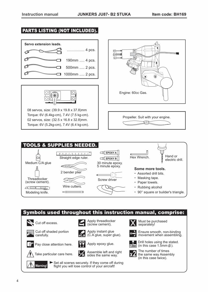
PARTS LISTING (NOT INCLUDED).
Cut off excess.
BApply epoxy glue.
Apply threadlocker(screw cement).
C.A
Apply instant glue(C.A glue, super glue).
Cut off shaded portioncarefully.
Assemble left and rightsides the same way.
Must be purchasedseparately!
Ensure smooth, non-binding movement when assembling.
Warning!Set all scerws securely. If they come off during flight you will lose control of your aircraft!
Pay close attention here.Drill holes using the stated.(in this case 1.5mm ).1.5mm
Take particular care here.The number of timesthe same way Assembly (in this case twice).
2
Symbols used throughout this instruction manual, comprise:
Wire cutters.
Hex Wrench.
Threadlocker(screw cement).
Hand orelectric drill.
cm 12345678910
Straight edge ruler.
Some more tools. Assorted drill bits.
Masking tape.
Paper towels.
Rubbing alcohol
90° square or builder's triangle.
Screw driver
Medium C/A glue
EPOXY A
EPOXY B
30 minute epoxy.5 minute epoxy.
Modeling knife.
2 bender plier
TOOLS & SUPPLIES NEEDED.
Propeller Suit with your engine..
4
Engine: 60cc Gas.
08 servos, size: (39.9 x 19.8 x 37.8)mm
Torque: 6V (6.4kg-cm), 7.4V (7.5 kg-cm).
02 servos, size: (32.5 x 16.8 x 32.8)mm.
Torque: 6V (5.2kg-cm), 7.4V (6.4 kg-cm).
Instruction manual JUNKERS JU87- B2 STUKA Item code: BH169
Servo extension leads.
190mm ..... 4 pcs.
................. pcs. 4
500mm ..... 2 pcs.
1000mm ..... 2 pcs.

Instruction manual JUNKERS JU87- B2 STUKA Item code: BH169
2x10mm Screw - - - - 32
130mm Push rod - - 6
M3
- - 10
- - 203mm Nut
Horn - - - 10
- - - - 10
- - - - 63x16mm Cap Screw
- 10Spring
5mm Washer
- - - - - - - 4
5mm Mount Nut
- - - - - - - 4
- - 45x70mm Cap Screw
- - - - 414x40mm Aluminum
5mm Spring Washer - - - - - - - 4 3x15mm Screw
- - - - - 4
- - - - - - - 4
550mm Pushrod wire - - 1
500mm Pushrod wire - - 1
Connector - - - - 1 - - - - - 4
- - - 4
1100mm Cable - - 2
- - - - - 13x35mm Cap Screw
65mm Push rod - - 2
- - - - - 23x20mm Cap Screw
3x12mm Cap Screw
- - - - 10
3x12mm Screw - - - - 4
: Fuselage.
: Wing panel ( )
: Horizontal stabilizer (3a, 3b).
: Rudder.
: Aluminium wing dihedral brace.
: Aluminium tube horizontal stabilizer
: Cockpit fuselage (7a, 7b: : Pilot,
7d: Cockpit, 7e: Top hatch fuselage).
Fuel Tank (8a : Clunk; 8b : Stopper (three line)).
: Plastic parts of the wing.
: Horizontal stabilizer struts.
:
2a, 2b .
Canopy, 7c
:
Tail gear set
1
2
3
4
5
6
7
8
7
9
8a
8b8
7e
7 7a
7d
7c
7b
:
: Cowling.
: Spinner.
Plastic and wood parts of the horizontal stabilizer.
: Plastic fairing for landing gear.
: Wheel pants.
: Oleo Strut
: Wheels.
13
14
15
16
12
11
10
4mm Spring Washer - - - - - - - 4
4mm Washer
- - - - - - - 4
1100mm Cable - - 2
- - - 4
- - 2
M3 - - 2
- - - 23mm Nut- 2Spring
- - - - - 43x15mm Cap Screw
- - 34mm Colar
11
- - - - - - 2
3mm Nut- - - 2
4mm Washer
- - - - - - - 4
4mm Spring Washer
- - - - - - - 6
- - - - - 83x12mm Cap Screw
- - - 2
10
12
17
18
1
2a
2b
3a3b
4
6
5
17
9
- - 4
18
4mm Washer - - - - 8
4mm Spring Washer - - - - - - - 8
4x20mm Cap Screw - - 8 - - - - - - - - - 2
Collar
5mm Washer - - - - 2
5x45mm Cap Screw - - 2 - - -
3x10mm Screw - 8 - - -
3x15mm Screw - 8 - - -
13a 13b
14a 14b
15
16
5

INSTALLING THE AILERONS AND FLAPS.
B
Aileron
Bottom view
Flaps
Flaps
B
INSTALLING THE AILERONS AND FLAPS SERVOS.
1. Install the rubber grommets and brass eyelets
onto the aileron servos.
2. Using a modeling knife, remove the covering
from over the pre-cut servo arm exit hole on the
aileron servo tray / hatch. This hole will allow the
servo arm to pass through when installing the aileron
pushrods.
3. Place the servo into the servo tray. Center the
servo within the tray and drill 1.5mm pilot holes
through the block of wood for each of the four
mounting screws provided with the servo.
4. Using the thread as a guide and using masking
tape, tape the servo lead to the end of the thread:
carefully pull the thread out. When you have pulled
the servo lead out, remove the masking tape and the
servo lead from the thread.
5. Place the servo into the servo tray/ hatch into the
servo box on the bottom of the wing and drill 1.5mm
pilot holes through the tray and servo box for each of
the four mounting screws. Secure the servo tray in
place using the mounting screws provided.
6. Repeat step # 2 - # 5 to install the second aileron
servo in the opposite wing half.
Instruction manual JUNKERS JU87- B2 STUKA Item code: BH169
6

o60
Flap
o90
Aileron
2x10mm Screw4 For Flap.
For Aileron.
1.5mm
2mm
4 For Flap.
For Aileron.
Screw
approx.16mm
2mm
6Aileron and flap servos.
6
1.5mm
1.5mm
2 x 10mm Screw - - - - 24
Warning!
For Aileron servo.For Flap servo.
Instruction manual JUNKERS JU87- B2 STUKA Item code: BH169
2x10mm
2x10mm
1
2
For Aileron.
Tie the string.
Pull out servo cord with string.
1
2
Bottom view
7
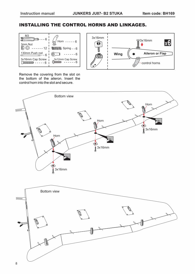
INSTALLING THE CONTROL HORNS AND LINKAGES.
Bottom view
Instruction manual JUNKERS JU87- B2 STUKA Item code: BH169
Bottom view
Horn
3x16mm
Horn
3x16mm
Horn
3x16mm
Remove the covering from the slot on the bottom of the aileron. Insert the control horn into the slot and secure.
Aileron or FlapWing
control horns
3x16mm6
3x16mm
8
130mm Push rod - - 6
M3
- - - 6
- - - - - - 12
3mm NutHorn - - - - - 6
- - - - - - 6
3x12mm Cap Screw- - - - - - 6 - - - - - 6
3x16mm Cap Screw
- - 6Spring

Spring
M3
Servo arm
3mm Nut
Push rod
Instruction manual JUNKERS JU87- B2 STUKA Item code: BH169
Horn
3x12mmSecure
9
Instruction manual JUNKERS JU87- B2 STUKA Item code: BH169
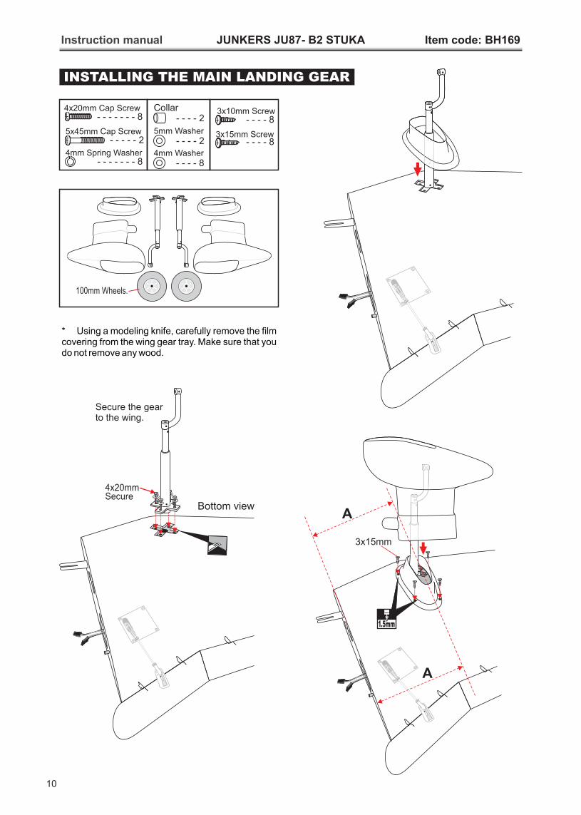
INSTALLING THE MAIN LANDING GEAR
100mm Wheels.
4mm Washer - - - - 8
4mm Spring Washer - - - - - - - 8
4x20mm Cap Screw - - 8 - - - - - - - - - 2
Collar
5mm Washer - - - - 2
5x45mm Cap Screw - - 2 - - -
3x10mm Screw - 8 - - -
3x15mm Screw - 8 - - -
Secure the gearto the wing.
4x20mmSecure
Bottom view
* Using a modeling knife, carefully remove the film covering from the wing gear tray. Make sure that you do not remove any wood.
10
3x15mm
1.5mm
A
A
Instruction manual JUNKERS JU87- B2 STUKA Item code: BH169
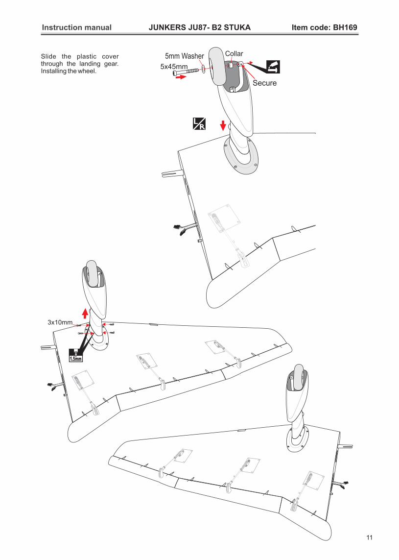
Slide the plastic cover through the landing gear. Installing the wheel.
1.5mm
3x10mm
5x45mm
5mm Washer Collar
Secure
11
Instruction manual JUNKERS JU87- B2 STUKA Item code: BH169
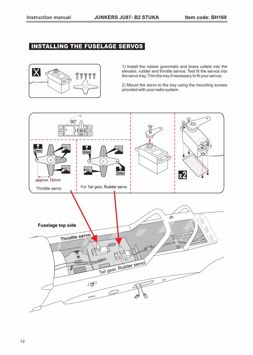
INSTALLING THE FUSELAGE SERVOS
1) Install the rubber grommets and brass collets into the elevator, rudder and throttle servos. Test fit the servos into the servo tray. Trim the tray if necessary to fit your servos.
2) Mount the servo to the tray using the mounting screws provided with your radio system.
Fuselage top side
Throttle servo
Tail gear, Rudder servo
o90
approx.16mm
2mm
2
2mm
2mm
For Tail gear, Rudder servoThrottle servo
12
Instruction manual JUNKERS JU87- B2 STUKA Item code: BH169
To carburetorfuel inlet
(see front view of fuel tank). Insert and tighten the screw.
Be sure to equip air vent pipe.
Tubing forre-fuelling
Not included.Tygon tubing (Gas). Andsilicone tubing (Methanol).
5mm
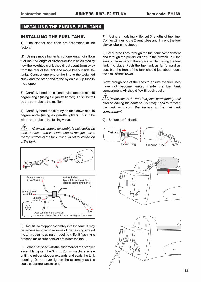
INSTALLING THE FUEL TANK.
1) The stopper has been pre-assembled at the
factory.
2) Using a modeling knife, cut one length of silicon
fuel line (the length of silicon fuel line is calculated by
how the weighted clunk should rest about 8mm away
from the rear of the tank and move freely inside the
tank). Connect one end of the line to the weighted
clunk and the other end to the nylon pick up tube in
the stopper.
3) Carefully bend the second nylon tube up at a 45
degree angle (using a cigarette lighter). This tube will
be the vent tube to the muffler.
4) Carefully bend the third nylon tube down at a 45
degree angle (using a cigarette lighter). This tube
will be vent tube to the fueling valve.
When the stopper assembly is installed in the
tank, the top of the vent tube should rest just below
the top surface of the tank. It should not touch the top
of the tank.
5) Test fit the stopper assembly into the tank. It may
be necessary to remove some of the flashing around
the tank opening using a modeling knife. If flashing is
present, make sure none of it falls into the tank.
6) When satisfied with the alignment of the stopper
assembly tighten the 3mm x 20mm machine screw
until the rubber stopper expands and seals the tank
opening. Do not over tighten the assembly as this
could cause the tank to split.
7) Using a modeling knife, cut 3 lengths of fuel line.
Connect 2 lines to the 2 vent tubes and 1 line to the fuel
pickup tube in the stopper.
8) Feed three lines through the fuel tank compartment
and through the pre-drilled hole in the firewall. Pull the
lines out from behind the engine, while guiding the fuel
tank into place. Push the fuel tank as far forward as
possible, the front of the tank should just about touch
the back of the firewall.
Blow through one of the lines to ensure the fuel lines
have not become kinked inside the fuel tank
compartment. Air should flow through easily.
Do not secure the tank into place permanently until
after balancing the airplane. You may need to remove
the tank to mount the battery in the fuel tank
compartment.
9) Secure the fuel tank.
Silicone tubeFoam ring
Fuel tank
INSTALLING THE ENGINE, FUEL TANK
13
Instruction manual JUNKERS JU87- B2 STUKA Item code: BH169
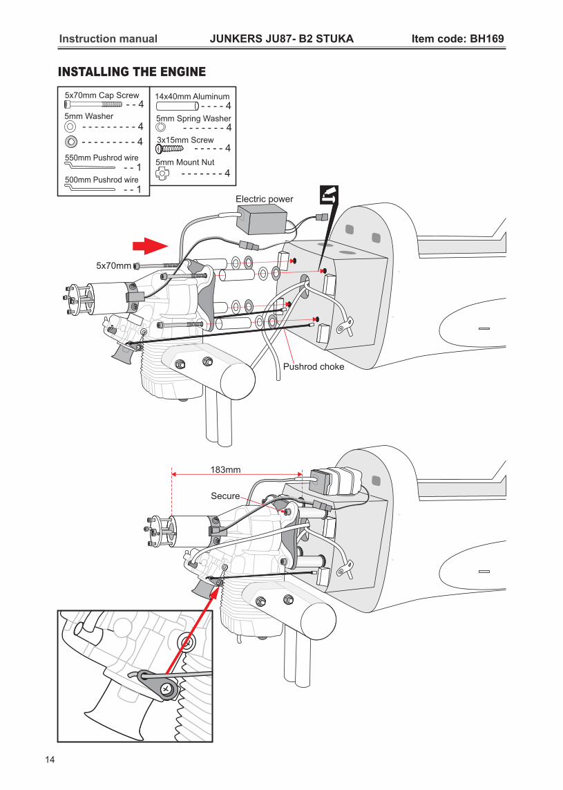
INSTALLING THE ENGINE
Secure
183mm
5x70mm
Electric power
Pushrod choke
5mm Washer
- - - - - - - - - 4
5mm Mount Nut
- - - - - - - 4
- - 45x70mm Cap Screw
- - - - 414x40mm Aluminum
5mm Spring Washer - - - - - - - 4
3x15mm Screw- - - - - 4
- - - - - - - - - 4
550mm Pushrod wire - - 1
500mm Pushrod wire - - 1
14
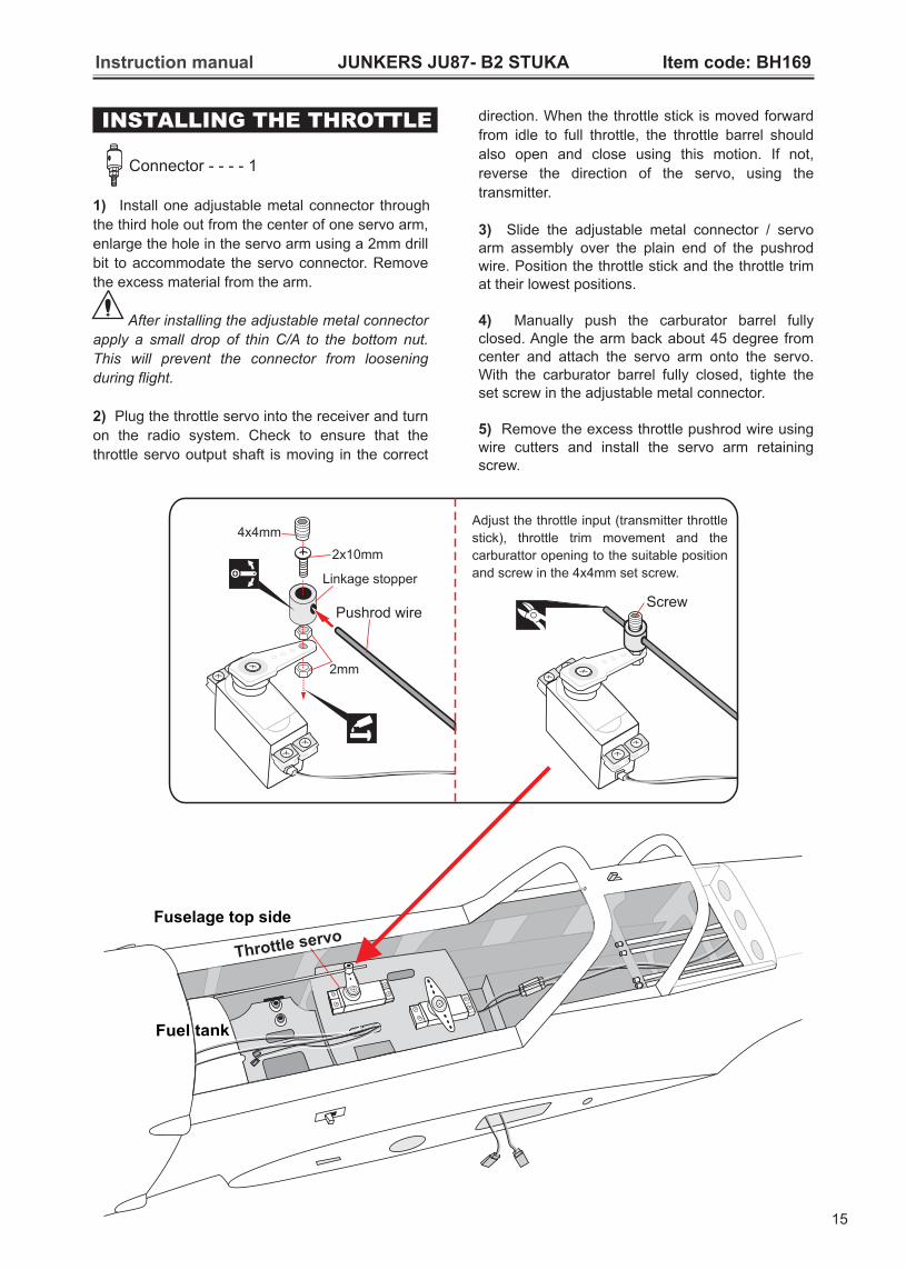
INSTALLING THE THROTTLE
Connector - - - - 1
Instruction manual JUNKERS JU87- B2 STUKA Item code: BH169
direction. When the throttle stick is moved forward
from idle to full throttle, the throttle barrel should
also open and close using this motion. If not,
reverse the direction of the servo, using the
transmitter.
3) Slide the adjustable metal connector / servo arm assembly over the plain end of the pushrod wire. Position the throttle stick and the throttle trim at their lowest positions.
4) Manually push the carburator barrel fully closed. Angle the arm back about 45 degree from center and attach the servo arm onto the servo. With the carburator barrel fully closed, tighte the set screw in the adjustable metal connector.
5) Remove the excess throttle pushrod wire using wire cutters and install the servo arm retaining screw.
1) Install one adjustable metal connector through
the third hole out from the center of one servo arm,
enlarge the hole in the servo arm using a 2mm drill
bit to accommodate the servo connector. Remove
the excess material from the arm.
After installing the adjustable metal connector
apply a small drop of thin C/A to the bottom nut.
This will prevent the connector from loosening
during flight.
2) Plug the throttle servo into the receiver and turn
on the radio system. Check to ensure that the
throttle servo output shaft is moving in the correct
Fuselage top side
Throttle servo
Fuel tank
Screw
Linkage stopper
4x4mm
2x10mm
2mm
Pushrod wire
Adjust the throttle input (transmitter throttle
stick), throttle trim movement and the
carburattor opening to the suitable position
and screw in the 4x4mm set screw.
15
Instruction manual JUNKERS JU87- B2 STUKA Item code: BH169
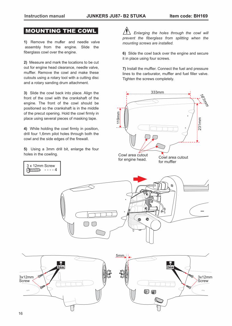
3 x 12mm Screw - - - - 4
MOUNTING THE COWL
1) Remove the muffler and needle valve
assembly from the engine. Slide the
fiberglass cowl over the engine.
2) Measure and mark the locations to be cut
out for engine head clearance, needle valve,
muffler. Remove the cowl and make these
cutouts using a rotary tool with a cutting disc
and a rotary sanding drum attachment.
3) Slide the cowl back into place. Align the
front of the cowl with the crankshaft of the
engine. The front of the cowl should be
positioned so the crankshaft is in the middle
of the precut opening. Hold the cowl firmly in
place using several pieces of masking tape.
4) While holding the cowl firmly in position,
drill four 1,6mm pilot holes through both the
cowl and the side edges of the firewall.
5) Using a 3mm drill bit, enlarge the four
holes in the cowling.
Enlarging the holes through the cowl will
prevent the fiberglass from splitting when the
mounting screws are installed.
6) Slide the cowl back over the engine and secure
it in place using four screws.
7) Install the muffler. Connect the fuel and pressure
lines to the carburator, muffler and fuel filler valve.
Tighten the screws completely.
3x12mmScrew
2mm
Cowl area cutout for muffler
Cowl area cutout for engine head.
161mm
119m
m
333mm
231m
m
16
3x12mmScrew
2mm
5mm

Instruction manual JUNKERS JU87- B2 STUKA Item code: BH169
1) Servo for H are installed the
same way as the aileron before (see page 7).
2) Control horn, linkages and for Elevator are
installed the same way as the aileron before
(see page 8, 9).
orizontal stabilizer
2x10mm
INSTALLING HORIZONTAL STABILIZER
Cut
Wood
Plastic
C.AC.A
Plastic
Plastic
65mm Push rod - - 2
M3
- - - 2
- - - - - - 4
3mm NutHorn - - - - - 2
- - - - - - 2
3x12mm Cap Screw- - - - - - 2
- - - - - 23x20mm Cap Screw
- - 2Spring2 x 10mm Screw
- - - - - - 8
12x247mm Aluminium tube.
- - - - - - - - - 1
17

Instruction manual JUNKERS JU87- B2 STUKA Item code: BH169
HORIZONTAL STABILIZER STRUTS
- - - - - - 2
3mm Nut
- - - - - - 2
4mm Washer
- - - - - - - 4
4mm Spring Washer
- - - - - - - 6
- - - - - 83x12mm Cap Screw
- - - - - - 2
Secure
C.A
C.A
18

Instruction manual JUNKERS JU87- B2 STUKA Item code: BH169
INSTALLING HORIZONTAL STABILIZER
- Attach the aluminium tube into the fuselage.- Attach the stabilizer to the fuselage.
Fuselage top side
Fuselage bottom side
Secure
19
Instruction manual JUNKERS JU87- B2 STUKA Item code: BH169
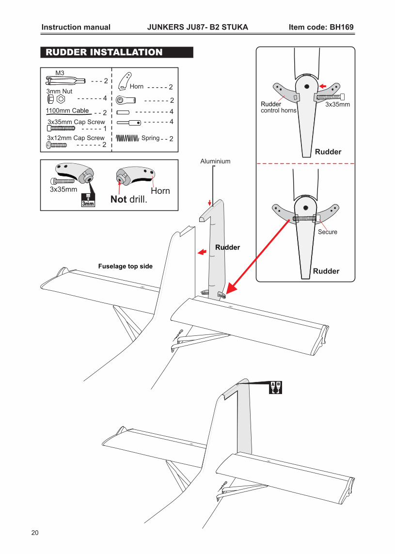
RUDDER INSTALLATION
Not drill.Horn3x35mm
3mm
Aluminium
Rudder
Fuselage top side
B
Ruddercontrol horns
3x35mm
Secure
1100mm Cable - - 2 - - 4 - - - - - -
- - 4 - - - -
M3
- - - 2
- - - - - - 43mm Nut
Horn - - - - - 2
- - - - - - 2
3x12mm Cap Screw- - - - - - 2
- - - - - 13x35mm Cap Screw
- - 2Spring
20

Instruction manual JUNKERS JU87- B2 STUKA Item code: BH169
Bottom view
Open/Close
Fuselage top side
Tail gear, Rudder servo
Rudder cable
21
1
2
34
5
1
2
34
5
Rudder
Rudder cable
o90
RudderTail gear, Rudder servo
Rudder cable

Instruction manual JUNKERS JU87- B2 STUKA Item code: BH169
INSTALLING THE TAIL GEAR
Secure
3x15mmSecure
Tail gear cable
47mm Wheels.
4mm Spring Washer - - - - - - - 4
4mm Washer
- - - - - - - 4
1100mm Cable - - 2
- - 4 - - - - - -
- - 2 - - - -
M3
- - - 2
- - - - - - 23mm Nut
- - 2Spring
- - - - - 43x15mm Cap Screw
- - 3 - - 4mm Colar
4mmColar
22
Instruction manual JUNKERS JU87- B2 STUKA Item code: BH169
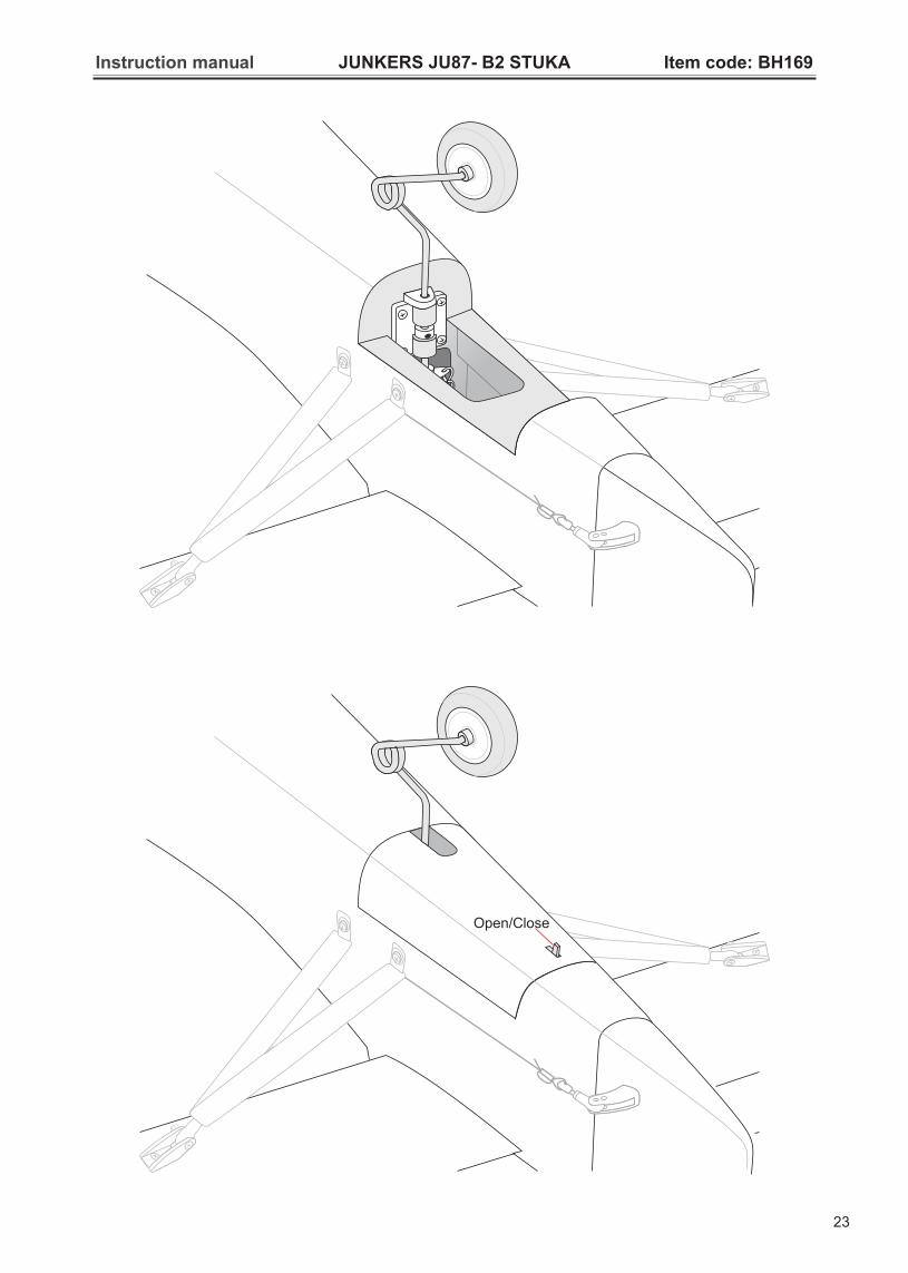
Open/Close
23
Instruction manual JUNKERS JU87- B2 STUKA Item code: BH169
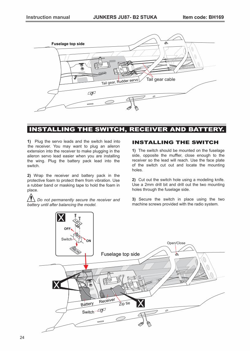
Fuselage top side
Tail gear, Rudder servo Tail gear cable
INSTALLING THE SWITCH
1) The switch should be mounted on the fuselage side, opposite the muffler, close enough to the receiver so the lead will reach. Use the face plate of the switch cut out and locate the mounting holes.
2) Cut out the switch hole using a modeling knife. Use a 2mm drill bit and drill out the two mounting holes through the fuselage side.
3) Secure the switch in place using the two machine screws provided with the radio system.
1) Plug the servo leads and the switch lead into the receiver. You may want to plug an aileron extension into the receiver to make plugging in the aileron servo lead easier when you are installing the wing. Plug the battery pack lead into the switch.
2) Wrap the receiver and battery pack in the protective foam to protect them from vibration. Use a rubber band or masking tape to hold the foam in place.
Do not permanently secure the receiver and battery until after balancing the model.
Switch ON
OFF
Fuselage top side
Receiver
Battery
Switch
Zip tie
24
INSTALLING THE RECEIVER AND BATTERY.SWITCH,
Instruction manual JUNKERS JU87- B2 STUKA Item code: BH169
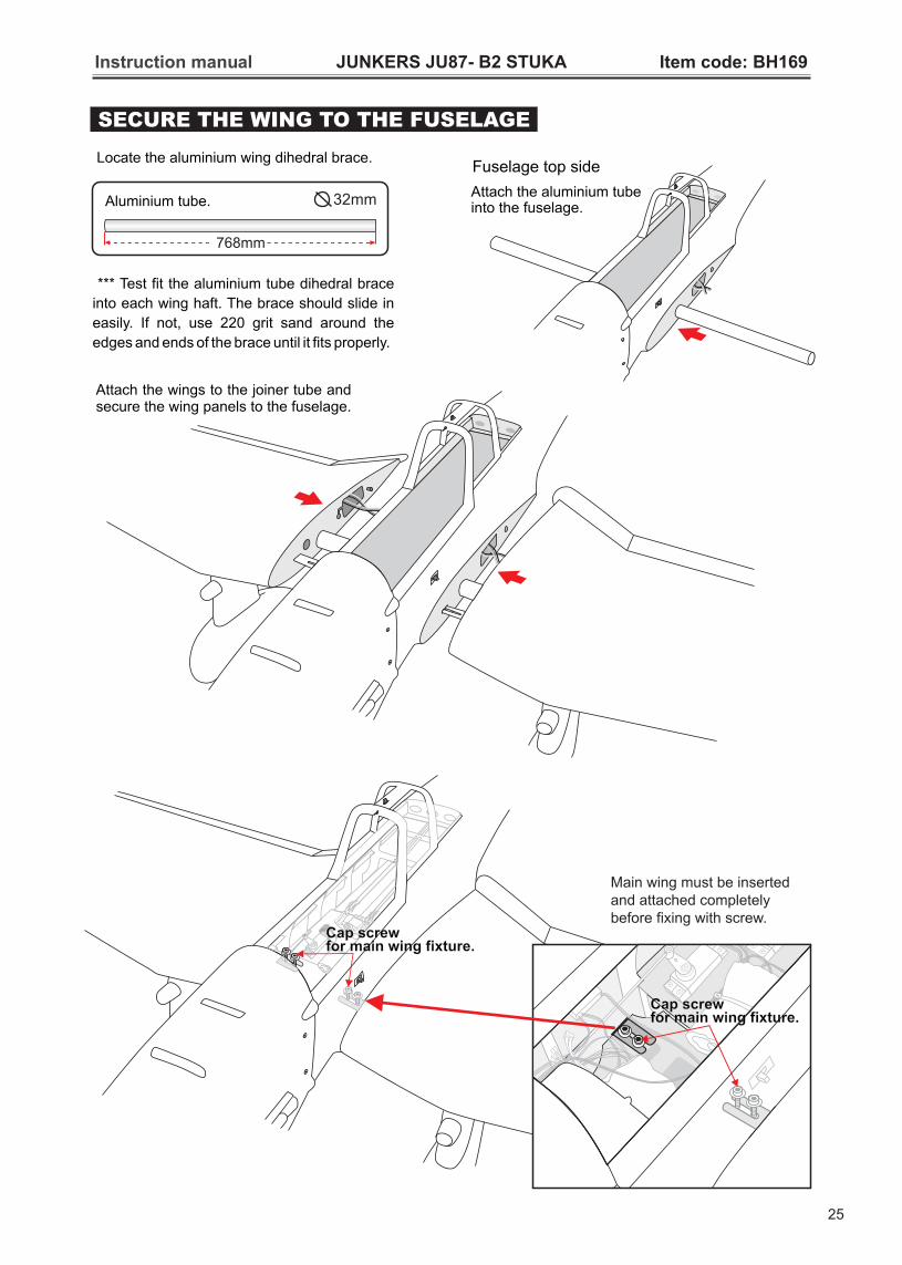
768mm
Aluminium tube. 32mm
Attach the wings to the joiner tube and secure the wing panels to the fuselage.
*** Test fit the aluminium tube dihedral brace
into each wing haft. The brace should slide in
easily. If not, use 220 grit sand around the
edges and ends of the brace until it fits properly.
SECURE THE WING TO THE FUSELAGE
Locate the aluminium wing dihedral brace.
Main wing must be insertedand attached completely before fixing with screw.
Cap screw for main wing fixture.
Cap screw for main wing fixture.
Fuselage top side
Attach the aluminium tube into the fuselage.
25
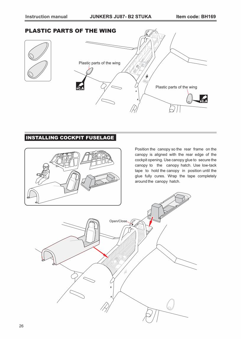
PLASTIC PARTS OF THE WING
Instruction manual JUNKERS JU87- B2 STUKA Item code: BH169
C.A
C.A
Plastic parts of the wing
Plastic parts of the wing
Position the canopy so the rear frame on the
canopy is aligned with the rear edge of the
cockpit opening. Use canopy glue to secure the
canopy to the canopy hatch. Use low-tack
tape to hold the canopy in position until the
glue fully cures. Wrap the tape completely
around the canopy hatch.
INSTALLING COCKPIT FUSELAGE
26

Instruction manual JUNKERS JU87- B2 STUKA Item code: BH169
C.A
27
Canopy glue
B
Cut
Instruction manual JUNKERS JU87- B2 STUKA Item code: BH169
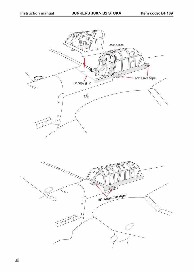
Adhesive tape.
28
Adhesive tape.
Canopy glue
Instruction manual JUNKERS JU87- B2 STUKA Item code: BH169
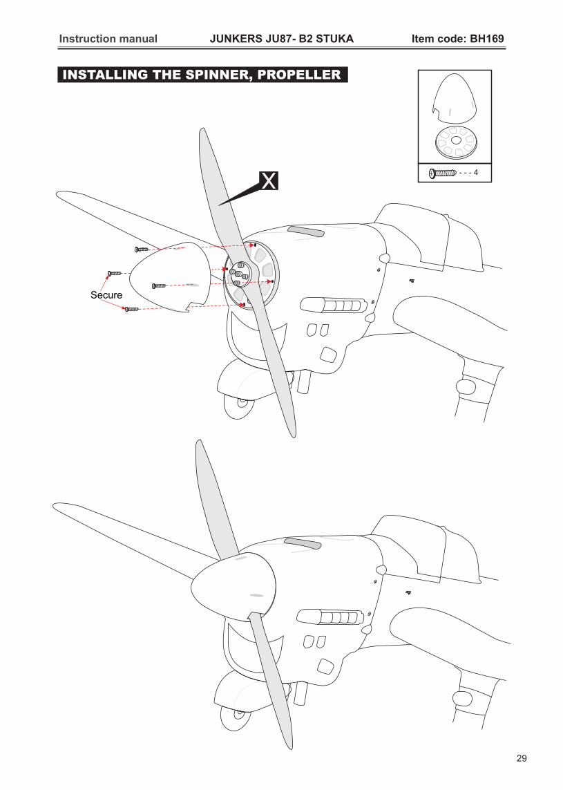
INSTALLING THE SPINNER, PROPELLER
Secure
- - - 4
29

BALANCING
1) It is critical that your airplane be balanced
correctly. Improper balance will cause your plane to
lose control and crash.
THE CENTER OF GRAVITY IS LOCATED 130MM
BACK FROM THE LEADING EDGE OF THE WING.
2) Mount the wing to the fuselage. Using a couple of
pieces of masking tape, place them on the top side of
the wing 130mm back from the leading edge, at the
fuselage sides.
3) Turn the airplane upside down. Place your fingers
on the masking tape and carefully lift the plane.
4)
AT THE FUSELAGE. BALANCE A PLANE UPSIDE
DOWN WITH THE FUEL TANK EMPTY.
If the nose of the plane falls, the plane is nose
heavy. To correct this first move the battery pack
further back in the fuselage. If this is not possible or
does not correct it, stick small amounts of lead
weight on the fuselage under the horizontal
stabilizer. If the tail of the plane falls, the plane is tail
heavy. To correct this, move the battery and receiver
forward or if this is not possible, stick weight into the
firewall. When balanced correctly, the airplane
should sit level or slightly nose down when you lift it
up with your fingers.
LATERAL BALANCE
After you have balanced a plane on the C.G. You should laterally balance it. Doing this will help the airplane track straighter.
1) Turn the airplane upside down. Attach one loop
of heavy string to the engine crankshaft and one to
the tail wheel wire. With the wings level, carefully
lift the airplane by the string. This may require two
people to make it easier.
1) We highly recommend setting up a plane using the
control throws listed.
2) The control throws should be measured at the
widest point of each control surface.
3) Check to be sure the control surfaces move in the
correct directions.
CONTROL THROWS
? Aileron: 12 m m up mm down
? Elevator: mm up mm down
? Rudder: mm right mm left
12
10 10
30 30
? Flap: 20mm
Low rate:
PRE-FLIGHT CHECK
1) Completely charge your transmitter and receiver
batteries before your first day of flying.
2) Check every bolt and every glue joint in your
plane to ensure that everything is tight and well
bonded.
3) Double check the balance of the airplane.
4) Check the control surface.
5) Check the receiver antenna. It should be fully
extended and not coiled up inside the fuselage.
6) Properly balance the propeller.
2) If one side of the wing fall, that side is heavier than the opposite. Add small amounts of lead weight to the bottom side of the lighter wing half's wing tip. Follow this procedure until the wing stays level when you lift the airplane.
Instruction manual JUNKERS JU87- B2 STUKA Item code: BH169
12mmAileron control
12mm
10mm
10mmElevator
30mm
30mmRudder control
20mmFlap
? Aileron: 16 m m up 16 mm down
? Elevator: 12 mm up 12 mm down
? Rudder: 35 mm right 35 mm left
? Flap: 25mm
High rate:
30
130mmC G
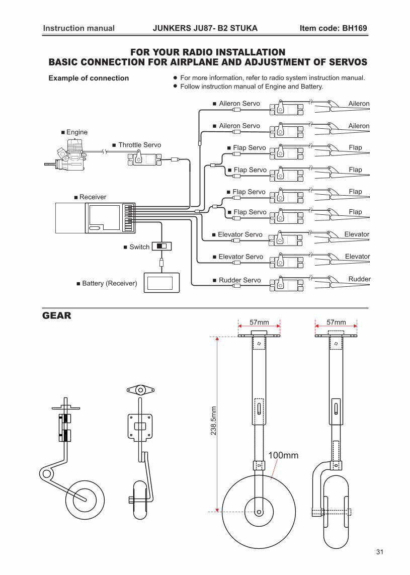
Example of connection
FOR YOUR RADIO INSTALLATIONBASIC CONNECTION FOR AIRPLANE AND ADJUSTMENT OF SERVOS
For more information, refer to radio system instruction manual.
Follow instruction manual of Engine and Battery.
GEAR
Instruction manual JUNKERS JU87- B2 STUKA Item code: BH169
57mm
100mm
23
8.5
mm
57mm
31
Engine
Throttle Servo
Receiver
Battery (Receiver)
Switch
Aileron
Aileron
Aileron Servo
Aileron Servo
ElevatorElevator Servo
Rudder Servo Rudder
FlapFlap Servo
ElevatorElevator Servo
FlapFlap Servo
FlapFlap Servo
FlapFlap Servo
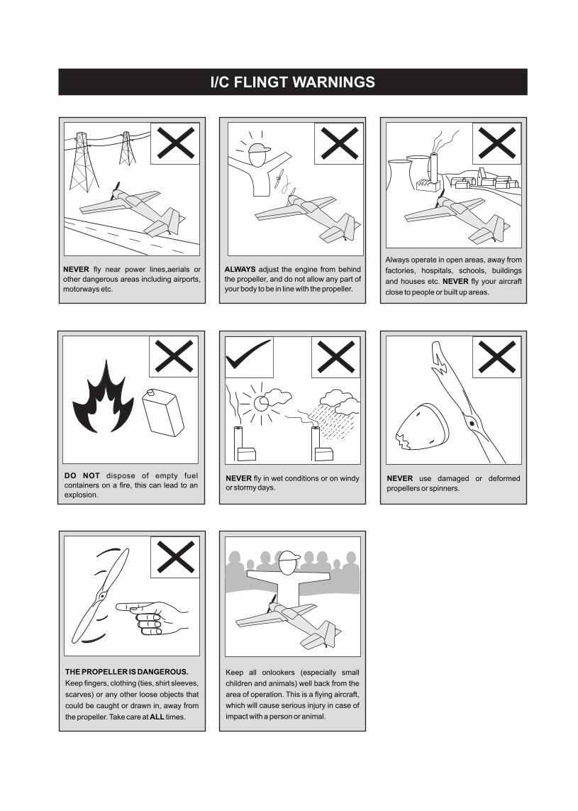
I/C FLINGT WARNINGS
NEVER fly near power lines,aerials or
other dangerous areas including airports,
motorways etc.
ALWAYS adjust the engine from behind
the propeller, and do not allow any part of
your body to be in line with the propeller.
Always operate in open areas, away from
factories, hospitals, schools, buildings
and houses etc. NEVER fly your aircraft
close to people or built up areas.
DO NOT dispose of empty fuel
containers on a fire, this can lead to an
explosion.
NEVER fly in wet conditions or on windy or stormy days.
NEVER use damaged or deformed
propellers or spinners.
THE PROPELLER IS DANGEROUS.
Keep fingers, clothing (ties, shirt sleeves,
scarves) or any other loose objects that
could be caught or drawn in, away from
the propeller. Take care at ALL times.
Keep all onlookers (especially small
children and animals) well back from the
area of operation. This is a flying aircraft,
which will cause serious injury in case of
impact with a person or animal.

I/C FLINGT GUIDELINES
Made in Vietnam
ALWAYS take off into the wind.
When ready to fly, first extend
the transmitter aerial.
Operate the control sticks on the transmitter and check that the control surfaces move freely and in the CORRECT directions.
ALWAYS land the model INTO the wind, this ensures that the model lands at the slowest possible speed.
Switch on the transmitter.
OFF - ON
OFF - ON
Check that the wings are correctly fitted to the fuselage.
If the model does not respond correctly to the controls, land it as soon as possible and correct the fault.
Empty the fuel tank after flying, fuel left in the tank can cause corrosion and lead to engine problems.
Check that the transmitter batteries have adequate power.
Switch on the receiver.
OFF - ON
Switch off the receiver.
OFF - ON
Switch off the transmitter.
OFF - ON
OFF - ON


![[Airlife Publishing] [Combat Legend] Ju 87 Stuka](https://static.fdocuments.net/doc/165x107/5530228d5503466c578b469d/airlife-publishing-combat-legend-ju-87-stuka.jpg)