ITC 220 Locomotive Transceiver - CalAmp
32
ITC 220 Locomotive Transceiver HIGH PERFORMANCE WIRELESS FOR RAILROAD PTC Installation Guide PN 133971 Rev. A Revised July 2012
Transcript of ITC 220 Locomotive Transceiver - CalAmp
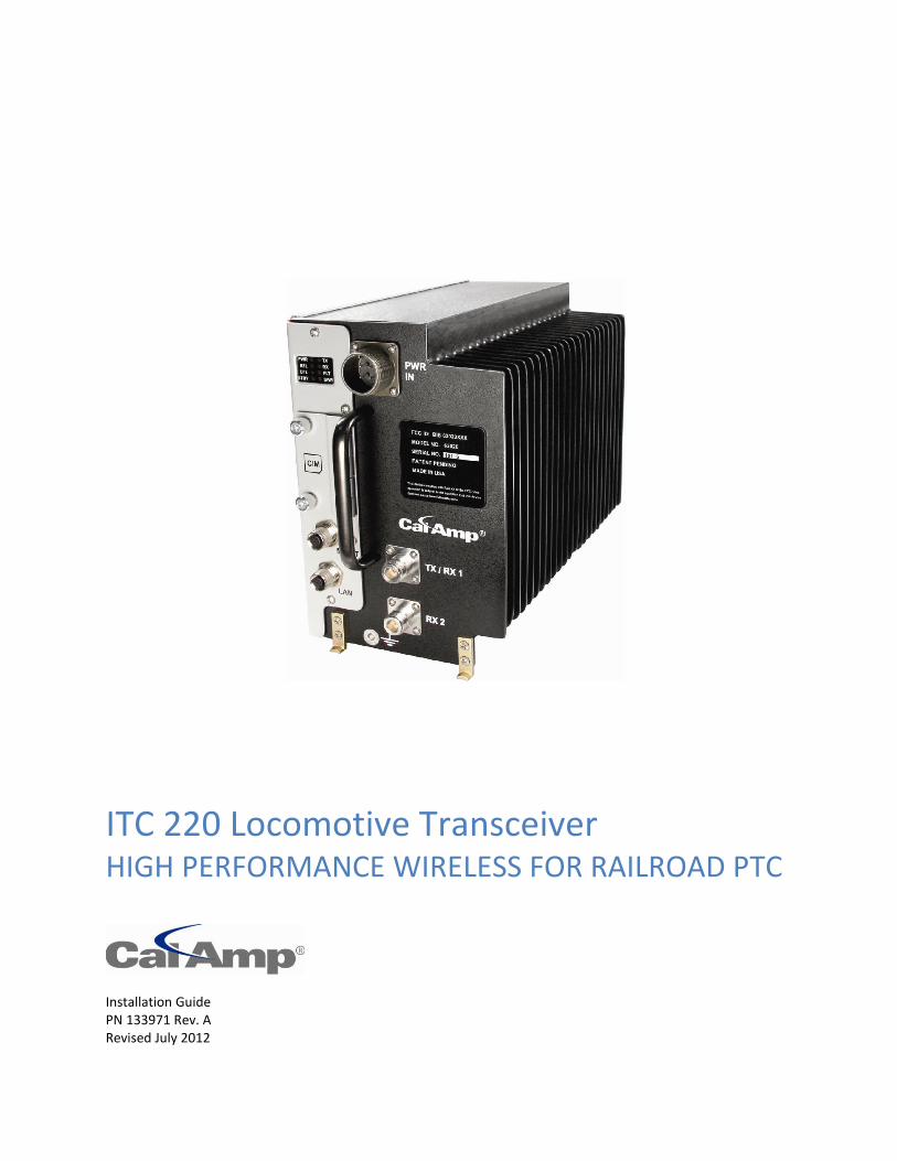
ITC 220 Locomotive Transceiver HIGH PERFORMANCE WIRELESS FOR RAILROAD PTC
Installation Guide PN 133971 Rev. A Revised July 2012

REVISION HISTORY
REV DATE REVISION DETAILS
A July 2012 Initial release. Part number 133971.

ITC 220 Locomotive Transceiver Installation Guide PN 133971 Rev. A | Page i
Important Notice Because of the nature of wireless communication, transmission and reception of data can never be guaranteed. Data may be delayed, corrupted (i.e. have errors), or be totally lost. Significant delays or losses of data are rare when wireless devices such as CalAmp provides are used in a normal manner with a well-constructed network. These products should not be used in situations where failure to transmit or receive data could result in damage of any kind to the user or any other party, including but not limited to personal injury or death, or loss of property. CalAmp accepts no responsibility for damages of any kind resulting from delays or errors in data transmitted or received using the ITC 220 Base Station, Locomotive, or Wayside Transceiver, or for failure to transmit or receive such data.
Copyright Notice © Copyright 2012 CalAmp. All rights reserved.
Products offered may contain software proprietary to CalAmp or other parties. The offer of supply of these products and services does not include or infer any transfer of ownership. No part of the documentation or information supplied may be divulged to any third party without the express written consent of CalAmp.
CalAmp reserves the right to update its products, software, or documentation without obligation to notify any individual or entity. Product updates may result in differences between the information provided in this manual and the product shipped. For access to the most current product documentation and application notes, visit www.calamp.com.
RF Exposure Compliance Requirements The ITC 220 Base Station, Locomotive, and Wayside Transceivers are intended for use in the railroad industry as Interoperable Train Control (ITC) Radio (ITCR), which is an important component of Positive Train Control (PTC). The ITC 220 Base station, Locomotive, and Wayside Transceiver units must be professionally installed and must ensure a minimum separation distance between the antenna or radiating structure and any person. Refer to Table 1 and 2 on pages 3 and 4 of the RF Energy Exposure Guide for ITC 220 Base Station, Locomotive, and Wayside Transceivers Installed in Vehicles or at Fixed Sites for
recommended minimum lateral distance, as applicable for the antenna application, type of antenna, and transmitting power.
Radio Transceiver Model Antenna application Section and applicable table
ITC 220 Base Station Transceiver Fixed installation Section 6 Fixed Installations; Table 2 on Page 5
ITC 220 Locomotive Transceiver Mobile installation Section 4 Mobile Installations; Table 1 on Page 3
ITC 220 Wayside Transceiver Fixed installation Section 6 Fixed Installations; Table 2 on Page 5
ITC 220 Wayside Transceiver Mobile installation Section 4 Mobile Installations; Table 1 on Page 3
It is the responsibility of the user to guarantee compliance with the FCC MPE regulations when operating this device in a way other than described above. The installer of this equipment must ensure the antenna is located or pointed such that it does not emit an RF field in excess of Health Canada limits for the general population.
ITC 220 Base Station, Locomotive, and Wayside Transceivers use a low power radio frequency transmitter. The concentrated energy from an antenna may pose a health hazard. People should not be in front of the antenna when the transmitter is operating.
Recommended safety guidelines for the human exposure to radio frequency electromagnetic energy are contained in the Canadian Safety Code 6 (available from Health Canada), the Federal Communications Commission (FCC) Bulletin 65 and the Council of the European Union’s Recommendation of 12 July 1999 on the limitation of exposure of the general public to electromagnetic fields (0 Hz to 300 GHz) (1999/519/EC).
Any changes or modifications not expressly approved by the party responsible for compliance (in the country where used) could void the user’s authority to operate the equipment.
ITC 220 Locomotive Transceiver Installation Guide PN 133971 Rev. A | Page ii
TABLE OF CONTENTS
1 Overview ......................................................................................................................................... 1
1.1 General Description ............................................................................................................................................... 1
1.2 Operational Characteristics .................................................................................................................................... 2
1.3 Physical Description ............................................................................................................................................... 4
1.3.1 Dimensions ................................................................................................................................................... 4
1.3.2 Connections .................................................................................................................................................. 5
1.4 Related Documents ................................................................................................................................................ 5
2 Follow Established Safety Guidelines ............................................................................................. 6
2.1 Electrical Safety ...................................................................................................................................................... 6
3 Important Information for the User ............................................................................................... 6
3.1 Limiting RF Exposure .............................................................................................................................................. 6
3.2 Fixed Antenna Guidelines ...................................................................................................................................... 7
3.3 RF Interference to Residential Receivers ............................................................................................................... 7
3.4 Equipment Modifications ....................................................................................................................................... 7
4 Locomotive Transmitter Operation ................................................................................................ 8
4.1 Locomotive Transceiver Channelization and Frequency Range ............................................................................. 8
4.2 Locomotive Channel Restrictions ........................................................................................................................... 8
4.3 Locomotive-Radiated Power Limits ....................................................................................................................... 8
5 Routine Maintenance ..................................................................................................................... 9
6 Installation .................................................................................................................................... 10
6.1 Required Equipment ............................................................................................................................................ 11
6.2 Unpack and Inspect the Unit ................................................................................................................................ 11
6.3 Confirm SD Memory Card (CIM) is Installed and Seated ..................................................................................... 11
6.4 Mount the Locomotive Transceiver ..................................................................................................................... 12
6.5 Ground the Radio Transceiver Chassis ................................................................................................................. 14
6.6 Connect Current-Limiting Circuit Protection ........................................................................................................ 14
6.7 Connect RF Antennas ........................................................................................................................................... 14
6.7.1 Antenna Planning ........................................................................................................................................ 14
6.7.2 Connect Antenna Cable(s) for Narrowband RF Antenna(s) ........................................................................ 14
6.8 Connect the Ethernet Cable ................................................................................................................................. 15
6.9 Connect the Power Cable ..................................................................................................................................... 16
ITC 220 Locomotive Transceiver Installation Guide PN 133971 Rev. A | Page iii
6.10 Power On the Transceiver .................................................................................................................................... 17
6.10.1 LED Diagnostics ........................................................................................................................................... 18
6.10.2 Verify LAN Ethernet Port is Operational ..................................................................................................... 18
7 Troubleshooting ............................................................................................................................ 19
7.1 Guidelines for Troubleshooting Common Problems ............................................................................................ 19
7.2 Power Problems ................................................................................................................................................... 19
7.3 SD Memory Card Problems .................................................................................................................................. 20
7.4 Antenna Problems................................................................................................................................................ 20
7.5 Transmission Problems ........................................................................................................................................ 21
7.6 Reception Problems ............................................................................................................................................. 22
7.7 Ethernet Connectivity Problems .......................................................................................................................... 22
7.8 RF Link Problems .................................................................................................................................................. 23
APPENDIX A — Abbreviations and Definitions ................................................................................... 24
APPENDIX B — Possible Antenna Configurations .............................................................................. 26

ITC 220 Locomotive Transceiver Installation Guide PN 133971 Rev. A | Page 1
1 OVERVIEW
This ITC 220 Locomotive Transceiver Installation Guide provides important electrical safety and radio-frequency
compliance information, operation and routine maintenance instructions, and installation and troubleshooting
procedures for CalAmp ITC 220 Locomotive Transceivers.
This manual provides essential information for personnel who perform the following on the Locomotive Transceiver:
Operation and routine maintenance (Chapters 1–5; Appendix A)
Installation and verification of operation (Chapters 1–6; Appendices A–B)
Basic troubleshooting (Chapters 1–7; Appendices A–B)
Prerequisites for users of this manual who perform the above include:
Ability to work with standard radio-frequency (RF) equipment, including knowledge of how to prevent personal
injury and equipment damage.
Ability to install LSI-rack compatible components into an LSI rack inside the compartment of a locomotive cab.
Familiarity with means to limit RF exposure from antennas and familiarity with the RF Energy Exposure Guide for ITC
220 Base Station, Locomotive, and Wayside Transceivers Installed in Vehicles or at Fixed Sites.
1.1 GENERAL DESCRIPTION
Positive Train Control (PTC) is a technology solution that prevents train-to-train collisions, over-speed derailments,
movement of a train through a switch left in the wrong position, and incursion of trains into maintenance of way work
limits. Interoperable Train Control (ITC) defines industry-standard messaging and communication protocols that
support PTC and ensure interoperability between components.
CalAmp’s line of ITC 220 Radio Transceivers for locomotive, base station, and wayside applications are manufactured
specifically for use by North American Railroads for PTC applications. Operating between 217.6 and 222 MHz, these
multi-channel software-defined radio transceivers meet railroad requirements for ITC and are designed to meet
relevant railroad specifications for operation in the harshest environments. With high power capacity, CalAmp’s ITC
220 Radio Transceivers provide wireless packet data transport between locomotives, base stations, and wayside
locations.
Locomotive Transceivers are remote radios installed in the cab of locomotives and are the mobile element of the ITC
220 network. A Locomotive Transceiver communicates with the Back Office through a Base Station over a 220 MHz RF
link. To establish this link, a Locomotive transceiver registers with the Base transceiver. As long as the Base is the best
link available, the locomotive will continue to communicate with the Back Office through that Base. The Base Station
Transceiver, Locomotive Transceiver, and Wayside Transceiver form the transportation backbone on which a
messaging application provides communication capabilities between railroad assets and their back offices.
Experience the advantage of high performance reliability designed to meet:
AAR Standard S-5702
ANSI/TIA-603-C-2004
MIL-STD-810E
American Recovery and Reinvestment Act – Buy American Provision
ITC 220 Locomotive Transceiver Installation Guide PN 133971 Rev. A | Page 2
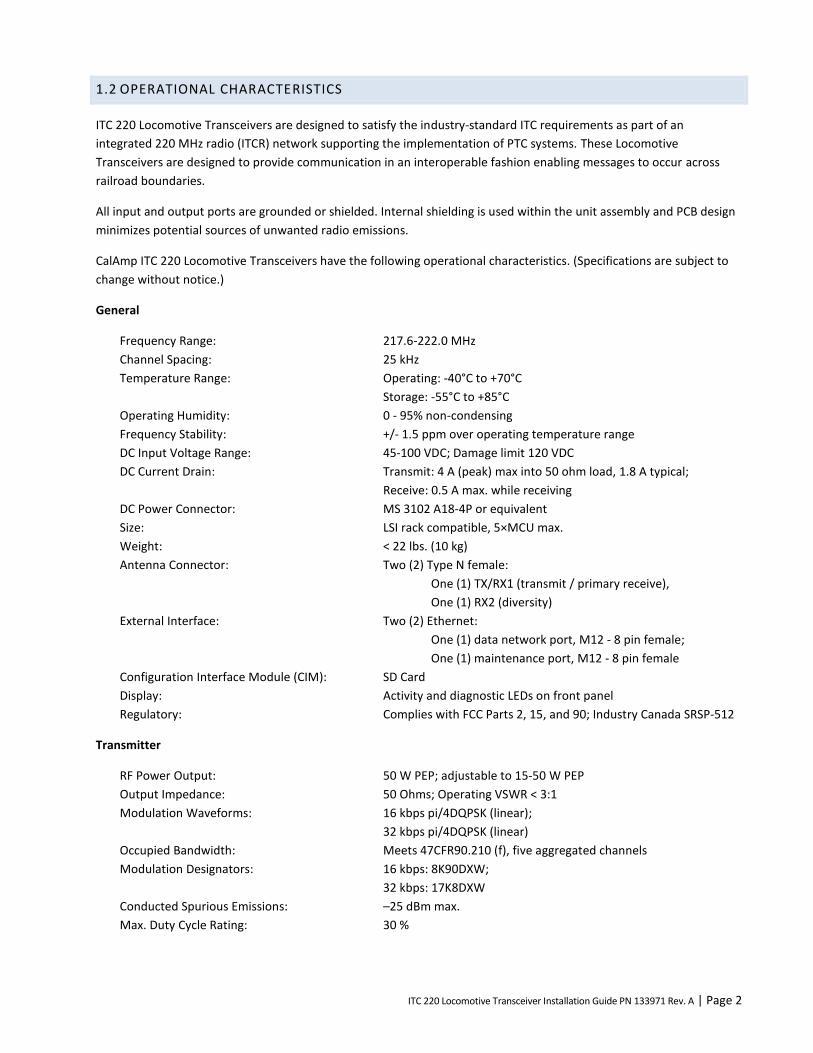
1.2 OPERATIONAL CHARACTERISTICS
ITC 220 Locomotive Transceivers are designed to satisfy the industry-standard ITC requirements as part of an
integrated 220 MHz radio (ITCR) network supporting the implementation of PTC systems. These Locomotive
Transceivers are designed to provide communication in an interoperable fashion enabling messages to occur across
railroad boundaries.
All input and output ports are grounded or shielded. Internal shielding is used within the unit assembly and PCB design
minimizes potential sources of unwanted radio emissions.
CalAmp ITC 220 Locomotive Transceivers have the following operational characteristics. (Specifications are subject to
change without notice.)
General
Frequency Range: 217.6-222.0 MHz
Channel Spacing: 25 kHz
Temperature Range: Operating: -40°C to +70°C
Storage: -55°C to +85°C
Operating Humidity: 0 - 95% non-condensing
Frequency Stability: +/- 1.5 ppm over operating temperature range
DC Input Voltage Range: 45-100 VDC; Damage limit 120 VDC
DC Current Drain: Transmit: 4 A (peak) max into 50 ohm load, 1.8 A typical;
Receive: 0.5 A max. while receiving
DC Power Connector: MS 3102 A18-4P or equivalent
Size: LSI rack compatible, 5×MCU max.
Weight: < 22 lbs. (10 kg)
Antenna Connector: Two (2) Type N female:
One (1) TX/RX1 (transmit / primary receive),
One (1) RX2 (diversity)
External Interface: Two (2) Ethernet:
One (1) data network port, M12 - 8 pin female;
One (1) maintenance port, M12 - 8 pin female
Configuration Interface Module (CIM): SD Card
Display: Activity and diagnostic LEDs on front panel
Regulatory: Complies with FCC Parts 2, 15, and 90; Industry Canada SRSP-512
Transmitter
RF Power Output: 50 W PEP; adjustable to 15-50 W PEP
Output Impedance: 50 Ohms; Operating VSWR < 3:1
Modulation Waveforms: 16 kbps pi/4DQPSK (linear);
32 kbps pi/4DQPSK (linear)
Occupied Bandwidth: Meets 47CFR90.210 (f), five aggregated channels
Modulation Designators: 16 kbps: 8K90DXW;
32 kbps: 17K8DXW
Conducted Spurious Emissions: –25 dBm max.
Max. Duty Cycle Rating: 30 %
ITC 220 Locomotive Transceiver Installation Guide PN 133971 Rev. A | Page 3
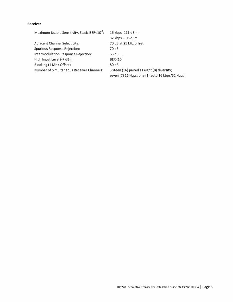
Receiver
Maximum Usable Sensitivity, Static BER<10-4
: 16 kbps -111 dBm;
32 kbps -108 dBm
Adjacent Channel Selectivity: 70 dB at 25 kHz offset
Spurious Response Rejection: 70 dB
Intermodulation Response Rejection: 65 dB
High Input Level (-7 dBm) BER<10-4
Blocking (1 MHz Offset) 80 dB
Number of Simultaneous Receiver Channels: Sixteen (16) paired as eight (8) diversity;
seven (7) 16 kbps; one (1) auto 16 kbps/32 kbps
ITC 220 Locomotive Transceiver Installation Guide PN 133971 Rev. A | Page 4
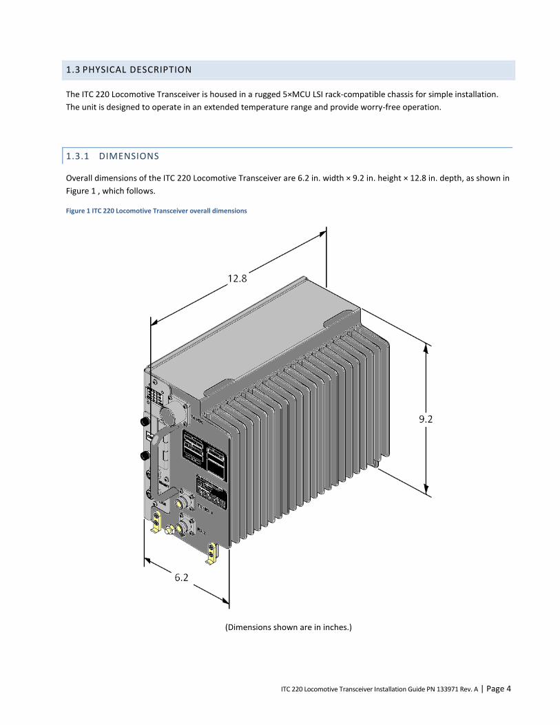
1.3 PHYSICAL DESCRIPTION
The ITC 220 Locomotive Transceiver is housed in a rugged 5×MCU LSI rack-compatible chassis for simple installation.
The unit is designed to operate in an extended temperature range and provide worry-free operation.
1.3.1 DIMENSIONS
Overall dimensions of the ITC 220 Locomotive Transceiver are 6.2 in. width × 9.2 in. height × 12.8 in. depth, as shown in
Figure 1 , which follows.
Figure 1 ITC 220 Locomotive Transceiver overall dimensions
(Dimensions shown are in inches.)
ITC 220 Locomotive Transceiver Installation Guide PN 133971 Rev. A | Page 5
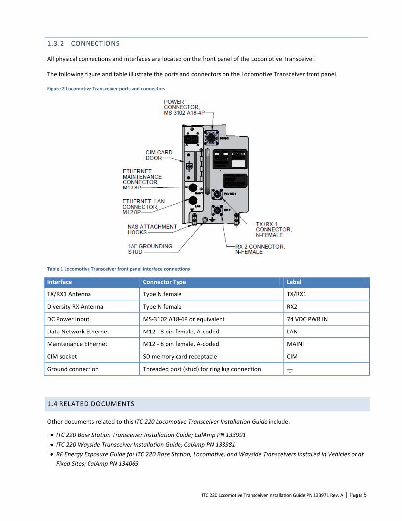
1.3.2 CONNECTIONS
All physical connections and interfaces are located on the front panel of the Locomotive Transceiver.
The following figure and table illustrate the ports and connectors on the Locomotive Transceiver front panel.
Figure 2 Locomotive Transceiver ports and connectors
Table 1 Locomotive Transceiver front panel interface connections
Interface Connector Type Label
TX/RX1 Antenna Type N female TX/RX1
Diversity RX Antenna Type N female RX2
DC Power Input MS-3102 A18-4P or equivalent 74 VDC PWR IN
Data Network Ethernet M12 - 8 pin female, A-coded LAN
Maintenance Ethernet M12 - 8 pin female, A-coded MAINT
CIM socket SD memory card receptacle CIM
Ground connection Threaded post (stud) for ring lug connection
1.4 RELATED DOCUMENTS
Other documents related to this ITC 220 Locomotive Transceiver Installation Guide include:
ITC 220 Base Station Transceiver Installation Guide; CalAmp PN 133991
ITC 220 Wayside Transceiver Installation Guide; CalAmp PN 133981
RF Energy Exposure Guide for ITC 220 Base Station, Locomotive, and Wayside Transceivers Installed in Vehicles or at
Fixed Sites; CalAmp PN 134069
ITC 220 Locomotive Transceiver Installation Guide PN 133971 Rev. A | Page 6
2 FOLLOW ESTABLISHED SAFETY GUIDELINES
Your employer has created safety guidelines that apply to your work environment and tasks. Please follow them. If you
have questions about general on-the-job safety concerns, please consult your employer’s established safety guidelines.
2.1 ELECTRICAL SAFETY
To reduce the risk of electric shock:
Follow your employer’s established electrical safety guidelines.
Disconnect power from the transceiver before removing the cover.
Be aware that removing the cover of the radio transceiver may expose you to dangerous voltages or other risks.
Avoid making internal adjustments to the radio transceiver when you are alone.
Avoid contact with a radio’s electrical components. Electric shock from voltages present with the radio transceiver
are potentially fatal.
Reassemble radio transceivers correctly. Incorrect reassembly of a radio transceiver can cause a harmful electric
shock to anyone who handles it.
3 IMPORTANT INFORMATION FOR THE USER
3.1 LIMITING RF EXPOSURE
Caution – Please refer to the RF Energy Exposure Guide for ITC 220 Base Station, Locomotive, and Wayside Transceivers Installed in Vehicles or at Fixed Sites that is packaged with each Base Station and Locomotive Transceiver and available online or by request for specific information regarding safe distances that must be maintained between personnel and energized transmitting antennas.
The information in the RF Energy Exposure Guide for ITC 220 Base Station, Locomotive, and Wayside Transceivers
Installed in Vehicles or at Fixed Sites (RF Energy Exposure Guide) is determined form FCC and Industry Canada rules
that, when followed, limit human exposure to radio frequency energy to acceptable levels. Note that although the
transceiver and antenna are expected to be sited, installed, and maintained only by professionals in a controlled-
exposure environment, the RF Energy Exposure Guide lists the larger lateral safe distances for an uncontrolled
environment. Obeying these limits will protect both railroad employees and the general public.
The Locomotive Transceiver is intended to be operated with a fixed antenna in an Occupational/Controlled Exposure
environment per FCC OET 65 or Controlled Use Environment per IC RSS-102. The Maximum Permitted Exposure (MPE)
limit for devices in the presence of the general public in the 100-300 MHz range is 0.2 mW/cm2 = 2 W/m
2 vs. 10 W/m
2
in a controlled-exposure environment.
This radio transceiver is intended for use by railroad employees who have full knowledge of their exposure and can
exercise control over their exposure to meet FCC and IC limits. This radio device is not intended for use by consumers
or the general population. Base station antennas must be positioned on towers or nonresidential buildings that are
generally unoccupied except while servicing the equipment therein.
Table 1 in Section 4 of the RF Energy Exposure Guide lists the calculated lateral distance to be maintained between the
general public and an operational transmitter antenna for the type of antenna typically used in locomotive
applications.

ITC 220 Locomotive Transceiver Installation Guide PN 133971 Rev. A | Page 7
Note – RF exposure compliance at multiple transmitter sites must be addressed on a site-by-site basis. It is the responsibility of the licensee to ensure compliance with maximum exposure limits
3.2 FIXED ANTENNA GUIDELINES
This section contains antenna information and additional notes regarding methods to limit RF exposure.
The licensee is required to comply with limits on antenna location, power, and effective antenna height per 47CFR
Subpart T §90.701 et. Seq., or Industry Canada SRSP-512 §6.3 as applicable. The section titled “Locomotive-Radiated
Power Limits,” which follows, provides additional information on how to comply with ERP limits.
Refer to the RF Energy Exposure Guide , which is packaged with each Base Station and Locomotive Transceiver and
available online or by request, for specific guidelines regarding placement and installation of fixed antennas.
Acceptable fixed-antenna types are listed in the Rated Power and Recommended Lateral Distance tables in the RF
Energy Exposure Guide.
Install antennas in accordance with the manufacturer’s instructions.
Disable the transmitter when installing or servicing its antenna or transmission line.
Maintain a safe distance from energized transmitting antennas. Refer to the table of safe distances for Base radios
in the RF Energy Exposure Guide.
Unauthorized antennas, equipment modifications, or attachments could invalidate any equipment warranty or
authority to transmit. Modification could damage the radio transceiver and may violate FCC or IC regulations.
Contact CalAmp before using other antennas.
3.3 RF INTERFERENCE TO RESIDENTIAL RECEIVERS
Notice to user: This device complies with Part 15 of the FCC Rules. Operation is subject to the condition that this device
does not cause harmful interference.
Note: this equipment has been tested and found to comply with the limits for a Class B digital device, pursuant to Part
15 of the FCC Rules. These limits are designed to provide reasonable protection against harmful interference in a
residential installation. This equipment generates, uses, and can radiate radio-frequency energy and, if not installed
and used in accordance with the instructions, may cause harmful interference to radio communications. However,
there is no guarantee that interference will not occur in a particular installation. If this equipment does cause harmful
interference to radio or television reception, which can be determined by turning the equipment off and on, the user is
encouraged to try to correct the interference by one or more of the following measures:
Reorient or relocate the receiving antenna.
Increase the separation between the equipment and receiver.
Connect the equipment to an outlet on a circuit different from that to which the receiver is connected.
Consult the dealer or an experienced radio/TV technician for help.
3.4 EQUIPMENT MODIFICATIONS
Caution – Any changes or modifications to this equipment not expressly approved by the party responsible for compliance (in the respective country of use) could void the user’s authority to operate the equipment.
ITC 220 Locomotive Transceiver Installation Guide PN 133971 Rev. A | Page 8
4 LOCOMOTIVE TRANSMITTER OPERATION
It is the responsibility of the licensee to operate this radio transmitter in compliance with FCC and Industry Canada
service rules for 220-222 MHz, namely FCC Rules Part 90 Subpart T and Industry Canada SRSP-512.
4.1 LOCOMOTIVE TRANSCEIVER CHANNELIZATION AND FREQUENCY RANGE
The Locomotive Transceiver can be configured to transmit on any one of 80 selectable 25 kHz spaced channels ranging
from 220.0125 to 221.9875 MHz inclusive. The spectrum included corresponds to all 5 kHz-wide FCC channels
numbered from 1 at 220.0025 MHz to 400 at 221.9975 MHz. Each Locomotive radio transmission occupies five of the
FCC-defined 5 kHz channels. The lowest radio channel center frequency is in the center of FCC channel 3 and the next is
centered on FCC channel 8, then 13, 18, and so on, up to the highest, which is centered with FCC channel 398.
4.2 LOCOMOTIVE CHANNEL RESTRICTIONS
Section 90.715 of the FCC Rules lists the authorized frequencies of the 400 total 5 kHz wide channels. According to
§90.733(d), these can be aggregated into larger channel widths with the exceptions of FCC channels 161-170 and 181-
185. Therefore, the radio may not transmit on those channels or their 221 MHz counterparts, 361-370 and 381-385.
This corresponds to frequencies 220.8125, 220.8375, 220.9125, 221.8125, 221.8375, and 221.9125 MHz.
Please refer to Part 90 Subpart T and SRSP-512 for additional frequency use restrictions in Canadian and Mexican
border areas.
4.3 LOCOMOTIVE-RADIATED POWER LIMITS
It is the responsibility of the licensee to comply with the effective radiated power limits based on operating
frequency, geographic location, and effective antenna height specified in 47CFR Subpart T §90.701 et. seq.,
or Industry Canada SRSP-512 §6.3, as applicable.
Important: The following supplementary antenna system information discusses means for the licensee to determine
effective radio power (ERP) and to comply with regulatory power limits.
Licensees should also note that mobile radios must limit effective radiated power (ERP) to 50 W or 10log(50) + 30 = 47
dBm PEP referenced to the 2.15 dBi gain of a dipole. The EIRP for this case is 49.15 dBm. Also note that the maximum
ERP on FCC/IC channels 196-200 at 220.975 to 221.000 MHz is 2 watts.
Antennas designed for locomotives at 220 MHz generally use a rugged cast aluminum body and are top-loaded
vertically polarized requiring a metal cab roof for a ground plane. They are necessarily electrically shorter than one-
fourth wavelength due to vertical space limitations. Maximum antenna gain is expected to be at 0 dBd – 2.15 dB.
FCC rule §90.729(b) limits mobile operation at 220-222 MHz to 50 W ERP, which is calculated relative to a free-space
dipole with 0 dBd = 2.15 dBi gain. Since the locomotive antenna has a maximum gain equal to a dipole and the rated
maximum transmitter output power is 50 W PEP, compliance with the 50 W ERP limit is assured.
The actual power will be less than 50 W ERP when the feedline and filter losses between transmitter and antenna are
taken into account. Minimum feedline loss is expected to be 0.5 dB and an inline 160 MHz reject filter adds 0.7 dB loss
for a total loss of 1.2 dB. The actual ERP is therefore 47 – 1.2 = 45.8 dBm = 38 watts. The transmitter installation cannot
be operated on FCC channels 196-200 due to the 2 W limitation.

ITC 220 Locomotive Transceiver Installation Guide PN 133971 Rev. A | Page 9
5 ROUTINE MAINTENANCE
After installation, the Locomotive Transceiver requires the following routine maintenance periodically.
Remove dust and obstructions from heat-sink fins.
Ensure that the unit is not subjected to excessive heat from adjacent equipment;
Make sure that the unit is securely mounted and supported, with specified clearance maintained above and below
heat sink fins.
Restrain cables to prevent stress on connectors.
Make sure that the SD memory card (CIM) door is securely closed.
Keep the indicator-LED panel dust-free and LEDs viewable.

ITC 220 Locomotive Transceiver Installation Guide PN 133971 Rev. A | Page 10
6 INSTALLATION
The Locomotive Transceiver is housed in a die-cast chassis that is designed to be mounted in an LSI rack (or equivalent)
and occupy less than 6×MCUs. The unit weighs less than 22 lbs. (10 kg). Overall dimensions are 6.2 in (6×MCU) width ×
9.2 in height × 12.8 in depth.
Installation of the Locomotive Transceiver consists of these steps:
1. Unpack and inspect the unit (section 6.2).
2. Confirm the SD memory card (CIM) is installed and seated (section 6.3).
3. Mount the unit (section 6.4).
4. Ground the unit (section 6.5).
5. Install current-limiting protection (section 6.6).
6. Connect the narrowband RF antennas (section 6.7).
7. Connect the Ethernet cable (section 6.8).
8. Connect the power cable (section 6.9).
9. Power on the unit (section 6.10).
At the conclusion of installation, you will verify that the Locomotive Transceiver is operational by doing the following:
1. Observe the operation of the LEDs in the transceiver front panel (section 6.10.1).
2. Verify that the LAN Ethernet port is operational (section 6.10.2).
Following sections describe each of the above steps in detail. This guide also contains a brief Troubleshooting chapter
for help with common problems that may occur when installing a Locomotive Transceiver.

ITC 220 Locomotive Transceiver Installation Guide PN 133971 Rev. A | Page 11
6.1 REQUIRED EQUIPMENT
Following is a list of equipment required to install the Locomotive Transceiver. It is expected the user is familiar with
the pieces of test equipment listed below. Instructions on how to use the following equipment are beyond the scope of
this document.
Table 2 Required equipment
Type Model Notes
Clip-on ammeter
Digital volt meter
Portable power meter
Laptop with ITC setup diagnostic software installed and running
Ethernet cable(s) Category 5 or better Ethernet cables used with the Locomotive Transceiver must be terminated one end with M12 - 8 pin male connectors one end to connect with ports on Transceiver, and RJ-45 connectors or suitable to connect with computer Ethernet ports at other end.
Torque wrench with 65-75 in.·lb. capacity
Cable ties as required
Crimping tool
6.2 UNPACK AND INSPECT THE UNIT
Unpack and inspect the Locomotive Transceiver. Note any damage that may have resulted from shipping, including
dents or loose parts. Note any damage or discrepancies between the contents in the shipping container and the
packing list.
If you detect damage or if the contents do not match the invoice, then note the defect and contact the
manufacturer.
If you do not detect any damage and the shipping invoice matches the contents, then continue with installation.
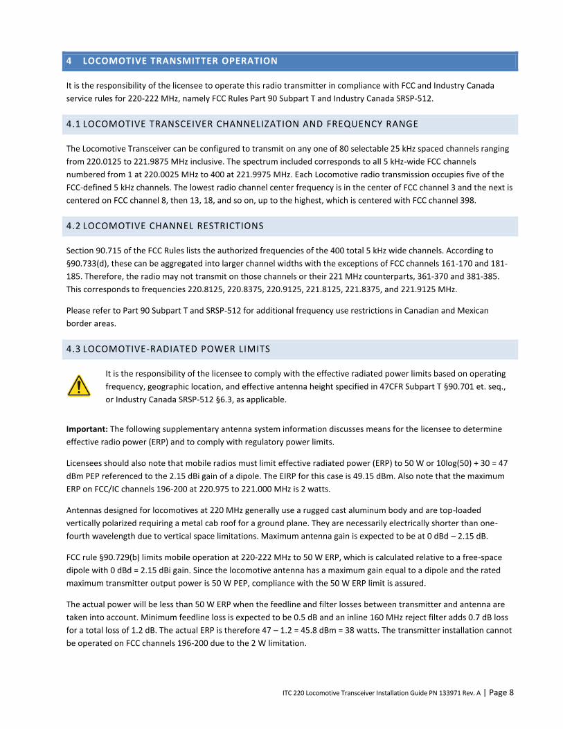
6.3 CONFIRM SD MEMORY CARD (CIM) IS INSTALLED AND SEATED
Note: The SD memory card must be inserted in the orientation shown on the door.
To confirm CIM card is installed and seated:
Open the CIM door to ensure the SD memory card is present in the CIM socket.
Push the SD memory card once to release it.
Push the SD memory card again to ensure it is seated in the socket.
Once confirmed, close and secure the CIM door.
ITC 220 Locomotive Transceiver Installation Guide PN 133971 Rev. A | Page 12
Figure 3 CIM card door on a Locomotive Transceiver
6.4 MOUNT THE LOCOMOTIVE TRANSCEIVER
The Locomotive Transceiver is installed in a standard LSI rack. The package includes mounting points for installation on
flat surfaces.
Ensure that:
The areas around the heat-sink fins are not obstructed to allow for proper airflow.
There is adequate space to access the CIM (SD memory card).
There is adequate space for cable connections.
Cables are restrained to prevent kinking and stressing connectors.
To mount the Locomotive Transceiver
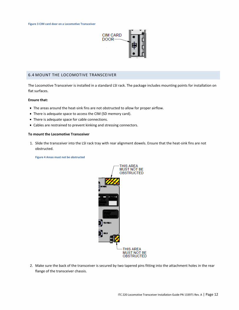
1. Slide the transceiver into the LSI rack tray with rear alignment dowels. Ensure that the heat-sink fins are not
obstructed.
Figure 4 Areas must not be obstructed
2. Make sure the back of the transceiver is secured by two tapered pins fitting into the attachment holes in the rear
flange of the transceiver chassis.
ITC 220 Locomotive Transceiver Installation Guide PN 133971 Rev. A | Page 13
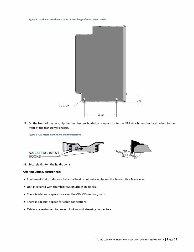
Figure 5 Location of attachment holes in rear flange of transceiver chassis
3. On the front of the rack, flip the thumbscrew hold-downs up and onto the NAS attachment hooks attached to the
front of the transceiver chassis.
Figure 6 NAS Attachment hooks and thumbscrews
4. Securely tighten the hold-downs.
After mounting, ensure that:
Equipment that produces substantial heat is not installed below the Locomotive Transceiver.
Unit is secured with thumbscrews on attaching hooks.
There is adequate space to access the CIM (SD memory card).
There is adequate space for cable connections.
Cables are restrained to prevent kinking and stressing connectors.
ITC 220 Locomotive Transceiver Installation Guide PN 133971 Rev. A | Page 14
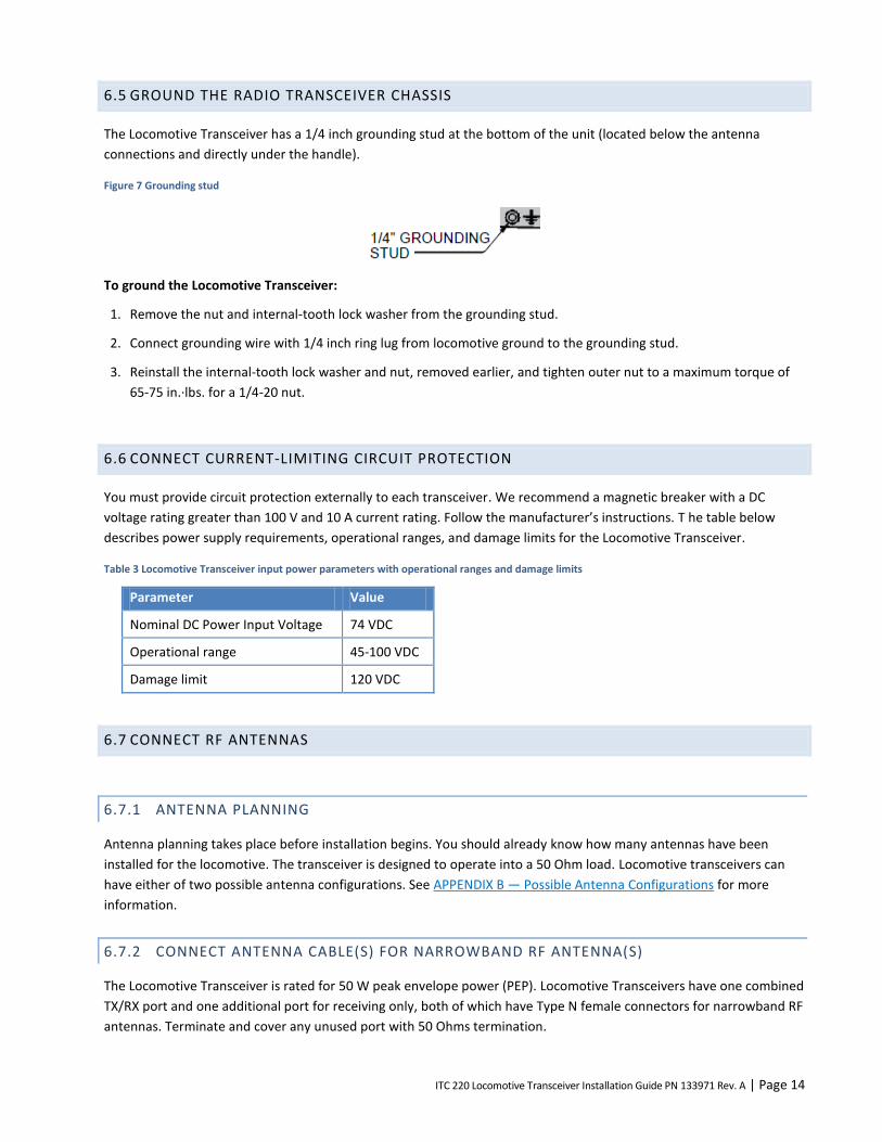
6.5 GROUND THE RADIO TRANSCEIVER CHASSIS
The Locomotive Transceiver has a 1/4 inch grounding stud at the bottom of the unit (located below the antenna
connections and directly under the handle).
Figure 7 Grounding stud
To ground the Locomotive Transceiver:
1. Remove the nut and internal-tooth lock washer from the grounding stud.
2. Connect grounding wire with 1/4 inch ring lug from locomotive ground to the grounding stud.
3. Reinstall the internal-tooth lock washer and nut, removed earlier, and tighten outer nut to a maximum torque of
65-75 in.·lbs. for a 1/4-20 nut.
6.6 CONNECT CURRENT-LIMITING CIRCUIT PROTECTION
You must provide circuit protection externally to each transceiver. We recommend a magnetic breaker with a DC
voltage rating greater than 100 V and 10 A current rating. Follow the manufacturer’s instructions. T he table below
describes power supply requirements, operational ranges, and damage limits for the Locomotive Transceiver.
Table 3 Locomotive Transceiver input power parameters with operational ranges and damage limits
Parameter Value
Nominal DC Power Input Voltage 74 VDC
Operational range 45-100 VDC
Damage limit 120 VDC
6.7 CONNECT RF ANTENNAS
6.7.1 ANTENNA PLANNING
Antenna planning takes place before installation begins. You should already know how many antennas have been
installed for the locomotive. The transceiver is designed to operate into a 50 Ohm load. Locomotive transceivers can
have either of two possible antenna configurations. See APPENDIX B — Possible Antenna Configurations for more
information.
6.7.2 CONNECT ANTENNA CABLE(S) FOR NARROWBAND RF ANTENNA(S)
The Locomotive Transceiver is rated for 50 W peak envelope power (PEP). Locomotive Transceivers have one combined
TX/RX port and one additional port for receiving only, both of which have Type N female connectors for narrowband RF
antennas. Terminate and cover any unused port with 50 Ohms termination.
ITC 220 Locomotive Transceiver Installation Guide PN 133971 Rev. A | Page 15
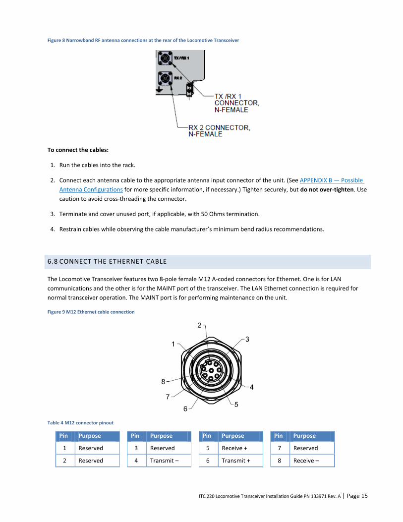
Figure 8 Narrowband RF antenna connections at the rear of the Locomotive Transceiver
To connect the cables:
1. Run the cables into the rack.
2. Connect each antenna cable to the appropriate antenna input connector of the unit. (See APPENDIX B — Possible
Antenna Configurations for more specific information, if necessary.) Tighten securely, but do not over-tighten. Use
caution to avoid cross-threading the connector.
3. Terminate and cover unused port, if applicable, with 50 Ohms termination.
4. Restrain cables while observing the cable manufacturer’s minimum bend radius recommendations.
6.8 CONNECT THE ETHERNET CABLE
The Locomotive Transceiver features two 8-pole female M12 A-coded connectors for Ethernet. One is for LAN
communications and the other is for the MAINT port of the transceiver. The LAN Ethernet connection is required for
normal transceiver operation. The MAINT port is for performing maintenance on the unit.
Figure 9 M12 Ethernet cable connection
Table 4 M12 connector pinout
Pin Purpose Pin Purpose Pin Purpose Pin Purpose
1 Reserved 3 Reserved 5 Receive + 7 Reserved
2 Reserved 4 Transmit – 6 Transmit + 8 Receive –
ITC 220 Locomotive Transceiver Installation Guide PN 133971 Rev. A | Page 16
To connect the Ethernet cable
1. Checking the orientation of the pin and slot beforehand, insert the cable into the LAN connection port of the
Locomotive Transceiver.
2. Rotate the entire connector until the locator pin engages in its slot. Carefully align the connectors and screw until
finger-tight.
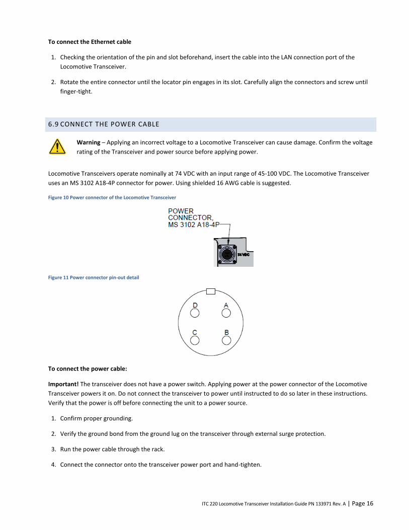
6.9 CONNECT THE POWER CABLE
Warning – Applying an incorrect voltage to a Locomotive Transceiver can cause damage. Confirm the voltage
rating of the Transceiver and power source before applying power.
Locomotive Transceivers operate nominally at 74 VDC with an input range of 45-100 VDC. The Locomotive Transceiver
uses an MS 3102 A18-4P connector for power. Using shielded 16 AWG cable is suggested.
Figure 10 Power connector of the Locomotive Transceiver
Figure 11 Power connector pin-out detail
To connect the power cable:
Important! The transceiver does not have a power switch. Applying power at the power connector of the Locomotive
Transceiver powers it on. Do not connect the transceiver to power until instructed to do so later in these instructions.
Verify that the power is off before connecting the unit to a power source.
1. Confirm proper grounding.
2. Verify the ground bond from the ground lug on the transceiver through external surge protection.
3. Run the power cable through the rack.
4. Connect the connector onto the transceiver power port and hand-tighten.
ITC 220 Locomotive Transceiver Installation Guide PN 133971 Rev. A | Page 17
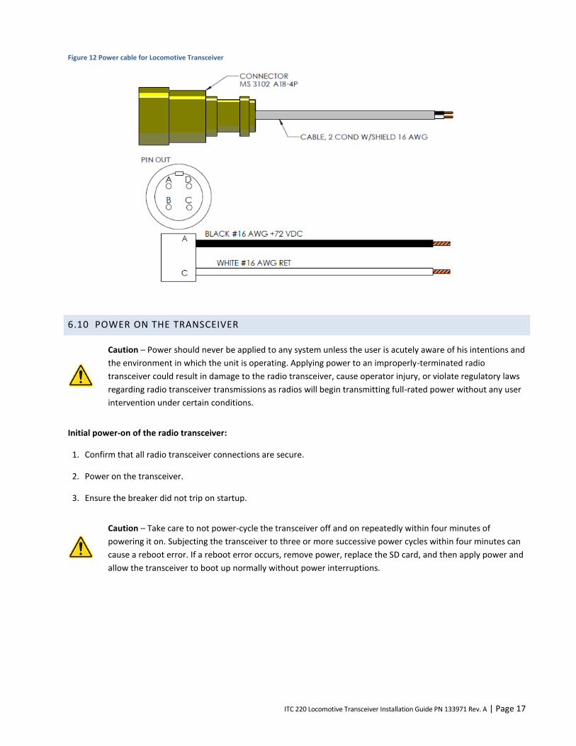
Figure 12 Power cable for Locomotive Transceiver
6.10 POWER ON THE TRANSCEIVER
Caution – Power should never be applied to any system unless the user is acutely aware of his intentions and
the environment in which the unit is operating. Applying power to an improperly-terminated radio
transceiver could result in damage to the radio transceiver, cause operator injury, or violate regulatory laws
regarding radio transceiver transmissions as radios will begin transmitting full-rated power without any user
intervention under certain conditions.
Initial power-on of the radio transceiver:
1. Confirm that all radio transceiver connections are secure.
2. Power on the transceiver.
3. Ensure the breaker did not trip on startup.
Caution – Take care to not power-cycle the transceiver off and on repeatedly within four minutes of
powering it on. Subjecting the transceiver to three or more successive power cycles within four minutes can
cause a reboot error. If a reboot error occurs, remove power, replace the SD card, and then apply power and
allow the transceiver to boot up normally without power interruptions.
ITC 220 Locomotive Transceiver Installation Guide PN 133971 Rev. A | Page 18
6.10.1 LED DIAGNOSTICS
A blinking PWR (Power) LED on the front panel indicates that the boot sequence has completed. The system becomes
active within about 25 seconds.
The front panel LEDs show the general operational status of the transceiver after it has conducted a POST, which it
does each time it boots up. Table 5 Front panel LEDs includes a description of the function of each LED as well as the
color of each LED when the transceiver is functioning properly.
Note: If a problem occurs after the transceiver boots up, the front panel LEDs indicate the problem only after a reboot
of the transceiver (provided the problem persists).
Read the description of each LED carefully. Some LEDs, such as the PWR LED, indicate a problem when they are off.
Other LEDs, such as the FLT (Fault) and SWR, indicate a problem when they are lit.
Table 5 Front panel LEDs
Label Description Color
PWR Power — Blinking green LED indicates that the unit is on. Green
TX Illuminates when the radio transmitter is keyed. Red
SWR Illuminates when the VSWR of the TX port exceeds approximately 3:1 or if the TX forward power is not within 25% of the RF output power setting.
Red
RX Illuminates when the transceiver is receiving a valid 220 MHz PTC signal. Amber
DTL DTE Link — Illuminates when the transceiver establishes a connection to a Communication Manager (CM) through the Ethernet network port.
Amber
RFL RF Link — Illuminates when an RF link is established between two radios. Amber
STBY Standby — Illuminates when the transceiver is in standby mode, indicating TX is disabled. Red
FLT Fault — When illuminated, it indicates a variety of fault conditions not indicated by other LEDs. Possible faults indicated by the Fault LED include:
One or more internal radio supply voltages are below the minimum threshold.
The extended DC voltage to the transceiver is outside of the acceptable range.
One or more of the transceiver’s internal sensors is indicating a temperature exceeding the allowable threshold.
The transceiver failed one or more self tests at power on.
TX forward power is not within 25% of the RF output power setting.
The CIM script file is not present or has invalid or corrupt data. Information for resolving possible power supply or CIM problems are provided in the Troubleshooting chapter.
Red
6.10.2 VERIFY LAN ETHERNET PORT IS OPERATIONAL
Configure the Ethernet port (or second Ethernet port) of the test computer for connection to the Transceiver LAN port,
then connect an Ethernet cable to connect these ports. The test computer should display an active network connection
on the port (indicated in the System Tray in Windows XP) within 60 seconds.
ITC 220 Locomotive Transceiver Installation Guide PN 133971 Rev. A | Page 19
7 TROUBLESHOOTING
This section describes common problems, their possible causes, and likely solutions. It covers the following problems:
Power
SD memory card
Antenna
Transmission
Reception
Ethernet connectivity
RF link
In each of the following sections, a troubleshooting table lists solutions to these problems in the order you should try
them. Solutions that require more than one step are described in detail in Transceiver test and adjustment procedures.
7.1 GUIDELINES FOR TROUBLESHOOTING COMMON PROBLEMS
Always check these items first when a transceiver problem occurs.
Check physical connections.
Make sure that all physical connections to the transceiver are secure. This includes: Ethernet (LAN port), power,
narrowband RF antennas, and GPS.
Check that the SD card is present, seated, and contains a valid CIM script file.
Make sure that there is an SD card installed and seated that contains a valid CIM script file. Without an SD card
present and without a valid CIM script, the transceiver will not transmit and will continually reboot every few
minutes.
Check the LEDs.
Use the LEDs to determine the state of the system and whether there is a fault condition. See LED Diagnostics for
more information.
7.2 POWER PROBLEMS
Problem indicators:
There is no power to the transceiver — as indicated by the green PWR (Power) LED does not illuminate or blink.
The transceiver does not transmit.
Internal voltages are low as evidenced by low output power.
To troubleshoot transceiver power issues:
1. Make sure the power cable connectors are securely connected to the power supply and to the transceiver.
2. Make sure the power cable polarity is correct: the black wire is connected to the unit’s positive (+) terminal and
the white wire is connected to the return (–) terminal. See Figure 12 Power cable .
3. Check that the power supply is turned on. If it is off, then turn it on. Verify that the breaker does not trip on power
up.

ITC 220 Locomotive Transceiver Installation Guide PN 133971 Rev. A | Page 20
4. Adjust the power supply to within the rated operating voltage.
5. Verify that the current limit on the power supply meets the maximum current draw.
Table 6 Locomotive Transceiver input power parameters
Parameter Value
Nominal DC Power Input Voltage 74 VDC
Operational range 45-100 VDC
Damage limit 120 VDC
Current draw (while transmitting rated power)
1.8 A at 74 VDC — typical while transmitting into 50 Ohm load.
6. Replace the power cable.
7. Replace the transceiver. When replacing a transceiver, if the SD card contains a valid CIM script, remove the SD
memory card from the nonworking transceiver and insert and seat it in the replacement transceiver. The
replacement transceiver will use the CIM script on the SD memory card and its configuration will be the same as
the original transceiver.
7.3 SD MEMORY CARD PROBLEMS
SD memory card problems are one type of problem that can cause the Fault LED to illuminate.
To troubleshoot SD memory card issues:
1. Check to make sure the SD memory card is present. See Confirm SD Memory Card (CIM) is Installed and Seated. If
it is missing or defective, replace it with a new SD card that contains a valid CIM script file.
2. If the transceiver reboots every few minutes, turn off transceiver power, re-seat the SD memory card, and then
power the transceiver.
3. If the above does not remedy the problem, replace the SD memory card with one that contains a valid CIM script.
4. If replacing the SD memory card and restarting the transceiver does not turn off the Fault LED then replace the
transceiver.
7.4 ANTENNA PROBLEMS
Antenna problem indicators:
Transmissions from or to the transceiver are poor or absent.
The transceiver’s SWR LED illuminates.
To troubleshoot antenna issues:
1. Make sure the antenna cable connectors are securely connected to the antenna and to the transceiver.
If there is an unused antenna connector, make sure it is properly terminated.
ITC 220 Locomotive Transceiver Installation Guide PN 133971 Rev. A | Page 21
2. Check the antenna and antenna cable for any defects or breaks.
3. Check the cable connector and radio connector for corrosion.
4. Check cable continuity.
5. Replace the cable or connector.
6. Replace the antenna.
7. Check the transmitter output power without the antenna connected.
8. Replace the transceiver. When replacing a transceiver, if the SD card contains a valid CIM script, remove the SD
memory card from the nonworking transceiver and insert and seat it in the replacement transceiver. The
replacement transceiver will use the CIM script on the SD memory card and its configuration will be the same as
the original transceiver.
7.5 TRANSMISSION PROBLEMS
Problem indicators:
Transmissions from the transceiver are weak or intermittent.
A transceiver in the network stops receiving expected communications from the transceiver.
The TX LED does not illuminate or blink.
To troubleshoot transmission issues:
1. Make sure the transceiver is turned on and the green PWR LED illuminates and blinks.
2. Check the cable connector and the radio connector for corrosion. If there is evidence of corrosion, then replace the
connector.
3. Check to confirm the transceiver unit is not overheated.
4. Inspect the SD memory card to ensure it is seated properly in the CIM socket in the orientation shown on the door
and is not damaged.
5. Make sure there is a valid CIM script file loaded from the SD card. Without an SD card present and without a valid
CIM script, the transceiver will not transmit and will continually reboot every few minutes.
6. Make sure the antenna cable connectors are securely connected to the antenna and to the radio connectors.
7. Adjust the power output higher and lower to verify the transmission is controllable.
8. Monitor the current supplied by the power supply to confirm the current drawn is consistent with like transceiver
units operating under similar conditions.
9. Check the antenna for any defects or breaks.
10. Adjust the power supply voltage, if necessary. If the power supply voltage is too low, the transceiver might stop
transmitting.
11. Replace the cable or connector.
ITC 220 Locomotive Transceiver Installation Guide PN 133971 Rev. A | Page 22
12. Replace the transceiver. When replacing a transceiver, if the SD card contains a valid CIM script, remove the SD
memory card from the nonworking transceiver and insert and seat it in the replacement transceiver. The
replacement transceiver will use the CIM script on the SD memory card and its configuration will be the same as
the original transceiver.
7.6 RECEPTION PROBLEMS
Problem indicators
A transceiver in the network stops receiving communications from another transceiver.
The RX LED does not illuminate or blink.
To troubleshoot receiver issues:
1. Make sure the transceiver is turned on and the green PWR LED illuminates and blinks.
2. Verify the transmit frequency is within limits. See Operational Characteristics.
3. Verify the antenna cable connectors are securely connected to the antenna and the transceiver.
4. Verify each antenna is connected to the appropriate antenna input connector. Terminate unused connector, if
applicable. (See APPENDIX B — Possible Antenna Configurations for more specific information, if necessary.)
5. Check the cable connector and transceiver connector for corrosion.
6. Replace the cable or connector.
7. Check the antenna for any defects or breaks.
8. Replace the transceiver. When replacing a transceiver, if the SD card contains a valid CIM script, remove the SD
memory card from the nonworking transceiver and insert and seat it in the replacement transceiver. The
replacement transceiver will use the CIM script on the SD memory card and its configuration will be the same as
the original transceiver.
7.7 ETHERNET CONNECTIVITY PROBLEMS
Problem indicators:
The unit does not connect to the Ethernet network.
The DTE Link LED does not illuminate or blink.
To troubleshoot network connectivity issues:
1. Check network activity using a computer. If the network is down, persons responsible for the network
administration will need to restore network operation.
2. Make sure the Ethernet cable is securely connected to the transceiver LAN port.
3. Verify external network equipment is functioning properly.
4. Replace the Ethernet cable.

ITC 220 Locomotive Transceiver Installation Guide PN 133971 Rev. A | Page 23
5. Replace the transceiver. When replacing a transceiver, if the SD card contains a valid CIM script, remove the SD
memory card from the nonworking transceiver and insert and seat it in the replacement transceiver. The
replacement transceiver will use the CIM script on the SD memory card and its configuration will be the same as
the original transceiver.
7.8 RF LINK PROBLEMS
When the RF Link LED is on, it means that the Locomotive transceiver has selected and connected to a Base Station
transceiver. When the LED is off, it probably means the Locomotive transceiver detects one or more Base Station
transceivers but has not selected one.
Problem indicators:
The RFL (RF Link) LED does not illuminate or blink.
To troubleshoot RF link issues:
1. Check the antenna for any defects or breaks.
2. Make sure the transceiver is turned on and the green PWR LED illuminates and blinks.
3. Make sure the antenna cable connectors are securely connected to the antenna and to the transceiver.
4. Inspect the SD memory card to ensure it is not damaged and is seated properly in the CIM socket.
5. Make sure there is a valid CIM script file loaded from the SD card. Without an SD card present and without a valid
CIM script, the transceiver will not transmit and will continually reboot every few minutes.
6. Replace the transceiver. When replacing a transceiver, if the SD card contains a valid CIM script, remove the SD
memory card from the nonworking transceiver and insert and seat it in the replacement transceiver. The
replacement transceiver will use the CIM script on the SD memory card and its configuration will be the same as
the original transceiver.

ITC 220 Locomotive Transceiver Installation Guide PN 133971 Rev. A | Page 24
APPENDIX A — ABBREVIATIONS AND DEFINITIONS
A: Ampere, or Amp; measure of electric current
AWG: American Wire Gauge (a measure of wire
diameter)
BER: Bit Error Rate
CIM: Configuration Interface Module
cm: Centimeter
Common Channel: A CSMA-operated channel common
to all Base Station, Locomotive, and Wayside
Transceivers in the system. Every radio transceiver in
the system should have the same common channel.
CSMA: Carrier Sense Multiple Access
CW: Constant Wave
dB: Decibel
dBd: Decibel, dipole
dBi: Decibel, isotropic
dBm: Decibel, referenced to one milliwatt
DC: Direct Current
DCE: Data Communication Equipment
DTDMA: Dynamic Time Division Multiple Access
DOP Dilution of Precision
DQPSK: Differential Quaternary Phase-Shift Keying
EIA: Electronic Industries Alliance
EIRP: Equivalent Isotropically Radiated Power
ERP: Effective Radiated Power
EVM: Error Vector Magnitude
FCC: Federal Communications Commission (U.S.)
FRA: Federal Railroad Administration (U.S.)
FTDMA: Fixed Time Division Multiple Access
GPS: Global Positioning System
HAAT: Height Above Average Terrain
IC: Industry Canada (Canada)
ITC: Interoperable Train Control
ITCR: Interoperable Train Control Radio
kbps: Kilobits per Second
LAN: Local Area Network
LOS: Line of Sight
Local Channel: A frequency assigned to each Base
Transceiver (DTDMA and FTDMA) and Wayside
Transceiver (FTDMA)
LSI: Locomotive System Integration
m: Meter
Mbps: Megabits Per Second
MEO: Medium Earth Orbit
MHz: Megahertz
MPE: Maximum Permissible Exposure
MSGPS: Multi-Satellite Global Positioning System
mW: Milliwatt
NAS: An attachment system for LSI rack compatible
components that utilizes alignment pins, attachment
hooks, and thumbscrews
NIC: Network Interface Card or Network Interface
Controller
PC: Personal Computer
PCA: Printed Circuit Assembly
PCB: Printed Circuit Board
PEP: Peak Envelope Power
PER: Packet Error Rate

ITC 220 Locomotive Transceiver Installation Guide PN 133971 Rev. A | Page 25
POST: Power On Self Test
PPM: Parts Per Million
PSK: Phase Shift Keying
PSWR: Power Standing Wave Ratio
PTC: Positive Train Control
Radio ID: Radio Identifier; A unique identifier assigned
to each radio transceiver in the system
RF: Radio Frequency
RSSI: Received Signal Strength Indicator
RTCS: Radio Test Control Simulator
RX: Receive
SAR: Specific Absorption Rate
SD memory card: Secure Digital memory card
SMA connector: SubMiniature version A connector
SRSP: Standard Radio System Plan (Canada)
TCP/IP: Transmission Control Protocol / Internet
Protocol
TCXO: Temperature-Compensated Crystal Oscillator
TNC connector: Threaded Neill-Concelman connector
TX: Transmit
U: Unit measure of height for rack-mounted
equipment, defined 44.5 mm (approximately 1¾ in) for
rack-mounted equipment that conforms to EIA 19-inch
rack standards
UUT: Unit Under Test
VDC: Voltage, Direct Current
VSWR: Voltage Standing Wave Ratio
W: Watt
XtermW: The terminal-emulation application used for
configuring and testing ITC 220 Transceivers
ITC 220 Locomotive Transceiver Installation Guide PN 133971 Rev. A | Page 26
APPENDIX B — POSSIBLE ANTENNA CONFIGURATIONS
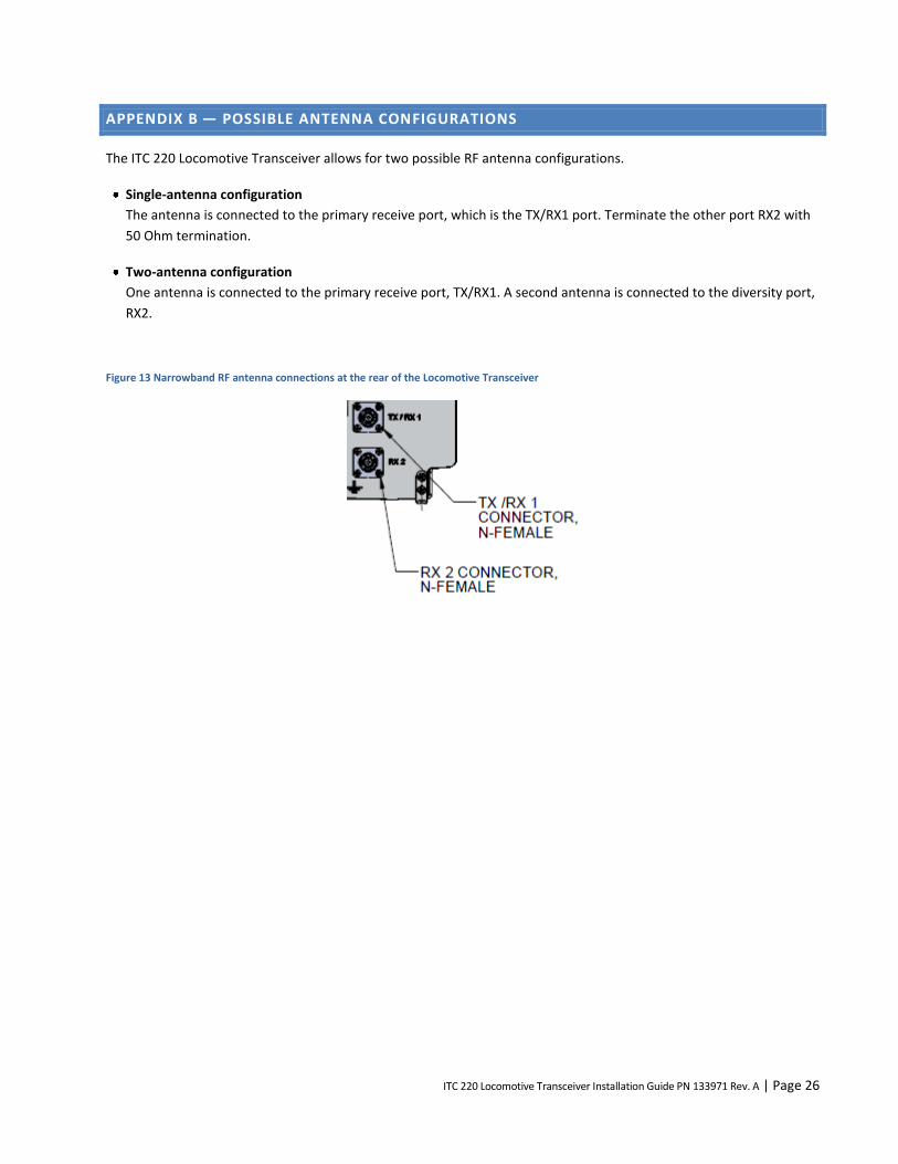
The ITC 220 Locomotive Transceiver allows for two possible RF antenna configurations.
Single-antenna configuration
The antenna is connected to the primary receive port, which is the TX/RX1 port. Terminate the other port RX2 with
50 Ohm termination.
Two-antenna configuration
One antenna is connected to the primary receive port, TX/RX1. A second antenna is connected to the diversity port,
RX2.
Figure 13 Narrowband RF antenna connections at the rear of the Locomotive Transceiver

ITC 220 Locomotive Transceiver Installation Guide PN 133971 Rev. A | Page 27
ABOUT CALAMP
CalAmp is a leading provider of wireless communications products that enable anytime/anywhere access to critical
information, data, and entertainment content. With comprehensive capabilities ranging from product design and
development through volume production, CalAmp delivers cost-effective high quality solutions to a broad array of
customers and end markets. CalAmp is the leading supplier of Direct Broadcast Satellite (DBS) outdoor customer
premise equipment to the U.S. satellite television market. The Company also provides wireless data communication
solutions for the telemetry and asset tracking markets, private wireless networks, railroad Positive Train Control (PTC)
radio transceivers, public safety communications and critical infrastructure and process control applications. For
additional information, please visit the Company’s website at www.calamp.com.