IT20495-L AutoCAD Customization Boot Camp Basic (No...
30
Page 1 IT20495-L AutoCAD Customization Boot Camp—Basic (No Experience Required) Lee Ambrosius Autodesk, Inc. Learning Objectives Learn how to create custom desktop icons Learn how to create command aliases Discover tools and tool palettes Learn how to modify the ribbon and Quick Access toolbar Description You can extend AutoCAD software in a number of ways, but many users are unsure of where or how to get started. In this lab, you will create custom desktop icons, create and modify command aliases that you can use to start commands, define tools and tool palettes, and modify the ribbon and Quick Access toolbar to reduce repetitive drawing tasks. This lab will give you a solid foundation in some of the available customization features that AutoCAD software offers to become more productive when you return to your office. This session features that are available in AutoCAD and AutoCAD LT. Your AU Expert Lee Ambrosius is a Principal Learning Experience Designer at Autodesk, Inc., for the AutoCAD software and AutoCAD LT software products. He works primarily on the CAD administration, customization, and developer documentation. Lee has also worked on the user documentation for AutoCAD on Windows and Mac. He has presented on a wide range of topics at Autodesk University over the past decade plus, from general AutoCAD customization to Autodesk ObjectARX technology. Lee has authored a number of AutoCAD-related books, with his most recent project being AutoCAD Platform Customization: User Interface, AutoLISP, VBA, and Beyond published by Wiley & Son’s. When he’s not writing, you can find him roaming various community forums, posting articles on his blog, or tweeting AutoCAD-related information. Twitter: @leeambrosius Email: [email protected] Blog: http://hyperpics.blogs.com
-
Upload
truongnguyet -
Category
Documents
-
view
220 -
download
0
Transcript of IT20495-L AutoCAD Customization Boot Camp Basic (No...

Page 1
IT20495-L
AutoCAD Customization Boot Camp—Basic (No Experience Required) Lee Ambrosius Autodesk, Inc.
Learning Objectives
Learn how to create custom desktop icons
Learn how to create command aliases
Discover tools and tool palettes
Learn how to modify the ribbon and Quick Access toolbar
Description
You can extend AutoCAD software in a number of ways, but many users are unsure of where or how to get started. In this lab, you will create custom desktop icons, create and modify command aliases that you can use to start commands, define tools and tool palettes, and modify the ribbon and Quick Access toolbar to reduce repetitive drawing tasks. This lab will give you a solid foundation in some of the available customization features that AutoCAD software offers to become more productive when you return to your office. This session features that are available in AutoCAD and AutoCAD LT.
Your AU Expert
Lee Ambrosius is a Principal Learning Experience Designer at Autodesk, Inc., for the AutoCAD software and AutoCAD LT software products. He works primarily on the CAD administration, customization, and developer documentation. Lee has also worked on the user documentation for AutoCAD on Windows and Mac. He has presented on a wide range of topics at Autodesk University over the past decade plus, from general AutoCAD customization to Autodesk ObjectARX technology. Lee has authored a number of AutoCAD-related books, with his most recent project being AutoCAD Platform Customization: User Interface, AutoLISP, VBA, and Beyond published by Wiley & Son’s. When he’s not writing, you can find him roaming various community forums, posting articles on his blog, or tweeting AutoCAD-related information.
Twitter: @leeambrosius Email: [email protected] Blog: http://hyperpics.blogs.com

Page 2
1 Introduction The AutoCAD software is an extensive 2D drafting and 3D modeling program. The functionality of AutoCAD has grown since it was first introduced over 30 years ago in 1982. What sets AutoCAD apart from many other CAD programs is its expansive capabilities of being customized or automated. Using the customization and programming features of AutoCAD, individuals and companies can simplify the everyday workflows they follow. Workflows that many seek to customize or automate are:
Initial drawing setup; layer creation, title block insertion and the population of attribute values
Extraction of design data for use downstream in a bill of materials or ordering entry system
Consumption of project information from a data source such as a spreadsheet or database
This lab provides you with the opportunity to roll-up your sleeves and get some hands-on experience with customizing and programming AutoCAD which will prepare you to apply the techniques covered back at the office. You do not need to learn how to program in order to be more productive in the everyday tasks you already perform with AutoCAD. While knowing how to program is not a requirement to customizing AutoCAD, learning how to program does provide you with a greater set of resources to automate tasks in AutoCAD.
2 Which Customization and Programming Options are Available Not all customization and programming options are created equal, some options are well integrated into the program that you might not even realize you are customizing the AutoCAD program. Creating new layers and named styles are forms of customization that many drafters perform on a daily basis, and don’t realize they are customizing the AutoCAD program. Saving layers and named styles to a drawing template can help eliminate the need to create the layers and named styles in each drawing.
The following lists many of the common customization and programming options available:
Basic
Layers
Annotation styles (text, dimensions, multileaders, and tables)
Blocks
Drawing templates
Plot styles
User profiles
Workspaces
Desktop icon customization
Command aliases
Tool palettes
Materials and visual styles
Intermediate
Scripts
User interface (CUI Editor)
Dynamic blocks
Action macros
DIESEL
Custom linetypes and hatch patterns
Custom shapes and text styles

Page 3
Advanced
AutoLISP / Visual LISP
Visual Basic for Applications (VBA)
ActiveX / COM (VBA, VBScript, VB.NET, C#, C++)
Database connectivity
Transmittal API
Managed .NET (VB.NET, C#)
ObjectARX (C++)
JavaScript
Sheet Set Manager API
Custom CAD Standards plug-ins
Forge Platform APIs
3 What You Need to Get Started Most of the customization and programming options available in AutoCAD are supported through utilities or commands found inside the program or installed with the operating system (Windows or Mac OS). It is when you want to extend the functionality of the AutoCAD program using Managed .NET or ObjectARX that you will need to purchase, download, and/or install additional software.
4 Supplemental Content See the separate IT20495-L-Ambrosius-Supplement-AU2016.docx for the supplemental content related to the exercises of this session.
5 Exercises This section contains all the exercises that will be covered during this lab or when you get back to the office.
E1 Create a Desktop Shortcut
This exercise demonstrates how to create a custom desktop shortcut to launch AutoCAD with a specific drawing template file and to set the ‘3D Basic’ workspace current.
1. Open Windows Explorer or File Explorer, and browse to C:\Datasets\IT20495-L - AutoCAD Customization Boot Camp-Basic (No Experience Required) or the location of the data files associated with this lab.
Tip: If you have a keyboard with a Windows key, press +E to launch Windows Explorer or File Explorer.
2. In the dataset folder, double-click the EX1 - Command Switches.txt file to open it in Notepad.
3. Minimize all open applications until you get to the desktop.
Tip: If you have a keyboard with a Windows key, press +M to minimize all open Windows.
4. Right-click in an empty area of the desktop and click New Shortcut.
5. In the Create Shortcut dialog box, in the Type the Location of the Item text box, type C:\ and then click Browse.

Page 4
6. In the Browse for Files or Folders dialog box, navigate to C:\Program Files\Autodesk\AutoCAD 2017 and select acad.exe. Click OK.
7. In Notepad, select the text under Target. Right-click the selected text and click Copy.
8. In the Create Shortcut dialog box, click in the Type the Location of the Item text box and press the End key.
9. Press the Spacebar once.
10. Right-click in the Type the Location of the Item text box. Click Paste to add the copied command line switches.
Note: If the dataset was placed in a different location, update the text C:\Datasets\IT20495-L - AutoCAD Customization Boot Camp-Basic (No Experience Required) in the pasted text to match the location of the dataset for this session.
Page 5
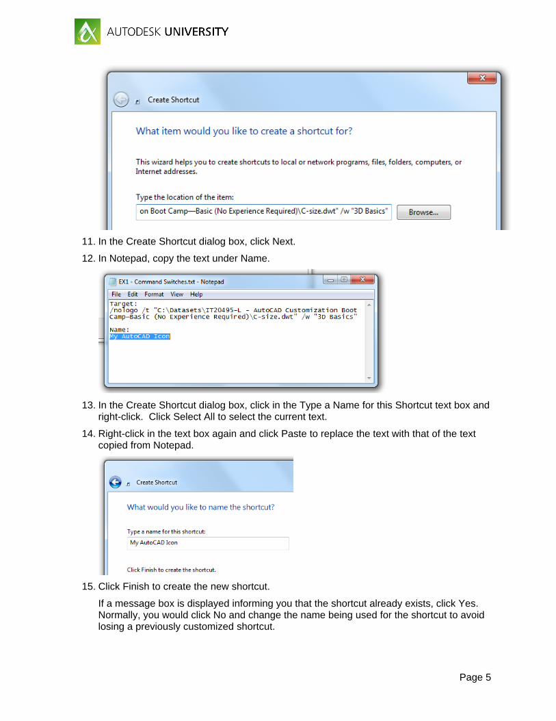
11. In the Create Shortcut dialog box, click Next.
12. In Notepad, copy the text under Name.
13. In the Create Shortcut dialog box, click in the Type a Name for this Shortcut text box and right-click. Click Select All to select the current text.
14. Right-click in the text box again and click Paste to replace the text with that of the text copied from Notepad.
15. Click Finish to create the new shortcut.
If a message box is displayed informing you that the shortcut already exists, click Yes. Normally, you would click No and change the name being used for the shortcut to avoid losing a previously customized shortcut.

Page 6
16. Double-click the My AutoCAD Icon shortcut to test it.
When AutoCAD starts, you should notice that no splash screen is displayed, the 3D Basic workspace is set current, and the default drawing file that is opened is based on the C-size.dwt drawing template file.
Note: If the drawing template file is not found, AutoCAD will start but the default drawing won’t be based on the C-size.dwt drawing template file.

Page 7
After you create a shortcut, you can modify its behavior by selecting and right-clicking the shortcut, and then clicking Properties. When the Properties dialog box is displayed, you can modify the application and command line switches previously added in the Target text box.
E2 Define Custom Command Aliases
This exercise demonstrates how to define an alias to start the REVCLOUD command, override the C alias to start the COPY command instead of CIRCLE, and create a new alias for the CIRCLE command.
1. In AutoCAD, on the ribbon, click Manage tab Customization panel Edit Aliases drop-down menu Edit Aliases.
2. In Notepad, scroll to the bottom of the file and click in the blank line under the ‘-- User Defined Command Aliases --’ section.

Page 8
3. Type the following text:
RV, *REVCLOUD C, *COPY CC, *CIRCLE
The PGP file should now look similar to the following:
; than once in this file, items in the User Defined Command Alias take ; precedence over duplicates that appear earlier in the file. ; **********----------********** ; No xlate ; DO NOT REMOVE RV, *REVCLOUD C, *COPY CC, *CIRCLE
4. In Notepad, click File menu Save.
5. Switch back to the AutoCAD program, at the Command prompt, type reinit and press Enter.
6. In the Re-initialization dialog box, click PGP File (it should now be checked) and click OK.
7. At the Command prompt, type rv and press Enter.
The REVCLOUD command should start.
8. Specify two points for the revision cloud or press Esc to cancel the REVCLOUD command.
9. Test the C and CC command aliases as well.
E3 Create a Tool Palette and Tools
This exercise explains how to create a new tool palette with some new tools.
The following steps explain how to create a new tool palette.
1. Open the Sample Drawing.dwg file from the C:\Datasets\IT20495-L - AutoCAD Customization Boot Camp-Basic (No Experience Required) folder.

Page 9
2. Display the Tool Palettes window if it is not already displayed.
On the ribbon, click View tab Palettes panel Tool Palettes.
3. On the Tool Palettes window, right-click over a tab and click New Palette.
4. In the in-place editor, type My Tools and press Enter.
Note: If the in-place editor closes and the default name is accepted, right-click the new tool palette’s tab and click Rename Palette. Type the new name and press Enter.
In these steps, you add new tools to the My Tools tool palette.
1. Click the hatch object located in the walls along the right side of the drawing. Press and
hold down the right mouse button, and then drag the cursor over the My Tools palette.

Page 10
2. Release the mouse button to create a new hatch tool based on the properties of the selected hatch object.
3. Click and drag the dimension from the left side of the drawing onto the My Tools palette.
You should now have two new tools on the My Tools palette.
4. In an empty area of the My Tools palette, right-click and click Customize Commands.
5. In the Customize User Interface editor, Command List pane, click in the Search Command List text box and type revision.
6. In the Commands list, select the Rectangular Revision Cloud command.
7. Press and hold down the left mouse button over the selected command, and then drag the cursor over the My Tools palette.
Note: You might need to move the Customize User Interface (CUI) Editor to see the Tool Palettes window.

Page 11
8. Release the mouse button to add the Command tool.
9. Click Cancel (or OK) to close the CUI Editor.
The following steps explain how to modify the properties of a tool.
1. On the Tools Palettes window, right-click over the Rectangular Revision Cloud tool and click Properties.
The Command String field in the Tool Properties dialog box contains a copy of the command macro string from the original command in the CUI Editor.
2. In the Tool Properties dialog box, General section, click the Layer field and choose RevCloud from the drop-down list.
3. Click OK to apply the change.
4. At the AutoCAD Command prompt, type explorer and press Enter.

Page 12
5. In Windows Explorer or File Explorer, navigate to the C:\Datasets\IT20495-L - AutoCAD Customization Boot Camp-Basic (No Experience Required) folder.
6. Select the Conference Table.dwg file, then drag and drop the file onto the My Tools palette.
7. Repeat the previous step for the C-Size Title Block.dwg file.
8. In AutoCAD, try each of the tools you added to the My Tools palette.
Some tools can only be clicked, while others can be clicked or dragged onto the drawing area.
Tip: Pressing the Spacebar repeats the last tool used from the Tool Palettes window.
9. Create a new drawing and try the tools again.
Notice that the objects created with the Rectangular Revision Cloud tool are placed on the RevCloud layer.

Page 13
E4 Create a Quick Access Toolbar (QAT)
This exercise explains how to create a new Quick Access toolbar (QAT) and assign it to a workspace.
In these steps, you create a new QAT and modify the commands that shown by default.
1. On the ribbon, click Manage tab Customization panel User Interface.
2. In the Customize User Interface (CUI) Editor, Customizations In pane, right-click the Quick Access Toolbars node and click New Quick Access Toolbar.
3. Rename the new toolbar by typing My QAT and pressing Enter.
Note: If you cannot change the toolbar’s name, right-click the new toolbar and click Rename.

Page 14
4. Click the plus sign next to the new toolbar and reveal the default commands that are added.
5. Right-click the Plot command and click Remove. Click Yes to confirm the deletion of the element.
6. In the Command List pane, Search Command List text box, type spell.
7. Click and drag the Spell Check command from the Command List and drop it onto the My QAT toolbar.
8. In the Command List pane, Search Command List text box, type publish.

Page 15
9. Add the Publish… command above Spell Check on the My QAT toolbar.
10. Click the Command List drop-down list and choose Ribbon Control Elements.
11. In the Search Command List text box, type layer.

Page 16
12. Add the Layer List Combo Box control after Spell Check on the My QAT toolbar.
13. Click Apply to save the changes made.
The completed Quick Access toolbar should now look like the following in the CUI Editor:

Page 17
Once a Quick Access toolbar has been created, it must be added to a workspace before it can be displayed in the AutoCAD user interface. These steps explain how to create a new workspace and add the My QAT toolbar to it.
1. In the Customize User Interface (CUI) Editor, Customizations In pane, click the plus sign next to the Workspaces node to expand it.
2. Select the Drafting & Annotation workspace.
3. Right-click over the Drafting & Annotation workspace and click Duplicate.
4. Right-click over the new workspace named Copy Of Drafting & Annotation1 and click Rename.
5. In the in-place editor, type My Workspace and press Enter.
6. Right-click over My Workspace and click Set Current.
7. In the Workspace Contents pane, click Customize Workspace.

Page 18
8. In the Customizations In pane, expand the Quick Access Toolbars node and click the check box next to My QAT.
My QAT should now be checked.
9. In the Workspace Contents pane, click Done.
10. Click OK to save the changes and exit the CUI Editor.
Note: If any message boxes are displayed, click OK to continue loading the changes to the CUIx file.

Page 19
E5 Create a Ribbon Tab and Panel
This exercise explains how to create a new ribbon panel, add commands to a ribbon panel, create a new ribbon tab to display a ribbon panel, and display a ribbon tab with a workspace.
1. On the ribbon, click Manage tab Customization panel User Interface.
2. In the Customize User Interface (CUI) Editor, Customizations In pane, click the plus sign next to the Ribbon node to expand it. Right-click the Panels node and click New Panel.
3. In the in-place text editor, type My Panel and press Enter.
Note: If you cannot change the panel’s name, right-click the new ribbon panel and click Rename.
4. In the Command List pane, Search Command List text box, type rectangular.

Page 20
5. In the Command List pane, select the Rectangular Revision Cloud command and drag it to Row 1 under the My Panel ribbon panel. Release the mouse button to add the command.
6. Select the Rectangular Revision Cloud command you just added to Row 1 of the My Panel ribbon panel.
7. In the Properties pane, click the Button Style field and select Large with Text (Vertical) from the drop-down list.
8. Click in the text box to the right of the Name field, then type Rectangular\nRevcloud and press Enter.
Note: The \n forces the label to be displayed on two lines. The \n will disappear once the field loses focus, but that is okay.
9. Add a few of your favorite commands from the Command List pane to the My Panel ribbon panel and adjust their names and button styles as desired.
10. Click Apply to save the changes.

Page 21
The following steps explain how to create a custom command and add it to the ribbon panel.
1. In the Command List pane, click Clear to remove any text in the Search Command List text box.
2. Click Create a New Command.
3. In the Properties pane, change the following values:
Command Name: Revision Number
Macro: ^C^C-LAYER;M;RevNums;C;1;;;-INSERT;REVNUM;\1;;0;
Note: A copy of the macro can be found in the EX5 - Create a Ribbon Tab and Panel.txt file that is part of the dataset.
4. Click in the Small Image field and then click the Ellipsis button […].

Page 22
5. In the Select Image File dialog box, browse to C:\Datasets\IT20495-L - AutoCAD Customization Boot Camp—Basic (No Experience Required) and select the RevNum.bmp file. Click Open.
Note: You might need to browse to a different location based on where the files for this session are stored.
6. Click in the Large Image field and type RevNum.bmp.
7. In the Command List pane, select the Revision Number command and drag it to Row 1 under the My Panel ribbon panel.
8. Select the Revision Number command you just added to Row 1 of the My Panel ribbon panel.
9. In the Properties pane, click the Button Style field and select Large with Text (Vertical) from the drop-down list.
10. Click in the text box to the right of the Name field, then type Revision\nNumber and press Enter.
11. Click Apply to save the changes.
The commands on the ribbon panel should include Rectangular Revcloud and Revision Number along with whichever commands you choose to add.

Page 23
The following explains how to create and customize a ribbon tab.
1. In the Customize User Interface (CUI) Editor, Customizations In pane, click the plus sign next to the Ribbon node to expand it. Right-click the Tabs node and click New Tab.
2. In the in-place text editor, type My Tab and press Enter.
Note: If you cannot change the tab’s name, right-click the new ribbon tab and click Rename.
3. Expand the Panels node under Ribbons.
4. Under the Panels node, right-click over the My Panel node and click Copy.

Page 24
5. Under the Tabs node, right-click over the My Tab node and click Paste.
A reference to the My Panel ribbon panel is added to the My Tab ribbon tab.
6. Click Apply to save the changes.
The following explains how to add a ribbon tab to the current workspace.
1. In the Customize User Interface (CUI) Editor, Customizations In pane, click the plus sign next to the Workspaces node to expand it.
2. Select the workspace that ends with the text (current) and click Customize Workspace.

Page 25
3. In the Customizations In pane, expand the Ribbon Tabs node and click the check box next to My Tab.
My Tab should now be checked and be added to the Ribbon Tabs node in the Workspace Contents pane.
4. In the Workspace Contents pane, click Done.
5. Click OK to save the changes and exit the CUI Editor.
Note: If any message boxes are displayed, click OK to continue loading the changes to the CUIx file.
6. On the ribbon, click the My Tab ribbon tab to see the commands on the My Panel ribbon panel.

Page 26
E6 Modify and Create a New Workspace from the AutoCAD User Interface
This exercise explains how to modify a workspace directly in the user interface and save the changes to the current workspace.
1. On the Quick Access toolbar, click the Customize button and then click Show Menu Bar.
2. On the menu bar, click Tools Toolbars AutoCAD Layers.

Page 27
3. On the Quick Access toolbar, click the Customize button and then click Hide Menu Bar.
4. On the ribbon, right-click a ribbon tab and then click Show Tabs Parametric to hide the ribbon tab.
5. On the ribbon, click the Annotate tab to set it current.
6. Click and hold the left mouse button over an empty area of the Dimensions panel and drag it to the left of the Text panel. Release the mouse button to reposition the Dimensions panel.

Page 28
7. On the ribbon, click View tab Palettes panel Properties.
The Properties palette should now be displayed.
8. If the Tool Palettes window is closed, open it.
9. On the status bar, click Workspace Switching Save Current As.
10. In the Save Workspace dialog box, click the drop-down list and choose My Workspace.
11. Click Save. When prompted to replace the workspace, click Replace.
Page 29
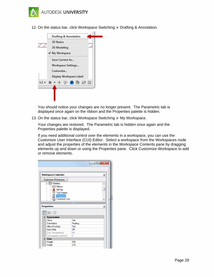
12. On the status bar, click Workspace Switching Drafting & Annotation.
You should notice your changes are no longer present. The Parametric tab is displayed once again on the ribbon and the Properties palette is hidden.
13. On the status bar, click Workspace Switching My Workspace.
Your changes are restored. The Parametric tab is hidden once again and the Properties palette is displayed.
If you need additional control over the elements in a workspace, you can use the Customize User Interface (CUI) Editor. Select a workspace from the Workspaces node and adjust the properties of the elements in the Workspace Contents pane by dragging elements up and down or using the Properties pane. Click Customize Workspace to add or remove elements.

Page 30
Tip: You can use the /w command line switch to set a workspace current as AutoCAD starts up when using a desktop shortcut.
E7 Resetting the AutoCAD Environment
This exercise explains how to reset AutoCAD back to its default settings.
1. Close all instances of AutoCAD 2017.
2. Do one of the following:
a. On the Windows 7 taskbar, click the Start button All Programs Autodesk AutoCAD 2017 - English Reset Settings to Default.
b. On the Windows 8 or Windows 10 Start Screen, under the AutoCAD 2017 - English category, click Reset Settings to Default.
3. In the Reset Settings - Backup dialog box, click Reset Custom Settings.
When back at the office, you might want to click Back Up and Reset Custom Settings to create a ZIP file containing the
4. When the Reset Settings - Confirmation message box is displayed, click OK.