ISSUES TO ADDRESSportal.unimap.edu.my/portal/page/portal30/Lecture... · Magnetic induction (B) 0...
47
Chapter 20 - 1 ISSUES TO ADDRESS... • How do we measure magnetic properties? • What are the atomic reasons for magnetism? • Materials design for magnetic storage. • How are magnetic materials classified? Chapter 20: Magnetic Properties • What is the importance of superconducting magnets?
Transcript of ISSUES TO ADDRESSportal.unimap.edu.my/portal/page/portal30/Lecture... · Magnetic induction (B) 0...
Chapter 20 - 1
ISSUES TO ADDRESS...• How do we measure magnetic properties?
• What are the atomic reasons for magnetism?
• Materials design for magnetic storage.
• How are magnetic materials classified?
Chapter 20: Magnetic Properties
• What is the importance of superconducting magnets?
Chapter 20 - 2
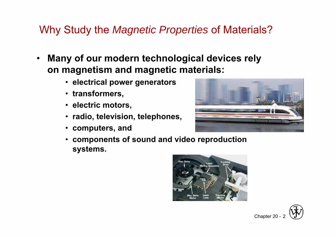
Why Study the Magnetic Properties of Materials?
• Many of our modern technological devices rely on magnetism and magnetic materials:
• electrical power generators• transformers, • electric motors, • radio, television, telephones, • computers, and • components of sound and video reproduction
systems.

Chapter 20 - 3
Magnetic Dipoles
Magnetic field lines of force around a current loop and a bar magnet.(Callister,2Ed.)
Magnetic dipolemoments are represented by arrows, as shown

Chapter 20 - 4
• Created by current through a coil:
• Relation for the applied magnetic field, H:
LINH
=
applied magnetic fieldunits = (ampere-turns/m)
current
Applied Magnetic Field
Applied magnetic field H
current I
N = total number of turnsL = length of each turn

Chapter 20 - 5
• Magnetic induction results in the material
• Magnetic susceptibility, χ (dimensionless)
Response to a Magnetic Field
current I
B = Magnetic Induction (tesla)inside the material
χ measures the material responserelative to a vacuum.
H
Bvacuum χ = 0
χ > 0
χ < 0

Chapter 20 - 6
• Measures the response of electrons to a magnetic field.
• Electrons produce magnetic moments:
• Net magnetic moment:--sum of moments from all electrons.
• Three types of response...
Magnetic Susceptibility,
Adapted from Fig. 20.4, Callister 7e.
magnetic moments
electron
nucleus
electron
spin
χ
Chapter 20 - 7
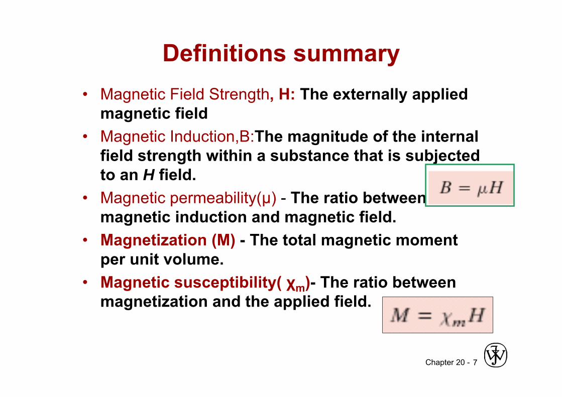
Definitions summary• Magnetic Field Strength, H: The externally applied
magnetic field• Magnetic Induction,B:The magnitude of the internal
field strength within a substance that is subjected to an H field.
• Magnetic permeability(µ) - The ratio between magnetic induction and magnetic field.
• Magnetization (M) - The total magnetic moment per unit volume.
• Magnetic susceptibility( χm)- The ratio between magnetization and the applied field.

Chapter 20 - 8
Magnetic Units and conversion factors

Chapter 20 - 9
Plot adapted from Fig. 20.6, Callister 7e. Values and materials from Table 20.2 and discussion in Section 20.4, Callister 7e.
Three Types of Magnetism
Magnetic induction B (tesla)
Strength of applied magnetic field (H) (ampere-turns/m)
vacuum (χ = 0)-5diamagnetic (χ ~ -10 )(1)
e.g., Al2O3, Cu, Au, Si, Ag, Zn
ferromagnetic e.g. Fe3O4, NiFe2O4ferrimagnetic e.g. ferrite(α), Co, Ni, Gd
(3)
(χ as large as 106 !)
(2) paramagnetice.g., Al, Cr, Mo, Na, Ti, Zr
(χ ~ 10-4)
permeability of a vacuum:(1.26 x 10⁻⁶ Henries/m)
HB oμχ+= )1(
Chapter 20 -10
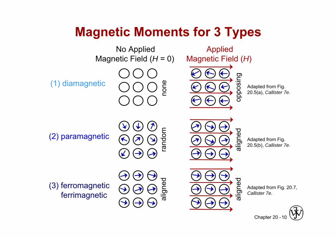
Magnetic Moments for 3 Types
Adapted from Fig. 20.5(a), Callister 7e.
No Applied Magnetic Field (H = 0)
Applied Magnetic Field (H)
(1) diamagnetic
none
oppo
sing
Adapted from Fig. 20.5(b), Callister 7e.
(2) paramagnetic
rand
om
alig
ned
Adapted from Fig. 20.7, Callister 7e.
(3) ferromagneticferrimagnetic al
igne
d
alig
ned

Chapter 20 -11
THE INFLUENCE OF TEMPERATURE ON MAGNETIC BEHAVIOR
Temperature can also influence the magnetic characteristics of materials. Raising the temperature of a solid results in an increase in the magnitude of the thermal vibrations of atoms .
The saturation magnetization is a maximum at 0 K, at which temperature the thermal vibrations are a minimum.
With increasing temperature, the saturation magnetization diminishes gradually and then abruptly drops to zero atwhat is called the Curie temperature Tc. Curie temperatures:
Chapter 20 -12
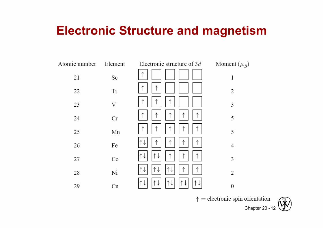
Electronic Structure and magnetism
Chapter 20 -13
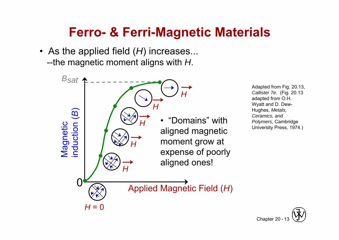
• As the applied field (H) increases...--the magnetic moment aligns with H.
Adapted from Fig. 20.13, Callister 7e. (Fig. 20.13 adapted from O.H. Wyatt and D. Dew-Hughes, Metals, Ceramics, and Polymers, Cambridge University Press, 1974.)
Ferro- & Ferri-Magnetic Materials
Applied Magnetic Field (H)
Mag
netic
in
duct
ion
(B)
0
Bsat
H = 0
H
H
H
HH
• “Domains” with aligned magnetic moment grow at expense of poorly aligned ones!

Chapter 20 -14
Adapted from Fig. 20.14, Callister 7e.
Permanent Magnets
Applied Magnetic Field (H)
1. initial (unmagnetized state)
B
large coercivity--good for perm magnets--add particles/voids to
make domain wallshard to move (e.g.,tungsten steel: Hc = 5900 amp-turn/m)
• Hard vs Soft Magnets
small coercivity--good for elec. motors(e.g., commercial iron 99.95 Fe)
Adapted from Fig. 20.19, Callister 7e. (Fig. 20.19 from K.M. Ralls, T.H. Courtney, and J. Wulff, Introduction to Materials Science and Engineering, John Wiley and Sons, Inc., 1976.)
Applied Magnetic Field (H)
B
Har
d
Sof
tHar
d
• Process: 2. apply H, cause alignment
4Negative H needed to demagnitize!
. Coercivity, HC
3. remove H, alignment stays! => permanent magnet!
Chapter 20 -15
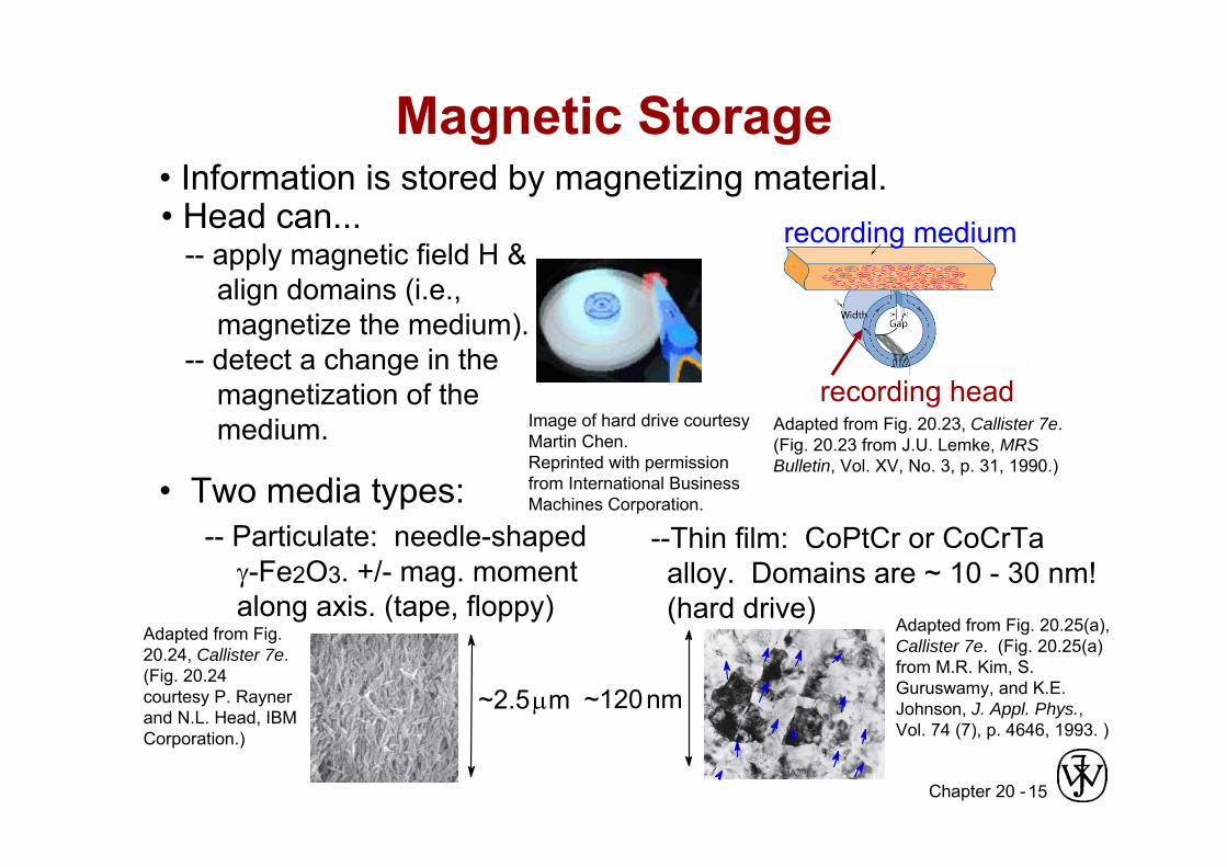
• Information is stored by magnetizing material.
Image of hard drive courtesy Martin Chen.Reprinted with permissionfrom International Business Machines Corporation.
• Head can...-- apply magnetic field H &
align domains (i.e.,magnetize the medium).
-- detect a change in themagnetization of themedium.
• Two media types:
recording head
recording medium
Adapted from Fig. 20.23, Callister 7e. (Fig. 20.23 from J.U. Lemke, MRS Bulletin, Vol. XV, No. 3, p. 31, 1990.)
Magnetic Storage
-- Particulate: needle-shapedγ-Fe2O3. +/- mag. moment along axis. (tape, floppy)
Adapted from Fig. 20.24, Callister 7e. (Fig. 20.24 courtesy P. Rayner and N.L. Head, IBM Corporation.)
~2.5μm
Adapted from Fig. 20.25(a), Callister 7e. (Fig. 20.25(a) from M.R. Kim, S. Guruswamy, and K.E. Johnson, J. Appl. Phys., Vol. 74 (7), p. 4646, 1993. )
~120nm
--Thin film: CoPtCr or CoCrTaalloy. Domains are ~ 10 - 30 nm!(hard drive)
Chapter 20 -16
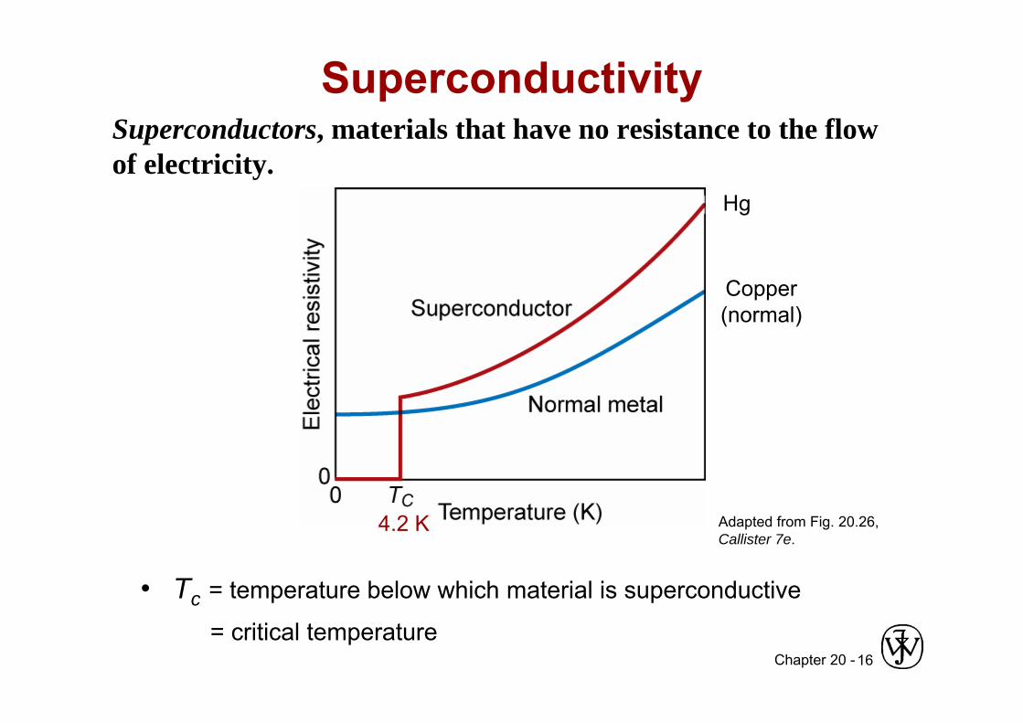
Superconductivity
• Tc = temperature below which material is superconductive
= critical temperature
Copper (normal)
Hg
4.2 K Adapted from Fig. 20.26, Callister 7e.
Superconductors, materials that have no resistance to the flow of electricity.
Chapter 20 -17
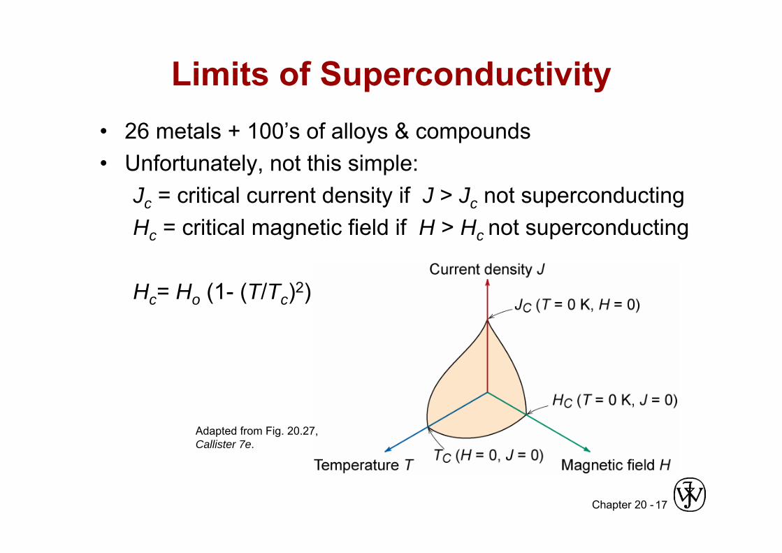
Limits of Superconductivity• 26 metals + 100’s of alloys & compounds• Unfortunately, not this simple:
Jc = critical current density if J > Jc not superconductingHc = critical magnetic field if H > Hc not superconducting
Hc= Ho (1- (T/Tc)2)
Adapted from Fig. 20.27, Callister 7e.
Chapter 20 -18
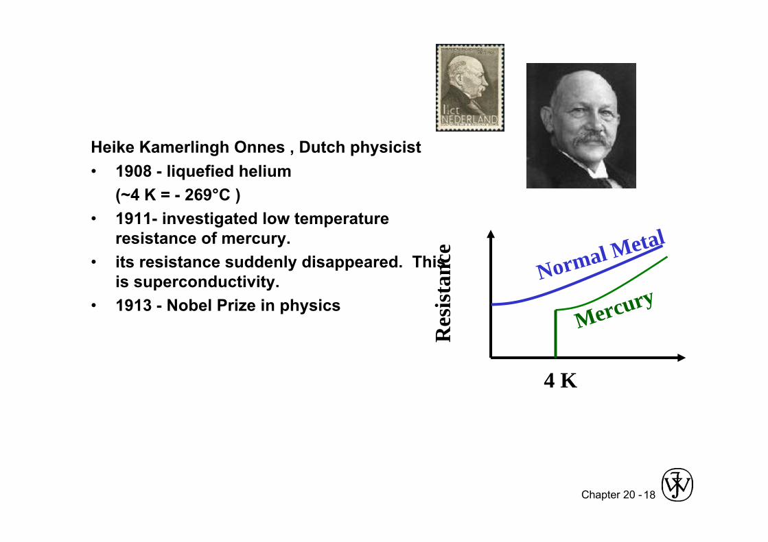
Heike Kamerlingh Onnes , Dutch physicist• 1908 - liquefied helium
(~4 K = - 269°C )• 1911- investigated low temperature
resistance of mercury.• its resistance suddenly disappeared. This
is superconductivity.• 1913 - Nobel Prize in physics
Discovery of Superconductivity
Res
ista
nce
Normal Metal
Mercury
4 K

Chapter 20 -19
History of Superconductivity
Bardeen, Cooper, Schrieffer Theory (1957)
Meissner Effect (1933)
High Temperature Superconductors (1985)
Müller & Bednorz

Chapter 20 -20
Superconducting Elements
Ambient Pressure
High Pressure

Chapter 20 -21
Kelvin Temperature Scale
0 K: All motion ceases
100oC = 373 K
0oC = 273 K
-145oC = 138 K“High” Temperature Superconductors
77 KAir (Nitrogen) liquifies
4 KHelium liquifies

Chapter 20 -22
Low Temperatures
Motion Ceases
0K
LiquidHelium
4K
LiquidNitrogen
77K
Room Temp300 K (27 0C)
“Regular”Superconductors 0 – 40 K
High TemperatureSuperconductors 0 – 138 K

Chapter 20 -23
DEMO 1
1. Two objects: a superconductor (the black brick) and a magnet. 2. Magneto-optical film is placed on the magnet to visualize its magnetic
properties. 3. The magnet is placed on the superconductor: no sign of levitation since
the superconductor is above the critical temperature. 4. Pouring liquid nitrogen which has a temperature of 77 Kelvins (-196
Celsius). The cooling takes a few minutes. 5. The magnet is placed above the superconductor: levitation! 6. The magnet returns back when pushed aside: the leviation is stable. 7. Simple check with a paper sheet: there is nothing but magnetic field
between the objects. 8. A close view. The magnet is rotating in the air without friction - the idea
used in flywheel applications for energy storage. 9. Moving the magnet around leads to a redistribution of magnetic field
inside the superconductor, which creates various stable positions and orientations for the levitating magnet.
10. The superconductor is taken out of the liquid nitrogen followed by its warming up above the critical temperature. The magnet is slowly landing: the levitation is over.

Chapter 20 -24
DEMO 2
1. The magnet is located on the superconductor: there is no interaction between them because the superconductor is above the critical temperature.
2. The magnet is placed on a glass plate so that its magnetic field penetrate the superconductor.
3. Pouring liquid nitrogen which has a temperature of 77 Kelvins (-196 Celsius). The cooling takes a few minutes.
4. The glass plate is removed but the magnet continues levitating above the superconductor.
5. The magnet is lifted up and the superconductor follows after it as if connected by invisible threads. These threads are magnetic field lines frozen-in in the superconductor and pinned there by microscopic inhomogeneities.
6. Repeating the same experiment. Sometimes the magnetic lines get disconnected, and the superconductor falls down. However the magnetic field remains trapped in the superconductor, and the lines re-connect again when the magnet approaches.
7. Levitation with slow rotation. Moving a paper sheet demonstrates that there is nothing but magnetic field between the objects.
8. The superconductor is taken out of the liquid nitrogen followed by its warming up above the critical temperature. The magnet is falling, the levitation is over.

Chapter 20 -25
Applications of Superconductors
• Devices that use the absence of resistance of superconductors
• High current superconducting wires.
• Radio Frequency filters in cell phone receivers
• New superconducting devices

Chapter 20 -26
Advances in Superconductivity• This research area was stagnant for many years.
– Everyone assumed Tc,max was about 23 K– Many theories said you couldn’t go higher
• 1987- new results published for Tc > 30 K– ceramics of form Ba1-x Kx BiO3-y
– Started enormous race. • Y Ba2Cu3O7-x Tc = 90 K• Tl2Ba2Ca2Cu3Ox Tc = 122 K• tricky to make since oxidation state is quite important
• Values now stabilized at ca. 120 K

Chapter 20 -27
Meissner Effect• Superconductors expel magnetic fields
• This is why a superconductor will float above a magnet
normal superconductorAdapted from Fig. 20.28, Callister 7e.

Chapter 20 -28
Current Flow in Superconductors
• Type I current only in outer skin- so amount of current limited
• Type II current flows within wire
M
H
Type I
Type II
complete diamagnetism mixed
state
HC1 HC2HC
normal

Chapter 20 -29
Superconducting Materials
Vacancies (X) provide electron coupling between CuO2 planes.
X
X
X
XX
XX
XBa BaY
YBa2Cu3O7
CuO2 planes
linear chains
CuO
Cu
(001) planes

Chapter 20 -30
Core Problem 20.1
• A coil of wire 0.25 m long and having 400 turns carries a current of 15 A.
a.) What is the magnitude of the magnetic field strength H?
b.) Compute the flux density B if the coil is in a vacuum?
c.) Compute the flux density inside a bar of chromium is found in Table 20.2.
d.) Compute the magnitude of magnetization M.

Chapter 20 -31
Solution• (a) We may calculate the magnetic field strength
generated by this coil using Equation 20.1 as
turns/m-A24000m 25.0
A) (15 (turns) 400
=
=
=l
NIH

Chapter 20 -32
(b) In a vacuum, the flux density is determined from Equation 20.3. Thus
tesla100168.3turns/m)-A 000 (24 H/m 10257.1
2
600
−
−
×=
×=
= HB μ
Chapter 20 -33
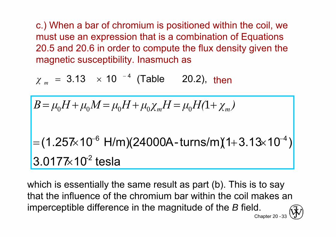
c.) When a bar of chromium is positioned within the coil, we must use an expression that is a combination of Equations 20.5 and 20.6 in order to compute the flux density given the magnetic susceptibility. Inasmuch as
20.2), (Table 103.13 4−×=mχ then
tesla 103.0177)103.13(1 turns/m)- A(24000 H/m) 10(1.257
2-
4 6
×
×+×=
+=+=+=
−−
)χH(μHχμHμMμHμB mm 100000
which is essentially the same result as part (b). This is to saythat the influence of the chromium bar within the coil makes an imperceptible difference in the magnitude of the B field.
Chapter 20 -34
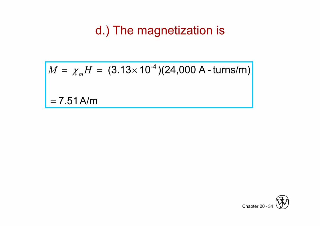
d.) The magnetization is
A/m7.51
turns/m)- A)(24,00010 (3.13 -4
=
×== H M mχ

Chapter 20 -35
Core Problem 20.5
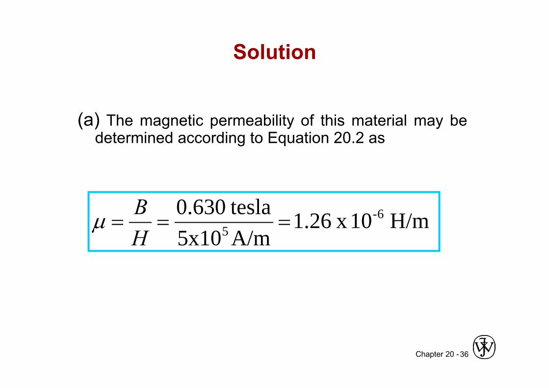
• The magnetic flux density within a bar of some material is 0.630 tesla at an H field of 5x 10⁵ A/m. Compute the following for this material
(a) the magnetic permeability and(b) the magnetic susceptibility.(c) What types of magnetism would you
suggest is (are) being displayed by this material? Why?
Chapter 20 -36
Solution
(a) The magnetic permeability of this material may be determined according to Equation 20.2 as
H/m10 x 1.26 A/m5x10
tesla0.630 6-5 ===
HBμ

Chapter 20 -37
(c) This material would display both diamagnetic and paramagnetic behavior. All materials are diamagnetic, and since is positive and on the order of 10-3, there would also be a paramagnetic contribution.
mχ
(b) The magnetic susceptibility is calculated using a combined form of Equations 20.4 and 20.7 as
3-6-
6-
10 x 2.39 1H/m1.257x10
H/m1.26x10=−=
== -µµ-µ χ rm 11
0

Chapter 20 -38
Core Problem 20.6
• The magnetization with in a bar of some metal alloy is 1.2x10⁶ A/m at an H field of 200 A/m. Compute the following
(a) the magnetic permeability and(b) the magnetic susceptibility.(c) The magnetic flux density wth in this
material(d) What types of magnetism would you
suggest as being displayed by this material? Why?

Chapter 20 -39
Solution(a) This portion of the problem calls for us to compute
the magnetic susceptibility within a bar of some metal alloy when M = 1.2 x 10⁶ A/m and H =200 A/m. This requires that we solve for χm from Equation 20.6
6000 A/m200
A/m1.2x10 HM 6
=== mχ
(b) In order to calculate the permeability we must employ acombined form of Equations 20.4 and 20.7 as follows
H/m10x 7.54 H/m)10 x 1)(1.257 (6000
3-
6-
=
+=
+== 1) ( 0m0r μχμμμ
Chapter 20 -40
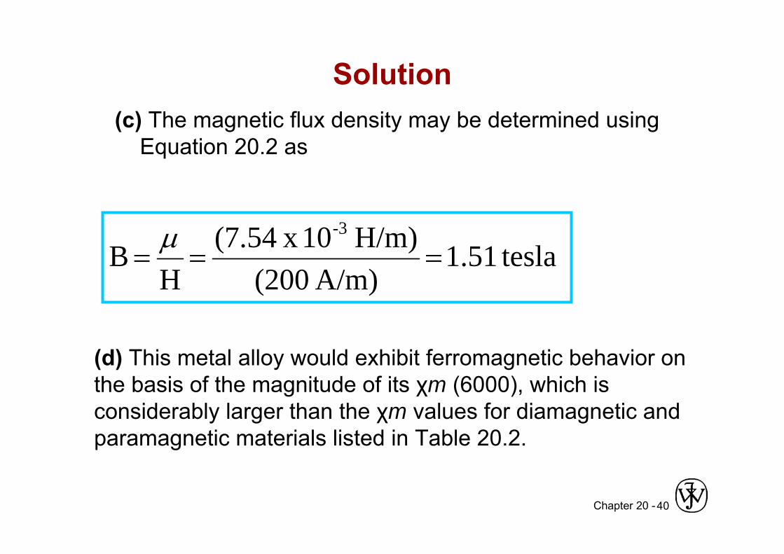
Solution(c) The magnetic flux density may be determined using
Equation 20.2 as
tesla1.51 A/m) (200
H/m)10 x (7.54 H
B -3
===μ
(d) This metal alloy would exhibit ferromagnetic behavior on the basis of the magnitude of its χm (6000), which is considerably larger than the χm values for diamagnetic and paramagnetic materials listed in Table 20.2.

Chapter 20 -41
Core Problem 20.21
• A bar of an iron-silicon alloy having B-H behaviour shown in Figure 20.29 is inserted within a coil of wire 0.40 m long and having 50 turns, through which passes a current of 0.1 A.
(a) What is the B field within this bar?(b) At this magnetic field,
(i) What is permeability?(ii) What is the permeabilty?(iii)What is susceptibility?(iv)What is magnetization?

Chapter 20 -42
• A magnetic field can be produced by:-- putting a current through a coil.
• Magnetic induction:-- occurs when a material is subjected to a magnetic field.-- is a change in magnetic moment from electrons.
• Types of material response to a field are:-- ferri- or ferro-magnetic (large magnetic induction)-- paramagnetic (poor magnetic induction)-- diamagnetic (opposing magnetic moment)
• Hard magnets: large coercivity.• Soft magnets: small coercivity.• Magnetic storage media:
-- particulate γ-Fe2O3 in polymeric film (tape or floppy)-- thin film CoPtCr or CoCrTa on glass disk (hard drive)
Summary
Chapter 20 -43
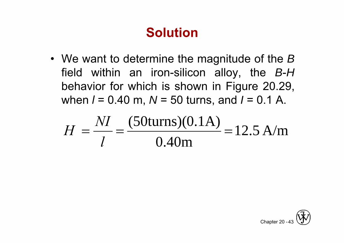
Solution
• We want to determine the magnitude of the B field within an iron-silicon alloy, the B-H behavior for which is shown in Figure 20.29, when l = 0.40 m, N = 50 turns, and I = 0.1 A.
A/m 12.5 0.40m
0.1A)(50turns)( ===l
NIH
Chapter 20 -44
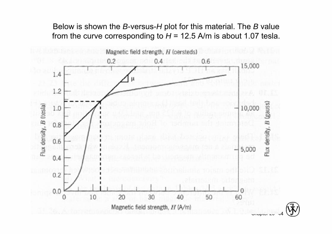
Below is shown the B-versus-H plot for this material. The B value from the curve corresponding to H = 12.5 A/m is about 1.07 tesla.

Chapter 20 -45
(i) The permeability at this field is just ΔB/ΔH of the tangent of the B-H curve at H = 12.5 A/m. The slope of this line as drawn in the above figure is
(ii) From Equation 20.4, the relative permeability is
H/m 10 x 3.36 0)A/m-(250.66)tesla-(1.50 2-==
ΔΔ
=HB µ
26,730 H/m1.257x10H/m3.36x10
6-
-2
0
===µµ µr

Chapter 20 -46
(iii) Using Equation 20.7, the susceptibility is
(iv) The magnetization is determined from Equation20.6 as
26,729 1 - 26,730 1-µ rm ===χ
A/m105x 3.34 A/m) 2.5(26,729)(1
=== H χM m

Chapter 20 -47
Core Problems: 20.1-20.5-20.6-20.21
Self-help Problems: Concept checks 20.1-20.3-
ANNOUNCEMENTSReading:An Iron-Silicon Alloy That is Used in Transformer Cores