ISSN 2277 Design and Development of Mini-BAJA Chassisijrrr.com/papers10-4/paper2-Design and...
5
7 Abstract - The objective is to design and develop safe and rigid roll cage for all terrain vehicle which accommodates all Baja SAE rulebook. The purpose of the roll cage is to provide a minimal three‐dimensional space surrounding the driver. The cage must be designed and fabricated to prevent any failure of the cages integrity. Before we started designing the roll cage, we had certain design parameters which we identified keeping in mind the application of the vehicle. The major parameters were High Ground clearance, Compact and light structure without compromising on the strength ergonomically and aesthetically sound Driver’s safety. The vehicle has to travel in adverse condition so; the worst case damages needs to be taken into consideration. We started the design process by first making our driver sit in his preferred driving posture, converted this into a 3D sketch and determined the position of the driver’s seat and the control pedals relative to each other. The position of driver was such that comfortable position is achieved considering 4 hours tough and dynamically versatile Endurance Race. The 3D modeling is done using creo software and analysis is done in hyperworks. As the results got in analysis, the changes have been made so as the factor of safety of the impact analysis of chassis is fulfilled. Keywords - ATV, Mini-Baja, Hyperworks I. INTRODUCTION The Main objective of the design was to build a sporty robust vehicle without compromising much on the performance in extreme terrains. Primary objective was that the vehicle should complete all the dynamic events without any breakdown. A core team was identified which overlooked, supervised and coordinated the different sub-teams responsible for design of identified major subsystems which was then integrated into a final design. The Main objective of the design was to build a sporty robust vehicle without compromising much on the performance in extreme terrains. Primary objective was that the vehicle should complete all the dynamic events without any breakdown. A core team was identified which overlooked, supervised and coordinated the different sub-teams responsible for design of identified major subsystems which was then integrated into a final design. Since the entire roll cage has been designed around our driver’s driving posture ergonomics has been given topmost priority. The steering wheel and pedals have been placed so that hand movement during is minimal. All foot pedals have been placed body roll ergonomically so that their operations are convenient over long period of time [1]. II. MATERIAL AND TUBE SIZE SELECTION Design considerations aside, the driving factor behind chassis material selection were the SAE competition vehicle regulations. Section 31.5 of the official 2016 Baja SAE Rule Book states that “the material used for the entire required roll cage members specified in 31.2.1 must, at minimum, be either circular steel tubing with an outside diameter of 2.5 cm (1 inch) and a wall thickness of 3.05 mm (.120 inch) and a carbon content of at least 0.18% OR steel members with at least equal bending stiffness and bending strength to 1018 steel having a circular cross section with a 2.54 cm (1 inch) outer diameter and a wall thickness of 3.05 mm (.120 inch). This ruling left the team with two options that were to either manufacture the roll cage from steel and the rest of the frame from aluminum or to make the entire chassis using steel. The slight increase in weight from an all steel chassis far outweighed the difficulty of reliably attaching a steel roll cage to an aluminum frame, thus the team chose to use steel. The steel chassis also has many other benefits including lower cost, higher safety factors, better manufacturability, and increased reliability. With this we have selected AISI 1018 Steel for our chassis. For primary members we have used 31.75 mm OD and 1.65 mm thick cross-sections and materials we have used is shown in following table with bending stiffness [1]. . Fig. 1. Mini- Baja chassis International Journal of Recent Research and Review, Vol. X, Issue 4, December 2017 ISSN 2277 – 8322 Design and Development of Mini-BAJA Chassis Tushar Digambar Tambe 1 M.Tech Research Scholar, VIT University, Chennai-India Email : [email protected] 1
Transcript of ISSN 2277 Design and Development of Mini-BAJA Chassisijrrr.com/papers10-4/paper2-Design and...

7
Abstract - The objective is to design and develop safe and
rigid roll cage for all terrain vehicle which accommodates
all Baja SAE rulebook. The purpose of the roll cage is to
provide a minimal three‐dimensional space surrounding
the driver. The cage must be designed and fabricated to
prevent any failure of the cages integrity. Before we
started designing the roll cage, we had certain design
parameters which we identified keeping in mind the
application of the vehicle. The major parameters were
High Ground clearance, Compact and light structure
without compromising on the strength ergonomically and
aesthetically sound Driver’s safety. The vehicle has to
travel in adverse condition so; the worst case damages
needs to be taken into consideration. We started the
design process by first making our driver sit in his
preferred driving posture, converted this into a 3D sketch
and determined the position of the driver’s seat and the
control pedals relative to each other. The position of
driver was such that comfortable position is achieved
considering 4 hours tough and dynamically versatile
Endurance Race. The 3D modeling is done using creo
software and analysis is done in hyperworks. As the
results got in analysis, the changes have been made so as
the factor of safety of the impact analysis of chassis is
fulfilled.
Keywords - ATV, Mini-Baja, Hyperworks
I. INTRODUCTION
The Main objective of the design was to build a sporty
robust vehicle without compromising much on the
performance in extreme terrains. Primary objective was
that the vehicle should complete all the dynamic events without any breakdown. A core team was identified
which overlooked, supervised and coordinated the
different sub-teams responsible for design of identified major subsystems which was then integrated into a final
design. The Main objective of the design was to build a
sporty robust vehicle without compromising much on the performance in extreme terrains. Primary objective
was that the vehicle should complete all the dynamic
events without any breakdown. A core team was
identified which overlooked, supervised and coordinated the different sub-teams responsible for
design of identified major subsystems which was then
integrated into a final design. Since the entire roll cage has been designed around our driver’s driving posture
ergonomics has been given topmost priority. The
steering wheel and pedals have been placed so that hand
movement during is minimal. All foot pedals have been placed body roll ergonomically so that their operations
are convenient over long period of time [1].
II. MATERIAL AND TUBE SIZE SELECTION
Design considerations aside, the driving factor behind
chassis material selection were the SAE competition
vehicle regulations. Section 31.5 of the official 2016 Baja SAE Rule Book states that “the material used for
the entire required roll cage members specified in
31.2.1 must, at minimum, be either circular steel tubing
with an outside diameter of 2.5 cm (1 inch) and a wall thickness of 3.05 mm (.120 inch) and a carbon content
of at least 0.18% OR steel members with at least equal
bending stiffness and bending strength to 1018 steel having a circular cross section with a 2.54 cm (1 inch)
outer diameter and a wall thickness of 3.05 mm (.120
inch). This ruling left the team with two options that
were to either manufacture the roll cage from steel and the rest of the frame from aluminum or to make the
entire chassis using steel. The slight increase in weight
from an all steel chassis far outweighed the difficulty of reliably attaching a steel roll cage to an aluminum
frame, thus the team chose to use steel. The steel chassis
also has many other benefits including lower cost, higher safety factors, better manufacturability, and
increased reliability. With this we have selected AISI
1018 Steel for our chassis. For primary members we
have used 31.75 mm OD and 1.65 mm thick cross-sections and materials we have used is shown in
following table with bending stiffness [1].
.
Fig. 1. Mini- Baja chassis
International Journal of Recent Research and Review, Vol. X, Issue 4, December 2017
ISSN 2277 – 8322
Design and Development of Mini-BAJA Chassis Tushar Digambar Tambe1
M.Tech Research Scholar, VIT University, Chennai-India
Email : [email protected]

8
In order to optimize the tubular structure, specific tubes
or areas were focused on during each FEA simulation. The SAE rule book and driver envelope specifications
(ergonomics) dictated the placement of many of the
main structural tubes, so the bulk of refinement
occurred with tube size, wall thickness, and location of bracing members. During each analysis, the areas of
high stress were concentrated on and alleviated by
adding bracing members to tune the stiffness and re-distribute load to other areas. Additionally, the tube
size and wall thicknesses were adjusted until they were
all uniformly stressed. This was a difficult process
because as the chassis was optimized for one loading scenario, the changes made affected the stress
distributions in the other load cases [2-3].
Table I Equivalency Calculations
We have done the Torsional Analysis in order to obtain
desired torsional rigidity and the gusseting members are
placed according to it.
Fig. 2. Chassis after Torsional analysis
Table II Torsional Analysis
Total deformation in Y-direction = Δy1= 2.56mm.
Total deformation in -Y-direction = Δy2= 2.56mm. We calculated torsional rigidity of the chassis by using
following formula,
Torsional Rigidity = 𝑇
𝑡𝑎𝑛−1(Δy1+Δy2
2∗𝑙)
Where, l = distance between Centre of car and
suspension pickup points.
Torsional Rigidity = 1252.54
𝑡𝑎𝑛−1(0.00256+0.00256
2∗0.28)
Torsional Rigidity = 2391.256 N.m/degree
Fig. 3. Torsional Analysis
Fig. 4. Torsional Analysis
III. DYNAMIC ANALYSIS
A. Front impact analysis (Car to wall)
In order to simulate the frontal impact crash, the vehicle was assumed to impact upon a stationary rigid mass
with a speed of 50 Kmph [4].
WEIGHT (kg) Torsional Rigidity (Nm/deg) Colour
30.32 1619.19 31.16 1873.82 32.54 2158.48 34.12 2391.25

9
Fig. 5. Displacement
Fig. 6. Stress
Fig. 7. Energy Conversion Graph
The deformation obtained clearly shows the driver is
completely safe and the vehicle is safe.
B. Front impact analysis (Car to Car)
In order to simulate the frontal impact crash, the vehicle
was assumed to impact upon a stationary car with a
speed of 50 Kmph. The car is placed in front of moving
car and the results were checked.
Fig. 8. Displacement
Fig. 9(a) Stress
Fig. 9(b) Energy Conversion Graph
C. Rear impact analysis
Fig. 10. Displacement

10
Fig. 11. Stress
Fig. 12. Energy Conversion Graph
All results clearly show the chassis is very safe in
impact load conditions.
D. Side impact
In order to simulate the side impact crash, it was
assumed that vehicle running at speed of 40kmph
makes an impact on one of the side of the roll cage.
Fig. 13. Displacement
Fig. 14. Stress
Fig. 15. Energy Conversion Graph
The amount of impact at worst case scenarios in
dynamics analysis shows the rigidity of the chassis.
E. Bending moment analysis
Bending stiffness of roll cage is calculated by using
formula,
K= 𝑊
𝑑
Where, K = Bending stiffness of roll cage
W = Applied force
d = Displacement
Fig. 16. Boundary Conditions
11
Fig. 17. Displacement
Fig. 18. Stress
K= 𝑊
𝑑
=6867
2.455
K = 2797.14 N/mm
Bending Stiffness = 2797.14 N/mm
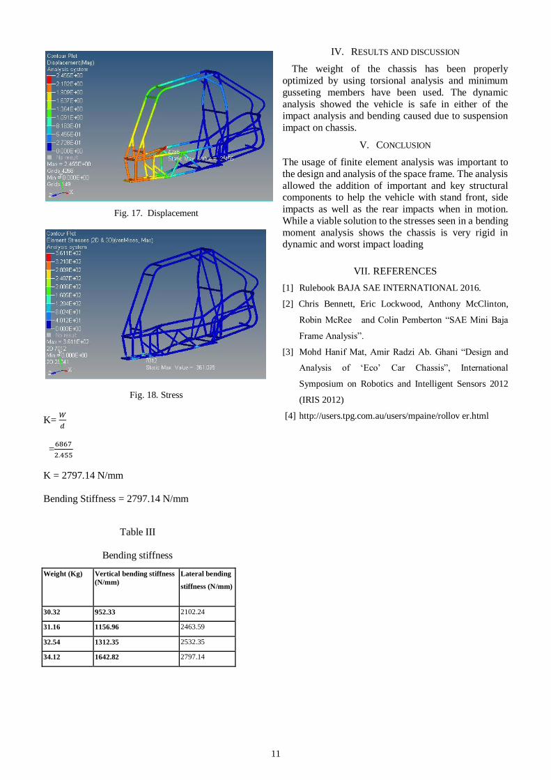
Table III
Bending stiffness
IV. RESULTS AND DISCUSSION
The weight of the chassis has been properly
optimized by using torsional analysis and minimum
gusseting members have been used. The dynamic
analysis showed the vehicle is safe in either of the impact analysis and bending caused due to suspension
impact on chassis.
V. CONCLUSION
The usage of finite element analysis was important to
the design and analysis of the space frame. The analysis
allowed the addition of important and key structural components to help the vehicle with stand front, side
impacts as well as the rear impacts when in motion.
While a viable solution to the stresses seen in a bending
moment analysis shows the chassis is very rigid in dynamic and worst impact loading
VII. REFERENCES
[1] Rulebook BAJA SAE INTERNATIONAL 2016.
[2] Chris Bennett, Eric Lockwood, Anthony McClinton,
Robin McRee and Colin Pemberton “SAE Mini Baja
Frame Analysis”.
[3] Mohd Hanif Mat, Amir Radzi Ab. Ghani “Design and
Analysis of ‘Eco’ Car Chassis”, International
Symposium on Robotics and Intelligent Sensors 2012
(IRIS 2012)
[4] http://users.tpg.com.au/users/mpaine/rollov er.html
Weight (Kg) Vertical bending stiffness
(N/mm)
Lateral bending
stiffness (N/mm)
30.32 952.33 2102.24
31.16 1156.96 2463.59
32.54 1312.35 2532.35
34.12 1642.82 2797.14