ISSN 0007-084X Space Chronicle - BIS-Italia · Space Chronicle ISSN 0007-084X General Issue...
40
Space Chronicle ISSN 0007-084X General Issue Publication Date: 19 November 2013 JBIS Journal of the British Interplanetary Society Vol. 66, Suppl. 2, 2013
-
Upload
truongcong -
Category
Documents
-
view
244 -
download
0
Transcript of ISSN 0007-084X Space Chronicle - BIS-Italia · Space Chronicle ISSN 0007-084X General Issue...

Space ChronicleISSN 0007-084X
General Issue
Publication Date: 19 November 2013JBIS Journal of the British
Interplanetary Society Vol. 66, Suppl. 2, 2013

Space Chronicle: JBIS Supplement
Editor: John Becklake
Production Assistant: B. Jones
Promotion: S. Parry
Space Chronicle Office: 27/29 South Lambeth Road, London, SW8 1SZ, England.
Tel: 020 7735 3160Fax: 020 7587 5118Email: [email protected]
* * *
Space Chronicle is a publication which promotes the objectives of the British Interplanetary Society. Opinions expressed in signed articles are those of the contributors and do not necessarily reflect the views of the Editor or the Council of the British Interplanetary Society. Security clearance, where necessary, is the responsibility of the author.
* * *
Space Chronicle is distributed worldwide by mail and may be received by annual subscription or purchase of single copies. It is available through membership of the British Interplanetary Society at much reduced rates.
* * *
Published by the British Interplanetary Society, 27/29 South Lambeth Road, London, SW8 1SZ, England. Registered Company No: 402498. Registered Charity No: 250556. Printed by Latimer Trend & Company Ltd, Estover Road, Plymouth, PL6 7PY, England.
* * *
Copyright © British Interplanetary Society 2013. No part of this magazine may be reproduced or transmitted in any form or by any means, electronic or mechanical, including photocopying or recording by any information storage or retrieval system without prior permission from the Publishers.
Space Chronicle welcomes the submission for publication of technical articles of general interest, historical contributions and reviews in space science and technology, astronautics
and related fields.
Text should be:
1. As concise as the content allows;
2. Submitted in both electronic form(*) and hardcopy;
* Text can be accepted in Word for Windows up to Version Word 2007.
Illustrations should be either:
1. Photographic prints, line drawings or 35 mm slides. (Not transparencies); or
2. High resolution (Photos - 300 dpi and Line drawings - 600 dpi) electronic images on disk/email in either jpg or tiff format.
More detailed information and a License to Publish can be obtained from www.bis-space.com/publications or by contacting the Space Chronicle office.
Material for publication including a signed License to Publish should be sent to:
Space Chronicle The British Interplanetary Society 27/29 South Lambeth Road London SW8 1SZ UK
or via email to [email protected]
Authors will receive a complimentary copy of the issue in which their paper appears.
Space Chronicle issues are published as a part of JBIS, but as Supplements to preserve the continuity of the regular series of JBIS (blue cover) issues.
The July/August 2013 issue of the Journal of the British Interplanetary Society is now available and contains the following papers:
Review, Analyses, and Recommendations Related to Modern International use of Nuclear Space Technologies with Focus on United States and RussiaScience Fiction and the Big QuestionsInterstellar Flight, Imagination and Myth Creation as an Effective Means for Enduring InspirationInterstellar Colonization and Multi-Generation Spaceships: Getting There is Half the FunUtilizing Video GamesThe Interstellar Vision: Principles and PracticeComparison of Historic Exploration with Contemporary Space Policy Suggests a Retheorisation of SettingsWarp Field Mechanics 101Project Icarus: A Review of the Daedalus Main Propulsion SystemEvolutionary Lightsailing Missions for the 100-Year Starship
Copies of JBIS, priced at £15 for members, £40 to non-members, P&P: UK £1.50, Europe £3.50, Rest of the World £3.50
Back issues are also available and can be obtained from The British Interplanetary Society, 27/29 South Lambeth Road, London, SW8 1SZ, England
JBIS Journal of the BritishInterplanetary Society

45
46 Mystery WW2 German Liquid Rocket Engine Martin Postranecky
49 Walterwerke KG Shamus Reddin
65 The Nuclear Possibility: History, Current Status and Future Prospects Anders Hansson
77 The Ariane 5 from a Technical Point of View: The Ariane 5 ECA Versus its Early 5G Version Lieven Roesems
* * *
LIST OF CONTENTS
JBIS
Published By The British Interplanetary Society
Space ChronicleJournal of the BritishInterplanetary Society Vol. 66, Suppl. 2, 2013
Front Cover: (upper left) Artist’s concept of the Jupiter Icy Moons Orbiter (JIMO). (lower left) Walter U-Boat V80 on trial in the Schlei inlet. (right) Cut open view of an Ariane 5G. The payload pictured is that of Ariane 502, launched on 30 October 1997. The payload was stacked using a SPELTRA payload adapter.

46
Martin PostraneckySpace Chronicle: JBIS, Vol. 66, pp.46-48, 2013
In the eastern corner of Moravia in the Czech Republic, near the border with Slovakia, there is a little known private military museum based in the former Czechoslovak Army Base Sokolov outside the town Slavicin. This “Army Park Slavicin” [1], founded in 2006, aims to build up a museum of military vehicles, arms and equipment of the former Czechoslovak People’s Army.
It also includes collections (unfortunately incomplete) of various products of nearby munitions factories during and after the Second World War
The museum contains an unique collection of military rockets and missiles, including vehicles and launchers, mainly of Soviet and Czech manufacture from the 1960’s onwards. Also included are various training aids, sectioned rocket motors, etc [2].
Among this cornucopia of modern military rocketry there stands an obviously old, sad, strange, sectioned rocket motor with an inconspicuous, hand-written note stuck on with sellotape, which just says - in Czech - “Nemecka Pokusna PL Raketa” (“German Test AA Rocket” in English) [3].
When we visited this museum in the spring of 2013 (and you may need to make a prior appointment by telephone or email, as this place is normally open to public only on Sundays during the summer months - apart from special events), the guide had no idea what this engine was, and where it came from. He said that, as far as he knew, it was donated to the collection by somebody who “worked in the military/explosives industry” and didn’t wish to see it “thrown on the scrap heap after his retirement...”
Our question is - what engine is it, and how it came to be there?
There doesn’t appear to be much to go on to try and identify this rocket motor (Fig. 1). It is obviously a small (Fig. 2), ~2ft/60cm tall, liquid-bi-fuel rocket engine, with double-walled chamber construction for cooling, and with multiple (oxidiser?) injectors in four staggered rows (Fig. 3), one central-threaded (fuel?) injector bushing (no injector present), and an almost cylindrical chamber - very unlike the usual spherical A-4 shape chamber.
There were not many German liquid-bi-fuel anti-aircraft rockets made during the WW2, and the size is the limiting factor.
It looks almost as a small-scale version of the EMW Wasserfall engine [4], but not as spherical.
Mystery WW2 German Liquid Rocket Engine
MARTIN POSTRANECKY, FBISEmail: [email protected]
Fig. 1 Test AA Rocket Engine. (Martin Postranecky)
A quick search through some old reference material, and discussions with friends and colleagues, produced few possible answers: from the size and shape it could be the VfK Zg.613-A/-A01 engine, as designed for the Rheinmetall-Borsig Rheintochter R3(F) anti-aircraft rocket - this engine was also used for tests of the experimental Messerschmitt Enzian E-3, E-4 and E-5 test articles [5, 6].
It was designed by Dr. Helmuth Konrad (Conrad?) of the Berlin Technische Hochschule, working for the “Deutsche Versuchsanstalt fur Kraftfahrzeuge und Fahrzeuge Motoren” (DVK), in 1944 and built and flown in 1945 [5, 6, 7].
It used Salbei (92% HNO3 + 8% H2SO4) as oxidiser and Visol (Vinyl Isobutyl Ether) as fuel, pressurised by compressed air. There is a Rheintochter R3 engine at RAF Cosford Museum [8, 9] which, if accessible, will be examined for comparison.

47
Mystery WW2 German Liquid Rocket Engine
Fig. 2 Some of the SAM rocket engines displayed at the Army Park Slavicin. From left; engine of S-200 ‘Vega’ Soviet large SAM missile, the unknown mystery German liquid engine, a sectioned engine from S-75 ‘Volchov’ SAM missile and a nozzle from a solid booster of the S-200 ‘Vega’. (Mgr. Jirka Kroulik)

48
Martin Postranecky
References
* * *
Few other options mentioned were the experimental Dr. Konrad DVK SG20 engine for the Rheinmetall-Borsig Feuerlilie F55 tests [10] - probably too small, or the Walter HWK 109-739 original engine for Enzian [11] - the wrong shape, or the BMW 109-558 engine for the Henschel Hs-117 Schmetterling rocket [12] - too small & the wrong shape.
A completely different suggestion was made by my Czech friend Mgr. Jirka Kroulik, based on his reading of the very well researched paper by Olaf H. Przybilski from Dresden University [13]. In this paper it is shown that during the period 1936 - 1945, intense research projects were conducted at various German
universities, aimed at designing improved injectors and mixers for large A-4 type liquid-fuel rocket engines, with articles being tested at Kummersdorf and Peenemunde. Could this be one of these test engines? But without detailed research in German archives, this would be impossible to prove. Also, the paper label does seem to point to an AA rocket.
So, let us say that it could well be the Konrad VfK Zg.613-A engine - unless somebody can show us a better fit!
And, finally, how did this (sectioned) engine came to be in this remote Moravian museum?
It is known that a manufacture of the A-4/V-2 engines was being prepared in the (pro-German) Slovakian armament factory in Dubnice nad Vahem (then part of “Hermann Goring Waffenwerke A.G.”) in 1945 [14]. Is it just possible that there were plans to manufacture other rocket parts there...?
But the most likely explanation is that this engine found its way, after the war - possibly via the Soviet Union - to some military or technical research establishment in the Czechoslovak Republic where it was used for research or teaching purposes.
But we will probably never know - unless somebody reading this can come up with the definitive answer?
Fig. 3 Enlargement of (oxidiser?) injectors. Note the difference between rows 1, 2, 3 and 4. (Martin Postranecky)
1. “Vojenske muzeum Armypark Slavicin” (in Czech), http://armypark.slavicin.org/armypark/armypark. (Last Accessed 4 November 2013)
2. “Army Park Slavicin”, https://www.facebook.com/pages/Army-Park-Slavi%C4%8D%C3%ADn/188546891158567. (Last Accessed 4 November 2013)
3. View of the rocket engines display, https://sphotos-a-lhr.xx.fbcdn.net/hphotos-ash4/305574_616557371690848_763369076_n.jpg. (Last Accessed 4 November 2013)
4. “General Survey of Rocket Motor Development in Germany”, 93 pages original US NAVY report by Lowell Lawrence, November 1945, http://www.cdvandt.org/Wunderwaffen-file-11110.pdf, pages 49, 50. (Last Accessed 4 November 2013)
5. “General Survey of Rocket Motor Development in Germany”, http://www.cdvandt.org/Wunderwaffen-file-11110.pdf, pages 53, 54, 55. (Last Accessed 4 November 2013)
6. Theodor Benecke et al., “Flugkorper und Lenkraketen: Die Entwicklungsgeschichte der deutschen gelenkten Flugkorper vom Beginn dieses Jahrhunderts bis heute”, Bernard & Graefe, Koblenz, 1987, pages 49, 148-149.
7. “General Survey of Rocket Motor Development in Germany”, http://www.cdvandt.org/Wunderwaffen-file-11110.pdf, page 9.
(Last Accessed 4 November 2013)8. John Christopher, “The Race for Hitler’s X-Planes: Britain’s 1945
Mission To Capture Secret Luftwaffe Technology”, The History Press Ltd, London, 2012, page 135.
9. RAF Museum Cosford 2012: Rheintochter R3 rocket engine photographs, http://eliasson.smugmug.com/Airplanes/Museums/RAF-Museum-Cosford-2012/i-M65LXVd; More photos of the Rheintochter R3 rocket engine at Cosford, http://forum.valka.cz/files/r3_1_212.jpg, http://forum.valka.cz/files/r3_775.jpg. (Last Accessed 4 November 2013)
10. Feuerlilie F55 details, http://www.luft46.com/missile/rheinf55.html. (Last Accessed 4 November 2013)
11. “The HWK 109-739 Motor: Bi-fuel rocket motor for the Enzian missile”, http://www.walterwerke.co.uk/missiles/109739.htm. (Last Accessed 4 November 2013)
12. “The BMW 109-558 Motor: Bi-fuel rocket motor for Hs.117 missile”, http://www.walterwerke.co.uk/missiles/109558.htm. (Last Accessed 4 November 2013)
13. O.H. Przybilski, “The Germans and the Development of Rocket Engines in the USSR”, JBIS, 55, pp.404-427, 2002.
14. Mgr. Jirka Kroulik, Prague, Czech Republic, private communication.
49
Walterwerke KGSpace Chronicle: JBIS, Vol. 66, pp.49-64, 2013
Walterwerke KG
SHAMUS REDDIN
Biography and History
A largely colourless liquid, hydrogen peroxide has a heat energy, pound for pound, equivalent to gunpowder. Decomposed in the presence of a catalyst, high strength hydrogen peroxide produces superheated steam and oxygen at a temperature of 500 degrees centigrade. In use, it was known variously as “Ingolin” and “Aurol” in the German Kriegsmarine (Navy) and “T-Stoff” in the Luftwaffe (Air Force) and Wehrmacht (Army).
Hellmuth Walter was born on 26 August 1900. In many respects he was a traditional German family man, who married aged 35 the 26 year old Ingeborg Möller during the period when his business was rapidly expanding. Together they went on to have five children. From an early age Walter had shown an interest in mechanical objects. Eschewing his father’s painting business, Walter left secondary school early for an apprenticeship as a mechanical engineer at a shipyard in Hamburg. Here he gained experience with all types of marine motors from piston steam engines to diesel and steam turbines. It became clear that without a solid theoretical base Walter’s ambition to become a professional engineer would be difficult to realise, so he resumed his formal education by enrolling at the Hamburg Technical Institute to study mechanical engineering. Directly after graduating he was taken on at the Stettiner Maschinenbau AG Vulcan shipyard in Hamburg in 1923.
Walter had been a keen and intelligent student and with the experience from his apprentice days, he began working under Dr Bauer, then well-known in the field of marine turbines. Within two years Walter was granted his first turbine process patent. The next year, following a secondment to Berlin to the Army Ordnance Office to work on an anti-aircraft command unit, Walter took the opportunity of being in the capital to promote his gas turbine work around the Naval Command [1].
Hellmuth Walter was a German engineer and what we might now regard as a business entrepreneur. He developed an idea for a marine turbine propulsion system to operate independently of atmospheric air using high strength hydrogen peroxide. During the development of this system it became clear to him that the energy output of a controlled decomposition of hydrogen peroxide could find applications in a range of motive systems below the sea, in the air and on land. The factory which he founded became part manufacturer and part development institute for his ideas, and during the Second World War designed a number of hydrogen peroxide motors for advanced weapons systems. Allied Intelligence was aware of Walter’s work and the factory at Kiel became a key investigation and exploitation target. Upon capture, the range and diversity of applications which had been developed at Walterwerke proved staggering. The subsequent exploitation of German research was part of British scientific development of the late 1940s, from the direct employment of Walter personnel to the actual use of captured hardware.
In 1930 his lobbying proved fruitful and with official approval for development, Walter moved to the Germaniawerft shipyard of Friedrich Krupp in Kiel to pursue his designs for a 2,000 hp gas turbine with rotary compressor for the German Navy.
Walter had for some time been musing on designs for a pet project of his, a high speed submarine. The problem was the unsuitability of internal combustion motors for realising the power potential in submarine diesel fuel during underwater travel. Walter could see that the combustion of diesel with an oxygen-carrying material would be independent of atmospheric air and, used in a modified design of his rotary compressor turbine, would fulfil his propulsion requirements for high-speed underwater travel. The idea for using hydrogen peroxide as a suitable oxygen carrier (the catalysed decomposition of hydrogen peroxide produces an oxygen-rich gas) evolved from discussions over a glass of beer with Rowehl a friend of his who had been the pilot of a torpedo-carrying aircraft during the Great War.
The Naval turbine project was not adopted, but the positive result for Walter was that the successful tests and improved efficiency of his designs gave him both the confidence to pursue his submarine ideas and a degree of influence in the German Navy. Walter therefore formed his own company, Hellmuth Walter Kommanditgesellschaft (known as Walterwerke for short, or HWK) in 1934 (initially working from a drawing office at home) to further research and develop his ideas [2].
In the 1930s the Munich Electrochemische Werke chemical company, Director Dr Albert Pietsch, was commercially producing 30% concentrations of hydrogen peroxide. Experiments had shown the viability of manufacturing greater concentrations, whilst at the same time the feasibility of their
50
Shamus Reddin
use had been improved by new types of stainless steel and polyvinyl chloride for resistant containers and gaskets. Walter wrote to Pietsch promoting the potential opportunities in making greater use of his product, whilst concurrently lobbying to stir an interest in high-speed underwater propulsion in the German Naval authorities. Pietsch was persuaded that Walter’s proposals could be commercially viable, and suggested a working strength of 80% as having a more useful power content, whilst still practical enough for safe handling [3].
Walter was able to use the testing work done at the Germania shipyard to demonstrate practical progress in his ideas and consequently Pietsch invested 400,000 Reich Marks (RM) in Walter’s company, with which the latter was able to purchase development facilities. Within twelve months Walter had attracted further investment from the German Naval High Command of 10 million RM for an experimental plant, and Walterwerke was established on the site of an old gasworks at Wik near Kiel. This was followed by a further 10 million RM development funding to build heavy engineering buildings, test sheds and propellant storage facilities [4].
Submarine Development
By 1936 Walter had a provisional 4,000 hp marine propulsion unit. The 80% hydrogen peroxide was catalysed in a decomposer by metal or porcelain rings coated with a layer of manganite and caustic potash. To the oxygen-rich decomposition steam, fuel oil was added in a combustion chamber and the expanding gases directed to a turbine producing propulsive thrust. Water was injected into the hot gases, cooling them to a temperature which would not damage the turbine.
Walter’s proposals were met with scepticism in official circles, but he was able to personally interest Admiral Karl Dönitz, who assisted in obtaining a contract for a prototype hydrogen peroxide submarine. Once funding was in place, Walter produced the 80 ton, 2,000 hp, V80. A four man submarine, V80 had a basic peroxide motor without fuel injection. It did, however, have a revolutionary high-speed shape, developed with the aid of a wind-tunnel. Construction began at the Germaniawerft in 1939, with launch of the V80 in April 1940. Tested in the waters of the Schlei, an inlet on the Baltic, eighty successful runs were made, with a maximum submerged speed achieved of 26 knots – compared with the 7.5 knots of the Type VII Atlantic U-Boat (which with diesel engines on the surface could only muster 17 knots).
Based on this progress, Walter was commissioned to build an improved boat, the V300. The original design had a displacement of 300 tons and 4,000 hp turbine giving an underwater speed of 25 knots, but the project remained under-developed after two years of work with Kriegsmarine involvement. Despite trials in 1943, he had already abandoned the V300 and moved on to projects over which he could exercise greater personal control.
Walter was of the opinion that U-Boat speed should be at least as high as that of a destroyer, preferably 50% greater than the attacked vessel. With the speed of convoys to be expected to be 16 knots, he argued that the U-Boat should be able to make at least 25 knots. Walter pressed Dönitz to let him continue naval development and the new project became the Type XVII U-Boat. Following a competitive process, Blohm and Voss proved to have built the superior version and a contract to
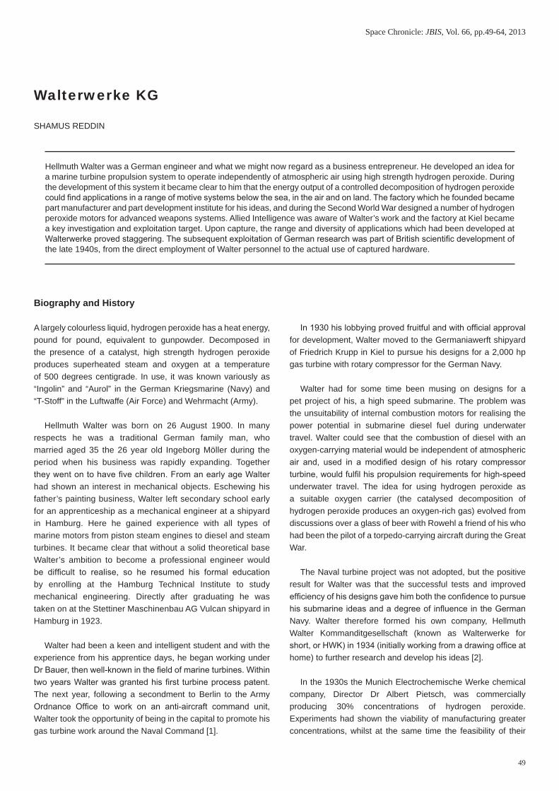
Hellmuth Walter (centre) in the canteen at Walterwerke in Kiel.(Courtesy The National Archives, Kew)

51
Walterwerke KG
produce twelve boats was agreed. Three of these Type XVIIB U-Boats had been delivered by April 1945 (U-1405, U-1406 and U-1407), each having a single 2,500 hp Walter turbine drive, with further hulls under construction; these were not complete when the war ended [5].
Walter continued research on U-Boat designs throughout the war; one did make it into production as the Type 21 - albeit with a battery-powered engine, instead of the peroxide drive – and a Type 26 was proposed with a 6,000 hp turbine, but the end of the war stopped development.
Aircraft Rocket Motors
Hellmuth Walter himself wrote [3] that once higher concentrations of hydrogen peroxide were available, possibilities for the power contained within the substance began to suggest themselves. It seemed a small step for the fundamental parts of the 1936 hydrogen peroxide marine plant (pumps, flow-regulator, decomposer and combustion chamber with cooling jacket) to be reformed as an airborne power plant.
Walter’s first rocket trials were conducted at Altenwalde, near Cuxhaven on the North Sea coast with the 80% solution of peroxide, by then being referred to by its code name of “T-Stoff”. A catalytic paste layer similar to that in the marine engine, was spread over perforated metal sheets in a decomposing chamber. T-Stoff was forced into the reaction vessel by compressed air, leading to a spontaneous decomposition. Having a reaction temperature of around 500o C. Walterwerke commonly referred to motors operating on this principle as “cold” motors. Experiments satisfied Walter engineers that thrusts of 1,000 kg could be obtained from a three litre reaction chamber, compact enough to be fitted in aircraft [2].
Aircraft Motor Development
The German Air Ministry’s Development Office created a special propulsion systems department in the existing Power Plant Group to oversee work on applying rocket motors to aircraft. Walterwerke’s first flight trials were conducted by pilots from the Deutsche Versuschsanstalt für Luftfahrt (DVL – German Laboratory for Aviation) in early 1937 at Ahlimbsmüle near Berlin, with an auxilliary Walter rocket unit fitted in Heinkel He.72 “Kadett”, D-EPAV. The pilot opened a cock in a compressed air line forcing peroxide into a reaction chamber containing catalytic paste. Constant maximum thrust of 100 kg could be maintained for 45 seconds. As confidence in the system grew, even Ernst Udet acted as pilot for one of the test flights [1]. The Heinkel He.72 installation was what might be called a technology demonstrator, and although valuable lessons were learned (the paste catalyst was rather unsatisfactory in performance), the system was not tested extensively for sustained flight [6].
To develop the principles further, a new motor design was installed in the rear fuselage of a Focke-Wulf Fw.56 “Stosser” D-JVYJ [1]. Although superficially similar to the rocket in the Heinkel He.72, the new unit used a liquid spray catalyst, (potassium permanganate, known by its codename as “Z-Stoff”), to replace the paste. The Z-Stoff was delivered by compressed air in a ratio of 1:20 with the peroxide. Tested in the Summer of 1937 at the DVL Neuhardenberg airfield, north-east of Berlin, thrust was not controllable in flight, but interchangeable reaction chambers, swapped before flight, gave a thrust range of 100 to 300 kg.
The Focke-Wulf Fw.56 D-JVYJ made ninety successful test flights, with the rocket used during take-off and in flight. Of the only two unsuccessful flights, one was due to cold-weather
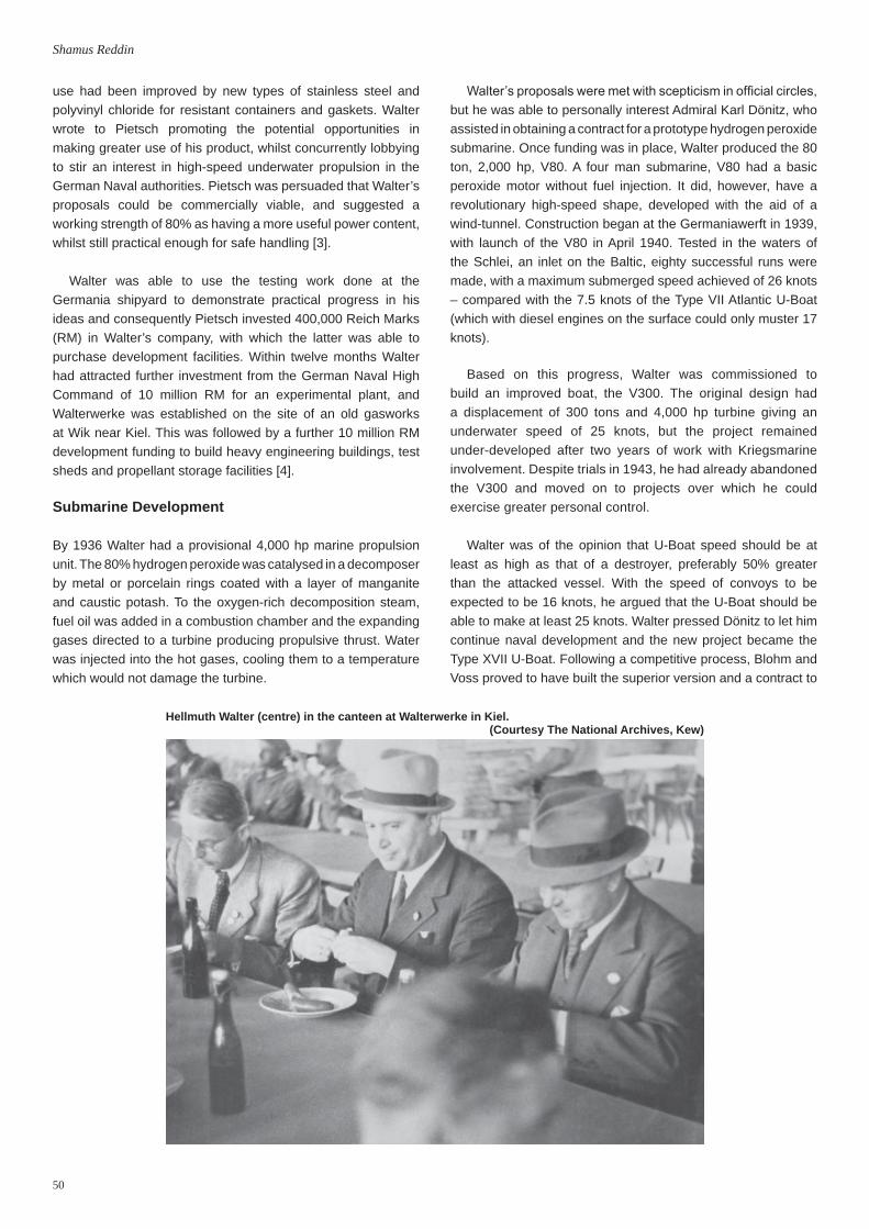
Walter U-Boat V80 on trial in the Schlei inlet. (Courtesy The National Archives, Kew)

52
Shamus Reddin
crystallisation of the liquid catalyst and the other to a mechanical fault in the pilot’s control lever. Much valuable flight experience was obtained, including the influence of the rocket on the rate of climb and longitudinal and lateral stability in climbing, level and banked flight [6].
The assisted take-off demonstrated on the Focke-Wulf Fw.56 was designed to generate interest within the Luftwaffe, and Walter was quickly able to re-engineer the main components with propellant tanks, into a self-contained unit. Carried externally with a parachute pack for recovery, Walterwerke allocated the unit, model RI-201, and it became an important design for them. These rocket “take-off packs” were successfully tested in the Summer of 1937 on a Dornier Do.18 and a Heinkel He.111 concurrently with the Focke-Wulf Fw.56 experiments and performance was found to be largely identical [7].
Adopted by the Luftwaffe and re-designated the HWK 109-500 for service use, the auxiliary take-off pack was one of the most important “cold” Walter power units, and was widely used throughout the war. Giving a thrust of 500 kg for 30 seconds, it could be manhandled onto aircraft by a small team, and after take-off recovered and re-used. Estimates suggest that approximately 3,000 operational flights were made, with no accidents directly attributable to the propellants [2].
Together with Walter’s rocket assisted flight experiments, a team under the design direction of Wernher Von Braun was developing a liquid oxygen aircraft rocket motor. In 1937 the German Air Ministry (RLM) ran competitive trials at Neuhardenberg of both the liquid oxygen and Walter peroxide systems fitted to Heinkel He.112. Initially successful in flight, a forced landing put the Von Braun aircraft out of action for a short time. Further development work was required and with
Von Braun’s principal focus being the large rocket system (subsequently to develop into the A4), liquid oxygen trials stalled. The Walter team however, were encouraged by their successes and continued flight experiments into the summer of 1937.
Walter had designed a new motor for the Heinkel He.112 which Walterwerke called the RI. It was a controlled thrust unit with a steam driven T-Stoff pump. The pump was driven by a steam turbine called the TP-1, which was provided by Klein, Schantzlin and Becker. It used steam derived from a pot into which T-Stoff and Z-Stoff were sprayed by compressed air. Although in this motor only the T-Stoff was pumped, (Z-Stoff was delivered by compressed air) the steam driven propellant pump was a particularly significant development for subsequent Walter motors.
After the initial tests in the fuselage of the Heinkel He.112 the system was modified with an automatic starting system for the turbine. The T-Stoff for this was taken off the main pump delivery [7]. By Autumn 1938 the Walter aircraft motor team had re-located to the new testing ground at Peenemünde. Of the further 28 flight tests, six were on the rocket motor alone [8].
Back in July 1937, project leader Walter Künzel in the Sonderentwicklung I at the Heinkel factory, Rostock-Marienehe, produced engineering drawings for a rocket-powered aircraft, the Heinkel He.176. In July 1938 the Heinkel He.176 was undergoing wind tunnel tests at Göttingen and given that the Walter team at Peenemünde already had a proven rocket system this was modified to fit the Heinkel airframe. By Autumn the Heinkel He.176 was undergoing roll tests at Peenemünde-West.
Focke Wulf Fw.56 with its Walter hydrogen peroxide rocket drive on test.(Courtesy The National Archives, Kew)

53
Walterwerke KG
Initially the rocket unit showed poor thrust regulation and it was not until April 1939 when modifications for pneumatic operation had been carried out, that stable thrust was achieved. Subsequently, on 20th June 1939 Erich Warsitz made the first full planned flight of the Heinkel He.176, the world’s first solely rocket-powered aircraft. The Heinkel He.176 made 19 flying tests at Peenemünde and Rechlin, including a demonstration in front of Hitler on 3rd July 1939. Although recognised as an historic airframe and preserved in a museum in Munich, the Heinkel He.176 was destroyed in an air-raid during the war [9].
Walter Production Units
The Reichsluft Ministerium (RLM - German Air Ministry) was amenable to suggestions of technology for weapons; anti-shipping operations with aerial torpedoes for example could be particularly hazardous for aircrew. Initial work on the Schwarz glider-bomb had shown potential, but its low speed made it vulnerable to interception. Henschel Flugzeugwerke AG had been commissioned to produce an improved anti-shipping missile but it was the arrival of Herbert Wagner in 1940 that energised the project. For Henschel, high-speed flight would improve target penetration and Walter was already operating a suitable rocket motor solution.
In a process they would go on to repeat, Walterwerke produced a modified version of their “cold” RI-201 take-off motor for the Henschel Hs.293 radio-controlled glider-bomb. The new RII-260, had propellants delivered by compressed air and developed a thrust of 600 kg for 10 seconds. The motor was initiated by a cartridge rupturing a diaphragm in the air pressure line and Z-Stoff catalyst was driven to the reaction chamber ahead of the T-Stoff. A flow reversal burner cup at the head of the reaction vessel
received T-Stoff injected directly. Thirty surrounding holes in the injector head produced a spray pattern meeting the reversed flow, assisting in the atomisation of the T-Stoff. The Z-Stoff was injected via a simple orifice, impinging on a flat plate to promote turbulence and mixing for reaction. Helical guide vanes in the reaction vessel increased the effective length of the combustion chamber, which terminated in a short expansion nozzle [10].
First flown in December 1940 with further test launchings in Spring and Summer of 1941, Walterwerke’s RII-260 was put into production as the HWK 109-507B principally by Heinkel at Jenbach. Operational use was worked up by test units at Peenemünde and finally, on 25th August 1943, twelve Dornier Do.217 of the operational squadron II/KG100 armed with Henschel Hs.293 weapons, approached ships of the Fifth Escort Group in the Bay of Biscay. HMS Landguard and HMS Bideford were the first targets of the new rocket-powered glider-bombs. Languard had a near-miss, and Bideford sustained slight damage to the superstructure as the Henschel Hs.293 passed through the rigging of her aerial mast. Two days later, HMS Egret was not so lucky and became the first ship sunk by a rocket-powered anti-ship weapon, with the loss of 222 hands [11].
The Henschel Hs.293 with its Walter motor continued operational use around the Mediterranean throughout 1943 and into 1944 and analysis of weapon remnants gave the Allies their first real indication of the level of technical ability of the Hellmuth Walter works. Tactically, the weapon was a modest success, but issues with target observation, radio control (given that the Allies devoted substantial resources to developing jamming systems) and Allied air superiority over targets led to only a small proportion (approx 20%) of launched missiles achieving target hits.
Heinkel He.176, the world’s first rocket plane, shown taking off.(Courtesy The National Archives, Kew)
54
Shamus Reddin
The Messesrschmitt Me.163 Rocket-Powered Fighter
Concurrently with other technology project designers, glider aerodynamicist Alexander Lippisch was seeking a power plant for his latest model, en route to a tailless interceptor aircraft. Walter’s most refined motor was the turbo-pumped version for the Heinkel He.176. In common with Walter’s other power units, that for the Lippisch DFS.194 was re-built specifically to fit within the airframe [8]. Undergoing flight tests at Peenemünde between October 1939 and November 1940, the DFS.194 was to evolve into the Messerschmitt Me.163 “Komet”, with Walter on-board as the designer of the power plants. Looking in more detail at the development of the power unit for the Messerschmitt Me.163 offers an interesting insight into Walterwerke’s rocket development processes.
For fitting within the initial model Messerschmitt Me.163A, Walter built a new motor, the RII-203. With a maximum thrust of 750 kg, it utilised T-Stoff/Z-Stoff in the ratio of approximately 750:100, the former being pumped, and the latter being driven by the T-Stoff pressure, with flow governed by a pressure balance. The decomposer was a long tubular shape, extending down the fuselage, positioning the main motor near to the front of the airframe to keep the centre of gravity within limits. Walter experiments on the DFS.194 had shown that in this shape, decomposition took place gradually, gas velocity increasing steadily, with only a negligible difference in efficiency compared to a conventional decomposer [2].
Initially Walterwerke received an order for six RII-203 motors, the first Messerschmitt Me.163A airframe delivered to Kiel in May 1941. By 18th July, RII-203 V1 (“V” - Versuchs-Geräte, “Test Unit”) was undergoing acceptance tests, liquid catalyst being used in the steam generator for driving the TP-10 fuel pump turbine. On the 13th August 1941 the first “sharp start” (rocket powered take-off) of an RII-203 powered Messerschmitt Me.163A was made. Flights continued at Peenemünde, but by October, results from unit V3 were showing that steam generation with liquid catalyst required such detailed and careful maintenance, that safe operation was proving barely possible. A new steam generator was designed, having solid, catalyst-impregnated stones, produced with the help of chemists at Peenmünde - although to operate properly it required a new formulation of T-Stoff with a different proportion of stabilizers. By December 1941, RII-203 V3 had completed acceptance tests at Kiel and test flying progressed. Results in June 1942 saw catalyst stones being received with variable quality; they frequently fractured during use leading to loss of catalytic action. As a remedy, Walterwerke doubled the capacity of the steam generator and retro-modified test RII-203 units in the same manner.
Development work continued, with Walterwerke modifying the TP-10 pump bearings against excessive T-Stoff leakage, and improving the propellant regulators to increase reliability and response at low thrust. However, flight results were showing
that the RII-203 motor would be unsuitable for use in a training aircraft. Poorly controlled Z-Stoff delivery caused irregular or oscillating thrust and explosive decompositions, which even the experienced test pilots found difficult to handle. Therefore, Walter engineers produced a modified unit, the RII-203B, for training units, with double propellant pump adding separate pressure circuits for T-Stoff and now Z-Stoff.
Interruption of propellant flow from the Messerschmitt Me.163A’s tanks during manouvering, caused excess T-Stoff in the decomposer, with loss of thrust, or the potential for explosive decomposition at the restoration of catalyst flow. By April, a safety cut-off system was undergoing bench testing, but it was not until January 1943 that RII-203 units V12-14 with the modifications were being delivered. Thus, the initial development phase of Walterwerke’s programme for a Messerschmitt Me.163 power unit had taken over two years [8].
For the heavier combat version of the Messerschmitt Me.163B, Walterwerke had planned a greater thrust “hot” motor (with a fuel burned in the oxygen-rich decomposition gases) and had begun development work in September 1940. Up to that point, their experiments with injecting gasoline into the decomposed T-Stoff gases had used powder or high-tension igniters to initiate combustion, and a continual flow of Z-Stoff to make sure decomposition continued. Pre-ignition explosions, restarting at stalled combustion, and the weight of their existing decomposer-combustion chamber combinations showed that hypergolic propellants mixed in a single reaction vessel should be the aim.
The use of hydrazine hydrate in combination with methanol as a hypergolic propellant was suggested by Lutz, Hofmann and Noeggerath as early as 1939. Walterwerke saw this as the basis of its Messerschmitt Me.163B hypergolic system, and expected to produce a simplified motor, the new “RII-209” which was to be based on modifications to the RII-203 unit. However, as difficulties with propellant regulation and the combustion chamber required further re-designs for the RII-203, Walter decided to dispense with the RII-209 and work up all the latest developments into a new motor, the RII-211, later given the RLM code HWK 109-509 [12].
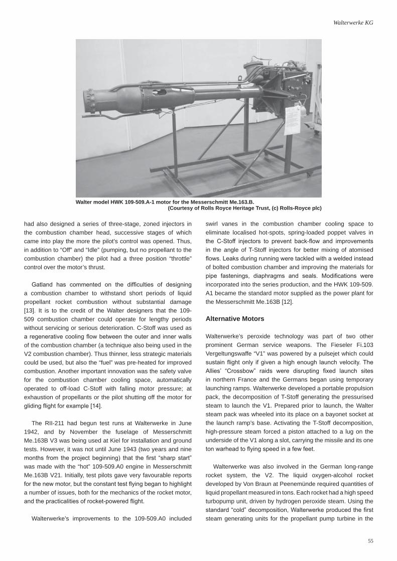
The HWK 109-509 became the main production motor of Walterwerke’s aircraft rockets. A 1,500 kg thrust, self-contained unit (built onto a frame, instead of into the fuselage), it had a number of innovative design features, principal among which was the “Regelgerät” combined pressure balance and propellant regulator. A “thrust” (or throttle) lever in the cockpit controlled T-Stoff flow to a solid catalyst decomposer which generated steam for a turbine-driven, dual-propellant pump. In the regulator, rising pump pressure of the C-Stoff “fuel” operated a set of split pushrods to control (but without the risk of direct contact) valves for the concomitant proportional flow of the T-Stoff. If for some reason C-Stoff pressure fell, T-Stoff flow to the combustion chamber was automatically reduced and the motor, even if it continued to run, was safe. Walterwerke
55
Walterwerke KG
had also designed a series of three-stage, zoned injectors in the combustion chamber head, successive stages of which came into play the more the pilot’s control was opened. Thus, in addition to “Off” and “Idle” (pumping, but no propellant to the combustion chamber) the pilot had a three position “throttle” control over the motor’s thrust.
Gatland has commented on the difficulties of designing a combustion chamber to withstand short periods of liquid propellant rocket combustion without substantial damage [13]. It is to the credit of the Walter designers that the 109-509 combustion chamber could operate for lengthy periods without servicing or serious deterioration. C-Stoff was used as a regenerative cooling flow between the outer and inner walls of the combustion chamber (a technique also being used in the V2 combustion chamber). Thus thinner, less strategic materials could be used, but also the “fuel” was pre-heated for improved combustion. Another important innovation was the safety valve for the combustion chamber cooling space, automatically operated to off-load C-Stoff with falling motor pressure; at exhaustion of propellants or the pilot shutting off the motor for gliding flight for example [14].
The RII-211 had begun test runs at Walterwerke in June 1942, and by November the fuselage of Messerschmitt Me.163B V3 was being used at Kiel for installation and ground tests. However, it was not until June 1943 (two years and nine months from the project beginning) that the first “sharp start” was made with the “hot” 109-509.A0 engine in Messerschmitt Me.163B V21. Initially, test pilots gave very favourable reports for the new motor, but the constant test flying began to highlight a number of issues, both for the mechanics of the rocket motor, and the practicalities of rocket-powered flight.
Walterwerke’s improvements to the 109-509.A0 included
swirl vanes in the combustion chamber cooling space to eliminate localised hot-spots, spring-loaded poppet valves in the C-Stoff injectors to prevent back-flow and improvements in the angle of T-Stoff injectors for better mixing of atomised flows. Leaks during running were tackled with a welded instead of bolted combustion chamber and improving the materials for pipe fastenings, diaphragms and seals. Modifications were incorporated into the series production, and the HWK 109-509.A1 became the standard motor supplied as the power plant for the Messerschmitt Me.163B [12].
Alternative Motors
Walterwerke’s peroxide technology was part of two other prominent German service weapons. The Fieseler Fi.103 Vergeltungswaffe “V1” was powered by a pulsejet which could sustain flight only if given a high enough launch velocity. The Allies’ “Crossbow” raids were disrupting fixed launch sites in northern France and the Germans began using temporary launching ramps. Walterwerke developed a portable propulsion pack, the decomposition of T-Stoff generating the pressurised steam to launch the V1. Prepared prior to launch, the Walter steam pack was wheeled into its place on a bayonet socket at the launch ramp’s base. Activating the T-Stoff decomposition, high-pressure steam forced a piston attached to a lug on the underside of the V1 along a slot, carrying the missile and its one ton warhead to flying speed in a few feet.
Walterwerke was also involved in the German long-range rocket system, the V2. The liquid oxygen-alcohol rocket developed by Von Braun at Peenemünde required quantities of liquid propellant measured in tons. Each rocket had a high speed turbopump unit, driven by hydrogen peroxide steam. Using the standard “cold” decomposition, Walterwerke produced the first steam generating units for the propellant pump turbine in the
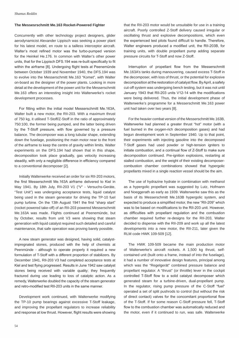
Walter model HWK 109-509.A-1 motor for the Messerschmitt Me.163.B.(Courtesy of Rolls Royce Heritage Trust, (c) Rolls-Royce plc)
56
Shamus Reddin
test missiles. Production V2 turbopumps were 580 hp units, the dual pumps moving 58 kg of alcohol and 72 kg of liquid oxygen every second [15].
Less known is that Walter had helped with the development of the aerodynamics of the V2. At Peenemünde the Von Braun team had been pursuing calculation tests on tail and control surface designs prior to the completion of their wind tunnel. However, even a wind tunnel could not replicate live flight testing, so Walterwerke supplied rocket models with the proportions and centre of gravity of the current Peenemünde-A5. Each model had a motor delivering T-Stoff onto a Z-Stoff paste, with a combustion time of 15 seconds.
“In March 1939 trials began [with the Walter rockets] at Peenemünde Bay and later on the Greifswald Oie. They gave a graphic picture of the different flying capacities of the models fitted with various tail surfaces” [16].
Walter Motor Developments
Walterwerke had been studying the pilot feedback on endurance issues with the Messerschmitt Me.163. A variable throat combustion chamber would have been ideal, but they were unable to develop this. Their solution was a smaller volume, higher pressure “cruising” combustion chamber, supplementary to the main thrust chamber. Walterwerke received a project order in October 1942 to develop a design they designated the HWK 109-509.B.
The basic 109-509 A motor with 100-1,500 kg thrust was supplemented with an auxilliary chamber of 300 kg thrust. A smaller capacity version of the flow and pressure balance regulator and a dual circuit T-Stoff control were added, together with throttle levers for main and auxiliary chambers. Initial coarse operation and high consumption led to an improved chamber with greater internal volume. Unlike the main combustion chamber, the auxilliary chamber had only one thrust stage, so the coolant C-Stoff was taken directly from the cooling space to the injectors [17].
Concurrently with researching the cruising chamber to improve endurance, Walterwerke was also tackling the problems of in-flight stalling and re-starting of the motor. The initial Messerschmitt Me.163 design was to have had a pressurised cabin, and for this an accessories unit with gearing from the turbo-pump was included on the original HWK 109-509 to which was attached a Bosch electrical starter motor. However, the pressure cabin was not included on the Messerschmitt Me.163B and Walterwerke’s proposed modification replaced the accessories unit with a gravity starter. On the ground, T-Stoff from a tank fell under gravity onto the catalyst stones, producing steam to spin the pump turbine which, once operating, re-filled and re-pressurised the gravity tank. In flight this T-Stoff tank could be used to re-start the turbopump. This new, lighter motor, the 109-509.A2, as well as having re-designed injectors giving thrust of 1,750 kg, had “ejectors” to draw air from the propellant
lines introduced during maneuvering, the cause of turbopump stalling. This was under test by Messerschmitt at Brandis airfield in 1945, but there is currently no definitive evidence that the HWK 109-509.A2 motor saw service use.
Waltererwerke’s plan for the next phase of the Messerschmitt Me.163, the improved Messerschmitt Me.263, was to merge the design features of the HWK 109-509.A2 and 109-509.B series into the 109-509.C. This dual-chambered motor with re-designed frame, carried both air ejectors and gravity starter, but also an increased thrust of 2,000 kg, with 400 kg from the auxilliary chamber.
Another interceptor proposal to successfully rise from the drawing board into albeit limited production, was the Bachem Ba.349 “Natter”. An expendable, target-defence interceptor, the Natter was launched automatically from a vertical rail as a missile, but piloted under its rocket power to the target. At the exhaustion of fuel and ammunition, the pilot abandoned the aircraft parachuting to safety, the airframe remains also recoverable via parachute The HWK 109-509.A1 production motor was expensive for single-shot use and Walterwerke was developing an expendable, “austerity” motor. This had an un-cooled, ceramic-lined combustion chamber with a limited design life, provisionally named the 109-559.
However, as the Natter project was pushed forward with haste, and knowing that the 109-559 was unlikely to be ready, Walterwerke had begun work on a modification to their 109-509.A2. This had a modified gravity starter tank, angled at 45 degrees, to deliver T-Stoff for starting whether the airframe was vertical on its launch ramp, or in horizontal flight. However, photographs of Natter production show standard HWK 109-509.A1 motors with electrical starters. Illustrations of the Natter flight test show a Luftwaffe trolley accumulator and external electrical cable with pull-line; it is therefore probable that the only manned powered launch of the Natter in March 1945 was with a standard HWK 109-509.A1 motor with electrical starter [18].
Company Organisation
To exploit peroxide technology within the number of fields so far illustrated, the scale of the Walter operation should now be becoming clear. Even though the Kiel facility was large, Walterwerke was not a geographically single facility. Hellmuth Walter Kommanditgesellschaft had six divisions (including the main research unit at Kiel), each with a head of section, responsible for research and development. Located around the central Kiel research centre were the three divisions for U-Boat, Kriegsmarine Torpedoes and Luftwaffe Torpedo development. A short distance away, Bosau was where the steam catapult division was located; at Beerberg, aircraft motors, assisted take-off units and guided missiles were designed. Those divisions requiring them had testing out-stations; Hela for U-Boats, Eckernförde for Kriegsmarine torpedoes and Gotenhafen for Luftwaffe torpedoes. Production rocket motors

57
Walterwerke KG
had manufacturing facilities, Hartmannsdorf and Eberswalde for the 109-509 motors, and various facilities of Junkers, who were subcontracted to build the 109-509 motors and the 109-500 take-off assisters. Units of Walterwerke personnel were also on site at Peenemünde and Brandis, Lechfeld and Bad Zwischenahn airfields where Luftwaffe testing and flying was carried out. At the war’s end approximately 4,500 people were employed at Walterwerke.
The size and dispersal of the organisation makes it difficult to know exactly how much the Reich was investing in the various arms of Walterwerke, but one estimate calculates that at least 160 million Reichmarks had been paid over by May 1945 [19].
Beyond the scope of this paper, Walter engineers were working on many other developments with hydrogen peroxide motors. One of Hellmuth Walter’s personal projects was Ingolin-powered Naval torpedoes. The aircraft division produced tailored rocket take-off assisters for the Messerschmitt Me.262, a re-designed HWK 109-509 for the DFS.228 high altitude reconnaissance aircraft, and the RI-203, a 1,000 kg thrust take-off pack using the “hot” principle, with petrol burned in the decomposition exhaust. Manufactured as the HWK 109-501, this is seen on the pictures of the prototype Junkers Ju.287, forward swept-wing jet bomber [20].
Missile Motors
There were several rocket specialists in the Reich in 1943, each with an area of expertise. Schmidding and WASAG for solid fuel boosters, Walterwerke with hydrogen peroxide, and BMW who favoured nitric acid as their oxidiser. It can be argued that Walterwerke had the greatest experience of practical liquid rocket motors. Messerschmitt was involved in the surface-to-air missile developed by Dr Wurster, called “Enzian”, and Walterwerke was contracted to produce a new motor, the 109-739 based on a nitric acid/sulphuric acid combination. Issues with the supply of peroxide had involved Walterwerke experimenting with other propellants, but having already seen the development process for the 109-509, it can be no surprise that by the completion of the first Enzian E.1 airframes in 1944, Walter’s 109-739 was not ready. Flight testing at Peenemünde was urgently required, and the Enzian team approached Dr Konrad, another designer, for a possible solution.
At this point in the war Kiel was exposed to regular Allied bombing. Fuel oil, transport and raw materials were in short supply and communications to subcontractors difficult. However, ever resourceful, and following a principle they had already demonstrated, Walterwerke took their available RI-203 “hot” take-off assister and with a minor redesign engineered a powerplant for the test Enzians. Although underpowered for the airframe’s weight and only capable of achieving half Enzian’s projected ceiling, the RI-203 nevertheless performed reliably, and thirty-eight Enzian test flights were made before the programme was stopped under the January 1945
General Order to cease non-productive development work. Messerschmitt continued privately until March 1945, but at this time, neither the Walter 109-739 nor Konrad motor had been flight tested [21].
Enzian was not the sole proposal for the RLM’s ground-to-air defence missile, as project 8.117, an off-shoot from Dr Wagner’s Henschel Hs.293 design team, was revived in 1943 to compete. The Hs.117 “Schmetterling” was to be light enough for a team of soldiers to carry, and discharged from a simple stand.
Henschel took diagrams of the required performance to BMW and Walter in April 1943, although initially neither responded positively. However, eventually offering a proposal, BMW was given the order for a development motor by the RLM. Walter countered with an improved proposal and they were granted a secondary order.
BMW planned delivery of their unit by March 1944, but Autumn 1943 saw them move from Berlin to Munich-Allach and contact with Henschel became difficult under the prevailing war conditions. The first motor was not delivered until August 1944, and this and the subsequent two proved to be unfit for use due to leaks. The propellant tanks were cylinders, operated by a sliding internal piston. These needed to be machined to a very fine tolerance; too loose a fit producing leaks, too tight causing erratic flow. The design proved problematic, particularly as Henschel’s acceptance programme began with storage and shake tests.
The Walter unit however, had simple containers with free liquids, compressed air driving the fluids through swinging intakes. This easier to manufacture design led to a weight saving and Walterwerke had been trialling swinging intakes in the Messerschmitt Me.163 (to tackle the problem of air being drawn into the propellant lines). During manouvering the weighted intake would be subject to the same forces as the propellant and remain in position below the surface. An arrangement of in-line tanks reduced centre of gravity issues, the forward tank feeding the rearmost during flight.
Walterwerke’s design, the HWK 109-729, had a graphite throat inserted into an uncooled, sheet steel combustion chamber weighing less than 10 kg. Three pressure balanced rotary valves, based on the 109-509 design were used for control, having a turning moment low enough to allow a 15% reduction in the original tank pressure; whereas BMW’s sliding valves needed substantial forces to overcome.
Schmetterling was excluded from the January 1945 General Order, as one of the few weapons with a chance of entering production, and at a time when complex manufacturing was proving difficult, the simplicity of the Walter design was leading to a change in perception of the two competing units.
However, despite launch testing, Schmetterling was not able

58
Shamus Reddin
to enter service before the war ended. The BMW motors never met specification, but lack of confidence in the Walter propellant delivery design hampered its progress:
“The most serious delay in developing [the Schmetterling] was caused by the motor-rocket, which came late, in small quantities and not quite meeting requirements... Later we got a satisfactory design, which met our demands, by Dr. Schmidt of Walther [sic]… I remained afraid that on account of the free surfaces and the changing accelerations an increasing part of the fuel would be mixed up with air and hereby overthrow the balance. Tests were being made to clear the doubts” Eduard Marcard [22].
HWKG Capture
As the war was drawing to its inevitable conclusion, the Allies had been receiving reports of high speed U-Boats and following the appearance in combat of the glide-bomb anti-ship weapon, the capture and exploitation of Walterwerke was seen as a priority. For Allied troops making their way across northern Europe it was one of Naval Intelligence’s critical targets.
“The character of the firm, its objectives and the considerable results so far achieved, coupled with the fact that it has no counterpart in this country, made it a target of outstanding interest and importance” [23].
30 Assault Unit, Royal Marine Commando, was a forward operating unit assigned to capture enemy documents for the Department of Naval Intelligence. By the 3rd of May they had reached Hamburg. At the heavily bomb-damaged Blohm & Voss shipyard, two wrecked submarines, U-1408 and U-1410, were discovered lying on the jetty. Although the propulsion systems had been cut out of the elegantly curved hulls, the yard superintendant revealed that 30 AU had had first contact with two Type XVIIB Walter-drive submarines [24].
On the 3rd May German representatives of the Navy and Army in the North met with General Montgomery at Lüneberg Heath, to talk terms for a local surrender. Once signed, 30 AU was able to enter Kiel at 09:30 on the 5th May, with the advanced party passing up to Walterwerke effecting the formal entry at 10:05. The German captives were reluctant to co-operate, although Engineer Commander Ian Aylen RN, travelling with 30 AU (together with Captain A.L. Mumma U.S. Navy) did conduct an initial interrogation of Hellmuth Walter,
“We quickly realised how important the place was, clearly needing long term investigation: particularly important of course, was to find out what technical developments had been passed to the Japanese who were still in the war” [25].
After the formal surrender several days later, 30 AU’s Colonel Quill, drove from Walterwerke to visit Dönitz at his headquarters in Flensburg. Initially discussing technology provided to the Japanese, Quill pressed Dönitz on the release of secret work to the Allies occupying specialist units. A directive to this effect
was issued and its production at Walterwerke by a personal emissary from Dönitz opened the floodgates to the disclosure of much detailed technical information.
In Kiel German technical teams were reconstituted to resume production and assembly of various items for investigation. Salvage teams dredging bomb craters, dumps and even the Kiel canal produced new discoveries daily.
“The interest taken in the plant was great... The number of distinguished visitors was also great, and included the First Sea Lord, the First Lord, The British Commander in Chief (Germany), the U.S. Secretary of the Navy, and numerous high ranking Air Officers. During one week thirty one separate parties paid visits” [26].
Alexander Baxter, of the Gas Dynamics and Rocket Research Division of RAE Farnborough led a significant scientific team, included in which was H. L. G. Sunley specialist in athodyds. The Allies had expected to find RATO packs, aircraft engines and submarine propulsion, but the extent to which Walter had applied the peroxide power source to other projects was totally unexpected and left some investigators quite taken aback.
“It is admitted that many of the weapons were of quite freakish nature, but had the war continued for one more year, the devastation that the more important ones would have caused would have been very great” [26].
In addition to “conventional” peroxide-drive torpedoes, Walter had been involved in the LT1500 air-dropped torpedo with rocket motor, and a version of the Blohm und Voss BV.143 air-launched, rocket-powered missile. This employed a mechanical arm to detect the surface of the sea for transit from free flight to surface skimming for low-level target approach.
Other Walter marine vessels included “Schwertwal”, a midget submarine, Dr Wiedmeyer’s high speed peroxide-driven hydrofoil boat and an exploding launch. One of the more unusual projects was an explosive-packed “beach hurdler”. A large, reinforced hull with a 25,000 kg thrust “cold” peroxide engine (the largest that Walterwerke produced), “Cleopatra” was designed to drive itself ashore at an enemy beach and detonate a five ton warhead to clear a path through defensive obstacles [2].
In munitions, HWK had designed a recoilless gun, a hydrogen peroxide mortar, a brake for retarding air-dropped sea mines, and a “sticky-bomb” - a small peroxide pack to drive an explosive bundle into close contact with an enemy tank having a traditional anti-magnetic mine coating. Walterwerke had even designed a T-Stoff power unit for the “Goliath” remote-controlled tracked, vehicle.
Teams of investigators coordinated by the Combined Intelligence Objectives Subcommittee (CIOS), and British Intelligence Objectives Subcommittee (BIOS) compiled and circulated technical reports, often containing translations of

59
Walterwerke KG
captured material (where available), photographs or drawings. To accommodate the Allied investigation work, a number of Walterwerke staff were kept on charge:
“The firm cooperated extremely well once that clear directions and adequate supervision had been arranged. About 600 staff were employed from June to November, the payment being made initially from the firm’s reserves,…” [26].
After the War
At the end of the war, UK manufacturers were interested in exploiting the results of scientific advances and the UK Government was keen not to see itself fall behind Russia and the USA in the exploitation of German technology. Allied exploitation teams had been locating large amounts of technical material and as one of the key investigation targets, Walterwerke was included. The second portion of this paper will show how during the post-war period of scientific development, Walter personnel were brought to the UK and how Walter equipment was used wholesale directly, that parts were pressed into service in the British cause, and how Walter technology and data was used as the starting point for original research.
During a post-war discussion of the future of Walterwerke, a memo from the Office of the British Naval Commander in Chief, Germany to the Secretary of the Admiralty made the point that “some of the ablest military scientific brains in Germany could be of permanent use to Allied Naval interests, whereas if they are disbanded in Germany they represent a potential and continuing danger” [27].
The Admiralty therefore signalled Germany of their desire that essential equipment and key U-Boat personnel from Kiel were to be evacuated to the UK. It seemed Hellmuth Walter
was “very anxious” to go to England [26] rather than America, and had persuaded some of his key colleagues likewise. However, Commander Aylen was concerned that Walter’s close associations with high ranking Nazi and Kriegsmarine officers would count against him when permissions were given. Aylen considered Walter the driving force in the group, and wrote “it is almost essential that he is included if coordinated results [of experimental work] are to be obtained”. Finally, a U-Boat team of Hellmuth Walter and five colleagues was brought to the Vickers facility at Barrow-in-Furness in early 1946.
Two Type XVIIB Walter U-Boats had been salvaged by the Allies from Germany. One was allocated to the US Navy and the other, U-1407, was towed back to the UK. Re-fitted at Vickers’ yard in Barrow-in-Furness, U-1407 was re-commissioned as HMS Meteorite, and with the guidance of the Walterwerke team underwent investigative sea trials [28].
After Meteorite’s trials, the Walter team went on to assist in the development of two new hydrogen peroxide powered submarines, HMS Explorer and HMS Excalibur. Despite a Naval word-of-mouth reputation for danger if handled incorrectly, the peroxide system in both Explorer and Excalibur served without major incident into the 1960s1, until air-independent submarine systems were superseded by nuclear technology.
At the close of hostilities in 1945, before too many of the German technicians were dispersed, a Ministry of Supply project to assemble and launch captured V2 rockets called Operation Backfire was established at Cuxhaven. Walterwerke’s Dr Johannes Schmidt (principal designer for
Freshly salvaged Walter U-Boat U-1407, later shipped to the UK and restored to become the peroxide-drive test-bed, HMS Meteorite. (Courtesy The National Archives, Kew)
1. Notwithstanding the sinking of submarine HMS Sidon in 1955 at the dockside in Portland following an explosion in a Naval “Fancy” hydrogen peroxide powered torpedo.

60
Shamus Reddin
aircraft motors including the HWK 109-509) was amongst those assisting. Walter’s factory at Kiel was a high profile German military achievement, and Allied authorities were keen to see experimental work brought to an end and the facility demolished as soon as possible. British and German staff, amongst whom was the RAE’s Harry Sunley and Walterwerke’s Willi Kretschmer, were therefore moved to the Ministry of Supply Establishment, Trauen. Here some Walter rocket experiments were revived, including projects on ceramic-lined combustion chambers and combustion chamber cooling - much useful data was returned to the UK. From Backfire, Johannes Schmidt joined the Trauen team. One of his projects was the investigation of T-Stoff for combustion chamber cooling, and a suitably modified HWK 109-509.A2 motor currently preserved at the Museum of Flight in East Fortune in Scotland is probably a survivor from this time [29].
The Admiralty had been consolidating stocks of T-Stoff and storage tanks from all over Germany, for shipping to the UK, including ten rail cars of peroxide from Kiel. T-Stoff and C-Stoff were required for Operation Backfire and material was diverted from shipments directly to Cuxhaven.
Once submarine experiments had begun at Barrow, UK manufacturer of hydrogen peroxide, Laporte Chemicals, was unable to provide sufficient processed stock. The Ministry of Supply was hoping to “repatriate” the chemical plant at Bad Lauterberg to the UK, but in lieu of this, began to operate it in Germany concentrating local stocks of 35% hydrogen peroxide to 80%. Hydrogen peroxide supply remained an issue for a further 24 months, and operations in the UK were only viable because of “war booty” brought across from locations in Germany [4].
Walterwerke Equipment, Data and Technicians in Britain
The 1945 Foreign Aircraft Exhibition at RAE Farnborough was reported extensively in the aviation press, with detailed illustrated reviews in Flight and The Aeroplane magazines. Information from Allied technical evaluations was released, allowing Kenneth Gatland to write an extensive series of articles on wartime rocketry in Newnes Practical Mechanics, including detailed descriptions of the Walter designs, and Eric Burgess continued from Gatland’s beginning, writing in The Engineer of 1947.
Copies of BIOS and CIOS reports circulated around the UK, although this author, having the luxury of comparing original German documents and their BIOS translations, has doubted the value of some of the latter. Weyl gave a similar perspective:
“reports into which much of it [German information] was condensed were often of little value, incomplete and, occasionally, directly misleading. One cannot do much with an official report describing ballistic experimentation which
confounds one with “driving mirror” where the German expert meant “sabot,” or with “undernourished bodies” where “slender shapes” are intended!” [30].
Captured German equipment was collected by The Ministry of Supply, largely at the Guided Projectile Establishment (GPE) at Westcott. Once MoS Trauen was closed in 1946, both Schmidt and Kretschmer moved to join Walter colleagues Diederichsen, Treutler, Fiedler and Frauenberger at Westcott. Vickers Armstrong, together with the RAE, were designing an unmanned airframe to gather aerodynamic data at transonic speeds. The Westcott teams were involved in the first design of the propulsion unit, the Alpha rocket motor. Here, staff were able to call captured German items directly out of the stores to use:
“...[German] solenoid valves came across to Westcott post war by the bucket-load and were used all over the place…” [31].
“Hangar 5 was full of German booty; stacks of stuff, explosive rivets, calorimeters, valves, relays and solenoids” [32].
“For the preliminary tests” Broughton, Newton and Dick wrote in their report on the Alpha motor, “a throttle valve… originally used for the cruising chamber of a Walter 509C motor, enabled the fluids to be controlled manually between zero and maximum flows” [33].
Elsewhere in the UK rocket industry, failing the direct use of German equipment, pieces were utilised indirectly:
“We [De Havilland] had an example of a very nice little German hand pump. So we took it apart, the drawing office re-drew it with imperial measurements and we made ours up from that” [34].
With little first-hand experience of liquid rocket development in the UK, the Alpha rocket team took the Walter 109 series as their starting point to begin engineering a practical design to meet their needs [35, p.5]. In their paper Broughton, Newton and Dick were candid in reporting the degree to which they had relied on existing experience and materials to meet their needs for an early result.
“Much information has been collected from Germany, and this has been drawn on extensively in the present development...” [33].
For the un-cooled combustion chamber a number of nozzle inserts were tested, including “graphite carbon obtained from Germany”. They made “use of German propellants - T-Stoff and C-Stoff” on a test rig “largely of German origin… not ideal, but was intended solely for combustion chamber development.” This rig was actually a complete Walter 109-500 take-off unit, the combustion chamber replaced by the Alpha chamber [33].
“At the same time pressures are fed to a German pressure recorder made by Maihak of Hamburg... described in Ref. 3 [Baxter and Kell RAE Tech.Note Gas.11 “Walter Rocket Motor

61
Walterwerke KG
Testing Technique and Equipment” March 1946] and “thrust was recorded by a German instrument, which is also described in Ref.3.”
Although the war had by then been over several years, there remained an appetite for the wonders of wartime science. At Westcott, German technology was still being operated. The presence of Johannes Schmidt was a factor here, and an account of his “party trick” in August 1947 appeared in Flight magazine.
“A demonstration of a Walter H.W.K. 109-509 bi-fuel rocket motor from an Me 163B had been arranged for the afternoon and we observed it from behind an improvised protective wall. The noise from so small and light a unit (it weighs only 365 lb) is incredible… As the unit was washed down after the run Dr. Schmidt told us that it was of the A-2 sub-type...” [36].
The piece later indicates that the German units were run as a measure against which the latest British developments could be compared, presumably more favourably:
“Later a Walter A.T.O. unit… was fired to show the cloud of dense brown smoke due to the liquid permanganate. A steam generator of British design, using liquid fuel and a solid catalyst, gave off no smoke.”
Having seen the potential, the De Havilland Engine Company convened a small team and proposed a project to investigate rocket assisted take-off.
“The idea of carrying out the trials was conceived after a Westcott demonstration of static firing on Aug 14th, and the [De Havilland] aircraft was ready for tests early in September” [37].
In an interesting market research idea, De Havilland
requested two Walter 109-500 assisted take-off units from the Ministry of Supply at Westcott, which were fitted to the Avro Lancastrian being used as testbed for the Ghost jet engine. A series of rocket assisted take-offs was conducted at Hatfield aerodrome. Flights carried a selection of dignitaries and reporters, and their opinions of the noise, psychological effects and acceptability of the technique, if applied to civil airliners, were polled [37].
De Havilland’s idea was to produce a rocket take-off unit for their new jet airliner, the Comet. The lack of substantial negative feedback led them to design the “Sprite”, to be installed within the Comet’s wings. They chose hydrogen peroxide for the “Sprite” having had direct experience of the Walter units:
“The ‘cold’ peroxide system had been selected because of its simplicity and the large German background of successful experience with it…” [38].
Concurrently with developments at Westcott, Armstrong Siddeley was keen to examine the opportunities offered by the new rocket technology. In October 1945 they convened a committee under the chairmanship of John Lloyd of Armstrong Whitworth Aircraft, with Michael Golovine of Armstrong Siddeley Motors (ASM) as Secretary and representatives of Hawkers and Imperial College.
The Lloyd Committee concluded that ASM should undertake a rocket project, it being “a comparatively simple engineering problem” [39]. They wanted to begin by arranging for a BMW 109-718 unit to be delivered which ASM could dismantle. “The first rocket motors [are] to be copies of the BMW 817 [sic]; ... gradually developed into new designs as the necessary data became available from bench and flight tests”. The aim was to concentrate on boosters for
Walter HWK 109-500 take-off pack being used as the test bed for a model of the Alpha rocket combustion chamber: Fig.2 from Broughton, Newton and Dick [33].
(Courtesy The National Archives, Kew)
62
Shamus Reddin
high performance aircraft and discussions with Supermarine were suggested, without attracting “undue attention to ASM’s interest in this matter”.
By the third Lloyd Committee meeting in December 1946, Ben Lockspeiser the Director General of Scientific Research, Ministry of Aircraft Production was in attendance, promoting a Walter unit as a starting point for a comparatively “easy to handle” project - a Walter 109-509.A2 motor had been delivered to the ASM Parkside factory in Coventry. Hawker’s P.1040 Sea Hawk prototype aircraft was proposed as the target aircraft, but the propellant was still under consideration – it seemed logical to benefit from the extensive Walter experience with hydrogen peroxide. However, by February 1946 it was clear there were no spare supplies of hydrogen peroxide to be allocated to Armstrong Siddeley and the “Project R” submitted to the Ministry of Aircraft Production was a liquid oxygen motor. This eventually became the Snarler, first flown in November 1950 in the modified Hawker airframe, “P1072”.
Project R was a pumped propellant system. During experimental work, ASM made use of a modified Walter 109-509 turbine pump. The T-Stoff pump was used for the methanol fuel, whilst the C-Stoff pump was removed and ASM’s own liquid oxygen pump was connected, driven from the Walter’s turbine shaft (in the completed Snarler, the drive for the propellant pumps was taken from a gearbox on the Rolls-Royce Nene turbojet) [40].
During design of their fuel pump, ASM also ran a series of comparison tests on the C-Stoff pump of a Walter 109-509 turbopump [41]. This they discovered was as efficient as much larger, lower speed units, and its performance appeared to
be largely dependent on the screw booster stage. As a result, ASM decided to modify their own design to incorporate this feature.
Another paper to acknowledge a debt to the Walterwerke designers came in the 1960s, when Barske, another German technician working at Westcott wrote “technological innovation embraced the Barske high speed open impeller centrifugal pumps, as formerly researched in the Walter organisation” [42]Unfortunately, Johannes Schmidt did not have any lasting influence on British rocket development. In the Westcott house magazine “Venturi” for December 1947, A.D. Baxter wrote “The accident which occurred in the first permanent rocket motor test bed on November 14th brought a common sorrow to all our grades at Westcott...”
In a cruel irony, Schmidt was part of a team running tests on a Walter HWK 109-501 unit in one of Westcott’s test beds, when it was destroyed in a catastrophic explosion. In spite of viewing the motor from within the brick and concrete control bunker, three engineers were killed - Experimental Officer Ronald Rowlands, Experimental Officer J. A. Salmon and Dr Johannes Schmidt himself.
The explosion was a severe shock to the personnel at Westcott, not least because of the perceived reliability of the Walter rocket packs. As Baxter wrote in his tribute piece in Venturi:
“About a thousand of these units were built in Germany and hundreds of tests had been carried out without a serious failure. The Germans had every confidence in them and stood quite unprotected, close to them during runs. In the run which ended fatally, all personnel were under cover and
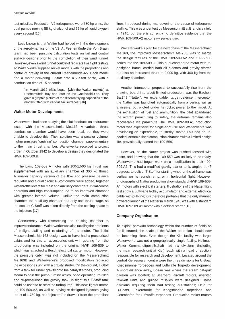
The De Havilland “Ghost” Lancastrian taking off with the help of two Walter 109-500 take-off packs.(Courtesy The National Archives, Kew)

63
Walterwerke KG
the test bed withstood the blast very well. The damage was done by the armoured glass windows being blown into the control room” [43].
The stories of the other Walter staff brought to the UK were mixed. Once the Royal Navy’s Explorer and Excalibur submarine projects had run their main course, the Walter team at Barrow-in-Furness was disbanded in 1949. Hellmuth Walter emigrated to America and began a very successful career with the Worthington Corporation. With the exception of Gunter Oestreich who stayed in the UK, the others returned to Germany. At Westcott the other German personnel, initially unable to show their full potential in the subordinate roles they were given, gradually became more fully integrated. The thought of previous enemies taking major roles began to fade, and the Germans subsequently became regarded largely with respect and affection [44].
Summary
The influence of German scientific work done at Walterwerke on British post-war developments has elicited a number of contrasting views. In his review of the Blue Streak, Roy Dommett stated “German technology solutions were apparent in the designs of all early rocket engines, but there were improvements being made to injectors and to the cooling systems for the chambers and nozzles” [45]. This view was supported by Wernimont et al. when they wrote that “England received significant influence from the Walter ATOs and the Walter 105-509 [sic] rocket engine... “ [46].
There is no doubt that in the late forties and fifties, many British scientists developed novel solutions to unique problems which owed no debt to any work previously done. However, it is
clear that even if data generated by the Germans during the war and captured by intelligence teams in the immediate post-war period was not directly employed, British scientific teams were analysing German technology.
German and British scientists did work closely together in the months after the cessation of hostilities. Walterwerke’s expertise in hydrogen peroxide technology was a great help in developing strands of British Naval systems. Even into 1946, trips were still being made over to Germany to seek help from German sources who had worked on original Walter projects [47].
Writing in the 1950s, Weyl was slightly more outspoken in his view. “It is no use denying that, despite immense efforts, the Western powers have produced few, if any, new ideas; nearly all current developments are based upon German work, whatever ministers and publicity departments may assure the public. The work done with so much money and men has produced nothing more than improved manufacture and testing techniques, better detail design with some new features, and a collection of practical experience” [30].
The actual situation probably lies somewhere in the middle ground. It can be generally acknowledged that developments occurring beyond 1948 were not the direct application of German technical achievement, rather completely innovative strands which broke new ground.
The last word can be given to Harry Sunley, who as part of the RAE had examined German material at Walterwerke, who later worked with the Germans at MoS Trauen, and who went on to work at Armstrongs, and so had direct experience of these
Walter 109-509 steam turbine being used as the drive to test an Armstrong Siddeley liquid oxygen pump (foreground). (Courtesy of Rolls Royce Heritage Trust, (c) Rolls-Royce plc)
64
Shamus Reddin
times. He gave a pertinent summary of the position of Walter war-time developments in British rocketry:
“On the early British post-war projects, with the exception of the Alpha, the aim was the provision of devices that had
1. E. Kruska and E. Rössler, “Walter U-Boote”, J.F. Lehmanns, München, 1969.
2. T. Benecke and A. Quick, “A History of German Guided Missile Development”, AGARD, Munich, 1957.
3. H. Walter, “Bericht über die R-Triebwerke auf Grundlage des T-Stoffes”, R-Antriebe, Schriften der Deutsche Akademie der Luftfahrtforschungs, pp.Heft 1071, Nr.82, 1943.
4. A. Davidson, T. N. Blockley and B. Vigers, “Hydrogen Peroxide Works of Otto Schickert & Co at Bad Lauterberg and Rhumspringe”, BIOS 294, 1945.
5. C.M. Hall, “Report on Visit to H. Walter Kommanditgesellschaft Kiel to Investigate Underwater Propulsion of Submarines”, Director of Naval Construction, 1945.
6. W. Ahlborn, “Flugmessungen an einem Stück des Flugzeugmusters FW.56 mit Walter-Rückstoßgerät”, Deutsche Versuchsanstalt für Luftfahrt, Berlin-Adlershof, 1939.
7. A.P. Beeton, “Information on Walter Rocket Propulsion Systems from 1936 to 1945”, HEC 10670, 1946.
8. Bartelsen, “Progress of Development of the Propulsion Units RII-203 for Training Airplanes Me.163”, H. Walter Kommanditgesellschaft, Kiel, 1943.
9. W. Green, Rocket Fighter: Weapons Book #20, Purnell’s History of the Second World War, 1971.
10. J.E. Topps, “Hs.293 Glider Bomb Propulsive System”, Power Jets Report R.1041, 1944.
11. J. Waterhouse RN, “Loss of HMS Egret”, Letter to Admiralty, 1943. 12. Redenz, “Lebenslaufakte für Gerät 109-509.A”, H. Walter
Kommanditgesellschaft, Beerberg, 1944.13. K.W. Gatland, “Rocket Propulsion - Rocket-powered Interceptors:
Early Walter Bi-Fuel Engines”, Newnes Practical Mechanics, p.386, 1946.
14. C. Kell and H.L. Sunley, “The Walter 109-509A2 Bi-Fuel Aircraft Rocket Motor”, RAE Tech.Note Gas 2, 1946.
15. W.H. Riedel, “Rocket Development with Liquid Propellants”, Rolls Royce Heritage Trust, Derby, 2005.
16. W. Dornberger, “V2”, Hurst and Blackett, London, 1954. 17. Redenz, “Lebenslaufakte für Gerät 109-509.B”, H. Walter
Kommanditgesellschaft, Beerberg, 1944.18. B. Gooden, “Projekt Natter: Last of the Wonder Weapons”, Ian
Allen Publishing, Hersham, 2006. 19. E. Möller, “Marine Geheimprojekte: Hellmuth Walter und seine
Entwicklungen”, Motor Buch Verlag, Stuttgart, 2000. 20. A.D. Baxter, “Walter Rocket Motors for Aircraft”, RAE Tech.Note
Aero 1668, 1945. 21. N.M. Harris, “The Guided AA Rocket Enzian”, RAE Tech.Note RPD
6/47, 1945. 22. N. Coles, “German Guided Missile Research”, CIOS XXXII-125,
1945.
a high safety and reliability standard - for manned and commercial use. The Me 163 had a poor safety record and most of the other devices, including the A4 were one shot. Thus having assimilated the principles, our problem was to turn these ‘conjuring tricks’ into reliable hardware” [48].
References
23. W.S. Farren, “Farren Mission to Germany”, MAP Report, 1945. 24. N. Rankin, “Ian Fleming’s Commandos: The Story of 30 Assault
Unit in WWII”, Faber & Faber, London, 2011. 25. D. Nutting, “Attain by Surprise; Capturing Top Secret Intelligence in
World War II”, David Colver, 2000.26. I.C. Aylen, “Walterwerke: A History of the Occupation by the Allies”,
Admiralty, ADM-265/71, 1945.27. H.W. Faulkner, “Future of the Walter Werke at Kiel”, Signal
913/A/1179, 1945. 28. O. Lascelles, “HMS Meteorite Trials Report 17th March-30th April
1949”, Admiralty, 1949.29. R.C. Murray, “Developments in Liquid Bi-Fuel Rocket Technique at
the MoS Establishment Trauen”, RAE Tech.Note Chem.986, 1946.30. A.R. Weyl, “The Truth about German Guided Weapons”, Flight,
69, p.648, 1956. 31. A. Jeffs, Interview, 11 April 2001.32. G. Taylor, Interview, 2 April 2011.33. L.W. Broughton, R.J. Newton and A. Dick, “Development of the
Combustion Chamber for the Alpha Rocket Motor”, RAE Tech.Note Aero 2188, 1947.
34. P. Stokes, Interview, 15 August 2012.35. J. Swan, “Flight Trials of a Rocket-propelled Transonic Research
Model”, Aeronautical Research Council R&M 2835, 1950. 36. Staff, “Rocketry at Westcott”, Flight, p.190, August 1947. 37. A.V. Cleaver, “De Havilland Trials of Rocket Assited Take-Off on
Lancastrian”, De Havilland Engine Co. Ltd., 1947.38. V. Cleaver, “Rockets and RATO”, Flight, p.482, November 1950. 39. Golovine, “Lloyd Committee Minutes,” Armstrong Siddeley, 1945.40. PA1716/1/9/10, “Walter Turbopump on Snarler LOX Pump”,
Armstrong Siddeley Photograph, 1946. 41. S. Allen, “Tests of German Rocket Motor Fuel Pump”, Armstrong
Siddeley, PA1716/1/11/28, 1947.42. U.M. Barske, “High Pressure Pumps for Rocket Motors”, RAE
Tech.Note RPD 40, 1950. 43. A.D. Baxter, Venturi, Vol.1 No.5, December 1947. 44. J. Becklake, “German Engineers: Their Contribution to British
Rocket Technology after the War”, in History of Rocketry and Astronautics AAS Volume 22, 1998.
45. R. Dommett, “The Blue Streak Weapon”, in British Rocketry Oral History Project Conference, Charterhouse, Surrey, 2004.
46. E. Wernimont, M. Ventura, G. Garboden and P. Mullens, “Past and Present Uses of Rocket Grade Hydrogen Peroxide”, in International Hydrogen Peroxide Propulsion Conference, West Lafayette, USA, 1999.
47. T.M. Unwin, “Report on Visit to Dr. Kurt Kreuter, of the Technische Hochschule Hannover”, ADM-178/392, 1946.
48. H.L. Sunley, Letter to John Becklake, 1993.
* * *
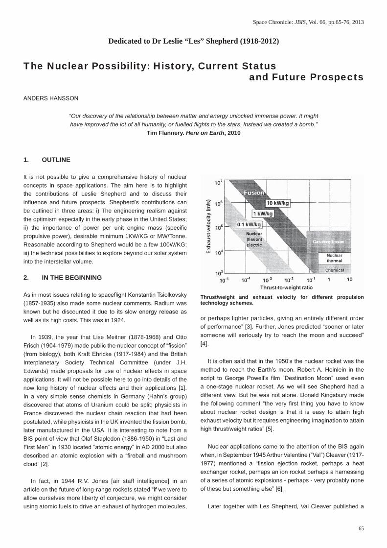
65
The Nuclear Possibility: History, Current Status and Future ProspectsSpace Chronicle: JBIS, Vol. 66, pp.65-76, 2013
1. OUTLINE
It is not possible to give a comprehensive history of nuclear concepts in space applications. The aim here is to highlight the contributions of Leslie Shepherd and to discuss their influence and future prospects. Shepherd’s contributions can be outlined in three areas: i) The engineering realism against the optimism especially in the early phase in the United States; ii) the importance of power per unit engine mass (specific propulsive power), desirable minimum 1KW/KG or MW/Tonne. Reasonable according to Shepherd would be a few 100W/KG; iii) the technical possibilities to explore beyond our solar system into the interstellar volume.
2. IN THE BEGINNING
As in most issues relating to spaceflight Konstantin Tsiolkovsky (1857-1935) also made some nuclear comments. Radium was known but he discounted it due to its slow energy release as well as its high costs. This was in 1924.
In 1939, the year that Lise Meitner (1878-1968) and Otto Frisch (1904-1979) made public the nuclear concept of “fission” (from biology), both Kraft Ehricke (1917-1984) and the British Interplanetary Society Technical Committee (under J.H. Edwards) made proposals for use of nuclear effects in space applications. It will not be possible here to go into details of the now long history of nuclear effects and their applications [1]. In a very simple sense chemists in Germany (Hahn’s group) discovered that atoms of Uranium could be split; physicists in France discovered the nuclear chain reaction that had been postulated, while physicists in the UK invented the fission bomb, later manufactured in the USA. It is interesting to note from a BIS point of view that Olaf Stapledon (1886-1950) in “Last and First Men” in 1930 located “atomic energy” in AD 2000 but also described an atomic explosion with a “fireball and mushroom cloud” [2].
In fact, in 1944 R.V. Jones [air staff intelligence] in an article on the future of long-range rockets stated “if we were to allow ourselves more liberty of conjecture, we might consider using atomic fuels to drive an exhaust of hydrogen molecules,
or perhaps lighter particles, giving an entirely different order of performance” [3]. Further, Jones predicted “sooner or later someone will seriously try to reach the moon and succeed” [4].
It is often said that in the 1950’s the nuclear rocket was the method to reach the Earth’s moon. Robert A. Heinlein in the script to George Powell’s film “Destination Moon” used even a one-stage nuclear rocket. As we will see Shepherd had a different view. But he was not alone. Donald Kingsbury made the following comment “the very first thing you have to know about nuclear rocket design is that it is easy to attain high exhaust velocity but it requires engineering imagination to attain high thrust/weight ratios” [5].
Nuclear applications came to the attention of the BIS again when, in September 1945 Arthur Valentine (“Val”) Cleaver (1917-1977) mentioned a “fission ejection rocket, perhaps a heat exchanger rocket, perhaps an ion rocket perhaps a harnessing of a series of atomic explosions - perhaps - very probably none of these but something else” [6].
Later together with Les Shepherd, Val Cleaver published a
The Nuclear Possibility: History, Current Status and Future Prospects
Dedicated to Dr Leslie “Les” Shepherd (1918-2012)
ANDERS HANSSON
“Our discovery of the relationship between matter and energy unlocked immense power. It mighthave improved the lot of all humanity, or fuelled flights to the stars. Instead we created a bomb.”
Tim Flannery. Here on Earth, 2010
Thrust/weight and exhaust velocity for different propulsion technology schemes.

66
Anders Hansson
series of, for their time and in public, remarkable insights, known normally as the “Shepherd-Cleaver papers”. Their arguments can be outlined without their technical nature in four points:
1) Chemical rockets are the most likely in the “near future”;
2) The nuclear rocket was “at the moment” not technically feasible due to lack of engineering;
3) Both solid and gaseous reactors are possible for both with hydrogen as propellant
4) Ion propulsion would be linked to nuclear propulsion.
3. THE EARLY USA SITUATION
This realistic, some would call it “pessimistic”, view contrasted with the optimistic approach of Enrico Fermi (1901-1954) asking where all the extraterrestrials are. The Fermi view had its roots in work on nuclear propulsion during The Manhattan Project by Stanislaw Ulam (1909-1984) and Frederick de Hoffman (1924-1989). Already in 1945 the Advanced Research Projects Agency (ARPA) began sponsoring their work. The reason was not so much the development for space but for the use of “explosive propulsion” to transport nuclear weapons. The firm General Atomic began in 1955 by a group of physicists led to Frederick Hoffmann attempting to keep the Manhattan Project work spirit going in a more commercial setting, a sign of shifting political priorities.
On the day of Sputnik II was launched (with the dog Laika, 3 November 1957) General Atomic issued “Note on the Possibility of Nuclear Propulsion of a Very Large Vehicle at Greater than Earth Escape Velocities”. This became “Orion” and it was estimated that a craft could be ready by 1963-64 and “cost approximately $500,000,000” [7].
As is well known, the 1963 Atmospheric test-ban treaty ended the environment of “free testing”. What is less known is that “although small fusion bombs never materialised, the origin and development of Orion were intimately related to the origins and development of the hydrogen bomb” [8]. Ulam took it further. “On April 1, 1958 he wrote a brief Los Alamos report “On the Possibility of Extracting of Energy from Gravitational Systems by Navigating Space Vehicles...amplifying a limited supply of fuel and propellant by using computational intelligence” [9].
At the time of George Dyson’s book the ideas Ulam was hinting at remained classified but the report does mention a “4,000 ton vehicle “travelling at “20 km a second.”
For the administrators other issues had priority. This was “Project Rover, initiated in 1955 in an attempt to develop a nuclear powered Inter Continental Ballistic Missile (ICBM) capable of delivering first-generation thermonuclear warheads” [10].
The official start of the nuclear propulsion program excludes the thinking within the Manhattan Project and began with the studies conducted by Theodore von Karman for General
H (“Hap”) Arnold (1896-1950) just at the end of the war. As was mentioned by Bob Parkinson in “A Life Honoured” [11] both Shepherd and von Karman took a very active part in the formation of the International Academy of Astronautics (IAA) in 1959. Returning to 1945, the first study by von Karman “Where we stand” suggested “a nuclear rocket for interstellar navigation” but already the second one called “Toward New Horizons” at the end of that year, indicated “the immense difficulties in controlling the release of nuclear energy”. While being pessimistic on rockets in the near term the Von Karman study recommended “a pilotless atomic airplane”. This took the form of the NEPA - Nuclear Energy for the Propulsion of Aircraft - that began in USA in April 1946. Recently Cranfield University has returned to nuclear powered aircraft but now to take chemically propelled aircraft over long distance eliminating chemically powered cruise. “Today, it is possible to travel across France in a nuclear powered train...nuclear power could be used to generate hydrogen from seawater with very little environmental impact. This would require new infrastructure. Nevertheless, if it would be made available at about two hundred major airports, this would probably be sufficient...alternatively a small airborne nuclear heat source could be developed for the gas turbine. This idea was studied extensively in the 1950’s when it was taken very seriously. However, the concept raises many challenges and not all of them are technical” [12].
Robert Serber from the Manhattan Project, moved to RAND when the then US Army Air Force set the organisation up, and after three months in July 1946 produced a three page memo on methods to produce thrust from nuclear energy. Serber listed fission fragments, alpha, beta particle momentum as well as heat exchange. The last was recommended.
In the same month the North American Aviation Aerophysics Laboratory produced a report on a rocket based on a graphite core reactor. The work generated a study contract from the US Army Air Force but since the North American team did not have access to Manhattan or NEPA work they overestimated the uranium needed.
NEPA itself was under attack by now and later in 1948 Vannevar Bush as well as Robert Oppenheimer (1904-1967) argued against nuclear powered aircraft, and it officially ended in 1951.
The need for any success: radiation shielding and heat resisting materials remain. The 1969 assumption that a nuclear rocket could be in operation by the late 1970’s was far too optimistic. The fact that the nuclear rocket had been transferred from the USAF to NASA already in 1958, at the start so to say, indicates that by then the engineering of nuclear weapons had progressed in the USA to a level where mass was no longer the central issue, but launching time etc. was. Already in 1947 Luis W Alvarez had concluded that “if you read in the papers some years hence that an atomic powered

67
The Nuclear Possibility: History, Current Status and Future Prospects
rocket has been sent to the moon, you can at least be sure that its designers chose atomic power only after many misgivings, and that decision was based not on the attractiveness of this new energy source, but only after the realization that it was fantastically difficult or expensive to do the job with chemical propellants” [13].
The lightweight hydrogen warheads postulated in the summer of 1956 generated the Polaris program’s solid rocket propellant system, and smaller launchers. On April 15, 1954, Dr Norris E Bradbury the Director of the Los Alamos Laboratory had established a new Division - the Nuclear Propulsion - to research materials and reactor designs for possible nuclear rockets. A similar Division was established at Livermore as well. The stated aim was for an upper stage nuclear rocket and is known as “Project Rover” and was in a sense the first tinkering phase of nuclear propulsion. The Project Rover results were impressive. For example, the Los Alamos Lab constructed the “Phoebus II”, a reactor that was tested at 4 GigaW for 12.5 minutes, with a power density around 1.3 MW/Litre.
In the beginning this was a joint project between the Atomic Energy Commission and NASA. However in 1958 NASA created NERVA (Nuclear Engine for Rocket Vehicle Applications), a program that operated until 1972. Westinghouse and Aerojet formed the industrial partners. There are several excellent articles on the history of NERVA [14].
In all, 23 tests took place at a test site in Nevada and reactors ranged from 300 to 200,000 MW.
4. A NEW BEGINNING IN THE UNITED STATES
In the 1980‘s the Department of Defence (DoD) and United States Air Force (USAF) aimed for a nuclear core with a higher thrust-to-weight ratio than NERVA. This generated the particle bed reactor and lasted until 1993 with a budget of some $40M
per year called SNTP (Space Nuclear Thermal Propulsion). In 1986 the German pebble bed program had closed due to jamming in the fuel and the concept was sold to South Africa. Shepherd always claimed that the concept had originated in Britain.
Another USAF developed program was CERMET [15] that used fast neutrons (that is over 1 Mev). CERMET was an undertaking involving Pratt & Whitney, Aerojet and the Centre for Nuclear Research in Idaho. Tests indicated that CERMET fuel is significantly more robust than NERVA without increasing the mass while providing longer reactor life. This is an issue discussed even at present, as late as the Propulsion Conference in 2012.
The following Table 1 [16] compares the three types of reactor concepts.
The engine using a particle-bed reactor has higher performance and is lighter than the NERVA, but NERVA is more developed [37]. CERMET is a possible fast-reactor concept that can also be reused.
Only the Space Nuclear Auxiliary Power - SNAP - 10A reactor was put into orbit in 1965 by the USA while the USSR flew some 38 nuclear reactors as well as Radioisotope Thermoelectric Generators (RTGs) like on the failed Mars ‘96 mission.
In addition to SNAP -10A that continued up to the early 1970‘s the USA investigated the Space Power Unit Reactor (SPUR), also known as the SNAP-50/ SPUR, being aimed for nuclear electric. In contrast to SNAP where the one year operational aim had to be achieved by a ground based twin SNAP-50/SPUR reached 1 MWe (compared to 500 We)
The next step between 1983-94 is the SP-100 program scalable from some 10 KWe to 1000 KWe.
TABLE 1: Comparison of Possible Near-Term Concepts for Reactors. Characteristics NERVA Particle Bed CERMET Power MW 1,570 1,945 2,000
Thrust, N 334,061 333,617 445,267
Propellant H2 H2 H2
Fuel element Solid rod Porous Particle bed Solid rod
Maximum propellant temperature, K 2,361 3,200 2,507
I sp, s 825 971 930
Chamber pressure, MPa 3,102 6,893 4,136
Nozzle expansion ratio 100 125 120
Engine mass, kg 10,138 1,705 9,091
Total shield mass, kg 1,590 1,590 1,590
Engine thrust/weight (no shield) 3.4 20.0 5.0

68
Anders Hansson
The fundamental problem with all such programs has been the stop-and-go nature. The theory is clear. Nuclear rockets could have a specific impulse three times of the optimal chemical rocket (liquid hydrogen-liquid oxygen) but as can be seen by this history the nuclear engine performance has been stuck at about twice that of the chemical rocket. In fact, already Rover/NERVA showed that multi-mega-watt systems are possible. It is perhaps not surprising that USA is now returning to NERVA that originated at Oak Ridge. Another concept was known as “DUMBO” that flourished at Los Alamos around 1958 and used a then new high thrust weight design.
However, others still support CERMET and nuclear thermal.
5. RADIOISOTOPE POWER SYSTEMS
In contrast to reactor-based systems, Plutonium 238 is the most used isotope for these power systems (at least partially since it is not used in nuclear weapons). Since 1961 seven generations of these systems have been used by the United States. Missions have been aimed at the moon, Venus, Mars, Jupiter and more. And during the first ten years only three missions failed but the abort systems worked.
Future possibilities include missions to the oceans of Europa, the liquid lakes of Titan and touring the rings of Uranus. Therefore, there can be no argument that this type of nuclear technology has made a significant contribution to our knowledge of our solar system.
Further advances are possible [17].
Recently, ESA has initiated activities to establish radio isotopic activity in Europe - both heaters (based on 40g Plutonium Dioxide) and thermoelectric (on the level of 4.5 Kilos Plutonium Dioxide). There are alternatives like Americium and at the ESA Council in Naples, 2012, the UK decided to
contribute £18 million to “the development of space nuclear power sources”.
However, according to Spaceflight magazine, July 2013, “lack of radioisotope materials for the 2020 Mars Curiosity 2.0 mission has forced a switch to solar power for the lander” [18]. The news indicates that the situation is not good in the United States even for the most successful part of nuclear space applications.
6. PROJECT PROMETHEUS
In 2003 it appeared that NASA would return to nuclear reactors in space. The reason was a mission – Jupiter Icy Moons Orbiter – JIMO – to Callisto, Gannymede and Europa (leaving only Io out of the four moons of Jupiter discovered by Galileo in 1610).
The idea was to use the power to make a “flyto”, not the normal “flyby” and reach the Jupiter system in only eight years and deploying landers and returning broadband-style data.
The reactor would not be active at launch (different from Plutonium in RTGs that are active when constructed) and only activated when JIMO had reached escape velocity. The UN rule is 1000-2000 KM orbit.
However, after some $464M, the program got cancelled in the summer of 2005. A further $90M got used for cancelled contracts.
The National Research Council’s Space Studies Board and Aeronautics and Space Engineering Board concluded in 2008 in the report “Launching Science” that JIMO should be regarded as “an example of the risks associated with pursuing ambitious, expensive space science missions. The NEXT-NASA’s Evolutionary Xenon Thruster Ion Propulsion prospect suvived but nuclear electric is now behind nuclear thermal again in USA priority.
Artist’s concept of the Jupiter Icy Moons Orbiter (JIMO). (NASA)
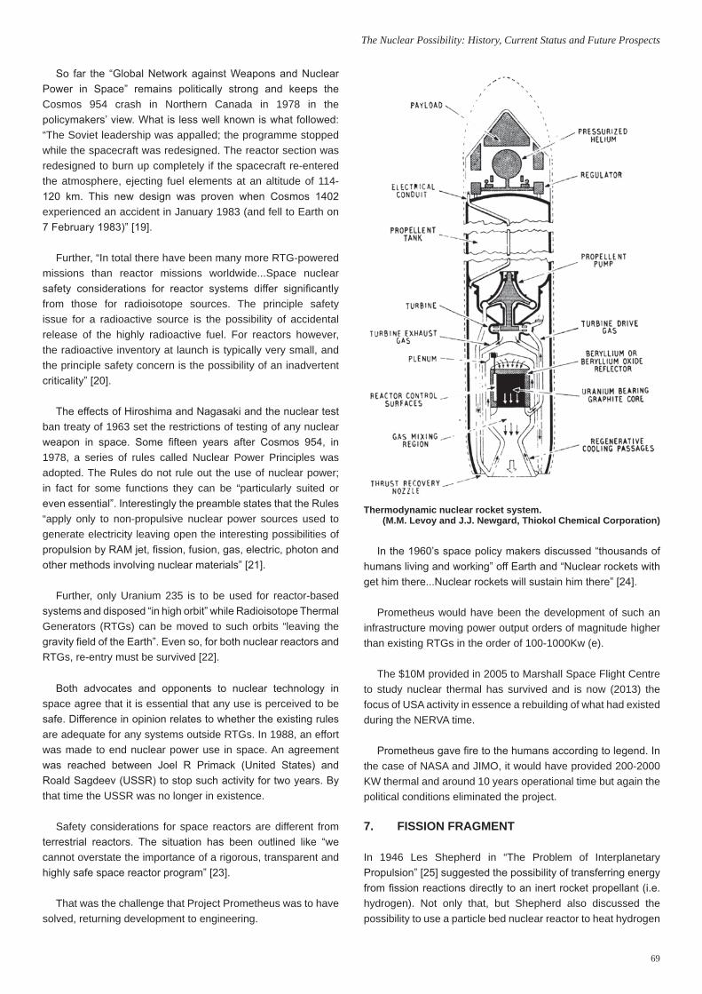
69
The Nuclear Possibility: History, Current Status and Future Prospects
So far the “Global Network against Weapons and Nuclear Power in Space” remains politically strong and keeps the Cosmos 954 crash in Northern Canada in 1978 in the policymakers’ view. What is less well known is what followed: “The Soviet leadership was appalled; the programme stopped while the spacecraft was redesigned. The reactor section was redesigned to burn up completely if the spacecraft re-entered the atmosphere, ejecting fuel elements at an altitude of 114-120 km. This new design was proven when Cosmos 1402 experienced an accident in January 1983 (and fell to Earth on 7 February 1983)” [19].
Further, “In total there have been many more RTG-powered missions than reactor missions worldwide...Space nuclear safety considerations for reactor systems differ significantly from those for radioisotope sources. The principle safety issue for a radioactive source is the possibility of accidental release of the highly radioactive fuel. For reactors however, the radioactive inventory at launch is typically very small, and the principle safety concern is the possibility of an inadvertent criticality” [20].
The effects of Hiroshima and Nagasaki and the nuclear test ban treaty of 1963 set the restrictions of testing of any nuclear weapon in space. Some fifteen years after Cosmos 954, in 1978, a series of rules called Nuclear Power Principles was adopted. The Rules do not rule out the use of nuclear power; in fact for some functions they can be “particularly suited or even essential”. Interestingly the preamble states that the Rules “apply only to non-propulsive nuclear power sources used to generate electricity leaving open the interesting possibilities of propulsion by RAM jet, fission, fusion, gas, electric, photon and other methods involving nuclear materials” [21].
Further, only Uranium 235 is to be used for reactor-based systems and disposed “in high orbit” while Radioisotope Thermal Generators (RTGs) can be moved to such orbits “leaving the gravity field of the Earth”. Even so, for both nuclear reactors and RTGs, re-entry must be survived [22].
Both advocates and opponents to nuclear technology in space agree that it is essential that any use is perceived to be safe. Difference in opinion relates to whether the existing rules are adequate for any systems outside RTGs. In 1988, an effort was made to end nuclear power use in space. An agreement was reached between Joel R Primack (United States) and Roald Sagdeev (USSR) to stop such activity for two years. By that time the USSR was no longer in existence.
Safety considerations for space reactors are different from terrestrial reactors. The situation has been outlined like “we cannot overstate the importance of a rigorous, transparent and highly safe space reactor program” [23].
That was the challenge that Project Prometheus was to have solved, returning development to engineering.
In the 1960’s space policy makers discussed “thousands of humans living and working” off Earth and “Nuclear rockets with get him there...Nuclear rockets will sustain him there” [24].
Prometheus would have been the development of such an infrastructure moving power output orders of magnitude higher than existing RTGs in the order of 100-1000Kw (e).
The $10M provided in 2005 to Marshall Space Flight Centre to study nuclear thermal has survived and is now (2013) the focus of USA activity in essence a rebuilding of what had existed during the NERVA time.
Prometheus gave fire to the humans according to legend. In the case of NASA and JIMO, it would have provided 200-2000 KW thermal and around 10 years operational time but again the political conditions eliminated the project.
7. FISSION FRAGMENT
In 1946 Les Shepherd in “The Problem of Interplanetary Propulsion” [25] suggested the possibility of transferring energy from fission reactions directly to an inert rocket propellant (i.e. hydrogen). Not only that, but Shepherd also discussed the possibility to use a particle bed nuclear reactor to heat hydrogen
Thermodynamic nuclear rocket system.(M.M. Levoy and J.J. Newgard, Thiokol Chemical Corporation)
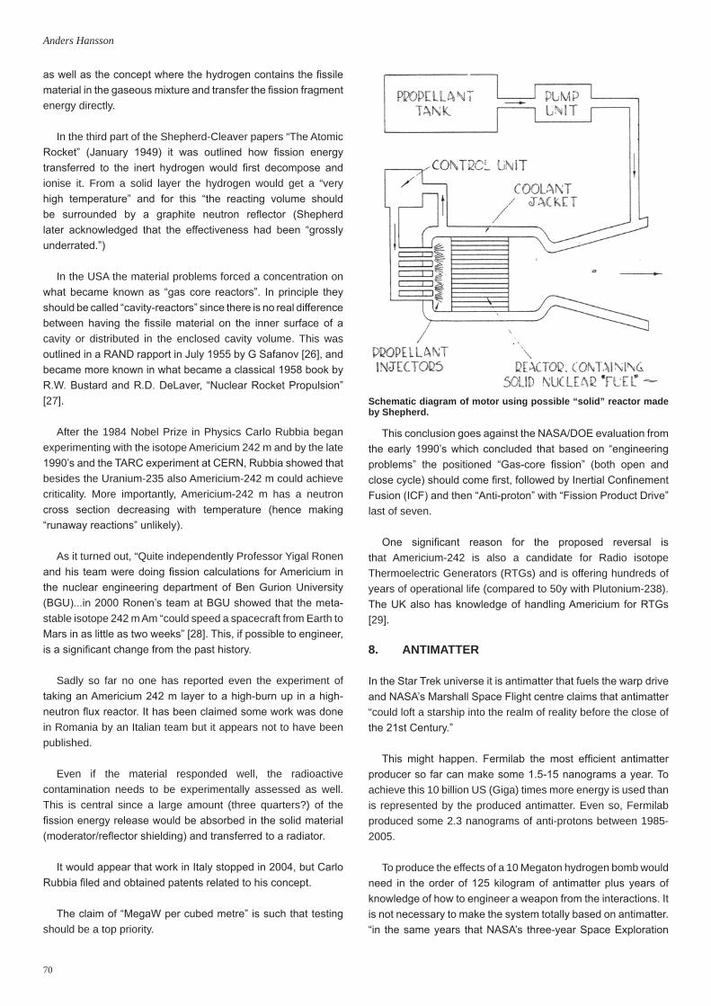
70
Anders Hansson
as well as the concept where the hydrogen contains the fissile material in the gaseous mixture and transfer the fission fragment energy directly.
In the third part of the Shepherd-Cleaver papers “The Atomic Rocket” (January 1949) it was outlined how fission energy transferred to the inert hydrogen would first decompose and ionise it. From a solid layer the hydrogen would get a “very high temperature” and for this “the reacting volume should be surrounded by a graphite neutron reflector (Shepherd later acknowledged that the effectiveness had been “grossly underrated.”)
In the USA the material problems forced a concentration on what became known as “gas core reactors”. In principle they should be called “cavity-reactors” since there is no real difference between having the fissile material on the inner surface of a cavity or distributed in the enclosed cavity volume. This was outlined in a RAND rapport in July 1955 by G Safanov [26], and became more known in what became a classical 1958 book by R.W. Bustard and R.D. DeLaver, “Nuclear Rocket Propulsion” [27].
After the 1984 Nobel Prize in Physics Carlo Rubbia began experimenting with the isotope Americium 242 m and by the late 1990’s and the TARC experiment at CERN, Rubbia showed that besides the Uranium-235 also Americium-242 m could achieve criticality. More importantly, Americium-242 m has a neutron cross section decreasing with temperature (hence making “runaway reactions” unlikely).
As it turned out, “Quite independently Professor Yigal Ronen and his team were doing fission calculations for Americium in the nuclear engineering department of Ben Gurion University (BGU)...in 2000 Ronen’s team at BGU showed that the meta-stable isotope 242 m Am “could speed a spacecraft from Earth to Mars in as little as two weeks” [28]. This, if possible to engineer, is a significant change from the past history.
Sadly so far no one has reported even the experiment of taking an Americium 242 m layer to a high-burn up in a high-neutron flux reactor. It has been claimed some work was done in Romania by an Italian team but it appears not to have been published.
Even if the material responded well, the radioactive contamination needs to be experimentally assessed as well. This is central since a large amount (three quarters?) of the fission energy release would be absorbed in the solid material (moderator/reflector shielding) and transferred to a radiator.
It would appear that work in Italy stopped in 2004, but Carlo Rubbia filed and obtained patents related to his concept.
The claim of “MegaW per cubed metre” is such that testing should be a top priority.
This conclusion goes against the NASA/DOE evaluation from the early 1990’s which concluded that based on “engineering problems” the positioned “Gas-core fission” (both open and close cycle) should come first, followed by Inertial Confinement Fusion (ICF) and then “Anti-proton” with “Fission Product Drive” last of seven.
One significant reason for the proposed reversal is that Americium-242 is also a candidate for Radio isotope Thermoelectric Generators (RTGs) and is offering hundreds of years of operational life (compared to 50y with Plutonium-238). The UK also has knowledge of handling Americium for RTGs [29].
8. ANTIMATTER
In the Star Trek universe it is antimatter that fuels the warp drive and NASA’s Marshall Space Flight centre claims that antimatter “could loft a starship into the realm of reality before the close of the 21st Century.”
This might happen. Fermilab the most efficient antimatter producer so far can make some 1.5-15 nanograms a year. To achieve this 10 billion US (Giga) times more energy is used than is represented by the produced antimatter. Even so, Fermilab produced some 2.3 nanograms of anti-protons between 1985-2005.
To produce the effects of a 10 Megaton hydrogen bomb would need in the order of 125 kilogram of antimatter plus years of knowledge of how to engineer a weapon from the interactions. It is not necessary to make the system totally based on antimatter. “in the same years that NASA’s three-year Space Exploration
Schematic diagram of motor using possible “solid” reactor made by Shepherd.

71
The Nuclear Possibility: History, Current Status and Future Prospects
Initiative was cancelled (1992), a group from Pennsylvania State University for Elementary Particle Science observed large fission and neutron yields from anti-proton annihilation at rest in a natural uranium target” [30].
This makes anti-proton catalysed fusion a possible source for fast transport in the Solar System and further...“A spacecraft with such a propulsion system would make a mission to Jupiter possible within the present timescale of chemical based Mars missions.
Since that time development of the Ion Compressed Antimatter Nuclear propulsion device – ICAN-II has not moved much further but the offered trip time to Mars around 48 days makes further work a signal of serious interest in sending humans to Mars. Or as stated by K.F. Long “faced with such fantastic potential, we have no reason not to try” [31].
9. FUSION
After harnessing nuclear fusion processes for the “hydrogen bomb” interest began to move to more practical power use. When President Juan Peron of Argentina announced that “a German scientist, Ronald Richter, had succeeded in the controlled release of atomic energy at super high temperatures of millions of degrees Celsius without using uranium fuel” [32] the then USSR was galvanised into action. This was 1951. The point to remember is that there exists no theoretical limit to the hydrogen bomb.
When the respected magazine Nature claimed seven years later that the UK had achieved “temperatures of tens of millions of degrees Celsius and neutrons of thermonuclear energy” nuclear fusion appeared to be on the way but not as a weapon. In fact, the Nature note stated that “the neutron flux so far obtained was insufficient” but as Sir John Cockcroft lamented, “We were not believed”.
As we know now, it took much more time and the present International Thermonuclear Experimental Reactor - ITER - that began construction in 2009 was conceived in a series of INTOR (International Tokamak Reactor) workshops between 1978-88. During this period the then USSR leader Gorbachev recommended to President Reagan in Geneva in 1985 that they combine their efforts and ITER today comprises the EU, Japan, Russia, USA, South Korea, PR China and India together consisting of more than half the Earth’s human population.
The progress “Fusion research has now progressed to the point that conditions necessary for an energy-producing fusion reactor have been approached, and tens of thousands of kilowatts of thermal power have been produced by fusion experiments, albeit only for seconds. Hundreds of industrial scientists and engineers in companies around the world are preparing to manufacture the various sophisticated components that will ultimately be assembled at Cadarache” [33].
It remains to be seen what the Cadarache establishment in France will do for any “fusion industry” but as Leslie Shepherd pointed out due to its engineering complexity, a fusion industry on Earth is a necessary step for real nuclear fusion propulsion. A pure self-sustaining fusion needs a plasma volume more than three times ITER.
The good news is “After two weeks of intense technical discussion, mitigated by informal discussions over coffee twice a day, by a couple of wine and cheese gatherings at the end of the day and by dinners hosted by the Japanese and by the Soviets...the spirit of international camaraderie and trust that was one of the greatest achievements of the INTOR Workshop began to take root” [34].
The bad news is that besides being late (2019?) ITER will become a “skeleton device” with only Deuterium-Tritium plasma aimed for 2026. The cost is projected around $22 billion US (Giga) but very uncertain.
Since magnetic fusion devices produced 16 million Watts of power in 1997, it would appear that power extraction and material damage would be of more importance than high energy- gain plasma physics that increasingly appears to be the centre of ITER. In 1991 Shepherd had postulated that magnetic type fusion would “have to be in the mass class of oil supertankers.” The central reason for such large structures is the energy deposited in structures (both from kinetic energy and captive energy).
Shepherd speculated that not until the latter half of this our 21st Century would an industry be established based on fusion and this could produce needed He3 (some 10 tonnes per year) with no need for lunar mining of Jovian atmosphere (as for the BIS Daedalus Project) [35]. Against this view we have for example Ray Erikson “Like it or not, atomic engines are absolutely necessary for human operations beyond the Moon and desirable for economic operations in lunar space. They will never be launched from earth but could be built on the Moon or an orbital spaceport” [36].
The advantage of the D + He3 reaction is well known (the significant reduction in neutrons, but side reactions would generate them, limiting the shielding to bremsstrahlung) and Shepherd calculated that one tonne of He3 could eject around 10,000 tonnes of propellant at a velocity of 50 Km per second. A modular aneutronic fusion engine is being investigated at Princeton, USA as well as by the US Navy.
In the long term, when it is possible to make nucleons (or quarks) in a manner similar to the present “atomic engineering” the nuclear fusion prospect will be opened up. At present it is suprisingly limited in the phenomena under investigation. This even more so if the need for small specific mass for space applications are considered.
Research on different systems is going on in what is becoming
72
Anders Hansson
Condensed Matter Nuclear Science illustrated by LENUCOLL, in Illinois. This is controversial even at the level of 3-5 KW with claims by Rossi in the MW range regarded as a return to the “Cold Fusions” era, or even ZETA and the Nature debate. High energy manipulation at present needs large volumes and large mass, on the scale of a nuclear powered submarine.
One reason for the size of magnetic contained fusion of the ITER type is the need for more constant operation a requirement not so critical for propulsion. Even so, it was recently concluded that “while it seems likely that we can explore well into the Kuiper Belt without new energy sources, something like compact fusion may ultimately be needed for Explorer robot to truly succeed. However, looking in the MM-wave/IR for narrow-beam communication systems may reveal that Extra Terrestrials have found compact fusion” [37].
At the end of September 2013, the National Ignition Facility in California announced that they have managed to extract more energy from a fusion reaction than they had put into it. This announcement demonstrates the feasibility of inertial confinement fusion but the scale of the Facility, with its 192 laser beams, shows how large existing systems have to be with present engineering.
10. NUCLEAR PULSE
As stated before, during the post-1945 “nuclear promise” era the use of nuclear weapons, but named “pulse” for propulsion was researched intensively. The project best known based on the concept is Orion but there were more [38]. Orion itself operated between 1961-66 including chemical testing.
Two basic types of nuclear pulse propulsion concepts are discussed:
• external, with pusher plate or Magnetic Field;
• internal;
but all have significant engineering issues [39].
During the laser fusion “promise” era an unofficial study SIRIUS (a spacecraft propelled by nuclear pulse) was produced. The launch mass of the vehicle was 20 metric tons with half being payload and the mass of the laser for driving the fusion capsules “only 500 kg”. Later Lawrence Livermore National Lab produced a more realistic and huge spacecraft VISTA [40].
Los Alamos National Lab produced an Orion concept MEDUSA, and the claim “that MEDUSA’s net environmental impact is less than NERVA” [41]. However, against this can be set the fact that Solem suggests starting the engine at the Lagrange point.
11. MATERIAL PROBLEMS
At the time when the BIS were the first to discuss nuclear
propulsion and power in public seriously very little was known of reactions in different materials from radiation.
It is possible to claim that Admiral Hyman Rickover, Director of Naval Reactors in the United States made the most central decision when selecting solid uranium oxide, enriched Uranium 235 for the first nuclear submarine, USS Nautilus.
Solid uranium fuel is inherently difficult to engineer. Not only does the heat and nuclear radiation damage the material, the rods have to be replaced after such a short time that only between 3-5% of energy in the uranium is used. Further, accumulation of Xenon 135 with its neutron management adds to the problem and so does long-lived trans-uranic elements.
Destruction of the material integrity of the fuel, also known as “burn up” is measured in “FIFA” (Fissions per Initial Fissile Atom) or FIMA (Fissions per Initial Metal Atom) where a metal atom is affected.
Understanding this micro structure is the limiting step for solid core reactors and is so difficult that liquid systems are advocated (especially liquid Fluoride Thorium Reactors). In fact, the use of solid fuel elements in NERVA resulted in significant heat transfer problems. Even the “DUMBO” reactor mentioned earlier would have provided more than 8KM/Sec (some 30% of the DUMBO vehicle would have been the reactor and propellant tank.)
The attraction of the gas core is the temperature increase that can be up to 22,000 degrees Centigrade and that Carbon or Tungsten would help in the heat transfer from the hydrogen gas and provide specific impulse (or in Shepherd’s technology, energy density) around 30-50 KM/sec. The disadvantage is the scale of the reactors. Present estimates are around 50 tonnes. Still not as large as fusion-based systems. Fusion systems have enormous specific impulse. For example BIS’ Project Daedalus, has an estimated specific impulse of 10,000 KM/sec.
Returning to material problems, in most terrestrial power reactors the FIRMA is low (in correspondence to the enrichment of Uranium 235). For space applications the FIRMA needs to be very high (For Carlo Rubbia’s engine, around 65-70%). In theory that means engineering coated particles and here the experience from fuel developed for Helium-cooled High Temperature Reactors could be a signpost together with highly enriched research reactors (that is if politically acceptable?)
In fact, NASA operated a significant test reactor outside Rover-NERVA for material testing and for a time the facility at Plum Brook had the highest neutron fluxes of any USA reactor. Such facilities became a tool of the so-called Cold War. From 1946 to 1961 the USSR constructed 15 and the USA 120. The Plum Brook facility had some 700 engineers and scientists investigating material response [42].

73
The Nuclear Possibility: History, Current Status and Future Prospects
In short, the database work began in 1963 and in 1973 with President Nixon’s “The Shuttle Doesn’t need NERVA” it ended, with the reactor in “stand by” to 1998. The peak was the construction of a Space Power Facility completed in 1968 to test a 15 Mega Watt reactor.
The USA had invested some $10B (Giga) between 1955-1971 with some 23 different reactor/engine designs. The last engine had a calculated specific impulse nearly three times those of Saturn V and twice the Space Transportation System. (That is 850 seconds).
Since some 7,000 different combinations of protons and neutrons forming nuclei exist many suggestions for better propulsion systems have been made. A case in point is the very toxic Protactinium 231. “Only a few hundred grams of Protactinium are available for study. This meagre amount was largely produced in England some thirty years ago where it was extracted from 30 tonnes of ore at a cost of half a million dollars” [43].
With such difficulties it is not surprising that Abram Ioffe in 1940 postulated that “if mastery of missile technology is a matter for the next fifty years, then the employment of nuclear energy is a matter of the next century” [44].
As it turned out, the USSR developed one of the biggest nuclear industries in the world.
12. USSR AND RUSSIAN FEDERATION
The significant size of the nuclear industry in the USSR has left some 38 reactors in Earth Orbit and some returning to Earth like “Cosmos-954” with Uranium and “Mars-96” with Plutonium.
The “Zarya” Design Bureau in Moscow was formed to develop nuclear rocket propulsion. The development included radio isotopic systems and Zarya developed the so-called “Orion”. Orion 1 is based on Plutonium-210 and provides some 20W (it is possible that an Orion 2 system was developed in the mid-1960’s.)
The knowledge related to the radioactive source itself rested with the All-Union Institute for Radiation Technology. (Later called the All-Russian Research and Development Institute for Technical Physics and Automation.) Design work for Soyuz 6 on 200-400W level appears to have been made by this Institute.
In 1972, Zarya merged with Krasnaya Zvezda (Red Star) that developed RTGs for Mars missions. Their proudest claim is for a Plutonium-238 system generating 60W over 6 years. It should be noted that the Research Institute for Atomic Reactors delivered the alpha radiation sources for NASA’s rovers, Spirit and Opportunity.
Returning to Krasnaya Zvezda, in 1960 the unit began
development of a power system for ocean reconnaissance satellites. This system was called BES-5 or Buk – Russian for beach, and was based on a fast neutron reactor. The reactor generated 100KW and 3KW electric based on 30KG of Uranium-235. In total 32 spacecraft between 1970-1988 used Buk. One launch failed and three accidents happened when the craft was being moved to inoperative or “burial” orbits.
Another project was TUE-5 or TOPOL(Poplar) named TOPAZ outside the USSR. This system generated 5KW electric and had an integrated reactor and thermal convertor. Both used Uranium-235 but only 11.5KG and generated 150KW of heat. Ground tests were carried out between 1970-73, and flight tested on Cosmos 1818 in 1987. This was too late in the life of the USSR for mass production of TOPOL/TOPAZ.
To complicate the situation Krasnaya Zvezda, together with Kurchatov Institute of nuclear energy was developing a power supply system called Jenesey (after the Siberian river) that outside the USSR got the name TOPAZ 2. One reason for this confusion is the similarities. 4.5-5.5KW electric; 115-135KW heat, Potassium-Sodium cooling and mass around a tonne. The difference is to be found in the aim. Jenesey was aiming for geo-stationary satellites and three year’s lifetime instead of the around 1 year for TOPOL/TOPAZ 1. The fuel for TOPAZ 2 was 27KG Uranium but with channels of 96% enriched uranium dioxide. Ground testing indicated a lifetime of 1.5 years but the end of the USSR reduced the funding for further development. It was this Jenesey system that formed the base for the collaboration between Russia, UK and the USA in NEPSTEP.
Later in the early 1990’s design work began on TOPAZ 100 or TOPAZ 3 for ultra-large geostationary satellites generating from 100-140KW electric but this project did not survive long. The Kurchatov Institute also developed the Romashka reactor-convertor. Here heat is converted into electricity without intermediate turbine machinery. The reactor was a high temperature one based on fast neutrons. It was operated through 1961-64 at a half KW based on Uranium-235 of 49KG. The ground tested system suffered from high heat losses and therefore low efficiency. Thermal batteries are now developed that could handle that part of the design. The USA had a similar project called STAR-R. Interestingly the Myasischev Experimental Design Bureau kept nuclear concepts going into at least the 1980’s in the form of MG-19. The reactor was to super heat hydrogen to reach orbit after turbo jets and scram jets had accelerated the vehicle to MACH 16.
In the USSR a solid core engine was ready for flight testing around the 30th anniversary of Sputnik 1. The thrust was given as 3.57 tons and the specific impulse as 920 seconds. The fuel was 7 kg of Uranium 235 at 90% enrichment, note that UN rules proscribe Plutonium for space reactors. It is claimed that the system operated over one hour in a ground test.
A gas core reactor, IV6-1 was tested at a lower power level.

74
Anders Hansson
As stated before, a small scale Nuclear Electric Propulsion system (confusingly also known as TOPAZ – 30 KWe as an older nuclear reactor) was aimed to be tested with the UK and USA but the project NEPSTEP had its funding withdrawn. In 2010 the Russian Federation made public a nuclear propulsion program costing, it was claimed, 17 billion Roubles, with a test around 2015. The system according to “Energia” “will help provide communications in regions hit by natural disasters and military conflicts. It will also be used to avert an asteroid threat and to monitor our territories” [45]. If this is TOPAZ 100 or TOPAZ -3 it is unclear.
The capacity was given as 150 to 500 kW and the propulsion design would be ready by 2012. In a platform mode (20 tons) it could be ready by 2018.
A third variant would operate as a space tug.
If any of these nuclear systems makes it into orbit, it would change the situation for space-based nuclear activity significantly. Interestingly, on 30 October 1961 the then USSR detonated a three stage nuclear device of some 60 Megatons and an energy flux around 1% of the energy output of our sun, so the knowledge on the weapons side was impressive. This knowledge includes Vadim Simonenky “the father of the asteroid bomb” arguing to use a standoff nuclear blast to change the velocity of a threatening asteroid.
13. EUROPE
A nuclear stage was planned for the Europa III project (1971-73). This work formed part of ELDO Studies on electric propulsion [46]. At the same time also Rolls-Royce investigated nuclear powered tugs [47]. This was followed a year later by a more detailed report [48].
The conclusions of these studies were: “The development of such a nuclear space tug would result in large technological advances in Europe, almost certainly with many applications outside the field of space programmes” [49]. The suggested reactor was a Uranium carbide fast reactor (2600 k°) and one significant advantage over NERVA (Graphite fuel elements with Beryllium reflector) was the need for dedicated test facilities for the Rolls-Royce system for the nuclear elements. The advantages were further enhanced by the use of an Advanced Thermodynamic Cycle (ATC).
The concept of Nuclear Electric Propulsion – NEP – was updated for Interplanetary Missions by an International Study Group focusing on sample return from a primitive body, a Mercury lander and a Pluto/Charon rendezvous in 1995.
The inter-orbit tug based on NEP was proposed by IOSTAR TM (In Orbit Space Transportations and Recovery ) in the USA but funding faded away. In the High-Power-Electric Propulsion technology for Space exploration – HIPER nuclear study
activities continue in Europe. A roadmap has been produced by R.G. Blott of the Space Enterprise Partnerships.
In France a nuclear thermal program EOLE was supported in 1993 and MAPS in 1995 with the aim of sending humans to Mars. A thermal nuclear tug added to Ariane 5 for delivery of 7.5 tons to the Earth’s moon was studied.
Nothing has gone into orbit. At Culham Lab in 1973 Shepherd had concluded that “in core thermionic power generation (is) the frontrunner” and supported NEP but more experiments needed in radiation shielding and neutron management both being “essential”.
14. THE FUTURE
On July 16th at 5.30 am 1945, at a place named “Trinity” by J. Robert Oppenheimer the first atomic bomb was tested. Oppenheimer recalled a passage from a Hindu spiritual text (known as Bhagavad-Gita or Song of the Lord). “I am become death, the destroyer of worlds”, claiming it related to “duty”. Others claim the section relates to the deity “Shiva” and the paradox of creation and destruction being both in the deity.
“In 1951 Arthur C Clarke published a story about a colony on
Front cover of the ELDO Feasibility Study.

75
The Nuclear Possibility: History, Current Status and Future Prospects
the moon where the human race survived after nuclear war had left the earth a phosphorescent ruin...a secular version of the saintly lifted into the air to avoid the end of times” [50].
The application of nuclear knowledge for destruction is well known and feared while the hope for a better future based on its use is fading. Regina Hagen and Jűrgen Scheffran claims we can wait until we can do without nuclear [51]. Since Les Shepherd served as Chair of IAA Interstellar Committee and published in 1952 on the topic, a review like this should include some comments on the far future.
Already then Shepherd made a distinction between extrapolating present knowledge and engineering and the “hope for something better” [52]. The extrapolation is difficult apart from very general comments: “From the analysis we have found that if the mission duration is limited to 40 years, the maximum range obtainable lies between 500 to 550 AU using current technology and 2000 to 2200 AU using advanced technologies”[53]. Remember that the so-called Oort belt/cloud is at 6000 AU.
The BIS Study Project Daedalus demonstrated that it “(i.e. fusion-based-engines) was feasible in theory and the present Project Icarus is attempting to demonstrate it is practical in theory” [54]. The Shepherd’s “something better” is not difficult to state; it is propulsion systems that overcome distance and thus time. It is significantly harder to select what such a system would be. NASA attempted an answer with the 1996 to 2001 “Breakthrough Propulsion Physics Project” [55].
The BIS contributed to this attempt specifically by they bibliographies on interstellar studies published in JBIS, as well as discussions on the Alcubierres’s “warp drive” concept from 1994, including a “faster-than light symposium on Nov 15, 2007.
With the events at first Three Mile Island in 1979, then Chernobyl in 1986 and Fukushima in 2011, nuclear power is continuously dogged by doubts about its safety. On the other hand, PR China has some 24 nuclear powered reactors under construction as well as an expanding space program and appears to have more trust in technology.
While commercial firms will look for opportunities, money is needed for demonstrating research and lots of it hence the need for pooling resources. The fundamental issue is one of what can generate resource mobilisation. As long as nuclear weapons needed large mass, large rockets, including those with nuclear propulsion could generate political support. With the introduction of smaller warheads and solid rockets the argument moved to humans to Mars or scientific exploration in the outer solar system, that is from a “necessity” to “nice if we can pay for it”.
ITER indicates what can be done, but the impact is reduced by going for upscale of past engineering instead of testing out new engineering. Hybrid Nuclear Fusion could offer a
more commercial route to burn long-lived nuclear waste and hence change the economy of nuclear power to take only one example that Cadarache could be used for. (The Institute of Plasma Physics in PR China is planning such a prototype for 2020 it is claimed.) The Rover activity was very successful as an engineering activity but post-Apollo had no missions. The vacuum specific impulse (or energy as Shepherd liked to call it) of at least 8300 m per second and thrust ranging from 1.11 KN to 1.1 MN speaks for itself. The first President Bush approved a Space Exploration Initiative that aimed to put humans on Mars by 2019 and rekindled nuclear thermal propulsion.
During President Clinton’s time the USA Department of Energy did not even work on RTGs. George W Bush eventually approved RTGs for Mars rovers (3kWe) as well as NEP and thermal and even anti-matter was included in a study program.
At present no government appears to be interested in making the case for nuclear (outside RTGs). President Obama’s trip to an asteroid by 2025 has generated very little interest internationally [56].
Perceptions of radiation risks are crucial. For example, it has been known that the ash from a coal-fired power station produces more radiation than a nuclear based station of the same size [57].
Then there is waste, an issue that has been ignored for too long. At present there are some 14 underground laboratories, 10 within the EU, working on nuclear waste and progress has been made but the skill and the scale are very small.
So while we can measure radioactivity very accurately other risks are more uncertain and hidden in the public perception that even now appears to be based on nuclear weapons.
The Russian Federation could perhaps take a lead if the Prague Announcement is acted upon [58] or PR China, or even Europe.
The expansion of terrestrial nuclear power between 1965 to 1975 coincided to a large extent with the USA Apollo program, if we exclude France. The interesting point is that France embarked on USA technology (pressurised Water Reactors – PWRs) over domestic designs and it is producing some 80% of its electricity from nuclear reactors. The now President Hollande broke the past cross-party unity by arguing for a reduction to 50% during the election campaign in 2012. Whether France will join Germany, Belgium and Switzerland and phase-out nuclear is an open question but it does indicate that even Europe’s most positive state is moving from nuclear technology at present. In contrast the UK is aiming for a “regeneration” of nuclear activity.
Perceptions can change and when they do this Outline will have described a prelude to a nuclear space future.

76
Anders Hansson
1. For some details see Margaret Gowing and Lorna Arnold, “The Atom Bomb”, Butterworth’s, SISCON, 1979 and the references provided.
2. For more on Stapledon’s visions see JBIS, 65, January 2012 and K.F. Long and R. Osborne, “Olaf Stapledon - Firnest of the First Men”, Spaceflight, 54, pp.72-73, 2012.
3. R.V. Jones, “Most Secret War”, Penguin Books, 2009, p.460.4. Ibid.5. Donald Kingsbury, “Atomic Rockets”, Analog Science Fiction
Science Fact, p.44, December 1975.6. Les Shepherd Archives, British Interplanetary Society, London.7. George Dyson, “Project Orion. The Atomic Spaceship 1957-1965”,
Allen Lane, The Penguin Press, 2002, p.5.8. Ibid. p.11.9. Ibid. p.25.10. Ibid. p.241.11. Bob Parkinson, “A Life Honoured - Dr Leslie R. Shepherd (1918-
2012)”, Spaceflight, 54, p.196, 2012.12. D.I.A. Poll, “The Optimum Aeroplane and beyond”, The
Aeronautical Journal, 113, pp.151-164, 2009. Quote is from p.162.13. Luis V. Alverez, “There is no Obvious or Simple Way in Which to
Use Atomic Energy For Spaceships”, US Air Services, January 1947.
14. S Gunn, “Nuclear Propulsion: a Historical Perspective”, Space Policy, 17, pp.291-298, 2001. S. Gunn & C.M. Ehrensman, “The Space Propulsion Technology Base Established Four Decades Ago for the Thermal Nuclear Rocket is Ready for Current Applications”, 39th AIAA/ASME/SAE/ASEE Joint Propulsion Conference and Exhibit, Hunstville, Alabama, 21-23 July 2003. AIAA Paper 2003-4590, 2003.
15. S. Bhattacharyya et al., “CERMET, Reactor Orbit Transfer Vehicle Concept”, USAF, Rept. AFAL-TR 88-033, 1980.
16. Table 3, p 45, “Nuclear Space Power and Propulsions Systems”, in Progress in Astronautics and Aeronautics, Vol 225, ed. C Bruno, AIAA, 2008.
17. F.J. Arias, “Advanced subcritical assistance radioisotope thermoelectric generator: an imperative solutions for the future of NASA exploration”, JBIS, 64, pp.314-318, 2011.
18. In brief..., Spaceflight, 55, p.248, 2013.19. Norman Friedman, “Seapower and Space: From the Dawn of the
Missile Age to Net-Centric Warfare”, Chatham Publishing, London, 2000 p 159.
20. Roger X. Lenard: “Nuclear Safety: Legal Aspects and Policy Recommendations”, in Progress in Astronautics and Aeronautics, Vol. 225, ed. C. Bruno, 2008, AIAA.
21. Francis Lyall and Paul B. Larsen, “Space Law a Treatise”, Ashgate, 2009, p.293.
22. Mohamed S. El-Genk, “Post Operation Storage Options for Space fission reactors”, JBIS, 63, pp.61-73, 2010.
23. Roger X Lenard, “Nuclear Safety. Legal aspects and policy recommendations”, in Progress in Astronautics and Aeronautics, Vol. 225, ed. C. Bruno, 2008, p.242.
24. Special Report on Nuclear Energy in Space, Nucleonics, 1961.25. Les Shepherd, “The Problem of Interplanetary Propulsion”, Bulletin
of the BIS, 1, pp.55-65, 1946.26. G. Safanov, “The Criticality and Some Potentialities of Cavity
Reactors”, RM-1835.27. R.W. Bustard and R.D. DeLaver, “Nuclear Rocket Propulsion”,
McGraw Hill Book Co Inc, 1958.28. A.G. Accettura, C. Bruno and A. Del Rossi, “The Case for Nuclear
Propulsion: The Rubbia’s Engine”, in Progress in Astronautics and Aeronautics, Vol. 223, eds. C. Bruno and A.G. Accettura, 2008,
References
p.315.29. Financial Times, 10 September 2012.30. A. Hansson, “Mars and the Development of Life”, Second Edn.,
Praxis Publishing Ltd, 1997, p.139.31. K.F. Long, “Deep Space Propulsion”, Springer, 2012, p.232.32. Dr Michael Forrest, “Lasers across the Cherry Orchards”, Michael
J. Forrest, 2011 p.11.33. Weston M. Stacey, “The Quest for a FUSION Energy Reactor.
An Insider’s account of the INTOR Workshop”, Oxford University Press, 2010, pp.6-7.
34. Ibid. p 33.35. A.R. Martin and A Bond: “Project Daedalus Final Report”, JBIS
Supplement, British Interplanetary Society, 1978.36. Ray Erikson: “The Space Station: A Prototype Orbital Spaceport”,
Space Times, May-June 2001.37. J.D. Matthews, “From here to ET”, JBIS, 64, pp.234-241, 2011.38. For a review see A. Martin and A. Bond, “Nuclear Pulse Propulsion:
A Historical Review of an Advanced Propulsion Concept”, JBIS, 32, pp.283-310, 1979.
39. G.R. Schmidt, J.A. Bonomettia and C.A. Irvine, “Project Orion and Future Prospects for Nuclear Pulse Propulsion”, Journal of Propulsion and Power, 18, pp.497-504, 2002.
40. C. Orth et al., “VISTA Spacecraft: Advantages of ICF for Interplanetary Fusion Propulsion Application”, UCRL-96676, 1987.
41. J.C. Solem, “MEDUSA: Nuclear Explosive Propulsion for Interplanetary Travel”, LA-UR-911584, p.11.
42. For details see M.D. Bowies, “Science in Flux: NASA’s Nuclear Program at Plum Brook Station 1955-2005” NASA SP-2006-4317.
43. Albert Stwertka, “A Guide to the Elements”, Oxford University Press, 2012, p.202.
44. Quote taken from Russian Document seen by author.45. Press statement issued from Russian Federation event in 2010.46. “Solar and Nuclear Electric Propulsion Stages” ELDO Study No.
133, March 1969.47. A. Bond, “A Nuclear Space Tug for Inter-Orbital Operations”, Rolls
Royce Cryogenic Performance Report No 172, May 1970.48. A. Bond and R.D. Anderson, “A Nuclear Powered Inter-Orbital
Shuttle”, Cryogenic Rocket Performance Report No 174, January 1971.
49. Ibid. p.5.50. Spencer R. Weart, “The Rise of Nuclear Fear”, Harvard University
Press, 2012, p 281.51. R. Hagen and J. Scheffran, “Nuclear Space - An Indispensable
Option?”, Space Policy, 7, pp.261-264, 2001.52. L.R. Shepherd, “Interstellar Flight”, JBIS, 11, pp.149-167, 1952.53. A. Bond and A.R. Martin, “Deep Space Missions Using Advanced
Ion Thrusters and Nuclear Power Sources”, World Space Congress, Washington DC, 1992. IAA-92-0229
54. K.F. Long, “Deep Space Propulsion A Roadmap to Interstellar Flight”, Springer, 2012, p.347.
55. Marc G. Millis and E.W. Davis eds., “Frontiers of Propulsion Science”, AIAA, 2009.
56. See however, T. Smith, “Review, Analyses, and Recommendations Related to Modern International use of Nuclear Space Technologies with Focus on United States and Russia”, JBIS, 65, pp.360-372, 2012.
57. Robert Peter Gale and Eric Laz, “Radiation: What it is, what you need to know”, Knopt, 2012.
58. Oleg A. Sokolov, “Russian Space Nuclear Propulsion - Historical Grounds for the Current Development of the Nuclear Power/Propulsion Unit”, Space Chronicle. JBIS, 66, pp.21-23, 2013.
* * *

77
The Ariane 5 from a Technical Point of View: The Ariane 5 ECA Versus its Early 5G VersionSpace Chronicle: JBIS, Vol. 66, pp.77-79, 2013
1. Introduction
From the beginning, the Ariane 5 was designed as a launcher that would be upgraded during its lifetime to be capable to launch bigger and bigger payloads. Ultimately the Ariane 5 ME (Mid-life Evolution) currently in development will be able to launch 12 metric tons into geosynchronous transfer orbit (GTO). The initial Generic version could do the same with only half that mass.
OnlythedifferencesbetweentheGandthecurrentlyflyingECA version are discussed here, because only those two types of the Ariane 5 were launched in the 1996-2003 period.
2. From the Ariane 5G to G+, GS, ECA and ES
TheAriane5ECAmadeitfirstsuccessfulflighton12February2005 [1].
This improved Ariane 5 is capable of launching up to 10 metric tons into GTO, while the generic version of the launcher could do the same with 6 metric tons. Small upgrades improved this to 6.2 tons for the G+ version and 6.7 tons for the GS version. The Ariane 5G+ was launched three times in 2004, the Ariane 5GS six times in between ECA launches from 2005 until 2009. The most recent version of the rocket is the ES version, used to launch the more than 20 tons heavy Automated Transfer Vehicle (ATV) to low earth orbit on its way to the International SpaceStation.Itflewin2008,2011and2012[2].
3. Upgrades from Generic to ECA
Between the Ariane 5G and the ECA all of the stages are upgraded on the newer version of the launcher. What follows is a description of each major component of the launcher and the upgrades it underwent for the ECA.
3.1 Boosters
The 31.2 metre long solid rocket boosters are called EAP (French acronym for Étages d’Accélération à Poudre). They burn HTPB (Hydroxyl-terminated polybutadiene) solid propellant containing 68% ammonium perchlorate, 18% aluminium and 14% liner.Propellant liner is a material placed between the motor case and the propellant in a solid rocket motor which protects exposed parts of the case from the heat of combustion [3].
The Ariane 5 from a Technical Point of View: The Ariane 5 ECA Versus its Early 5G Version
LIEVEN ROESEMSRodestraat 33, 1742 Sint-Katherina-Lombeek, Vlaams-Brabant, Flanders, Belgium.Email: [email protected]
The boosters generate 5250 kN of thrust at launch and have a burn time of 132 seconds. They have steerable nozzles that can deflect6°.Thespentboostersareoptionallyrecoverableusingparachutes carried in the nosecone. Every two years a set of SRBs is recovered for inspection. With the ECA version some weight was saved by welding the booster casings instead of bolting them together. This allowed for 2430 kg more propellant, bringing the total fuel mass in one booster to 241 tons [4]. 3.2 Main Stage
The massive main stage of the rocket measures 30.7 metres long. Its diameter is 5.40 metres and its dry mass is 12.6 tons. It consists of an aluminium tank that is divided into two sections by a common bulkhead, creating a 120 m³ forward tank for the liquid oxygen (LOX) and a 390 m³ aft tank for the liquid hydrogen (LH2). The tank’s external surface carries a 2 cm thick insulation layer to help maintain the cryogenic temperatures.
ThemainstageoftheAriane5GisfittedwithasingleVulcaincryogenic engine that burns the hydrogen using the LOX as an oxidizer. It provides a thrust of 900 kN at launch, but this increases to 1145 kN in vacuum.
The Ariane 5 ECA has a more powerful Vulcain 2 cryogenic engine: it provides 960 kN at sea level and 1355 kN in vacuum. Thiswasachievedbywideningtheenginethroat10%,increasingthechamberpressureby10%,extendingthenozzleandraisingthe LH2/LOX mixture ratio from 5.3 to 6.2. This required the tank bulkhead to be lowered by 65 cm, raising propellant mass to 175 tons from 157 tons for the generic version [5].
3.3 Upper stage
The upper stages of the Ariane 5G and Ariane 5 ECA are totally different: the generic launcher uses a storable propellant stage, while the ECA version uses cryogenic LH2 and LOX as propellants. The engine for the Ariane 5 G upper stage is called Aestus and the stage itself is called EPS (Etage à Propergols Stockables). It burns monomethyl hydrazine (MMH) with nitrogen tetroxide (NTO). They are called storable, meaning

78
Lieven Roesems
Cut open view of an Ariane 5G. The payload pictured is that of Ariane 502, launched on 30 October 1997. The payload was stacked using a SPELTRA payload adapter. (ESA-D.Ducros)
that they retain their physical properties at normal terrestrial environmental temperatures and don’t need to be cooled significantly below these temperatures to render themusablein a propulsion system [6]. The EPS is a compact stage and houses 4 propellant tanks (two for the NTO and two for the MMH) with the engine nestled in between and slightly below them. TheAestus can fire for 1100 seconds, providing 27.5kN of thrust, drawing on 9.7 tons of propellant. It is reignitable and can be gimbaled. The stage is 3.3 meters long and has a diameter of 3.94 meters. Its dry mass is 1.9 tons [7]. The upper stage of the Araine 5 ECA version is called
ESC-A (Etage Supérieure Cryogenique). It is powered by a HM-7B engine, originally used on the third stage of the Ariane 4. The stage is considerably bigger than the EPS: its diameter is 5.4 metres and its length 4.75 metres. Its dry mass is 3.45 tons. Apart from the engine itself, the thrust frame and LOX tankarealsocopiedfromtheAriane4[8].TheLH2 tank is built around and above the smaller LOX tank and gives the stage its bigger diameter. The engine provides a thrust of 67 kN in vacuum and the nozzle can be gimbaled to provide pitch and yaw control. Meanwhile, gaseous hydrogen thrusters provide
Cut open view of an Ariane 5 ECA. The payload is pictured stacked with a SYLDA-5 payload adapter. (ESA–D. Ducros)
79
The Ariane 5 from a Technical Point of View: The Ariane 5 ECA Versus its Early 5G Version
roll control. During the ballistic phase, roll, pitch and yaw control uses clusters of gaseous hydrogen thrusters, while gaseous oxygen thrusters also are employed for longitudinal boosts [9].
3.4 Vehicle Equipment Bay
The Vehicle Equipment Bay (VEB) is often called the “brains” of the launcher. It contains the inertial reference systems, the on-board computers, an antenna to send telemetry to mission control and other avionics. The VEB autonomously manages all systems required for flight control, includingengine ignition, booster and upper stage separation, and release of the individual payloads. Calculations are made by on-board computers and implemented by dedicated electronic systems. These computers act on information on the velocity and attitude of the vehicle provided by the inertial guidance units.Theinertialreferencesystemisthekeytoflightcontroland is composed of accelerometers, plus gyroscopes and their electronic units [10]. On a generic Ariane 5, the VEB is a short hollow cylinder which supports the EPS upper stage and which also contains an attitude control system with hydrazine thrusters. These 400 N thrusters provide roll and pitch control after the jettisoning of theboostersandarealsousedforfinecontrolmanoeuvresandprecision upper stage orientation before separation of one or
1. Guyana Space Centre, “The various Ariane 5 versions”, www.cnes-csg.fr/web/CNES-CSG-en/4751-the-various-ariane-5-versions.php. (Last Accessed 4 April 2012)
2. Wikipedia, “Ariane 5”, http://en.wikipedia.org/wiki/Ariane_5. (Last Accessed 4 April 2012) 3. M. Williamson, “The Cambridge Dictionary of Space Exploration”, Cambridge University Press, Cambridge, UK, pp.293-294, 2001.
4. A. Wilson, “ESA achievements”, ESA BR-250, ESA Publications Division,ESTEC,Noordwijk,TheNetherlands,p.170andp.178,June 2005.
5. ibidem, p.170.6. M. Williamson, “The Cambridge Dictionary of Space Exploration”,
Cambridge University Press, Cambridge, UK, p.292, 2001. 7. A. Wilson, “ESA achievements”, ESA BR-250, ESA Publications Division, ESTEC, Noordwijk, The Netherlands, p.177,
more payloads [11]. The VEB is a separate part of the Ariane 5G,preparedindividuallyforflight,withadrymassofupto1400kg. On an Ariane 5 ECA, on the other hand, the VEB is fully integrated with the upper stage. It is located somewhat higher up the rocket, above the upper stage’s fuel tanks. It no longer carries an attitude control system since that function is now provided by the ESC-A stage itself [12].
3.5 Payload Fairing and Carriers
The payloads are protected by a 2-piece aluminium fairing. It is split into two pyrotechnically and discarded more than 3 minutes intoflightforanAriane5ECAandafterabout4.5minutesforanAriane5G.Threebasiclengthsareavailable:12.7,13.8and17metres. The fairing diameter is 5.4 metres [13]. The initial main payload carrier was the Speltra, which sits between the fairing and upper stage/VEB, housing one satellite internally and a second on its top face, under the fairing. In 2002 the Sylda-5 was added, sitting inside the standard fairing. It normally houses a somewhat smaller satellite in the lower position with a bigger one above, on top of the Sylda.
Some missions can also carry up to six 50 kg satellites as extra passengers on an ASAP-5 adapter [14].
References
June 2005. 8. ibidem,p.174.9. Arianespace, “Ariane 5 Overview”, www.arianespace.com/launch-
services-ariane5/ariane-5-intro.asp. (Last Accessed 5 April 2012)10. ESA, “Vehicle Equipment Bay“, www.esa.int/esaMI/Launchers_
Access_to_Space/ASE7WQI4HNC_0.html. (Last Accessed 10 August 2012)
11. EADS Astrium, “Ariane 5 Attitude control system”, http://cs.astrium.eads.net/sp/spacecraft-propulsion/showcase/ariane5-attitude-control-system.html. (Last Accessed 10 August 2012)
12. ESA, “New elements”, www.esa.int/esaMI/Launchers_Access_to_Space/SEMN6DVLWFE_0.html. (Last Accessed 10 August 2012)
13. A. Wilson, “ESA achievements”, ESA BR-250, ESA Publications Division,ESTEC,Noordwijk,TheNetherlands,pp.178-180,June2005.
14. ibidem,p.180.
* * *


Return to The British Interplanetary Society, 27/29 South Lambeth Road, London, SW8 1SZ, England
Subscription Fees Spaceflight JBIS Spaceflight Spaceflight JBIS Spaceflight, Only Only &JBIS &SpaceChronicle &SpaceChronicle JBIS&Space ChronicleUK ResidentsMember £66.00 £72.00 £110.00 £88.00 £96.00 £132.00Member under 22/Student £22.00 £24.00 £66.00 £44.00 £48.00 £88.00Member over 65 £46.50 £50.50 £90.50 £68.50 £74.50 £112.50
Non-UK ResidentsMember £69.00 £75.00 £120.00 £92.00 £100.00 £144.00Member under 22/Student £23.00 £25.00 £72.00 £46.00 £50.00 £96.00Member over 65 £48.50 £53.00 £100.00 £72.00 £77.50 £122.50
The British Interplanetary Society
Gift AidI want The British Interplanetary Society to reclaim tax on my annual subscription and/or donation made
Today In the past 4 years In the future
I confirm I have paid or will pay an amount of Income Tax and/or Capital Gains Tax for each tax year (6 April to 5 April) that is at least equal to the amount of tax that all the charities that I donate to will reclaim on my gifts for that tax year. I understand that other taxes such as VAT and Council Tax do not qualify. I understand the British Interplanetary Society will reclaim 25p of tax on every £1 that I give.Please notify the charity if you: Want to cancel this declaration; Change your name or home address; No longer pay sufficient tax on your income and/or capital gains. If you pay Income Tax at the higher or additional rate and want to receive the additional tax relief due to you, you must include all your Gift Aid donations on your Self Assessment tax return or ask HM Revenue and Customs to adjust your tax code.
Name: ........................................................................................................ Daytime Tel. No: ..................................... Mob: .....................................
Address: ..............................................................................................................................................................................................................................
.................................................................................................................. Signature: ..................................................... Date: ..............................
Email:........................................................................................................................................................... Date of Birth: ...........................................
The Society accepts payment by Sterling cash*/cheque and credit/debit cards. Cards accepted are shown below.Please do not send credit/debit card details via email. *Sending cash is at your own risk. It is advisable to use registered post.
Credit/DebitCard
Card Number ......................................................................................................... Issue Date ........................... Expiry Date .......................................
Issue No. ............... Sec No/CSC/CVC .................... Signature ................................................................................ Date ......................................
SterlingChequeI enclose a Sterling cheque for £ .................................................. made payable to BIS.
I apply for Membership of the British Interplanetary Society from January - December 2014.
My payment is for: Member Member over 65 Member under 22 Student UKSEDs (£10 no magazines)
I require copies of Spaceflight JBIS Space Chronicle
ByjoiningtheSocietyyouareconfirmingyouragreementtoabidebytherulesoftheSociety.
Digitalsubscriptionratesareavailable,pleasegotowww.bis-space.com/digital
From Imagination to RealityJoinonlinebygoingtowww.bis-space.com/joinorfillinthisform
WhynottakeadigitalsubscriptionwhereaPDFversionofyourchosenpublication(s)is delivered to your inbox each month? Go to www.bis-space.com/digital

Published by The British Interplanetary Society
Space ChronicleJBIS Journal of the British
Interplanetary Society Vol. 66, Suppl. 2, 2013