ISOTROPY Tutorial July 2013 - Brigham Young University · 2014-09-02 · ISOTROPY Tutorial July...
110
ISOTROPY Tutorial July 2013 Harold T. Stokes, Dorian M. Hatch, and Branton J. Campbell Department of Physics and Astronomy Brigham Young University with a contribution by Christopher J. Howard University of Newcastle, Australia
Transcript of ISOTROPY Tutorial July 2013 - Brigham Young University · 2014-09-02 · ISOTROPY Tutorial July...
ISOTROPY
Tutorial
July 2013
Harold T. Stokes, Dorian M. Hatch, and Branton J. Campbell
Department of Physics and Astronomy
Brigham Young University
with a contribution by
Christopher J. Howard
University of Newcastle, Australia

Contents
Session 1: Introduction and Space Groups . . . . . . . . . . . . . . . . . . . 1
Session 2: ~k vectors, Irreps, and Images . . . . . . . . . . . . . . . . . . . . 9
Session 3: Isotropy Subgroups . . . . . . . . . . . . . . . . . . . . . . . . 17
Session 4: Distortions . . . . . . . . . . . . . . . . . . . . . . . . . . . . 31
Session 5: Invariants . . . . . . . . . . . . . . . . . . . . . . . . . . . . 43
Session 6: Domains . . . . . . . . . . . . . . . . . . . . . . . . . . . . . 47
Session 7: Incommensurate Structures and Superspace Groups . . . . . . . . . . 57
Case Study 1: Octahedral Tilting in Perovskites . . . . . . . . . . . . . . . . 65
Case Study 2: Ferroelectric Phase Transition in BaAl2O4 . . . . . . . . . . . . 69
Case Study 3: Reconstructive Phase Transition in NaCl . . . . . . . . . . . . . 83
Case Study 4: Spin Reorientation Transitions in FePO4 and Fe3O4 . . . . . . . . 95

Session 1: Introduction and Space Groups
This tutorial guide is intended to help you learn how to use isotropy. All of thefeatures of isotropy are not shown here. For more details, see the descriptions of thecommands in the user’s manual.
Start isotropy by typing iso. The following message will appear on the screen:
Isotropy, Version 9.0, August 2007
Harold T. Stokes, Dorian M. Hatch, and Branton J. Campbell
Brigham Young University
Current setting is International (new ed.) with conventional basis vectors.
*
The asterisk * is a prompt, telling you that isotropy is waiting for a command. Let’sbegin with an example. Let us display the elements of space group #24 I212121 (D9
2).We suggest that you work through these examples at the computer terminal withisotropy running.
*VALUE PARENT 24
*SHOW PARENT
*SHOW ELEMENTS
*DISPLAY PARENT
Parent Elements
24 I2_12_12_1 (E|0,0,0), (C2x|0,0,1/2), (C2y|1/2,0,0), (C2z|0,1/2,0)
*
Commands are composed of keywords (VALUE, PARENT, SHOW, and ELEMENTS in theexample above) and parameters (24, in the example above). Different keywords andparameters are separated by space characters in the command. All keywords may beentered using either upper or lower case letters. All keywords may be abbreviated to thefirst one or more characters, depending on the ambiguity of different keywords that startwith the same letter(s). For example, we could have typed V PA 24 instead of VALUEPARENT 24. However, if we type
*V P 24
Ambiguous command: P
*
we find that the keyword P is ambiguous, since there is another keyword, POINTGROUP,also beginning with P, and isotropy doesn’t know which you mean. isotropy returnsan error message and does not try to execute the command. In our examples, we willalways enter the keywords spelled out in full and in upper-case letters. If you misspell akeyword,
*VALUE PARRENT
Syntax error: PARRENT
*
1
2 Session 1: Introduction and Space Groups
isotropy tells you which word is misspelled and does not try to execute the command.If you enter extra keywords or parameters at the end of a command,
*SHOW PARENT VALUE
Warning: Extra parameters ignored: VALUE
*
isotropy executes the valid part of the command SHOW PARENT and then issues awarning about the extra keyword or parameter at the end. Let us return to our example:
*VALUE PARENT 24
*SHOW PARENT
*SHOW ELEMENTS
*DISPLAY PARENT
Parent Elements
24 I2_12_12_1 (E|0,0,0), (C2x|0,0,1/2), (C2y|1/2,0,0), (C2z|0,1/2,0)
*
DISPLAY commands cause output to be generated. In this case, DISPLAY PARENT causesinformation about space groups to be displayed. The VALUE command selects whichspace group to display. The SHOW commands control what information about each spacegroup is to be displayed. In this case, VALUE PARENT 24 selects space group #24. SHOWPARENT and SHOW ELEMENTS causes the symbol for the space group and the elements ofthe space group to be displayed (actually, the coset representatives with respect to thetranslational subgroup of the space group). The program recognizes the internationaland Schoenflies symbols for the space group as well. For example, we could have typedVALUE PARENT I2_12_12_1 or VALUE PARENT D2-9. We can also control which kind ofspace-group symbols are to be displayed.
*VALUE PARENT 24
*SHOW PARENT
*SHOW ELEMENTS
*LABEL SPACEGROUP SCHOENFLIES
*DISPLAY PARENT
Parent Elements
24 D2-9 (E|0,0,0), (C2x|0,0,1/2), (C2y|1/2,0,0), (C2z|0,1/2,0)
*LABEL SPACEGROUP INTERNATIONAL
*DISPLAY PARENT
Parent Elements
24 I2_12_12_1 (E|0,0,0), (C2x|0,0,1/2), (C2y|1/2,0,0), (C2z|0,1/2,0)
*
See the description of the command, LABEL SPACEGROUP, in the user’s manual for moreinformation. We can also control the way space-group elements are displayed.
*LABEL ELEMENTS INTERNATIONAL
*DISPLAY PARENT
Parent Elements
24 I2_12_12_1 (x,y,z), (x,-y,-z+1/2), (-x+1/2,y,-z), (-x,-y+1/2,z)

Session 1: Introduction and Space Groups 3
*LABEL ELEMENTS BRADLEY-CRACKNELL
*DISPLAY PARENT
Parent Elements
24 I2_12_12_1 (E|0,0,0), (C2x|0,0,1/2), (C2y|1/2,0,0), (C2z|0,1/2,0)
*
See the description of the command, LABEL ELEMENTS, in the user’s manual for moreinformation. We can also use different settings of space groups. For example, thespace-group setting (choice of origin and axes) for this space group is chosen different byBradley and Cracknell.
*SETTING BRADLEY-CRACKNELL
*DISPLAY PARENT
Parent Elements
24 I2_12_12_1 (E|0,0,0), (C2y|0,0,1/2), (C2x|0,1/2,0), (C2z|1/2,0,0)
*
Sometimes it is useful to see the vectors in terms of primitive lattice vectors instead ofconventional lattice vectors.
*LABEL VECTOR PRIMITIVE
*DISPLAY PARENT
Parent Elements
24 I2_12_12_1 (E|0,0,0), (C2y|1/2,1/2,0), (C2x|0,1/2,1/2), (C2z|1/2,0,1/2)
*
By the way, we can always find out which setting and form of vectors are being used:
*DISPLAY SETTING
Current setting is Bradley-Cracknell with primitive basis vectors.
*
For that matter, we can always find out which VALUE and SHOW commands are in effect:
*DISPLAY VALUE
The following VALUE commands are in effect:
PARENT 24
*DISPLAY SHOW
The following SHOW commands are in effect:
ELEMENT, PARENT
*
We can also display information using different settings in International Tables. Forexample, there are two choices of origin for space group #48. By default, the programuses the second choice, where the the origin is at the point of inversion.
*VALUE PARENT 48
*LABEL VECTOR CONVENTIONAL
*SETTING INTERNATIONAL
*DISPLAY PARENT

4 Session 1: Introduction and Space Groups
Parent Elements
48 Pnnn (E|0,0,0), (C2x|0,1/2,1/2), (C2y|1/2,0,1/2), (C2z|1/2,1/2,0), (I|0,0,0),
(SGx|0,1/2,1/2), (SGy|1/2,0,1/2), (SGz|1/2,1/2,0)
*SETTING INTERNATIONAL ALL ORIGIN 1
*DISPLAY PARENT
Parent Elements
48 Pnnn (E|0,0,0), (C2x|0,0,0), (C2y|0,0,0), (C2z|0,0,0), (I|1/2,1/2,1/2),
(SGx|1/2,1/2,1/2), (SGy|1/2,1/2,1/2), (SGz|1/2,1/2,1/2)
*
The different settings for monoclinic and rhombohedral space groups are also available.See the command, SETTING INTERNATIONAL in the user’s manual for more information.The settings and forms of symbols that you prefer can be written into the file, iso.ini,which the program will read and execute when it starts. For example, suppose that youwant elements to be displayed using the notation of International Tables and that youwant to always use the first origin choice. Then you would create a file, iso.ini, with thefollowing lines:
LABEL ELEMENT INTERNATIONAL
SETTING INTERNATIONAL ALL ORIGIN 1
and when the program starts it would read and execute those commands:
Isotropy, Version 8.0.2, October 2003
Harold T. Stokes and Dorian M. Hatch
Brigham Young University
Commands from iso.ini:
*LABEL ELEMENT INTERNATIONAL
*SETTING INTERNATIONAL ALL ORIGIN 1
End of commands from iso.ini.
Current setting is International (new ed.) with conventional basis vectors.
*
Now let us examine some of the other options for the DISPLAY PARENT command. Wecan select space groups with a monoclinic base-centered lattice:
*CANCEL SHOW ALL
*CANCEL VALUE ALL
*SHOW PARENT
*VALUE LATTICE MC
*DISPLAY PARENT
Parent
5 C2
8 Cm
9 Cc
12 C2/m

Session 1: Introduction and Space Groups 5
15 C2/c
*
Note that the CANCEL command can remove SHOW and VALUE commands that have beenpreviously executed. See the description for the command, VALUE LATTICE, in the user’smanual for a list of symbols for the the lattices. We can also select space groups withcrystal class 2/m:
*CANCEL VALUE LATTICE
*VALUE POINTGROUP 2/M
*DISPLAY PARENT
Parent
10 P2/m
11 P2_1/m
12 C2/m
13 P2/c
14 P2_1/c
15 C2/c
*
See the description for the command, VALUE POINTGROUP, in the user’s manual for a listof symbols for the point groups. We can display the generating elements of the spacegroup:
*CANCEL VALUE POINTGROUP
*VALUE PARENT 24
*SHOW GENERATORS
*DISPLAY PARENT
Parent Generators
24 I2_12_12_1 (C2z|0,1/2,0), (C2x|0,0,1/2)
*
We can display the Wyckoff positions:
*CANCEL SHOW GENERATORS
*SHOW WYCKOFF VECTOR
*DISPLAY PARENT
Parent Wyckoff Points
24 I2_12_12_1 a (x,0,1/4), b (1/4,y,0), c (0,1/4,z), d (x,y,z)
*
We can also display all of the points for each position:
*SHOW WYCKOFF VECTOR ALL
*DISPLAY PARENT
Parent Wyckoff Points Coordinates
24 I2_12_12_1 a (x,0,1/4), (-x+1/2,0,-1/4)
b (1/4,y,0), (1/4,-y,1/2)
c (0,1/4,z), (0,-1/4,-z+1/2)

6 Session 1: Introduction and Space Groups
d (x,y,z), (x,-y,-z+1/2), (-x+1/2,y,-z),
(-x,-y+1/2,z)
*
We can select a particular position:
*CANCEL SHOW WYCKOFF VECTOR ALL
*VALUE WYCKOFF A
*DISPLAY PARENT
Parent Wyckoff Points
24 I2_12_12_1 a (x,0,1/4)
*
We can show the point group of the position:
*SHOW WYCKOFF POINTGROUP
*DISPLAY PARENT
Parent Wyckoff Points, Point Groups
24 I2_12_12_1 a (x,0,1/4) C2
*
C2 is the Schoenflies symbol for the point group. If we want the international symbol 2to be displayed,
*LABEL POINTGROUP INTERNATIONAL
*DISPLAY PARENT
Parent Wyckoff Points, Point Groups
24 I2_12_12_1 a (x,0,1/4) 2
*
We can also show the elements of the point group:
*SHOW WYCKOFF ELEMENTS
*DISPLAY PARENT
Parent Wyckoff Points Point Group Elements
24 I2_12_12_1 a (x,0,1/4) 2 (E|0,0,0), (C2x|0,0,1/2)
*
We can select values for the parameters x, y, z in the Wyckoff positions and display theatomic coordinates:
*CANCEL SHOW WYCKOFF POINTGROUP
*CANCEL SHOW WYCKOFF ELEMENTS
*VALUE WYCKOFF XYZ 0.245 0 0
*SHOW WYCKOFF VECTOR ALL
*DISPLAY PARENT
Parent Wyckoff Points Coordinates
24 I2_12_12_1 a (0.24500, 0.00000, 0.25000)
(0.25500, 0.00000, -0.25000)
*

Session 1: Introduction and Space Groups 7
Note that values must be selected for y and z, even though they are not used in theWyckoff position. If we select values for the lattice parameters, a, b, c, α, β, γ (α is the
angle between ~b and ~c, etc.), then we can display the coordinates in cartesian coordinates:
*VALUE LATTICE PARAMETER 7.62 8.43 9.79 90 90 90
*SHOW CARTESIAN
*DISPLAY PARENT
Parent Wyckoff Points Coordinates
24 I2_12_12_1 a (1.86690, 0.00000, 2.44750)
(1.94310, 0.00000, -2.44750)
*
See the description for the command, SHOW WYCKOFF in the user’s manual for moreinformation. There is a limited amount of on-line help available. The keyword ? displaysthe valid keywords that could possibly be inserted at that position. For example,
*SETTING ?
Valid Keywords: BRADLEY-CRACKNELL, INTERNATIONAL, KOVALEV, MILLER-LOVE,
ZAK, MAGNETIC, NOMAGNETIC
*
This is the end of this tutorial. You may exit the program:
*QUIT

8
Session 2: ~k vectors, Irreps, and Images
If you have been running isotropy, quit the program and start it again.
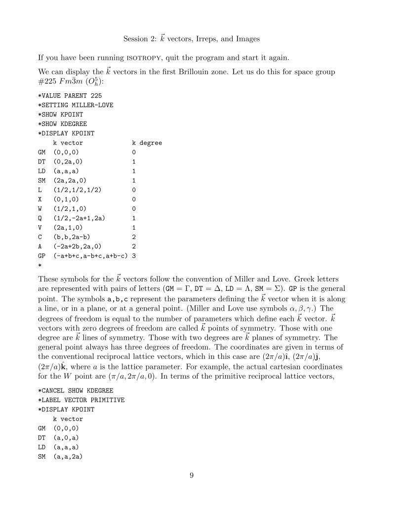
We can display the ~k vectors in the first Brillouin zone. Let us do this for space group#225 Fm3m (O5
h):
*VALUE PARENT 225
*SETTING MILLER-LOVE
*SHOW KPOINT
*SHOW KDEGREE
*DISPLAY KPOINT
k vector k degree
GM (0,0,0) 0
DT (0,2a,0) 1
LD (a,a,a) 1
SM (2a,2a,0) 1
L (1/2,1/2,1/2) 0
X (0,1,0) 0
W (1/2,1,0) 0
Q (1/2,-2a+1,2a) 1
V (2a,1,0) 1
C (b,b,2a-b) 2
A (-2a+2b,2a,0) 2
GP (-a+b+c,a-b+c,a+b-c) 3
*
These symbols for the ~k vectors follow the convention of Miller and Love. Greek lettersare represented with pairs of letters (GM = Γ, DT = ∆, LD = Λ, SM = Σ). GP is the general
point. The symbols a,b,c represent the parameters defining the ~k vector when it is alonga line, or in a plane, or at a general point. (Miller and Love use symbols α, β, γ.) The
degrees of freedom is equal to the number of parameters which define each ~k vector. ~kvectors with zero degrees of freedom are called ~k points of symmetry. Those with onedegree are ~k lines of symmetry. Those with two degrees are ~k planes of symmetry. Thegeneral point always has three degrees of freedom. The coordinates are given in terms ofthe conventional reciprocal lattice vectors, which in this case are (2π/a)ı, (2π/a),
(2π/a)k, where a is the lattice parameter. For example, the actual cartesian coordinatesfor the W point are (π/a, 2π/a, 0). In terms of the primitive reciprocal lattice vectors,
*CANCEL SHOW KDEGREE
*LABEL VECTOR PRIMITIVE
*DISPLAY KPOINT
k vector
GM (0,0,0)
DT (a,0,a)
LD (a,a,a)
SM (a,a,2a)
9

10 Session 2: k vectors, Irreps, and Images
L (1/2,1/2,1/2)
X (1/2,0,1/2)
W (1/2,1/4,3/4)
Q (1/2,a+1/4,-a+3/4)
V (1/2,a,a+1/2)
C (a,a,b)
A (a,-a+b,b)
GP (a,b,c)
*
We can select a particular ~k point and display its star:
*LABEL VECTOR CONVENTIONAL
*VALUE KPOINT X
*SHOW STAR
*DISPLAY KPOINT
k vector Star of k
X (0,1,0) (0,1,0), (1,0,0), (0,0,1)
*
Irreducible representations (irreps) are associated with ~k vectors. For example, the irrepsat the Γ point are
*CANCEL SHOW ALL
*VALUE KPOINT GM
*SHOW IRREP
*DISPLAY IRREP
Irrep (ML)
GM1+
GM2+
GM3+
GM4+
GM5+
GM1-
GM2-
GM3-
GM4-
GM5-
*
These irrep symbols following the convention of Miller and Love and denote the irrepsΓ+1 , Γ+
2 , etc. We can display the corresponding symbols for other settings:
*SHOW IRREP KOVALEV
*D IRREP
Irrep (ML) Irrep (Kov)
GM1+ k11t1
GM2+ k11t3
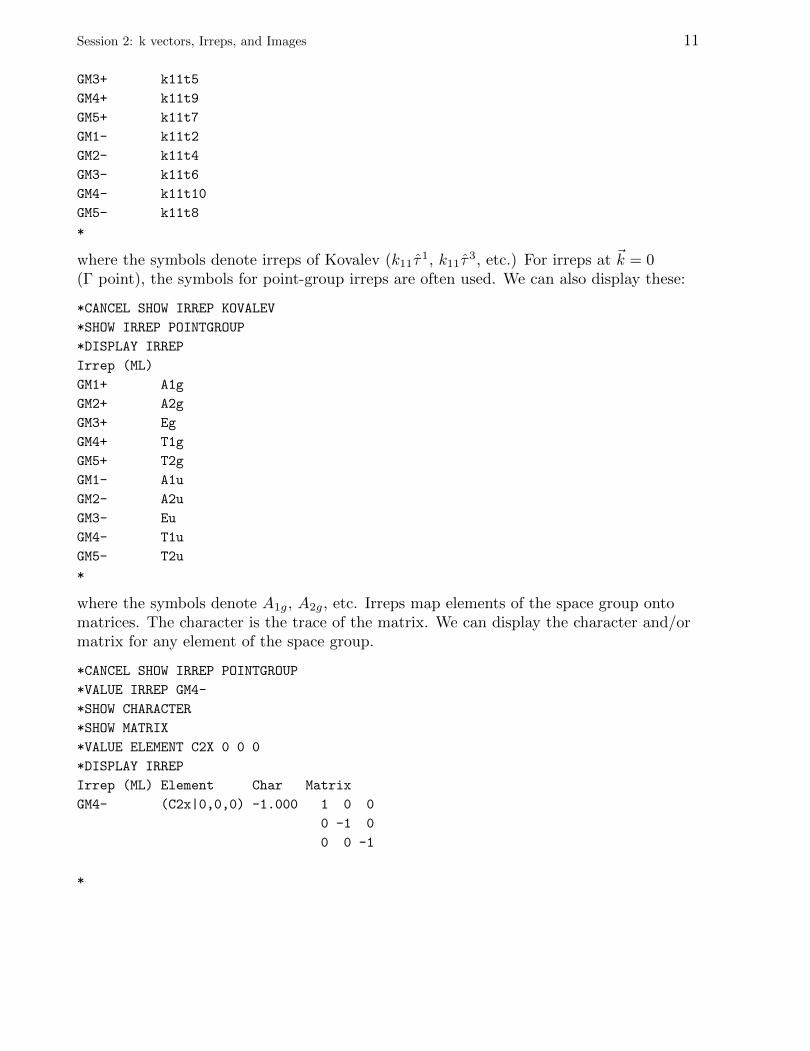
Session 2: k vectors, Irreps, and Images 11
GM3+ k11t5
GM4+ k11t9
GM5+ k11t7
GM1- k11t2
GM2- k11t4
GM3- k11t6
GM4- k11t10
GM5- k11t8
*
where the symbols denote irreps of Kovalev (k11τ1, k11τ
3, etc.) For irreps at ~k = 0(Γ point), the symbols for point-group irreps are often used. We can also display these:
*CANCEL SHOW IRREP KOVALEV
*SHOW IRREP POINTGROUP
*DISPLAY IRREP
Irrep (ML)
GM1+ A1g
GM2+ A2g
GM3+ Eg
GM4+ T1g
GM5+ T2g
GM1- A1u
GM2- A2u
GM3- Eu
GM4- T1u
GM5- T2u
*
where the symbols denote A1g, A2g, etc. Irreps map elements of the space group ontomatrices. The character is the trace of the matrix. We can display the character and/ormatrix for any element of the space group.
*CANCEL SHOW IRREP POINTGROUP
*VALUE IRREP GM4-
*SHOW CHARACTER
*SHOW MATRIX
*VALUE ELEMENT C2X 0 0 0
*DISPLAY IRREP
Irrep (ML) Element Char Matrix
GM4- (C2x|0,0,0) -1.000 1 0 0
0 -1 0
0 0 -1
*
12 Session 2: k vectors, Irreps, and Images
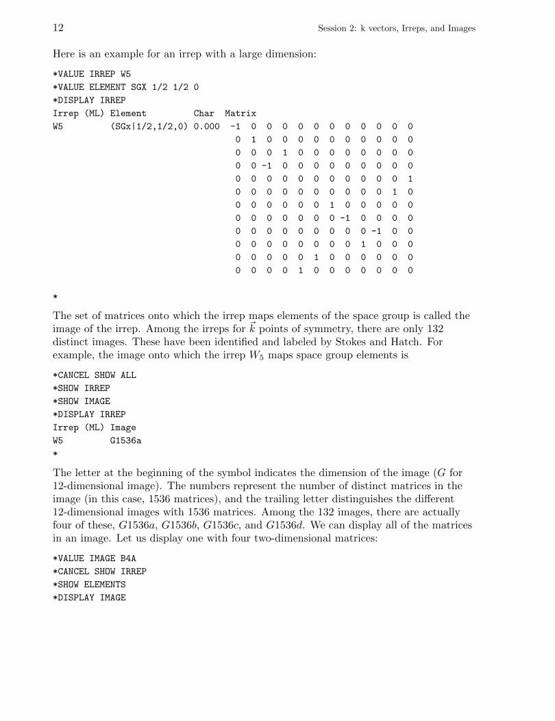
Here is an example for an irrep with a large dimension:
*VALUE IRREP W5
*VALUE ELEMENT SGX 1/2 1/2 0
*DISPLAY IRREP
Irrep (ML) Element Char Matrix
W5 (SGx|1/2,1/2,0) 0.000 -1 0 0 0 0 0 0 0 0 0 0 0
0 1 0 0 0 0 0 0 0 0 0 0
0 0 0 1 0 0 0 0 0 0 0 0
0 0 -1 0 0 0 0 0 0 0 0 0
0 0 0 0 0 0 0 0 0 0 0 1
0 0 0 0 0 0 0 0 0 0 1 0
0 0 0 0 0 0 1 0 0 0 0 0
0 0 0 0 0 0 0 -1 0 0 0 0
0 0 0 0 0 0 0 0 0 -1 0 0
0 0 0 0 0 0 0 0 1 0 0 0
0 0 0 0 0 1 0 0 0 0 0 0
0 0 0 0 1 0 0 0 0 0 0 0
*
The set of matrices onto which the irrep maps elements of the space group is called theimage of the irrep. Among the irreps for ~k points of symmetry, there are only 132distinct images. These have been identified and labeled by Stokes and Hatch. Forexample, the image onto which the irrep W5 maps space group elements is
*CANCEL SHOW ALL
*SHOW IRREP
*SHOW IMAGE
*DISPLAY IRREP
Irrep (ML) Image
W5 G1536a
*
The letter at the beginning of the symbol indicates the dimension of the image (G for12-dimensional image). The numbers represent the number of distinct matrices in theimage (in this case, 1536 matrices), and the trailing letter distinguishes the different12-dimensional images with 1536 matrices. Among the 132 images, there are actuallyfour of these, G1536a, G1536b, G1536c, and G1536d. We can display all of the matricesin an image. Let us display one with four two-dimensional matrices:
*VALUE IMAGE B4A
*CANCEL SHOW IRREP
*SHOW ELEMENTS
*DISPLAY IMAGE
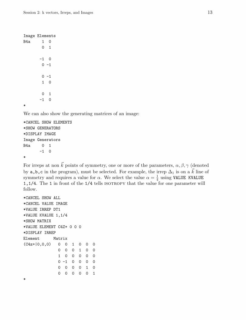
Session 2: k vectors, Irreps, and Images 13
Image Elements
B4a 1 0
0 1
-1 0
0 -1
0 -1
1 0
0 1
-1 0
*
We can also show the generating matrices of an image:
*CANCEL SHOW ELEMENTS
*SHOW GENERATORS
*DISPLAY IMAGE
Image Generators
B4a 0 1
-1 0
*
For irreps at non ~k points of symmetry, one or more of the parameters, α, β, γ (denoted
by a,b,c in the program), must be selected. For example, the irrep ∆1 is on a ~k line ofsymmetry and requires a value for α. We select the value α = 1
4 using VALUE KVALUE
1,1/4. The 1 in front of the 1/4 tells isotropy that the value for one parameter willfollow.
*CANCEL SHOW ALL
*CANCEL VALUE IMAGE
*VALUE IRREP DT1
*VALUE KVALUE 1,1/4
*SHOW MATRIX
*VALUE ELEMENT C4Z+ 0 0 0
*DISPLAY IRREP
Element Matrix
(C4z+|0,0,0) 0 0 1 0 0 0
0 0 0 1 0 0
1 0 0 0 0 0
0 -1 0 0 0 0
0 0 0 0 1 0
0 0 0 0 0 1
*
14 Session 2: k vectors, Irreps, and Images
Compatibility relations can also be shown. For example,
*CANCEL SHOW ALL
*VALUE KPOINT GM
*VALUE COMPATIBILITY DT
*SHOW COMPATIBILITY
*DISPLAY IRREP
Compat (ML)
GM1+: DT1
GM2+: DT2
GM3+: DT1 DT2
GM4+: DT4 DT5
GM5+: DT3 DT5
GM1-: DT4
GM2-: DT3
GM3-: DT3 DT4
GM4-: DT1 DT5
GM5-: DT2 DT5
*
These relations show what happens as the ~k vector moves along the ∆ line to the Γpoint: each ∆ irrep becomes a Γ representation which can be decomposed into one ormore Γ irreps. For example, the six-dimensional ∆1 irrep at the Γ point can bedecomposed into the one-dimensional Γ+
1 irrep, the two-dimensional Γ+3 irrep, and the
three-dimensional Γ4− irrep. These same relations show what happens to the irreps ofthe “little group of ~k” as the ~k vector moves from the Γ point along the ∆ line: each Γirrep of the little group becomes a ∆ representation of the little group which can bedecomposed into one or more ∆ irreps of the little group. For example, thethree-dimensional Γ−4 irrep of the little group splits into the one-dimensional ∆3 irrep ofthe little group and the two-dimensional ∆5 irrep of the little group. These compatibilityrelations are useful when labeling phonon dispersion curves and electron band structures.
Irreps are classified as type 1, type 2, and type 3. A type-1 irrep can be brought to realform by a similarity transformation. A type-2 irrep cannot be brought to real form, butit can be brought to its complex conjugate by a similarity transformation. A type-2 irrepis equivalent to its own complex conjugate. Its characters are real. A type-3 irrep cannotbe brought to real form and cannot be brought to its complex conjugate. Some of itscharacters are complex. In phase transformation theory, we use real matrices. For type-2and -3 irreps, we form real matrices by forming the direct sum of the matrix with itscomplex conjugate and then bringing the resulting matrix to real form by a similaritytransformation. This resulting reducible representation is said to be physicallyirreducible, i.e., irreducible with respect to real numbers. For example, there are threeirreps at the H point for space group #184: H1, H2 are type 3, and H3 is type 2. H2 isthe complex conjugate of H1, and H3 is equivalent to its own complex conjugate.
*VALUE PARENT 184
*VALUE KPOINT H

Session 2: k vectors, Irreps, and Images 15
*CANCEL SHOW ALL
*SHOW IRREP
*SHOW TYPE
*DISPLAY IRREP
Irrep (ML) Type
H1H2 3
H3H3 2
*
The program lists the physically irreducible representations, H1 ⊕H2 and H3 ⊕H3. Theprogram displays the matrices of these representations in real form:
*CANCEL VALUE KVALUE
*VALUE IRREP H1H2
*VALUE ELEMENT SGV1 0 0 1/2
*SHOW MATRIX
*DISPLAY IRREP
Irrep (ML) Type Element Matrix
H1H2 3 (SGv1|0,0,1/2) 0.000 0.000 0.500 0.866
0.000 0.000 0.866 -0.500
-0.500 -0.866 0.000 0.000
-0.866 0.500 0.000 0.000
*
This is the end of this tutorial. You may exit the program.
*QUIT

16
Session 3: Isotropy Subgroups
If you have been running isotropy, quit the program and start it again.
A great majority of solid-solid phase transitions can be described by the Landau theoryof phase transitions. In this theory, the free energy of a crystal is expanded in powers ofthe order parameter, an n-dimensional vector in representation space. A phase transitiontakes place when the minimum of the free energy occurs at a nonzero value of the orderparameter. Symmetry is lost in the transition, and the space-group symmetry is now asubgroup of the parent group and consists of all space-group elements which leave theorder parameter invariant. This is called an isotropy subgroup.As an example, let us consider the isotropy subgroups for the Γ−4 irrep of space group#221 Pm3m (O1
h).
*VALUE PARENT 221
*VALUE IRREP GM4-
*SHOW SUBGROUP
*SHOW BASIS
*SHOW ORIGIN
*DISPLAY ISOTROPY
Subgroup Basis Vectors Origin
99 P4mm (0,1,0),(0,0,1),(1,0,0) (0,0,0)
38 Amm2 (0,0,1),(1,-1,0),(1,1,0) (0,0,0)
160 R3m (1,-1,0),(0,1,-1),(1,1,1) (0,0,0)
6 Pm (0,1,0),(0,0,1),(1,0,0) (0,0,0)
8 Cm (1,1,0),(-1,1,0),(0,0,1) (0,0,0)
1 P1 (1,0,0),(0,1,0),(0,0,1) (0,0,0)
*
The coordinates of the origin as well as each basis vector of the lattice are given in termsof the basis vectors of the lattice of the parent space group. For example, the basisvectors ~a′i of the lattice of the isotropy subgroup R3m are given by
~a′1 = ~a1 − ~a2 ,
~a′2 = ~a2 − ~a3 ,
~a′3 = ~a1 + ~a2 + ~a3 ,
where ~ai are basis vectors of the lattice of the parent space group Pm3m. The irrep Γ−4is three dimensional so that in this case the order parameter is a three-dimensionalvector. We can display the direction of the order parameter for each isotropy subgroup:
*CANCEL SHOW BASIS
*CANCEL SHOW ORIGIN
*SHOW DIRECTION VECTOR
*DISPLAY ISOTROPY
17
18 Session 3: Isotropy Subgroups
Subgroup Dir
99 P4mm P1 (a,0,0)
38 Amm2 P2 (a,a,0)
160 R3m P3 (a,a,a)
6 Pm C1 (a,b,0)
8 Cm C2 (a,a,b)
1 P1 S1 (a,b,c)
*
The symbols, P3,P1,P3,C2,C1,S1, for the directions of the order parameters were chosenby Stokes and Hatch. The symbols, a,b,c, in the components of the order parametersrepresent arbitrary real numbers. Let us consider the isotropy subgroup P4mm. We canselect this subgroup with either the VALUE SUBGROUP 99 or the VALUE DIRECTION P1
command. Let us display the elements of the subgroup:
*VALUE DIRECTION P1
*SHOW ELEMENTS
*DISPLAY ISOTROPY
Subgroup Dir Elements
99 P4mm P1 (a,0,0) (E|0,0,0), (C2x|0,0,0), (C4x+|0,0,0), (C4x-|0,0,0),
(SGy|0,0,0), (SGz|0,0,0), (SGdf|0,0,0), (SGdd|0,0,0)
*
These are elements of the parent space group Pm3m which belong to the isotropysubgroup P4mm. We see that the four-fold rotation axis points in the cubic x direction,the same direction as the third basis vector of the lattice of P4mm (see above, where wedisplayed the basis vectors). In the setting of P4mm, these both become the z direction.
The irrep Γ−4 maps each element of the space group onto a three-dimensional matrix. Anelement operates on an order parameter via multiplication by these matrices. Theelements in the subgroup P4mm are mapped onto matrices which leave the orderparameter (a, 0, 0) invariant. For example, the matrix for {C+
4x|0, 0, 0} is
*SHOW MATRIX
*VALUE ELEMENT C4X+ 0 0 0
*DISPLAY IRREP
Element Matrix
(C4x+|0,0,0) 1 0 0
0 0 -1
0 1 0
*
Thus, when {C+4x|0, 0, 0} operates on (a, 0, 0), we obtain 1 0 0
0 0 −10 1 0
a00
=
a00
,
Session 3: Isotropy Subgroups 19
and, as we can see, the order parameter is left invariant by this operation. We can alsoshow the generating elements of the subgroup:
*CANCEL SHOW MATRIX
*CANCEL SHOW ELEMENT
*SHOW GENERATOR
*DISPLAY ISOTROPY
Subgroup Dir Generators
99 P4mm P1 (a,0,0) (C4x+|0,0,0), (SGy|0,0,0)
*
It is sometimes useful to obtain a mapping of points in the parent group to points in thesubgroup:
*CANCEL SHOW GENERATOR
*SHOW XYZ
*DISPLAY ISOTROPY
Subgroup Dir New xyz
99 P4mm P1 (a,0,0) (y,z,x)
*
This means that a point (x, y, z) in Pm3m becomes (y, z, x) in P4mm. For example, anatom at (0.681, 12 , 0) in Pm3m is at ( 1
2 , 0, 0.681) in P4mm. Perhaps an even more usefulfunction of isotropy is to identify the Wyckoff positions in the subgroup. For example,in Pm3m, an atom at (0.681, 12 , 0) is at Wyckoff position h (x, 12 , 0) with x = 0.681.
*CANCEL SHOW XYZ
*SHOW WYCKOFF SUBGROUP
*VALUE WYCKOFF H
*SHOW WYCKOFF VECTOR ALL
*DISPLAY PARENT
Wyckoff Points Coordinates
h (x,1/2,0), (-x,1/2,0), (1/2,0,x), (1/2,0,-x), (0,x,1/2),
(0,-x,-1/2), (-1/2,-x,0), (-1/2,x,0), (-x,0,-1/2), (x,0,1/2),
(0,-1/2,-x), (0,1/2,x)
*DISPLAY ISOTROPY
Subgroup Dir Wyckoff New Wyckoff
99 P4mm P1 (a,0,0) h c, z’=x
c, z’=-x
e, x’=-x, z’=1/2
f, x’=x, z’=0
*VALUE PARENT 99
*VALUE WYCKOFF C
*DISPLAY PARENT
Wyckoff Points Coordinates
c (1/2,0,z), (0,1/2,z)
*VALUE WYCKOFF E
20 Session 3: Isotropy Subgroups
*DISPLAY PARENT
Wyckoff Points Coordinates
e (x,0,z), (-x,0,z), (0,x,z), (0,-x,z)
*VALUE WYCKOFF F
*DISPLAY PARENT
Wyckoff Points Coordinates
f (x,1/2,z), (-x,-1/2,z), (-1/2,x,z), (1/2,-x,z)
*VALUE PARENT 221
*
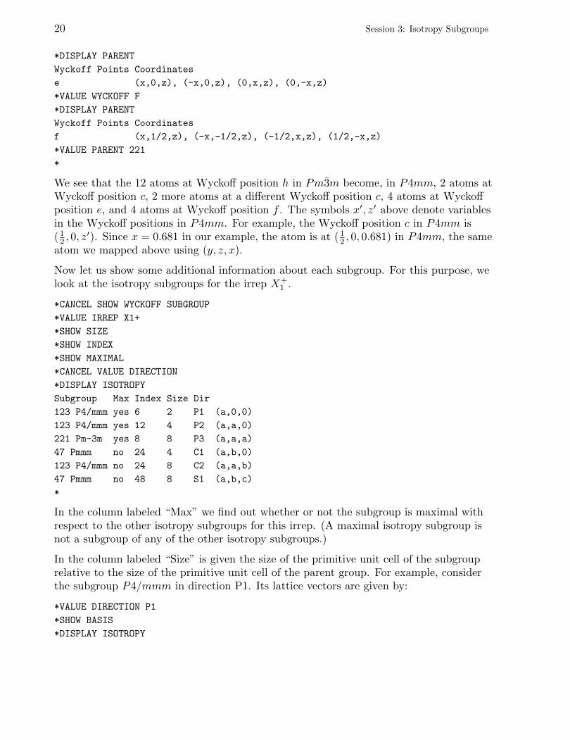
We see that the 12 atoms at Wyckoff position h in Pm3m become, in P4mm, 2 atoms atWyckoff position c, 2 more atoms at a different Wyckoff position c, 4 atoms at Wyckoffposition e, and 4 atoms at Wyckoff position f . The symbols x′, z′ above denote variablesin the Wyckoff positions in P4mm. For example, the Wyckoff position c in P4mm is( 12 , 0, z
′). Since x = 0.681 in our example, the atom is at ( 12 , 0, 0.681) in P4mm, the same
atom we mapped above using (y, z, x).
Now let us show some additional information about each subgroup. For this purpose, welook at the isotropy subgroups for the irrep X+
1 .
*CANCEL SHOW WYCKOFF SUBGROUP
*VALUE IRREP X1+
*SHOW SIZE
*SHOW INDEX
*SHOW MAXIMAL
*CANCEL VALUE DIRECTION
*DISPLAY ISOTROPY
Subgroup Max Index Size Dir
123 P4/mmm yes 6 2 P1 (a,0,0)
123 P4/mmm yes 12 4 P2 (a,a,0)
221 Pm-3m yes 8 8 P3 (a,a,a)
47 Pmmm no 24 4 C1 (a,b,0)
123 P4/mmm no 24 8 C2 (a,a,b)
47 Pmmm no 48 8 S1 (a,b,c)
*
In the column labeled “Max” we find out whether or not the subgroup is maximal withrespect to the other isotropy subgroups for this irrep. (A maximal isotropy subgroup isnot a subgroup of any of the other isotropy subgroups.)
In the column labeled “Size” is given the size of the primitive unit cell of the subgrouprelative to the size of the primitive unit cell of the parent group. For example, considerthe subgroup P4/mmm in direction P1. Its lattice vectors are given by:
*VALUE DIRECTION P1
*SHOW BASIS
*DISPLAY ISOTROPY
Session 3: Isotropy Subgroups 21
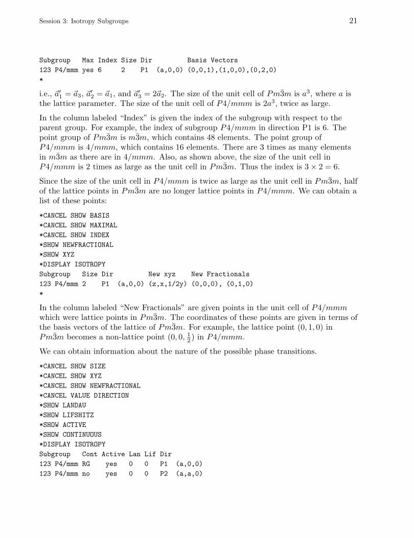
Subgroup Max Index Size Dir Basis Vectors
123 P4/mmm yes 6 2 P1 (a,0,0) (0,0,1),(1,0,0),(0,2,0)
*
i.e., ~a′1 = ~a3, ~a′2 = ~a1, and ~a′3 = 2~a2. The size of the unit cell of Pm3m is a3, where a isthe lattice parameter. The size of the unit cell of P4/mmm is 2a3, twice as large.
In the column labeled “Index” is given the index of the subgroup with respect to theparent group. For example, the index of subgroup P4/mmm in direction P1 is 6. Thepoint group of Pm3m is m3m, which contains 48 elements. The point group ofP4/mmm is 4/mmm, which contains 16 elements. There are 3 times as many elementsin m3m as there are in 4/mmm. Also, as shown above, the size of the unit cell inP4/mmm is 2 times as large as the unit cell in Pm3m. Thus the index is 3× 2 = 6.
Since the size of the unit cell in P4/mmm is twice as large as the unit cell in Pm3m, halfof the lattice points in Pm3m are no longer lattice points in P4/mmm. We can obtain alist of these points:
*CANCEL SHOW BASIS
*CANCEL SHOW MAXIMAL
*CANCEL SHOW INDEX
*SHOW NEWFRACTIONAL
*SHOW XYZ
*DISPLAY ISOTROPY
Subgroup Size Dir New xyz New Fractionals
123 P4/mmm 2 P1 (a,0,0) (z,x,1/2y) (0,0,0), (0,1,0)
*
In the column labeled “New Fractionals” are given points in the unit cell of P4/mmmwhich were lattice points in Pm3m. The coordinates of these points are given in terms ofthe basis vectors of the lattice of Pm3m. For example, the lattice point (0, 1, 0) inPm3m becomes a non-lattice point (0, 0, 12 ) in P4/mmm.
We can obtain information about the nature of the possible phase transitions.
*CANCEL SHOW SIZE
*CANCEL SHOW XYZ
*CANCEL SHOW NEWFRACTIONAL
*CANCEL VALUE DIRECTION
*SHOW LANDAU
*SHOW LIFSHITZ
*SHOW ACTIVE
*SHOW CONTINUOUS
*DISPLAY ISOTROPY
Subgroup Cont Active Lan Lif Dir
123 P4/mmm RG yes 0 0 P1 (a,0,0)
123 P4/mmm no yes 0 0 P2 (a,a,0)
22 Session 3: Isotropy Subgroups
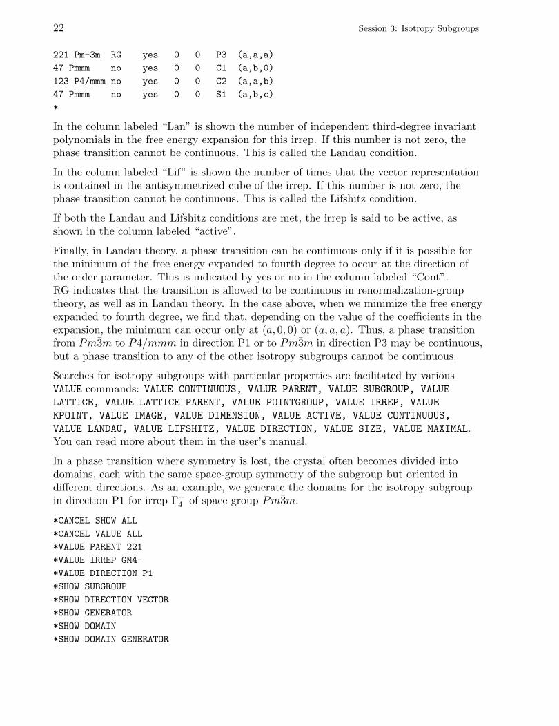
221 Pm-3m RG yes 0 0 P3 (a,a,a)
47 Pmmm no yes 0 0 C1 (a,b,0)
123 P4/mmm no yes 0 0 C2 (a,a,b)
47 Pmmm no yes 0 0 S1 (a,b,c)
*
In the column labeled “Lan” is shown the number of independent third-degree invariantpolynomials in the free energy expansion for this irrep. If this number is not zero, thephase transition cannot be continuous. This is called the Landau condition.
In the column labeled “Lif” is shown the number of times that the vector representationis contained in the antisymmetrized cube of the irrep. If this number is not zero, thephase transition cannot be continuous. This is called the Lifshitz condition.
If both the Landau and Lifshitz conditions are met, the irrep is said to be active, asshown in the column labeled “active”.
Finally, in Landau theory, a phase transition can be continuous only if it is possible forthe minimum of the free energy expanded to fourth degree to occur at the direction ofthe order parameter. This is indicated by yes or no in the column labeled “Cont”.RG indicates that the transition is allowed to be continuous in renormalization-grouptheory, as well as in Landau theory. In the case above, when we minimize the free energyexpanded to fourth degree, we find that, depending on the value of the coefficients in theexpansion, the minimum can occur only at (a, 0, 0) or (a, a, a). Thus, a phase transitionfrom Pm3m to P4/mmm in direction P1 or to Pm3m in direction P3 may be continuous,but a phase transition to any of the other isotropy subgroups cannot be continuous.
Searches for isotropy subgroups with particular properties are facilitated by variousVALUE commands: VALUE CONTINUOUS, VALUE PARENT, VALUE SUBGROUP, VALUE
LATTICE, VALUE LATTICE PARENT, VALUE POINTGROUP, VALUE IRREP, VALUE
KPOINT, VALUE IMAGE, VALUE DIMENSION, VALUE ACTIVE, VALUE CONTINUOUS,
VALUE LANDAU, VALUE LIFSHITZ, VALUE DIRECTION, VALUE SIZE, VALUE MAXIMAL.You can read more about them in the user’s manual.
In a phase transition where symmetry is lost, the crystal often becomes divided intodomains, each with the same space-group symmetry of the subgroup but oriented indifferent directions. As an example, we generate the domains for the isotropy subgroupin direction P1 for irrep Γ−4 of space group Pm3m.
*CANCEL SHOW ALL
*CANCEL VALUE ALL
*VALUE PARENT 221
*VALUE IRREP GM4-
*VALUE DIRECTION P1
*SHOW SUBGROUP
*SHOW DIRECTION VECTOR
*SHOW GENERATOR
*SHOW DOMAIN
*SHOW DOMAIN GENERATOR
Session 3: Isotropy Subgroups 23
*SHOW DISTINCT
*DISPLAY ISOTROPY
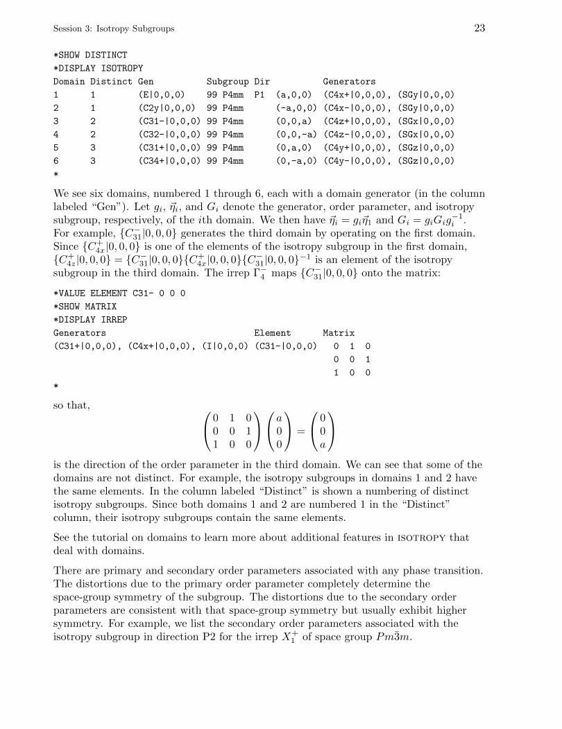
Domain Distinct Gen Subgroup Dir Generators
1 1 (E|0,0,0) 99 P4mm P1 (a,0,0) (C4x+|0,0,0), (SGy|0,0,0)
2 1 (C2y|0,0,0) 99 P4mm (-a,0,0) (C4x-|0,0,0), (SGy|0,0,0)
3 2 (C31-|0,0,0) 99 P4mm (0,0,a) (C4z+|0,0,0), (SGx|0,0,0)
4 2 (C32-|0,0,0) 99 P4mm (0,0,-a) (C4z-|0,0,0), (SGx|0,0,0)
5 3 (C31+|0,0,0) 99 P4mm (0,a,0) (C4y+|0,0,0), (SGz|0,0,0)
6 3 (C34+|0,0,0) 99 P4mm (0,-a,0) (C4y-|0,0,0), (SGz|0,0,0)
*
We see six domains, numbered 1 through 6, each with a domain generator (in the columnlabeled “Gen”). Let gi, ~ηi, and Gi denote the generator, order parameter, and isotropysubgroup, respectively, of the ith domain. We then have ~ηi = gi~η1 and Gi = giGig
−1i .
For example, {C−31|0, 0, 0} generates the third domain by operating on the first domain.Since {C+
4x|0, 0, 0} is one of the elements of the isotropy subgroup in the first domain,{C+
4z|0, 0, 0} = {C−31|0, 0, 0}{C+4x|0, 0, 0}{C
−31|0, 0, 0}−1 is an element of the isotropy
subgroup in the third domain. The irrep Γ−4 maps {C−31|0, 0, 0} onto the matrix:
*VALUE ELEMENT C31- 0 0 0
*SHOW MATRIX
*DISPLAY IRREP
Generators Element Matrix
(C31+|0,0,0), (C4x+|0,0,0), (I|0,0,0) (C31-|0,0,0) 0 1 0
0 0 1
1 0 0
*
so that, 0 1 00 0 11 0 0
a00
=
00a
is the direction of the order parameter in the third domain. We can see that some of thedomains are not distinct. For example, the isotropy subgroups in domains 1 and 2 havethe same elements. In the column labeled “Distinct” is shown a numbering of distinctisotropy subgroups. Since both domains 1 and 2 are numbered 1 in the “Distinct”column, their isotropy subgroups contain the same elements.
See the tutorial on domains to learn more about additional features in isotropy thatdeal with domains.
There are primary and secondary order parameters associated with any phase transition.The distortions due to the primary order parameter completely determine thespace-group symmetry of the subgroup. The distortions due to the secondary orderparameters are consistent with that space-group symmetry but usually exhibit highersymmetry. For example, we list the secondary order parameters associated with theisotropy subgroup in direction P2 for the irrep X+
1 of space group Pm3m.
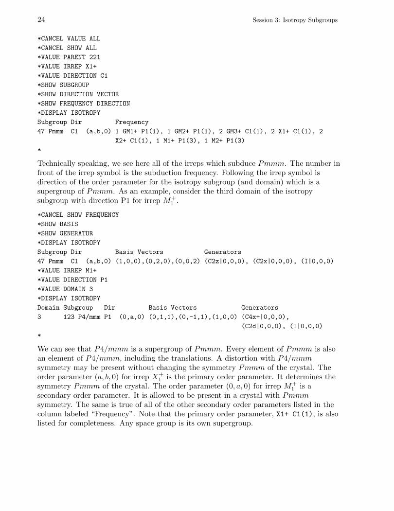
24 Session 3: Isotropy Subgroups
*CANCEL VALUE ALL
*CANCEL SHOW ALL
*VALUE PARENT 221
*VALUE IRREP X1+
*VALUE DIRECTION C1
*SHOW SUBGROUP
*SHOW DIRECTION VECTOR
*SHOW FREQUENCY DIRECTION
*DISPLAY ISOTROPY
Subgroup Dir Frequency
47 Pmmm C1 (a,b,0) 1 GM1+ P1(1), 1 GM2+ P1(1), 2 GM3+ C1(1), 2 X1+ C1(1), 2
X2+ C1(1), 1 M1+ P1(3), 1 M2+ P1(3)
*
Technically speaking, we see here all of the irreps which subduce Pmmm. The number infront of the irrep symbol is the subduction frequency. Following the irrep symbol isdirection of the order parameter for the isotropy subgroup (and domain) which is asupergroup of Pmmm. As an example, consider the third domain of the isotropysubgroup with direction P1 for irrep M+
1 .
*CANCEL SHOW FREQUENCY
*SHOW BASIS
*SHOW GENERATOR
*DISPLAY ISOTROPY
Subgroup Dir Basis Vectors Generators
47 Pmmm C1 (a,b,0) (1,0,0),(0,2,0),(0,0,2) (C2z|0,0,0), (C2x|0,0,0), (I|0,0,0)
*VALUE IRREP M1+
*VALUE DIRECTION P1
*VALUE DOMAIN 3
*DISPLAY ISOTROPY
Domain Subgroup Dir Basis Vectors Generators
3 123 P4/mmm P1 (0,a,0) (0,1,1),(0,-1,1),(1,0,0) (C4x+|0,0,0),
(C2d|0,0,0), (I|0,0,0)
*
We can see that P4/mmm is a supergroup of Pmmm. Every element of Pmmm is alsoan element of P4/mmm, including the translations. A distortion with P4/mmmsymmetry may be present without changing the symmetry Pmmm of the crystal. Theorder parameter (a, b, 0) for irrep X+
1 is the primary order parameter. It determines thesymmetry Pmmm of the crystal. The order parameter (0, a, 0) for irrep M+
1 is asecondary order parameter. It is allowed to be present in a crystal with Pmmmsymmetry. The same is true of all of the other secondary order parameters listed in thecolumn labeled “Frequency”. Note that the primary order parameter, X1+ C1(1), is alsolisted for completeness. Any space group is its own supergroup.
Session 3: Isotropy Subgroups 25
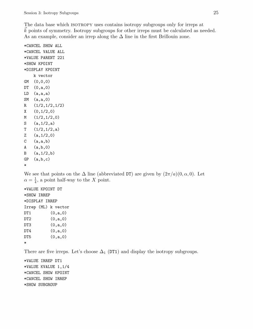
The data base which isotropy uses contains isotropy subgroups only for irreps at~k points of symmetry. Isotropy subgroups for other irreps must be calculated as needed.As an example, consider an irrep along the ∆ line in the first Brillouin zone.
*CANCEL SHOW ALL
*CANCEL VALUE ALL
*VALUE PARENT 221
*SHOW KPOINT
*DISPLAY KPOINT
k vector
GM (0,0,0)
DT (0,a,0)
LD (a,a,a)
SM (a,a,0)
R (1/2,1/2,1/2)
X (0,1/2,0)
M (1/2,1/2,0)
S (a,1/2,a)
T (1/2,1/2,a)
Z (a,1/2,0)
C (a,a,b)
A (a,b,0)
B (a,1/2,b)
GP (a,b,c)
*
We see that points on the ∆ line (abbreviated DT) are given by (2π/a)(0, α, 0). Letα = 1
4 , a point half-way to the X point.
*VALUE KPOINT DT
*SHOW IRREP
*DISPLAY IRREP
Irrep (ML) k vector
DT1 (0,a,0)
DT2 (0,a,0)
DT3 (0,a,0)
DT4 (0,a,0)
DT5 (0,a,0)
*
There are five irreps. Let’s choose ∆1 (DT1) and display the isotropy subgroups.
*VALUE IRREP DT1
*VALUE KVALUE 1,1/4
*CANCEL SHOW KPOINT
*CANCEL SHOW IRREP
*SHOW SUBGROUP
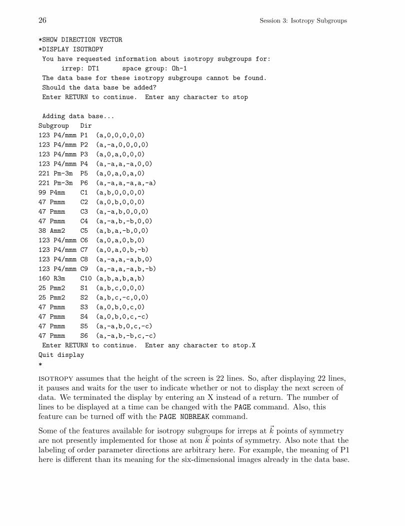
26 Session 3: Isotropy Subgroups
*SHOW DIRECTION VECTOR
*DISPLAY ISOTROPY
You have requested information about isotropy subgroups for:
irrep: DT1 space group: Oh-1
The data base for these isotropy subgroups cannot be found.
Should the data base be added?
Enter RETURN to continue. Enter any character to stop
Adding data base...
Subgroup Dir
123 P4/mmm P1 (a,0,0,0,0,0)
123 P4/mmm P2 (a,-a,0,0,0,0)
123 P4/mmm P3 (a,0,a,0,0,0)
123 P4/mmm P4 (a,-a,a,-a,0,0)
221 Pm-3m P5 (a,0,a,0,a,0)
221 Pm-3m P6 (a,-a,a,-a,a,-a)
99 P4mm C1 (a,b,0,0,0,0)
47 Pmmm C2 (a,0,b,0,0,0)
47 Pmmm C3 (a,-a,b,0,0,0)
47 Pmmm C4 (a,-a,b,-b,0,0)
38 Amm2 C5 (a,b,a,-b,0,0)
123 P4/mmm C6 (a,0,a,0,b,0)
123 P4/mmm C7 (a,0,a,0,b,-b)
123 P4/mmm C8 (a,-a,a,-a,b,0)
123 P4/mmm C9 (a,-a,a,-a,b,-b)
160 R3m C10 (a,b,a,b,a,b)
25 Pmm2 S1 (a,b,c,0,0,0)
25 Pmm2 S2 (a,b,c,-c,0,0)
47 Pmmm S3 (a,0,b,0,c,0)
47 Pmmm S4 (a,0,b,0,c,-c)
47 Pmmm S5 (a,-a,b,0,c,-c)
47 Pmmm S6 (a,-a,b,-b,c,-c)
Enter RETURN to continue. Enter any character to stop.X
Quit display
*
isotropy assumes that the height of the screen is 22 lines. So, after displaying 22 lines,it pauses and waits for the user to indicate whether or not to display the next screen ofdata. We terminated the display by entering an X instead of a return. The number oflines to be displayed at a time can be changed with the PAGE command. Also, thisfeature can be turned off with the PAGE NOBREAK command.
Some of the features available for isotropy subgroups for irreps at ~k points of symmetryare not presently implemented for those at non ~k points of symmetry. Also note that thelabeling of order parameter directions are arbitrary here. For example, the meaning of P1here is different than its meaning for the six-dimensional images already in the data base.
Session 3: Isotropy Subgroups 27
The labels for the directions are merely given for convenience so that we can refer to aparticular isotropy subgroup using it.
*VALUE DIRECTION P6
*DISPLAY ISOTROPY
Subgroup Dir
221 Pm-3m P6 (a,-a,a,-a,a,-a)
*
Sometimes, the list of isotropy subgroups for a particular irrep may be very long andmay require an unreasonable amount of time for isotropy to calculate them. A shorterlist can be generated by using only one arm of the star. You can do that by using VALUE
DIRECTION ONEARM. Sometimes only the kernel is needed. (The kernel is the isotropysubgroup for a general direction of the order parameter.) This can be generated usingVALUE DIRECTION KERNEL.
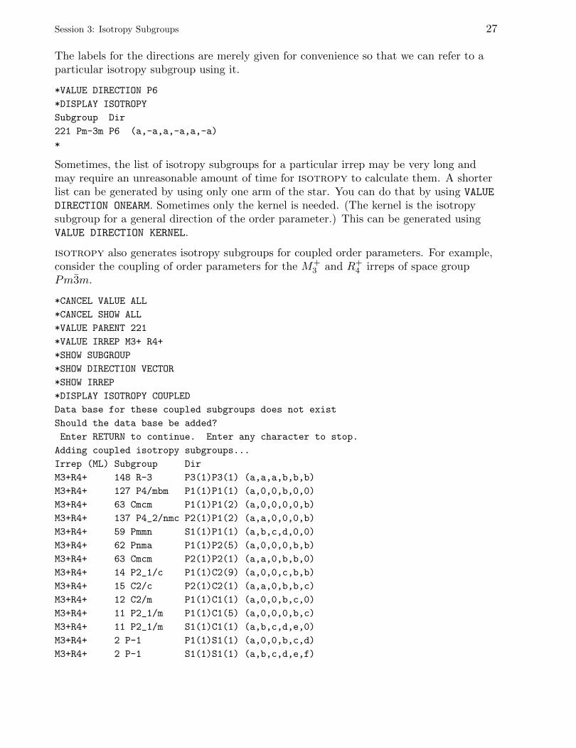
isotropy also generates isotropy subgroups for coupled order parameters. For example,consider the coupling of order parameters for the M+
3 and R+4 irreps of space group
Pm3m.
*CANCEL VALUE ALL
*CANCEL SHOW ALL
*VALUE PARENT 221
*VALUE IRREP M3+ R4+
*SHOW SUBGROUP
*SHOW DIRECTION VECTOR
*SHOW IRREP
*DISPLAY ISOTROPY COUPLED
Data base for these coupled subgroups does not exist
Should the data base be added?
Enter RETURN to continue. Enter any character to stop.
Adding coupled isotropy subgroups...
Irrep (ML) Subgroup Dir
M3+R4+ 148 R-3 P3(1)P3(1) (a,a,a,b,b,b)
M3+R4+ 127 P4/mbm P1(1)P1(1) (a,0,0,b,0,0)
M3+R4+ 63 Cmcm P1(1)P1(2) (a,0,0,0,0,b)
M3+R4+ 137 P4_2/nmc P2(1)P1(2) (a,a,0,0,0,b)
M3+R4+ 59 Pmmn S1(1)P1(1) (a,b,c,d,0,0)
M3+R4+ 62 Pnma P1(1)P2(5) (a,0,0,0,b,b)
M3+R4+ 63 Cmcm P2(1)P2(1) (a,a,0,b,b,0)
M3+R4+ 14 P2_1/c P1(1)C2(9) (a,0,0,c,b,b)
M3+R4+ 15 C2/c P2(1)C2(1) (a,a,0,b,b,c)
M3+R4+ 12 C2/m P1(1)C1(1) (a,0,0,b,c,0)
M3+R4+ 11 P2_1/m P1(1)C1(5) (a,0,0,0,b,c)
M3+R4+ 11 P2_1/m S1(1)C1(1) (a,b,c,d,e,0)
M3+R4+ 2 P-1 P1(1)S1(1) (a,0,0,b,c,d)
M3+R4+ 2 P-1 S1(1)S1(1) (a,b,c,d,e,f)

28 Session 3: Isotropy Subgroups
*
isotropy generates a file containing information about these isotropy subgroups. In thiscase, the file was named s4550_01.iso. In the future, when we ask about thesesubgroups, isotropy will find this file and will not need to generate the data again.
These isotropy subgroups actually belong to the six-dimensional reducible representationM+
3 ⊕R+4 , the direct sum of M+
3 and R+4 . The first three components of the order
parameter belong to M+3 and the last three components belong to R+
4 . For example, thefirst subgroup in the list contains all of the elements that keep the direction (a, a, a) ofthe order parameter for M+
3 invariant, and, at the same time, keep the direction (b, b, b)of the order parameter for R+
4 invariant. It is actually the intersection of the isotropysubgroup in direction P3 for M+
3 and the isotropy subgroup in direction P3 for R+4 . That
is the meaning of the symbol for the direction: P3(1)P3(1). The numbers in parenthesesrefer to domains. In this case, the two isotropy subgroups are those of the first domain.The third subgroup in the list, however, is an intersection of the first domain (a, 0, 0) ofthe isotropy subgroup in direction P1 for M+
3 and the second domain (0, 0, b) of theisotropy subgroup in direction P1 for R+
4 . We can select one of these isotropy subgroupsusing the symbol for the direction of the order parameter exactly as it appears in the list.
*VALUE DIRECTION P1(1)P1(2)
*DISPLAY ISOTROPY COUPLED
Irrep (ML) Subgroup Dir
M3+R4+ 63 Cmcm P1(1)P1(2) (a,0,0,0,0,b)
*
What do you do if you know the structure of the subgroup but do not know which irrepdrives the transition? isotropy has a very useful feature for finding the primary andsecondary order parameters if the group-subgroup relation is known.
As an example, consider a monoclinic subgroup of Pm3m. Suppose that we know itsspace-group symmetry is P2/m, the basis vectors of its lattice is (1, 1, 1), (1, 1, 0),(0, 0, 1), and its origin is at the same point as the origin of the parent group Pm3m.
*VALUE SUBGROUP 10
*VALUE BASIS 1,-1,1 1,1,0 0,0,1
*VALUE ORIGIN 0,0,0
*SHOW KPOINT
*DISPLAY DIRECTION
Irrep (ML) k vector Dir Subgroup Size
GM1+ (0,0,0) (a) 221 Pm-3m 1
GM3+ (0,0,0) (a,0) 123 P4/mmm 1
GM4+ (0,0,0) (a,a,0) 12 C2/m 1
GM5+ (0,0,0) (a,b,-b) 12 C2/m 1
M1+ (1/2,1/2,0) (a,0,0) 123 P4/mmm 2
M4+ (1/2,1/2,0) (a,0,0) 123 P4/mmm 2
M5+ (1/2,1/2,0) (a,a,0,0,-a,a) 53 Pmna 2
Session 3: Isotropy Subgroups 29
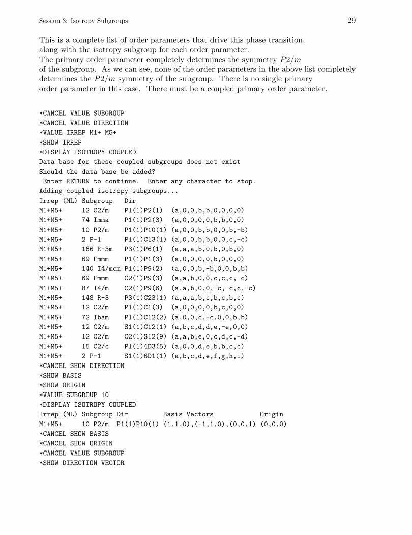
This is a complete list of order parameters that drive this phase transition,along with the isotropy subgroup for each order parameter.The primary order parameter completely determines the symmetry P2/mof the subgroup. As we can see, none of the order parameters in the above list completelydetermines the P2/m symmetry of the subgroup. There is no single primaryorder parameter in this case. There must be a coupled primary order parameter.
*CANCEL VALUE SUBGROUP
*CANCEL VALUE DIRECTION
*VALUE IRREP M1+ M5+
*SHOW IRREP
*DISPLAY ISOTROPY COUPLED
Data base for these coupled subgroups does not exist
Should the data base be added?
Enter RETURN to continue. Enter any character to stop.
Adding coupled isotropy subgroups...
Irrep (ML) Subgroup Dir
M1+M5+ 12 C2/m P1(1)P2(1) (a,0,0,b,b,0,0,0,0)
M1+M5+ 74 Imma P1(1)P2(3) (a,0,0,0,0,b,b,0,0)
M1+M5+ 10 P2/m P1(1)P10(1) (a,0,0,b,b,0,0,b,-b)
M1+M5+ 2 P-1 P1(1)C13(1) (a,0,0,b,b,0,0,c,-c)
M1+M5+ 166 R-3m P3(1)P6(1) (a,a,a,b,0,b,0,b,0)
M1+M5+ 69 Fmmm P1(1)P1(3) (a,0,0,0,0,b,0,0,0)
M1+M5+ 140 I4/mcm P1(1)P9(2) (a,0,0,b,-b,0,0,b,b)
M1+M5+ 69 Fmmm C2(1)P9(3) (a,a,b,0,0,c,c,c,-c)
M1+M5+ 87 I4/m C2(1)P9(6) (a,a,b,0,0,-c,-c,c,-c)
M1+M5+ 148 R-3 P3(1)C23(1) (a,a,a,b,c,b,c,b,c)
M1+M5+ 12 C2/m P1(1)C1(3) (a,0,0,0,0,b,c,0,0)
M1+M5+ 72 Ibam P1(1)C12(2) (a,0,0,c,-c,0,0,b,b)
M1+M5+ 12 C2/m S1(1)C12(1) (a,b,c,d,d,e,-e,0,0)
M1+M5+ 12 C2/m C2(1)S12(9) (a,a,b,e,0,c,d,c,-d)
M1+M5+ 15 C2/c P1(1)4D3(5) (a,0,0,d,e,b,b,c,c)
M1+M5+ 2 P-1 S1(1)6D1(1) (a,b,c,d,e,f,g,h,i)
*CANCEL SHOW DIRECTION
*SHOW BASIS
*SHOW ORIGIN
*VALUE SUBGROUP 10
*DISPLAY ISOTROPY COUPLED
Irrep (ML) Subgroup Dir Basis Vectors Origin
M1+M5+ 10 P2/m P1(1)P10(1) (1,1,0),(-1,1,0),(0,0,1) (0,0,0)
*CANCEL SHOW BASIS
*CANCEL SHOW ORIGIN
*CANCEL VALUE SUBGROUP
*SHOW DIRECTION VECTOR

30 Session 3: Isotropy Subgroups
*VALUE IRREP M4+ M5+
*DISPLAY ISOTROPY COUPLED
Data base for these coupled subgroups does not exist
Should the data base be added?
Enter RETURN to continue. Enter any character to stop.
Adding coupled isotropy subgroups...
Irrep (ML) Subgroup Dir
M4+M5+ 12 C2/m P1(1)P2(1) (a,0,0,b,b,0,0,0,0)
M4+M5+ 74 Imma P1(1)P2(2) (a,0,0,0,0,0,0,b,b)
M4+M5+ 10 P2/m P1(1)P10(1) (a,0,0,b,b,0,0,b,-b)
M4+M5+ 2 P-1 P1(1)C13(1) (a,0,0,b,b,0,0,c,-c)
M4+M5+ 166 R-3m P3(1)P6(1) (a,a,a,b,0,b,0,b,0)
M4+M5+ 140 I4/mcm P1(1)P1(3) (a,0,0,0,0,b,0,0,0)
M4+M5+ 69 Fmmm C2(1)P1(1) (a,a,b,c,0,0,0,0,0)
M4+M5+ 87 I4/m C2(1)P1(4) (a,a,b,0,c,0,0,0,0)
M4+M5+ 69 Fmmm P1(1)P9(2) (a,0,0,b,-b,0,0,b,b)
M4+M5+ 148 R-3 P3(1)C23(1) (a,a,a,b,c,b,c,b,c)
M4+M5+ 72 Ibam P1(1)C1(3) (a,0,0,0,0,b,c,0,0)
M4+M5+ 12 C2/m S1(1)C1(1) (a,b,c,d,e,0,0,0,0)
M4+M5+ 12 C2/m P1(1)C12(2) (a,0,0,c,-c,0,0,b,b)
M4+M5+ 12 C2/m C2(1)S12(9) (a,a,b,e,0,c,d,c,-d)
M4+M5+ 15 C2/c P1(1)4D3(3) (a,0,0,c,c,d,e,b,b)
M4+M5+ 2 P-1 S1(1)6D1(1) (a,b,c,d,e,f,g,h,i)
*CANCEL SHOW DIRECTION
*SHOW BASIS
*SHOW ORIGIN
*VALUE SUBGROUP 10
*DISPLAY ISOTROPY COUPLED
Irrep (ML) Subgroup Basis Vectors Origin
M4+M5+ 10 P2/m (1,1,0),(-1,1,0),(0,0,1) (0,0,0)
*
We see that M+5 may couple with either M+
1 or M+4 to produce the P2/m symmetry.
This result would have been rather difficult to obtain without this very useful DISPLAYDIRECTION feature of isotropy.
This is the end of this tutorial. You may exit the program.
*QUIT
Session 4: Distortions
If you have been running isotropy, quit the program and start it again.
There are two different kinds of distortions in a crystal: macroscopic and microscopic.Macroscopic distortions are tensor quantities like strain which involve the crystal as awhole. Microscopic distortions involve individual atoms. They include atomicdisplacements and molecular rotations.
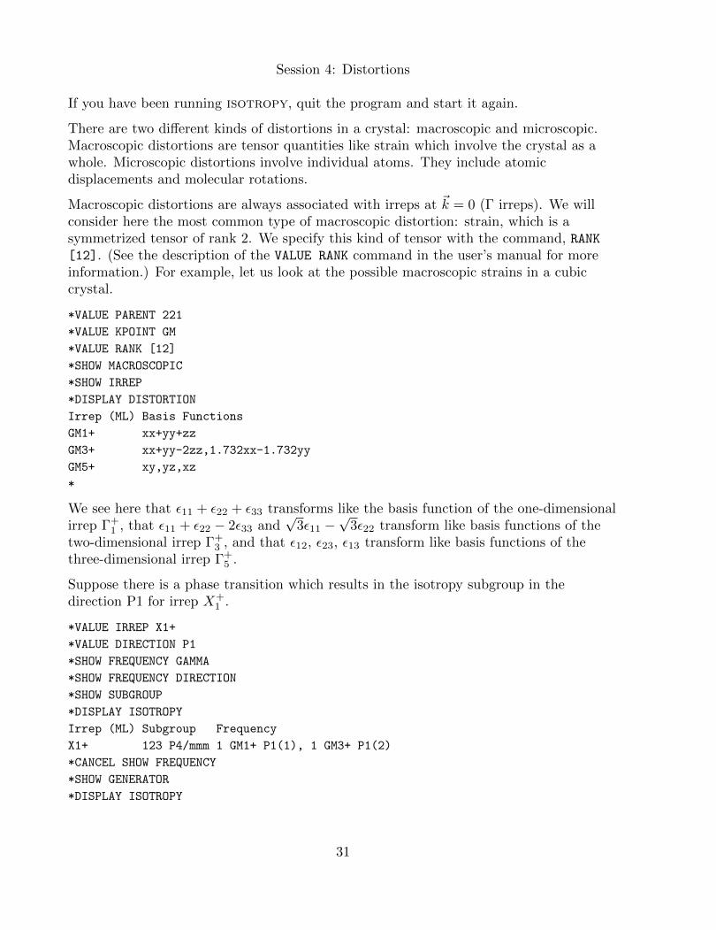
Macroscopic distortions are always associated with irreps at ~k = 0 (Γ irreps). We willconsider here the most common type of macroscopic distortion: strain, which is asymmetrized tensor of rank 2. We specify this kind of tensor with the command, RANK[12]. (See the description of the VALUE RANK command in the user’s manual for moreinformation.) For example, let us look at the possible macroscopic strains in a cubiccrystal.
*VALUE PARENT 221
*VALUE KPOINT GM
*VALUE RANK [12]
*SHOW MACROSCOPIC
*SHOW IRREP
*DISPLAY DISTORTION
Irrep (ML) Basis Functions
GM1+ xx+yy+zz
GM3+ xx+yy-2zz,1.732xx-1.732yy
GM5+ xy,yz,xz
*
We see here that ε11 + ε22 + ε33 transforms like the basis function of the one-dimensionalirrep Γ+
1 , that ε11 + ε22 − 2ε33 and√
3ε11 −√
3ε22 transform like basis functions of thetwo-dimensional irrep Γ+
3 , and that ε12, ε23, ε13 transform like basis functions of thethree-dimensional irrep Γ+
5 .
Suppose there is a phase transition which results in the isotropy subgroup in thedirection P1 for irrep X+
1 .
*VALUE IRREP X1+
*VALUE DIRECTION P1
*SHOW FREQUENCY GAMMA
*SHOW FREQUENCY DIRECTION
*SHOW SUBGROUP
*DISPLAY ISOTROPY
Irrep (ML) Subgroup Frequency
X1+ 123 P4/mmm 1 GM1+ P1(1), 1 GM3+ P1(2)
*CANCEL SHOW FREQUENCY
*SHOW GENERATOR
*DISPLAY ISOTROPY
31
32 Session 4: Distortions
Irrep (ML) Subgroup Generators
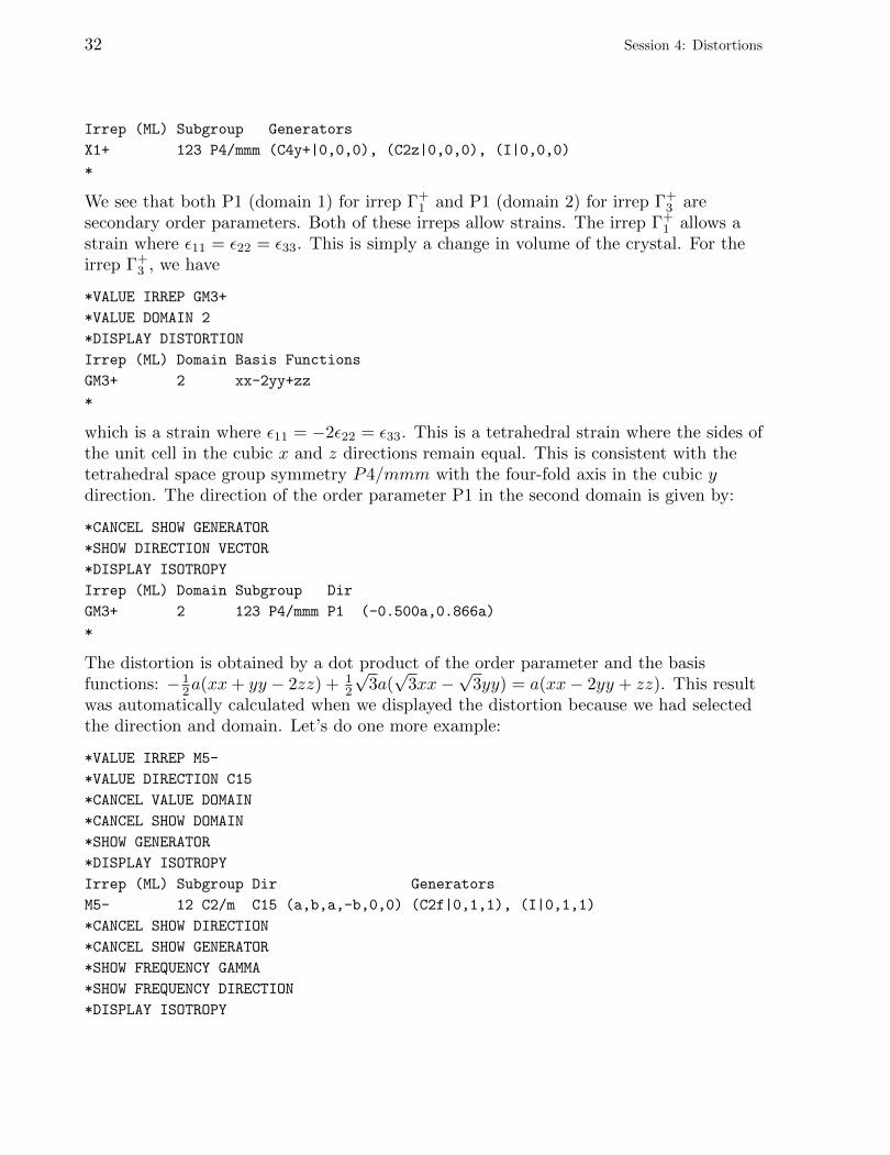
X1+ 123 P4/mmm (C4y+|0,0,0), (C2z|0,0,0), (I|0,0,0)
*
We see that both P1 (domain 1) for irrep Γ+1 and P1 (domain 2) for irrep Γ+
3 aresecondary order parameters. Both of these irreps allow strains. The irrep Γ+
1 allows astrain where ε11 = ε22 = ε33. This is simply a change in volume of the crystal. For theirrep Γ+
3 , we have
*VALUE IRREP GM3+
*VALUE DOMAIN 2
*DISPLAY DISTORTION
Irrep (ML) Domain Basis Functions
GM3+ 2 xx-2yy+zz
*
which is a strain where ε11 = −2ε22 = ε33. This is a tetrahedral strain where the sides ofthe unit cell in the cubic x and z directions remain equal. This is consistent with thetetrahedral space group symmetry P4/mmm with the four-fold axis in the cubic ydirection. The direction of the order parameter P1 in the second domain is given by:
*CANCEL SHOW GENERATOR
*SHOW DIRECTION VECTOR
*DISPLAY ISOTROPY
Irrep (ML) Domain Subgroup Dir
GM3+ 2 123 P4/mmm P1 (-0.500a,0.866a)
*
The distortion is obtained by a dot product of the order parameter and the basisfunctions: − 1
2a(xx+ yy − 2zz) + 12
√3a(√
3xx−√
3yy) = a(xx− 2yy + zz). This resultwas automatically calculated when we displayed the distortion because we had selectedthe direction and domain. Let’s do one more example:
*VALUE IRREP M5-
*VALUE DIRECTION C15
*CANCEL VALUE DOMAIN
*CANCEL SHOW DOMAIN
*SHOW GENERATOR
*DISPLAY ISOTROPY
Irrep (ML) Subgroup Dir Generators
M5- 12 C2/m C15 (a,b,a,-b,0,0) (C2f|0,1,1), (I|0,1,1)
*CANCEL SHOW DIRECTION
*CANCEL SHOW GENERATOR
*SHOW FREQUENCY GAMMA
*SHOW FREQUENCY DIRECTION
*DISPLAY ISOTROPY
Session 4: Distortions 33
Irrep (ML) Subgroup Frequency
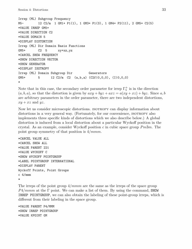
M5- 12 C2/m 1 GM1+ P1(1), 1 GM3+ P1(3), 1 GM4+ P2(11), 2 GM5+ C2(5)
*VALUE IRREP GM5+
*VALUE DIRECTION C2
*VALUE DOMAIN 5
*DISPLAY DISTORTION
Irrep (ML) Dir Domain Basis Functions
GM5+ C2 5 xy+xz,yz
*CANCEL SHOW FREQUENCY
*SHOW DIRECTION VECTOR
*SHOW GENERATOR
*DISPLAY ISOTROPY
Irrep (ML) Domain Subgroup Dir Generators
GM5+ 5 12 C2/m C2 (a,b,a) (C2f|0,0,0), (I|0,0,0)
*
Note that in this case, the secondary order parameter for irrep Γ+5 is in the direction
(a, b, a), so that the distortion is given by axy + byz + axz = a(xy + xz) + byz. Since a, bare arbitrary parameters in the order parameter, there are two independent distortions,xy + xz and yz.
Now let us consider microscopic distortions. isotropy can display information aboutdistortions in a very general way. (Fortunately, for our convenience, isotropy alsoimplements three specific kinds of distortions which we also describe below.) A globaldistortion is induced from a local distortion about a particular Wyckoff position in thecrystal. As an example, consider Wyckoff position c in cubic space group Pm3m. Thepoint group symmetry of that position is 4/mmm.
*CANCEL VALUE ALL
*CANCEL SHOW ALL
*VALUE PARENT 221
*VALUE WYCKOFF C
*SHOW WYCKOFF POINTGROUP
*LABEL POINTGROUP INTERNATIONAL
*DISPLAY PARENT
Wyckoff Points, Point Groups
c 4/mmm
*
The irreps of the point group 4/mmm are the same as the irreps of the space groupP4/mmm at the Γ point. We can make a list of them. By using the command, SHOWIRREP POINTGROUP, we can also obtain the labeling of these point-group irreps, which isdifferent from their labeling in the space group.
*VALUE PARENT P4/MMM
*SHOW IRREP POINTGROUP
*VALUE KPOINT GM
34 Session 4: Distortions
*DISPLAY IRREP
Irrep (ML)
GM1+ A1g
GM2+ B1g
GM3+ A2g
GM4+ B2g
GM5+ Eg
GM1- A1u
GM2- B1u
GM3- A2u
GM4- B2u
GM5- Eu
*
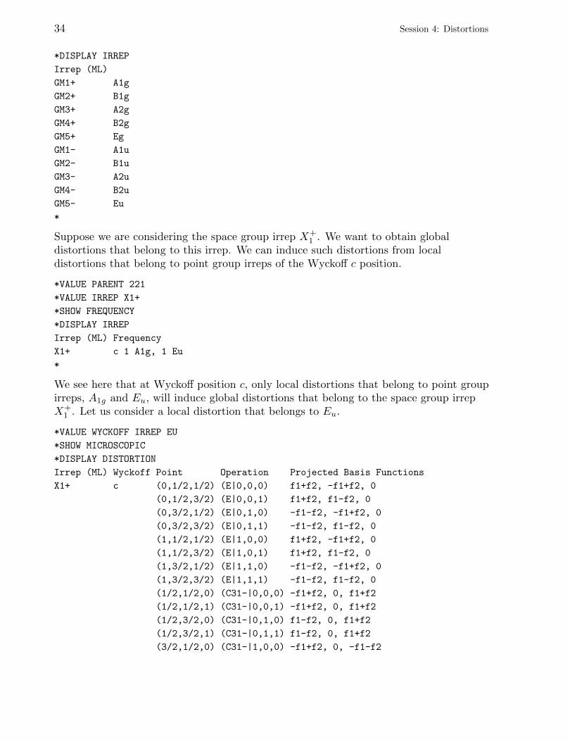
Suppose we are considering the space group irrep X+1 . We want to obtain global
distortions that belong to this irrep. We can induce such distortions from localdistortions that belong to point group irreps of the Wyckoff c position.
*VALUE PARENT 221
*VALUE IRREP X1+
*SHOW FREQUENCY
*DISPLAY IRREP
Irrep (ML) Frequency
X1+ c 1 A1g, 1 Eu
*
We see here that at Wyckoff position c, only local distortions that belong to point groupirreps, A1g and Eu, will induce global distortions that belong to the space group irrepX+
1 . Let us consider a local distortion that belongs to Eu.
*VALUE WYCKOFF IRREP EU
*SHOW MICROSCOPIC
*DISPLAY DISTORTION
Irrep (ML) Wyckoff Point Operation Projected Basis Functions
X1+ c (0,1/2,1/2) (E|0,0,0) f1+f2, -f1+f2, 0
(0,1/2,3/2) (E|0,0,1) f1+f2, f1-f2, 0
(0,3/2,1/2) (E|0,1,0) -f1-f2, -f1+f2, 0
(0,3/2,3/2) (E|0,1,1) -f1-f2, f1-f2, 0
(1,1/2,1/2) (E|1,0,0) f1+f2, -f1+f2, 0
(1,1/2,3/2) (E|1,0,1) f1+f2, f1-f2, 0
(1,3/2,1/2) (E|1,1,0) -f1-f2, -f1+f2, 0
(1,3/2,3/2) (E|1,1,1) -f1-f2, f1-f2, 0
(1/2,1/2,0) (C31-|0,0,0) -f1+f2, 0, f1+f2
(1/2,1/2,1) (C31-|0,0,1) -f1+f2, 0, f1+f2
(1/2,3/2,0) (C31-|0,1,0) f1-f2, 0, f1+f2
(1/2,3/2,1) (C31-|0,1,1) f1-f2, 0, f1+f2
(3/2,1/2,0) (C31-|1,0,0) -f1+f2, 0, -f1-f2
Session 4: Distortions 35
(3/2,1/2,1) (C31-|1,0,1) -f1+f2, 0, -f1-f2
(3/2,3/2,0) (C31-|1,1,0) f1-f2, 0, -f1-f2
(3/2,3/2,1) (C31-|1,1,1) f1-f2, 0, -f1-f2
(1/2,0,1/2) (C31+|0,0,0) 0, f1+f2, -f1+f2
(1/2,0,3/2) (C31+|0,0,1) 0, -f1-f2, -f1+f2
(1/2,1,1/2) (C31+|0,1,0) 0, f1+f2, -f1+f2
(1/2,1,3/2) (C31+|0,1,1) 0, -f1-f2, -f1+f2
(3/2,0,1/2) (C31+|1,0,0) 0, f1+f2, f1-f2
(3/2,0,3/2) (C31+|1,0,1) 0, -f1-f2, f1-f2
(3/2,1,1/2) (C31+|1,1,0) 0, f1+f2, f1-f2
(3/2,1,3/2) (C31+|1,1,1) 0, -f1-f2, f1-f2
*
In the column labeled “Point” are the positions of the atoms inside the unit cell of thekernel of X+
1 . f1 and f2 are local distortions at (0, 12 ,12 ) which transform like the basis
functions of the two-dimensional point group irrep Eu. The projected basis functions arethe global distortions at each point that transform like the basis functions of thethree-dimensional space-group irrep X+
1 . In the column labeled “Operation” are elementsof the space group which take the first point (0, 12 ,
12 ) to the point on the corresponding
row. For example, {C+31|0, 1, 0}(0, 12 ,
12 ) = ( 1
2 , 1,12 ). Each local distortion in the projected
basis functions must be operated on by the point operator in that element. For example,the projected basis functions at ( 1
2 , 1,12 ) are actually 0, C+
31(f1 + f2), C+31(−f1 + f2).
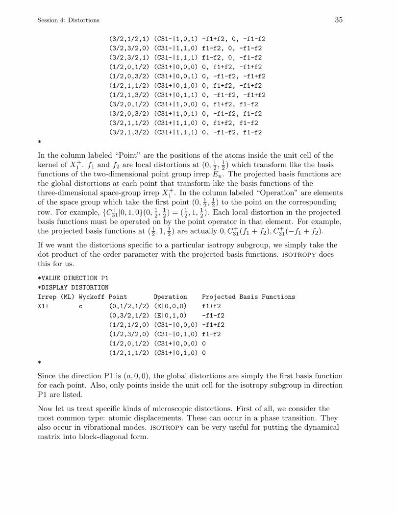
If we want the distortions specific to a particular isotropy subgroup, we simply take thedot product of the order parameter with the projected basis functions. isotropy doesthis for us.
*VALUE DIRECTION P1
*DISPLAY DISTORTION
Irrep (ML) Wyckoff Point Operation Projected Basis Functions
X1+ c (0,1/2,1/2) (E|0,0,0) f1+f2
(0,3/2,1/2) (E|0,1,0) -f1-f2
(1/2,1/2,0) (C31-|0,0,0) -f1+f2
(1/2,3/2,0) (C31-|0,1,0) f1-f2
(1/2,0,1/2) (C31+|0,0,0) 0
(1/2,1,1/2) (C31+|0,1,0) 0
*
Since the direction P1 is (a, 0, 0), the global distortions are simply the first basis functionfor each point. Also, only points inside the unit cell for the isotropy subgroup in directionP1 are listed.
Now let us treat specific kinds of microscopic distortions. First of all, we consider themost common type: atomic displacements. These can occur in a phase transition. Theyalso occur in vibrational modes. isotropy can be very useful for putting the dynamicalmatrix into block-diagonal form.
36 Session 4: Distortions
As an example of atomic displacements, consider a phase transition in a perovskitecrystal. The parent space group is the cubic Pm3m, and the irrep is Γ−4 . The atoms areat Wyckoff positions a, b, c. The direction of the order parameter is P2.
*CANCEL VALUE ALL
*CANCEL SHOW ALL
*VALUE PARENT 221
*VALUE IRREP GM4-
*VALUE DIR P2
*VALUE WYCKOFF A B C
*SHOW DIRECTION VECTOR
*SHOW SUBGROUP
*SHOW BASIS
*DISPLAY ISOTROPY
Subgroup Dir Basis Vectors
38 Amm2 P2 (a,a,0) (0,0,1),(1,-1,0),(1,1,0)
*SHOW WYCKOFF
*SHOW MICROSCOPIC VECTOR
*DISPLAY DISTORTION
Dir Wyckoff Point Projected Vectors
P2 a (0,0,0) (1,1,0)
P2 b (1/2,1/2,1/2) (1,1,0)
P2 c (0,1/2,1/2) (1,0,0)
(1/2,1/2,0) (0,0,0)
(1/2,0,1/2) (0,1,0)
P2 c (0,1/2,1/2) (0,2,0)
(1/2,1/2,0) (2,2,0)
(1/2,0,1/2) (2,0,0)
*
The isotropy subgroup is orthorhombic. Global distortions are induced by a localdistortion at Wyckoff position a and at position b and by two different local distortionsat position c. We do not need to specify the point group irreps. isotropy tries all ofthem and finds the ones that induce global distortions that belong to Γ−4 . We can alsodisplay the atomic positions and displacements in cartesian coordinates:
*VALUE LATTICE PARAMETER 3.88 3.88 3.88 90 90 90
*VALUE WYCKOFF XYZ 0 0 0
*SHOW CARTESIAN
*DISPLAY DISTORTION
Dir Wyckoff Point Projected Vectors
P2 a (0.00000, 0.00000, 0.00000) (3.88000, 3.88000, 0.00000)
P2 b (1.94000, 1.94000, 1.94000) (3.88000, 3.88000, 0.00000)
P2 c (0.00000, 1.94000, 1.94000) (3.88000, 0.00000, 0.00000)
(1.94000, 1.94000, 0.00000) (0.00000, 0.00000, 0.00000)
(1.94000, 0.00000, 1.94000) (0.00000, 3.88000, 0.00000)
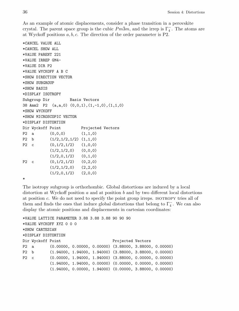
Session 4: Distortions 37
P2 c (0.00000, 1.94000, 1.94000) (0.00000, 7.76000, 0.00000)
(1.94000, 1.94000, 0.00000) (7.76000, 7.76000, 0.00000)
(1.94000, 0.00000, 1.94000) (7.76000, 0.00000, 0.00000)
*
These are atomic displacements due to the primary order parameter. Let us look foratomic displacements due to secondary order parameters.
*CANCEL SHOW CARTESIAN
*CANCEL VALUE WYCKOFF XYZ
*CANCEL SHOW BASIS
*SHOW FREQUENCY DIRECTION
*DISPLAY ISOTROPY
Subgroup Dir Frequency
38 Amm2 P2 (a,a,0) 1 GM1+ P1(1), 1 GM3+ P1(1), 1 GM5+ P1(1), 1 GM4- P2(1), 1
GM5- P2(10)
*VALUE IRREP GM1+
*VALUE DIRECTION P1
*DISPLAY DISTORTION
*VALUE IRREP GM3+
*DISPLAY DISTORTION
*VALUE IRREP GM5+
*DISPLAY DISTORTION
*VALUE IRREP GM5-
*VALUE DIRECTION P2
*VALUE DOMAIN 10
*DISPLAY DISTORTION
Dir Domain Wyckoff Point Projected Vectors
P2 10 c (0,1/2,1/2) (0,-2,0)
(1/2,1/2,0) (2,2,0)
(1/2,0,1/2) (-2,0,0)
*
We first find that secondary order parameters occur for irreps Γ+1 , Γ+
3 , Γ+5 , Γ−5 . We try
them one at a time. If there is no data displayed in response to the DISPLAY DISTORTION
command, then no local atomic displacements can induce a global distortion for thatspace group irrep. We see that the only secondary order parameter that produces atomicdisplacement distortions is P2 (domain 10) for irrep Γ−5 . This global distortion involvesonly displacements of the atoms at Wyckoff position c.
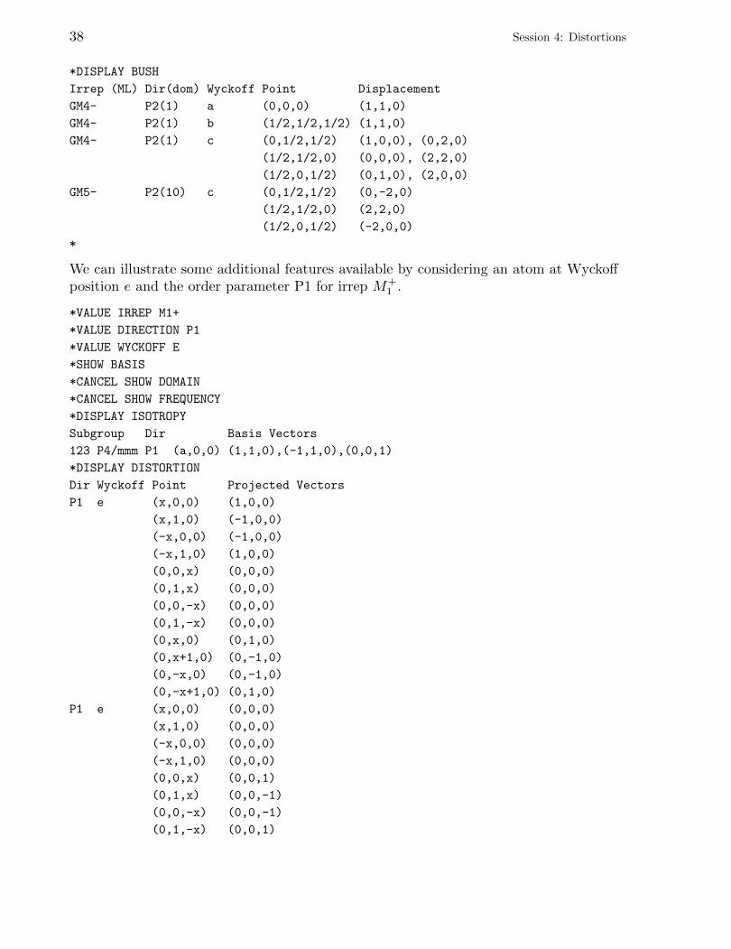
The collection of primary and secondary modes is called a “bush” of modes. We candisplay the entire bush with one command.
*VALUE IRREP GM4-
*VALUE DIRECTION P2
*CANCEL VALUE DOMAIN
*SHOW MODES
38 Session 4: Distortions
*DISPLAY BUSH
Irrep (ML) Dir(dom) Wyckoff Point Displacement
GM4- P2(1) a (0,0,0) (1,1,0)
GM4- P2(1) b (1/2,1/2,1/2) (1,1,0)
GM4- P2(1) c (0,1/2,1/2) (1,0,0), (0,2,0)
(1/2,1/2,0) (0,0,0), (2,2,0)
(1/2,0,1/2) (0,1,0), (2,0,0)
GM5- P2(10) c (0,1/2,1/2) (0,-2,0)
(1/2,1/2,0) (2,2,0)
(1/2,0,1/2) (-2,0,0)
*
We can illustrate some additional features available by considering an atom at Wyckoffposition e and the order parameter P1 for irrep M+
1 .
*VALUE IRREP M1+
*VALUE DIRECTION P1
*VALUE WYCKOFF E
*SHOW BASIS
*CANCEL SHOW DOMAIN
*CANCEL SHOW FREQUENCY
*DISPLAY ISOTROPY
Subgroup Dir Basis Vectors
123 P4/mmm P1 (a,0,0) (1,1,0),(-1,1,0),(0,0,1)
*DISPLAY DISTORTION
Dir Wyckoff Point Projected Vectors
P1 e (x,0,0) (1,0,0)
(x,1,0) (-1,0,0)
(-x,0,0) (-1,0,0)
(-x,1,0) (1,0,0)
(0,0,x) (0,0,0)
(0,1,x) (0,0,0)
(0,0,-x) (0,0,0)
(0,1,-x) (0,0,0)
(0,x,0) (0,1,0)
(0,x+1,0) (0,-1,0)
(0,-x,0) (0,-1,0)
(0,-x+1,0) (0,1,0)
P1 e (x,0,0) (0,0,0)
(x,1,0) (0,0,0)
(-x,0,0) (0,0,0)
(-x,1,0) (0,0,0)
(0,0,x) (0,0,1)
(0,1,x) (0,0,-1)
(0,0,-x) (0,0,-1)
(0,1,-x) (0,0,1)
Session 4: Distortions 39
(0,x,0) (0,0,0)
(0,x+1,0) (0,0,0)
(0,-x,0) (0,0,0)
(0,-x+1,0) (0,0,0)
*
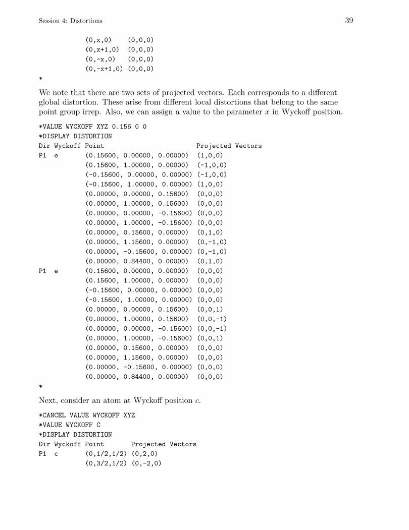
We note that there are two sets of projected vectors. Each corresponds to a differentglobal distortion. These arise from different local distortions that belong to the samepoint group irrep. Also, we can assign a value to the parameter x in Wyckoff position.
*VALUE WYCKOFF XYZ 0.156 0 0
*DISPLAY DISTORTION
Dir Wyckoff Point Projected Vectors
P1 e (0.15600, 0.00000, 0.00000) (1,0,0)
(0.15600, 1.00000, 0.00000) (-1,0,0)
(-0.15600, 0.00000, 0.00000) (-1,0,0)
(-0.15600, 1.00000, 0.00000) (1,0,0)
(0.00000, 0.00000, 0.15600) (0,0,0)
(0.00000, 1.00000, 0.15600) (0,0,0)
(0.00000, 0.00000, -0.15600) (0,0,0)
(0.00000, 1.00000, -0.15600) (0,0,0)
(0.00000, 0.15600, 0.00000) (0,1,0)
(0.00000, 1.15600, 0.00000) (0,-1,0)
(0.00000, -0.15600, 0.00000) (0,-1,0)
(0.00000, 0.84400, 0.00000) (0,1,0)
P1 e (0.15600, 0.00000, 0.00000) (0,0,0)
(0.15600, 1.00000, 0.00000) (0,0,0)
(-0.15600, 0.00000, 0.00000) (0,0,0)
(-0.15600, 1.00000, 0.00000) (0,0,0)
(0.00000, 0.00000, 0.15600) (0,0,1)
(0.00000, 1.00000, 0.15600) (0,0,-1)
(0.00000, 0.00000, -0.15600) (0,0,-1)
(0.00000, 1.00000, -0.15600) (0,0,1)
(0.00000, 0.15600, 0.00000) (0,0,0)
(0.00000, 1.15600, 0.00000) (0,0,0)
(0.00000, -0.15600, 0.00000) (0,0,0)
(0.00000, 0.84400, 0.00000) (0,0,0)
*
Next, consider an atom at Wyckoff position c.
*CANCEL VALUE WYCKOFF XYZ
*VALUE WYCKOFF C
*DISPLAY DISTORTION
Dir Wyckoff Point Projected Vectors
P1 c (0,1/2,1/2) (0,2,0)
(0,3/2,1/2) (0,-2,0)

40 Session 4: Distortions
(1/2,1/2,0) (0,0,0)
(1/2,3/2,0) (0,0,0)
(1/2,0,1/2) (2,0,0)
(1/2,1,1/2) (-2,0,0)
*
We can control which points are displayed. By default, the points inside the unit cell ofthe isotropy subgroup are displayed. All other points can be obtained by translationsusing lattice vectors of the isotropy subgroup. It may sometimes be more convenient,though, to display more points. We can define a cell containing the points to bedisplayed.
*VALUE CELL 2,0,0 0,2,0 0,0,2
*DISPLAY DISTORTION
Dir Wyckoff Point Projected Vectors
P1 c (0,1/2,1/2) (0,2,0)
(0,1/2,3/2) (0,2,0)
(0,3/2,1/2) (0,-2,0)
(0,3/2,3/2) (0,-2,0)
(1,1/2,1/2) (0,-2,0)
(1,1/2,3/2) (0,-2,0)
(1,3/2,1/2) (0,2,0)
(1,3/2,3/2) (0,2,0)
(1/2,1/2,0) (0,0,0)
(1/2,1/2,1) (0,0,0)
(1/2,3/2,0) (0,0,0)
(1/2,3/2,1) (0,0,0)
(3/2,1/2,0) (0,0,0)
(3/2,1/2,1) (0,0,0)
(3/2,3/2,0) (0,0,0)
(3/2,3/2,1) (0,0,0)
(1/2,0,1/2) (2,0,0)
(1/2,0,3/2) (2,0,0)
(1/2,1,1/2) (-2,0,0)
(1/2,1,3/2) (-2,0,0)
(3/2,0,1/2) (-2,0,0)
(3/2,0,3/2) (-2,0,0)
(3/2,1,1/2) (2,0,0)
(3/2,1,3/2) (2,0,0)
*
Now let us consider another kind of microscopic distortion: rotations. These arepseudovectors. Consider the order parameter P1 for irrep R−5 and atoms at Wyckoffpositions a, b, c. The atomic displacements are
*CANCEL VALUE CELL
*VALUE IRREP R5-
Session 4: Distortions 41
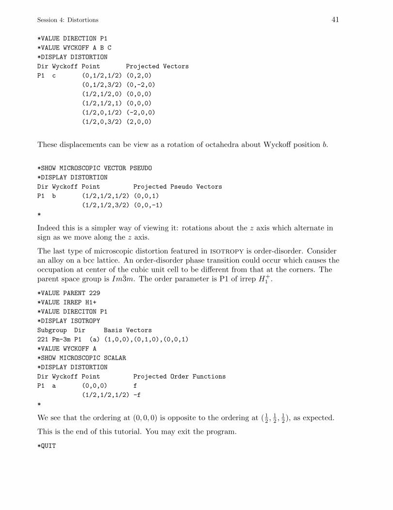
*VALUE DIRECTION P1
*VALUE WYCKOFF A B C
*DISPLAY DISTORTION
Dir Wyckoff Point Projected Vectors
P1 c (0,1/2,1/2) (0,2,0)
(0,1/2,3/2) (0,-2,0)
(1/2,1/2,0) (0,0,0)
(1/2,1/2,1) (0,0,0)
(1/2,0,1/2) (-2,0,0)
(1/2,0,3/2) (2,0,0)
These displacements can be view as a rotation of octahedra about Wyckoff position b.
*SHOW MICROSCOPIC VECTOR PSEUDO
*DISPLAY DISTORTION
Dir Wyckoff Point Projected Pseudo Vectors
P1 b (1/2,1/2,1/2) (0,0,1)
(1/2,1/2,3/2) (0,0,-1)
*
Indeed this is a simpler way of viewing it: rotations about the z axis which alternate insign as we move along the z axis.
The last type of microscopic distortion featured in isotropy is order-disorder. Consideran alloy on a bcc lattice. An order-disorder phase transition could occur which causes theoccupation at center of the cubic unit cell to be different from that at the corners. Theparent space group is Im3m. The order parameter is P1 of irrep H+
1 .
*VALUE PARENT 229
*VALUE IRREP H1+
*VALUE DIRECITON P1
*DISPLAY ISOTROPY
Subgroup Dir Basis Vectors
221 Pm-3m P1 (a) (1,0,0),(0,1,0),(0,0,1)
*VALUE WYCKOFF A
*SHOW MICROSCOPIC SCALAR
*DISPLAY DISTORTION
Dir Wyckoff Point Projected Order Functions
P1 a (0,0,0) f
(1/2,1/2,1/2) -f
*
We see that the ordering at (0, 0, 0) is opposite to the ordering at ( 12 ,
12 ,
12 ), as expected.
This is the end of this tutorial. You may exit the program.
*QUIT

42
Session 5: Invariants
If you have been running isotropy, quit the program and start it again.
In the Landau theory of phase transitions, the free energy of a crystal is expanded interms of components of the order parameter. From symmetry, certain monomials in thisexpansion can be shown to vanish. Similarly, certain monomials can be combined to forminvariant polynomials.
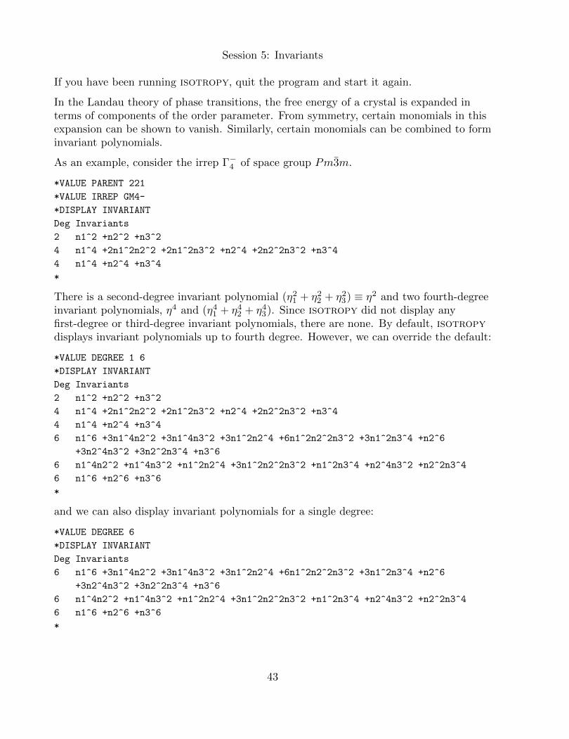
As an example, consider the irrep Γ−4 of space group Pm3m.
*VALUE PARENT 221
*VALUE IRREP GM4-
*DISPLAY INVARIANT
Deg Invariants
2 n1^2 +n2^2 +n3^2
4 n1^4 +2n1^2n2^2 +2n1^2n3^2 +n2^4 +2n2^2n3^2 +n3^4
4 n1^4 +n2^4 +n3^4
*
There is a second-degree invariant polynomial (η21 + η22 + η23) ≡ η2 and two fourth-degreeinvariant polynomials, η4 and (η41 + η42 + η43). Since isotropy did not display anyfirst-degree or third-degree invariant polynomials, there are none. By default, isotropydisplays invariant polynomials up to fourth degree. However, we can override the default:
*VALUE DEGREE 1 6
*DISPLAY INVARIANT
Deg Invariants
2 n1^2 +n2^2 +n3^2
4 n1^4 +2n1^2n2^2 +2n1^2n3^2 +n2^4 +2n2^2n3^2 +n3^4
4 n1^4 +n2^4 +n3^4
6 n1^6 +3n1^4n2^2 +3n1^4n3^2 +3n1^2n2^4 +6n1^2n2^2n3^2 +3n1^2n3^4 +n2^6
+3n2^4n3^2 +3n2^2n3^4 +n3^6
6 n1^4n2^2 +n1^4n3^2 +n1^2n2^4 +3n1^2n2^2n3^2 +n1^2n3^4 +n2^4n3^2 +n2^2n3^4
6 n1^6 +n2^6 +n3^6
*
and we can also display invariant polynomials for a single degree:
*VALUE DEGREE 6
*DISPLAY INVARIANT
Deg Invariants
6 n1^6 +3n1^4n2^2 +3n1^4n3^2 +3n1^2n2^4 +6n1^2n2^2n3^2 +3n1^2n3^4 +n2^6
+3n2^4n3^2 +3n2^2n3^4 +n3^6
6 n1^4n2^2 +n1^4n3^2 +n1^2n2^4 +3n1^2n2^2n3^2 +n1^2n3^4 +n2^4n3^2 +n2^2n3^4
6 n1^6 +n2^6 +n3^6
*
43
44 Session 5: Invariants
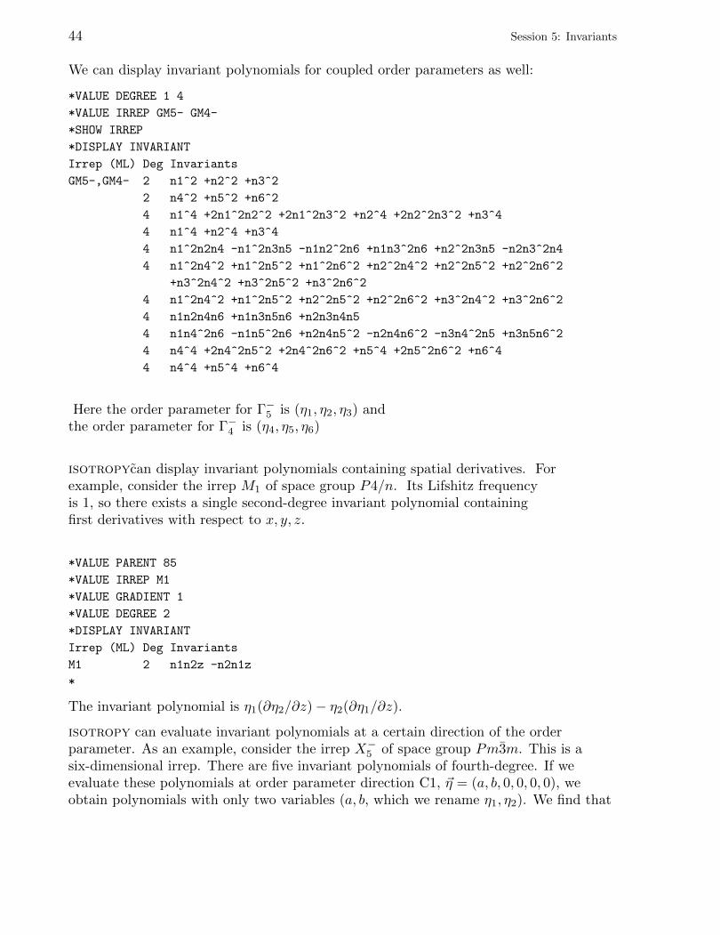
We can display invariant polynomials for coupled order parameters as well:
*VALUE DEGREE 1 4
*VALUE IRREP GM5- GM4-
*SHOW IRREP
*DISPLAY INVARIANT
Irrep (ML) Deg Invariants
GM5-,GM4- 2 n1^2 +n2^2 +n3^2
2 n4^2 +n5^2 +n6^2
4 n1^4 +2n1^2n2^2 +2n1^2n3^2 +n2^4 +2n2^2n3^2 +n3^4
4 n1^4 +n2^4 +n3^4
4 n1^2n2n4 -n1^2n3n5 -n1n2^2n6 +n1n3^2n6 +n2^2n3n5 -n2n3^2n4
4 n1^2n4^2 +n1^2n5^2 +n1^2n6^2 +n2^2n4^2 +n2^2n5^2 +n2^2n6^2
+n3^2n4^2 +n3^2n5^2 +n3^2n6^2
4 n1^2n4^2 +n1^2n5^2 +n2^2n5^2 +n2^2n6^2 +n3^2n4^2 +n3^2n6^2
4 n1n2n4n6 +n1n3n5n6 +n2n3n4n5
4 n1n4^2n6 -n1n5^2n6 +n2n4n5^2 -n2n4n6^2 -n3n4^2n5 +n3n5n6^2
4 n4^4 +2n4^2n5^2 +2n4^2n6^2 +n5^4 +2n5^2n6^2 +n6^4
4 n4^4 +n5^4 +n6^4
Here the order parameter for Γ−5 is (η1, η2, η3) andthe order parameter for Γ−4 is (η4, η5, η6)
isotropycan display invariant polynomials containing spatial derivatives. Forexample, consider the irrep M1 of space group P4/n. Its Lifshitz frequencyis 1, so there exists a single second-degree invariant polynomial containingfirst derivatives with respect to x, y, z.
*VALUE PARENT 85
*VALUE IRREP M1
*VALUE GRADIENT 1
*VALUE DEGREE 2
*DISPLAY INVARIANT
Irrep (ML) Deg Invariants
M1 2 n1n2z -n2n1z
*
The invariant polynomial is η1(∂η2/∂z)− η2(∂η1/∂z).
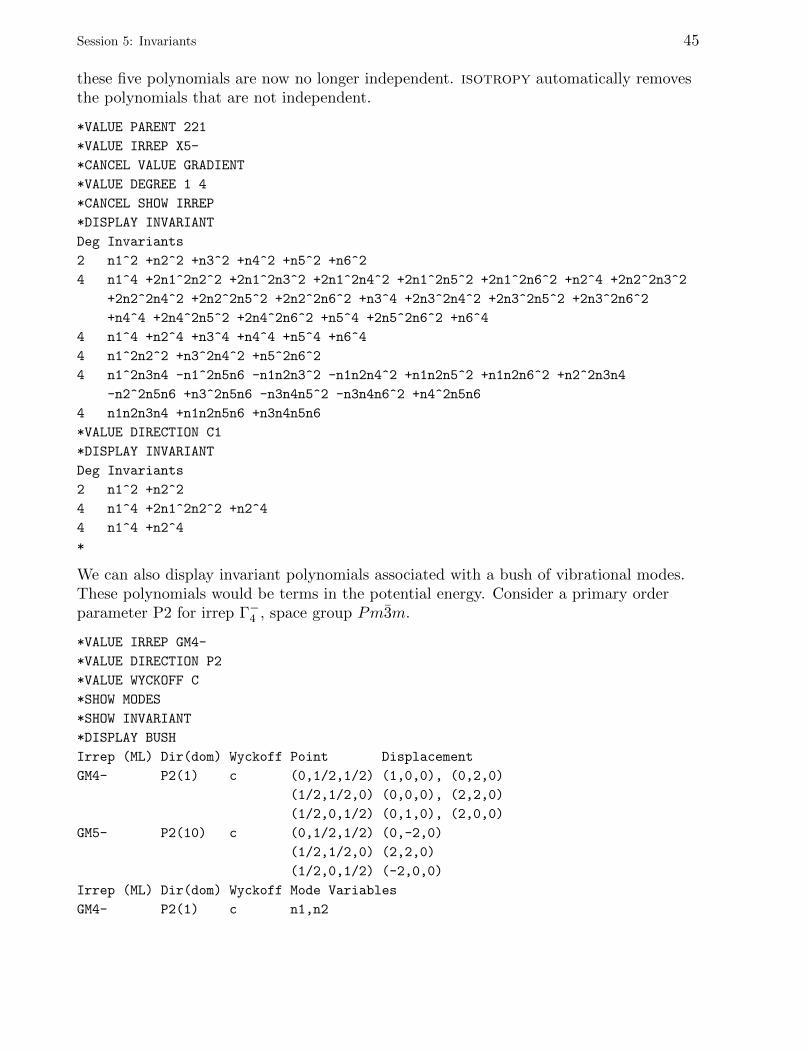
isotropy can evaluate invariant polynomials at a certain direction of the orderparameter. As an example, consider the irrep X−5 of space group Pm3m. This is asix-dimensional irrep. There are five invariant polynomials of fourth-degree. If weevaluate these polynomials at order parameter direction C1, ~η = (a, b, 0, 0, 0, 0), weobtain polynomials with only two variables (a, b, which we rename η1, η2). We find that
Session 5: Invariants 45
these five polynomials are now no longer independent. isotropy automatically removesthe polynomials that are not independent.
*VALUE PARENT 221
*VALUE IRREP X5-
*CANCEL VALUE GRADIENT
*VALUE DEGREE 1 4
*CANCEL SHOW IRREP
*DISPLAY INVARIANT
Deg Invariants
2 n1^2 +n2^2 +n3^2 +n4^2 +n5^2 +n6^2
4 n1^4 +2n1^2n2^2 +2n1^2n3^2 +2n1^2n4^2 +2n1^2n5^2 +2n1^2n6^2 +n2^4 +2n2^2n3^2
+2n2^2n4^2 +2n2^2n5^2 +2n2^2n6^2 +n3^4 +2n3^2n4^2 +2n3^2n5^2 +2n3^2n6^2
+n4^4 +2n4^2n5^2 +2n4^2n6^2 +n5^4 +2n5^2n6^2 +n6^4
4 n1^4 +n2^4 +n3^4 +n4^4 +n5^4 +n6^4
4 n1^2n2^2 +n3^2n4^2 +n5^2n6^2
4 n1^2n3n4 -n1^2n5n6 -n1n2n3^2 -n1n2n4^2 +n1n2n5^2 +n1n2n6^2 +n2^2n3n4
-n2^2n5n6 +n3^2n5n6 -n3n4n5^2 -n3n4n6^2 +n4^2n5n6
4 n1n2n3n4 +n1n2n5n6 +n3n4n5n6
*VALUE DIRECTION C1
*DISPLAY INVARIANT
Deg Invariants
2 n1^2 +n2^2
4 n1^4 +2n1^2n2^2 +n2^4
4 n1^4 +n2^4
*
We can also display invariant polynomials associated with a bush of vibrational modes.These polynomials would be terms in the potential energy. Consider a primary orderparameter P2 for irrep Γ−4 , space group Pm3m.
*VALUE IRREP GM4-
*VALUE DIRECTION P2
*VALUE WYCKOFF C
*SHOW MODES
*SHOW INVARIANT
*DISPLAY BUSH
Irrep (ML) Dir(dom) Wyckoff Point Displacement
GM4- P2(1) c (0,1/2,1/2) (1,0,0), (0,2,0)
(1/2,1/2,0) (0,0,0), (2,2,0)
(1/2,0,1/2) (0,1,0), (2,0,0)
GM5- P2(10) c (0,1/2,1/2) (0,-2,0)
(1/2,1/2,0) (2,2,0)
(1/2,0,1/2) (-2,0,0)
Irrep (ML) Dir(dom) Wyckoff Mode Variables
GM4- P2(1) c n1,n2

46 Session 5: Invariants
GM5- P2(10) c n3
Deg Invariants
2 n1^2
2 n1n2
2 n2^2
2 n3^2
4 n1^4
4 n1^3n2
4 n1^2n2^2
4 n1n2^3
4 n2^4
4 n1^2n3^2
4 n1n2n3^2
4 n2^2n3^2
4 n3^4
4 n1^3n3
4 n1^2n2n3
4 n1n2^2n3
4 n1n3^3
4 n2^3n3
4 n2n3^3
*
There are three modes, two for irrep Γ−4 (primary order parameter or root mode) and onefor Γ−5 (secondary order parameter or secondary mode).
This is the end of this tutorial. You may exit the program.
*QUIT
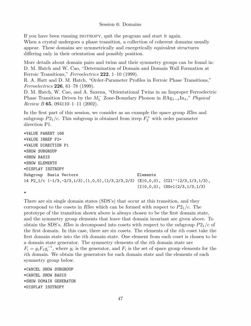
Session 6: Domains
If you have been running isotropy, quit the program and start it again.When a crystal undergoes a phase transition, a collection of coherent domains usuallyappear. These domains are symmetrically and energetically equivalent structuresdiffering only in their orientation and possibly position.
More details about domain pairs and twins and their symmetry groups can be found in:D. M. Hatch and W. Cao, “Determination of Domain and Domain Wall Formation atFerroic Transitions,” Ferroelectrics 222, 1–10 (1999).R. A. Hatt and D. M. Hatch, “Order-Parameter Profiles in Ferroic Phase Transitions,”Ferroelectrics 226, 61–78 (1999).D. M. Hatch, W. Cao, and A. Saxena, “Orientational Twins in an Improper FerroelectricPhase Transition Driven by the M−5 Zone-Boundary Phonon in RAg1−xInx,” PhysicalReview B 65, 094110–1–11 (2002).
In the first part of this session, we consider as an example the space group R3m andsubgroup P21/c. This subgroup is obtained from irrep F+
2 with order parameterdirection P1.
*VALUE PARENT 166
*VALUE IRREP F2+
*VALUE DIRECTION P1
*SHOW SUBGROUP
*SHOW BASIS
*SHOW ELEMENTS
*DISPLAY ISOTROPY
Subgroup Basis Vectors Elements
14 P2_1/c (-1/3,-2/3,1/3),(1,0,0),(1/3,2/3,2/3) (E|0,0,0), (C21’’|2/3,1/3,1/3),
(I|0,0,0), (SGv1|2/3,1/3,1/3)
*
There are six single domain states (SDS’s) that occur at this transition, and theycorrespond to the cosets in R3m which can be formed with respect to P21/c. Theprototype of the transition shown above is always chosen to be the first domain state,and the symmetry group elements that leave that domain invariant are given above. Toobtain the SDS’s, R3m is decomposed into cosets with respect to the subgroup P21/c ofthe first domain. In this case, there are six cosets. The elements of the ith coset take thefirst domain state into the ith domain state. One element from each coset is chosen to bea domain state generator. The symmetry elements of the ith domain state areFi = giF1g
−1i , where gi is the generator, and Fi is the set of space group elements for the
ith domain. We obtain the generators for each domain state and the elements of eachsymmetry group below.
*CANCEL SHOW SUBGROUP
*CANCEL SHOW BASIS
*SHOW DOMAIN GENERATOR
*DISPLAY ISOTROPY
47
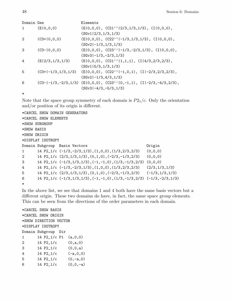
48 Session 6: Domains
Domain Gen Elements
1 (E|0,0,0) (E|0,0,0), (C21’’|2/3,1/3,1/3), (I|0,0,0),
(SGv1|2/3,1/3,1/3)
2 (C3+|0,0,0) (E|0,0,0), (C22’’|-1/3,1/3,1/3), (I|0,0,0),
(SGv2|-1/3,1/3,1/3)
3 (C3-|0,0,0) (E|0,0,0), (C23’’|-1/3,-2/3,1/3), (I|0,0,0),
(SGv3|-1/3,-2/3,1/3)
4 (E|2/3,1/3,1/3) (E|0,0,0), (C21’’|1,1,1), (I|4/3,2/3,2/3),
(SGv1|5/3,1/3,1/3)
5 (C3+|-1/3,1/3,1/3) (E|0,0,0), (C22’’|-1,0,1), (I|-2/3,2/3,2/3),
(SGv2|-1/3,4/3,1/3)
6 (C3-|-1/3,-2/3,1/3) (E|0,0,0), (C23’’|0,-1,1), (I|-2/3,-4/3,2/3),
(SGv3|-4/3,-5/3,1/3)
*
Note that the space group symmetry of each domain is P21/c. Only the orientationand/or position of its origin is different.
*CANCEL SHOW DOMAIN GENERATORS
*CANCEL SHOW ELEMENTS
*SHOW SUBGROUP
*SHOW BASIS
*SHOW ORIGIN
*DISPLAY ISOTROPY
Domain Subgroup Basis Vectors Origin
1 14 P2_1/c (-1/3,-2/3,1/3),(1,0,0),(1/3,2/3,2/3) (0,0,0)
2 14 P2_1/c (2/3,1/3,1/3),(0,1,0),(-2/3,-1/3,2/3) (0,0,0)
3 14 P2_1/c (-1/3,1/3,1/3),(-1,-1,0),(1/3,-1/3,2/3) (0,0,0)
4 14 P2_1/c (-1/3,-2/3,1/3),(1,0,0),(1/3,2/3,2/3) (2/3,1/3,1/3)
5 14 P2_1/c (2/3,1/3,1/3),(0,1,0),(-2/3,-1/3,2/3) (-1/3,1/3,1/3)
6 14 P2_1/c (-1/3,1/3,1/3),(-1,-1,0),(1/3,-1/3,2/3) (-1/3,-2/3,1/3)
*
In the above list, we see that domains 1 and 4 both have the same basis vectors but adifferent origin. These two domains do have, in fact, the same space group elements.This can be seen from the directions of the order parameters in each domain.
*CANCEL SHOW BASIS
*CANCEL SHOW ORIGIN
*SHOW DIRECTION VECTOR
*DISPLAY ISOTROPY
Domain Subgroup Dir
1 14 P2_1/c P1 (a,0,0)
2 14 P2_1/c (0,a,0)
3 14 P2_1/c (0,0,a)
4 14 P2_1/c (-a,0,0)
5 14 P2_1/c (0,-a,0)
6 14 P2_1/c (0,0,-a)
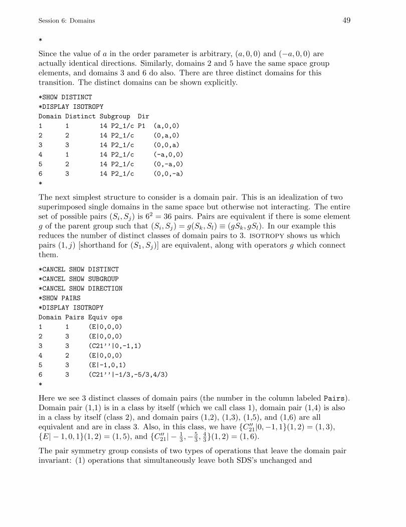
Session 6: Domains 49
*
Since the value of a in the order parameter is arbitrary, (a, 0, 0) and (−a, 0, 0) areactually identical directions. Similarly, domains 2 and 5 have the same space groupelements, and domains 3 and 6 do also. There are three distinct domains for thistransition. The distinct domains can be shown explicitly.
*SHOW DISTINCT
*DISPLAY ISOTROPY
Domain Distinct Subgroup Dir
1 1 14 P2_1/c P1 (a,0,0)
2 2 14 P2_1/c (0,a,0)
3 3 14 P2_1/c (0,0,a)
4 1 14 P2_1/c (-a,0,0)
5 2 14 P2_1/c (0,-a,0)
6 3 14 P2_1/c (0,0,-a)
*
The next simplest structure to consider is a domain pair. This is an idealization of twosuperimposed single domains in the same space but otherwise not interacting. The entireset of possible pairs (Si, Sj) is 62 = 36 pairs. Pairs are equivalent if there is some elementg of the parent group such that (Si, Sj) = g(Sk, Sl) ≡ (gSk, gSl). In our example thisreduces the number of distinct classes of domain pairs to 3. isotropy shows us whichpairs (1, j) [shorthand for (S1, Sj)] are equivalent, along with operators g which connectthem.
*CANCEL SHOW DISTINCT
*CANCEL SHOW SUBGROUP
*CANCEL SHOW DIRECTION
*SHOW PAIRS
*DISPLAY ISOTROPY
Domain Pairs Equiv ops
1 1 (E|0,0,0)
2 3 (E|0,0,0)
3 3 (C21’’|0,-1,1)
4 2 (E|0,0,0)
5 3 (E|-1,0,1)
6 3 (C21’’|-1/3,-5/3,4/3)
*
Here we see 3 distinct classes of domain pairs (the number in the column labeled Pairs).Domain pair (1,1) is in a class by itself (which we call class 1), domain pair (1,4) is alsoin a class by itself (class 2), and domain pairs (1,2), (1,3), (1,5), and (1,6) are allequivalent and are in class 3. Also, in this class, we have {C ′′21|0,−1, 1}(1, 2) = (1, 3),{E| − 1, 0, 1}(1, 2) = (1, 5), and {C ′′21| − 1
3 ,−53 ,
43}(1, 2) = (1, 6).
The pair symmetry group consists of two types of operations that leave the domain pairinvariant: (1) operations that simultaneously leave both SDS’s unchanged and

50 Session 6: Domains
(2) operations, if they exist, that interchange (switch) the two SDS’s. We can write thissymmetry group as
Jij = F(i) ∩ F(j) + j′ijF(i) ∩ F(j),
where F(i) is the space group of the ith domain and j′ij is an element that switches thetwo SDS’s. The first term, F(i) ∩ F(j), is called the pair intersection group. For example,we obtain the pair intersection group for the domain pair (1,2):
*VALUE DOMAIN PAIR 1 2
*SHOW PAIRS INTERSECT
*DISPLAY ISOTROPY
Domain Pairs Pair intersect
(1,2) S1
*
The pair intersection group is always one of the other isotropy subgroups. In this case, itis the isotropy subgroup with the order parameter in the direction S1. We display theelements, basis vectors of the lattice, and origin of this pair intersection group:
*CANCEL SHOW ALL
*VALUE DIRECTION S1
*SHOW SUBGROUP
*SHOW ELEMENTS
*DISPLAY ISOTROPY
Subgroup Elements
2 P-1 (E|0,0,0), (I|0,0,0)
*CANCEL SHOW ELEMENTS
*SHOW BASIS
*SHOW ORIGIN
*DISPLAY ISOTROPY
Subgroup Basis Vectors Origin
2 P-1 (-4/3,-2/3,1/3),(2/3,-2/3,1/3),(2/3,4/3,1/3) (0,0,0)
*
We can also obtain the element j′12 that switches the two SDS’s.
*CANCEL SHOW ALL
*VALUE DIRECTION P1
*VALUE DOMAIN PAIR 1 2
*SHOW PAIRS SWITCH
*DISPLAY ISOTROPY
Domain Pairs Pair switch
(1,2) (C23’’|-1/3,1/3,1/3)
*
Finally, we obtain the pair group:
*CANCEL SHOW PAIRS SWITCH
*SHOW PAIRS GROUP
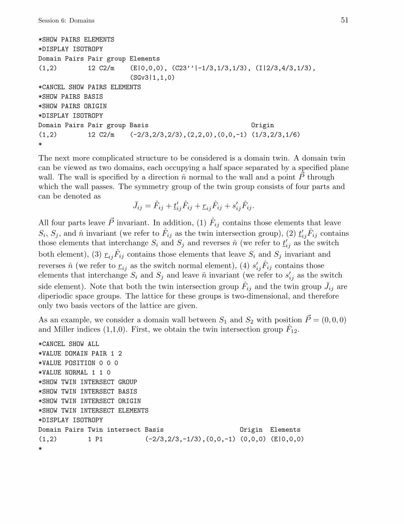
Session 6: Domains 51
*SHOW PAIRS ELEMENTS
*DISPLAY ISOTROPY
Domain Pairs Pair group Elements
(1,2) 12 C2/m (E|0,0,0), (C23’’|-1/3,1/3,1/3), (I|2/3,4/3,1/3),
(SGv3|1,1,0)
*CANCEL SHOW PAIRS ELEMENTS
*SHOW PAIRS BASIS
*SHOW PAIRS ORIGIN
*DISPLAY ISOTROPY
Domain Pairs Pair group Basis Origin
(1,2) 12 C2/m (-2/3,2/3,2/3),(2,2,0),(0,0,-1) (1/3,2/3,1/6)
*
The next more complicated structure to be considered is a domain twin. A domain twincan be viewed as two domains, each occupying a half space separated by a specified planewall. The wall is specified by a direction n normal to the wall and a point ~P throughwhich the wall passes. The symmetry group of the twin group consists of four parts andcan be denoted as
Jij = Fij + t′ijFij + rijFij + s′ijFij .
All four parts leave ~P invariant. In addition, (1) Fij contains those elements that leave
Si, Sj , and n invariant (we refer to Fij as the twin intersection group), (2) t′ijFij containsthose elements that interchange Si and Sj and reverses n (we refer to t′ij as the switch
both element), (3) rijFij contains those elements that leave Si and Sj invariant and
reverses n (we refer to rij as the switch normal element), (4) s′ijFij contains thoseelements that interchange Si and Sj and leave n invariant (we refer to s′ij as the switch
side element). Note that both the twin intersection group Fij and the twin group Jij arediperiodic space groups. The lattice for these groups is two-dimensional, and thereforeonly two basis vectors of the lattice are given.
As an example, we consider a domain wall between S1 and S2 with position ~P = (0, 0, 0)and Miller indices (1,1,0). First, we obtain the twin intersection group F12.
*CANCEL SHOW ALL
*VALUE DOMAIN PAIR 1 2
*VALUE POSITION 0 0 0
*VALUE NORMAL 1 1 0
*SHOW TWIN INTERSECT GROUP
*SHOW TWIN INTERSECT BASIS
*SHOW TWIN INTERSECT ORIGIN
*SHOW TWIN INTERSECT ELEMENTS
*DISPLAY ISOTROPY
Domain Pairs Twin intersect Basis Origin Elements
(1,2) 1 P1 (-2/3,2/3,-1/3),(0,0,-1) (0,0,0) (E|0,0,0)
*

52 Session 6: Domains
We also obtain the switch normal element r12, the switch side element s′12, and theswitch both element t′12.
*CANCEL SHOW TWIN
*SHOW TWIN SWITCH NORMAL
*SHOW TWIN SWITCH SIDE
*SHOW TWIN SWITCH BOTH
*DISPLAY ISOTROPY
Domain Pairs Twin switch normal Twin switch side Twin switch both
(1,2) (I|-2/3,2/3,2/3) (C23’’|-1/3,1/3,1/3) (SGv3|-1/3,1/3,1/3)
*
And finally we obtain the twin symmetry group J12. Notice that it is a diperiodic spacegroup.
*CANCEL SHOW TWIN
*SHOW TWIN GROUP
*SHOW TWIN ELEMENTS
*DISPLAY ISOTROPY
Domain Pairs Twin group Elements
(1,2) 7 P2/b11 (E|0,0,0), (C23’’|-1/3,1/3,-2/3), (I|0,0,0),
(SGv3|-1/3,1/3,-2/3)
*CANCEL SHOW TWIN ELEMENTS
*SHOW TWIN BASIS
*SHOW TWIN ORIGIN
*DISPLAY ISOTROPY
Domain Pairs Twin group Basis Origin
(1,2) 7 P2/b11 (-2/3,2/3,-1/3),(-2/3,2/3,-4/3) (0,0,0)
*
Of course, if the position or orientation of the domain wall is changed, the twin groupwill change. Physical properties of materials such as fatigue, polarization switchingvoltage, etc. depend on domain wall formation, i.e., placement and orientation.
We now consider the average symmetry of a crystal when more than one domain ispresent. We consider as an example a ferroelectric phase transition in a pervoskite crystalfrom the cubic space group Pm3m to the tetragonal subgroup P4mm (order parameterP1, irrep Γ−4 ). There are six domain states associated with this phase transition.
*CANCEL VALUE ALL
*CANCEL SHOW ALL
*VALUE PARENT 221
*VALUE IRREP GM4-
*VALUE DIRECTION P1
*SHOW DOMAINS
*SHOW DIRECTION VECTOR
*DISPLAY ISOTROPY
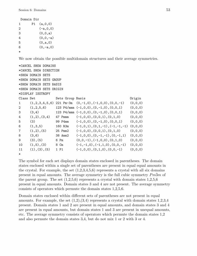
Session 6: Domains 53
Domain Dir
1 P1 (a,0,0)
2 (-a,0,0)
3 (0,0,a)
4 (0,0,-a)
5 (0,a,0)
6 (0,-a,0)
*
We now obtain the possible multidomain structures and their average symmetries.
*CANCEL SHOW DOMAINS
*CANCEL SHOW DIRECTION
*SHOW DOMAIN SETS
*SHOW DOMAIN SETS GROUP
*SHOW DOMAIN SETS BASIS
*SHOW DOMAIN SETS ORIGIN
*DISPLAY ISOTROPY
Class Set Sets Group Basis Origin
1 (1,2,3,4,5,6) 221 Pm-3m (0,-1,0),(-1,0,0),(0,0,-1) (0,0,0)
2 (1,2,5,6) 123 P4/mmm (-1,0,0),(0,-1,0),(0,0,1) (0,0,0)
3 (3,4) 123 P4/mmm (-1,0,0),(0,-1,0),(0,0,1) (0,0,0)
4 (1,2),(3,4) 47 Pmmm (-1,0,0),(0,0,1),(0,1,0) (0,0,0)
5 (3) 99 P4mm (-1,0,0),(0,-1,0),(0,0,1) (0,0,0)
6 (1,3,5) 160 R3m (-1,0,1),(0,1,-1),(-1,-1,-1) (0,0,0)
7 (1,2),(5) 25 Pmm2 (-1,0,0),(0,0,1),(0,1,0) (0,0,0)
8 (3,6) 38 Amm2 (-1,0,0),(0,-1,-1),(0,-1,1) (0,0,0)
9 (3),(5) 6 Pm (0,0,-1),(-1,0,0),(0,1,0) (0,0,0)
10 (1,5),(3) 8 Cm (-1,-1,0),(-1,1,0),(0,0,-1) (0,0,0)
11 (1),(3),(5) 1 P1 (-1,0,0),(0,1,0),(0,0,-1) (0,0,0)
*
The symbol for each set displays domain states enclosed in parentheses. The domainstates enclosed within a single set of parentheses are present in equal equal amounts inthe crystal. For example, the set (1,2,3,4,5,6) represents a crystal with all six domainspresent in equal amounts. The average symmetry is the full cubic symmetry Pm3m ofthe parent group. The set (1,2,5,6) represents a crystal with domain states 1,2,5,6present in equal amounts. Domain states 3 and 4 are not present. The average symmetryconsists of operators which permute the domain states 1,2,5,6.
Domain states enclosed within different sets of parentheses are not present in equalamounts. For example, the set (1,2),(3,4) represents a crystal with domain states 1,2,3,4present. Domain states 1 and 2 are present in equal amounts, and domain states 3 and 4are present in equal amounts, but domain states 1 and 3 are present in unequal amounts,etc. The average symmetry consists of operators which permute the domain states 1,2and also permute the domain states 3,4, but do not mix 1 or 2 with 3 or 4.
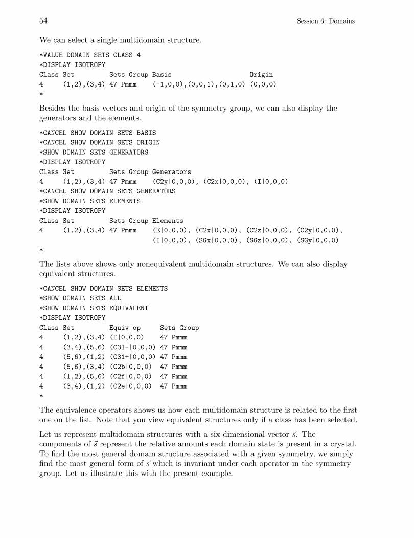
54 Session 6: Domains
We can select a single multidomain structure.
*VALUE DOMAIN SETS CLASS 4
*DISPLAY ISOTROPY
Class Set Sets Group Basis Origin
4 (1,2),(3,4) 47 Pmmm (-1,0,0),(0,0,1),(0,1,0) (0,0,0)
*
Besides the basis vectors and origin of the symmetry group, we can also display thegenerators and the elements.
*CANCEL SHOW DOMAIN SETS BASIS
*CANCEL SHOW DOMAIN SETS ORIGIN
*SHOW DOMAIN SETS GENERATORS
*DISPLAY ISOTROPY
Class Set Sets Group Generators
4 (1,2),(3,4) 47 Pmmm (C2y|0,0,0), (C2x|0,0,0), (I|0,0,0)
*CANCEL SHOW DOMAIN SETS GENERATORS
*SHOW DOMAIN SETS ELEMENTS
*DISPLAY ISOTROPY
Class Set Sets Group Elements
4 (1,2),(3,4) 47 Pmmm (E|0,0,0), (C2x|0,0,0), (C2z|0,0,0), (C2y|0,0,0),
(I|0,0,0), (SGx|0,0,0), (SGz|0,0,0), (SGy|0,0,0)
*
The lists above shows only nonequivalent multidomain structures. We can also displayequivalent structures.
*CANCEL SHOW DOMAIN SETS ELEMENTS
*SHOW DOMAIN SETS ALL
*SHOW DOMAIN SETS EQUIVALENT
*DISPLAY ISOTROPY
Class Set Equiv op Sets Group
4 (1,2),(3,4) (E|0,0,0) 47 Pmmm
4 (3,4),(5,6) (C31-|0,0,0) 47 Pmmm
4 (5,6),(1,2) (C31+|0,0,0) 47 Pmmm
4 (5,6),(3,4) (C2b|0,0,0) 47 Pmmm
4 (1,2),(5,6) (C2f|0,0,0) 47 Pmmm
4 (3,4),(1,2) (C2e|0,0,0) 47 Pmmm
*
The equivalence operators shows us how each multidomain structure is related to the firstone on the list. Note that you view equivalent structures only if a class has been selected.
Let us represent multidomain structures with a six-dimensional vector ~s. Thecomponents of ~s represent the relative amounts each domain state is present in a crystal.To find the most general domain structure associated with a given symmetry, we simplyfind the most general form of ~s which is invariant under each operator in the symmetrygroup. Let us illustrate this with the present example.
Session 6: Domains 55
*SHOW DOMAIN SETS DIRECTION
*DISPLAY ISOTROPY
Dir Domain Sets Dir Sets Group
1 (a,a,a,a,a,a) 221 Pm-3m
2 (a,a,b,b,a,a) 123 P4/mmm
3 (a,a,b,b,c,c) 47 Pmmm
4 (a,a,b,c,a,a) 99 P4mm
5 (a,b,a,b,a,b) 160 R3m
6 (a,a,b,b,c,d) 25 Pmm2
7 (a,a,b,c,c,b) 38 Amm2
8 (a,b,c,c,d,d) 3 P2
9 (a,b,c,c,b,a) 5 C2
10 (a,a,b,c,d,e) 6 Pm
11 (a,b,c,d,a,b) 8 Cm
12 (a,b,c,d,e,f) 1 P1
*
The first entry ~s = (a, a, a, a, a, a) is the structure with all domain states present in equalamounts: (1,2,3,4,5,6). The second entry is a structure with domain states 1,2,5,6 presentin equal amounts and domain states 3,4 present in equal amounts, i.e., (1,2,5,6),(3,4). Itssymmetry is P4/mmm. It turns out that the symmetry of (1,2,5,6) alone (b = 0) is alsoP4/mmm and that of (3,4) alone (a = 0) is P4/mmm. Therefore we list (1,2,5,6) and(3,4) separately as domain structures. For brevity, we do not list (1,2,5,6),(3,4). We listonly the minimal sets of domain states required for each symmetry.
The list above shows only nonequivalent vectors ~s. To see equivalent vectors, we selectone of the directions. Note that SHOW DOMAIN SETS ALL and SHOW DOMAIN SETS
EQUIVALENT are still in effect. Note that VALUE DOMAIN SETS CLASS only has effect whenviewing classes of sets, whereas VALUE DOMAIN SETS DIRECTION only has effect whenviewing directions of ~s.
*VALUE DOMAIN SETS DIRECTION 6
*DISPLAY ISOTROPY
Dir Domain Sets Dir Equiv op Sets Group
6 (a,a,b,b,c,d) (E|0,0,0) 25 Pmm2
6 (a,a,b,c,d,d) (C31-|0,0,0) 25 Pmm2
6 (a,b,c,c,d,d) (C31+|0,0,0) 25 Pmm2
*
This is the end of this tutorial. You may exit the program.
*QUIT

56
Session 7: Incommensurate Structures and Superspace Groups
If you have been running isotropy, quit the program and start it again.
Crystalline structures with a one-dimensional incommensurate distortion have thesymmetry of the (3+1)-dimensional superspace groups. These are described inT. Janssen, A. Janner, A. Looijenga-Vos, and P. M. de Wolff, “Incommensurate andcommensurate modulated structures,” International Tables for Crystallography, Vol. C.
We can display the generators of each superspace group. Let us do this for superspacegroup #68.4 Ccca(10γ)s00:
*VALUE SUPERSPACEGROUP 68.4
*SHOW SUPERSPACEGROUP
*SHOW GENERATORS
*DISPLAY SUPERSPACEGROUP
Superspace Group Generators
68.4 Ccca(10g)s00 (-x1+1/2,x2,x3+1/2,-2x1+x4), (x1+1/2,-x2,x3+1/2,x4),
(x1+1/2,x2,-x3+1/2,2x1-x4+1/2)
*
Note that the default setting is International Tables with x1, x2, x3, x4 coordinates in(3+1)-dimensional space. We can display all of the representative elements of thissuperspace group:
*CANCEL SHOW GENERATORS
*SHOW ELEMENTS
*DISPLAY SUPERSPACEGROUP
Superspace Group Elements
68.4 Ccca(10g)s00 (x1,x2,x3,x4), (x1,-x2,-x3,2x1-x4+1/2), (-x1,x2,-x3,-x4+1/2),
(-x1,-x2,x3,-2x1+x4), (-x1+1/2,-x2,-x3+1/2,-x4+1/2),
(-x1+1/2,x2,x3+1/2,-2x1+x4), (x1+1/2,-x2,x3+1/2,x4),
(x1+1/2,x2,-x3+1/2,2x1-x4+1/2)
*
Elements of superspace groups can also be expressed in terms of components along thex, y, z, t axes:
*LABEL ELEMENT XYZT
*DISPLAY SUPERSPACEGROUP
Superspace Group Elements
68.4 Ccca(10g)s00 (E,1|0,0,0,), (C2x,-1|0,0,0,1/2), (C2y,-1|0,0,0,1/2),
(C2z,1|0,0,0,), (I,-1|1/2,0,1/2,-1/2g),
(SGx,1|1/2,0,1/2,-1/2-1/2g), (SGy,1|1/2,0,1/2,-1/2-1/2g),
(SGz,-1|1/2,0,1/2,-1/2g)
*
In the x, y, z, t coordinate system, the point operators can be displayed using more thanone type of notation. Above, the notation of Bradley and Cracknell was used, the usual
57
58 Session 7: Incommensurate Structures and Superspace Groups
default notation for point operators. Let’s now display the elements in the notation ofInternational Tables.
*LABEL ELEMENT INTERNATIONAL
*DISPLAY SUPERSPACEGROUP
Superspace Group Elements
68.4 Ccca(10g)s00 (x,y,z,t), (x,-y,-z,-t+1/2), (-x,y,-z,-t+1/2), (-x,-y,z,t),
(-x+1/2,-y,-z+1/2,-t-1/2g), (-x+1/2,y,z+1/2,t-1/2-1/2g),
(x+1/2,-y,z+1/2,t-1/2-1/2g), (x+1/2,y,-z+1/2,-t-1/2g)
*
Translations along the t axis represent phase shifts of the incommensurate wave. We seethat for some of the elements, the phase shift depends on γ and is therefore irrational.We also see that the x, y, z coordinates are never mixed with the t coordinate, unlike thecase of the x1, x2, x3, x4 coordinates, where the x1, x2, x3 coordinates are often mixedwith the x4 coordinate. For example, compare −x1 + 1
2 , x2, x3 + 12 ,−2x1 + x4 and
−x+ 12 , y, z + 1
2 , t−12 −
12γ. This mixing is why we cannot express operations on the
x1, x2, x3, x4 coordinates in a Seitz-like notation. We will continue using the notation ofthe International Tables during the rest of this tutorial.
When a three-dimensional space group is extended to (3+1)-dimensional space, theisotropy subgroups are (3+1)-dimensional superspace groups. These are described inH. T. Stokes, B. J. Campbell, and D. M. Hatch, “Order parameters for phase transitionsto structures with one-dimensional incommensurate modulations,” Acta Cryst. A 63, 365(2007). To obtain these isotropy subgroups, the irreps matrices are truncated andtransformed. For example, consider irrep Y1Y2 of space group #106 P42bc.
*VALUE PARENT 106
*VALUE IRREP Y1Y2
*VALUE KVALUE 1,1/10
*SHOW KPOINT
*DISPLAY KPOINT
k vector
DT (a,1/2,0)
*
Note that we enter the k vector parameter as a rational number (α = 110 ) which would be
an approximation to its irrational value if the distortion were truly incommensurate.Therefore, k ≈ ( 1
10 ,12 , 0). Consider a displacement along the x axis. First, the full irrep:
*CANCEL SHOW KPOINT
*SHOW PARENT
*SHOW MATRIX
*VALUE ELEMENT X+1 Y Z
*DISPLAY IRREP
Session 7: Incommensurate Structures and Superspace Groups 59
106 P4_2bc (x+1,y,z) 0.809 0.000 0.000 0.000 0.588 0.000 0.000 0.000
0.000 0.809 0.000 0.000 0.000 -0.588 0.000 0.000
0.000 0.000 -1.000 0.000 0.000 0.000 0.000 0.000
0.000 0.000 0.000 -1.000 0.000 0.000 0.000 0.000
-0.588 0.000 0.000 0.000 0.809 0.000 0.000 0.000
0.000 0.588 0.000 0.000 0.000 0.809 0.000 0.000
0.000 0.000 0.000 0.000 0.000 0.000 -1.000 0.000
0.000 0.000 0.000 0.000 0.000 0.000 0.000 -1.000
*
Now the truncated irrep:
*VALUE SUBGROUP SUPERSPACEGROUP
*VALUE ELEMENT X+1 Y Z T
*DISPLAY IRREP
Parent Element Matrix
106 P4_2bc x+1,y,z,t 0.809 0.000 0.588 0.000
0.000 0.809 0.000 -0.588
-0.588 0.000 0.809 0.000
0.000 0.588 0.000 0.809
*
We can cancel the effect of the translation by introducing a phase shift:
*VALUE ELEMENT X+1 Y Z T-1/10
*DISPLAY IRREP
Parent Element Matrix
106 P4_2bc x+1,y,z,t-1/10 1 0 0 0
0 1 0 0
0 0 1 0
0 0 0 1
*
Of course, this is a simple translation along x1:
*LABEL ELEMENT X1X2X3X4
*VALUE ELEMENT X1+1 X2 X3 X4
*DISPLAY IRREP
Parent Element Matrix
106 P4_2bc x1+1,x2,x3,x4 1 0 0 0
0 1 0 0
0 0 1 0
0 0 0 1
*
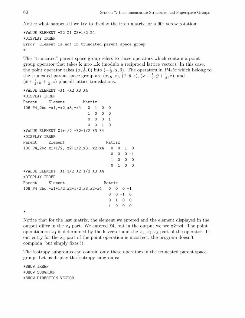
60 Session 7: Incommensurate Structures and Superspace Groups
Notice what happens if we try to display the irrep matrix for a 90◦ screw rotation:
*VALUE ELEMENT -X2 X1 X3+1/2 X4
*DISPLAY IRREP
Error: Element is not in truncated parent space group
*
The “truncated” parent space group refers to those operators which contain a pointgroup operator that takes k into ±k (modulo a reciprocal lattice vector). In this case,the point operator takes (α, 12 , 0) into (− 1
2 , α, 0). The operators in P42bc which belong tothe truncated parent space group are (x, y, z), (x, y, z), (x+ 1
2 , y + 12 , z), and
(x+ 12 , y + 1
2 , z) plus all lattice translations.
*VALUE ELEMENT -X1 -X2 X3 X4
*DISPLAY IRREP
Parent Element Matrix
106 P4_2bc -x1,-x2,x3,-x4 0 1 0 0
1 0 0 0
0 0 0 1
0 0 1 0
*VALUE ELEMENT X1+1/2 -X2+1/2 X3 X4
*DISPLAY IRREP
Parent Element Matrix
106 P4_2bc x1+1/2,-x2+1/2,x3,-x2+x4 0 0 -1 0
0 0 0 -1
1 0 0 0
0 1 0 0
*VALUE ELEMENT -X1+1/2 X2+1/2 X3 X4
*DISPLAY IRREP
Parent Element Matrix
106 P4_2bc -x1+1/2,x2+1/2,x3,x2-x4 0 0 0 -1
0 0 -1 0
0 1 0 0
1 0 0 0
*
Notice that for the last matrix, the element we entered and the element displayed in theoutput differ in the x4 part. We entered X4, but in the output we see x2-x4. The pointoperation on x4 is determined by the k vector and the x1, x2, x3 part of the operator. Ifour entry for the x4 part of the point operation is incorrect, the program doesn’tcomplain, but simply fixes it.
The isotropy subgroups can contain only these operators in the truncated parent spacegroup. Let us display the isotropy subgroups:
*SHOW IRREP
*SHOW SUBGROUP
*SHOW DIRECTION VECTOR

Session 7: Incommensurate Structures and Superspace Groups 61
*CANCEL SHOW ELEMENTS
*DISPLAY ISOTROPY
Parent Irrep (ML) Subgroup Dir
106 P4_2bc Y1Y2 7.2 Pb(ab1/2) P1P1 (a,0,b,0)
106 P4_2bc Y1Y2 3.1 P2(ab0) P3P3 (a,a,b,b)
106 P4_2bc Y1Y2 1.1 P1(abg) C1C1 (a,b,c,d)
*
Let us display the basis vectors and origin:
*CANCEL SHOW PARENT
*CANCEL SHOW IRREP
*CANCEL SHOW DIRECTION VECTOR
*SHOW BASIS
*SHOW ORIGIN
*DISPLAY ISOTROPY
Subgroup Dir Basis Vectors Origin
7.2 Pb(ab1/2) P1P1 (1,0,-1,0),(-1,0,0,0),(0,1,0,0),(0,0,0,1) (0,1/4,0,0)
3.1 P2(ab0) P3P3 (1,0,0,0),(0,1,0,0),(0,0,1,0),(0,0,0,1) (0,0,0,0)
1.1 P1(abg) C1C1 (1,0,0,0),(0,1,0,0),(0,0,1,0),(0,0,0,1) (0,0,0,0)
*
We can also display the generators of the subgroup:
*CANCEL SHOW BASIS
*CANCEL SHOW ORIGIN
*SHOW GENERATORS
*DISPLAY ISOTROPY
Subgroup Dir Generators
7.2 Pb(ab1/2) P1P1 (x1-1/2,-x2+1/2,x3,-x2+x4+1/4)
3.1 P2(ab0) P3P3 (-x1,-x2,x3,-x4)
1.1 P1(abg) C1C1 (x1,x2,x3,x4)
*
as well as all of the elements of the subgroup:
*CANCEL SHOW GENERATORS
*SHOW ELEMENTS
*DISPLAY ISOTROPY
Subgroup Dir Elements
7.2 Pb(ab1/2) P1P1 (x1,x2,x3,x4), (x1-1/2,-x2+1/2,x3,-x2+x4+1/4)
3.1 P2(ab0) P3P3 (x1,x2,x3,x4), (-x1,-x2,x3,-x4)
1.1 P1(abg) C1C1 (x1,x2,x3,x4)
*
Next, let us display the distortions which accompany the superspace-group symmetry. Tokeep things simple, we will consider space group 221 Pm3m, atoms at Wyckoff position(a) 0, 0, 0, and irrep ∆1, where k = (0, 1
12 , 0).
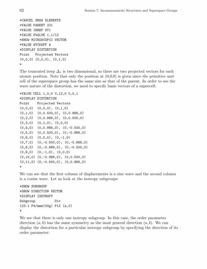
62 Session 7: Incommensurate Structures and Superspace Groups
*CANCEL SHOW ELEMENTS
*VALUE PARENT 221
*VALUE IRREP DT1
*VALUE KVALUE 1,1/12
*SHOW MICROSCOPIC VECTOR
*VALUE WYCKOFF A
*DISPLAY DISTORTION
Point Projected Vectors
(0,0,0) (0,0,0), (0,1,0)
*
The truncated irrep ∆1 is two dimensional, so there are two projected vectors for eachatomic position. Note that only the position at (0,0,0) is given since the primitive unitcell of the superspace group has the same size as that of the parent. In order to see thewave nature of the distortion, we need to specify basis vectors of a supercell:
*VALUE CELL 1,0,0 0,12,0 0,0,1
*DISPLAY DISTORTION
Point Projected Vectors
(0,0,0) (0,0,0), (0,1,0)
(0,1,0) (0,0.500,0), (0,0.866,0)
(0,2,0) (0,0.866,0), (0,0.500,0)
(0,3,0) (0,1,0), (0,0,0)
(0,4,0) (0,0.866,0), (0,-0.500,0)
(0,5,0) (0,0.500,0), (0,-0.866,0)
(0,6,0) (0,0,0), (0,-1,0)
(0,7,0) (0,-0.500,0), (0,-0.866,0)
(0,8,0) (0,-0.866,0), (0,-0.500,0)
(0,9,0) (0,-1,0), (0,0,0)
(0,10,0) (0,-0.866,0), (0,0.500,0)
(0,11,0) (0,-0.500,0), (0,0.866,0)
*
We can see that the first column of displacements is a sine wave and the second columnis a cosine wave. Let us look at the isotropy subgroups:
*SHOW SUBGROUP
*SHOW DIRECTION VECTOR
*DISPLAY ISOTROPY
Subgroup Dir
123.1 P4/mmm(00g) P1Z (a,0)
*
We see that there is only one isotropy subgroup. In this case, the order parameterdirection (a, 0) has the same symmetry as the most general direction (a, b). We candisplay the distortion for a particular isotropy subgroup by specifying the direction of itsorder parameter:

Session 7: Incommensurate Structures and Superspace Groups 63
*VALUE DIRECTION P1Z
*DISPLAY DISTORTION
Dir Point Projected Vectors
P1Z (0,0,0) (0,0,0)
(0,1,0) (0,0.500,0)
(0,2,0) (0,0.866,0)
(0,3,0) (0,1,0)
(0,4,0) (0,0.866,0)
(0,5,0) (0,0.500,0)
(0,6,0) (0,0,0)
(0,7,0) (0,-0.500,0)
(0,8,0) (0,-0.866,0)
(0,9,0) (0,-1,0)
(0,10,0) (0,-0.866,0)
(0,11,0) (0,-0.500,0)
*
This is the end of this tutorial. You may exit the program:
*QUIT

64 Session 7: Incommensurate Structures and Superspace Groups
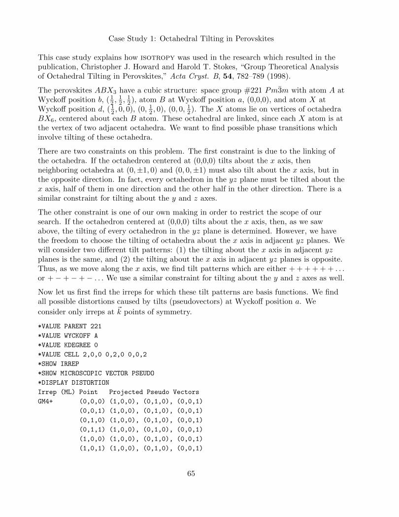
Case Study 1: Octahedral Tilting in Perovskites
This case study explains how isotropy was used in the research which resulted in thepublication, Christopher J. Howard and Harold T. Stokes, “Group Theoretical Analysisof Octahedral Tilting in Perovskites,” Acta Cryst. B, 54, 782–789 (1998).
The perovskites ABX3 have a cubic structure: space group #221 Pm3m with atom A atWyckoff position b, ( 1
2 ,12 ,
12 ), atom B at Wyckoff position a, (0,0,0), and atom X at
Wyckoff position d, ( 12 , 0, 0), (0, 12 , 0), (0, 0, 12 ). The X atoms lie on vertices of octahedra
BX6, centered about each B atom. These octahedral are linked, since each X atom is atthe vertex of two adjacent octahedra. We want to find possible phase transitions whichinvolve tilting of these octahedra.
There are two constraints on this problem. The first constraint is due to the linking ofthe octahedra. If the octahedron centered at (0,0,0) tilts about the x axis, thenneighboring octahedra at (0,±1, 0) and (0, 0,±1) must also tilt about the x axis, but inthe opposite direction. In fact, every octahedron in the yz plane must be tilted about thex axis, half of them in one direction and the other half in the other direction. There is asimilar constraint for tilting about the y and z axes.
The other constraint is one of our own making in order to restrict the scope of oursearch. If the octahedron centered at (0,0,0) tilts about the x axis, then, as we sawabove, the tilting of every octahedron in the yz plane is determined. However, we havethe freedom to choose the tilting of octahedra about the x axis in adjacent yz planes. Wewill consider two different tilt patterns: (1) the tilting about the x axis in adjacent yzplanes is the same, and (2) the tilting about the x axis in adjacent yz planes is opposite.Thus, as we move along the x axis, we find tilt patterns which are either + + + + + + . . .or +−+−+− . . . We use a similar constraint for tilting about the y and z axes as well.
Now let us first find the irreps for which these tilt patterns are basis functions. We findall possible distortions caused by tilts (pseudovectors) at Wyckoff position a. We
consider only irreps at ~k points of symmetry.
*VALUE PARENT 221
*VALUE WYCKOFF A
*VALUE KDEGREE 0
*VALUE CELL 2,0,0 0,2,0 0,0,2
*SHOW IRREP
*SHOW MICROSCOPIC VECTOR PSEUDO
*DISPLAY DISTORTION
Irrep (ML) Point Projected Pseudo Vectors
GM4+ (0,0,0) (1,0,0), (0,1,0), (0,0,1)
(0,0,1) (1,0,0), (0,1,0), (0,0,1)
(0,1,0) (1,0,0), (0,1,0), (0,0,1)
(0,1,1) (1,0,0), (0,1,0), (0,0,1)
(1,0,0) (1,0,0), (0,1,0), (0,0,1)
(1,0,1) (1,0,0), (0,1,0), (0,0,1)
65
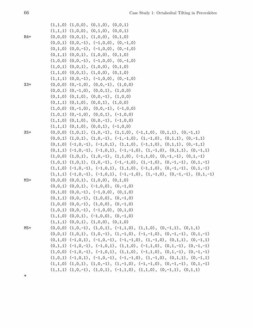
66 Case Study 1: Octahedral Tilting in Perovskites
(1,1,0) (1,0,0), (0,1,0), (0,0,1)
(1,1,1) (1,0,0), (0,1,0), (0,0,1)
R4+ (0,0,0) (0,0,1), (1,0,0), (0,1,0)
(0,0,1) (0,0,-1), (-1,0,0), (0,-1,0)
(0,1,0) (0,0,-1), (-1,0,0), (0,-1,0)
(0,1,1) (0,0,1), (1,0,0), (0,1,0)
(1,0,0) (0,0,-1), (-1,0,0), (0,-1,0)
(1,0,1) (0,0,1), (1,0,0), (0,1,0)
(1,1,0) (0,0,1), (1,0,0), (0,1,0)
(1,1,1) (0,0,-1), (-1,0,0), (0,-1,0)
X3+ (0,0,0) (0,-1,0), (0,0,-1), (1,0,0)
(0,0,1) (0,-1,0), (0,0,1), (1,0,0)
(0,1,0) (0,1,0), (0,0,-1), (1,0,0)
(0,1,1) (0,1,0), (0,0,1), (1,0,0)
(1,0,0) (0,-1,0), (0,0,-1), (-1,0,0)
(1,0,1) (0,-1,0), (0,0,1), (-1,0,0)
(1,1,0) (0,1,0), (0,0,-1), (-1,0,0)
(1,1,1) (0,1,0), (0,0,1), (-1,0,0)
X5+ (0,0,0) (1,0,1), (1,0,-1), (1,1,0), (-1,1,0), (0,1,1), (0,-1,1)
(0,0,1) (1,0,1), (1,0,-1), (-1,-1,0), (1,-1,0), (0,1,1), (0,-1,1)
(0,1,0) (-1,0,-1), (-1,0,1), (1,1,0), (-1,1,0), (0,1,1), (0,-1,1)
(0,1,1) (-1,0,-1), (-1,0,1), (-1,-1,0), (1,-1,0), (0,1,1), (0,-1,1)
(1,0,0) (1,0,1), (1,0,-1), (1,1,0), (-1,1,0), (0,-1,-1), (0,1,-1)
(1,0,1) (1,0,1), (1,0,-1), (-1,-1,0), (1,-1,0), (0,-1,-1), (0,1,-1)
(1,1,0) (-1,0,-1), (-1,0,1), (1,1,0), (-1,1,0), (0,-1,-1), (0,1,-1)
(1,1,1) (-1,0,-1), (-1,0,1), (-1,-1,0), (1,-1,0), (0,-1,-1), (0,1,-1)
M3+ (0,0,0) (0,0,1), (1,0,0), (0,1,0)
(0,0,1) (0,0,1), (-1,0,0), (0,-1,0)
(0,1,0) (0,0,-1), (-1,0,0), (0,1,0)
(0,1,1) (0,0,-1), (1,0,0), (0,-1,0)
(1,0,0) (0,0,-1), (1,0,0), (0,-1,0)
(1,0,1) (0,0,-1), (-1,0,0), (0,1,0)
(1,1,0) (0,0,1), (-1,0,0), (0,-1,0)
(1,1,1) (0,0,1), (1,0,0), (0,1,0)
M5+ (0,0,0) (1,0,-1), (1,0,1), (-1,1,0), (1,1,0), (0,-1,1), (0,1,1)
(0,0,1) (1,0,1), (1,0,-1), (1,-1,0), (-1,-1,0), (0,-1,-1), (0,1,-1)
(0,1,0) (-1,0,1), (-1,0,-1), (-1,-1,0), (1,-1,0), (0,1,1), (0,-1,1)
(0,1,1) (-1,0,-1), (-1,0,1), (1,1,0), (-1,1,0), (0,1,-1), (0,-1,-1)
(1,0,0) (-1,0,-1), (-1,0,1), (1,1,0), (-1,1,0), (0,1,-1), (0,-1,-1)
(1,0,1) (-1,0,1), (-1,0,-1), (-1,-1,0), (1,-1,0), (0,1,1), (0,-1,1)
(1,1,0) (1,0,1), (1,0,-1), (1,-1,0), (-1,-1,0), (0,-1,-1), (0,1,-1)
(1,1,1) (1,0,-1), (1,0,1), (-1,1,0), (1,1,0), (0,-1,1), (0,1,1)
*
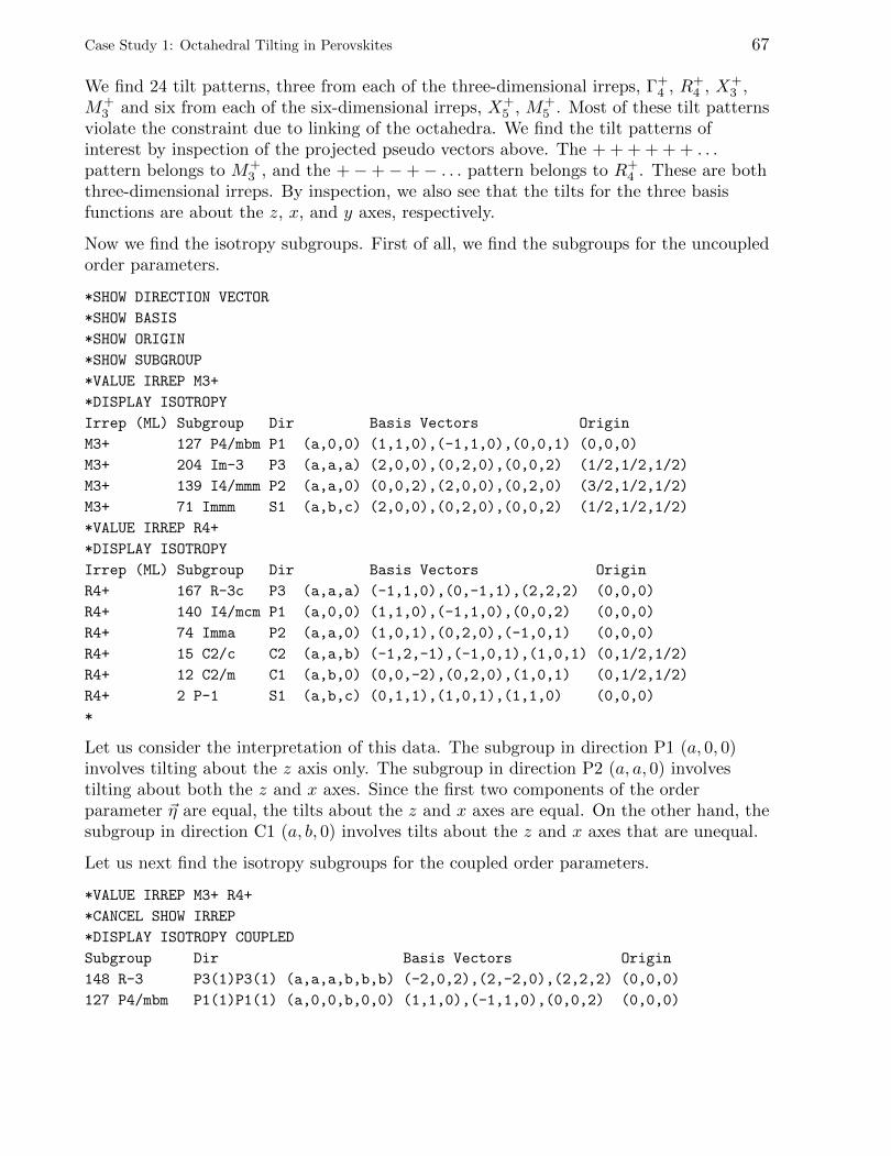
Case Study 1: Octahedral Tilting in Perovskites 67
We find 24 tilt patterns, three from each of the three-dimensional irreps, Γ+4 , R+
4 , X+3 ,
M+3 and six from each of the six-dimensional irreps, X+
5 , M+5 . Most of these tilt patterns
violate the constraint due to linking of the octahedra. We find the tilt patterns ofinterest by inspection of the projected pseudo vectors above. The + + + + + + . . .pattern belongs to M+
3 , and the +−+−+− . . . pattern belongs to R+4 . These are both
three-dimensional irreps. By inspection, we also see that the tilts for the three basisfunctions are about the z, x, and y axes, respectively.
Now we find the isotropy subgroups. First of all, we find the subgroups for the uncoupledorder parameters.
*SHOW DIRECTION VECTOR
*SHOW BASIS
*SHOW ORIGIN
*SHOW SUBGROUP
*VALUE IRREP M3+
*DISPLAY ISOTROPY
Irrep (ML) Subgroup Dir Basis Vectors Origin
M3+ 127 P4/mbm P1 (a,0,0) (1,1,0),(-1,1,0),(0,0,1) (0,0,0)
M3+ 204 Im-3 P3 (a,a,a) (2,0,0),(0,2,0),(0,0,2) (1/2,1/2,1/2)
M3+ 139 I4/mmm P2 (a,a,0) (0,0,2),(2,0,0),(0,2,0) (3/2,1/2,1/2)
M3+ 71 Immm S1 (a,b,c) (2,0,0),(0,2,0),(0,0,2) (1/2,1/2,1/2)
*VALUE IRREP R4+
*DISPLAY ISOTROPY
Irrep (ML) Subgroup Dir Basis Vectors Origin
R4+ 167 R-3c P3 (a,a,a) (-1,1,0),(0,-1,1),(2,2,2) (0,0,0)
R4+ 140 I4/mcm P1 (a,0,0) (1,1,0),(-1,1,0),(0,0,2) (0,0,0)
R4+ 74 Imma P2 (a,a,0) (1,0,1),(0,2,0),(-1,0,1) (0,0,0)
R4+ 15 C2/c C2 (a,a,b) (-1,2,-1),(-1,0,1),(1,0,1) (0,1/2,1/2)
R4+ 12 C2/m C1 (a,b,0) (0,0,-2),(0,2,0),(1,0,1) (0,1/2,1/2)
R4+ 2 P-1 S1 (a,b,c) (0,1,1),(1,0,1),(1,1,0) (0,0,0)
*
Let us consider the interpretation of this data. The subgroup in direction P1 (a, 0, 0)involves tilting about the z axis only. The subgroup in direction P2 (a, a, 0) involvestilting about both the z and x axes. Since the first two components of the orderparameter ~η are equal, the tilts about the z and x axes are equal. On the other hand, thesubgroup in direction C1 (a, b, 0) involves tilts about the z and x axes that are unequal.
Let us next find the isotropy subgroups for the coupled order parameters.
*VALUE IRREP M3+ R4+
*CANCEL SHOW IRREP
*DISPLAY ISOTROPY COUPLED
Subgroup Dir Basis Vectors Origin
148 R-3 P3(1)P3(1) (a,a,a,b,b,b) (-2,0,2),(2,-2,0),(2,2,2) (0,0,0)
127 P4/mbm P1(1)P1(1) (a,0,0,b,0,0) (1,1,0),(-1,1,0),(0,0,2) (0,0,0)
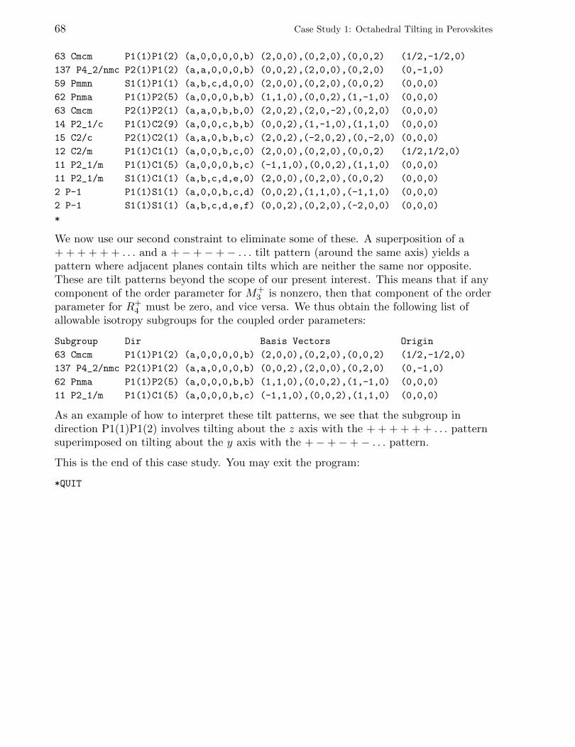
68 Case Study 1: Octahedral Tilting in Perovskites
63 Cmcm P1(1)P1(2) (a,0,0,0,0,b) (2,0,0),(0,2,0),(0,0,2) (1/2,-1/2,0)
137 P4_2/nmc P2(1)P1(2) (a,a,0,0,0,b) (0,0,2),(2,0,0),(0,2,0) (0,-1,0)
59 Pmmn S1(1)P1(1) (a,b,c,d,0,0) (2,0,0),(0,2,0),(0,0,2) (0,0,0)
62 Pnma P1(1)P2(5) (a,0,0,0,b,b) (1,1,0),(0,0,2),(1,-1,0) (0,0,0)
63 Cmcm P2(1)P2(1) (a,a,0,b,b,0) (2,0,2),(2,0,-2),(0,2,0) (0,0,0)
14 P2_1/c P1(1)C2(9) (a,0,0,c,b,b) (0,0,2),(1,-1,0),(1,1,0) (0,0,0)
15 C2/c P2(1)C2(1) (a,a,0,b,b,c) (2,0,2),(-2,0,2),(0,-2,0) (0,0,0)
12 C2/m P1(1)C1(1) (a,0,0,b,c,0) (2,0,0),(0,2,0),(0,0,2) (1/2,1/2,0)
11 P2_1/m P1(1)C1(5) (a,0,0,0,b,c) (-1,1,0),(0,0,2),(1,1,0) (0,0,0)
11 P2_1/m S1(1)C1(1) (a,b,c,d,e,0) (2,0,0),(0,2,0),(0,0,2) (0,0,0)
2 P-1 P1(1)S1(1) (a,0,0,b,c,d) (0,0,2),(1,1,0),(-1,1,0) (0,0,0)
2 P-1 S1(1)S1(1) (a,b,c,d,e,f) (0,0,2),(0,2,0),(-2,0,0) (0,0,0)
*
We now use our second constraint to eliminate some of these. A superposition of a+ + + + + + . . . and a +−+−+− . . . tilt pattern (around the same axis) yields apattern where adjacent planes contain tilts which are neither the same nor opposite.These are tilt patterns beyond the scope of our present interest. This means that if anycomponent of the order parameter for M+
3 is nonzero, then that component of the orderparameter for R+
4 must be zero, and vice versa. We thus obtain the following list ofallowable isotropy subgroups for the coupled order parameters:
Subgroup Dir Basis Vectors Origin
63 Cmcm P1(1)P1(2) (a,0,0,0,0,b) (2,0,0),(0,2,0),(0,0,2) (1/2,-1/2,0)
137 P4_2/nmc P2(1)P1(2) (a,a,0,0,0,b) (0,0,2),(2,0,0),(0,2,0) (0,-1,0)
62 Pnma P1(1)P2(5) (a,0,0,0,b,b) (1,1,0),(0,0,2),(1,-1,0) (0,0,0)
11 P2_1/m P1(1)C1(5) (a,0,0,0,b,c) (-1,1,0),(0,0,2),(1,1,0) (0,0,0)
As an example of how to interpret these tilt patterns, we see that the subgroup indirection P1(1)P1(2) involves tilting about the z axis with the + + + + + + . . . patternsuperimposed on tilting about the y axis with the +−+−+− . . . pattern.
This is the end of this case study. You may exit the program:
*QUIT
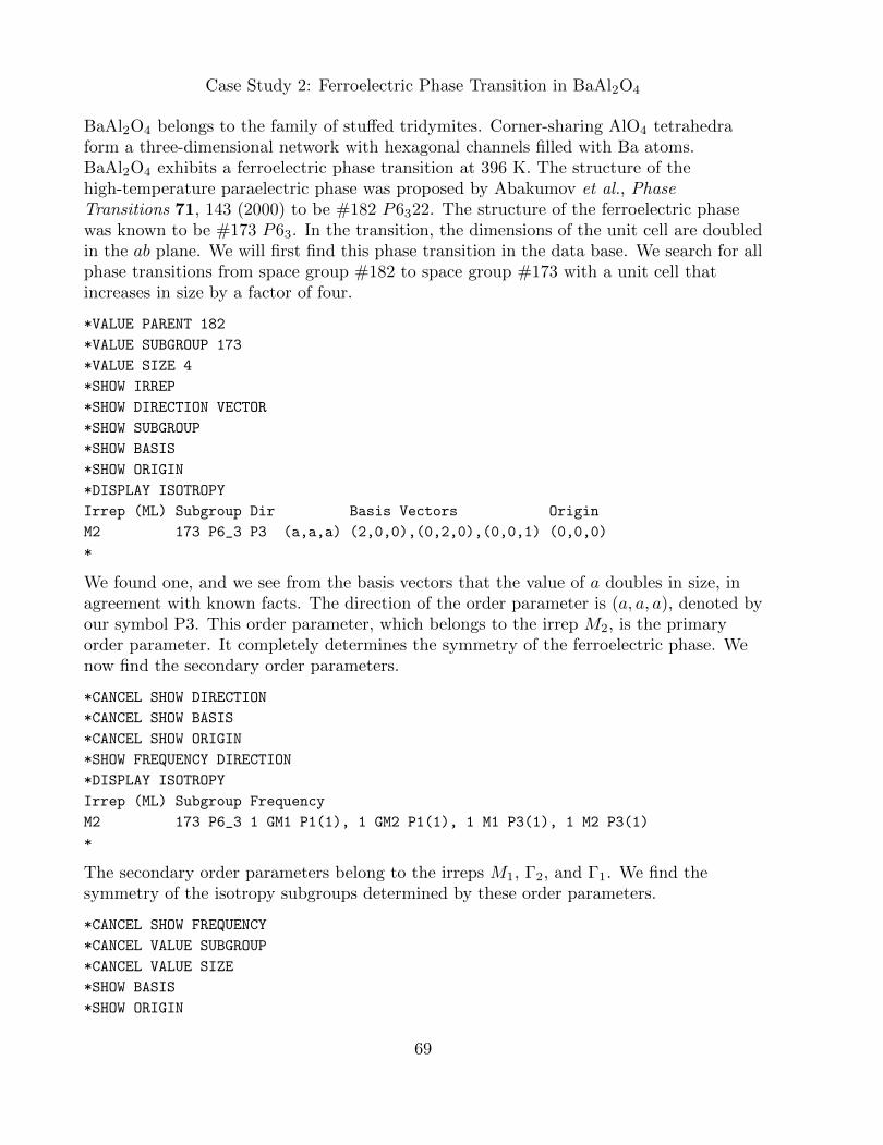
Case Study 2: Ferroelectric Phase Transition in BaAl2O4
BaAl2O4 belongs to the family of stuffed tridymites. Corner-sharing AlO4 tetrahedraform a three-dimensional network with hexagonal channels filled with Ba atoms.BaAl2O4 exhibits a ferroelectric phase transition at 396 K. The structure of thehigh-temperature paraelectric phase was proposed by Abakumov et al., PhaseTransitions 71, 143 (2000) to be #182 P6322. The structure of the ferroelectric phasewas known to be #173 P63. In the transition, the dimensions of the unit cell are doubledin the ab plane. We will first find this phase transition in the data base. We search for allphase transitions from space group #182 to space group #173 with a unit cell thatincreases in size by a factor of four.
*VALUE PARENT 182
*VALUE SUBGROUP 173
*VALUE SIZE 4
*SHOW IRREP
*SHOW DIRECTION VECTOR
*SHOW SUBGROUP
*SHOW BASIS
*SHOW ORIGIN
*DISPLAY ISOTROPY
Irrep (ML) Subgroup Dir Basis Vectors Origin
M2 173 P6_3 P3 (a,a,a) (2,0,0),(0,2,0),(0,0,1) (0,0,0)
*
We found one, and we see from the basis vectors that the value of a doubles in size, inagreement with known facts. The direction of the order parameter is (a, a, a), denoted byour symbol P3. This order parameter, which belongs to the irrep M2, is the primaryorder parameter. It completely determines the symmetry of the ferroelectric phase. Wenow find the secondary order parameters.
*CANCEL SHOW DIRECTION
*CANCEL SHOW BASIS
*CANCEL SHOW ORIGIN
*SHOW FREQUENCY DIRECTION
*DISPLAY ISOTROPY
Irrep (ML) Subgroup Frequency
M2 173 P6_3 1 GM1 P1(1), 1 GM2 P1(1), 1 M1 P3(1), 1 M2 P3(1)
*
The secondary order parameters belong to the irreps M1, Γ2, and Γ1. We find thesymmetry of the isotropy subgroups determined by these order parameters.
*CANCEL SHOW FREQUENCY
*CANCEL VALUE SUBGROUP
*CANCEL VALUE SIZE
*SHOW BASIS
*SHOW ORIGIN
69
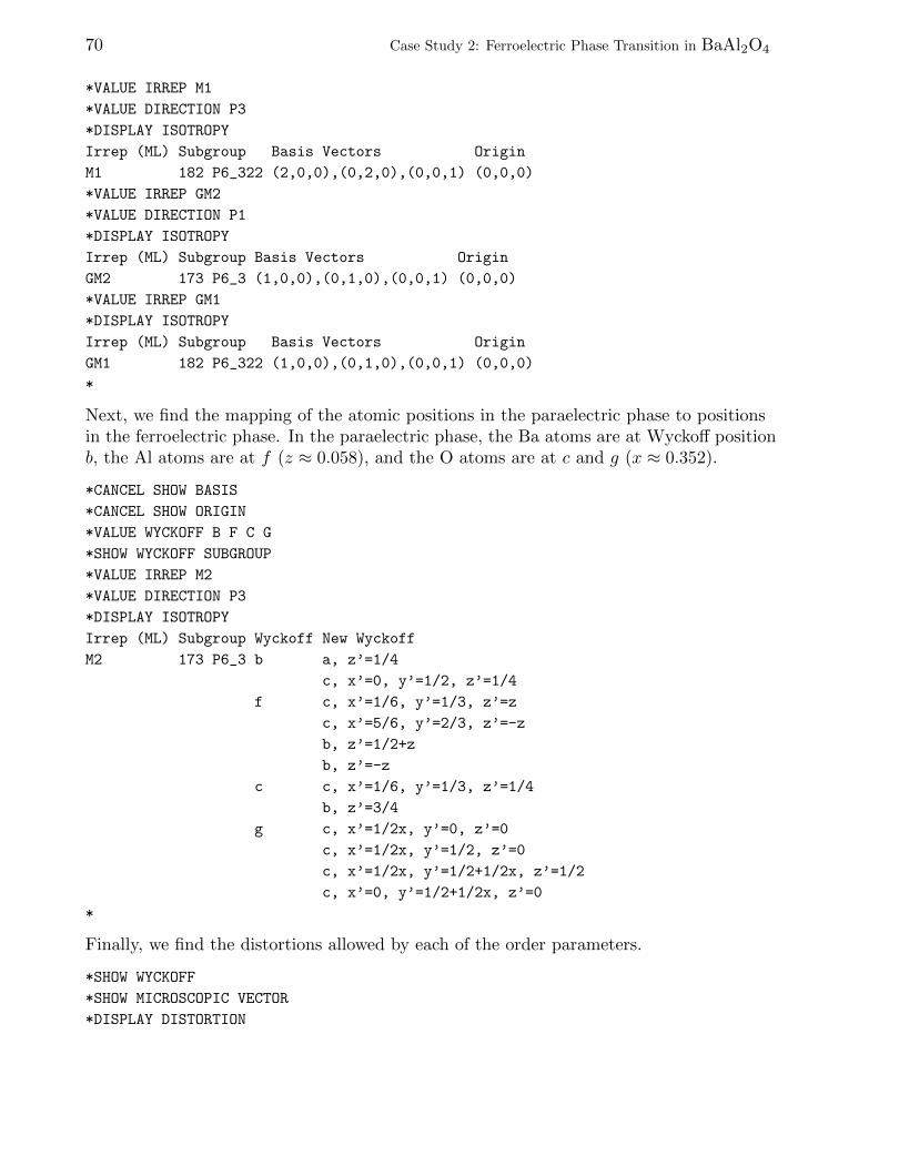
70 Case Study 2: Ferroelectric Phase Transition in BaAl2O4
*VALUE IRREP M1
*VALUE DIRECTION P3
*DISPLAY ISOTROPY
Irrep (ML) Subgroup Basis Vectors Origin
M1 182 P6_322 (2,0,0),(0,2,0),(0,0,1) (0,0,0)
*VALUE IRREP GM2
*VALUE DIRECTION P1
*DISPLAY ISOTROPY
Irrep (ML) Subgroup Basis Vectors Origin
GM2 173 P6_3 (1,0,0),(0,1,0),(0,0,1) (0,0,0)
*VALUE IRREP GM1
*DISPLAY ISOTROPY
Irrep (ML) Subgroup Basis Vectors Origin
GM1 182 P6_322 (1,0,0),(0,1,0),(0,0,1) (0,0,0)
*
Next, we find the mapping of the atomic positions in the paraelectric phase to positionsin the ferroelectric phase. In the paraelectric phase, the Ba atoms are at Wyckoff positionb, the Al atoms are at f (z ≈ 0.058), and the O atoms are at c and g (x ≈ 0.352).
*CANCEL SHOW BASIS
*CANCEL SHOW ORIGIN
*VALUE WYCKOFF B F C G
*SHOW WYCKOFF SUBGROUP
*VALUE IRREP M2
*VALUE DIRECTION P3
*DISPLAY ISOTROPY
Irrep (ML) Subgroup Wyckoff New Wyckoff
M2 173 P6_3 b a, z’=1/4
c, x’=0, y’=1/2, z’=1/4
f c, x’=1/6, y’=1/3, z’=z
c, x’=5/6, y’=2/3, z’=-z
b, z’=1/2+z
b, z’=-z
c c, x’=1/6, y’=1/3, z’=1/4
b, z’=3/4
g c, x’=1/2x, y’=0, z’=0
c, x’=1/2x, y’=1/2, z’=0
c, x’=1/2x, y’=1/2+1/2x, z’=1/2
c, x’=0, y’=1/2+1/2x, z’=0
*
Finally, we find the distortions allowed by each of the order parameters.
*SHOW WYCKOFF
*SHOW MICROSCOPIC VECTOR
*DISPLAY DISTORTION
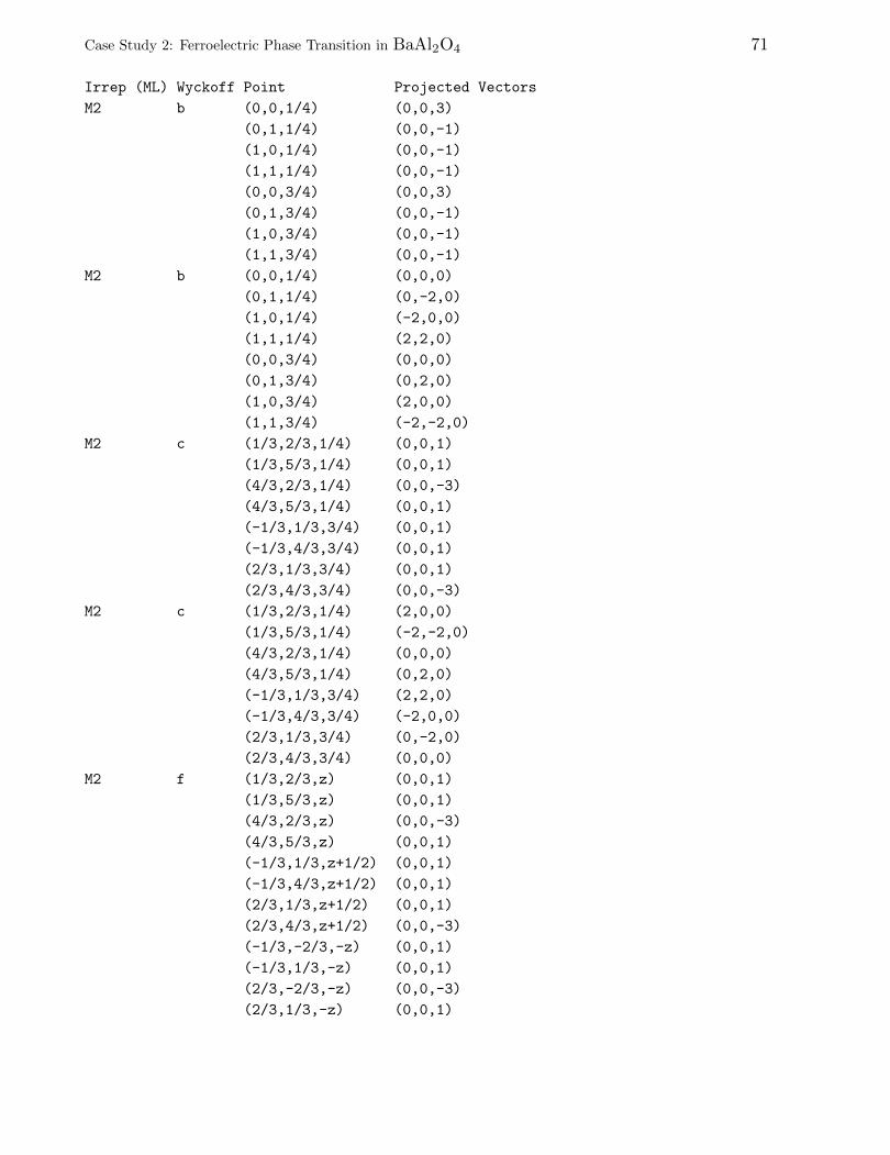
Case Study 2: Ferroelectric Phase Transition in BaAl2O4 71
Irrep (ML) Wyckoff Point Projected Vectors
M2 b (0,0,1/4) (0,0,3)
(0,1,1/4) (0,0,-1)
(1,0,1/4) (0,0,-1)
(1,1,1/4) (0,0,-1)
(0,0,3/4) (0,0,3)
(0,1,3/4) (0,0,-1)
(1,0,3/4) (0,0,-1)
(1,1,3/4) (0,0,-1)
M2 b (0,0,1/4) (0,0,0)
(0,1,1/4) (0,-2,0)
(1,0,1/4) (-2,0,0)
(1,1,1/4) (2,2,0)
(0,0,3/4) (0,0,0)
(0,1,3/4) (0,2,0)
(1,0,3/4) (2,0,0)
(1,1,3/4) (-2,-2,0)
M2 c (1/3,2/3,1/4) (0,0,1)
(1/3,5/3,1/4) (0,0,1)
(4/3,2/3,1/4) (0,0,-3)
(4/3,5/3,1/4) (0,0,1)
(-1/3,1/3,3/4) (0,0,1)
(-1/3,4/3,3/4) (0,0,1)
(2/3,1/3,3/4) (0,0,1)
(2/3,4/3,3/4) (0,0,-3)
M2 c (1/3,2/3,1/4) (2,0,0)
(1/3,5/3,1/4) (-2,-2,0)
(4/3,2/3,1/4) (0,0,0)
(4/3,5/3,1/4) (0,2,0)
(-1/3,1/3,3/4) (2,2,0)
(-1/3,4/3,3/4) (-2,0,0)
(2/3,1/3,3/4) (0,-2,0)
(2/3,4/3,3/4) (0,0,0)
M2 f (1/3,2/3,z) (0,0,1)
(1/3,5/3,z) (0,0,1)
(4/3,2/3,z) (0,0,-3)
(4/3,5/3,z) (0,0,1)
(-1/3,1/3,z+1/2) (0,0,1)
(-1/3,4/3,z+1/2) (0,0,1)
(2/3,1/3,z+1/2) (0,0,1)
(2/3,4/3,z+1/2) (0,0,-3)
(-1/3,-2/3,-z) (0,0,1)
(-1/3,1/3,-z) (0,0,1)
(2/3,-2/3,-z) (0,0,-3)
(2/3,1/3,-z) (0,0,1)
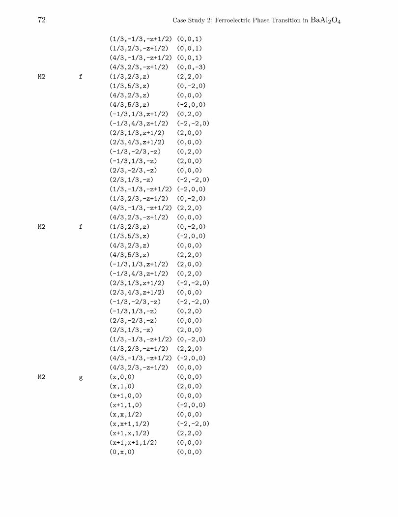
72 Case Study 2: Ferroelectric Phase Transition in BaAl2O4
(1/3,-1/3,-z+1/2) (0,0,1)
(1/3,2/3,-z+1/2) (0,0,1)
(4/3,-1/3,-z+1/2) (0,0,1)
(4/3,2/3,-z+1/2) (0,0,-3)
M2 f (1/3,2/3,z) (2,2,0)
(1/3,5/3,z) (0,-2,0)
(4/3,2/3,z) (0,0,0)
(4/3,5/3,z) (-2,0,0)
(-1/3,1/3,z+1/2) (0,2,0)
(-1/3,4/3,z+1/2) (-2,-2,0)
(2/3,1/3,z+1/2) (2,0,0)
(2/3,4/3,z+1/2) (0,0,0)
(-1/3,-2/3,-z) (0,2,0)
(-1/3,1/3,-z) (2,0,0)
(2/3,-2/3,-z) (0,0,0)
(2/3,1/3,-z) (-2,-2,0)
(1/3,-1/3,-z+1/2) (-2,0,0)
(1/3,2/3,-z+1/2) (0,-2,0)
(4/3,-1/3,-z+1/2) (2,2,0)
(4/3,2/3,-z+1/2) (0,0,0)
M2 f (1/3,2/3,z) (0,-2,0)
(1/3,5/3,z) (-2,0,0)
(4/3,2/3,z) (0,0,0)
(4/3,5/3,z) (2,2,0)
(-1/3,1/3,z+1/2) (2,0,0)
(-1/3,4/3,z+1/2) (0,2,0)
(2/3,1/3,z+1/2) (-2,-2,0)
(2/3,4/3,z+1/2) (0,0,0)
(-1/3,-2/3,-z) (-2,-2,0)
(-1/3,1/3,-z) (0,2,0)
(2/3,-2/3,-z) (0,0,0)
(2/3,1/3,-z) (2,0,0)
(1/3,-1/3,-z+1/2) (0,-2,0)
(1/3,2/3,-z+1/2) (2,2,0)
(4/3,-1/3,-z+1/2) (-2,0,0)
(4/3,2/3,-z+1/2) (0,0,0)
M2 g (x,0,0) (0,0,0)
(x,1,0) (2,0,0)
(x+1,0,0) (0,0,0)
(x+1,1,0) (-2,0,0)
(x,x,1/2) (0,0,0)
(x,x+1,1/2) (-2,-2,0)
(x+1,x,1/2) (2,2,0)
(x+1,x+1,1/2) (0,0,0)
(0,x,0) (0,0,0)
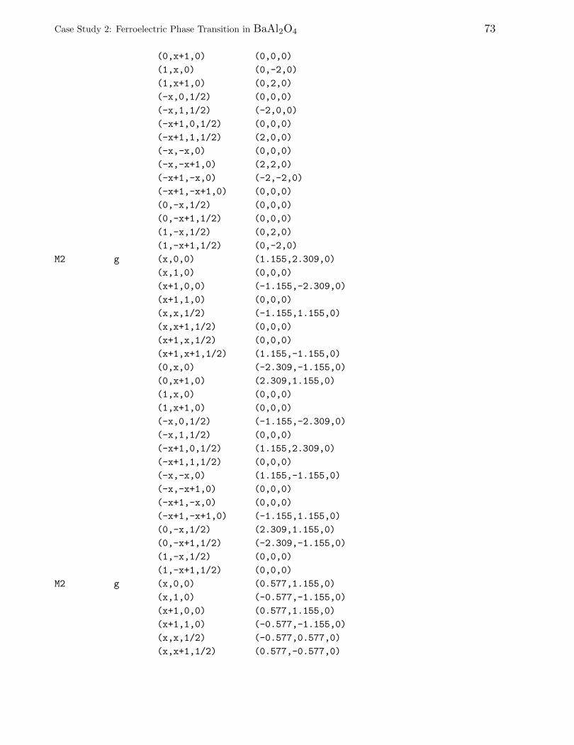
Case Study 2: Ferroelectric Phase Transition in BaAl2O4 73
(0,x+1,0) (0,0,0)
(1,x,0) (0,-2,0)
(1,x+1,0) (0,2,0)
(-x,0,1/2) (0,0,0)
(-x,1,1/2) (-2,0,0)
(-x+1,0,1/2) (0,0,0)
(-x+1,1,1/2) (2,0,0)
(-x,-x,0) (0,0,0)
(-x,-x+1,0) (2,2,0)
(-x+1,-x,0) (-2,-2,0)
(-x+1,-x+1,0) (0,0,0)
(0,-x,1/2) (0,0,0)
(0,-x+1,1/2) (0,0,0)
(1,-x,1/2) (0,2,0)
(1,-x+1,1/2) (0,-2,0)
M2 g (x,0,0) (1.155,2.309,0)
(x,1,0) (0,0,0)
(x+1,0,0) (-1.155,-2.309,0)
(x+1,1,0) (0,0,0)
(x,x,1/2) (-1.155,1.155,0)
(x,x+1,1/2) (0,0,0)
(x+1,x,1/2) (0,0,0)
(x+1,x+1,1/2) (1.155,-1.155,0)
(0,x,0) (-2.309,-1.155,0)
(0,x+1,0) (2.309,1.155,0)
(1,x,0) (0,0,0)
(1,x+1,0) (0,0,0)
(-x,0,1/2) (-1.155,-2.309,0)
(-x,1,1/2) (0,0,0)
(-x+1,0,1/2) (1.155,2.309,0)
(-x+1,1,1/2) (0,0,0)
(-x,-x,0) (1.155,-1.155,0)
(-x,-x+1,0) (0,0,0)
(-x+1,-x,0) (0,0,0)
(-x+1,-x+1,0) (-1.155,1.155,0)
(0,-x,1/2) (2.309,1.155,0)
(0,-x+1,1/2) (-2.309,-1.155,0)
(1,-x,1/2) (0,0,0)
(1,-x+1,1/2) (0,0,0)
M2 g (x,0,0) (0.577,1.155,0)
(x,1,0) (-0.577,-1.155,0)
(x+1,0,0) (0.577,1.155,0)
(x+1,1,0) (-0.577,-1.155,0)
(x,x,1/2) (-0.577,0.577,0)
(x,x+1,1/2) (0.577,-0.577,0)
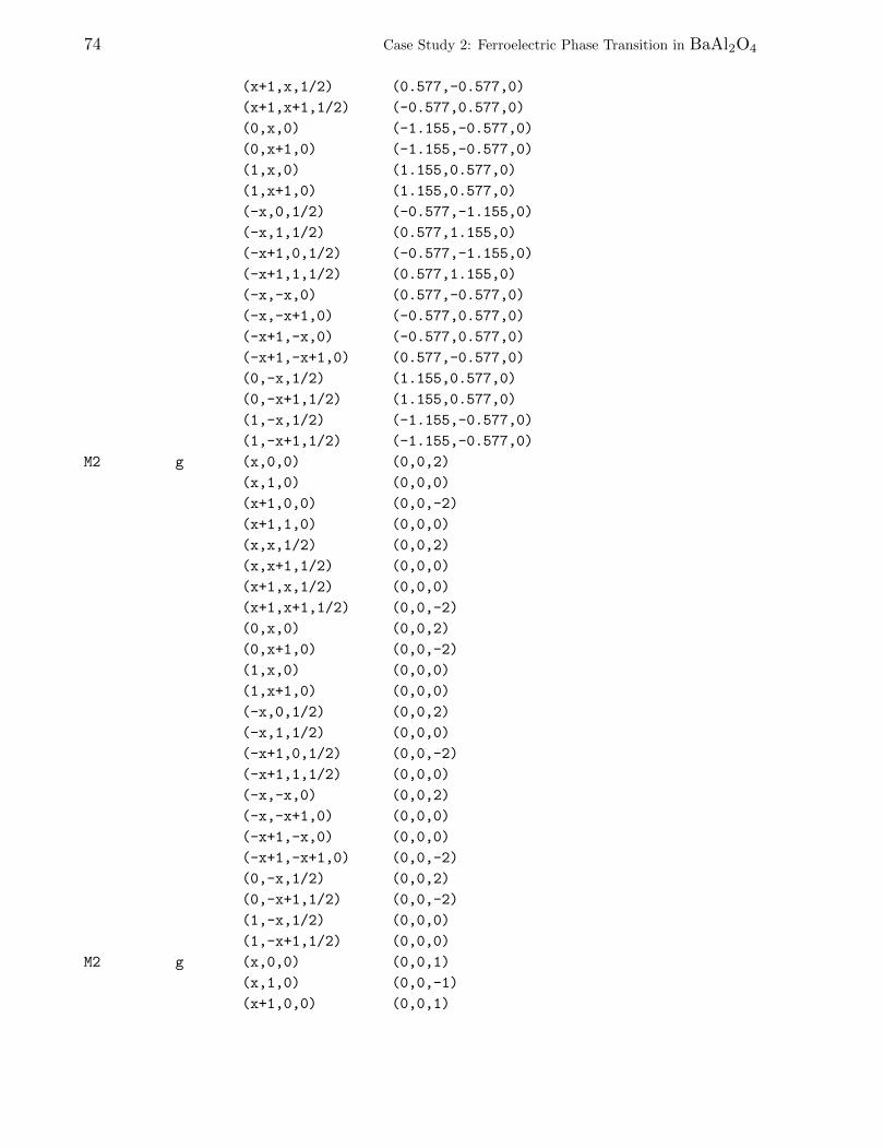
74 Case Study 2: Ferroelectric Phase Transition in BaAl2O4
(x+1,x,1/2) (0.577,-0.577,0)
(x+1,x+1,1/2) (-0.577,0.577,0)
(0,x,0) (-1.155,-0.577,0)
(0,x+1,0) (-1.155,-0.577,0)
(1,x,0) (1.155,0.577,0)
(1,x+1,0) (1.155,0.577,0)
(-x,0,1/2) (-0.577,-1.155,0)
(-x,1,1/2) (0.577,1.155,0)
(-x+1,0,1/2) (-0.577,-1.155,0)
(-x+1,1,1/2) (0.577,1.155,0)
(-x,-x,0) (0.577,-0.577,0)
(-x,-x+1,0) (-0.577,0.577,0)
(-x+1,-x,0) (-0.577,0.577,0)
(-x+1,-x+1,0) (0.577,-0.577,0)
(0,-x,1/2) (1.155,0.577,0)
(0,-x+1,1/2) (1.155,0.577,0)
(1,-x,1/2) (-1.155,-0.577,0)
(1,-x+1,1/2) (-1.155,-0.577,0)
M2 g (x,0,0) (0,0,2)
(x,1,0) (0,0,0)
(x+1,0,0) (0,0,-2)
(x+1,1,0) (0,0,0)
(x,x,1/2) (0,0,2)
(x,x+1,1/2) (0,0,0)
(x+1,x,1/2) (0,0,0)
(x+1,x+1,1/2) (0,0,-2)
(0,x,0) (0,0,2)
(0,x+1,0) (0,0,-2)
(1,x,0) (0,0,0)
(1,x+1,0) (0,0,0)
(-x,0,1/2) (0,0,2)
(-x,1,1/2) (0,0,0)
(-x+1,0,1/2) (0,0,-2)
(-x+1,1,1/2) (0,0,0)
(-x,-x,0) (0,0,2)
(-x,-x+1,0) (0,0,0)
(-x+1,-x,0) (0,0,0)
(-x+1,-x+1,0) (0,0,-2)
(0,-x,1/2) (0,0,2)
(0,-x+1,1/2) (0,0,-2)
(1,-x,1/2) (0,0,0)
(1,-x+1,1/2) (0,0,0)
M2 g (x,0,0) (0,0,1)
(x,1,0) (0,0,-1)
(x+1,0,0) (0,0,1)
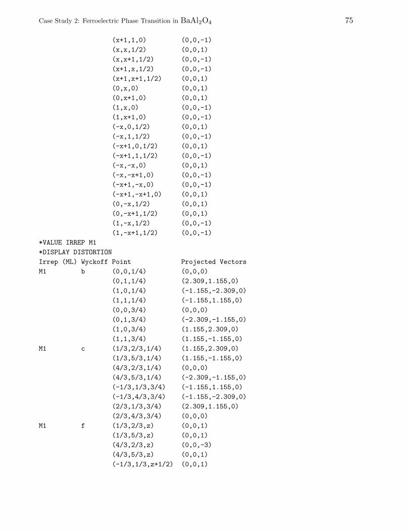
Case Study 2: Ferroelectric Phase Transition in BaAl2O4 75
(x+1,1,0) (0,0,-1)
(x,x,1/2) (0,0,1)
(x,x+1,1/2) (0,0,-1)
(x+1,x,1/2) (0,0,-1)
(x+1,x+1,1/2) (0,0,1)
(0,x,0) (0,0,1)
(0,x+1,0) (0,0,1)
(1,x,0) (0,0,-1)
(1,x+1,0) (0,0,-1)
(-x,0,1/2) (0,0,1)
(-x,1,1/2) (0,0,-1)
(-x+1,0,1/2) (0,0,1)
(-x+1,1,1/2) (0,0,-1)
(-x,-x,0) (0,0,1)
(-x,-x+1,0) (0,0,-1)
(-x+1,-x,0) (0,0,-1)
(-x+1,-x+1,0) (0,0,1)
(0,-x,1/2) (0,0,1)
(0,-x+1,1/2) (0,0,1)
(1,-x,1/2) (0,0,-1)
(1,-x+1,1/2) (0,0,-1)
*VALUE IRREP M1
*DISPLAY DISTORTION
Irrep (ML) Wyckoff Point Projected Vectors
M1 b (0,0,1/4) (0,0,0)
(0,1,1/4) (2.309,1.155,0)
(1,0,1/4) (-1.155,-2.309,0)
(1,1,1/4) (-1.155,1.155,0)
(0,0,3/4) (0,0,0)
(0,1,3/4) (-2.309,-1.155,0)
(1,0,3/4) (1.155,2.309,0)
(1,1,3/4) (1.155,-1.155,0)
M1 c (1/3,2/3,1/4) (1.155,2.309,0)
(1/3,5/3,1/4) (1.155,-1.155,0)
(4/3,2/3,1/4) (0,0,0)
(4/3,5/3,1/4) (-2.309,-1.155,0)
(-1/3,1/3,3/4) (-1.155,1.155,0)
(-1/3,4/3,3/4) (-1.155,-2.309,0)
(2/3,1/3,3/4) (2.309,1.155,0)
(2/3,4/3,3/4) (0,0,0)
M1 f (1/3,2/3,z) (0,0,1)
(1/3,5/3,z) (0,0,1)
(4/3,2/3,z) (0,0,-3)
(4/3,5/3,z) (0,0,1)
(-1/3,1/3,z+1/2) (0,0,1)
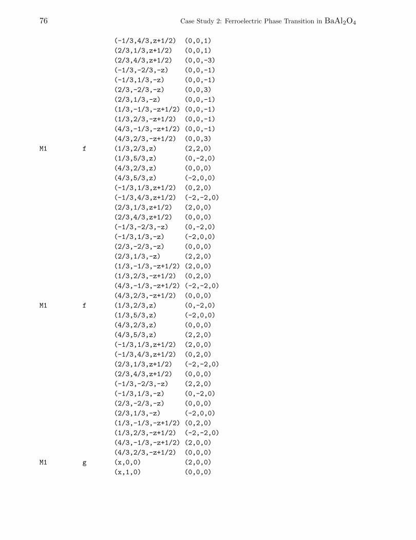
76 Case Study 2: Ferroelectric Phase Transition in BaAl2O4
(-1/3,4/3,z+1/2) (0,0,1)
(2/3,1/3,z+1/2) (0,0,1)
(2/3,4/3,z+1/2) (0,0,-3)
(-1/3,-2/3,-z) (0,0,-1)
(-1/3,1/3,-z) (0,0,-1)
(2/3,-2/3,-z) (0,0,3)
(2/3,1/3,-z) (0,0,-1)
(1/3,-1/3,-z+1/2) (0,0,-1)
(1/3,2/3,-z+1/2) (0,0,-1)
(4/3,-1/3,-z+1/2) (0,0,-1)
(4/3,2/3,-z+1/2) (0,0,3)
M1 f (1/3,2/3,z) (2,2,0)
(1/3,5/3,z) (0,-2,0)
(4/3,2/3,z) (0,0,0)
(4/3,5/3,z) (-2,0,0)
(-1/3,1/3,z+1/2) (0,2,0)
(-1/3,4/3,z+1/2) (-2,-2,0)
(2/3,1/3,z+1/2) (2,0,0)
(2/3,4/3,z+1/2) (0,0,0)
(-1/3,-2/3,-z) (0,-2,0)
(-1/3,1/3,-z) (-2,0,0)
(2/3,-2/3,-z) (0,0,0)
(2/3,1/3,-z) (2,2,0)
(1/3,-1/3,-z+1/2) (2,0,0)
(1/3,2/3,-z+1/2) (0,2,0)
(4/3,-1/3,-z+1/2) (-2,-2,0)
(4/3,2/3,-z+1/2) (0,0,0)
M1 f (1/3,2/3,z) (0,-2,0)
(1/3,5/3,z) (-2,0,0)
(4/3,2/3,z) (0,0,0)
(4/3,5/3,z) (2,2,0)
(-1/3,1/3,z+1/2) (2,0,0)
(-1/3,4/3,z+1/2) (0,2,0)
(2/3,1/3,z+1/2) (-2,-2,0)
(2/3,4/3,z+1/2) (0,0,0)
(-1/3,-2/3,-z) (2,2,0)
(-1/3,1/3,-z) (0,-2,0)
(2/3,-2/3,-z) (0,0,0)
(2/3,1/3,-z) (-2,0,0)
(1/3,-1/3,-z+1/2) (0,2,0)
(1/3,2/3,-z+1/2) (-2,-2,0)
(4/3,-1/3,-z+1/2) (2,0,0)
(4/3,2/3,-z+1/2) (0,0,0)
M1 g (x,0,0) (2,0,0)
(x,1,0) (0,0,0)
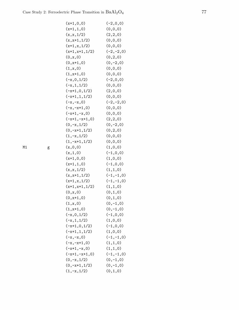
Case Study 2: Ferroelectric Phase Transition in BaAl2O4 77
(x+1,0,0) (-2,0,0)
(x+1,1,0) (0,0,0)
(x,x,1/2) (2,2,0)
(x,x+1,1/2) (0,0,0)
(x+1,x,1/2) (0,0,0)
(x+1,x+1,1/2) (-2,-2,0)
(0,x,0) (0,2,0)
(0,x+1,0) (0,-2,0)
(1,x,0) (0,0,0)
(1,x+1,0) (0,0,0)
(-x,0,1/2) (-2,0,0)
(-x,1,1/2) (0,0,0)
(-x+1,0,1/2) (2,0,0)
(-x+1,1,1/2) (0,0,0)
(-x,-x,0) (-2,-2,0)
(-x,-x+1,0) (0,0,0)
(-x+1,-x,0) (0,0,0)
(-x+1,-x+1,0) (2,2,0)
(0,-x,1/2) (0,-2,0)
(0,-x+1,1/2) (0,2,0)
(1,-x,1/2) (0,0,0)
(1,-x+1,1/2) (0,0,0)
M1 g (x,0,0) (1,0,0)
(x,1,0) (-1,0,0)
(x+1,0,0) (1,0,0)
(x+1,1,0) (-1,0,0)
(x,x,1/2) (1,1,0)
(x,x+1,1/2) (-1,-1,0)
(x+1,x,1/2) (-1,-1,0)
(x+1,x+1,1/2) (1,1,0)
(0,x,0) (0,1,0)
(0,x+1,0) (0,1,0)
(1,x,0) (0,-1,0)
(1,x+1,0) (0,-1,0)
(-x,0,1/2) (-1,0,0)
(-x,1,1/2) (1,0,0)
(-x+1,0,1/2) (-1,0,0)
(-x+1,1,1/2) (1,0,0)
(-x,-x,0) (-1,-1,0)
(-x,-x+1,0) (1,1,0)
(-x+1,-x,0) (1,1,0)
(-x+1,-x+1,0) (-1,-1,0)
(0,-x,1/2) (0,-1,0)
(0,-x+1,1/2) (0,-1,0)
(1,-x,1/2) (0,1,0)
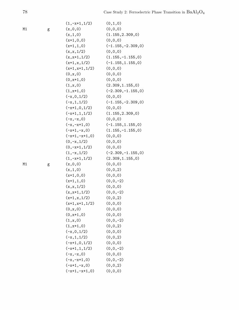
78 Case Study 2: Ferroelectric Phase Transition in BaAl2O4
(1,-x+1,1/2) (0,1,0)
M1 g (x,0,0) (0,0,0)
(x,1,0) (1.155,2.309,0)
(x+1,0,0) (0,0,0)
(x+1,1,0) (-1.155,-2.309,0)
(x,x,1/2) (0,0,0)
(x,x+1,1/2) (1.155,-1.155,0)
(x+1,x,1/2) (-1.155,1.155,0)
(x+1,x+1,1/2) (0,0,0)
(0,x,0) (0,0,0)
(0,x+1,0) (0,0,0)
(1,x,0) (2.309,1.155,0)
(1,x+1,0) (-2.309,-1.155,0)
(-x,0,1/2) (0,0,0)
(-x,1,1/2) (-1.155,-2.309,0)
(-x+1,0,1/2) (0,0,0)
(-x+1,1,1/2) (1.155,2.309,0)
(-x,-x,0) (0,0,0)
(-x,-x+1,0) (-1.155,1.155,0)
(-x+1,-x,0) (1.155,-1.155,0)
(-x+1,-x+1,0) (0,0,0)
(0,-x,1/2) (0,0,0)
(0,-x+1,1/2) (0,0,0)
(1,-x,1/2) (-2.309,-1.155,0)
(1,-x+1,1/2) (2.309,1.155,0)
M1 g (x,0,0) (0,0,0)
(x,1,0) (0,0,2)
(x+1,0,0) (0,0,0)
(x+1,1,0) (0,0,-2)
(x,x,1/2) (0,0,0)
(x,x+1,1/2) (0,0,-2)
(x+1,x,1/2) (0,0,2)
(x+1,x+1,1/2) (0,0,0)
(0,x,0) (0,0,0)
(0,x+1,0) (0,0,0)
(1,x,0) (0,0,-2)
(1,x+1,0) (0,0,2)
(-x,0,1/2) (0,0,0)
(-x,1,1/2) (0,0,2)
(-x+1,0,1/2) (0,0,0)
(-x+1,1,1/2) (0,0,-2)
(-x,-x,0) (0,0,0)
(-x,-x+1,0) (0,0,-2)
(-x+1,-x,0) (0,0,2)
(-x+1,-x+1,0) (0,0,0)
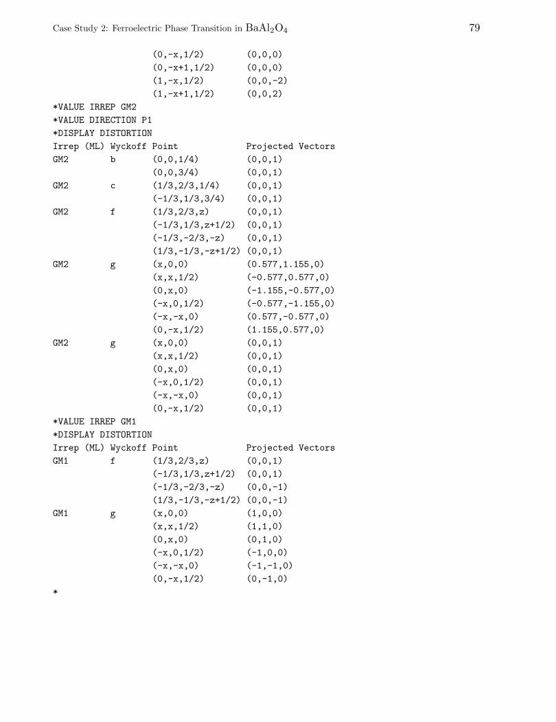
Case Study 2: Ferroelectric Phase Transition in BaAl2O4 79
(0,-x,1/2) (0,0,0)
(0,-x+1,1/2) (0,0,0)
(1,-x,1/2) (0,0,-2)
(1,-x+1,1/2) (0,0,2)
*VALUE IRREP GM2
*VALUE DIRECTION P1
*DISPLAY DISTORTION
Irrep (ML) Wyckoff Point Projected Vectors
GM2 b (0,0,1/4) (0,0,1)
(0,0,3/4) (0,0,1)
GM2 c (1/3,2/3,1/4) (0,0,1)
(-1/3,1/3,3/4) (0,0,1)
GM2 f (1/3,2/3,z) (0,0,1)
(-1/3,1/3,z+1/2) (0,0,1)
(-1/3,-2/3,-z) (0,0,1)
(1/3,-1/3,-z+1/2) (0,0,1)
GM2 g (x,0,0) (0.577,1.155,0)
(x,x,1/2) (-0.577,0.577,0)
(0,x,0) (-1.155,-0.577,0)
(-x,0,1/2) (-0.577,-1.155,0)
(-x,-x,0) (0.577,-0.577,0)
(0,-x,1/2) (1.155,0.577,0)
GM2 g (x,0,0) (0,0,1)
(x,x,1/2) (0,0,1)
(0,x,0) (0,0,1)
(-x,0,1/2) (0,0,1)
(-x,-x,0) (0,0,1)
(0,-x,1/2) (0,0,1)
*VALUE IRREP GM1
*DISPLAY DISTORTION
Irrep (ML) Wyckoff Point Projected Vectors
GM1 f (1/3,2/3,z) (0,0,1)
(-1/3,1/3,z+1/2) (0,0,1)
(-1/3,-2/3,-z) (0,0,-1)
(1/3,-1/3,-z+1/2) (0,0,-1)
GM1 g (x,0,0) (1,0,0)
(x,x,1/2) (1,1,0)
(0,x,0) (0,1,0)
(-x,0,1/2) (-1,0,0)
(-x,-x,0) (-1,-1,0)
(0,-x,1/2) (0,-1,0)
*
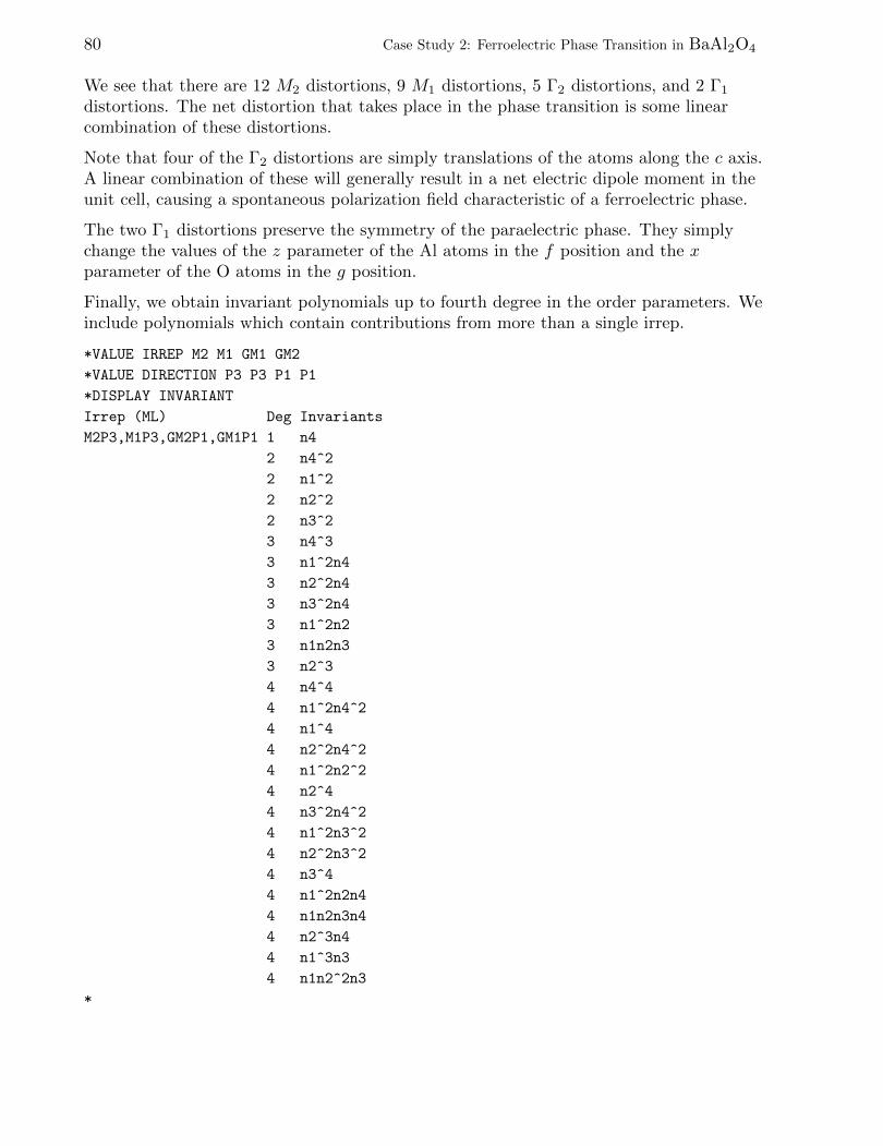
80 Case Study 2: Ferroelectric Phase Transition in BaAl2O4
We see that there are 12 M2 distortions, 9 M1 distortions, 5 Γ2 distortions, and 2 Γ1
distortions. The net distortion that takes place in the phase transition is some linearcombination of these distortions.
Note that four of the Γ2 distortions are simply translations of the atoms along the c axis.A linear combination of these will generally result in a net electric dipole moment in theunit cell, causing a spontaneous polarization field characteristic of a ferroelectric phase.
The two Γ1 distortions preserve the symmetry of the paraelectric phase. They simplychange the values of the z parameter of the Al atoms in the f position and the xparameter of the O atoms in the g position.
Finally, we obtain invariant polynomials up to fourth degree in the order parameters. Weinclude polynomials which contain contributions from more than a single irrep.
*VALUE IRREP M2 M1 GM1 GM2
*VALUE DIRECTION P3 P3 P1 P1
*DISPLAY INVARIANT
Irrep (ML) Deg Invariants
M2P3,M1P3,GM2P1,GM1P1 1 n4
2 n4^2
2 n1^2
2 n2^2
2 n3^2
3 n4^3
3 n1^2n4
3 n2^2n4
3 n3^2n4
3 n1^2n2
3 n1n2n3
3 n2^3
4 n4^4
4 n1^2n4^2
4 n1^4
4 n2^2n4^2
4 n1^2n2^2
4 n2^4
4 n3^2n4^2
4 n1^2n3^2
4 n2^2n3^2
4 n3^4
4 n1^2n2n4
4 n1n2n3n4
4 n2^3n4
4 n1^3n3
4 n1n2^2n3
*

Case Study 2: Ferroelectric Phase Transition in BaAl2O4 81
In the above results, η1, η2, η3, η4 refer to the order parameter (η1, η1, η1) for M2
(direction P3), the order parameter (η2, η2, η2) for M1 (direction P3), the orderparameter (η3) for Γ2, and the order parameter (η4) for Γ1, respectively. The form of theLandau free energy expanded in powers of the order parameters is simply a linearcombination of the above polynomials.
This is the end of this case study. You may exit the program:
*QUIT

82 Case Study 2: Ferroelectric Phase Transition in BaAl2O4
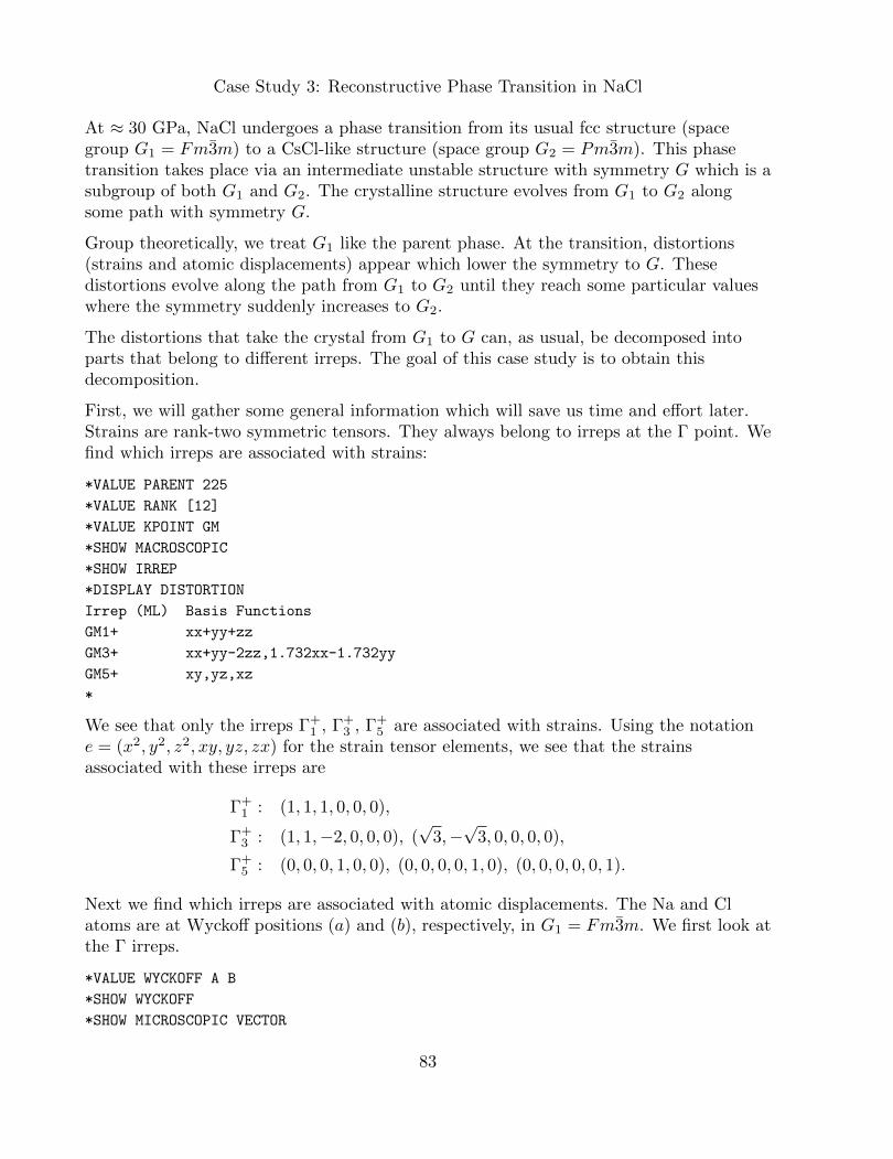
Case Study 3: Reconstructive Phase Transition in NaCl
At ≈ 30 GPa, NaCl undergoes a phase transition from its usual fcc structure (spacegroup G1 = Fm3m) to a CsCl-like structure (space group G2 = Pm3m). This phasetransition takes place via an intermediate unstable structure with symmetry G which is asubgroup of both G1 and G2. The crystalline structure evolves from G1 to G2 alongsome path with symmetry G.
Group theoretically, we treat G1 like the parent phase. At the transition, distortions(strains and atomic displacements) appear which lower the symmetry to G. Thesedistortions evolve along the path from G1 to G2 until they reach some particular valueswhere the symmetry suddenly increases to G2.
The distortions that take the crystal from G1 to G can, as usual, be decomposed intoparts that belong to different irreps. The goal of this case study is to obtain thisdecomposition.
First, we will gather some general information which will save us time and effort later.Strains are rank-two symmetric tensors. They always belong to irreps at the Γ point. Wefind which irreps are associated with strains:
*VALUE PARENT 225
*VALUE RANK [12]
*VALUE KPOINT GM
*SHOW MACROSCOPIC
*SHOW IRREP
*DISPLAY DISTORTION
Irrep (ML) Basis Functions
GM1+ xx+yy+zz
GM3+ xx+yy-2zz,1.732xx-1.732yy
GM5+ xy,yz,xz
*
We see that only the irreps Γ+1 , Γ+
3 , Γ+5 are associated with strains. Using the notation
e = (x2, y2, z2, xy, yz, zx) for the strain tensor elements, we see that the strainsassociated with these irreps are
Γ+1 : (1, 1, 1, 0, 0, 0),
Γ+3 : (1, 1,−2, 0, 0, 0), (
√3,−√
3, 0, 0, 0, 0),
Γ+5 : (0, 0, 0, 1, 0, 0), (0, 0, 0, 0, 1, 0), (0, 0, 0, 0, 0, 1).
Next we find which irreps are associated with atomic displacements. The Na and Clatoms are at Wyckoff positions (a) and (b), respectively, in G1 = Fm3m. We first look atthe Γ irreps.
*VALUE WYCKOFF A B
*SHOW WYCKOFF
*SHOW MICROSCOPIC VECTOR
83
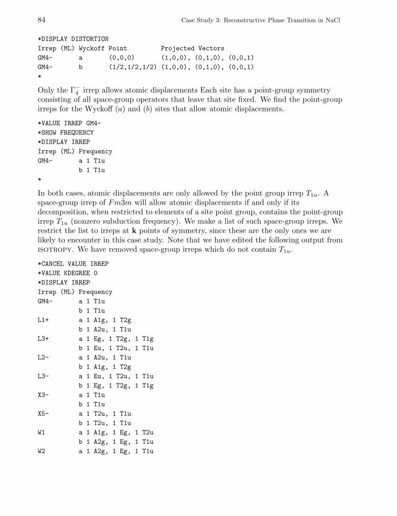
84 Case Study 3: Reconstructive Phase Transition in NaCl
*DISPLAY DISTORTION
Irrep (ML) Wyckoff Point Projected Vectors
GM4- a (0,0,0) (1,0,0), (0,1,0), (0,0,1)
GM4- b (1/2,1/2,1/2) (1,0,0), (0,1,0), (0,0,1)
*
Only the Γ−4 irrep allows atomic displacements Each site has a point-group symmetryconsisting of all space-group operators that leave that site fixed. We find the point-groupirreps for the Wyckoff (a) and (b) sites that allow atomic displacements.
*VALUE IRREP GM4-
*SHOW FREQUENCY
*DISPLAY IRREP
Irrep (ML) Frequency
GM4- a 1 T1u
b 1 T1u
*
In both cases, atomic displacements are only allowed by the point group irrep T1u. Aspace-group irrep of Fm3m will allow atomic displacements if and only if itsdecomposition, when restricted to elements of a site point group, contains the point-groupirrep T1u (nonzero subduction frequency). We make a list of such space-group irreps. Werestrict the list to irreps at k points of symmetry, since these are the only ones we arelikely to encounter in this case study. Note that we have edited the following output fromisotropy. We have removed space-group irreps which do not contain T1u.
*CANCEL VALUE IRREP
*VALUE KDEGREE 0
*DISPLAY IRREP
Irrep (ML) Frequency
GM4- a 1 T1u
b 1 T1u
L1+ a 1 A1g, 1 T2g
b 1 A2u, 1 T1u
L3+ a 1 Eg, 1 T2g, 1 T1g
b 1 Eu, 1 T2u, 1 T1u
L2- a 1 A2u, 1 T1u
b 1 A1g, 1 T2g
L3- a 1 Eu, 1 T2u, 1 T1u
b 1 Eg, 1 T2g, 1 T1g
X3- a 1 T1u
b 1 T1u
X5- a 1 T2u, 1 T1u
b 1 T2u, 1 T1u
W1 a 1 A1g, 1 Eg, 1 T2u
b 1 A2g, 1 Eg, 1 T1u
W2 a 1 A2g, 1 Eg, 1 T1u
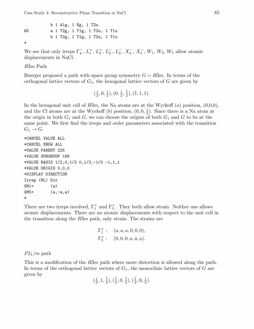
Case Study 3: Reconstructive Phase Transition in NaCl 85
b 1 A1g, 1 Eg, 1 T2u
W5 a 1 T2g, 1 T1g, 1 T2u, 1 T1u
b 1 T2g, 1 T1g, 1 T2u, 1 T1u
*
We see that only irreps Γ−4 , L+1 , L+
3 , L−2 , L−3 , X−3 , X−5 , W1, W2, W5 allow atomicdisplacements in NaCl.
R3m Path
Buerger proposed a path with space group symmetry G = R3m. In terms of theorthogonal lattice vectors of G1, the hexagonal lattice vectors of G are given by
( 12 , 0,
12 ), (0, 12 ,
12 ), (1, 1, 1).
In the hexagonal unit cell of R3m, the Na atoms are at the Wyckoff (a) position, (0,0,0),and the Cl atoms are at the Wyckoff (b) position, (0, 0, 12 ). Since there is a Na atom atthe origin in both G1 and G, we can choose the origins of both G1 and G to be at thesame point. We first find the irreps and order parameters associated with the transitionG1 → G.
*CANCEL VALUE ALL
*CANCEL SHOW ALL
*VALUE PARENT 225
*VALUE SUBGROUP 166
*VALUE BASIS 1/2,0,1/2 0,1/2,-1/2 -1,1,1
*VALUE ORIGIN 0,0,0
*DISPLAY DIRECTION
Irrep (ML) Dir
GM1+ (a)
GM5+ (a,-a,a)
*
There are two irreps involved, Γ+1 and Γ+
5 . They both allow strain. Neither one allowsatomic displacements. There are no atomic displacements with respect to the unit cell inthe transition along the R3m path, only strain. The strains are
Γ+1 : (a, a, a, 0, 0, 0),
Γ+5 : (0, 0, 0, a, a, a).
P21/m path
This is a modification of the R3m path where more distortion is allowed along the path.In terms of the orthogonal lattice vectors of G1, the monoclinic lattice vectors of G aregiven by
( 12 , 1,
12 ), ( 1
2 , 0,12 ), ( 1
2 , 0,12 ).
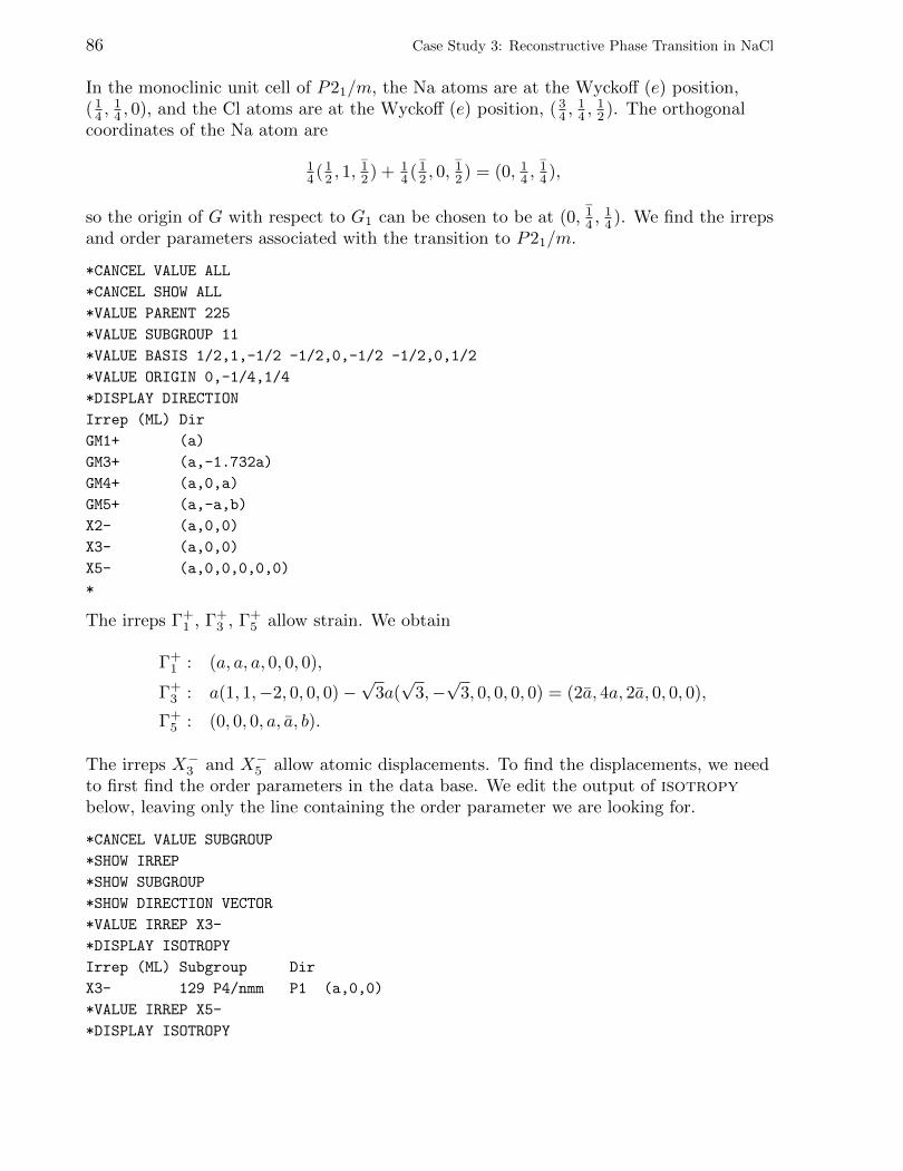
86 Case Study 3: Reconstructive Phase Transition in NaCl
In the monoclinic unit cell of P21/m, the Na atoms are at the Wyckoff (e) position,( 14 ,
14 , 0), and the Cl atoms are at the Wyckoff (e) position, ( 3
4 ,14 ,
12 ). The orthogonal
coordinates of the Na atom are
14 ( 1
2 , 1,12 ) + 1
4 ( 12 , 0,
12 ) = (0, 14 ,
14 ),
so the origin of G with respect to G1 can be chosen to be at (0, 14 ,14 ). We find the irreps
and order parameters associated with the transition to P21/m.
*CANCEL VALUE ALL
*CANCEL SHOW ALL
*VALUE PARENT 225
*VALUE SUBGROUP 11
*VALUE BASIS 1/2,1,-1/2 -1/2,0,-1/2 -1/2,0,1/2
*VALUE ORIGIN 0,-1/4,1/4
*DISPLAY DIRECTION
Irrep (ML) Dir
GM1+ (a)
GM3+ (a,-1.732a)
GM4+ (a,0,a)
GM5+ (a,-a,b)
X2- (a,0,0)
X3- (a,0,0)
X5- (a,0,0,0,0,0)
*
The irreps Γ+1 , Γ+
3 , Γ+5 allow strain. We obtain
Γ+1 : (a, a, a, 0, 0, 0),
Γ+3 : a(1, 1,−2, 0, 0, 0)−
√3a(√
3,−√
3, 0, 0, 0, 0) = (2a, 4a, 2a, 0, 0, 0),
Γ+5 : (0, 0, 0, a, a, b).
The irreps X−3 and X−5 allow atomic displacements. To find the displacements, we needto first find the order parameters in the data base. We edit the output of isotropybelow, leaving only the line containing the order parameter we are looking for.
*CANCEL VALUE SUBGROUP
*SHOW IRREP
*SHOW SUBGROUP
*SHOW DIRECTION VECTOR
*VALUE IRREP X3-
*DISPLAY ISOTROPY
Irrep (ML) Subgroup Dir
X3- 129 P4/nmm P1 (a,0,0)
*VALUE IRREP X5-
*DISPLAY ISOTROPY
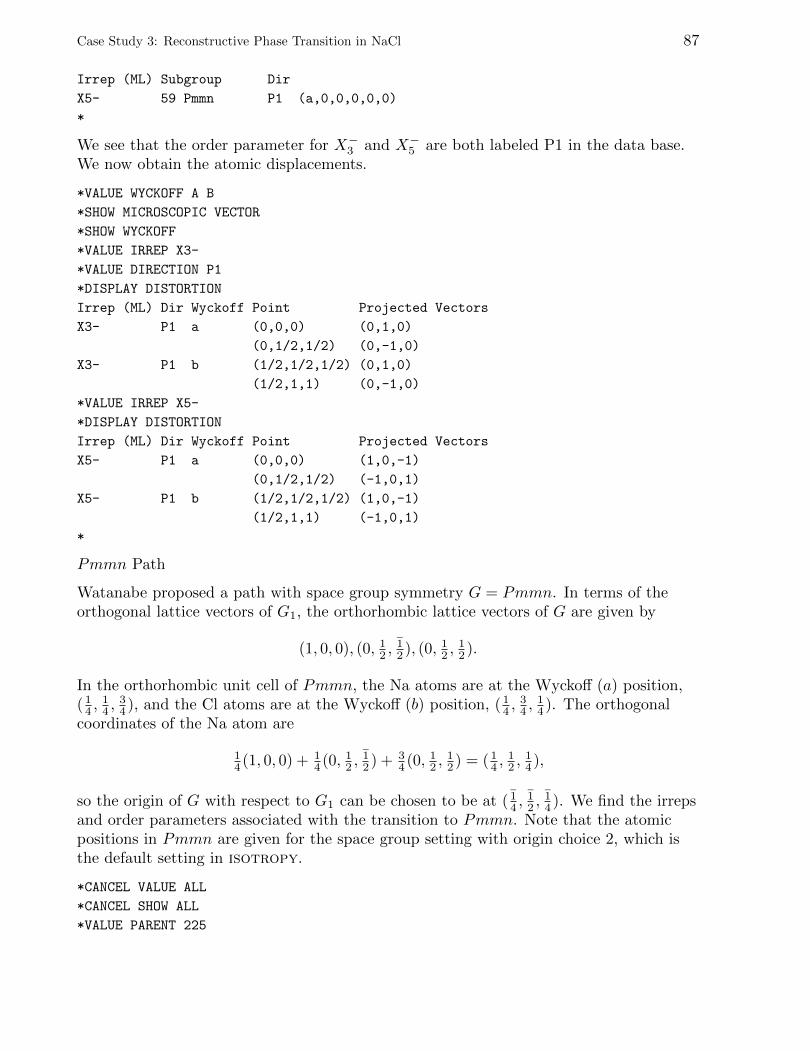
Case Study 3: Reconstructive Phase Transition in NaCl 87
Irrep (ML) Subgroup Dir
X5- 59 Pmmn P1 (a,0,0,0,0,0)
*
We see that the order parameter for X−3 and X−5 are both labeled P1 in the data base.We now obtain the atomic displacements.
*VALUE WYCKOFF A B
*SHOW MICROSCOPIC VECTOR
*SHOW WYCKOFF
*VALUE IRREP X3-
*VALUE DIRECTION P1
*DISPLAY DISTORTION
Irrep (ML) Dir Wyckoff Point Projected Vectors
X3- P1 a (0,0,0) (0,1,0)
(0,1/2,1/2) (0,-1,0)
X3- P1 b (1/2,1/2,1/2) (0,1,0)
(1/2,1,1) (0,-1,0)
*VALUE IRREP X5-
*DISPLAY DISTORTION
Irrep (ML) Dir Wyckoff Point Projected Vectors
X5- P1 a (0,0,0) (1,0,-1)
(0,1/2,1/2) (-1,0,1)
X5- P1 b (1/2,1/2,1/2) (1,0,-1)
(1/2,1,1) (-1,0,1)
*
Pmmn Path
Watanabe proposed a path with space group symmetry G = Pmmn. In terms of theorthogonal lattice vectors of G1, the orthorhombic lattice vectors of G are given by
(1, 0, 0), (0, 12 ,12 ), (0, 12 ,
12 ).
In the orthorhombic unit cell of Pmmn, the Na atoms are at the Wyckoff (a) position,( 14 ,
14 ,
34 ), and the Cl atoms are at the Wyckoff (b) position, ( 1
4 ,34 ,
14 ). The orthogonal
coordinates of the Na atom are
14 (1, 0, 0) + 1
4 (0, 12 ,12 ) + 3
4 (0, 12 ,12 ) = (1
4 ,12 ,
14 ),
so the origin of G with respect to G1 can be chosen to be at ( 14 ,
12 ,
14 ). We find the irreps
and order parameters associated with the transition to Pmmn. Note that the atomicpositions in Pmmn are given for the space group setting with origin choice 2, which isthe default setting in isotropy.
*CANCEL VALUE ALL
*CANCEL SHOW ALL
*VALUE PARENT 225
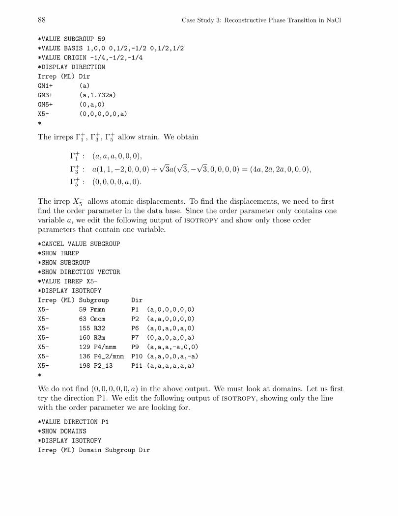
88 Case Study 3: Reconstructive Phase Transition in NaCl
*VALUE SUBGROUP 59
*VALUE BASIS 1,0,0 0,1/2,-1/2 0,1/2,1/2
*VALUE ORIGIN -1/4,-1/2,-1/4
*DISPLAY DIRECTION
Irrep (ML) Dir
GM1+ (a)
GM3+ (a,1.732a)
GM5+ (0,a,0)
X5- (0,0,0,0,0,a)
*
The irreps Γ+1 , Γ+
3 , Γ+5 allow strain. We obtain
Γ+1 : (a, a, a, 0, 0, 0),
Γ+3 : a(1, 1,−2, 0, 0, 0) +
√3a(√
3,−√
3, 0, 0, 0, 0) = (4a, 2a, 2a, 0, 0, 0),
Γ+5 : (0, 0, 0, 0, a, 0).
The irrep X−5 allows atomic displacements. To find the displacements, we need to firstfind the order parameter in the data base. Since the order parameter only contains onevariable a, we edit the following output of isotropy and show only those orderparameters that contain one variable.
*CANCEL VALUE SUBGROUP
*SHOW IRREP
*SHOW SUBGROUP
*SHOW DIRECTION VECTOR
*VALUE IRREP X5-
*DISPLAY ISOTROPY
Irrep (ML) Subgroup Dir
X5- 59 Pmmn P1 (a,0,0,0,0,0)
X5- 63 Cmcm P2 (a,a,0,0,0,0)
X5- 155 R32 P6 (a,0,a,0,a,0)
X5- 160 R3m P7 (0,a,0,a,0,a)
X5- 129 P4/nmm P9 (a,a,a,-a,0,0)
X5- 136 P4_2/mnm P10 (a,a,0,0,a,-a)
X5- 198 P2_13 P11 (a,a,a,a,a,a)
*
We do not find (0, 0, 0, 0, 0, a) in the above output. We must look at domains. Let us firsttry the direction P1. We edit the following output of isotropy, showing only the linewith the order parameter we are looking for.
*VALUE DIRECTION P1
*SHOW DOMAINS
*DISPLAY ISOTROPY
Irrep (ML) Domain Subgroup Dir
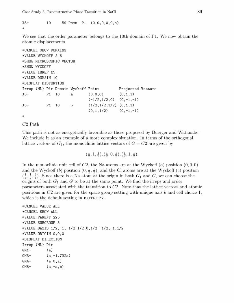
Case Study 3: Reconstructive Phase Transition in NaCl 89
X5- 10 59 Pmmn P1 (0,0,0,0,0,a)
*
We see that the order parameter belongs to the 10th domain of P1. We now obtain theatomic displacements.
*CANCEL SHOW DOMAINS
*VALUE WYCKOFF A B
*SHOW MICROSCOPIC VECTOR
*SHOW WYCKOFF
*VALUE IRREP X5-
*VALUE DOMAIN 10
*DISPLAY DISTORTION
Irrep (ML) Dir Domain Wyckoff Point Projected Vectors
X5- P1 10 a (0,0,0) (0,1,1)
(-1/2,1/2,0) (0,-1,-1)
X5- P1 10 b (1/2,1/2,1/2) (0,1,1)
(0,1,1/2) (0,-1,-1)
*
C2 Path
This path is not as energetically favorable as those proposed by Buerger and Watanabe.We include it as an example of a more complex situation. In terms of the orthogonallattice vectors of G1, the monoclinic lattice vectors of G = C2 are given by
( 12 , 1,
12 ), ( 1
2 , 0,12 ), ( 1
2 , 1,12 ).
In the monoclinic unit cell of C2, the Na atoms are at the Wyckoff (a) position (0, 0, 0)and the Wyckoff (b) position (0, 12 ,
12 ), and the Cl atoms are at the Wyckoff (c) position
( 14 ,
12 ,
34 ). Since there is a Na atom at the origin in both G1 and G, we can choose the
origins of both G1 and G to be at the same point. We find the irreps and orderparameters associated with the transition to C2. Note that the lattice vectors and atomicpositions in C2 are given for the space group setting with unique axis b and cell choice 1,which is the default setting in isotropy.
*CANCEL VALUE ALL
*CANCEL SHOW ALL
*VALUE PARENT 225
*VALUE SUBGROUP 5
*VALUE BASIS 1/2,-1,-1/2 1/2,0,1/2 -1/2,-1,1/2
*VALUE ORIGIN 0,0,0
*DISPLAY DIRECTION
Irrep (ML) Dir
GM1+ (a)
GM3+ (a,-1.732a)
GM4+ (a,0,a)
GM5+ (a,-a,b)
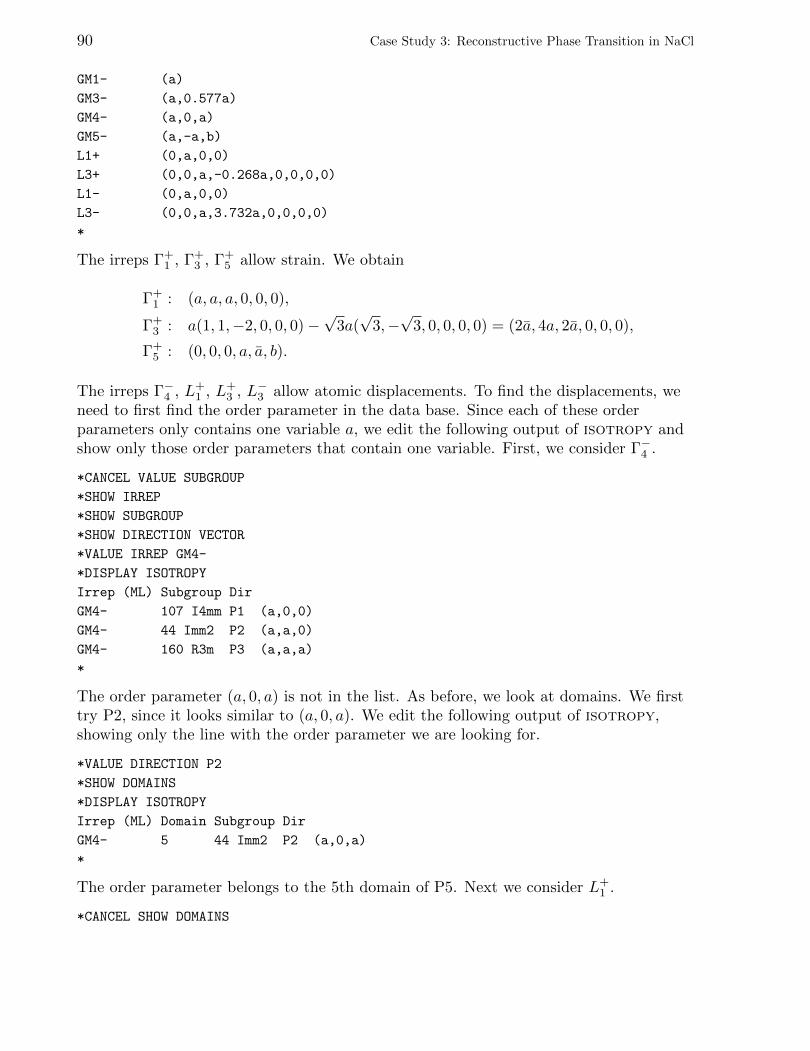
90 Case Study 3: Reconstructive Phase Transition in NaCl
GM1- (a)
GM3- (a,0.577a)
GM4- (a,0,a)
GM5- (a,-a,b)
L1+ (0,a,0,0)
L3+ (0,0,a,-0.268a,0,0,0,0)
L1- (0,a,0,0)
L3- (0,0,a,3.732a,0,0,0,0)
*
The irreps Γ+1 , Γ+
3 , Γ+5 allow strain. We obtain
Γ+1 : (a, a, a, 0, 0, 0),
Γ+3 : a(1, 1,−2, 0, 0, 0)−
√3a(√
3,−√
3, 0, 0, 0, 0) = (2a, 4a, 2a, 0, 0, 0),
Γ+5 : (0, 0, 0, a, a, b).
The irreps Γ−4 , L+1 , L+
3 , L−3 allow atomic displacements. To find the displacements, weneed to first find the order parameter in the data base. Since each of these orderparameters only contains one variable a, we edit the following output of isotropy andshow only those order parameters that contain one variable. First, we consider Γ−4 .
*CANCEL VALUE SUBGROUP
*SHOW IRREP
*SHOW SUBGROUP
*SHOW DIRECTION VECTOR
*VALUE IRREP GM4-
*DISPLAY ISOTROPY
Irrep (ML) Subgroup Dir
GM4- 107 I4mm P1 (a,0,0)
GM4- 44 Imm2 P2 (a,a,0)
GM4- 160 R3m P3 (a,a,a)
*
The order parameter (a, 0, a) is not in the list. As before, we look at domains. We firsttry P2, since it looks similar to (a, 0, a). We edit the following output of isotropy,showing only the line with the order parameter we are looking for.
*VALUE DIRECTION P2
*SHOW DOMAINS
*DISPLAY ISOTROPY
Irrep (ML) Domain Subgroup Dir
GM4- 5 44 Imm2 P2 (a,0,a)
*
The order parameter belongs to the 5th domain of P5. Next we consider L+1 .
*CANCEL SHOW DOMAINS
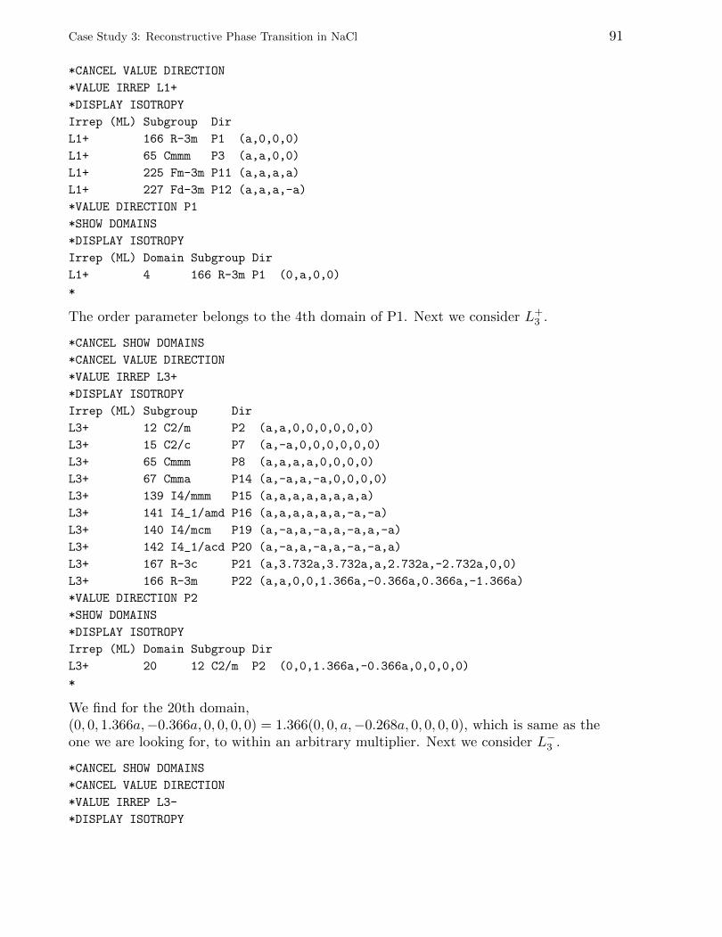
Case Study 3: Reconstructive Phase Transition in NaCl 91
*CANCEL VALUE DIRECTION
*VALUE IRREP L1+
*DISPLAY ISOTROPY
Irrep (ML) Subgroup Dir
L1+ 166 R-3m P1 (a,0,0,0)
L1+ 65 Cmmm P3 (a,a,0,0)
L1+ 225 Fm-3m P11 (a,a,a,a)
L1+ 227 Fd-3m P12 (a,a,a,-a)
*VALUE DIRECTION P1
*SHOW DOMAINS
*DISPLAY ISOTROPY
Irrep (ML) Domain Subgroup Dir
L1+ 4 166 R-3m P1 (0,a,0,0)
*
The order parameter belongs to the 4th domain of P1. Next we consider L+3 .
*CANCEL SHOW DOMAINS
*CANCEL VALUE DIRECTION
*VALUE IRREP L3+
*DISPLAY ISOTROPY
Irrep (ML) Subgroup Dir
L3+ 12 C2/m P2 (a,a,0,0,0,0,0,0)
L3+ 15 C2/c P7 (a,-a,0,0,0,0,0,0)
L3+ 65 Cmmm P8 (a,a,a,a,0,0,0,0)
L3+ 67 Cmma P14 (a,-a,a,-a,0,0,0,0)
L3+ 139 I4/mmm P15 (a,a,a,a,a,a,a,a)
L3+ 141 I4_1/amd P16 (a,a,a,a,a,a,-a,-a)
L3+ 140 I4/mcm P19 (a,-a,a,-a,a,-a,a,-a)
L3+ 142 I4_1/acd P20 (a,-a,a,-a,a,-a,-a,a)
L3+ 167 R-3c P21 (a,3.732a,3.732a,a,2.732a,-2.732a,0,0)
L3+ 166 R-3m P22 (a,a,0,0,1.366a,-0.366a,0.366a,-1.366a)
*VALUE DIRECTION P2
*SHOW DOMAINS
*DISPLAY ISOTROPY
Irrep (ML) Domain Subgroup Dir
L3+ 20 12 C2/m P2 (0,0,1.366a,-0.366a,0,0,0,0)
*
We find for the 20th domain,(0, 0, 1.366a,−0.366a, 0, 0, 0, 0) = 1.366(0, 0, a,−0.268a, 0, 0, 0, 0), which is same as theone we are looking for, to within an arbitrary multiplier. Next we consider L−3 .
*CANCEL SHOW DOMAINS
*CANCEL VALUE DIRECTION
*VALUE IRREP L3-
*DISPLAY ISOTROPY
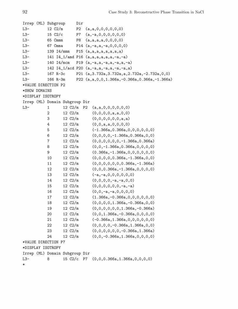
92 Case Study 3: Reconstructive Phase Transition in NaCl
Irrep (ML) Subgroup Dir
L3- 12 C2/m P2 (a,a,0,0,0,0,0,0)
L3- 15 C2/c P7 (a,-a,0,0,0,0,0,0)
L3- 65 Cmmm P8 (a,a,a,a,0,0,0,0)
L3- 67 Cmma P14 (a,-a,a,-a,0,0,0,0)
L3- 139 I4/mmm P15 (a,a,a,a,a,a,a,a)
L3- 141 I4_1/amd P16 (a,a,a,a,a,a,-a,-a)
L3- 140 I4/mcm P19 (a,-a,a,-a,a,-a,a,-a)
L3- 142 I4_1/acd P20 (a,-a,a,-a,a,-a,-a,a)
L3- 167 R-3c P21 (a,3.732a,3.732a,a,2.732a,-2.732a,0,0)
L3- 166 R-3m P22 (a,a,0,0,1.366a,-0.366a,0.366a,-1.366a)
*VALUE DIRECTION P2
*SHOW DOMAINS
*DISPLAY ISOTROPY
Irrep (ML) Domain Subgroup Dir
L3- 1 12 C2/m P2 (a,a,0,0,0,0,0,0)
2 12 C2/m (0,0,0,0,a,a,0,0)
3 12 C2/m (0,0,0,0,0,0,a,a)
4 12 C2/m (0,0,a,a,0,0,0,0)
5 12 C2/m (-1.366a,0.366a,0,0,0,0,0,0)
6 12 C2/m (0,0,0,0,-1.366a,0.366a,0,0)
7 12 C2/m (0,0,0,0,0,0,-1.366a,0.366a)
8 12 C2/m (0,0,-1.366a,0.366a,0,0,0,0)
9 12 C2/m (0.366a,-1.366a,0,0,0,0,0,0)
10 12 C2/m (0,0,0,0,0.366a,-1.366a,0,0)
11 12 C2/m (0,0,0,0,0,0,0.366a,-1.366a)
12 12 C2/m (0,0,0.366a,-1.366a,0,0,0,0)
13 12 C2/m (-a,-a,0,0,0,0,0,0)
14 12 C2/m (0,0,0,0,-a,-a,0,0)
15 12 C2/m (0,0,0,0,0,0,-a,-a)
16 12 C2/m (0,0,-a,-a,0,0,0,0)
17 12 C2/m (1.366a,-0.366a,0,0,0,0,0,0)
18 12 C2/m (0,0,0,0,1.366a,-0.366a,0,0)
19 12 C2/m (0,0,0,0,0,0,1.366a,-0.366a)
20 12 C2/m (0,0,1.366a,-0.366a,0,0,0,0)
21 12 C2/m (-0.366a,1.366a,0,0,0,0,0,0)
22 12 C2/m (0,0,0,0,-0.366a,1.366a,0,0)
23 12 C2/m (0,0,0,0,0,0,-0.366a,1.366a)
24 12 C2/m (0,0,-0.366a,1.366a,0,0,0,0)
*VALUE DIRECTION P7
*DISPLAY ISOTROPY
Irrep (ML) Domain Subgroup Dir
L3- 8 15 C2/c P7 (0,0,0.366a,1.366a,0,0,0,0)
*
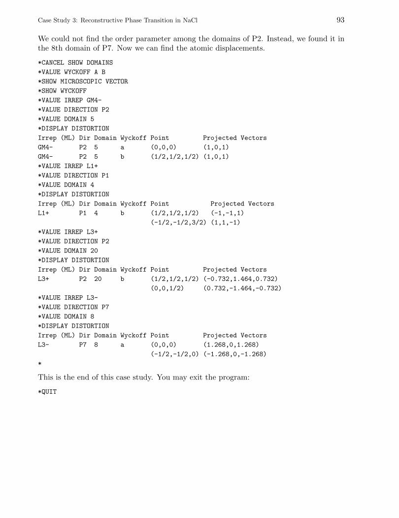
Case Study 3: Reconstructive Phase Transition in NaCl 93
We could not find the order parameter among the domains of P2. Instead, we found it inthe 8th domain of P7. Now we can find the atomic displacements.
*CANCEL SHOW DOMAINS
*VALUE WYCKOFF A B
*SHOW MICROSCOPIC VECTOR
*SHOW WYCKOFF
*VALUE IRREP GM4-
*VALUE DIRECTION P2
*VALUE DOMAIN 5
*DISPLAY DISTORTION
Irrep (ML) Dir Domain Wyckoff Point Projected Vectors
GM4- P2 5 a (0,0,0) (1,0,1)
GM4- P2 5 b (1/2,1/2,1/2) (1,0,1)
*VALUE IRREP L1+
*VALUE DIRECTION P1
*VALUE DOMAIN 4
*DISPLAY DISTORTION
Irrep (ML) Dir Domain Wyckoff Point Projected Vectors
L1+ P1 4 b (1/2,1/2,1/2) (-1,-1,1)
(-1/2,-1/2,3/2) (1,1,-1)
*VALUE IRREP L3+
*VALUE DIRECTION P2
*VALUE DOMAIN 20
*DISPLAY DISTORTION
Irrep (ML) Dir Domain Wyckoff Point Projected Vectors
L3+ P2 20 b (1/2,1/2,1/2) (-0.732,1.464,0.732)
(0,0,1/2) (0.732,-1.464,-0.732)
*VALUE IRREP L3-
*VALUE DIRECTION P7
*VALUE DOMAIN 8
*DISPLAY DISTORTION
Irrep (ML) Dir Domain Wyckoff Point Projected Vectors
L3- P7 8 a (0,0,0) (1.268,0,1.268)
(-1/2,-1/2,0) (-1.268,0,-1.268)
*
This is the end of this case study. You may exit the program:
*QUIT

94 Case Study 3: Reconstructive Phase Transition in NaCl
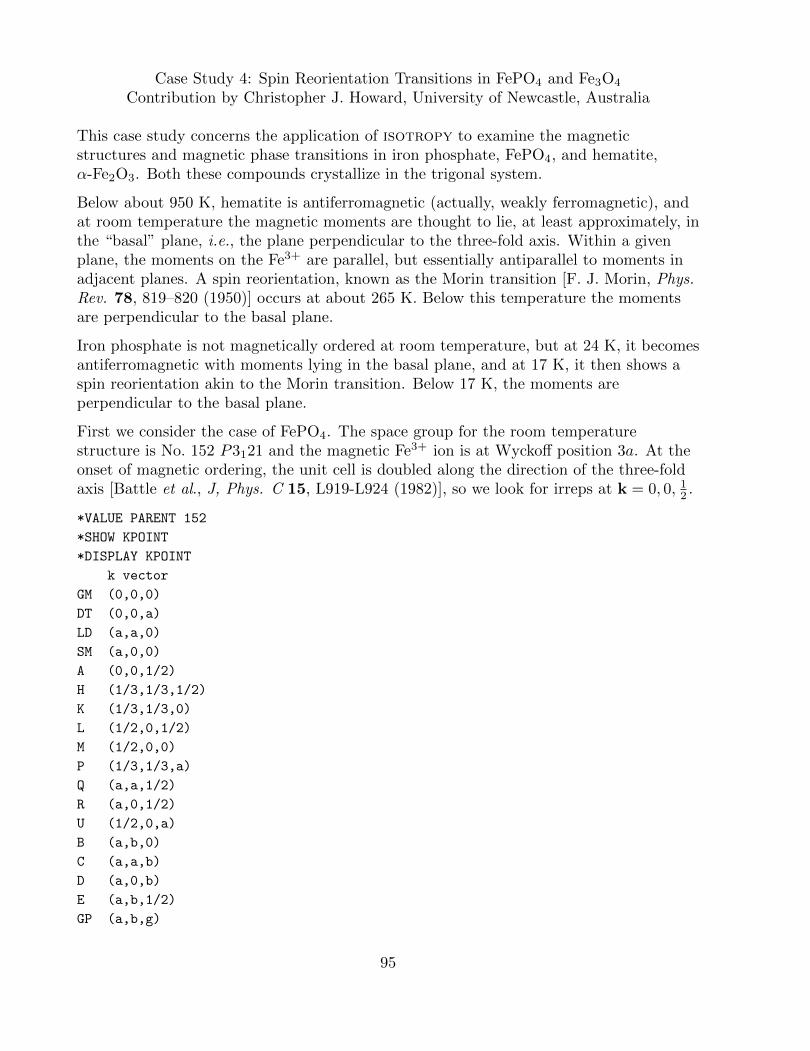
Case Study 4: Spin Reorientation Transitions in FePO4 and Fe3O4
Contribution by Christopher J. Howard, University of Newcastle, Australia
This case study concerns the application of isotropy to examine the magneticstructures and magnetic phase transitions in iron phosphate, FePO4, and hematite,α-Fe2O3. Both these compounds crystallize in the trigonal system.
Below about 950 K, hematite is antiferromagnetic (actually, weakly ferromagnetic), andat room temperature the magnetic moments are thought to lie, at least approximately, inthe “basal” plane, i.e., the plane perpendicular to the three-fold axis. Within a givenplane, the moments on the Fe3+ are parallel, but essentially antiparallel to moments inadjacent planes. A spin reorientation, known as the Morin transition [F. J. Morin, Phys.Rev. 78, 819–820 (1950)] occurs at about 265 K. Below this temperature the momentsare perpendicular to the basal plane.
Iron phosphate is not magnetically ordered at room temperature, but at 24 K, it becomesantiferromagnetic with moments lying in the basal plane, and at 17 K, it then shows aspin reorientation akin to the Morin transition. Below 17 K, the moments areperpendicular to the basal plane.
First we consider the case of FePO4. The space group for the room temperaturestructure is No. 152 P3121 and the magnetic Fe3+ ion is at Wyckoff position 3a. At theonset of magnetic ordering, the unit cell is doubled along the direction of the three-foldaxis [Battle et al., J, Phys. C 15, L919-L924 (1982)], so we look for irreps at k = 0, 0, 12 .
*VALUE PARENT 152
*SHOW KPOINT
*DISPLAY KPOINT
k vector
GM (0,0,0)
DT (0,0,a)
LD (a,a,0)
SM (a,0,0)
A (0,0,1/2)
H (1/3,1/3,1/2)
K (1/3,1/3,0)
L (1/2,0,1/2)
M (1/2,0,0)
P (1/3,1/3,a)
Q (a,a,1/2)
R (a,0,1/2)
U (1/2,0,a)
B (a,b,0)
C (a,a,b)
D (a,0,b)
E (a,b,1/2)
GP (a,b,g)
95
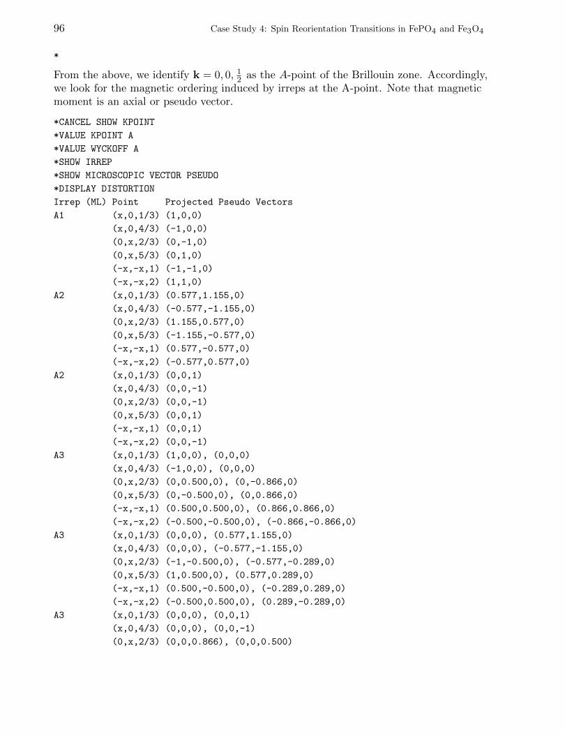
96 Case Study 4: Spin Reorientation Transitions in FePO4 and Fe3O4
*
From the above, we identify k = 0, 0, 12 as the A-point of the Brillouin zone. Accordingly,we look for the magnetic ordering induced by irreps at the A-point. Note that magneticmoment is an axial or pseudo vector.
*CANCEL SHOW KPOINT
*VALUE KPOINT A
*VALUE WYCKOFF A
*SHOW IRREP
*SHOW MICROSCOPIC VECTOR PSEUDO
*DISPLAY DISTORTION
Irrep (ML) Point Projected Pseudo Vectors
A1 (x,0,1/3) (1,0,0)
(x,0,4/3) (-1,0,0)
(0,x,2/3) (0,-1,0)
(0,x,5/3) (0,1,0)
(-x,-x,1) (-1,-1,0)
(-x,-x,2) (1,1,0)
A2 (x,0,1/3) (0.577,1.155,0)
(x,0,4/3) (-0.577,-1.155,0)
(0,x,2/3) (1.155,0.577,0)
(0,x,5/3) (-1.155,-0.577,0)
(-x,-x,1) (0.577,-0.577,0)
(-x,-x,2) (-0.577,0.577,0)
A2 (x,0,1/3) (0,0,1)
(x,0,4/3) (0,0,-1)
(0,x,2/3) (0,0,-1)
(0,x,5/3) (0,0,1)
(-x,-x,1) (0,0,1)
(-x,-x,2) (0,0,-1)
A3 (x,0,1/3) (1,0,0), (0,0,0)
(x,0,4/3) (-1,0,0), (0,0,0)
(0,x,2/3) (0,0.500,0), (0,-0.866,0)
(0,x,5/3) (0,-0.500,0), (0,0.866,0)
(-x,-x,1) (0.500,0.500,0), (0.866,0.866,0)
(-x,-x,2) (-0.500,-0.500,0), (-0.866,-0.866,0)
A3 (x,0,1/3) (0,0,0), (0.577,1.155,0)
(x,0,4/3) (0,0,0), (-0.577,-1.155,0)
(0,x,2/3) (-1,-0.500,0), (-0.577,-0.289,0)
(0,x,5/3) (1,0.500,0), (0.577,0.289,0)
(-x,-x,1) (0.500,-0.500,0), (-0.289,0.289,0)
(-x,-x,2) (-0.500,0.500,0), (0.289,-0.289,0)
A3 (x,0,1/3) (0,0,0), (0,0,1)
(x,0,4/3) (0,0,0), (0,0,-1)
(0,x,2/3) (0,0,0.866), (0,0,0.500)
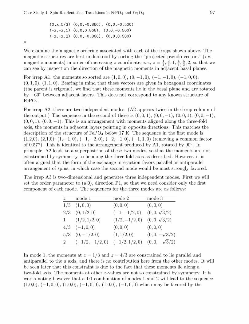
Case Study 4: Spin Reorientation Transitions in FePO4 and Fe3O4 97
(0,x,5/3) (0,0,-0.866), (0,0,-0.500)
(-x,-x,1) (0,0,0.866), (0,0,-0.500)
(-x,-x,2) (0,0,-0.866), (0,0,0.500)
*
We examine the magnetic ordering associated with each of the irreps shown above. Themagnetic structures are best understood by sorting the “projected pseudo vectors” (i.e.,magnetic moments) in order of increasing z coordinate, i.e., z = 1
3 ,23 , 1,
43 ,
53 , 2, so that we
can see by inspection the direction of the magnetic moments in adjacent basal planes.
For irrep A1, the moments so sorted are (1, 0, 0), (0,−1, 0), (−1,−1, 0), (−1, 0, 0),(0, 1, 0), (1, 1, 0). Bearing in mind that these vectors are given in hexagonal coordinates(the parent is trigonal), we find that these moments lie in the basal plane and are rotatedby −60◦ between adjacent layers. This does not correspond to any known structure ofFePO4.
For irrep A2, there are two independent modes. (A2 appears twice in the irrep column ofthe output.) The sequence in the second of these is (0, 0, 1), (0, 0,−1), (0, 0, 1), (0, 0,−1),(0, 0, 1), (0, 0,−1). This is an arrangement with moments aligned along the three-foldaxis, the moments in adjacent layers pointing in opposite directions. This matches thedescription of the structure of FePO4 below 17 K. The sequence in the first mode is(1,2,0), (2,1,0), (1,−1, 0), (−1,−2, 0), (−2,−1, 0), (−1, 1, 0) (removing a common factorof 0.577). This is identical to the arrangement produced by A1, rotated by 90◦. Inprinciple, A2 leads to a superposition of these two modes, so that the moments are notconstrained by symmetry to lie along the three-fold axis as described. However, it isoften argued that the form of the exchange interaction favors parallel or antiparallelarrangement of spins, in which case the second mode would be most strongly favored.
The irrep A3 is two-dimensional and generates three independent modes. First we willset the order parameter to (a,0), direction P1, so that we need consider only the firstcomponent of each mode. The sequences for the three modes are as follows:
z mode 1 mode 2 mode 3
1/3 (1, 0, 0) (0, 0, 0) (0, 0, 0)
2/3 (0, 1/2, 0) (−1,−1/2, 0) (0, 0,√
3/2)
1 (1/2, 1/2, 0) (1/2,−1/2, 0) (0, 0,√
3/2)
4/3 (−1, 0, 0) (0, 0, 0) (0, 0, 0)
5/3 (0,−1/2, 0) (1, 1/2, 0) (0, 0,−√
3/2)
2 (−1/2,−1/2, 0) (−1/2, 1/2, 0) (0, 0,−√
3/2)
In mode 1, the moments at z = 1/3 and z = 4/3 are constrained to lie parallel andantiparallel to the a axis, and there is no contribution here from the other modes. It willbe seen later that this constraint is due to the fact that these moments lie along atwo-fold axis. The moments at other z-values are not so constrained by symmetry. It isworth noting however that a 1:1 combination of modes 1 and 2 will lead to the sequence(1,0,0), (−1, 0, 0), (1,0,0), (−1, 0, 0), (1,0,0), (−1, 0, 0) which may be favored by the
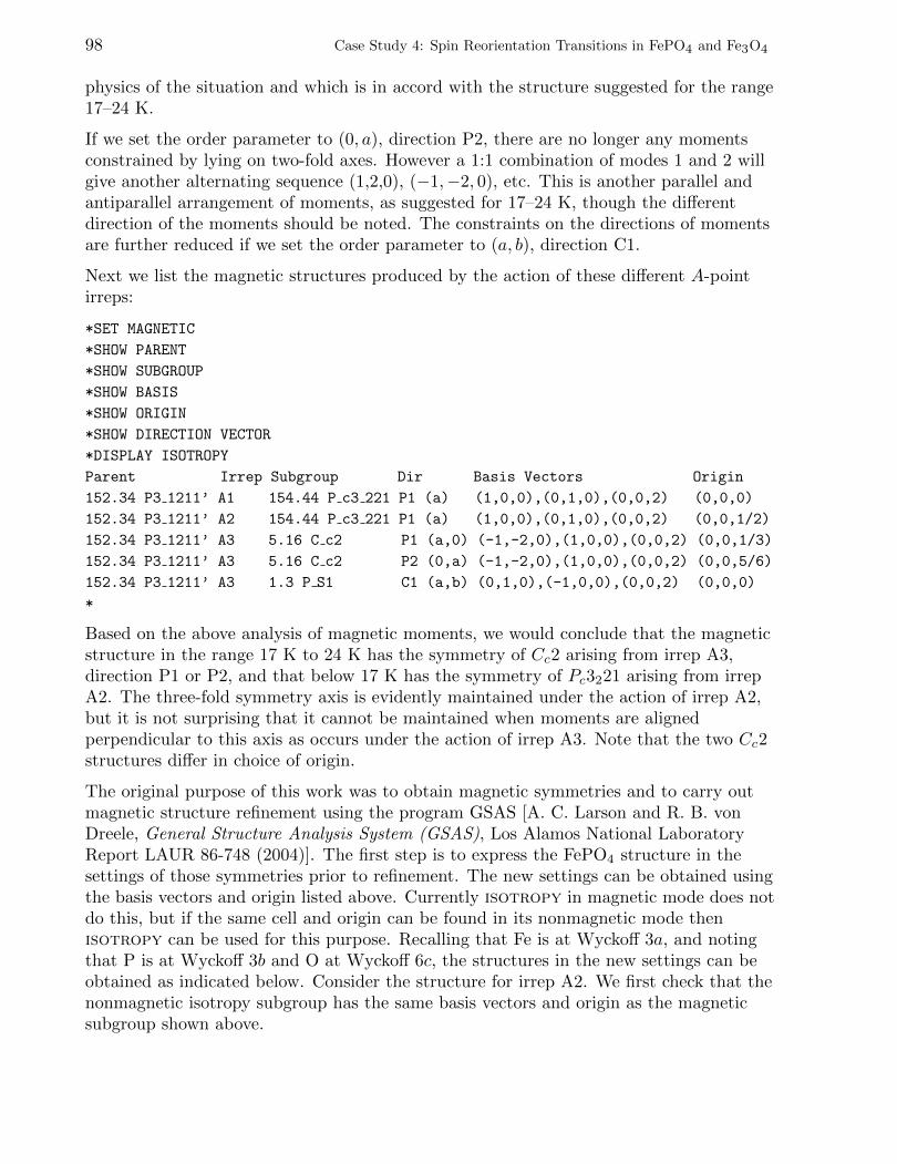
98 Case Study 4: Spin Reorientation Transitions in FePO4 and Fe3O4
physics of the situation and which is in accord with the structure suggested for the range17–24 K.
If we set the order parameter to (0, a), direction P2, there are no longer any momentsconstrained by lying on two-fold axes. However a 1:1 combination of modes 1 and 2 willgive another alternating sequence (1,2,0), (−1,−2, 0), etc. This is another parallel andantiparallel arrangement of moments, as suggested for 17–24 K, though the differentdirection of the moments should be noted. The constraints on the directions of momentsare further reduced if we set the order parameter to (a, b), direction C1.
Next we list the magnetic structures produced by the action of these different A-pointirreps:
*SET MAGNETIC
*SHOW PARENT
*SHOW SUBGROUP
*SHOW BASIS
*SHOW ORIGIN
*SHOW DIRECTION VECTOR
*DISPLAY ISOTROPY
Parent Irrep Subgroup Dir Basis Vectors Origin
152.34 P3 1211’ A1 154.44 P c3 221 P1 (a) (1,0,0),(0,1,0),(0,0,2) (0,0,0)
152.34 P3 1211’ A2 154.44 P c3 221 P1 (a) (1,0,0),(0,1,0),(0,0,2) (0,0,1/2)
152.34 P3 1211’ A3 5.16 C c2 P1 (a,0) (-1,-2,0),(1,0,0),(0,0,2) (0,0,1/3)
152.34 P3 1211’ A3 5.16 C c2 P2 (0,a) (-1,-2,0),(1,0,0),(0,0,2) (0,0,5/6)
152.34 P3 1211’ A3 1.3 P S1 C1 (a,b) (0,1,0),(-1,0,0),(0,0,2) (0,0,0)
*
Based on the above analysis of magnetic moments, we would conclude that the magneticstructure in the range 17 K to 24 K has the symmetry of Cc2 arising from irrep A3,direction P1 or P2, and that below 17 K has the symmetry of Pc3221 arising from irrepA2. The three-fold symmetry axis is evidently maintained under the action of irrep A2,but it is not surprising that it cannot be maintained when moments are alignedperpendicular to this axis as occurs under the action of irrep A3. Note that the two Cc2structures differ in choice of origin.
The original purpose of this work was to obtain magnetic symmetries and to carry outmagnetic structure refinement using the program GSAS [A. C. Larson and R. B. vonDreele, General Structure Analysis System (GSAS), Los Alamos National LaboratoryReport LAUR 86-748 (2004)]. The first step is to express the FePO4 structure in thesettings of those symmetries prior to refinement. The new settings can be obtained usingthe basis vectors and origin listed above. Currently isotropy in magnetic mode does notdo this, but if the same cell and origin can be found in its nonmagnetic mode thenisotropy can be used for this purpose. Recalling that Fe is at Wyckoff 3a, and notingthat P is at Wyckoff 3b and O at Wyckoff 6c, the structures in the new settings can beobtained as indicated below. Consider the structure for irrep A2. We first check that thenonmagnetic isotropy subgroup has the same basis vectors and origin as the magneticsubgroup shown above.
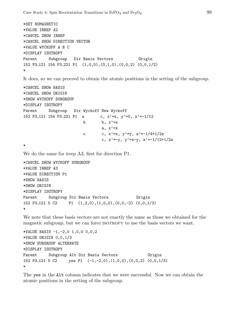
Case Study 4: Spin Reorientation Transitions in FePO4 and Fe3O4 99
*SET NOMAGNETIC
*VALUE IRREP A2
*CANCEL SHOW IRREP
*CANCEL SHOW DIRECTION VECTOR
*VALUE WYCKOFF A B C
*DISPLAY ISOTROPY
Parent Subgroup Dir Basis Vectors Origin
152 P3 121 154 P3 221 P1 (1,0,0),(0,1,0),(0,0,2) (0,0,1/2)
*
It does, so we can proceed to obtain the atomic positions in the setting of the subgroup.
*CANCEL SHOW BASIS
*CANCEL SHOW ORIGIN
*SHOW WYCKOFF SUBGROUP
*DISPLAY ISOTROPY
Parent Subgroup Dir Wyckoff New Wyckoff
152 P3 121 154 P3 221 P1 a c, x’=x, y’=0, z’=-1/12
b b, x’=x
a, x’=x
c c, x’=x, y’=y, z’=-1/4+1/2z
c, x’=-y, y’=x-y, z’=-1/12+1/2z
*
We do the same for irrep A3, first for direction P1.
*CANCEL SHOW WYCKOFF SUBGROUP
*VALUE IRREP A3
*VALUE DIRECTION P1
*SHOW BASIS
*SHOW ORIGIN
*DISPLAY ISOTROPY
Parent Subgroup Dir Basis Vectors Origin
152 P3 121 5 C2 P1 (1,2,0),(1,0,0),(0,0,-2) (0,0,1/3)
*
We note that these basis vectors are not exactly the same as those we obtained for themagnetic subgroup, but we can force isotropy to use the basis vectors we want.
*VALUE BASIS -1,-2,0 1,0,0 0,0,2
*VALUE ORIGIN 0,0,1/3
*SHOW SUBGROUP ALTERNATE
*DISPLAY ISOTROPY
Parent Subgroup Alt Dir Basis Vectors Origin
152 P3 121 5 C2 yes P1 (-1,-2,0),(1,0,0),(0,0,2) (0,0,1/3)
*
The yes in the Alt column indicates that we were successful. Now we can obtain theatomic positions in the setting of the subgroup.

100 Case Study 4: Spin Reorientation Transitions in FePO4 and Fe3O4
*CANCEL SHOW BASIS
*CANCEL SHOW ORIGIN
*SHOW WYCKOFF SUBGROUP
*DISPLAY ISOTROPY
Parent Subgroup Alt Dir Wyckoff New Wyckoff
152 P3 121 5 C2 yes P1 a a, y’=x
c, x’=-1/2x, y’=-1/2x, z’=1/6
‘ c, x’=1/2x, y’=-1/2x, z’=1/3
b, y’=x
b c, x’=0, y’=x, z’=1/4
c, x’=-1/2x, y’=-1/2x, z’=5/12
c, x’=-1/2x, y’=-1/2x, z’=11/12
c c, x’=-1/2y, y’=x-1/2y, z’=5/6+1/2z
c, x’=-1/2x+1/2y, y’=-1/2x-1/2y, z’=1/2z
c, x’=1/2x, y’=-1/2x+y, z’=1/6+1/2z
c, x’=-1/2y, y’=x-1/2y, z’=1/3+1/2z
c, x’=-1/2x+1/2y, y’=-1/2x-1/2y, z’=1/2+1/2z
c, x’=1/2x, y’=-1/2x+y, z’=2/3+1/2z
*
We repeat this also for direction P2.
*CANCEL SHOW WYCKOFF SUBGROUP
*VALUE DIRECTION P2
*VALUE ORIGIN 0,0,5/6
*SHOW BASIS
*SHOW ORIGIN
*DISPLAY ISOTROPY
Parent Subgroup Alt Dir Basis Vectors Origin
152 P3 121 5 C2 yes P2 (-1,-2,0),(1,0,0),(0,0,2) (0,0,5/6)
*CANCEL SHOW BASIS
*CANCEL SHOW ORIGIN
*SHOW WYCKOFF SUBGROUP
*DISPLAY ISOTROPY
Parent Subgroup Alt Dir Wyckoff New Wyckoff
152 P3 121 5 C2 yes P2 a c, x’=0, y’=x, z’=3/4
c, x’=-1/2x, y’=-1/2x, z’=11/12
c, x’=-1/2x, y’=-1/2x, z’=5/12
b a, y’=x
c, x’=-1/2x, y’=-1/2x, z’=1/6
c, x’=1/2x, y’=-1/2x, z’=1/3
b, y’=x
c c, x’=-1/2y, y’=x-1/2y, z’=7/12+1/2z
c, x’=-1/2x+1/2y, y’=-1/2x-1/2y, z’=3/4+1/2z
c, x’=1/2x, y’=-1/2x+y, z’=11/12+1/2z
c, x’=1/2y, y’=x-1/2y, z’=11/12-1/2z
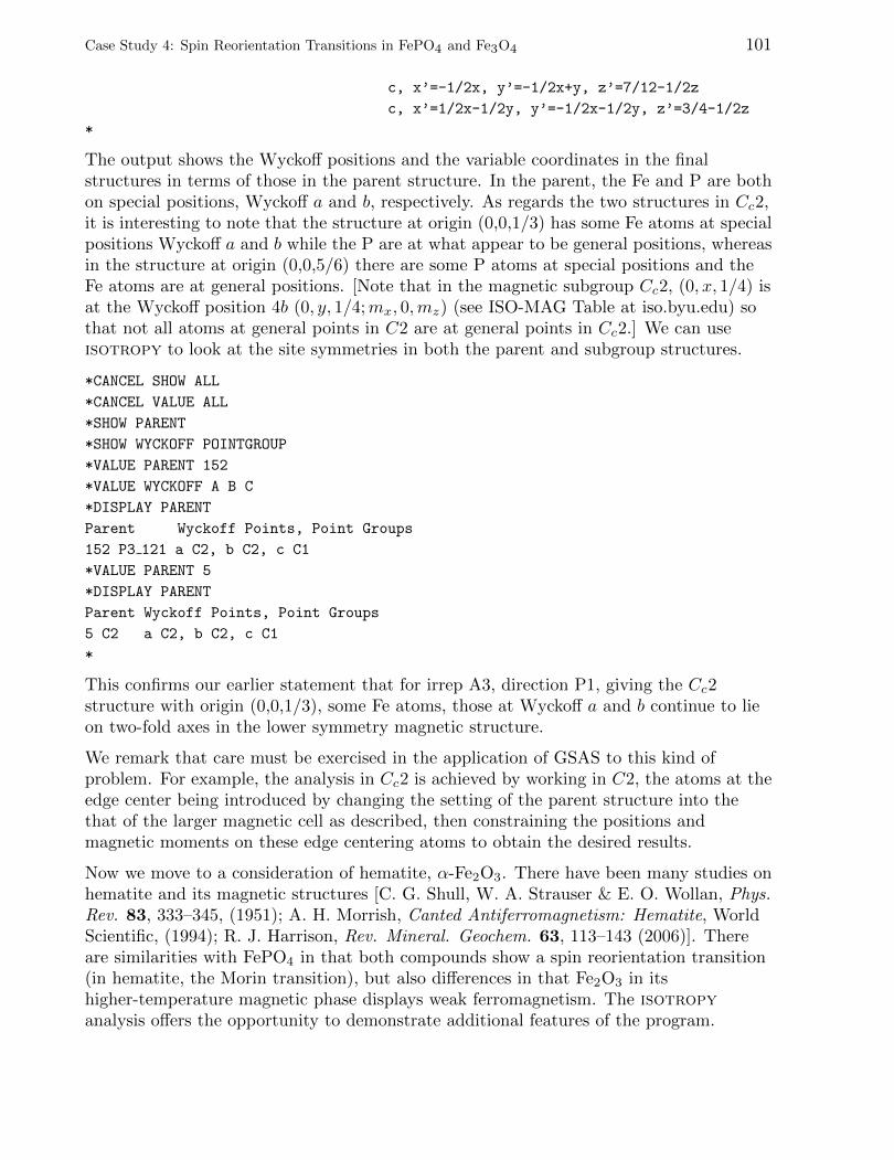
Case Study 4: Spin Reorientation Transitions in FePO4 and Fe3O4 101
c, x’=-1/2x, y’=-1/2x+y, z’=7/12-1/2z
c, x’=1/2x-1/2y, y’=-1/2x-1/2y, z’=3/4-1/2z
*
The output shows the Wyckoff positions and the variable coordinates in the finalstructures in terms of those in the parent structure. In the parent, the Fe and P are bothon special positions, Wyckoff a and b, respectively. As regards the two structures in Cc2,it is interesting to note that the structure at origin (0,0,1/3) has some Fe atoms at specialpositions Wyckoff a and b while the P are at what appear to be general positions, whereasin the structure at origin (0,0,5/6) there are some P atoms at special positions and theFe atoms are at general positions. [Note that in the magnetic subgroup Cc2, (0, x, 1/4) isat the Wyckoff position 4b (0, y, 1/4;mx, 0,mz) (see ISO-MAG Table at iso.byu.edu) sothat not all atoms at general points in C2 are at general points in Cc2.] We can useisotropy to look at the site symmetries in both the parent and subgroup structures.
*CANCEL SHOW ALL
*CANCEL VALUE ALL
*SHOW PARENT
*SHOW WYCKOFF POINTGROUP
*VALUE PARENT 152
*VALUE WYCKOFF A B C
*DISPLAY PARENT
Parent Wyckoff Points, Point Groups
152 P3 121 a C2, b C2, c C1
*VALUE PARENT 5
*DISPLAY PARENT
Parent Wyckoff Points, Point Groups
5 C2 a C2, b C2, c C1
*
This confirms our earlier statement that for irrep A3, direction P1, giving the Cc2structure with origin (0,0,1/3), some Fe atoms, those at Wyckoff a and b continue to lieon two-fold axes in the lower symmetry magnetic structure.
We remark that care must be exercised in the application of GSAS to this kind ofproblem. For example, the analysis in Cc2 is achieved by working in C2, the atoms at theedge center being introduced by changing the setting of the parent structure into thethat of the larger magnetic cell as described, then constraining the positions andmagnetic moments on these edge centering atoms to obtain the desired results.
Now we move to a consideration of hematite, α-Fe2O3. There have been many studies onhematite and its magnetic structures [C. G. Shull, W. A. Strauser & E. O. Wollan, Phys.Rev. 83, 333–345, (1951); A. H. Morrish, Canted Antiferromagnetism: Hematite, WorldScientific, (1994); R. J. Harrison, Rev. Mineral. Geochem. 63, 113–143 (2006)]. Thereare similarities with FePO4 in that both compounds show a spin reorientation transition(in hematite, the Morin transition), but also differences in that Fe2O3 in itshigher-temperature magnetic phase displays weak ferromagnetism. The isotropyanalysis offers the opportunity to demonstrate additional features of the program.
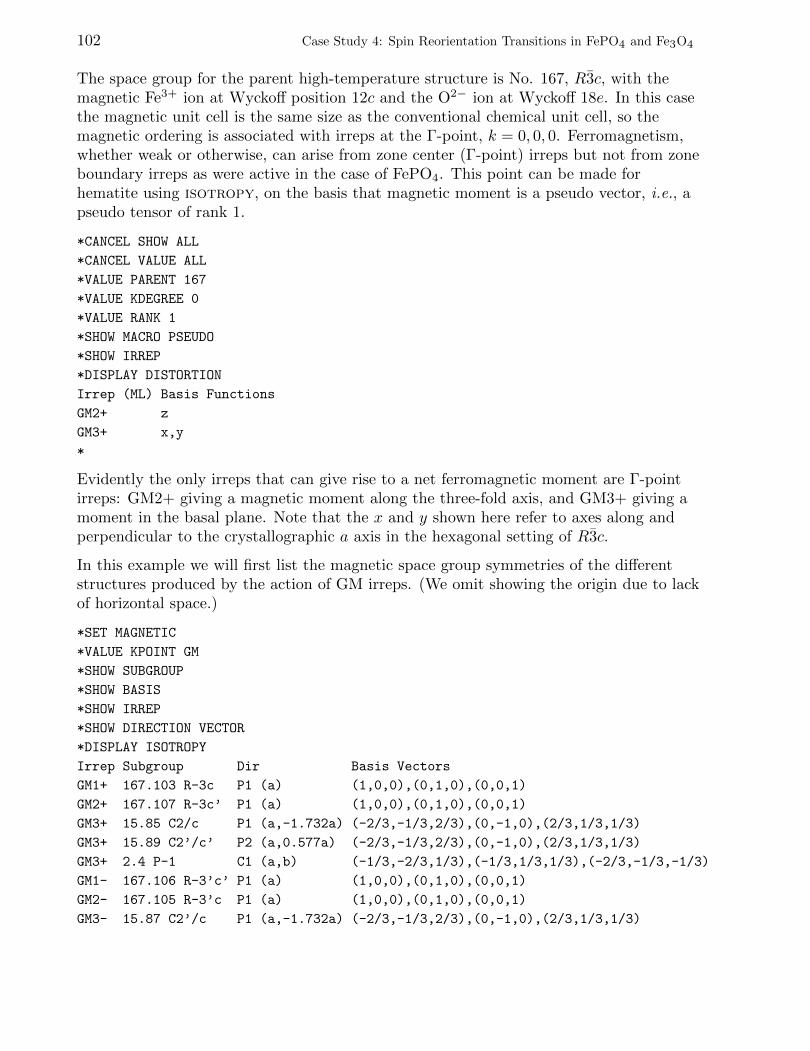
102 Case Study 4: Spin Reorientation Transitions in FePO4 and Fe3O4
The space group for the parent high-temperature structure is No. 167, R3c, with themagnetic Fe3+ ion at Wyckoff position 12c and the O2− ion at Wyckoff 18e. In this casethe magnetic unit cell is the same size as the conventional chemical unit cell, so themagnetic ordering is associated with irreps at the Γ-point, k = 0, 0, 0. Ferromagnetism,whether weak or otherwise, can arise from zone center (Γ-point) irreps but not from zoneboundary irreps as were active in the case of FePO4. This point can be made forhematite using isotropy, on the basis that magnetic moment is a pseudo vector, i.e., apseudo tensor of rank 1.
*CANCEL SHOW ALL
*CANCEL VALUE ALL
*VALUE PARENT 167
*VALUE KDEGREE 0
*VALUE RANK 1
*SHOW MACRO PSEUDO
*SHOW IRREP
*DISPLAY DISTORTION
Irrep (ML) Basis Functions
GM2+ z
GM3+ x,y
*
Evidently the only irreps that can give rise to a net ferromagnetic moment are Γ-pointirreps: GM2+ giving a magnetic moment along the three-fold axis, and GM3+ giving amoment in the basal plane. Note that the x and y shown here refer to axes along andperpendicular to the crystallographic a axis in the hexagonal setting of R3c.
In this example we will first list the magnetic space group symmetries of the differentstructures produced by the action of GM irreps. (We omit showing the origin due to lackof horizontal space.)
*SET MAGNETIC
*VALUE KPOINT GM
*SHOW SUBGROUP
*SHOW BASIS
*SHOW IRREP
*SHOW DIRECTION VECTOR
*DISPLAY ISOTROPY
Irrep Subgroup Dir Basis Vectors
GM1+ 167.103 R-3c P1 (a) (1,0,0),(0,1,0),(0,0,1)
GM2+ 167.107 R-3c’ P1 (a) (1,0,0),(0,1,0),(0,0,1)
GM3+ 15.85 C2/c P1 (a,-1.732a) (-2/3,-1/3,2/3),(0,-1,0),(2/3,1/3,1/3)
GM3+ 15.89 C2’/c’ P2 (a,0.577a) (-2/3,-1/3,2/3),(0,-1,0),(2/3,1/3,1/3)
GM3+ 2.4 P-1 C1 (a,b) (-1/3,-2/3,1/3),(-1/3,1/3,1/3),(-2/3,-1/3,-1/3)
GM1- 167.106 R-3’c’ P1 (a) (1,0,0),(0,1,0),(0,0,1)
GM2- 167.105 R-3’c P1 (a) (1,0,0),(0,1,0),(0,0,1)
GM3- 15.87 C2’/c P1 (a,-1.732a) (-2/3,-1/3,2/3),(0,-1,0),(2/3,1/3,1/3)
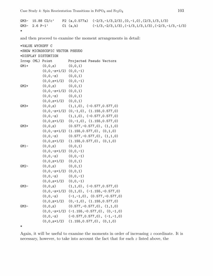
Case Study 4: Spin Reorientation Transitions in FePO4 and Fe3O4 103
GM3- 15.88 C2/c’ P2 (a,0.577a) (-2/3,-1/3,2/3),(0,-1,0),(2/3,1/3,1/3)
GM3- 2.6 P-1’ C1 (a,b) (-1/3,-2/3,1/3),(-1/3,1/3,1/3),(-2/3,-1/3,-1/3)
*
and then proceed to examine the moment arrangements in detail:
*VALUE WYCKOFF C
*SHOW MICROSCOPIC VECTOR PSEUDO
*DISPLAY DISTORTION
Irrep (ML) Point Projected Pseudo Vectors
GM1+ (0,0,z) (0,0,1)
(0,0,-z+1/2) (0,0,-1)
(0,0,-z) (0,0,1)
(0,0,z+1/2) (0,0,-1)
GM2+ (0,0,z) (0,0,1)
(0,0,-z+1/2) (0,0,1)
(0,0,-z) (0,0,1)
(0,0,z+1/2) (0,0,1)
GM3+ (0,0,z) (1,1,0), (-0.577,0.577,0)
(0,0,-z+1/2) (0,-1,0), (1.155,0.577,0)
(0,0,-z) (1,1,0), (-0.577,0.577,0)
(0,0,z+1/2) (0,-1,0), (1.155,0.577,0)
GM3+ (0,0,z) (0.577,-0.577,0), (1,1,0)
(0,0,-z+1/2) (1.155,0.577,0), (0,1,0)
(0,0,-z) (0.577,-0.577,0), (1,1,0)
(0,0,z+1/2) (1.155,0.577,0), (0,1,0)
GM1- (0,0,z) (0,0,1)
(0,0,-z+1/2) (0,0,-1)
(0,0,-z) (0,0,-1)
(0,0,z+1/2) (0,0,1)
GM2- (0,0,z) (0,0,1)
(0,0,-z+1/2) (0,0,1)
(0,0,-z) (0,0,-1)
(0,0,z+1/2) (0,0,-1)
GM3- (0,0,z) (1,1,0), (-0.577,0.577,0)
(0,0,-z+1/2) (0,1,0), (-1.155,-0.577,0)
(0,0,-z) (-1,-1,0), (0.577,-0.577,0)
(0,0,z+1/2) (0,-1,0), (1.155,0.577,0)
GM3- (0,0,z) (0.577,-0.577,0), (1,1,0)
(0,0,-z+1/2) (-1.155,-0.577,0), (0,-1,0)
(0,0,-z) (-0.577,0.577,0), (-1,-1,0)
(0,0,z+1/2) (1.155,0.577,0), (0,1,0)
*
Again, it will be useful to examine the moments in order of increasing z coordinate. It isnecessary, however, to take into account the fact that for each z listed above, the
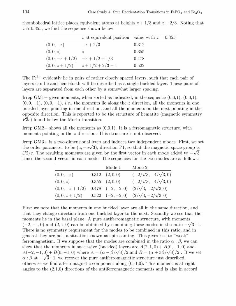
104 Case Study 4: Spin Reorientation Transitions in FePO4 and Fe3O4
rhombohedral lattice places equivalent atoms at heights z + 1/3 and z + 2/3. Noting thatz ≈ 0.355, we find the sequence shown below:
z at equivalent position value with z = 0.355
(0, 0,−z) −z + 2/3 0.312
(0, 0, z) z 0.355
(0, 0,−z + 1/2) −z + 1/2 + 1/3 0.478
(0, 0, z + 1/2) z + 1/2 + 2/3− 1 0.522
The Fe3+ evidently lie in pairs of rather closely spaced layers, such that each pair oflayers can be and henceforth will be described as a single buckled layer. These pairs oflayers are separated from each other by a somewhat larger spacing.
Irrep GM1+ gives moments, when sorted as indicated, in the sequence (0,0,1), (0,0,1),(0, 0,−1), (0, 0,−1), i.e., the moments lie along the z direction, all the moments in onebuckled layer pointing in one direction, and all the moments on the next pointing in theopposite direction. This is reported to be the structure of hematite (magnetic symmetryR3c) found below the Morin transition.
Irrep GM2+ shows all the moments as (0,0,1). It is a ferromagnetic structure, withmoments pointing in the z direction. This structure is not observed.
Irrep GM3+ is a two-dimensional irrep and induces two independent modes. First, we setthe order parameter to be (a,−a
√3), direction P1, so that the magnetic space group is
C2/c. The resulting moments are given by the first vector in each mode added to −√
3times the second vector in each mode. The sequences for the two modes are as follows:
Mode 1 Mode 2
(0, 0,−z) 0.312 (2, 0, 0) (−2/√
3,−4/√
3, 0)
(0, 0, z) 0.355 (2, 0, 0) (−2/√
3,−4/√
3, 0)
(0, 0,−z + 1/2) 0.478 (−2,−2, 0) (2/√
3,−2/√
3, 0)
(0, 0, z + 1/2) 0.522 (−2,−2, 0) (2/√
3,−2/√
3, 0)
First we note that the moments in one buckled layer are all in the same direction, andthat they change direction from one buckled layer to the next. Secondly we see that themoments lie in the basal plane. A pure antiferromagnetic structure, with moments(−2,−1, 0) and (2, 1, 0) can be obtained by combining these modes in the ratio −
√3 : 1.
There is no symmetry requirement for the modes to be combined in this ratio, and ingeneral they are not, a situation known as spin canting. This gives rise to “weak”ferromagnetism. If we suppose that the modes are combined in the ratio α : β, we canshow that the moments in successive (buckled) layers are A(2, 1, 0) +B(0,−1, 0) andA(−2,−1, 0) +B(0,−1, 0) where A = (α− β/
√3)/2 and B = (α+ 3β/
√3)/2 . If we set
α : β at −√
3 : 1, we recover the pure antiferromagnetic structure just described,otherwise we find a ferromagnetic component along (0,-1,0). This moment is at rightangles to the (2,1,0) directions of the antiferromagnetic moments and is also in accord
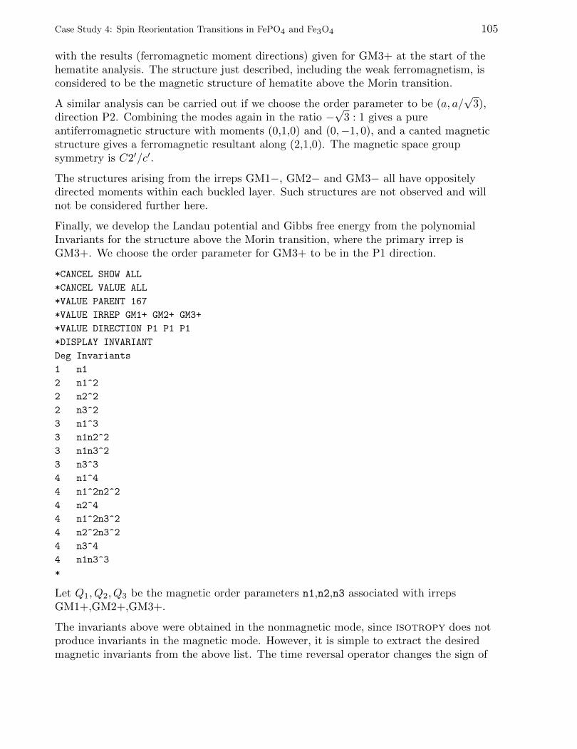
Case Study 4: Spin Reorientation Transitions in FePO4 and Fe3O4 105
with the results (ferromagnetic moment directions) given for GM3+ at the start of thehematite analysis. The structure just described, including the weak ferromagnetism, isconsidered to be the magnetic structure of hematite above the Morin transition.
A similar analysis can be carried out if we choose the order parameter to be (a, a/√
3),direction P2. Combining the modes again in the ratio −
√3 : 1 gives a pure
antiferromagnetic structure with moments (0,1,0) and (0,−1, 0), and a canted magneticstructure gives a ferromagnetic resultant along (2,1,0). The magnetic space groupsymmetry is C2′/c′.
The structures arising from the irreps GM1−, GM2− and GM3− all have oppositelydirected moments within each buckled layer. Such structures are not observed and willnot be considered further here.
Finally, we develop the Landau potential and Gibbs free energy from the polynomialInvariants for the structure above the Morin transition, where the primary irrep isGM3+. We choose the order parameter for GM3+ to be in the P1 direction.
*CANCEL SHOW ALL
*CANCEL VALUE ALL
*VALUE PARENT 167
*VALUE IRREP GM1+ GM2+ GM3+
*VALUE DIRECTION P1 P1 P1
*DISPLAY INVARIANT
Deg Invariants
1 n1
2 n1^2
2 n2^2
2 n3^2
3 n1^3
3 n1n2^2
3 n1n3^2
3 n3^3
4 n1^4
4 n1^2n2^2
4 n2^4
4 n1^2n3^2
4 n2^2n3^2
4 n3^4
4 n1n3^3
*
Let Q1, Q2, Q3 be the magnetic order parameters n1,n2,n3 associated with irrepsGM1+,GM2+,GM3+.
The invariants above were obtained in the nonmagnetic mode, since isotropy does notproduce invariants in the magnetic mode. However, it is simple to extract the desiredmagnetic invariants from the above list. The time reversal operator changes the sign of
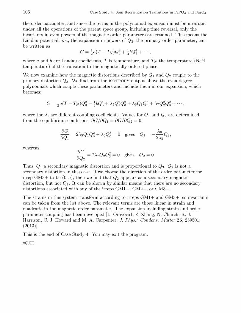
106 Case Study 4: Spin Reorientation Transitions in FePO4 and Fe3O4
the order parameter, and since the terms in the polynomial expansion must be invariantunder all the operations of the parent space group, including time reversal, only theinvariants in even powers of the magnetic order parameters are retained. This means theLandau potential, i.e., the expansion in powers of Q3, the primary order parameter, canbe written as
G = 12a(T − TN )Q2
3 + 14bQ
43 + · · · ,
where a and b are Landau coefficients, T is temperature, and TN the temperature (Neeltemperature) of the transition to the magnetically ordered phase.
We now examine how the magnetic distortions described by Q1 and Q2 couple to theprimary distortion Q3. We find from the isotropy output above the even-degreepolynomials which couple these parameters and include them in our expansion, whichbecomes:
G = 12a(T − TN )Q2
3 + 14bQ
43 + λ5Q
21Q
23 + λ6Q1Q
33 + λ7Q
22Q
23 + · · · ,
where the λi are different coupling coefficients. Values for Q1 and Q2 are determinedfrom the equilibrium conditions, ∂G/∂Q1 = ∂G/∂Q2 = 0:
∂G
∂Q1= 2λ5Q1Q
23 + λ6Q
33 = 0 gives Q1 = − λ6
2λ5Q3,
whereas∂G
∂Q2= 2λ7Q2Q
23 = 0 gives Q2 = 0.
Thus, Q1 a secondary magnetic distortion and is proportional to Q3. Q2 is not asecondary distortion in this case. If we choose the direction of the order parameter forirrep GM3+ to be (0, a), then we find that Q2 appears as a secondary magneticdistortion, but not Q1. It can be shown by similar means that there are no secondarydistortions associated with any of the irreps GM1−, GM2−, or GM3−.
The strains in this system transform according to irreps GM1+ and GM3+, so invariantscan be taken from the list above. The relevant terms are those linear in strain andquadratic in the magnetic order parameter. The expansion including strain and orderparameter coupling has been developed [L. Oravova1, Z. Zhang, N. Church, R. J.Harrison, C. J. Howard and M. A. Carpenter, J. Phys.: Condens. Matter 25, 259501,(2013)].
This is the end of Case Study 4. You may exit the program:
*QUIT


