ISOMET - David Kleinfeld Laboratory at UC San Diego Modulator-Driver... · double-sideband...
12
Series 230 May 1993 ISOMET INSTRUCTION MANUAL Acousto-OptIc Modulator/Drfver Series 230 (Analog Modulation) ***PRECAUTIONS*** Never operate the driver without proper cooling. The mounting face temperature must not exceed 70°C. Never operate the driver into an open circuited or short cirucited load. The video input level must not exceed 4V peak to peak (± 2V with respect to ground). ISOMET CORPORATION 5263 Port Royal Road Springfield, VA 22151 Telephone: 703-321-8301 Facsimile: 703-321-8546
Transcript of ISOMET - David Kleinfeld Laboratory at UC San Diego Modulator-Driver... · double-sideband...
Series 230 May 1993 ISOMET
INSTRUCTION MANUAL
Acousto-OptIc Modulator/Drfver Series 230
(Analog Modulation)
***PRECAUTIONS***
Never operate the driver without proper cooling. The mounting face temperature must not exceed 70°C.
Never operate the driver into an open circuited or short cirucited load.
The video input level must not exceed 4V peak to peak (± 2V with respect to ground).
ISOMET CORPORATION 5263 Port Royal Road Springfield, VA 22151
Telephone: 703-321-8301 Facsimile: 703-321-8546
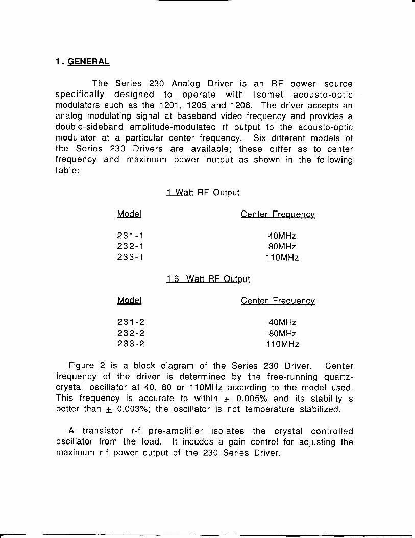
1 • GENERAL
The Series 230 Analog Driver is an RF power source specifically designed to operate with Isomet acousto-optic modulators such as the 1201, 1205 and 1206. The driver accepts an analog modulating signal at baseband video frequency and provides a double-sideband amplitude-modulated rf output to the acousto-optic modulator at a particular center frequency. Six different models of the Series 230 Drivers are available; these differ as to center frequency and maximum power output as shown in the following table:
1 Watt RF Output
MoM Center Frequency
2 3 1 - 1 40MHz 232- 1 80MHz 233- 1 110MHz
1.6 Watt RF Output
Model Center Frequency
2 3 1 - 2 40MHz 232- 2 80MHz 233- 2 110MHz
Figure 2 is a block diagram of the Series 230 Driver. Center frequency of the driver is determined by the free-running quartz-crystal oscillator at 40, 80 or 110MHz according to the model used. This frequency is accurate to within ± 0.005% and its stability is better than + 0.003%; the oscillator is not temperature stabilized.
A transistor r-f pre-amplifier isolates the crystal controlled oscillator from the load. It incudes a gain control for adjusting the maximum r-f power output of the 230 Series Driver.
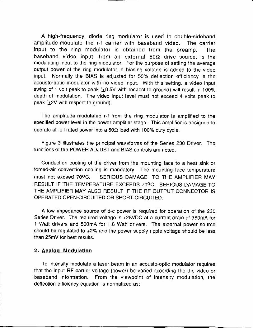
A high-frequency, diode ring modulator is used to double-sideband amplitude-modulate the r-f carrier with baseband video. The carrier input to the ring modulator is obtained from the preamp. The baseband video input, from an external 50Q drive source, is the modulating input to the ring modulator. For the purpose of setting the average output power of the ring modulator, a biasing voltage is added to the video input. Normally the BIAS is adjusted for 50% deflection efficiency in the acousto-optic modulator with no video input. With this setting, a video input swing of 1 volt peak to peak {±0.5V with respect to ground) will result in 100% depth of modulation. The video input level must not exceed 4 volts peak to peak {+2V with respect to ground).
The amplitude-modulated r-f from the ring modulator Is amplified to the specified power level in the power amplifier stage. This amplifier is designed to operate at full rated power into a 50Q load with 100% duty cycle.
Figure 3 illustrates the principal waveforms of the Series 230 Driver. The functions of the POWER ADJUST and BIAS controls are noted.
Conduction cooling of the driver from the mounting face to a heat sink or forced-air convection cooling is mandatory. The mounting face temperature must not exceed 70OC. SERIOUS DAMAGE TO THE AMPLIFIER MAY RESULT IF THE TEMPERATURE EXCEEDS 70OC. SERIOUS DAMAGE TO THE AMPLIFIER MAY ALSO RESULT IF THE RF OUTPUT CONNECTOR IS OPERATED OPEN-CIRCUITED OR SHORT-CIRCUITED.
A low impedance source of d-c power is required for operation of the 230 Series Driver. The required voltage is -I-28VDC at a current drain of 360mA for 1 Watt drivers and 500mA for 1.6 Watt drivers. The external power source should be regulated to ±2% and the power supply ripple voltage should be less than 25mV for best results.
2. Analog Modulation
To intensity modulate a laser beam in an acousto-optic modulator requires that the input RF carrier voltage (power) be varied according the the video or baseband information. From the viewpoint of intensity modulation, the deflection efficiency equation is normalized as:
il = Sin2 (kERF)
where i-j is the instantaneous intensity in the first order diffracted beam and E R F is the instantaneous RF envelop voltage across the matched transducer.
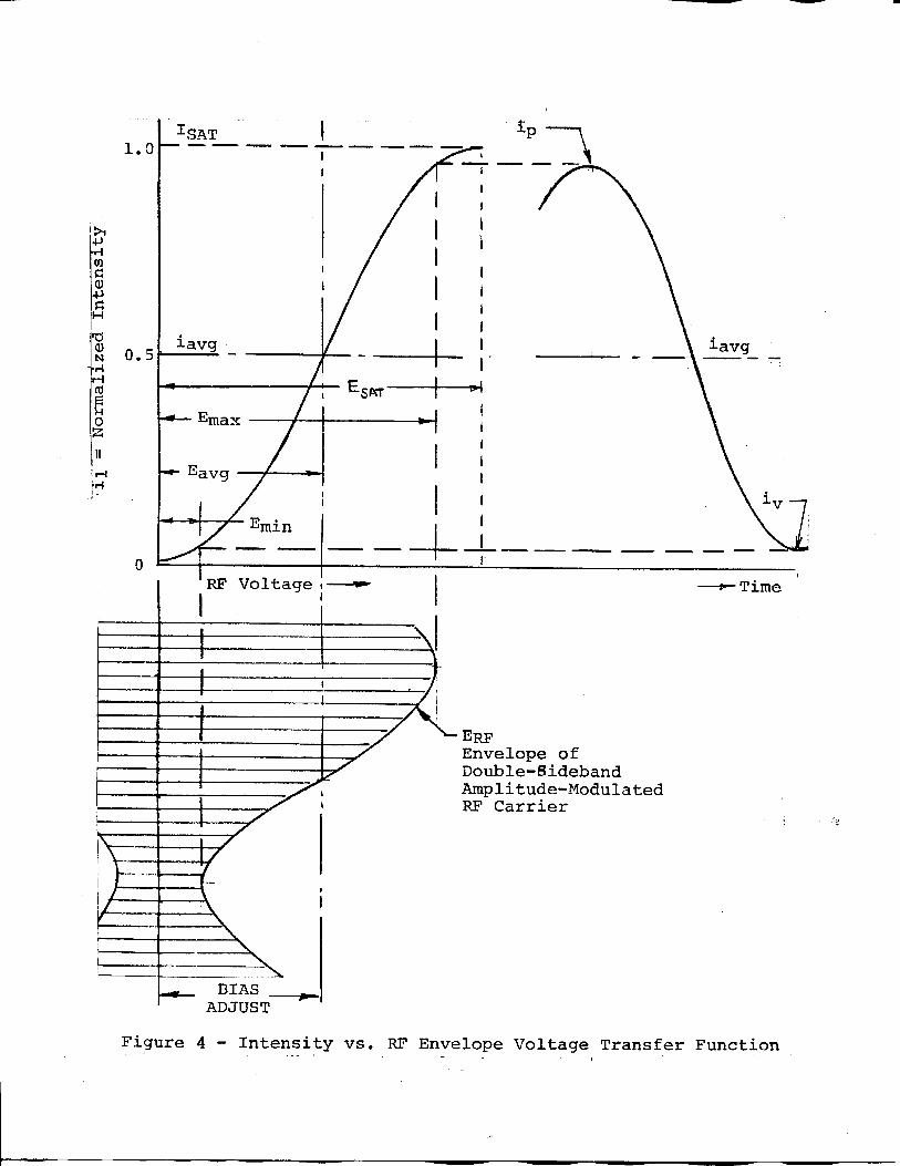
Figure 4 shows the intensity vs. RF envelop voltage transfer function of the acousto-optic modulator in normalized units with the typical waveforms superimposed, lit will be noted that the driving RF waveform is a double-sideband amplitude-modulated carrier. In effect, the acousto-optic interaction demodulates the RF carrier, transforming the modulation envelop (baseband signal) into intensity variation of the first order diffracted laser beam.
From the transfer function of figure 4, it can be seen that best linearity is obtained when the operating point of the modulator is set near the center of the i vs. E R F curve, that is iavg = ISAT/2 and eavg = ESAT/2. With this setting and with the depth of modulation limited to 80%, the total distortion in the intensity modulated beam will be less than 5%. Depth of modulation is defined as:
E - E . max mm
^max ""^mln
In the 230 Series Modulator Driver, two controls are included RF POWER ADJUST AND BIAS ADJUST. The RF POWER ADJUST control sets the peak Driver output at saturated power. The BIAS control sets the average drive power at Egvg- Depth of modulation is controlled by the amplitude of the video signal from the external video source.
3. Installation and Adjustment
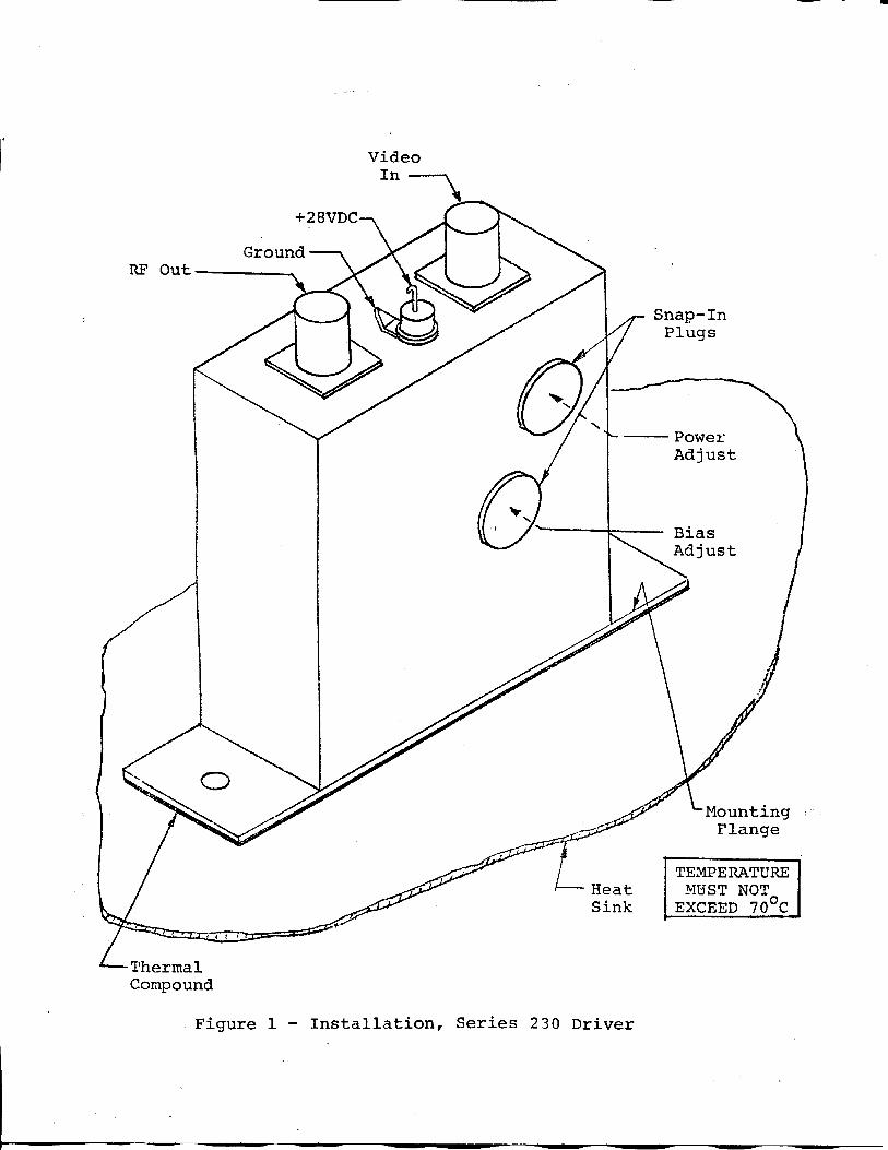
A. Install the Series 230 Driver on a heat sink as shown in figure 1. Use heat conducting compound between the Driver and mounting face and the heat sink.
B. With no d-c power applied, connect the +28VDC Ine to the center terminal of the feed-thru terminal as shown in figure 1. DO NOT APPLY POWER.
C. Connect the RF output BNC jack to an acousto-optic modulator (or a 50Q, RF load, if it is desired to measure the modulator RF output power).
D. Adjustment of the RF output power is best done with the Series 230 Driver connected to the acousto-optic modulator. The Driver maximum output power is factory preset to the specified level (1 Watt on.eWatts).
The optimum RF power level required for the modulator to produce maximum first order Intensity will be different at various laser wavelengths. Applying RF power in excess of this optimum level will cause a decrease in first order intensity (a false indication of insufficient RF power) and make accurate Bragg alignment difficult. It is therefore recommended that initial alignment be performed at a low RF power level.
1. Remove the BIAS ADJ and PWR ADJ snap-in plugs from the driver case (see figure 1).
2. With an insulated alignment tool or screwdriver:
a. Rotate the recessed bias adjust potentiometer fully CCW.
b. Rotate the PWR ADJ potentiometer fully CCW, then CW approximately 1/4 turn.
c. Apply +28VDC to the driver.
d. Observe the diffracted first-order output from the acousto-optic modulator and the undeflected zeroth order beam. Adjust the Bragg angle (rotate the modulator) to maximize first order beam intensity.
e. After Bragg angle has been optimized, slowly increase the RF power (rotate PWR ADJ CW) until maximum first order intensity is obtained. Record this intensity value (ISAT)-
f. Rotate the BIAS ADJ control clockwise to reduce the first order beam intensity to ISAT/2.
g. Replace the snap-in plug.
E. The driver is now ready for use as an analog modulator. Connect the external 50Q drive source to the VIDEO INPUT jacks. Adjust the video level for minimum distortion of the intensity modulated signal. A video input level of 1V PP (± 0.5V with respect to ground) will drive the modulator into saturation. The video input must not exceed 4V PP (±2V with respect to ground).
4. Operation
The Series 230 Modulator Driver is operated by applying +28VDC to the feedthrough terminal. There are no operating controls or adjustments.
I
video I n —
+28VDC
Ground RF Out
Snap-In Plugs
-Thermal Compound
Heat Sink
Power Adjust
B i a s A d j u s t
•Mounting Flange
TEMPERATURE MUST NOT
EXCEED 70°C
Figure 1 - I n s t a l l a t i o n , S e r i e s 2 30 D r i v e r
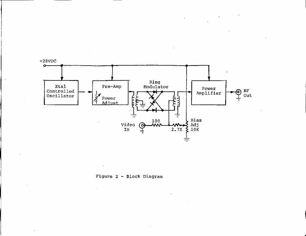
F i g u r e 2 - Block Diagram
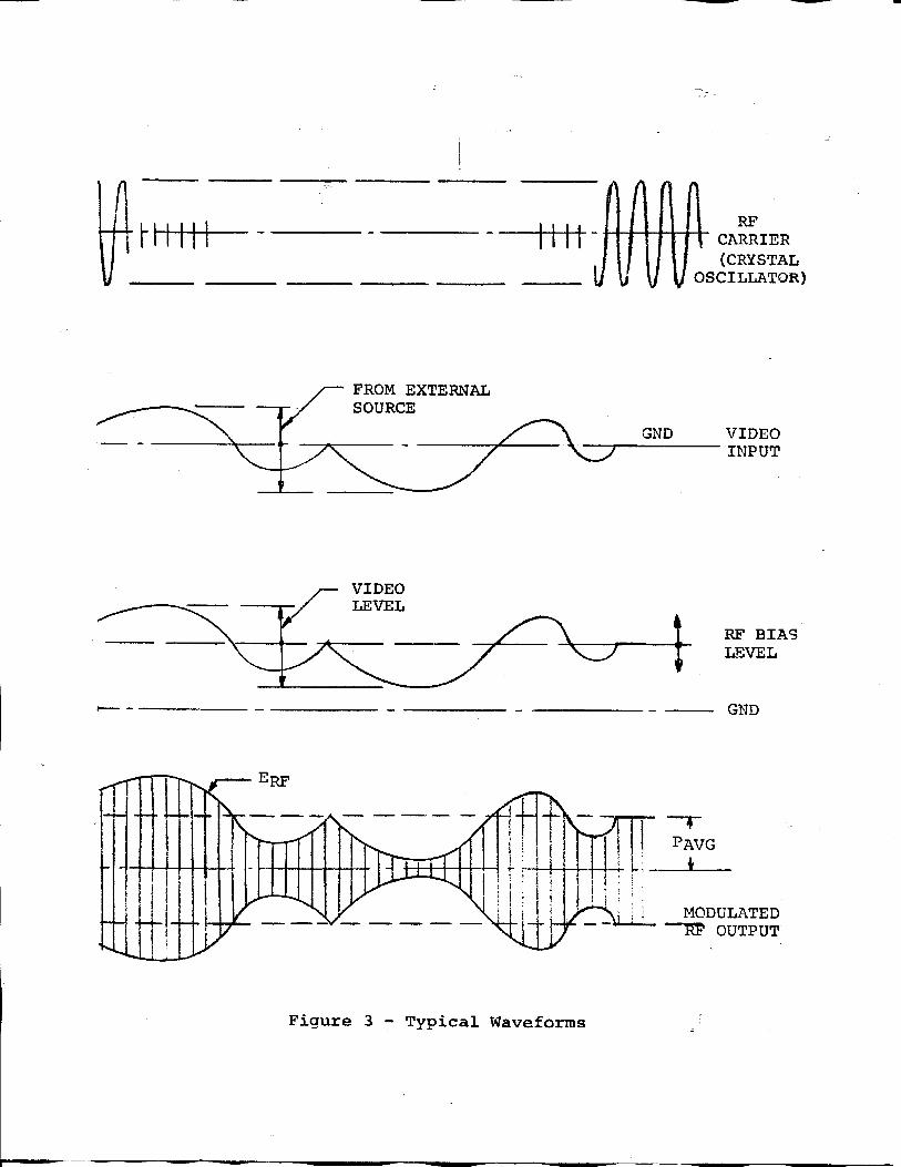
RF CARRIER (CRYSTAL
OSCILLATOR)
GND VIDEO INPUT
RF BIAS LEVEL
GND
ADJUST
Figure 4 - I n t e n s i t y v s . RF Envelope Voltage T r a n s f e r Function
230 SERIES ISOMET conpomiiok
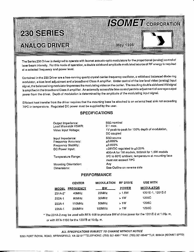
230 SERIES ANALOG DRIVER May 1998 1 The Series 230 Driver is designed to operate with Isomet acousto-optic modulators for the proportional (analog) control of laser beam intensity. For this mode of operatfon, a double sideband amplitude modulated source of RF energy is required at a selected frequency and power level.
Contained in the 230 Driver are a free-running quartz crystal carrier-frequency oscillator, a wideband balanced diode ring modulator, a bias level adjustment and a broadband Class A amplifier. Under control of the low level video (analog) input signal, the balanced ring modulatorimpresses the modulating video on the carrier. The resulting double sideband AM signal is amplified in the broadband Class A amplifier. An externally accessible bias control permits adjustment of average output power from the driver. Depth of modulation is determined by the amplitude of the modulating input signal.
Efficient heat transfer from the driver requires that the mounting base be attached to an external heat sink not exceeding 70^0 in temperature. Regulated DC power must be supplied by the user.
SPECIFICATIONS
Output Impedance: Load Mismatch VSWR: Video Input Voltage:
Input Impedance: Frequency Accuracy: Frequency Stability: DC Power Input:
Temperature Range:
Mounting Orientation: Dimensions:
son nominal 2:1 max. 1V peak-to-peak for 100% depth of modulation, DC coupled 50Q source ±0.005% ±0.003% +28VDC regulated to ±0.25% 400mA for 1W models, 500mA for 1.6W models O'-C to 60<C ambient, temperature at mounting face must not exceed 70°C Any See Outline on reverse side
PERFORMANCE CENTER MODULATION RF DRIVE USE WITH
MODEL FREQUENCY BW POWER MODULATOR
231A-2* 40MHz 20MHz > 1.6W 1201E-1, 1201E-2
232A-1 80MHz 35MHz > 1W 1205C
233A-1 110MHz 50MHz >1W 1206C
235A-1 200MHz 100MHz >1W 1250C
*The 231A-2may be used with RFA-108 to produce SWof drive power for the 1201E-2 at 1.06̂ 1 m.
or with RFA-1150 for the 1207B at 10.6^. m.
ALL SPECIFICATIONS SUBJECT TO CHANGE WITHOUT NOTICE
5263 PORT ROYAL ROAD. SPRINGFIELD. VA 2 2 1 5 r * T E L E P H O N E : (703) 321-8301 " F A X : (703) 321-8546**TLX: 899434 ( ISOMET SPFD)
230 SERIES ISOMET CORPORATION
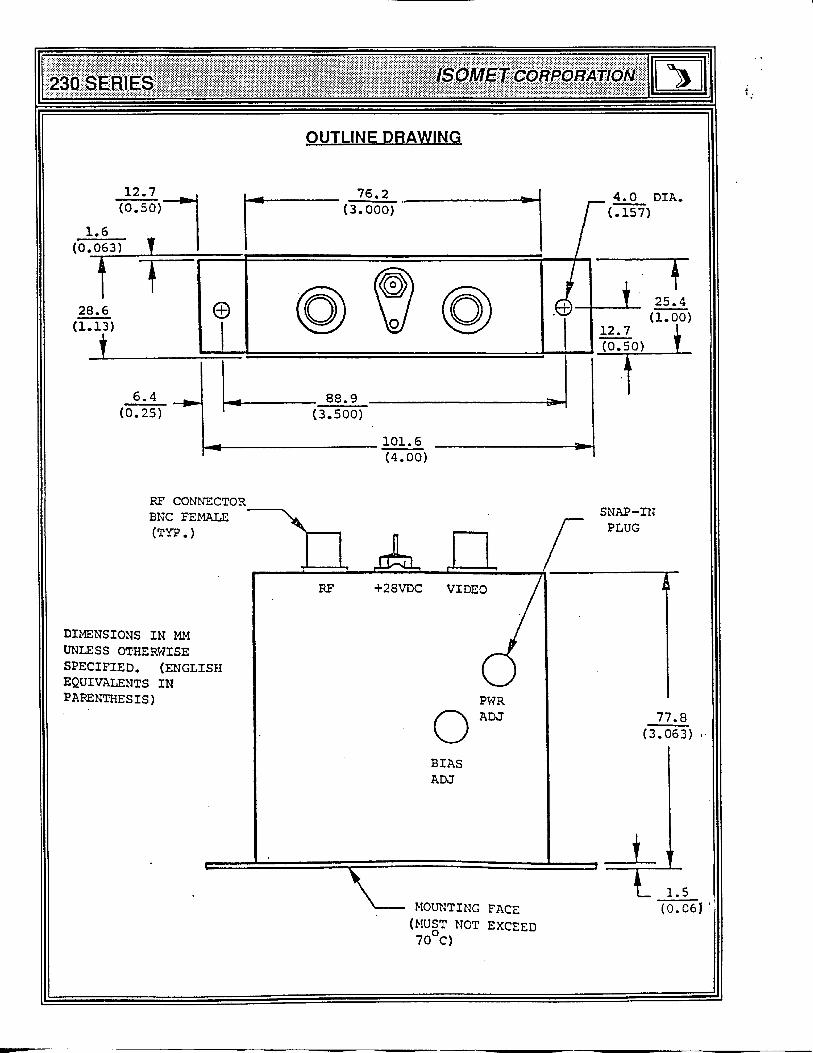
OUTLINE DRAWING
12.7 (0.50)'
1.6 (0.063) T I 28.6 (1.13)
e
76.2 (3.000)
4.0 DIA.
6.4 (0.25)
_ 88.9 (3.500)
101.6 (4.001
RF CONNECTOR BNC FEMALE (TYP.)
SNAP-IN PLUG
DIMENSIONS IN MM UNLESS OTHERWISE SPECIFIED. (ENGLISH EQUIVALENTS IN PARENTHESIS)
MOUNTING FACE (MUST NOT EXCEED 70 C)
( 0 . 0 6 )