ISOBUS Quick Reference Installation Guide · 2017-02-14 · to ECU Harness, 3 ft. CNHi Harness...
36
ISOBUS Quick Reference Installation Guide Liquid Fertilizer Anhydrous Ammonia Sprayer Spreader Slurry
Transcript of ISOBUS Quick Reference Installation Guide · 2017-02-14 · to ECU Harness, 3 ft. CNHi Harness...

1
ISOBUS Quick Reference Installation Guide
Liquid FertilizerAnhydrous Ammonia
SprayerSpreader
Slurry

2

3
1 ISOBUS System Overview ..............................................................3 1.1 Anhydrous Ammonia / Liquid Fertilizer ..............................................3 1.2 Sprayer ...........................................................................................3 1.3 Spreader ...........................................................................................4 1.4 Slurry ...........................................................................................42 Liquid Fertilizer / NH3 / Sprayer Installation .................................5 2.1 Cabling Diagram ...............................................................................5 2.2 Field-IQ/AccuGuide/IntelliRate Cabling .............................................6 2.3 Field-IQ/AccuGuide/IntelliRate Cabling Description ..........................7 2.4 Raven 4X0 Series Cabling ...............................................................8 2.5 Raven 4X0 Series Cabling Description .............................................9 2.6 Raven 4XX0 Series Cabling ...........................................................10 2.7 Raven 4XX0 Series Cabling Description ......................................... 11 2.8 Physical Installation ......................................................................... 11 2.9 Spartan Direct Injection System ......................................................153 Spreader Installation .....................................................................19 3.1 Cabling Diagram .............................................................................19 3.2 Field-IQ/AccuGuide/IntelliRate Cabling ...........................................20 3.3 Field-IQ/AccuGuide/IntelliRate Cabling Description ........................21 3.4 Raven 660 Series Cabling .............................................................22 3.5 Raven 660 Series Cabling Description ...........................................23 3.6 Physical Installation .........................................................................244 Slurry Installation ..........................................................................28 4.1 Slurry Cabling Diagram ...................................................................28 4.2 Slurry Cabling Diagram Description ................................................29 4.3 Physical Installation .........................................................................305 ISOBUS Resources .......................................................................33 5.1 ISOBUS Demo Stand ......................................................................33 5.2 ISOBUS Online Resources .............................................................33
Table of Contents

4

5
1 ISOBUS System Overview1.1 Anhydrous Ammonia/Liquid Fertilizer
12v
7
4
• ISOBUS ready tractor• ISOBUS compatible display
q ISOBUS Harness e ISOBUS Liquid ECU Harness
w ISOBUS ECU r Component cabling
1.2 Sprayer
12v
74
• ISOBUS ready tractor• ISOBUS compatible display
q ISOBUS Harness e ISOBUS Liquid ECU Harness
w ISOBUS ECU r Component cabling

6
1.3 Spreader
1 2
3 beltspeed
HYD
spinnerspeed
binlevel
binlevel
hoppercover
beltspeed
12v
7
• ISOBUS ready tractor• ISOBUS compatible display
q ISOBUS Harness e ISOBUS Liquid ECU Harness
w ISOBUS ECU
1.4 Slurry
12v
12
3
4• ISOBUS ready tractor• ISOBUS compatible display
q ISOBUS Harness e ISOBUS Liquid ECU Harness
w ISOBUS ECU r Component cabling

7
2 Liquid Fertilizer/NH3/Sprayer Installation2.1 Cabling Diagram

8
2.2 Field-IQ/AccuControl/IntelliRate Cabling

9
2.3 Field-IQ/AccuControl/IntelliRate Cabling DescriptionItem Description Part Number Part Number Description
1 ISOBUS Harness ME0502001-03 ME0502001-08 ME0502001-13 ME0502001-21 ME0502001-28 ME0502001-36 ME0502001-43
Implement with Master Switch - 3ft. Implement with Master Switch - 8ft. Implement with Master Switch - 13ft. Implement with Master Switch - 21ft. Implement with Master Switch - 28ft. Implement with Master Switch - 36ft. Implement with Master Switch - 43ft.
2 Liquid Fertilizer ECU ME30481010
3 Liquid Fertilizer ECU Complete Harness ME0512001
4 Master/Implement Switch
5 Radar input connection
6 Tank control connection
7 Power connection
8 Section connection
9 Rate connection
10 Aux. connection
11 Section Valve Adapter Cable ZTN80587 ZTN80961 ZTN77541 ZTN78225
Field-IQ 5 boom adapter Field-IQ 10 boom adapter Raven 7 boom adapter Raven 10 boom adapter
12 Field-IQ/AccuCtrl/IntelliRate Adapter Harness ME0502025
13 Aux. I/O
14 Spinner control (not applicable for liquid fertilizer)
15 Regulation connection ZTN80534 ZTN80586 ZTN80531 ZTN80960 ZTN81970 ZTN81554
Field-IQ to Raven Fast Valve Field-IQ to Raven control valve adapter Field-IQ to Dickey-john control valve Dickey-John PWM control valve adapter Raven Standard valve 063-0172-977 (round 4-pin lock ring connector) Raven Fast valve (flat 2-pin connector)
16 Flow connection
17 Flow Meter Cable
18 Flow Control Adapter Cable ZTN80584 ZTN80539
Field-IQ to Raven flowmeter adapter Field-IQ to Dickey-john encoder/flowmeter
19

10
2.4 Raven 4X0 Series Cabling

11
2.5 Raven 4X0 Series Cabling DescriptionItem Description Part Number Part Number Description
1 ISOBUS Harness ME0502001-03 ME0502001-08 ME0502001-13 ME0502001-21 ME0502001-28 ME0502001-36 ME0502001-43
Implement with Master Switch - 3ft. Implement with Master Switch - 8ft. Implement with Master Switch - 13ft. Implement with Master Switch - 21ft. Implement with Master Switch - 28ft. Implement with Master Switch - 36ft. Implement with Master Switch - 43ft.
2 Liquid ECU ME304810103 Liquid ECU to 4X0 Harness ME05120084 Master/Implement Switch5 Pressure connection6 Pressure Sensor * Denotes Raven part # 422-0000-090*7 Raven Flow Cable
* Denotes Raven part #115-0159-858* 115-0171-836*
Flow Cable 6 ft. 3 Boom Flow Cable 12 ft. 3 Boom
8 Control Valve9 Master On/Off Valve
10 Boom Valves11 Flox Extension Cable
* Denotes Raven part #
115-0159-016* 115-0159-017* 115-0159-019* 115-0171-544*
Flow Extension Cable 6 ft. Flow Extension Cable 12 ft. Flow Extension Cable 24 ft. Flow Extension Cable 36.5 ft.
12 Flow Meter

12
2.6 Raven 4XX0 Series Cabling

13
2.7 Raven 4XX0 Series Cabling DescriptionItem Description Part Number Part Number Description
1 ISOBUS Harness ME0502001-03 ME0502001-08 ME0502001-13 ME0502001-21 ME0502001-28 ME0502001-36 ME0502001-43
Implement with Master Switch - 3 ft. Implement with Master Switch - 8 ft. Implement with Master Switch - 13 ft. Implement with Master Switch - 21 ft. Implement with Master Switch - 28 ft. Implement with Master Switch - 36 ft. Implement with Master Switch - 43 ft.
2 Liquid ECU ME304810103 Liquid ECU to 4XX0 Harness ME05120094 Master/Implement Switch5 Raven Flow Cable
* Denotes Raven part #
115-0171-313* 115-0171-314* 115-0171-315* 115-0171-316*
Flow Cable 12 ft. 10 Boom Flow Cable 24 ft. 10 Boom Flow Cable 12 ft. 5 Boom Flow Cable 24 ft. 5 Boom
6 Control Valve7 Boom Valves
* Denotes Raven part #
063-0171-926* 063-0171-928* 063-0171-039*
Boom Valve Cable - 1 section Boom Valve Cable - 3 section Boom Valve Cable - 5 section
8 Pressure Sensor Cable
* Denotes Raven part #
115-0171-235* 115-0171-151* 115-0171-224* 115-0171-296*
Pressure Sensor Cable - 6 ft. Pressure Sensor Cable - 12 ft. Pressure Sensor Cable - 37 ft. Pressure Sensor Cable - 44 ft.
9 Optional Pressure Sensor * Denotes Raven part # 422-000-090*10 Flow Extension Cable
* Denotes Raven part #
115-0159-016* 115-0159-017* 115-0159-019* 115-0159-544*
Flow Extension Cable - 6 ft. Flow Extension Cable - 12 ft. Flow Extension Cable - 24 ft. Flow Extension Cable - 36.5 ft.
11 Flow Meter12 Flow Control Adapter Cable ZTN80584
ZTN80539 Field-IQ to Raven flowmeter adapter Field-IQ to DICKEY-john encoder/flowmeter

14
2.8 Physical Installation
1. Route the ISO Implement Cable from the ECU to the implement hitch point. This cable will mate with the Tractor ISOBUS connector. (factory equipped)
2. Locate a stable and flat area of the implement approximately 8 by 16 inches. Using four 1/4“ x 3/4“ length (or another length required) bolts and nylon locking nuts, bolt the ECU to the toolbar.

15
3. Plugin the ISO Implement Cable harness to the ISOBUS connection on the ECU. If the harness is connected incorrectly, the system will not power up.
4. Connect the Liquid ECU harness to the 42-pin connector on the ECU.

16
5. Connect the adapter harness (Field-IQ/AccuControl/IntelliRate, Raven 4X0, Raven 4XX0) to the Liquid ECU harness. Next, connect your adapter harness to the existing components on your implement.

17
2.9 Spartan Direct Injection SystemMueller Electronics recommends the Spartan Direct Injection System for NH3. The parts below are designed and tested to work with the Mueller NH3 system and should be ordered directly from SureFire Ag Systems.
Part Number: Description:508-04-110100 Spartan Injection Pump Kit Model 110 (2-10 oz/min) 508-04-120100 Spartan Injection Pump Kit Model 120 (3-20 oz/min) 508-04-130100 Spartan Injection Pump Kit Model 130 (5-40 oz/min) 508-04-140100 Spartan Injection Pump Kit Model 140 (10-80 oz/min)
All four pump models are identical as viewed from the outside. Each pump model has a different displacement to achieve the desired flow range. The flow switch on the 110 and 120 models is a special low flow switch (which also appears identical from the outside).
Specifications for all pump models: • Pressure: Max Operating 80 PSI - Care should be taken not to restrict pump outlet as it will develop up to 290 psi which may cause failure of plumbing fittings. • Voltage: 12 VDC vehicle electrical system • Current: Max 16.3 amps • Pump speed: 0 – 120 rpm • Pump Case Oil: Mobil Super 5W30 Conventional Motor Oil
Pump Kit Components: • Spartan Injection Pump - 3/8” QC Inlet - 3/8” QC Outlet or ¼” QC Outlet • 20’ Fused Power Cable w/ 480MP Connector– 6 AWG • Magnetic Mount Liquid Filled Pressure Gauge w/ Tee Connection • 10 PSI Pressure Maintaining Check Valve on Pump Outlet • 50 mesh strainer recommended for all installations - Strainer IS NOT included with pump kit - Strainer IS included on 20, 55 & 110 Gallon Spartan Tanks

18
Each Spartan pump includes a bag with the items shown to be installed according to this diagram.
Tank Kits:
Part Number: Description:508-02-100100 20 Gallon Spartan Tank Kit508-02-100200 55 Gallon Spartan Tank Kit508-02-100300 110 Gallon Spartan Tank Kit
All tank kits include: • Mounting location for Spartan pump on the tank bracket • 3/8” Hose for connection to pump • StrainerThe 55 and 100 Gallon Tank kits also include a black tank base for holding rinse water or antifreeze. This makes it extremely easy to flush the Spar-tan pump daily after use to reduce issues caused by chemical sitting in the pump.
Mixing chamber and one way check valve sold separately

19
Mixing Chambers:
Part Number: Description:716-333-0011-102 N-Serve Check ValvePart Number TBD NEW Mixing Chamber with built in injection port
The 55 and 100 Gallon Tank kits also include a black tank base for holding rinse water or antifreeze. This makes it extremely easy to flush the Spar-tan pump daily after use to reduce issues caused by chemical sitting in the pump.
Recommendations for N-Serve: • Spartan is a great pump for injecting N-Serve NH3 Stabilizer. • Given customer’s implement width, rates and speed SureFire will help choose the right pump model to fit their needs. • For many N-Serve cases, the Spartan 130 at 5-40 oz/min is the best fit.
Width Speed Rate Spartan Flow30 feet 4 MPH 1 qt / acre 7.8 oz/min40 feet 4 MPH 1 qt / acre 10.3 oz/min60 feet 10 MPH 1 qt / acre 38.8 oz/min
For any 30-60 ft wide applicator running 4-10 MPH speeds and applying the recommended rate of 1 quart N-Serve / acre, the Spartan 130 model is recommended.

20
Spartan Injection & Raven HP Cabling Guide:
Part Number: Description:ME0512010 Harness, Boost Pump AdapterME30322547 Harness, In-cab CPC Connector

21
3 Spreader Installation3.1 Cabling DiagramME SPREADER GOOD
SpreaderECU
Spreader ECUHarness
ISOBUS HarnessImplement withMaster Switch
1a
Field IQ/ AccuCtrl/IntelliRate
Adapter
Raven 66022 pin Adapter
Trimble ISOto ECU Harness, 3 ft.
CNHi Harness#77611-01#75528-xx
ratecontrol
encoder
spinnercontrol
spinnercontrol
Aux. I/O
WheelSpeed
OR
Foot Pedal Extension, 15ft.
Foot Pedalwith 12 ft. Cable
Master / implementswitch
1b
5
2
3
4a 4b
SPREADER SYSTEMItem Description1a ISOBUS Harness1b Trimble ISO to ECU Harness2 Spreader ECU3 Spreader Complete Harness4a Raven 660 22-pin Adapter4b FIQ/AccuCrtl/IntelliRate Adapter5 Foot Pedal w/ 12 ft. cable

22
3.2 Field-IQ/AccuControl/IntelliRate Cabling
ME SPREADER GOOD
1
2
3
7
8
4
5
6
9 10
11 1213
14 15

23
3.3 Field-IQ/AccuControl/IntelliRate Cabling DescriptionField-IQ / AccuControl / IntelliRate Spreader HarnessItem Description Part Number Part Number Description1 ISOBUS Harness ME0502001-03
ME0502001-08ME0502001-13ME0502001-21ME0502001-28ME0502001-36ME0502001-43
Implement with Master Switch - 3ft. Implement with Master Switch - 8ft. Implement with Master Switch - 13ft. Implement with Master Switch - 21ft. Implement with Master Switch - 28ft. Implement with Master Switch - 36ft. Implement with Master Switch - 43ft.
2 Spreader ECU ME304810503 Spreader Complete Harness ME05110004 Master/Implement Switch5 Radar Input Connection6 Rate Connection7 Rate Control Extension8 Field-IQ/AccuCtrl/IntelliRate Adapter
HarnessME0502025
9 Aux Connection10 Spinner Control Connection11 Control Connection12 Feedback Connection13 Spreader gate height & spinner
speed Adapter CableZTN80507
14 Flow Control Adapter Cable: • Field-IQ to Raven Fast Valve • Field-IQ to Raven Control Valve adapter • Dickey-john Control Valve adapter(2 pin)
ZTN80534ZTN80586
ZTN80960
15 Field-IQ to Dickey-John encoder/flowmeter
ZTN80539

24
3.4 Raven 660 Series Cabling
ME SPREADER GOOD
1
14
2
3
4
5
6
7
8
9
10
1112 13
14

25
3.5 Raven 660 Series Cabling DescriptionRaven 660 Spreader HarnessItem Description Part Number Part Number Description1 ISOBUS Harness ME0502001-03
ME0502001-08ME0502001-13ME0502001-21ME0502001-28ME0502001-36ME0502001-43
Implement with Master Switch - 3ft. Implement with Master Switch - 8ft. Implement with Master Switch - 13ft. Implement with Master Switch - 21ft. Implement with Master Switch - 28ft. Implement with Master Switch - 36ft. Implement with Master Switch - 43ft.
2 Spreader ECU ME304810503 Spreader Complete Harness ME05110004 Master/Implement Switch5 Radar Input Connection6 Rate Connection7 Rate Control Extension8 Raven 660 Adapter Harness ME05020149 Spinner Control Connection10 Raven Flow Cable *Denotes Raven part # 115-0159-787*11 Encoder12 Flow Extension Cable
*Denotes Raven part #
115-0159-016*115-0159-017*115-0159-019*115-0171-544*
Flow Extension Cable - 6ft.Flow Extension Cable - 12ft.Flow Extension Cable - 24ft.Flow Extension Cable - 36.5ft.
13 Clutches and Sensors14 Hydraulic Valve Control
26
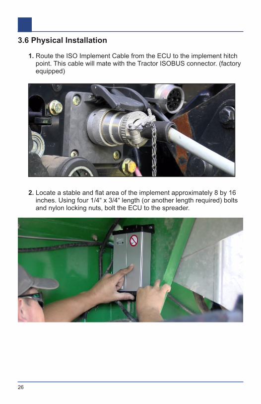
3.6 Physical Installation
1. Route the ISO Implement Cable from the ECU to the implement hitch point. This cable will mate with the Tractor ISOBUS connector. (factory equipped)
2. Locate a stable and flat area of the implement approximately 8 by 16 inches. Using four 1/4“ x 3/4“ length (or another length required) bolts and nylon locking nuts, bolt the ECU to the spreader.

27
3. Plugin the ISO Implement Cable harness to the ISOBUS connection on the ECU. If the harness is connected incorrectly, the system will not power up.
4. Connect the Liquid ECU harness to the 42-pin connector on the ECU.

28
5. Connect the Rate Extension harness to the Spreader ECU harness.
6. Plug the Rate Extension harness into your (Field-IQ/AccuControl/IntelliRate or Raven 660). Next, connect your adapter harness to the existing components on the spreader.

29

30
4 Slurry Installation4.1 Slurry Cabling Diagram

31
4.2 Slurry Cabling Diagram DescriptionISOBUS Slurry SystemItem Description Part Number Part Number Description1a ISOBUS Harness ME0502001-03
ME0502001-08ME0502001-13ME0502001-21ME0502001-28ME0502001-36ME0502001-43
Implement with Master Switch - 3ft. Implement with Master Switch - 8ft. Implement with Master Switch - 13ft. Implement with Master Switch - 21ft. Implement with Master Switch - 28ft. Implement with Master Switch - 36ft. Implement with Master Switch - 43ft.
1b Trimble ISO to ECU Harness ME05020362 Slurry ECU ME304811003 Slurry to Raven Adapter Harness ME05130004 Foot Pedal with 12 ft. Cable ME0520000
ME0520001ME3032259206
Foot Pedal with 12 ft. CableFoot Pedal Extension - 15 ft.Downloadbox
32
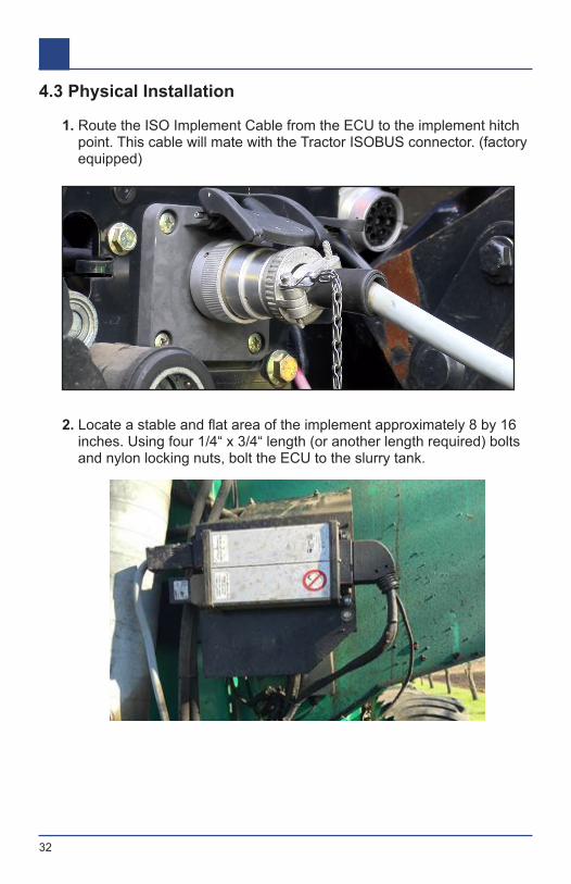
4.3 Physical Installation
1. Route the ISO Implement Cable from the ECU to the implement hitch point. This cable will mate with the Tractor ISOBUS connector. (factory equipped)
2. Locate a stable and flat area of the implement approximately 8 by 16 inches. Using four 1/4“ x 3/4“ length (or another length required) bolts and nylon locking nuts, bolt the ECU to the slurry tank.

33
3. Plugin the ISO Implement Cable harness to the ISOBUS connection on the ECU. Make sure you don’t connect the harness to the OUT side of the ECU. If the harness is connected incorrectly, the system will not power up.
4. Connect the Slurry Adapter harness to the 42-pin connector on the ECU.

34
5. Connect the adapter harness into the Raven 660 harness.

35
5 ISOBUS Resources5.1 ISOBUS Demo StandThis is a great tool for ISOBUS sales demo, ECU configuration, and software updating. Order the kit from the part numbers below.
Part Number: Description:ME0901001 ME_VB Demo BoardME0502015* Harness, Pro700 Case IH Display Adapter with CPC & Asst Steer-
ing BreakoutME0502001-03* Implement with Master Switch – 3 ft. Used to connect ECU to
Demo Stand*Not shown in picture above
Limited Stock - delivery times maybe 4 to 6 weeks
5.2 ISOBUS Online ResourcesCNH dealers are invited to have access to a private Google Drive with resources for ISOBUS control systems. The drive contains firmware, docu-mentation for setup and installation, ordering guides, service bulletins, and training videos. For access, send an email message to [email protected].
ME0901001

36