ISL3160E FN8980 RS-485/RS-422 Transceiver Mar 21, 2018
20
FN8980 Rev.0.00 Page 1 of 20 Mar 21, 2018 FN8980 Rev.0.00 Mar 21, 2018 ISL3160E ±10kV ESD Protected, +125°C, 40Mbps, 5V, Full-Duplex, Full Fail-Safe RS-485/RS-422 Transceiver DATASHEET The ISL3160E is a ±10kV IEC61000 ESD protected, 5V powered, full-duplex transceiver that meets both the RS-485 and RS-422 standards for balanced communication. It also features a large differential output voltage and high data rate (up to 40Mbps) and is offered in the standard industrial (-40°C to +85°C) and extended industrial (-40°C to +125°C) temperature ranges. The low bus currents (+220µA/-150µA) present a 1/5 unit load to the RS-485 bus. This allows up to 160 transceivers on the network without violating the RS-485 specification’s load limit and without using repeaters. This transceiver requires a 5V ±10% tolerance supply, and delivers at least a 2.1V differential output voltage over this supply range. This translates into better noise immunity (data integrity), longer reach, or the ability to drive up to six 120Ω terminations in “star” or other nonstandard bus topologies at the exceptional 40Mbps data rate. SCSI applications benefit from the ISL3160E’s low receiver and transmitter part-to-part skews. The ISL3160E is perfect for high speed parallel applications requiring simultaneous capture of large numbers of bits. The low bit-to-bit skew eases the timing constraints on the data latching signal. Receiver (Rx) inputs feature a “full fail-safe” design, which ensures a logic high Rx output if Rx inputs are floating, shorted, or terminated but undriven. Rx outputs feature high drive levels (typically >30mA at V OL = 1V) to ease the design of optically isolated interfaces. Hot plug circuitry ensures that the Tx and Rx outputs remain in a high impedance state while the power supply stabilizes. Driver (Tx) outputs are short-circuit protected, even for voltages exceeding the power supply voltage. Additionally, on-chip thermal shutdown circuitry disables the Tx outputs to prevent damage if power dissipation becomes excessive. Related Literature For a full list of related documents, visit our website • ISL3160E product page Features • High ESD protection on RS-485 I/O pins: ±10kV • Class 3 HBM ESD level on all other pins: >3kV • Large differential V OUT 2.8V into 54Ω better noise immunity, or drive up to 6 terminations • High data rates: up to 40Mbps • Specified for +125°C operation (FBZ), +85°C (IBZ) • 11/13ns (maximum) Tx/Rx propagation delays; 1.5ns (maximum) skew • 1/5 unit load allows up to 160 devices on the bus • Full fail-safe (open, shorted, terminated/undriven) receiver • High Rx I OL to drive opto-couplers for isolated applications • Hot plug - Tx and Rx outputs remain three-state during power-up • Low quiescent supply current: 4mA • Low current shutdown mode: 1µA • -7V to +12V common-mode input voltage range • Three-state Rx and Tx outputs • Operates from a single +5V supply (10% tolerance) • Current limiting and thermal shutdown for driver overload protection • Pb-free (RoHS compliant) Applications • Industrial robotics • SCSI “fast 40” drivers and receivers • Motor controller/position encoder systems • Factory automation • Field bus networks • Security networks • Building environmental control systems • Industrial/process control networks
Transcript of ISL3160E FN8980 RS-485/RS-422 Transceiver Mar 21, 2018

FN8980 Rev.0.00 Page 1 of 20Mar 21, 2018
FN8980Rev.0.00
Mar 21, 2018
ISL3160E±10kV ESD Protected, +125°C, 40Mbps, 5V, Full-Duplex, Full Fail-Safe RS-485/RS-422 Transceiver
DATASHEET
The ISL3160E is a ±10kV IEC61000 ESD protected, 5V powered, full-duplex transceiver that meets both the RS-485 and RS-422 standards for balanced communication. It also features a large differential output voltage and high data rate (up to 40Mbps) and is offered in the standard industrial (-40°C to +85°C) and extended industrial (-40°C to +125°C) temperature ranges. The low bus currents (+220µA/-150µA) present a 1/5 unit load to the RS-485 bus. This allows up to 160 transceivers on the network without violating the RS-485 specification’s load limit and without using repeaters.
This transceiver requires a 5V ±10% tolerance supply, and delivers at least a 2.1V differential output voltage over this supply range. This translates into better noise immunity (data integrity), longer reach, or the ability to drive up to six 120Ω terminations in “star” or other nonstandard bus topologies at the exceptional 40Mbps data rate.
SCSI applications benefit from the ISL3160E’s low receiver and transmitter part-to-part skews. The ISL3160E is perfect for high speed parallel applications requiring simultaneous capture of large numbers of bits. The low bit-to-bit skew eases the timing constraints on the data latching signal.
Receiver (Rx) inputs feature a “full fail-safe” design, which ensures a logic high Rx output if Rx inputs are floating, shorted, or terminated but undriven. Rx outputs feature high drive levels (typically >30mA at VOL = 1V) to ease the design of optically isolated interfaces.
Hot plug circuitry ensures that the Tx and Rx outputs remain in a high impedance state while the power supply stabilizes.
Driver (Tx) outputs are short-circuit protected, even for voltages exceeding the power supply voltage. Additionally, on-chip thermal shutdown circuitry disables the Tx outputs to prevent damage if power dissipation becomes excessive.
Related LiteratureFor a full list of related documents, visit our website
• ISL3160E product page
Features• High ESD protection on RS-485 I/O pins: ±10kV
• Class 3 HBM ESD level on all other pins: >3kV
• Large differential VOUT 2.8V into 54Ω better noise immunity, or drive up to 6 terminations
• High data rates: up to 40Mbps
• Specified for +125°C operation (FBZ), +85°C (IBZ)
• 11/13ns (maximum) Tx/Rx propagation delays; 1.5ns (maximum) skew
• 1/5 unit load allows up to 160 devices on the bus
• Full fail-safe (open, shorted, terminated/undriven) receiver
• High Rx IOL to drive opto-couplers for isolated applications
• Hot plug - Tx and Rx outputs remain three-state during power-up
• Low quiescent supply current: 4mA
• Low current shutdown mode: 1µA
• -7V to +12V common-mode input voltage range
• Three-state Rx and Tx outputs
• Operates from a single +5V supply (10% tolerance)
• Current limiting and thermal shutdown for driver overload protection
• Pb-free (RoHS compliant)
Applications• Industrial robotics
• SCSI “fast 40” drivers and receivers
• Motor controller/position encoder systems
• Factory automation
• Field bus networks
• Security networks
• Building environmental control systems
• Industrial/process control networks

FN8980 Rev.0.00 Page 2 of 20Mar 21, 2018
ISL3160E
Figure 1. Typical Operating Circuit
0.1µF+
D
R
12
11
10
9
14
2
3
4
5
6, 7
VCC
GND
RO
RE
DE
DI
A
B
Y
Z
+5V
0.1µF+
D
R12
11
10
9
14
2
3
4
5
6, 7
VCC
GND
RO
RE
DE
DI
A
B
Y
Z
+5V
RT
RT

FN8980 Rev.0.00 Page 3 of 20Mar 21, 2018
ISL3160E 1. Overview
1. Overview
1.1 Ordering Information
1.2 Pin Configurations
Part Number(Notes 2, 3) Part Marking
Temp. Range(°C)
Tape and Reel(Units)
Package(RoHS Compliant) Pkg. Dwg. #
ISL3160EIBZ ISL3160 EIBZ -40 to +85 - 14 Ld SOIC M14.15
ISL3160EIBZ-T (Note 1) ISL3160 EIBZ -40 to +85 2.5k 14 Ld SOIC M14.15
ISL3160EFBZ ISL3160 EFBZ -40 to +125 - 14 Ld SOIC M14.15
ISL3160EFBZ-T (Note 1) ISL3160 EFBZ -40 to +125 2.5k 14 Ld SOIC M14.15
Notes:1. Refer to TB347 for details about reel specifications.2. Pb-free plus anneal products employ special Pb-free material sets; molding compounds/die attach materials and 100% matte tin
plate termination finish, which are RoHS compliant and compatible with both SnPb and Pb-free soldering operations. Pb-free products are MSL classified at Pb-free peak reflow temperatures that meet or exceed the Pb-free requirements of IPC/JEDEC J STD-020.
3. For Moisture Sensitivity Level (MSL), refer to the ISL3160E product information page. For more information about MSL, refer to TB363.
Table 1. Key Differences Between High-Speed Interface Family of Parts
Part Number Full/Half Duplex VCC (V) VOD (V) Data Rate (Mbps)
ISL3160E Full 5 2.1 40
ISL3159E Half 5 2.1 40
ISL3259E Half 5 2.1 100
ISL3179E Half 3.3 1.5 40
ISL3180E Full 3.3 1.5 40
ISL3160E(14 Ld SOIC)
Top View
NC
RO
RE
DE
DI
GND
GND
VCC
NC
A
B
Z
Y
NC
1
2
3
4
5
6
7
14
13
12
11
10
9
8

FN8980 Rev.0.00 Page 4 of 20Mar 21, 2018
ISL3160E 1. Overview
1.3 Pin Descriptions
1.4 Truth Tables
Pin Number Pin Function
2 RO Receiver output.If A - B ≥ -50mV, RO is high.If A - B ≤ -200mV, RO is low.If A and B are unconnected (floating) or shorted, or connected to a terminated bus that is undriven, RO is high.
3 RE Receiver output enable.RO is enabled when RE is low.RO is high impedance when RE is high. If the Rx enable function isn’t required, connect RE directly to GND.
4 DE Driver output enable. The driver outputs, Y and Z, are enabled by bringing DE high. They are high impedance when DE is low. If the Tx enable function isn’t required, connect DE to VCC through a 1kΩ or greater resistor.
5 DI Driver input. A low on DI forces output Y low and output Z high. Similarly, a high on DI forces output Y high and output Z low.
6, 7 GND Ground connection.
9 Y ±10kV IEC61000 ESD protected RS-485/422 level, non-inverting driver output.
10 Z ±10kV IEC61000 ESD protected RS-485/422 level, inverting rdriver output.
11 B ±10kV IEC61000 ESD protected RS-485/422 level, inverting receiver input.
12 A ±10kV IEC61000 ESD protected RS-485/422 level, non-inverting receiver input.
14 VCC System power supply input (4.5V to 5.5V).
1, 8, 13 NC No internal connection.
Driver
Inputs Outputs
RE DE DI B/Z A/Y
X 1 1 0 1
X 1 0 1 0
0 0 X High-Z High-Z
1 0 X High-Z (Note 4) High-Z (Note 4)
Receiver
Inputs Output
RE DE A-B RO
0 X VAB ≥-0.05V 1
0 X -0.05V >VAB >-0.2V Undetermined
0 X VAB ≤ -0.2V 0
0 X Inputs Open/Shorted 1
1 1 X High-Z
1 0 X High-Z (Note 4)
Note:4. Shutdown mode

FN8980 Rev.0.00 Page 5 of 20Mar 21, 2018
ISL3160E 2. Specifications
2. Specifications
2.1 Absolute Maximum Ratings
2.2 Thermal Information
2.3 Recommended Operating Conditions
Parameter Minimum Maximum Unit
VCC to GND +7 V
Input Voltages DI, DE, RE -0.3 +7 V
Input/Output Voltages A, B, Y, Z -9 +13 V
Input/Output Voltages RO -0.3 (VCC +0.3) V
Short-Circuit Duration Y, Z Continuous
ESD Rating Refer to “ESD Performance” on page 7
CAUTION: Do not operate at or near the maximum ratings listed for extended periods of time. Exposure to such conditions may adversely impact product reliability and result in failures not covered by warranty.
Thermal Resistance (Typical) JA (°C/W) JC (°C/W)
14 Ld SOIC Package (Notes 5, 6) 80 41
Notes:5. JA is measured in free air with the component mounted on a high-effective thermal conductivity test board. See TB379.6. For JC, the “case temp” location is taken at the package top center.
Parameter Minimum Maximum Unit
Maximum Junction Temperature (Plastic Package) +150 °C
Maximum Storage Temperature Range -65 +150 °C
Pb-Free Reflow Profile Refer to TB493
Parameter Minimum Maximum Unit
Temperature Range ISL3160EFBZ -40 +125 °C
Temperature Range ISL3160EIBZ -40 +85 °C

FN8980 Rev.0.00 Page 6 of 20Mar 21, 2018
ISL3160E 2. Specifications
2.4 Electrical Specifications
Test Conditions: VCC = 4.5V to 5.5V; unless otherwise specified. Typical values are at VCC = 5V, TA = +25°C, Boldface limits apply across the operating temperature range (Note 7).
Parameter Symbol Test ConditionsTemp(°C)
Min(Note 16) Typ
Max(Note 16) Unit
DC Characteristics
Driver Differential VOUT VOD No Load Full - - VCC
RL = 100Ω (RS-422) (Figure 2) Full 2.6 3.4 - V
RL = 54Ω (RS-485) (Figure 2) Full 2.1 2.8 VCC V
RL = 60Ω, -7V ≤ VCM ≤ 12V (Figure 3, Note 15)
Full 1.9 2.7 - V
Change in Magnitude of Driver Differential VOUT for Complementary Output States
VOD RL = 54Ω or 100Ω (Figure 2) Full - 0.01 0.2 V
Driver Common-Mode VOUT VOC RL = 54Ω or 100Ω (Figure 2, Note 15) Full - 2 2.5 V
Change in Magnitude of Driver Common-Mode VOUT for Complementary Output States
VOC RL = 54Ω or 100Ω (Figure 2) Full - 0.02 0.2 V
Logic Input High Voltage VIH DI, DE, RE Full 2 - - V
Logic Input Low Voltage VIL DI, DE, RE Full - - 0.8 V
Logic Input Current IIN1 DI = DE = RE = 0V or VCC Full -2 - 2 µA
Input Current (A/Y, B/Z) IIN2 DE = 0V, VCC = 0V or 5.5V
VIN = 12V Full - - 220 µA
VIN = -7V Full -160 - - µA
Driver Short-Circuit Current,VO = High or Low
IOSD1 DE = VCC, -7V ≤ VY or VZ ≤ 12V Full - - ±250 mA
Differential Capacitance CD A/Y to B/Z +25 - 9 - pF
Receiver Differential Threshold Voltage
VTH -7V ≤ VCM ≤ 12V Full -200 - -50 mV
Receiver Input Hysteresis VTH VCM = 0V +25 - 28 - mV
Receiver Output High Voltage
VOH IO = -8mA, VID = -50mV Full VCC - 0.5 - - V
Receiver Output Low Voltage
VOL IO = +10mA, VID = -200mV Full - - 0.4 V
Receiver Output Low Current
IOL VOL = 1V, VID = -200mV Full 25 40 - mA
Three-State (High Impedance) Receiver Output Current
IOZR 0.4V ≤ VO ≤ 2.4V Full -1 0.015 1 µA
Receiver Input Resistance RIN -7V ≤ VCM ≤ 12V Full 54 80 - kΩ
Receiver Short-Circuit Current
IOSR 0V ≤ VO ≤ VCC Full ±20 - ±110 mA
Supply Current
No-Load Supply Current (Note 8)
ICC DI = DE = 0V or VCC Full - 2.6 4 mA
Shutdown Supply Current ISHDN DE = 0V, RE = VCC, DI = 0V or VCC
-40oC to +85oC Full - 0.05 1 µA
-40oC to +125oC Full 1.4 2 µA
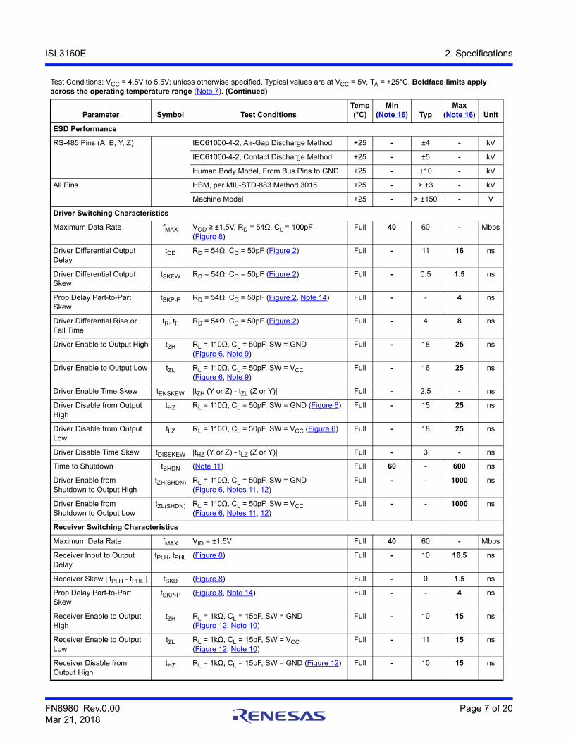
FN8980 Rev.0.00 Page 7 of 20Mar 21, 2018
ISL3160E 2. Specifications
ESD Performance
RS-485 Pins (A, B, Y, Z) IEC61000-4-2, Air-Gap Discharge Method +25 - ±4 - kV
IEC61000-4-2, Contact Discharge Method +25 - ±5 - kV
Human Body Model, From Bus Pins to GND +25 - ±10 - kV
All Pins HBM, per MIL-STD-883 Method 3015 +25 - > ±3 - kV
Machine Model +25 - > ±150 - V
Driver Switching Characteristics
Maximum Data Rate fMAX VOD ≥ ±1.5V, RD = 54Ω, CL = 100pF (Figure 8)
Full 40 60 - Mbps
Driver Differential Output Delay
tDD RD = 54Ω, CD = 50pF (Figure 2) Full - 11 16 ns
Driver Differential Output Skew
tSKEW RD = 54Ω, CD = 50pF (Figure 2) Full - 0.5 1.5 ns
Prop Delay Part-to-Part Skew
tSKP-P RD = 54Ω, CD = 50pF (Figure 2, Note 14) Full - - 4 ns
Driver Differential Rise or Fall Time
tR, tF RD = 54Ω, CD = 50pF (Figure 2) Full - 4 8 ns
Driver Enable to Output High tZH RL = 110Ω, CL = 50pF, SW = GND(Figure 6, Note 9)
Full - 18 25 ns
Driver Enable to Output Low tZL RL = 110Ω, CL = 50pF, SW = VCC(Figure 6, Note 9)
Full - 16 25 ns
Driver Enable Time Skew tENSKEW |tZH (Y or Z) - tZL (Z or Y)| Full - 2.5 - ns
Driver Disable from Output High
tHZ RL = 110Ω, CL = 50pF, SW = GND (Figure 6) Full - 15 25 ns
Driver Disable from Output Low
tLZ RL = 110Ω, CL = 50pF, SW = VCC (Figure 6) Full - 18 25 ns
Driver Disable Time Skew tDISSKEW |tHZ (Y or Z) - tLZ (Z or Y)| Full - 3 - ns
Time to Shutdown tSHDN (Note 11) Full 60 - 600 ns
Driver Enable from Shutdown to Output High
tZH(SHDN) RL = 110Ω, CL = 50pF, SW = GND(Figure 6, Notes 11, 12)
Full - - 1000 ns
Driver Enable from Shutdown to Output Low
tZL(SHDN) RL = 110Ω, CL = 50pF, SW = VCC(Figure 6, Notes 11, 12)
Full - - 1000 ns
Receiver Switching Characteristics
Maximum Data Rate fMAX VID = ±1.5V Full 40 60 - Mbps
Receiver Input to Output Delay
tPLH, tPHL (Figure 8) Full - 10 16.5 ns
Receiver Skew | tPLH - tPHL | tSKD (Figure 8) Full - 0 1.5 ns
Prop Delay Part-to-Part Skew
tSKP-P (Figure 8, Note 14) Full - - 4 ns
Receiver Enable to Output High
tZH RL = 1kΩ, CL = 15pF, SW = GND(Figure 12, Note 10)
Full - 10 15 ns
Receiver Enable to Output Low
tZL RL = 1kΩ, CL = 15pF, SW = VCC(Figure 12, Note 10)
Full - 11 15 ns
Receiver Disable from Output High
tHZ RL = 1kΩ, CL = 15pF, SW = GND (Figure 12) Full - 10 15 ns
Test Conditions: VCC = 4.5V to 5.5V; unless otherwise specified. Typical values are at VCC = 5V, TA = +25°C, Boldface limits apply across the operating temperature range (Note 7). (Continued)
Parameter Symbol Test ConditionsTemp(°C)
Min(Note 16) Typ
Max(Note 16) Unit

FN8980 Rev.0.00 Page 8 of 20Mar 21, 2018
ISL3160E 2. Specifications
Receiver Disable from Output Low
tLZ RL = 1kΩ, CL = 15pF, SW = VCC (Figure 12) Full - 10 15 ns
Time to Shutdown tSHDN (Note 11) Full 60 - 600 ns
Receiver Enable from Shutdown to Output High
tZH(SHDN) RL = 1kΩ, CL = 15pF, SW = GND(Figure 12, Notes 11, 13)
Full - - 1000 ns
Receiver Enable from Shutdown to Output Low
tZL(SHDN) RL = 1kΩ, CL = 15pF, SW = VCC(Figure 12, Notes 11, 13)
Full - - 1000 ns
Notes:7. All currents into device pins are positive; all currents out of device pins are negative. All voltages are referenced to device ground
unless otherwise specified.8. Supply current specification is valid for loaded drivers when DE = 0V.9. Because of the shutdown feature, keep RE = 0 to prevent the device from entering SHDN.
10. Because of the shutdown feature, the RE signal high time must be short enough (typically <100ns) to prevent the device from entering shutdown.
11. These ICs are put into shutdown by bringing RE high and DE low. If the inputs are in this state for less than 60ns, the parts will not enter shutdown. If the inputs are in this state for at least 700ns, the parts will enter shutdown. See “Low Power Shutdown Mode” on page 17.
12. Keep RE = VCC, and set the DE signal low time >700ns to ensure that the device enters shutdown.13. Set the RE signal high time >700ns to ensure that the device enters shutdown.14. This is the part-to-part skew between any two units tested with identical test conditions (temperature, VCC, etc.).15. VCC = 5V ±5%.16. Parts are 100% tested at +25°C. Over-temperature limits established by characterization and are not production tested.
Test Conditions: VCC = 4.5V to 5.5V; unless otherwise specified. Typical values are at VCC = 5V, TA = +25°C, Boldface limits apply across the operating temperature range (Note 7). (Continued)
Parameter Symbol Test ConditionsTemp(°C)
Min(Note 16) Typ
Max(Note 16) Unit

FN8980 Rev.0.00 Page 9 of 20Mar 21, 2018
ISL3160E 3. Test Circuits and Waveforms
3. Test Circuits and Waveforms
Figure 2. DC Driver Test Circuits VOD and VOC Figure 3. DC Driver Test Circuits VOD with Common-Mode Load
Figure 4. Driver Propagation Delay and Differential Transition Times Test Circuit
Figure 5. Driver Propagation Delay and Differential Transition Times Measurement Points
D
DE
DI
VCC
VOD
VOC
RL/2
RL/2
Z
Y
D
DE
DI
VCC
VOD
375Ω
375Ω
Z
Y
RL = 60ΩVCM
-7V TO +12V
D
DE
DI
VCC
SignalGenerator
CDRD
Z
Y
OUT (Z)
3V
0V
1.5V1.5V
VOH
VOLOUT (Y)
tPLH tPHL
DIFF Out (Y - Z)
tR
+VOD
-VOD
90% 90%
tF
10% 10%
DI
SKEW = |tPLH - tPHL|

FN8980 Rev.0.00 Page 10 of 20Mar 21, 2018
ISL3160E 3. Test Circuits and Waveforms
Figure 6. Driver Enable and Disable Times Test Circuit Figure 7. Driver Enable and Disable Times Measurement Points
Figure 8. Driver Data Rate Test Circuit Figure 9. Driver Data Rate Measurement Points
Figure 10. Receiver Propagation Delay Test Circuit Figure 11. Receiver Propagation Delay Measurement Points
D
DE
DIZ
Y
VCC
GNDSW
Parameter Output RE DI SW
tHZ Y/Z X 1/0 GND
tLZ Y/Z X 0/1 VCC
tZH Y/Z 0 (Note 9) 1/0 GND
tZL Y/Z 0 (Note 9) 0/1 VCC
tHZ(SHDN) Y/Z 1 (Note 12) 1/0 GND
tLZ(SHDN) Y/Z 1 (Note 12) 0/1 VCC
SignalGenerator
110Ω
50pF
OUT (Y, Z)
3V
0V
1.5V1.5V
VOH
0V
VOH - 0.5V
tHZ
OUT (Y, Z)
VCC
VOLVOL + 0.5V
tLZ
DE
Output High
Output Low
tZL, tZL(SHDN)
tZH, tZH(SHDN)
50%
50%
(Note 11)
(Note 11)
(Note 11)
D
DE
DI
VCC
SignalGenerator
Z
Y
VOD
+
-
54Ω
CL
CL
3V
0V
DIFF Out (Y - Z) +VOD
-VOD
DI
0V
SignalGenerator
RRO
RE
A
B+1.5V
15pF
RO
+3V
0V
tPLH
1.5V1.5V
VCC
0V
1.7V 1.7V
tPHL
A

FN8980 Rev.0.00 Page 11 of 20Mar 21, 2018
ISL3160E 3. Test Circuits and Waveforms
Figure 12. Receiver Enable and Disable Times Test Circuit
Figure 13. Receiver Enable and Disable Times Measurement Points
1kΩ VCC
GNDSW
Parameter DE A SW
tHZ 0 +1.5V GND
tLZ 0 -1.5V VCC
tZH (Note 10) 0 +1.5V GND
tZL (Note 10) 0 -1.5V VCC
tHZ(SHDN) (Note 13) 0 +1.5V GND
tLZ(SHDN) (Note 13) 0 -1.5V VCC
SignalGenerator
RRO
RE
A
BGND
15pF
RO
3V
0V
1.5V1.5V
VOH
0V
1.5VVOH - 0.5V
tHZ
RO
VCC
VOL
1.5VVOL + 0.5V
tLZ
RE
Output High
Output Low
tZL, tZL(SHDN)
tZH, tZH(SHDN)
(Note 11)
(Note 11)
(Note 11)

FN8980 Rev.0.00 Page 12 of 20Mar 21, 2018
ISL3160E 4. Typical Performance Curves
4. Typical Performance CurvesVCC = 5V, TA = +25°C; unless otherwise specified
Figure 14. Driver Output Current vs Differential Output Voltage
Figure 15. Driver Differential Output Voltage vs Temperature
Figure 16. Driver Output Current vs Short-Circuit Voltage
Figure 17. Supply Current vs Temperature
Differential Output Voltage (V)
Dri
ver
Ou
tpu
t C
urr
ent
(mA
)
0
10
20
30
40
50
60
70
80
90
100
110
0 0.5 1.0 1.5 2.0 2.5 3.0 3.5 4.0 4.5 5.0
+25°C
+85°C
+125°C
RD = 30Ω
RD = 54Ω
RD = 100Ω
RD = 20Ω
-40 -15 10 35 60 85 110
Temperature (°C)
Dif
fere
nti
al O
utp
ut
Vo
lta
ge
(V)
RD = 54Ω
RD = 100Ω
1252.5
2.6
2.7
2.8
2.9
3.0
3.1
3.2
3.3
3.4
3.5
Output Voltage (V)
-7 -6 -4 -2 0 2 4 6 8 10 12
Ou
tpu
t C
urr
ent
(mA
)
-150
-100
-50
0
50
100
150
200
Y or Z = High
Y or Z = Low
-40 -15 10 35 60 85 110 125
Temperature (°C)
I CC
(m
A)
2.30
2.35
2.40
2.45
2.50
2.55
DE = VCC, RE = X OR DE = GND, RE = GND

FN8980 Rev.0.00 Page 13 of 20Mar 21, 2018
ISL3160E 4. Typical Performance Curves
Figure 18. Driver Differential Propagation Delay vs Temperature
Figure 19. Driver Differential Skew vs Temperature
Figure 20. Driver and Receiver Waveforms Figure 21. Driver and Receiver Waveforms
VCC = 5V, TA = +25°C; unless otherwise specified (Continued)
-40 -15 10 35 60 85 110 125
Temperature (°C)
Pro
pa
gat
ion
De
lay
(n
s)
tPLH
tPHL
7.0
7.2
7.4
7.6
7.8
8.0
8.2
8.4
8.6
8.8
9.0
-40 -15 10 35 60 85 110 125
Temperature (°C)
Sk
ew
(n
s)
|tPLH - tPHL|
0.3
0.4
0.5
0.6
0.7
0.8
0.9
Time (5ns/DIV)
Re
cei
ver
Ou
tpu
t (V
)
RDIFF = 54Ω, CD = 50pF
0
5
Dri
ver
Ou
tpu
t (V
)
0
5
Dri
ver
Inp
ut
(V)
DI
RO
-3
2
3
-1
0
1
-2
Y-Z
Time (5ns/DIV)
Re
ce
ive
r O
utp
ut
(V)
RDIFF = 54Ω, CD = 50pF
0
5
Dri
ver
Ou
tpu
t (V
)
0
5
Dri
ver
Inp
ut
(V)
DI
RO
-3
-2
-1
0
1
2
3
Y-Z

FN8980 Rev.0.00 Page 14 of 20Mar 21, 2018
ISL3160E 4. Typical Performance Curves
Figure 22. Driver and Receiver Waveforms Driving 100ft (31m) of Cat 5 Cable (Double Terminated with 120Ω)
Figure 23. Driver and Receiver Waveforms Driving 350ft (107m) of Cat 5 Cable (Double Terminated with 120Ω)
Figure 24. Receiver Output Current vs Receiver Output Voltage
VCC = 5V, TA = +25°C; unless otherwise specified (Continued)
Time (10ns/DIV)-3.0
Rec
eiv
er
Ou
tpu
t (V
)
1.5
3.0
-1.5
0
0
5.0
Rec
eiv
er I
np
ut
(V)
0
5
Dri
ver
Inp
ut
(V)DI = 40Mbps
RO
Driver+cable Delay (~156ns)
A - B
Time (10ns/DIV)-3.0
Rec
eiv
er
Ou
tpu
t (V
)
1.5
3.0
-1.5
0A - B
0
5.0
Rec
eiv
er I
np
ut
(V)
0
5
Dri
ver
Inp
ut
(V)
RO
Driver+cable Delay (~480ns)
DI = 40Mbps
Receiver Output Voltage (V)
Re
ceiv
er
Ou
tpu
t C
urr
en
t (m
A)
0
10
20
30
40
50
60
70
VOH, +25°C
VOH, +85°C
VOL, +25°C
VOL, +85°C
VOH, +125°C
VOL, +125°C
0 1 2 3 4 5

FN8980 Rev.0.00 Page 15 of 20Mar 21, 2018
ISL3160E 5. Application Information
5. Application InformationRS-485 and RS-422 are differential (balanced) data transmission standards for use in long haul or noisy environments. RS-422 is a subset of RS-485, so RS-485 transceivers are also RS-422 compliant. RS-422 is a point-to-multipoint (multidrop) standard, which allows only one driver and up to 10 receivers on each bus, assuming one unit load devices. RS-485 is a true multipoint standard, which allows up to 32 one unit load devices (any mix of drivers and receivers) on each bus. To allow for multipoint operation, the RS-485 specification requires that drivers must handle bus contention without sustaining any damage.
Another important advantage of RS-485 is the extended Common-Mode Range (CMR), which specifies that the driver outputs and receiver inputs withstand signals that range from +12V to -7V. RS-422 and RS-485 are intended for cable lengths as long as 4000ft (~1200m), so the wide CMR is necessary to handle ground potential differences, as well as voltages induced in the cable by external fields.
5.1 Receiver (Rx) FeaturesThis transceiver uses a differential input receiver for maximum noise immunity and common-mode rejection. Input sensitivity is ±200mV, as required by the RS-422 and RS-485 specifications. Receiver inputs function with common-mode voltages as great as 7V outside the power supplies (that is, +12V and -7V), making them ideal for long networks, or industrial environments, where induced voltages are a realistic concern.
The receiver input resistance of 50kΩ surpasses the RS-422 specification of 4kΩ, and is five times the RS-485 “Unit Load” (UL) requirement of 12kΩ minimum. Thus, the ISL3160E is known as a “one-fifth UL” transceiver, and there can be up to 160 devices on the RS-485 bus while still complying with the RS-485 loading specification.
The receiver is a “full fail-safe” version that assures a high level receiver output if the receiver inputs are unconnected (floating), shorted together, or connected to a terminated bus with all the transmitters disabled (terminated/undriven).
Rx outputs deliver large low state currents (typically >30mA) at VOL = 1V (to ease the design of optically coupled isolated networks).
Receivers easily meet the 40Mbps data rate supported by the driver, and the receiver output is tri-statable using the active low RE input.
5.2 Driver (Tx) FeaturesThe RS-485/RS-422 driver is a differential output device that delivers at least 2.1V across a 54Ω load (RS-485), and at least 2.6V across a 100Ω load (RS-422) even with VCC = 4.5V. The drivers feature low propagation delay skew to maximize bit width and to minimize EMI.
Driver outputs are not slew rate limited, so faster output transition times allow data rates of at least 40Mbps. Driver outputs are tri-statable using the active high DE input.
For parallel applications, bit-to-bit skews between any two ISL3160E transmitter and receiver pairs are assured to be no worse than 8ns (4ns max for any two Tx, 4ns max for any two Rx).
5.2.1 High VOD Improves Noise Immunity and FlexibilityThe ISL3160E driver design delivers larger differential output voltages (VOD) than the RS-485 standard requires, or than most RS-485 transmitters can deliver. The minimum ±2.1V VOD assures at least ±600mV more noise immunity than networks built using standard 1.5V VOD transmitters.
Another advantage of the large VOD is the ability to drive more than two bus terminations, which allows use of the ISL3160E in “star” and other multiterminated, nonstandard network topologies. Figure 14 on page 12 details the transmitter’s VOD vs IOUT characteristic, and includes load lines for four (30Ω) and six (20Ω) 120Ω terminations. Figure 14 shows that the driver typically delivers 1.9/1.5V into 4/6 terminations, even at +85°C. The RS-485 standard requires a minimum 1.5V VOD into two terminations, but the ISL3160E typically delivers RS-485 voltage levels with 2 to 3 times the number of terminations.

FN8980 Rev.0.00 Page 16 of 20Mar 21, 2018
ISL3160E 5. Application Information
5.3 ESD ProtectionAll pins on the ISL3160E include Class 3 (>3kV) Human Body Model (HBM) ESD protection structures, but the RS-485 pins (driver outputs and receiver inputs) incorporate advanced structures allowing them to survive ESD events in excess of ±10kV HBM and ±5kV IEC61000-4-2. The RS-485 pins are particularly vulnerable to ESD strikes because they typically connect to an exposed port on the exterior of the finished product. Simply touching the port pins, or connecting a cable, can cause an ESD event that can destroy unprotected ICs. These new ESD structures protect the device whether or not it is powered up and without degrading the RS-485 common-mode range of -7V to +12V. This built-in ESD protection eliminates the need for board level protection structures (for example, transient suppression diodes) and the associated undesirable capacitive load they present.
5.4 Hot Plug FunctionWhen a piece of equipment powers up, a period of time occurs in which the processor or ASIC driving the RS-485 control lines (DE, RE) is unable to ensure that the RS-485 Tx and Rx outputs are kept disabled. If the equipment is connected to the bus, a driver activating prematurely during power-up may crash the bus. To avoid this scenario, the ISL3160E incorporates a “hot plug” function. Circuitry monitoring VCC ensures that the Tx and Rx outputs remain disabled during power-up and power-down, regardless of the state of DE and RE, if VCC is less than ~3.2V. This gives the processor or ASIC a chance to stabilize and drive the RS-485 control lines to the proper states.
5.5 Data Rate, Cables, and Terminations Twisted pair is the cable of choice for RS-485, RS-422, and PROFIBUS networks. Twisted pair cables tend to pick up noise and other electromagnetically induced voltages as common-mode signals, which are effectively rejected by the differential receivers in these ICs.
According to guidelines in the RS-422 and RS-485 specifications, networks operating at data rates in excess of 3Mbps should be limited to cable lengths of 100m (328ft) or less. The ISL3160E’s large differential output swing, fast transition times, and high drive-current output stages allow operation even at 40Mbps over standard “CAT5” cables in excess of 100m (328ft). Figure 23 on page 14 details the ISL3160E performance at this condition, with a 120Ω termination resistor at both the driver and the receiver ends. Note that the differential signal delivered to the receiver at the end of the cable (A-B) still exceeds 1V, so even longer cables could be driven if lower noise margins are acceptable. Of course, jitter or some other criteria may limit the network to shorter cable lengths than those discussed here. If more noise margin is desired, shorter cables produce a larger receiver input signal as illustrated in Figure 22 on page 14. Performance should be even better if using the “Type A” cable.
The ISL3160E may also be used at slower data rates over longer cables, but some limitations apply. The Rx is optimized for high speed operation, so its output may glitch if the Rx input differential transition times are too slow.
Figure 25. Hot Plug Performance (ISL3160E) vs ISL83086E without Hot Plug Circuitry
Time (40µs/DIV)
VCC
Re
ce
ive
r O
utp
ut
(V)
Dri
ver
Y O
utp
ut
(V)
2.5
5.0
2.5
5.0
VC
C (
V)
RL = 1kΩ
RO
0
2.5
5.0
0
0A/Y
RL = 1kΩ
3.1V3.3V
DE, DI = VCC
ISL3160E
ISL3160E
RE = GND

FN8980 Rev.0.00 Page 17 of 20Mar 21, 2018
ISL3160E 5. Application Information
Keeping the transition times below 500ns, (which equates to the Tx driving a 1000ft (305m) CAT 5 cable) yields excellent performance across the full operating temperature range.
To minimize reflections, proper termination is imperative when using this high data rate transceiver. In point-to-point, or point-to-multipoint (single driver on bus) networks, the main cable should be terminated in its characteristic impedance (typically 120Ω for “Cat 5” and 220Ω for “Type A”) at the end farthest from the driver. In multireceiver applications, stubs connecting receivers to the main cable should be kept as short as possible. Multipoint (multidriver) systems require that the main cable be terminated in its characteristic impedance at both ends. Stubs connecting a transceiver to the main cable should be kept as short as possible.
5.6 Built-In Driver Overload ProtectionAs stated previously, the RS-485 specification requires that drivers survive worst case bus contentions undamaged. These transmitters meet this requirement using driver output short-circuit current limits, and on-chip thermal shutdown circuitry.
The driver output stages incorporate short-circuit current limiting circuitry, which ensures that the output current never exceeds the RS-485 specification, even at the common-mode voltage range extremes. In the event of a major short-circuit condition, the device also includes a thermal shutdown feature that disables the drivers whenever the die temperature becomes excessive. This eliminates the power dissipation, allowing the die to cool. The drivers automatically reenable after the die temperature drops about 15°C. If the contention persists, the thermal shutdown/reenable cycle repeats until the fault is cleared. Receivers stay operational during thermal shutdown.
5.7 Low Power Shutdown ModeThis BiCMOS transceiver uses a fraction of the power required by its bipolar counterparts, and it includes a shutdown feature that reduces the already low quiescent ICC to a 50nA trickle. It enters shutdown whenever the receiver and driver are simultaneously disabled (RE = VCC and DE = GND) for a period of at least 600ns. Disabling both the driver and the receiver for less than 60ns assures that the transceiver will not enter shutdown.
Note that receiver and driver enable times increase when the transceiver enables from shutdown. Refer to Notes 9, 10, 11, 12, and 13 on page 8 for more information.

FN8980 Rev.0.00 Page 18 of 20Mar 21, 2018
ISL3160E 6. Revision History
6. Revision History
Rev. Date Description
0.00 Mar 21, 2018 Initial release
FN8980 Rev.0.00 Page 19 of 20Mar 21, 2018
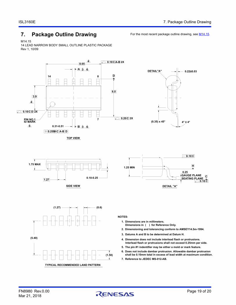
ISL3160E 7. Package Outline Drawing
7. Package Outline DrawingM14.1514 LEAD NARROW BODY SMALL OUTLINE PLASTIC PACKAGERev 1, 10/09
A
D
4
0.25 A-BM C
C
0.10 C
5 B
D
3
0.10 A-BC
4
0.20 C 2X
2X
0.10 DC 2X
H
0.10 C
6
3 6
ID MARKPIN NO.1
(0.35) x 45°
SEATING PLANEGAUGE PLANE0.25
(5.40)
(1.50)
1.27
0.31-0.51
4° ± 4°
DETAIL"A" 0.22±0.03
0.10-0.25
1.25 MIN1.75 MAX
(1.27) (0.6)
6.0
8.65
3.9
7
14 8
Dimensioning and tolerancing conform to AMSEY14.5m-1994.
Dimension does not include interlead flash or protrusions.
Dimensions in ( ) for Reference Only.
Interlead flash or protrusions shall not exceed 0.25mm per side.
Datums A and B to be determined at Datum H.
4.
5.
3.
2.
Dimensions are in millimeters.
NOTES:
1.
The pin #1 indentifier may be either a mold or mark feature.
6. Does not include dambar protrusion. Allowable dambar protrusion
7. Reference to JEDEC MS-012-AB.
shall be 0.10mm total in excess of lead width at maximum condition.
DETAIL "A"SIDE VIEW
TYPICAL RECOMMENDED LAND PATTERN
TOP VIEW
For the most recent package outline drawing, see M14.15.

http://www.renesas.comRefer to "http://www.renesas.com/" for the latest and detailed information.
Renesas Electronics America Inc.1001 Murphy Ranch Road, Milpitas, CA 95035, U.S.A.Tel: +1-408-432-8888, Fax: +1-408-434-5351Renesas Electronics Canada Limited9251 Yonge Street, Suite 8309 Richmond Hill, Ontario Canada L4C 9T3Tel: +1-905-237-2004Renesas Electronics Europe LimitedDukes Meadow, Millboard Road, Bourne End, Buckinghamshire, SL8 5FH, U.KTel: +44-1628-651-700, Fax: +44-1628-651-804Renesas Electronics Europe GmbHArcadiastrasse 10, 40472 Düsseldorf, Germany Tel: +49-211-6503-0, Fax: +49-211-6503-1327Renesas Electronics (China) Co., Ltd.Room 1709 Quantum Plaza, No.27 ZhichunLu, Haidian District, Beijing, 100191 P. R. ChinaTel: +86-10-8235-1155, Fax: +86-10-8235-7679Renesas Electronics (Shanghai) Co., Ltd.Unit 301, Tower A, Central Towers, 555 Langao Road, Putuo District, Shanghai, 200333 P. R. China Tel: +86-21-2226-0888, Fax: +86-21-2226-0999Renesas Electronics Hong Kong LimitedUnit 1601-1611, 16/F., Tower 2, Grand Century Place, 193 Prince Edward Road West, Mongkok, Kowloon, Hong KongTel: +852-2265-6688, Fax: +852 2886-9022Renesas Electronics Taiwan Co., Ltd.13F, No. 363, Fu Shing North Road, Taipei 10543, TaiwanTel: +886-2-8175-9600, Fax: +886 2-8175-9670Renesas Electronics Singapore Pte. Ltd.80 Bendemeer Road, Unit #06-02 Hyflux Innovation Centre, Singapore 339949Tel: +65-6213-0200, Fax: +65-6213-0300Renesas Electronics Malaysia Sdn.Bhd.Unit 1207, Block B, Menara Amcorp, Amcorp Trade Centre, No. 18, Jln Persiaran Barat, 46050 Petaling Jaya, Selangor Darul Ehsan, MalaysiaTel: +60-3-7955-9390, Fax: +60-3-7955-9510Renesas Electronics India Pvt. Ltd.No.777C, 100 Feet Road, HAL 2nd Stage, Indiranagar, Bangalore 560 038, IndiaTel: +91-80-67208700, Fax: +91-80-67208777Renesas Electronics Korea Co., Ltd.17F, KAMCO Yangjae Tower, 262, Gangnam-daero, Gangnam-gu, Seoul, 06265 KoreaTel: +82-2-558-3737, Fax: +82-2-558-5338
SALES OFFICES
© 2018 Renesas Electronics Corporation. All rights reserved.Colophon 7.0
(Rev.4.0-1 November 2017)
Notice
1. Descriptions of circuits, software and other related information in this document are provided only to illustrate the operation of semiconductor products and application examples. You are fully responsible for
the incorporation or any other use of the circuits, software, and information in the design of your product or system. Renesas Electronics disclaims any and all liability for any losses and damages incurred by
you or third parties arising from the use of these circuits, software, or information.
2. Renesas Electronics hereby expressly disclaims any warranties against and liability for infringement or any other claims involving patents, copyrights, or other intellectual property rights of third parties, by or
arising from the use of Renesas Electronics products or technical information described in this document, including but not limited to, the product data, drawings, charts, programs, algorithms, and application
examples.
3. No license, express, implied or otherwise, is granted hereby under any patents, copyrights or other intellectual property rights of Renesas Electronics or others.
4. You shall not alter, modify, copy, or reverse engineer any Renesas Electronics product, whether in whole or in part. Renesas Electronics disclaims any and all liability for any losses or damages incurred by
you or third parties arising from such alteration, modification, copying or reverse engineering.
5. Renesas Electronics products are classified according to the following two quality grades: “Standard” and “High Quality”. The intended applications for each Renesas Electronics product depends on the
product’s quality grade, as indicated below.
"Standard": Computers; office equipment; communications equipment; test and measurement equipment; audio and visual equipment; home electronic appliances; machine tools; personal electronic
equipment; industrial robots; etc.
"High Quality": Transportation equipment (automobiles, trains, ships, etc.); traffic control (traffic lights); large-scale communication equipment; key financial terminal systems; safety control equipment; etc.
Unless expressly designated as a high reliability product or a product for harsh environments in a Renesas Electronics data sheet or other Renesas Electronics document, Renesas Electronics products are
not intended or authorized for use in products or systems that may pose a direct threat to human life or bodily injury (artificial life support devices or systems; surgical implantations; etc.), or may cause
serious property damage (space system; undersea repeaters; nuclear power control systems; aircraft control systems; key plant systems; military equipment; etc.). Renesas Electronics disclaims any and all
liability for any damages or losses incurred by you or any third parties arising from the use of any Renesas Electronics product that is inconsistent with any Renesas Electronics data sheet, user’s manual or
other Renesas Electronics document.
6. When using Renesas Electronics products, refer to the latest product information (data sheets, user’s manuals, application notes, “General Notes for Handling and Using Semiconductor Devices” in the
reliability handbook, etc.), and ensure that usage conditions are within the ranges specified by Renesas Electronics with respect to maximum ratings, operating power supply voltage range, heat dissipation
characteristics, installation, etc. Renesas Electronics disclaims any and all liability for any malfunctions, failure or accident arising out of the use of Renesas Electronics products outside of such specified
ranges.
7. Although Renesas Electronics endeavors to improve the quality and reliability of Renesas Electronics products, semiconductor products have specific characteristics, such as the occurrence of failure at a
certain rate and malfunctions under certain use conditions. Unless designated as a high reliability product or a product for harsh environments in a Renesas Electronics data sheet or other Renesas
Electronics document, Renesas Electronics products are not subject to radiation resistance design. You are responsible for implementing safety measures to guard against the possibility of bodily injury, injury
or damage caused by fire, and/or danger to the public in the event of a failure or malfunction of Renesas Electronics products, such as safety design for hardware and software, including but not limited to
redundancy, fire control and malfunction prevention, appropriate treatment for aging degradation or any other appropriate measures. Because the evaluation of microcomputer software alone is very difficult
and impractical, you are responsible for evaluating the safety of the final products or systems manufactured by you.
8. Please contact a Renesas Electronics sales office for details as to environmental matters such as the environmental compatibility of each Renesas Electronics product. You are responsible for carefully and
sufficiently investigating applicable laws and regulations that regulate the inclusion or use of controlled substances, including without limitation, the EU RoHS Directive, and using Renesas Electronics
products in compliance with all these applicable laws and regulations. Renesas Electronics disclaims any and all liability for damages or losses occurring as a result of your noncompliance with applicable
laws and regulations.
9. Renesas Electronics products and technologies shall not be used for or incorporated into any products or systems whose manufacture, use, or sale is prohibited under any applicable domestic or foreign laws
or regulations. You shall comply with any applicable export control laws and regulations promulgated and administered by the governments of any countries asserting jurisdiction over the parties or
transactions.
10. It is the responsibility of the buyer or distributor of Renesas Electronics products, or any other party who distributes, disposes of, or otherwise sells or transfers the product to a third party, to notify such third
party in advance of the contents and conditions set forth in this document.
11. This document shall not be reprinted, reproduced or duplicated in any form, in whole or in part, without prior written consent of Renesas Electronics.
12. Please contact a Renesas Electronics sales office if you have any questions regarding the information contained in this document or Renesas Electronics products.
(Note 1) “Renesas Electronics” as used in this document means Renesas Electronics Corporation and also includes its directly or indirectly controlled subsidiaries.
(Note 2) “Renesas Electronics product(s)” means any product developed or manufactured by or for Renesas Electronics.