ISESCO JOURNAL of Science and Technologyisesco.org.ma/ISESCO_Technology_Vision/NUM17/doc/11.pdf ·...
15
77 ISESCO JOURNAL of Science and Technology Volume 10 - Number 17 - May 2014 (77-91) Abstract T his paper investi- gates the develop- ment of a preliminary design method for centri- fugal compressors. The design process starts with the aerodynamic analysis of the preliminary design and its reliance on em- pirical rules limiting the main design parameters. The procedure is applied to compressors for pressure ratios of 1.5, 3 and 5 as an example for developing an initial non-dimensional skeleton design. The skeleton diagrams are presented for different exit blade angles ranging from 0° to -60°. The design procedure was carried out for three cases: without prewhirl and with high positive prewhirl of 15° and 30°. Design considerations of mechanical stress for the impeller and mini- mum inlet relative Mach number are taken into consideration. Diffusion factor limitations have also been considered. Selected design parameters according to economical conside- rations have been presented for each pressure ratio. Keywords: Blade angle, Centrifugal compressor, Dif- fusion factor, Inlet Mach number. Design Procedure of Centrifugal Compressors Adnan Hamza Zahed 1 and Nazih Noaman Bayomi 1,2 1 King Abdulaziz University, Jeddah, Kingdom of Saudi Arabia 2 Faculty of Engineering El-Mattaria, Helwan University, Cairo, Egypt E-mail: [email protected] 1. Introduction The design of a centrifugal compressor is constrained by a number of non-aerodynamic considerations. These include cost, overall frame size, inertia of the rotating components and general durability. Obtaining high pressure ratios through increased impeller tip speeds dictates the use of titanium metal instead of aluminum, which generates an increase in cost. Current requirements are however for pressure ratios that can be achieved at rotational speeds suitable for aluminum impellers, and the need to switch to alternative material is not yet overwhelming. If the impeller tip speed is considered to be limited by stress considerations, the increase in pressure ratio can only be achieved by reducing the magnitude of the impeller blade back- sweep. This will lead to a reduction in operating range which could possibly be recovered through the application of a positive swirl at the impeller inlet. In the absence of the ability to increase blade tip speeds, this will in turn create the need to further reduce the blade backsweep in order to achieve the desired pressure ratio. Consequently the application of an inlet prewhirl can be considered in order to reduce the inlet relative Mach number and increase the compressor operating range. The effect of extended front and backward-swept shrouded impellers on the performance of centrifugal compressors with vaneless diffusers was investigated by Sapiro [1]. Japikse and Osborne [2 & 3] introduced an overall performance and a test procedure for the optimization of industrial centrifugal compressors. The results of detailed interstage measurements were presented and the diffusion levels with the compressor components were quantified. A review of some of the theoretical and experimental techniques used in the aerodynamic development of standard stages for
Transcript of ISESCO JOURNAL of Science and Technologyisesco.org.ma/ISESCO_Technology_Vision/NUM17/doc/11.pdf ·...

77
ISESCO JOURNAL of Science and TechnologyVolume 10 - Number 17 - May 2014 (77-91)
Abstract
This paper investi-gates the develop-
ment of a preliminary design method for centri-fugal compressors. The design process starts with the aerodynamic analysis of the preliminary design and its reliance on em-pirical rules limiting the main design parameters. The procedure is applied to compressors for pressure ratios of 1.5, 3 and 5 as an example for developing an initial non-dimensional skeleton design. The skeleton diagrams are presented for different exit blade angles ranging from 0° to -60°.
The design procedure was carried out for three cases: without prewhirl and with high positive prewhirl of 15° and 30°. Design considerations of mechanical stress for the impeller and mini-mum inlet relative Mach number are taken into consideration. Diffusion
factor limitations have also been considered. Selected design parameters according to economical conside-rations have been presented for each pressure ratio.
Keywords: Blade angle, Centrifugal compressor, Dif-fusion factor, Inlet Mach number.
Design Procedure ofCentrifugal Compressors
Adnan Hamza Zahed1
and Nazih Noaman Bayomi1,2
1King Abdulaziz University,Jeddah, Kingdom of Saudi Arabia
2Faculty of Engineering El-Mattaria, Helwan University, Cairo, Egypt E-mail: [email protected]
1. Introduction
The design of a centrifugal compressor is constrained by a number of non-aerodynamic considerations. These include cost, overall frame size, inertia of the rotating components and general durability. Obtaining high pressure ratios through increased impeller tip speeds dictates the use of titanium metal instead of aluminum, which generates an increase in cost. Current requirements are however for pressure ratios that can be achieved at rotational speeds suitable for aluminum impellers, and the need to switch to alternative material is not yet overwhelming. If the impeller tip speed is considered to be limited by stress considerations, the increase in pressure ratio can only be achieved by reducing the magnitude of the impeller blade back-sweep. This will lead to a reduction in operating range which could possibly be recovered through the application of a positive swirl at the impeller inlet. In
the absence of the ability to increase blade tip speeds, this will in turn create the need to further reduce the blade backsweep in order to achieve the desired pressure ratio. Consequently the application of an inlet prewhirl can be considered in order to reduce the inlet relative Mach number and increase the compressor operating range.
The effect of extended front and backward-swept shrouded impellers on the performance of centrifugal compressors with vaneless diffusers was investigated by Sapiro [1]. Japikse and Osborne [2 & 3] introduced an overall performance and a test procedure for the optimization of industrial centrifugal compressors. The results of detailed interstage measurements were presented and the diffusion levels with the compressor components were quantified. A review of some of the theoretical and experimental techniques used in the aerodynamic development of standard stages for

A.H. Zahed and N.N. Bayomi / ISESCO Journal of Science and Technology - Volume 10, Number 17 (May 2014) (77-91)
78
industrial centrifugal compressors was presented by Dalbert et al. [4]. Design methods for standardized families of radial compressor stages were summarized. A simple method for designing the blade geometry of a centrifugal compressor impeller was presented by Wang et al. [5]. In this method, instead of giving the mean swirl distribution on the meridional surface, the blade angle distribution was specified and the blade shape was derived, making it easier to execute the design.
In spite of the variations in size, duty and design emphasis, much of the science and understanding that support the aerodynamic and mechanical design of centrifugal compressors are common to all types. Thus, Came and Robinson [6] introduced the aerodynamic design of the centrifugal compressor by computational fluid dynamics (CFD), while Pourfarzaneh et al., [7] introduced a new analytical model of a centrifugal compressor.
Dalbert et al. [8] described the special design features of a radial compressor and shed light on a method of standardization to overcome the large diversity of machine types. Their paper reviews the aerodynamic and thermodynamic aspects in the design of an impeller with an exit blade angle of up to 75°. Also, Schiffmann & Favrat [9] manage the optimizing of the compressor design into the possible specifications field while keeping high efficiency on a wide operating range.
Whitfield et al. [10] studied the compressor performance using an inlet guide vane (IGV), with angles varying from -20° to 20° and cambered blades with discharge angle changes from β2= -5° to 35°. The results showed clearly that the improvement in flow range and the isentropic efficiency penalties are considered. In Simon et al. [11] found that the operating range of centrifugal flow compressors with backward curved impeller blades, β2= 50° and 65°, could be extended with IGV and diffuser vanes. Also, Rodgers [12] and Coppinger & Swain [13] concluded that the stable operating range of centrifugal compressors extended by the regulation of the IGV and increased impeller stability. In [14], Whitfield et al. showed that the application of a 55° prewhirl causes a distinct shift in the surge point of the
centrifugal compressor to lower flowrates compared with a zero prewhirl. Kassens and Rautenberg [15] tested a centrifugal compressor with adjustable IGV with different adjustment angles at -30°, 0°, 30° and 60°. Abdel Hafiz and Bayomi [16] described a procedure for the design of centrifugal compressor impellers. The design procedure has been applied to compressors with moderate pressure ratios. In this work, the effect of the inlet prewhirl on the compressor maps is taken into consideration only for a pressure ratio of 6 for a certain exit blade angle -30°.
The present paper describes the design of centrifugal compressors with three different pressure ratios of 1.5, 3 and 5. The preliminary design of impeller dimensions and impeller aerodynamics are presented. The design procedure depends on a nondimensional method and introduces a simple skeleton for the preliminary design of the impeller. The impeller blade angle varied from radially blade to high lean backward with an angle of -40° and -60°. In addition, an inlet prewhirl is introduced varying from 0° to 30° according to aerodynamic design and stress considerations. The diffusion ratio through the impeller is taken into consideration.
2. Consideration of the preliminary design
2.1 Importance of the preliminary design
The aim of the preliminary design can be simply stated as the desire to achieve the design duty on a one-dimensional basis, within the mechanical limitations of available material and with the best achievable efficiency and surge margin. This can be expanded into the following more specific aims: at the design mass flow, or nominal point mass flow, to achieve the desired work input, the desired efficiency, the desired pressure ratio and sufficient surge margin.
2.1.1 Work input
The main components of a centrifugal compressor are shown in Figure 1. Velocity triangles at inlet and exit of the compressor for radial blades and leaned blades with states of the prewhirl are also plotted in Figure 1.

A.H. Zahed and N.N. Bayomi / ISESCO Journal of Science and Technology - Volume 10, Number 17 (May 2014) (77-91)
79
The work input to the compressor is usually expressed as the work input factor or stage loading:
In this equation, the second term of the RHS (right hand side) is known as the slip velocity ratio. It is expressed by Wiesner [17] as
Where Z is the number of blades. The third term includes the ratio of the flow velocity in the radial direction, Cr2 and the impeller speed, U2, known as the flow coefficient j and the exit blade angle β
∞2. The
relation between the work factor and the blade exit angle for different flow coefficients for an impeller of 16 blades is shown in Figure 2. From this figure, it can be deduced that the work factor is reduced at higher values of exit blade angle depending on the velocity ratio Cr2/U2. The work factor is reduced as the flow ratio increases. The work factor also determines the impeller tip speed and consequently the impeller stress levels. The stage pressure ratio obtained from a given tip speed is represented by the equation:
The parameter λ = ΔH/(U2)2 = Cu2/U2 = m/[1-(tan β2/tan
α2) is often refereed to as the work input coefficient or work factor (Rodgers [12]). Also, the rotational speed is expressed by the “tip speed Mach number” or “stage Mach number”, relating the tip speed U2 to the inlet speed of sound:
For any specified pressure ratio, the impeller non-dimensional tip speed Mu2 follows directly from the equation (3). Alternatively, Mu2 can be systematically varied to cover a range of pressure ratios. The discharge
Mach number M2, known as C2/a2 can be developed to the following expression:
2.1.2 Compressor efficiency
Generally, a centrifugal compressor is required to pro-duce a specified pressure ratio at maximum efficiency. The desire to achieve maximum efficiency may be compromised in order to meet other design restraints such as minimizing overall size and weight and maximizing the flowrate between surge and choke. There is a specific non-dimensional flowrate θ at a certain non-dimensional speed Mu2 where maximum efficiency will be achieved. The non-dimensional mass flowrate, θ, can be expressed as
Figure 1. Main component of a centrifugal compressor withvelocity triangles at inlet and exit.
(1)
(2)
(3)
(4)
Figure 2. Effect of the exit blade angle on the work factor fordifferent flow coefficients.
(5)
(6)

A.H. Zahed and N.N. Bayomi / ISESCO Journal of Science and Technology - Volume 10, Number 17 (May 2014) (77-91)
80
The designer must establish these parameters and then develop the overall geometry of the impeller. The design procedure will be developed beginning from the desired pressure ratio, with specified target efficiencies for the impeller and the complete stage. The impeller efficiency is required to effectively transform the desired stage pressure ratio to that required from the impeller only. However, the desire to maximize this efficiency will be maintained. In addition to establishing the optimum non-dimensional mass flowrate and impeller speed, the non-dimensional geometry of the impeller will be developed in terms of the radius ratio, r1s/r2, the discharge height, b2/r2, and the inlet and discharge blade angles.
In fact, to maximize efficiency, it is necessary to minimize loss. Whilst losses are not explicitly calculated through the application of loss models, it is essential to assess the consequences of any design choice on loss generating processes. For the impeller, the losses commonly considered are aerodynamic and parasitic losses. The aerodynamic losses and the sequence required for minimizing them are as follows:
1. Incidence loss which is dependent on the magnitude and direction of the relative Mach number at the impeller inlet. To minimize the incidence effect, the relative Mach number should be minimized and a suitable blade leading edge selected.
2. Friction loss in blade passage: To attain better efficiencies, smooth surfaces, low velocity levels and wide but not too long flow channels should be taken into consideration. To minimize the relative Mach numbers, there should be a plan to decrease the inlet relative gas velocity. Also, the flow path length and the magnitude of the effective hydraulic diameter of the passage must obligatorily be taken into consideration.
3. Diffusion or blade loading loss in both the impeller and the diffuser of the compressor constitute another form loss since a high pressure rise in a stage automatically implies a high deceleration of the flow in the stage.
4. Clearance loss is due essentially to the gap between the tips of the rotating blades and the stationary shroud. Therefore, the clearance gap should be minimized as much as possible. The proportion of the flow passage occupied by the clearance gap will increase as the actual blade height is reduced, hence the necessity to assess the magnitude of the non-dimensional blade height, b2/r2.
5. Diffuser system loss: The high discharge Mach number M2 from the impeller must be diffused. It is therefore important to ensure that the discharge Mach number is not higher than necessary.
Parasitic losses include the disc friction over the hub and shroud disc and losses in connection with the leakage over the hub and shroud labyrinth seals. It was found that the loss rates are independent of the Reynolds number and became minimal at a certain flow coefficient.
The essential aim of the design procedure is to establish the optimum velocity triangles at the inlet to and discharge from the impeller. Specifying and systematically varying the absolute and relative flow angles achieves this. The case of swirl-free flow at the inlet is considered here and the absolute flow angle at the impeller inlet is zero. In the case of the absolute flow angle at the impeller discharge, Johnston and Dean [19] showed that an optimum flow angle α2, for design pressure, lies between 63°to 68°. Similarly, Rodgers and Sapiro [20] considered the optimum flow angle to lie between 60° and 70°. Osborne et al. [21] used a magnitude of 70° in the design of an 8:1 pressure ratio compressor, whilst for a 6.5:1 pressure ratio compressor, Came [22] indirectly used a magnitude of 75°. Came and Robinson [6] found a range of 69°<α2<73° to provide acceptable limits to the compressor design. For the illustrative examples used here, an absolute flow angle of 65° will generally be adopted with an assessment made of the application of alternative magnitudes. Through the desired stage pressure ratio and target efficiency, the non-dimensional speed of the impeller U2/a01, can be found and the velocity triangles

A.H. Zahed and N.N. Bayomi / ISESCO Journal of Science and Technology - Volume 10, Number 17 (May 2014) (77-91)
81
established. The impeller radius ratio, r1s/r2, then follows from the derived blade speeds at the impeller inlet and discharge. The impeller target efficiency must then be introduced to calculate the impeller discharge blade height, b2/r2.
Rodgers [23] presented the relation of specific speed and efficiency. This relation showed that at a low specific speed, efficiency drops owing to increasing frictional losses in the longer, lower aspect ratio vane passages and owing to increasing disc friction. At high specific speed, increased aerodynamic losses result from the higher relative velocity levels. The expression of specific speed can be defined as follows:
Application of the continuity condition at impeller inlet leads to the non-dimensional mass flowrate at impeller inlet (see Whitfield and Baines [24]), as
The impeller non-dimensional mass flowrate, θ, is related to that at inlet, θ1, through [θ π (r2)2] = [θ2 π (r1s)
2 ] (1-ν2) cos α1 and equation (9) can be developed from equation (8) as:
Where ν is impeller inducer hub-shroud radius ratio. This expression was solved for the absolute Mach number, M1s, through the specification of a range of non-dimensional mass flowrates and impeller radius ratios. The impeller width ratio (b2, r2) can be calculated from the following equation:
where hI is the impeller efficiency and equal to 80%.
3. Impeller design considerations
The non-dimensional speed of the impeller (tangential Mach number Mu2) for a range of blade backsweep angles (0 to -60°) together with the discharge Mach number M2 are shown in Figure 3 using equations 3 and 5. The efficiency is assumed to be 80% and α
2 =65° for a pressure ratio ranging from 1.5 to 5. The
clear advantage of the blade backward is illustrated through the reduction in the discharge Mach number of the fluid. This is accompanied by an increase in the non-dimensional speed of the impeller, which leads to an increase in the stress levels. The results obtained by Whitfield [25] and Abdel Hafiz and Bayomi [16] for pressure ratios 2, 3, 4 and 6 are also presented in Figure 3 for comparison. Good agreements in trends are shown between the present results and the other authors’ results.
In the following investigation, the design procedure is applied to pressure ratios of 1.5, 3 and 5. The pressure ratio 1.5 is a low-pressure ratio that is perhaps typical for turbocharger compressors. The other pressure ratios are more typical of those required for small gas turbines.
Relations between the non-dimensional impeller speed, Mu2, and inlet relative Mach number, M1rel, for different blade angles and different radius ratios r1s/r2 ranging from 0.4 to 0.9 are computed using equation (11) for the different pressure ratios.
(7)
(8)
(9) Figure 3. Relation between discharge Mach number andtangential blade Mach number with various exit blade angles
and different pressure ratios
(10)

A.H. Zahed and N.N. Bayomi / ISESCO Journal of Science and Technology - Volume 10, Number 17 (May 2014) (77-91)
82
The typical plot for a pressure ratio of 1.5 is presented in Figure 4 taking an inlet relative flow angle, β1s=-60°. This was carried out for a radial blade i.e. β2 = 0° up to high exit blade angle β2=-40° and -60°. It can be concluded that increasing the blade backsweep β2 and the accompanying increase in non-dimensional impeller speed Mu2 leads to an increase in the inlet relative Mach number for any specified radius ratio. In order to decrease the inlet relative Mach number, the impeller radius ratio has to be reduced. This means a larger sized impeller. If the designer is free to select the non-dimensional impeller speed, then a range of impeller radius ratios and blade backsweep are available. Increasing the blade backsweep has a beneficial effect on the impeller discharge M2 as shown in Figure 3. Whitfield and Baines [24] showed that the inlet absolute and relative Mach numbers are related to the mass flowrate per unit frontal area through this equation:
This equation, together with equation (9), is used to represent the aerodynamic characteristics in relation to the corresponding impeller dimensions for different pressure ratios.
3.1 Design impeller for 1.5 pressure ratio
In Figure 5, the contours of the non-dimensional mass flowrate and inlet relative flow angle are plotted as a function of the inducer Mach number for discharge blade angles of 0°, -40° and -60°. These results are presented for an inducer hub-tip radius ratio, ν =0.4. Aerodynamically, the optimum hub-tip radius ratio is the smallest possible ratio that presents a minimum blockage to the flow.
The inlet relative flow angle, β1s , is a function of the inlet relative Mach number as shown by Stanitz [26] in the following equation:
Lines of constant β1s of -50°, -60°, -70° and -80° are superimposed in the diagram of Figure 5. In addition, contours of impeller radius ratio are also presented as derived from the following definition of the non-dimensional mass flow rate,
The results provided in Figures 3, 4 & 5 represent design data for the designer to specify the initial impeller skeleton dimensions. The values of the non-dimensional mass flowrate corresponding to a specific speed and blade height ratios b2/r2 are also tabulated in Figure 5. The non-dimensional mass flowrate for these compressors lies typically between 0.05 and 0.20 and this corresponds to an accepted range for corresponding specific speed.
Selection of the non-dimensional mass flowrate with the minimum relative Mach number condition leads to the basic impeller dimensions r1s/r2 and b2/r2 for any selected discharge blade angle. The adoption of the blade backsweep leads to a reduction in the discharge Mach number and an increase in the inlet relative Mach number, M1rel. However, the degree of backsweep is probably limited in most cases to avoid stress considerations.
(11)
(12)
Figure 4. Variation of inlet relative Mach number with tangential blade Mach number with various exit blade angle and different
impeller radius ratios at a pressure ratio of 1.5.
(13)
(14)

A.H. Zahed and N.N. Bayomi / ISESCO Journal of Science and Technology - Volume 10, Number 17 (May 2014) (77-91)
83
With an increasing blade backsweep, it is necessary to reduce the non-dimensional flowrate in order to avoid increased relative Mach numbers at the inlet. In order to reduce the inlet relative Mach number, the radius ratio is reduced and consequently the non-dimensional blade height ratio b2/r2 decreases, leading to a long narrow discharge passage. The diagrams are repeated for a prewhirl of 15° and 30°. It is observed that the inlet relative Mach number decreases with increasing prewhirl.
3.2 Design impeller for a pressure ratio of 3
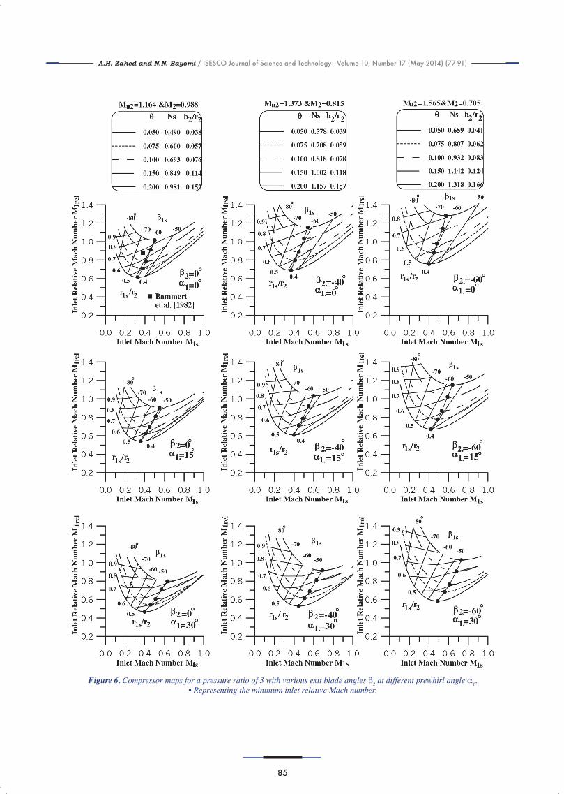
Similar diagrams are built for a pressure ratio of 3 in Figure 6. Similar trends are noticed as described from Figure 5. The design point of the centrifugal compressor tested by Bammart et al. [27] for a pressure ratio of 2.9 is plotted on the same figure. This design point has the following characteristic: b2/r2=0.13, r1s/r2=0.7 and =63°. A small shift can be noted from the lines of r1s/r2=0.7 due to the decreased pressure ratio.
3.3 Design impeller for a pressure ratio of 5
Contours of the non-dimensional mass flowrate for a pressure ratio of 5 are shown in Figure 7. Selection of the minimum relative Mach number leads to the inlet relative flow angle, β1s and the appropriate non-dimensional mass flowrate. In fact, the selection of a low non-dimensional flowrate will lead to a long narrow flow channel through low magnitudes for the impeller radius ratio and blade height. High magnitudes of θ, 0.1 and above will lead to high inlet relative Mach numbers in excess of unity, but no other clear disadvantages. In the case of a high backsweep, 60°, we note a drastic increase in M1rel for the whole range of θ at zero prewhirl.
In fact, for high-pressure ratio compressors a clear choice exists with respect to the impeller design. The inlet relative Mach number can be minimized by reducing the radius ratio, thereby designing a long narrow impeller discharge passage which will lead to increased friction and shroud leakage
losses together with additional friction loss on the impeller back face.
The results withdrawn from the above investigation show the same trend as found in the literature, whereas Rodgers [28] showed that the optimum specific speed increases as the blade backsweep increases. Also, the optimum specific speed for a given discharge blade angle decreases with an increasing Mach number, that is with an increasing pressure ratio. In Figures 5, 6 & 7 the lines connecting the closed circles represent the non-dimensional mass flowrate at the minimum inlet relative Mach number.
4. Design assessment
Rodgers [29] listed the most important design parameters as specific speed, Mach numbers, diffusion limitations and exit flow angle. The investigation of Whitfield and Baines [24] showed that the Mach numbers and exit flow angles have been employed extensively, and the specific speed and diffusion limitations remained as parameters, which can be readily calculated to further assess the design. To further assess the compressor design, many authors (as example, Rodgers [29] and Engeda [30]) have discussed the internal diffusion limitations. The overall diffusion ratio, DR, can be calculated from the next equation:
This expression shows the diffusion ratio as a function of blade angle whereas λ=m/[1-(tan β2/tan α2). A maximum DR occurs when λ=sin2 α2; however, with an assumed slip factor of 0.85 this maximum usually occurs at exit blade angles ≈-5° (with m=0.85 and α2 =65°) (Whitfield and Baines [24]). Clearly, the magnitude of DR is a direct function of the radius ratio r1s/r2 and while high diffusion rates are desirable, a boundary layer separation will occur and high predicted diffusion rates may be achieved in practice.
(15)

A.H. Zahed and N.N. Bayomi / ISESCO Journal of Science and Technology - Volume 10, Number 17 (May 2014) (77-91)
84
Figure 5. Compressor maps for a pressure ratio of 1.5 with various exit blade angles β2 at different prewhirl angles α1.• Representing the minimum inlet relative Mach number.
A.H. Zahed and N.N. Bayomi / ISESCO Journal of Science and Technology - Volume 10, Number 17 (May 2014) (77-91)
85
Figure 6. Compressor maps for a pressure ratio of 3 with various exit blade angles β2 at different prewhirl angle α1.• Representing the minimum inlet relative Mach number.

A.H. Zahed and N.N. Bayomi / ISESCO Journal of Science and Technology - Volume 10, Number 17 (May 2014) (77-91)
86
Figure 7. Compressor maps for pressure a ratio of 5 with various exit blade angles β2 at different prewhirl angles α1.• Representing the minimum inlet relative Mach number.

A.H. Zahed and N.N. Bayomi / ISESCO Journal of Science and Technology - Volume 10, Number 17 (May 2014) (77-91)
87
Another expression for internal diffusion limi-tations was used by many other authors such as Whitfield [25], Abdel Hafiz & Bayomi [16] and Biba & Menegay [31] to evaluate the design parameter of the compressor impeller and it is known as the diffusion factor. This factor is defined as the ratio of the exit relative velocity to the inlet relative velocity W2/W1 or M2rel/M1rel and is calculated from the following equation:
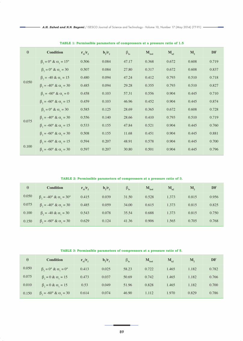
This ratio, also known as de Haller ratio (Wilson and Korakianitis [32]), was accepted only through the range from 0.7 to 0.95. The diffusion factors were calculated using equation (14) for the selected cases with minimum inlet relative Mach number and are plotted in Figure 8 for the different pressure ratios. From this figure, it can be deduced that as the inlet relative Mach number increases the diffusion factor decreases. An increase in prewhirl angle for a certain exit blade angle causes the diffusion factor to increase. Limitations for the diffusion factor are plotted as the discrete lines on Figure 8. A flow-chart for the design process is presented in Figure 9. Consequently, different cases within this permissible range are tabulated according to the required non-dimensional mass flowrate in Table 1 for the pressure ratio 1.5 as an example. From this table, an optimum design is selected based on the requirement to achieve the specific mass flowrate at this pressure ratio according to economical considerations i.e. impeller size and simplicity in manufacturing.
It can be noted from Table 1 that the selected cases correspond to the non-dimensional mass flowrate, q, ranging only between 0.05 and 0.1. The most economical designs are corresponding to an acceptable specific speed range, Ns. Radial blades with a prewhirl 15 correspond to q =0.05 and 30 for q =0.075. For a higher non-dimensional mass
flowrate up to 0.1, a leaned blade up to -60 with a prewhirl of 15 is the most suitable design.
This procedure is repeated for the different pres-sure ratios and permissible ranges are tabulated in Tables 2 and 3 for pressure ratios 3 and 5, respectively. As the pressure ratio increases to 3, radial blades lead to an almost sonic discharge Mach number, this is why a leaned blade of -40 is preferable. A prewhirl 30 will decrease the inlet relative Mach number, M1rel. This is true for a non-dimensional flowrate of up to 0.1. For a higher non-dimensional flowrate of up to 0.15, a leaned blade angle of -60 associated with the same prewhirl is recommended. Table 2 summarizes these results.
Figure 8. Diffusion factors against minimum inlet relative Mach number for different exit blade angle and prewhirl angle
at different pressure ratios.
(16).

A.H. Zahed and N.N. Bayomi / ISESCO Journal of Science and Technology - Volume 10, Number 17 (May 2014) (77-91)
88
Figure 9. Flow-chart for the design process of centrifugal compressors.
A.H. Zahed and N.N. Bayomi / ISESCO Journal of Science and Technology - Volume 10, Number 17 (May 2014) (77-91)
89
TABLE 1: Permissible parameters of compressors at a pressure ratio of 1.5
θ
β2 = 0° & α1 = 15°
β2 = 0° & α1 = 30
β2 = -40 & α1 = 15
β2 = -40° & α1 = 30
β2 = -60° & α1 = 0
β2 = -60° & α1 = 15
β2 = 0° & α1 = 30
β2 = -40° & α1 = 30
β2 = -60° & α1 = 15
β2 = -60° & α1 = 30
β2 = -60° & α1 = 15
β2 = -60° & α1 = 30
Condition
0.506
0.507
0.480
0.485
0.458
0.459
0.585
0.556
0.533
0.508
0.594
0.597
r1s/r2
0.084
0.084
0.094
0.094
0.103
0.103
0.125
0.140
0.155
0.155
0.207
0.207
b2/r2
47.17
27.80
47.24
29.28
57.31
46.96
28.69
28.66
47.84
11.68
48.91
30.80
β1s
0.368
0.317
0.412
0.355
0.556
0.452
0.365
0.410
0.521
0.451
0.578
0.501
M1rel
0.672
0.672
0.793
0.793
0.904
0.904
0.672
0.793
0.904
0.904
0.904
0.904
Mu2
0.608
0.608
0.510
0.510
0.445
0.445
0.608
0.510
0.445
0.445
0.445
0.445
M2
0.719
0.837
0.718
0.827
0.710
0.874
0.728
0.719
0.760
0.881
0.700
0.796
DF
0.050
0.075
0.100
TABLE 2: Permissible parameters of compressors at a pressure ratio of 3.
θ
β2 = -40° & α1 = 30°
β2 = -40° & α1 = 30
β2 = -40 & α1 = 30
β2 = -60° & α1 = 30
Condition
0.415
0.485
0.543
0.629
r1s/r2
0.039
0.059
0.078
0.124
b2/r2
31.50
34.00
35.54
41.36
β1s
0.528
0.615
0.688
0.906
M1rel
1.373
1.373
1.373
1.565
Mu2
0.815
0.815
0.815
0.705
M2
0.956
0.825
0.750
0.768
DF
0.050
0.075
0.100
0.150
TABLE 3: Permissible parameters of compressors at a pressure ratio of 5.
θ
β2 = 0° & α1 = 0°
β2 = 0 & α1 = 15
β2 = 0 & α1 = 15
β2 = -60° & α1 = 30
Condition
0.413
0.473
0.53
0.614
r1s/r2
0.025
0.037
0.049
0.074
b2/r2
58.23
50.69
51.96
46.90
β1s
0.722
0.742
0.828
1.112
M1rel
1.465
1.465
1.465
1.970
Mu2
1.182
1.182
1.182
0.829
M2
0.782
0.766
0.700
0.786
DF
0.050
0.075
0.010
0.150
A.H. Zahed and N.N. Bayomi / ISESCO Journal of Science and Technology - Volume 10, Number 17 (May 2014) (77-91)
90
For a pressure ratio of 5, at a 0.05 low non-dimensional mass flowrate, the radial blade with no prewhirl leads to favorable conditions. As the non-dimensional mass flowrate increases to 0.1, radial blades accompanied with a prewhirl of 15° can satisfy the different requirements of economical design and good operation. For a higher non-dimensional mass flowrate up to 0.15, a high backsweep angle of up to -60° with a prewhirl of 30° is recommended, as shown in Table 3.
Further assessment of the proposed design has to be made by predicting a complete performance map using suitable empirical loss models and correlations. If the predicted performance does not meet the requirements, it may be necessary to return to the preliminary design procedure
described above in order to reassess the design. It was found that the main parameters could only be varied within a very limited range. The assumed slip factor and efficiency play an essential part in the determination of the degree of backsweep adopted.
There are many sources of loss in a centrifugal compressor, classified as aerodynamic and para-sitic losses. For the aerodynamic losses there are several sources, which are more or less important depending on the value of the flow coefficient. Neglecting less important effects such as blade curvature, rotational speed or shape of the flow channels, the aerodynamic losses in the design point of a centrifugal compressor depend on friction losses and other factors as explained above.
Conclusion
This paper has underlined the essential integration of impeller structural analysis in the main design iteration so that a fully optimized aeromechanic design can be achieved. Different aerodynamic and design aspects of the impeller have been analyzed and limitations of the main parameters have been given. The following conclusions were drawn leading to a preliminary design for the different cases:
1. At a low-pressure ratio, 1.5, the non-dimensional mass flowrate, θ, is limited only to 0.1. At a low non-dimensional mass flowrate, radial blades with a prewhirl of 15° are selected and corresponding values of r1s/r2 =0.506 and b2/r2=0.084. The prewhirl is increased to 30° for a medium non-dimensional mass flowrate. A slight increase in r1s/r2 leads to 0.585 and similar increase in b2/r2=0.125. As the flowrate increases, a leaned blade with 60° accompanied with a prewhirl of 15° is the most suitable design with r1s/r2 =0.594 and b2/r2=0.207. This means a more compact design.
2. At a pressure ratio of 3, a backsweep angle of 40° with a prewhirl of 30° is recommended for impeller design for the non-dimensional mass flowrate, θ of up to 0.1. The backsweep angle increases to 60° as the non-dimensional mass flowrate, θ, increases. Corresponding design parameters are selected from Table (2).
3. As the pressure ratio increases to 5, the operating range of non-dimensional mass flowrate increases to 0.15.
4. At a pressure ratio of 5, at a low non-dimensional mass flowrate, θ, radial blades with no prewhirl were found to be the most suitable. With an increase in the non-dimensional mass flowrate of up to 0.1, a prewhirl of 15° is necessary. As θ increases, a backsweep of 60° with a prewhirl of 30° is recommended. Table (3) provides the corresponding design ratio r1s/r2 and b2/r2.
A.H. Zahed and N.N. Bayomi / ISESCO Journal of Science and Technology - Volume 10, Number 17 (May 2014) (77-91)
91
[1] L. Sapiro, Effects of impeller-extended shrouds on centrifugal com-pressor performance as a function of specific speed, Trans. ASME, J. of Eng. for Power, (1983) 105 457-465.
[2] D. Japikse, C. Osborne, Optimization of industrial centrifugal compres-sors, ASME (1986 a) Paper No. 86-GT-221.
[3] D. Japikse, C. Osborne, Optimization of industrial centrifugal compres-sors, ASME (1986 b) Paper No. 86-GT-222.
[4] P. Dalbert, M.V. Casey, E. Schurter, Development testing and perfor-mance prediction of radial compressor stages for multi-stage industrial compressors, ASME (1988) Paper No. 88-GT-34.
[5] Y. Wang, S. Komori, Z. Xu, Design and performance prediction of cen-trifugal impellers, IMechE, Part A (1999) 210 463-476.
[6] P.M. Came, C.J. Robinson, Centrifugal compressor design, IMechE, Part C (1999) 213 2 139-155.
[7] H. Pourfarzaneh, A. Hajilouy-Benisi, M. Farshchi, A new analytical model of a centrifugal compressor and validation by experiments, J. of Mechanics, March (2010) 26 1 37-45.
[8] P. Dalbert, B. Ribi, T. Kmeci, M.V. Casey, Radial compressor design for industrial compressors, IMechE, Part A (1999) 213 71-83.
[9] J. Schiffmann, D. Favrat, Design, experimental investigation and multi-objective optimization of a small-scale radial compressor for heat pump applications, Energy (2010) 35 436-450.
[10] A. Whitfield, F.J. Wallace, R.C. Atkey, The effect of variable geometry on the operating range and surge margin of a centrifugal compressor, ASME, (1976) Paper No.76-GT-98.
[11] H. Simon, T. Wallmann, T. Monk, Improvements in performance characteristics of single-stage and multistage centrifugal compressors by simultaneous adjustments of inlet guide vanes and diffuser vanes, Trans. ASME, J. of Turbomachinery, (1987) 109 41-47.
[12] C. Rodgers, Centrifugal compressor inlet guide vanes for increased surge margin, ASME, (1990) Paper No. 90-GT-158.
[13] M. Coppinger, E. Swain, Performance prediction of an industrial cen-trifugal compressor inlet guide vane system, IMechE, Part A, (2000) 214 153-164.
[14] A. Whitfield, M.D.C. Doyle, M.R. Firth, Design and performance of a high-pressure ratio turbocharger compressor Part 1: Design Consi-derations, IMechE, Part A, (1993) 207 115-124.
[15] I. Kassens, M. Rautenberg, Flow measurements behind the inlet guide vane of a centrifugal compressor, ASME, (1998) Paper No. 98-GT-86.
[16] A. Abdel Hafiz, N.N. Bayomi, Design optimization of impellers for
centrifugal compressors, Engng. Res. Jour, Helwan University, Faculty of Engng., Mataria, Cairo, EGYPT, (2001) 73 16-32.
[17] F.J. Wiesner, A review of slip factors for centrifugal impellers, Trans. ASME, J. of Eng. for Power, (1969) 89 558-572.
[18] C. Rodgers, A diffusion factor correlation for centrifugal impeller stalling, ASME, (1978) Paper No. 78-GT-61.
[19] J.P. Johnston, R.C. Dean, Losses in vaneless diffusers of centrifugal compressors and pumps, Trans. ASME, J. of Eng. for Power, (1966) 49-62.
[20] C. Rodgers, L. Sapiro, Design considerations for high pressure ratio centrifugal compressors, ASME, (1972) Paper No. 72-GT-91.
[21] C. Osborne, P.W. Runstadler, W.D. Stracy, Aerodynamic and mecha-nical design of an 8:1 pressure ratio centrifugal compressor, NASA CR-134782, (1975).
[22] P.M. Came, The development application and experimental evaluation of a design procedure for centrifugal compressors, Proc. Instn Mech. Engrs., 1978, 192, 49.
[23] C. Rodgers, Centrifugal compressor design, Cranfield University Short Course on Centrifugal Compressors (1992).
[24] A. Whitfield, N.C. Baines, Design of radial turbomachines, Longman Scientific and Technical (1990).
[25] A. Whitfield, Non-dimensional aerodynamic design of a centrifugal compressor impeller, IMechE, Part A (1991) 205 257-268.
[26] J.D. Stanitz, Design considerations for mixed flow compressors with high flowrates per unit frontal area, NACA report RM E53A 15 (1953).
[27] K. Bammart, M. Rautenberg, P. Knapp, The influence on the meridional impeller shape on the energy transfer in centrifugal compressors, ASME, (1982) Paper No. 80-GT-48.
[28] C. Rodgers, Efficiency of centrifugal compressor impellers, AGARD Conference Proceedings 282, (1980).
[29] C. Rodgers, Impeller stalling as influenced by diffusion limitations, Trans. ASME, J. of Fluids Engineering, (1977) 99 84-97.
[30] A. Engeda, Experimental and numerical investigation of the perfor-mance of a 240 kw centrifugal compressor with different diffusers, Experimental Thermal and Fluid Science (2003) 28 55–72.
[31] Y. Biba, P. Menegay, Inverse design of centrifugal compressor stages using a meanline approach, International J. of Rotating Machinery (2004) 10 75–84.
[32] D. G. Wilson, T. Korakianitis, The design of high-efficiency turboma-chinery and gas turbines, Prentice-Hall, Inc. (1998).
References