iSeries Embedded Ethernet Server for iSeries Monitor ... is important to read the SetupGuide before...
44
http://www.newportUS.com/iServer ® NEWPORT Electronics, Inc. Embedded Ethernet Server for iSeries Monitor/Controller Operator’s Manual
Transcript of iSeries Embedded Ethernet Server for iSeries Monitor ... is important to read the SetupGuide before...

http://www.newportUS.com/iServer
® NEWPORT Electronics,Inc.
Embedded Ethernet Server foriSeries Monitor/Controller
Operator’s Manual

CountersFrequency Meters
PID ControllersClock/Timers
PrintersProcess Meters
On/OffControllersRecordersRelativeHumidity
TransmittersThermocouples
ThermistorsWire
Rate MetersTimers
TotalizersStrain Gauge
MetersVoltmetersMultimeters
Soldering IronTesterspH pens
pH ControllerspH Electrodes
RTDsThermowellsFlow Sensors
For Immediate AssistanceIn the U.S.A. and Canada: 1-800-NEWPORT®
In Mexico: (95) 800-NEWPORTSM
Or call your local NEWPORT Office.
Internet [email protected]
Additional products from
NEWPORTnetSM On-Line Servicewww.newportUS.com
® NEWPORT Electronics,Inc.
It is the policy of NEWPORT to comply with all worldwide safety and EMC/EMI regulations that apply. NEWPORT is constantlypursuing certification of its products to the European New Approach Directives. NEWPORT will add the CE mark to everyappropriate device upon certification.
The information contained in this document is believed to be correct but NEWPORT Electronics, Inc. accepts no liability for anyerrors it contains, and reserves the right to alter specifications without notice.
WARNING: These products are not designed for use in, and should not be used for, patient connected applications.
TRADEMARK NOTICE: , NEWPORT, NEWPORT®, and the “Meter Bezel Design” are trademarks ofNEWPORT Electronics, Inc.PATENT NOTICE: This product is covered by one or more of the following patents: U.S. Pat. No. Des. 336,895; 5,274,577 /CANADA 2052599; 2052600/ ITALY 1249456; 1250938 / FRANCE BREVET No. 91 12756 / SPAIN 2039150; 2048066 / UKPATENT No. GB2 249 837; GB2 248 954 / GERMANY DE 41 34398 C2. The ™ is a Trademark of OMEGA Engineering, Inc.Used Under License. Other US and International Patents pending or applied for.
This device is marked with the international caution symbol. It is important to read the Setup Guide before installing orcommissioning this device as it contains important information relating to safety and EMC.

TABLE OF CONTENTS
Part 1: Introduction ...........................................................................................21.1 Safety and EMC Considerations ...............................................21.2 Before You Begin .........................................................................31.3 Description ...................................................................................4
Part 2: Hardware ...........................................................................................52.1 Physical Characteristics and Mounting ....................................52.2 Rear Panel of iSeries Meter with Embedded Ethernet Server .52.3 Serial Communication Interfaces ..............................................7
2.3.1 Wiring RS485 Interface ...................................................82.4 Network Communication Interfaces .........................................9
2.4.1 10Base-T RJ-45 Pinout ....................................................92.4.2 10Base-T Crossover Wiring ............................................9
Part 3: Network Configuration .........................................................................103.1 Network Protocols ....................................................................103.2 Ethernet (MAC) Address ..........................................................103.3 IP Address .................................................................................11
3.3.1 Default IP Address ........................................................113.4 Subnetting .................................................................................113.5 Port Number ..............................................................................11
Part 4: Serial Interface Configuration .............................................................124.1 Communication Protocol .........................................................124.2 Command Structure .................................................................124.3 Command Formats ...................................................................12
Part 5: Operations .........................................................................................145.1 Modifying the IP Address .........................................................145.2 HTTPGET Program ...................................................................165.3 ARP Protocol .............................................................................175.4 Setup and Operation using the iServer Web Page ................19
5.4.1 Read Devices .................................................................205.4.2 Send Raw Command .....................................................215.4.3 Modify Device List Entry ...............................................215.4.4 Serial Port Configuration ..............................................225.4.5 Configure Access Control ............................................235.4.6 Log In ..............................................................................245.4.7 Change ID .......................................................................24
5.5 Mail Notifier Software ...............................................................255.5.1 Installation ......................................................................255.5.2 Program Options Setup and Configuration ................265.5.3 Device Setting Setup and Configuration .....................27
i
Part 6: Specifications .......................................................................................28
Part 7: Factory Preset Values ..........................................................................29
Part 8: CE Approvals Information ...................................................................30Electromagnetic Compatibility (EMC) .....................................30FCC .........................................................................................30
Appendix A Glossary .....................................................................................31Appendix B IP Address .................................................................................32Appendix C IP Netmask .................................................................................33Appendix D ASCII Chart ................................................................................34
ASCII Chart Control Codes ......................................................35
LIST OF FIGURES:
Figure 1.1 Embedded Ethernet Server on the Ethernet Network ..............4Figure 2.1 Rear Panel View of i16/i18 Meters w/Embedded Ethernet
Server ...........................................................................................5Figure 2.2 Multi-point, Half-Duplex RS485 Wiring ......................................8Figure 2.3 RJ45 Connector Pinout ...............................................................9Figure 2.4 10Base-T Crossover Cable Wiring ............................................9Figure 3.1 i8 - Labeling ...............................................................................10Figure 3.2 i16 - Labeling .............................................................................11Figure 5.1 arp -a Commands and Responses ..........................................18Figure 5.2 iServer Home Page ...................................................................19Figure 5.3 iServer Mail Notifier Main Window ...........................................25Figure 5.4 iServer Mail Notifier Profile Setup ............................................26Figure 5.5 iServer Mail Notifier Device Setting ........................................27
LIST OF TABLES:
Table 2.1 Rear Panel Annunciators ............................................................6Table 2.2 Characteristics of RS485 Communication Interfaces .............7Table 2.3 RS485 Half-Duplex Hookup ........................................................8Table 4.1 Command Prefix Letters ...........................................................12Table 4.2 Command Formats....................................................................12
ii

NOTES, WARNINGS and CAUTIONS
Information that is especially important to note is identified by following labels:
• NOTE • WARNING or CAUTION• IMPORTANT• TIP
NOTE: Provides you with information that is important to successfullysetup and use the Programmable Digital Meter.
CAUTION or WARNING: Tells you about the risk of electrical shock.
CAUTION, WARNING or IMPORTANT: Tells you of circumstances orpractices that can effect the instrument’s functionality and must referto accompanying documents.
TIP: Provides you helpful hints.
1

PART 1INTRODUCTION
1.1 Safety Considerations
This device is marked with the International Caution Symbol. It is important toread this manual before installing or commissioning this device as it containsimportant information relating to Safety and EMC (ElectromagneticCompatibility).
This instrument is a panel mount device protected in accordance with Class IIof EN 61010 (115/230 AC power connections), and Class III for the low voltagepower option (12-36 Vdc or 24 Vac). Installation of this instrument should bedone by qualified personnel.
This instrument has no power-on switch. An external switch or circuit-breaker shall be included in the building installation as a disconnecting device.It shall be marked to indicate this function, and it shall be in close proximity to theequipment within easy reach of the operator. The switch or circuit-breaker shallmeet the relevant requirements of IEC 947–1 and IEC 947-3 (InternationalElectrotechnical Commission). The switch shall not be incorporated in the mainsupply cord.
Furthermore, to provide protection against excessive energy being drawn fromthe main supply in case of a fault in the equipment, an overcurrent protectiondevice shall be installed.
• Do not exceed voltage rating on the label located on the top of theinstrument housing.
• Always disconnect power before changing signal and power connections.• Do not use this instrument on a work bench without its case for safety
reasons.• Do not operate this instrument in flammable or explosive atmospheres.• Do not expose this instrument to rain or moisture.• Unit mounting should allow for adequate ventilation to ensure instrument
does not exceed operating temperature rating.• Use electrical wires with adequate size to handle mechanical strain and
power requirements. Install without exposing bare wire outside the connectorto minimize electrical shock hazards.
EMC Considerations
• Whenever EMC is an issue, always use shielded cables.• Never run signal and power wires in the same conduit.• Use signal wire connections with twisted-pair cables.• Install Ferrite Bead(s) on signal wires close to the instrument if EMC
problems persist.
Failure to follow all instructions and warnings may result in injury!
2

1.2 Before You Begin
Inspecting Your Shipment:
Remove the packing slip and verify that you have received everything listed. Inspect thecontainer and equipment for signs of damage as soon as you receive the shipment. Noteany evidence of rough handling in transit. Immediately report any damage to the shippingagent. The carrier will not honor damage claims unless all shipping material is saved forinspection. After examining and removing the contents, save the packing material andcarton in the event reshipment is necessary.
Customer Service:
If you need assistance, please contact the Customer Service Department nearest you.
Manuals, Software:
The latest Operation Manual as well as free iSeries configuration software and WebServer Mail Notifier are available at the website listed on the cover page of thismanual or on the CD-ROM enclosed in your shipment.
3

1.3 Description
This device can be purchased as a stand alone DIN Rail mounted unit, oras an option for an iSeries monitor/controller (Embedded Ethernet Server)with a RS485 communication port interface. Some iSeriesmonitors/controllers do not utilize RS485 communications. In suchmodels, the RS485 instructions do not apply.
The Embedded Ethernet Server is designed to connect industrial devices with serialinterfaces to the Ethernet network using the TCP/IP protocol. It contains an EthernetServer and RS-485/422 interfaces.
The standard features include:• Use standard Web Browser (TCP/IP protocol) or HTTPGET DOS program for network
connectivity.• Install via RS-485/422 serial port connection.• Transfer data from RS-485/422 serial interface to TCP/IP using built-in socket server.• Use a standard home page or customize web page using special applets, which are
available on our Web site.
The following example illustrates how you can hookup the devices with serial interfaceon the net using the Ethernet Server:
Figure 1.1 Embedded Ethernet Server on the Ethernet Network
4
888.8888.8
PART 2HARDWARE
2.1 Physical Characteristics and Mounting
For physical dimensions and installation instructions see Quickstart and Manualfor iSeries monitor/controller.
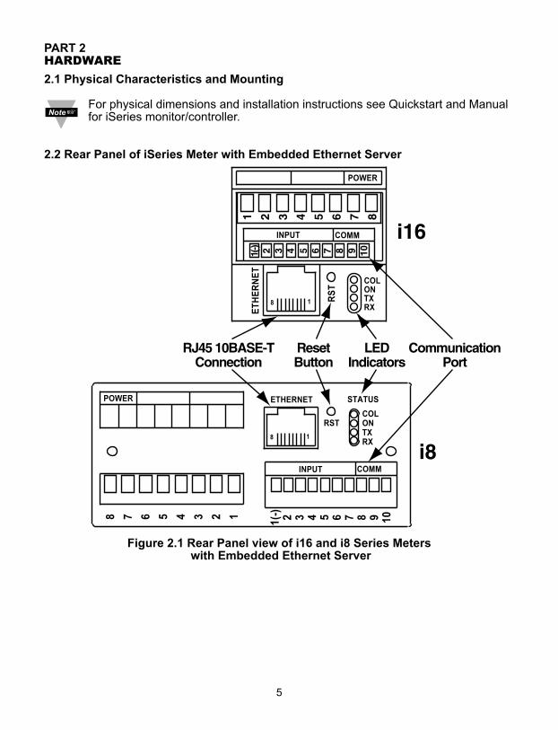
2.2 Rear Panel of iSeries Meter with Embedded Ethernet Server
Figure 2.1 Rear Panel view of i16 and i8 Series Meterswith Embedded Ethernet Server
5

Table 2.1 Rear Panel Annunciators
Serial Communication Interface Section (For Models with RS485):Pin 10 -Rx/-TxPin 9 +Rx/+TxPin 8 Return, Common Ground Shield Connection
Network Communication Interface Section:Ethernet RJ45 Female Connector for 10BASE-T connection
Reset Reset button used to change an IP Address and reset to the default password
RX LED (Green) Flashing: Indicates transmission from the Serial port ON: Indicates that the reset button is momentarily pushed
TX LED (Yellow) Flashing: Indicates reception to the Serial portON: Indicates that the reset button is momentarily pushed
ON LED (Green) ON: Indicates Power On. Flashing: Indicates connection to network host established
COL LED (Red) ON: Indicates that the Ethernet communication collapsed due to high network traffic
Both RX and TX stay ON when the reset button is pushed. They turn OFFafter a new IP address has been entered.
6

2.3 Serial Communication Interfaces (For Models with RS485 Port)
The iSeries controller/monitor with the Embedded Ethernet Server option board supportonly RS485/422 interfaces. These standards define the electrical characteristics of acommunication network. The RS485 port of the Ethernet Server is fully compatible foruse with RS422 instruments. The RS485 is an extended version of the RS422communication standard which increases the allowable number of devices from 10 to 32by improving the electrical characteristics.
• The RS485 standard (multi-point) allows one or more devices (multi-dropped) to be connected to the Ethernet Server using a two-wire connection (half-duplex) +Rx/+Tx and –Rx/-Tx. Use of RS485 communications allows up to 32 devices to connect to theWeb Server with cable length up to 4000 feet long.
Although the RS485 is commonly referred to as a "two wire" connection, the Web Server also provides a ground/return shield connection to use as a commonconnection for EMI noise protection.
Table 2.2 shows some characteristics of the RS485 communication interface.
Table 2.2Data Transmission Characteristics RS485Transmission Mode DifferentialElectrical connections 2 wireDrivers per line 32 driversReceivers per line 32 receiverMaximum data rate 10M bits/sMaximum cable length 4000 ft (1200 meters)
7

2.3.1 Wiring RS485 Interface
RS485 interface uses a two-wire communication system (one for transmitting and one forreceiving) plus a common wire to connect to the shield of the cable. It is recommendedto use a shielded cable with one twisted pair.
Use of twisted pair and shield will significantly improve noise immunity.
Figure 2.2 shows multi-point, half-duplex RS485 interface connections for the EthernetServer.
Figure 2.2 Multi-point, Half-Duplex RS485 Wiring
Value of the termination resistor is not critical and depends on the cableimpedance.
Table 2.3 shows RS485 half-duplex hookup between the Ethernet Server serial port anddevice with RS485 communication interface.
Table 2.3
iSeries DEVICE # WITH RS485Pin 9 +Tx/+Rx (+Transmit/+Receive) +Tx/+Rx (+Transmit/+Receive)Pin 10 -Tx/-Rx (-Transmit/-Receive) -Tx/-Rx (-Transmit/-Receive)Pin 8 RTN (Common GND) GND (Common GND)
8
DEVICE #1 DEVICE #29
DEVICE #31
DEVICE #30DEVICE #2
120 OhmTermination resistor
GND
-Tx/-Rx+Tx/+Rx+Tx/+Rx
-Tx/-Rx
Twisted shielded pair
-Tx/
-Rx
-Tx/
-Rx
-Tx/
-Rx
-Tx/
-Rx
+Tx/
+Rx
+Tx/
+Rx
GN
D
GN
DG
ND
GN
D
+Tx/
+Rx
+Tx/
+Rx
.........................
.........................
...............................
...............................
iSeries

2.4 Network Communication Interfaces
2.4.1 10Base-T RJ-45 pinout
The 10BASE-T Ethernet network (RJ-45) system is used in the Ethernet Server fornetwork connectivity. The 10 Mbps twisted-pair Ethernet system operates over two pairsof wires. One pair is used for receiving data signals and the other pair is used fortransmitting data signals. This means that four pins of the eight-pin connector are used.
Figure 2.3 RJ45 Pinout
2.4.2 10Base-T Crossover Wiring
When connecting the Ethernet Server directly to the computer, the transmit data pins ofthe computer should be wired to the receive data pins of the Ethernet Server, and viceversa. The 10Base-T crossover cable with pin connection assignments are shown onFigure 2.4.
Figure 2.4 10Base-T Crossover Cable Wiring
Use straight through cable for connecting the Ethernet Server to the Ethernetnetwork. Crossover will be done inside a hub.
9
Pin Name Description1 +Tx + Transmit Data2 -Tx - Transmit Data3 +RX + Receive Data4 N/C Not Connected5 N/C Not Connected6 -Rx - Receive Data7 N/C Not Connected8 N/C Not Connected

PART 3NETWORK CONFIGURATION
3.1 Network Protocols
The Ethernet Server can be connected to the network using standard TCP/IP protocols.It is also supported by ARP and HTTP protocols. TCP/IP networking protocols aresuperimposed into a local Ethernet network until, if so desired, a connection is made tothe Internet.
3.2 Ethernet (MAC) Address
MAC (Media Access Control) address is your computer's unique hardware number.When you're connected to the Internet from your computer, a correspondence tablerelates your IP address to your computer's physical (MAC) address on the LAN. TheMAC address can be found on the label of your device and contains 6 byte(12 characters) of hexadecimal numbers XX:XX:XX:XX:XX:XX hex
For example: 0A:0C:3D:0B:0A:0B
You need to know this number to access the Ethernet Server to change the IP address.
There is room on the label to put your IP address. See Figures 3.1 and 3.2.
Figure 3.1 i8 - Labeling
10
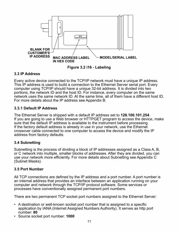
Figure 3.2 i16 - Labeling
3.3 IP Address
Every active device connected to the TCP/IP network must have a unique IP address.This IP address is used to build a connection to the Ethernet Server serial port. Everycomputer using TCP/IP should have a unique 32-bit address. It is divided into twoportions, the network ID and the host ID. For instance, every computer on the samenetwork uses the same network ID. At the same time, all of them have a different host ID.For more details about the IP address see Appendix B.
3.3.1 Default IP Address
The Ethernet Server is shipped with a default IP address set to 128.100.101.254. If you are going to use a Web browser or HTTPGET program to access the device, makesure that the default IP address is available to the instrument before processing.If the factory default address is already in use in your network, use the Ethernetcrossover cable connected to one computer to access the device and modify the IPaddress from factory defaults.
3.4 Subnetting
Subnetting is the process of dividing a block of IP addresses assigned as a Class A, B,or C network into multiple, smaller blocks of addresses. After they are divided, you canuse your network more efficiently. For more details about Subnetting see Appendix C(Subnet Masks).
3.5 Port Number
All TCP connections are defined by the IP address and a port number. A port number isan internal address that provides an interface between an application running on yourcomputer and network through the TCP/IP protocol software. Some services orprocesses have conventionally assigned permanent port numbers.
There are two permanent TCP socket port numbers assigned to the Ethernet Server:
• A destination or well-known socket port number that is assigned to a specific application by IANA (Internet Assigned Numbers Authority). It serves as http port number: 80
• Source socket port number: 100011

PART 4SERIAL INTERFACE CONFIGURATION
An industrial device with serial interfaces (PLC, CNC controllers, PC, Data DisplayDevices, etc.) can be connected to the serial port of the Web Server.
4.1 Communication Protocol
A data communication protocol defines the rules and structure of messages used by alldevices on a network for data exchange. A typical transaction will consist of a request tosend from the MASTER followed by the response from one or more SLAVE devices.Either a single (point-to-point) or multi-drop network (multi-point) is possible.
4.2 Command Structure
There are different command types associated with communication between theEthernet Server and your device shown in Table 4.1, which shows the Command PrefixLetters (Command Classes)
Table 4.1 Command Prefix Letters
COMMAND PREFIX (COMMAND CLASS) MEANING
^AE Special read, Communication parameters P (Put) Write HEX data into RAMW (Write) Write HEX data into EEPROM. G (Get) Read HEX data from RAMR (Read) Read HEX data from EEPROMU Read status byteV Read measurement data string in decimal formatX Read measurement data values in decimal formatD DisableE EnableZ Reset
4.3 Command Formats
Table 4.2 shows the command formats for the Ethernet Server.
Table 4.2 Command Formats
For "P" and "W" Command For "G" and "R" Command For "X", "V", "U", "D", "E",classes: classes: & "Z" Command classes:Point-to-point mode Point-to-point mode Point-to-point mode* ccc<data><cr> * ccc <cr> * ccc <cr>Multi-point mode Multi-point mode Multi-point mode* nnccc [<data>]<cr> * nnccc <cr> * nnccc <cr>
12
Where:"*" is the selected Recognition Character. You may select any ASCII table symbol from"!" (HEX address "21") to the right-hand brace (HEX "7D") except for the caret "^", "A","E", which are reserved for bus format request.
"ccc" stands for the hex-ASCII Command Class letter (one of eleven given in Table 4.1),followed by the two hex-ASCII Command Suffix characters identifying the meter data,features, or menu items to which the command is directed.
"<data>" is the string of characters containing the variable information the computer issending to the meter. These data (whether BCD or binary) are encoded into hex-ASCIIcharacter (see Appendix D for binary-hex-ASCII chart), two characters to the byte.Square brackets [indicating optional status] enclose this string, since some commandscontain no data.
"<nn>" are the two ASCII characters for the device Bus Address of RS485 communication.Use values from "00" to hex "C7" (199 decimal).
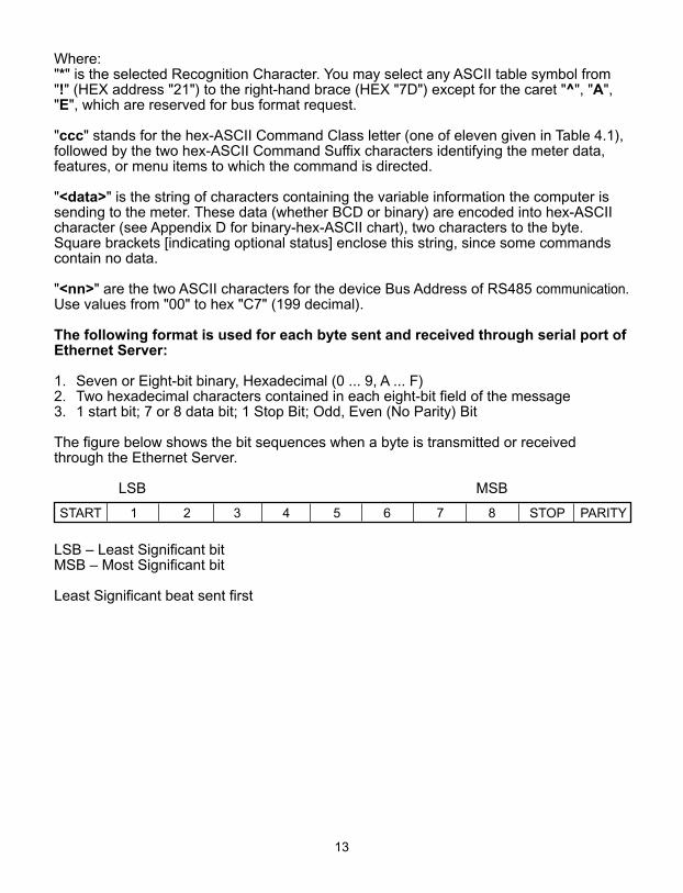
The following format is used for each byte sent and received through serial port ofEthernet Server:
1. Seven or Eight-bit binary, Hexadecimal (0 ... 9, A ... F) 2. Two hexadecimal characters contained in each eight-bit field of the message 3. 1 start bit; 7 or 8 data bit; 1 Stop Bit; Odd, Even (No Parity) Bit
The figure below shows the bit sequences when a byte is transmitted or receivedthrough the Ethernet Server.
LSB MSB
LSB – Least Significant bitMSB – Most Significant bit
Least Significant beat sent first
13
START 1 2 3 4 5 6 7 8 STOP PARITY

PART 5OPERATIONS
5.1 Modifying the IP Address
The IP Address may be set via the network by using "Setip" DOS program.
The setip.exe file is used to set a new IP Address. This file will be automatically installedwhen you run any Ethernet Server related software available on our website and CD.
Example to use the "setip" program:
1. Choose a qualified new IP address. 2. Make sure that the new IP address is available to the device before processing
by pinging the new IP address:
"Ping.exe" file should be installed and available on each computer configured touse TCP/IP.
C:\ping 128.100.101.33
If you get the following response, it means that this IP address is not taken:
Pinging 128.100.101.33 with 32 bytes of data.
Request timed out:Request timed out:Request timed out:Request timed out:
3. Create a directory C:\WebServer\Setip4. Copy setip.exe file to this directory.
Push the "Reset" button on the Ethernet Server before proceeding to the nextstep.
5. Make sure that you are on this directory and then enter "setip", followed by the MACaddress and the new IP address:
C:\WebServer\Setip\setip XX:XX:XX:XX:XX:XX DDD.DDD.DDD.DDDor
C:\WebServer\Setip\setip ddd.ddd.ddd.ddd.ddd.ddd DDD.DDD.DDD.DDD
where: XX:XX:XX:XX:XX:XX is a MAC address in hexadecimalddd.ddd.ddd.ddd.ddd.ddd is a MAC address in decimalDDD.DDD.DDD.DDD is a new IP address in decimal
14

For example:
C:\WebServer\Setip\setip 0A:0C:3D:0B:0A:0B 128.100.101.33 for MAC address in Hexadecimal
C:\WebServer\Setip\setip 10.12.61.11.10.11 128.100.101.33 for MAC address in decimal
6. Make sure that the Ethernet Server has a new IP address by pinging the new IPaddress
C:\ping 128.100.101.33
If you got the following respond, it means that your device now has the new IP address:
Pinging 128.100.101.33 with 32 bytes of data.
Reply from 128.100.101.33: bytes = 32 time = 4 ms TTL = 32Reply from 128.100.101.33: bytes = 32 time = 4 ms TTL = 32 Reply from 128.100.101.33: bytes = 32 time = 4 ms TTL = 32 Reply from 128.100.101.33: bytes = 32 time = 4 ms TTL = 32
15
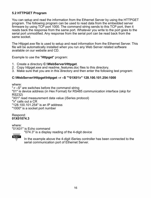
5.2 HTTPGET Program
You can setup and read the information from the Ethernet Server by using the HTTPGETprogram. The following program can be used to read data from the embedded serverfirmware by using TCP port 1000. The command string sends to this TCP port, then itreads back the response from the same port. Whatever you write to the port goes to theserial port unmodified. Any response from the serial port can be read back from thesame socket.
The Httpget.exe file is used to setup and read information from the Ethernet Server. Thisfile will be automatically installed when you run any Web Server related softwareavailable on our website and CD.
Example to use the "Httpget" program:
1. Create a directory C:\WebServer\Httpget.2. Copy httpget.exe and readme_features.doc files to this directory.3. Make sure that you are in this directory and then enter the following test program:
C:\WebServer\Httpget\httpget –r –S "*01X01\r" 128.100.101.254:1000
where:"-r –S" are switches before the command string"01" is device address (in Hex Format) for RS485 communication interface (skip forRS232)"X01" read measurement data value (iSeries protocol)"\r" calls out a CR"128.100.101.254" is an IP address "1000" is a socket port number
Respond: 01X01074.3
where:"01X01" is Echo command
"074.3" is a display reading of the 4-digit device
In the example above the 4-digit iSeries controller has been connected to theserial communication port of Ethernet Server.
16
5.3 ARP Protocol
ARP is the Internet layer protocol responsible for determining the MAC (hardware)address that corresponds to a particular IP address. The ARP command allows the userto view the current contents of the ARP cache of the local computer (residing on thesame network) or remote computer (residing on the different network) through a router.Microsoft includes the ARP.EXE utility for viewing and modifying the ARP cache with itsWindows product. The following ARP commands can be used to view cache entries:
• arp –a � Use this command to view all ARP cache entries.• arp –a plus IP address � Use this command to view ARP cache entries associated
with one particular interface on a network with multiple adapters.• arp –g � Same as arp –a.• arp –N � Use this command to display ARP entries for specific network interface.• arp – s plus IP address plus Physical address � Use this command to manually add
a permanent static entry to the ARP cache.• arp –d � Use this command to manually delete a static entry.
Ping the destination computer using IP address first before using the arp -acommand.
17

Figure 5.1 below shows examples of arp commands and responses.You computer has an IP address 128.100.101.118. The destination computer has an IP address 128.100.101.96
Figure 5.1 arp –a Commands and Responses
18
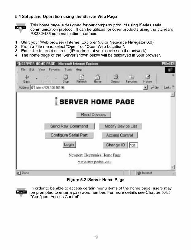
5.4 Setup and Operation using the iServer Web Page
This home page is designed for our company product using iSeries serialcommunication protocol. It can be utilized for other products using the standardRS232/485 communication interface.
1. Start your Web browser (Internet Explorer 5.0 or Netscape Navigator 6.0).2. From a File menu select "Open" or "Open Web Location".3. Enter the Internet address (IP address of your device on the network)4. The home page of the iServer shown below will be displayed in your browser.
Figure 5.2 iServer Home Page
In order to be able to access certain menu items of the home page, users maybe prompted to enter a password number. For more details see Chapter 5.4.5"Configure Access Control".
19

This home page provides the following features:
5.4.1 Read Devices:• Read variables from up to four different devices.
• Read up to four variables from the same device. • Manually or automatically update readings from your devices. Set time interval for
Auto Update.
• Read and write the setpoint values to the device.
20

If access to the menu item is restricted (untrusted host), the user will beprompted for a password number.In order to proceed to the "Device Setpoints" submenu, the user should enterthe correct password for access level "1" (operator level) or access level "0" (administrator level).
5.4.2 Send Raw Command•Send single command and receive response.
5.4.3 Modify Device List Entry•Modify device list or parameters.
Device Address or ID is in Hex Format. See Appendix D for conversion.
21

• Up to four different devices or parameters can be modified.
5.4.4 Serial Port Configuration
• Allows the user to adjust serial communications settings of the instrument.• When connecting your instrument to the iServer, the communications parameters
must match.
22

5.4.5 Configure Access Control
• Allows the network administrator to set a different access level to the iServer parameters for the different groups or individual users.
There are three different access levels:
1. Access Level "0" (administrator level) allows certain groups and individual users to access and modify "All" iServer menu items without any restrictions (Trusted Host).
2. Access Level "1" (operator level) allows certain groups and individual users to access and modify "Read Devices" and "Device Setpoints" menus only (Untrusted Host).
3. Access Level "2" (read-only level) allow certain groups and individual users to access "Read Devices" menu only (Untrusted Host)
The network administrator can change the access level by properly masking certain IPaddresses. See Appendix C for more details about the IP Netmask.
23

5.4.6 Log In
• Allows the user to access the menu items of the iServer Home page according to their access level. Except for "Read Device", if user attempts to advance to the menu items,they will be prompted to enter the password only once to open the menu items.
5.4.7 Change ID
• Allows the user to access devices with different addresses residing on RS485 communication interface.
ID number relates to the Device or Variable No. Refer to Device Setup Section5.4.3.ID number is blank for RS232 communication interface.
24

25
5.5 Mail Notifier Software
For complete information of how to use the Mail Notifier software, click on theHelp menu of the main window.
The Mail Notifier software utilizes E-Mail notifications of alarm conditions of the deviceshaving either embedded iServer board or connected via the stand alone iServer units,which reformats RS232/485 bus traffic into Ethernet packets. Hence users/operators canbe notified automatically of alarm conditions monitored via internet connectionsthroughout the world. By use of the E-Mail forwarding of alarm conditions, alarmconditions can be monitored on a network isolated from the internet and forwarded toconnections on the Internet.
The Mail Notifier utility operates under Windows 95,98, NT 4.0, and NT 2000 inconjunction with existing E-Mail that supports the MAPI messaging interface. If MSOutlook has been loaded, the MAPI support should be available.
5.5.1 Installation
The Mail Notifier must be loaded on a computer running Microsoft Windows (versionsspecified earlier) and with a MAPI client software. Network access must be availablebetween this computer and the iServer. Network access must also be available from thiscomputer to the appropriate E-Mail server and from the E-Mail server to the recipient’sE-Mail server.
Figure 5.3 iServer Mail Notifier Main Window

5.5.2 Program Options Setup and Configuration
Complete program setup requires: • Entering a recipient for the E-Mail• Specifying connection details to MAPI services.• Defining alarms for devices, and selecting how and when the E-Mail will be active.
Figure 5.4 iServer Mail Notifier Profile Setup
The E-Mail User tab provides fields to define the name/profile for the Mail Notifier toutilize when E-Mail is sent.
Follow the steps below to set profile in Microsoft Exchange (5.0.1458.47)1. Start Microsoft Exchange. 2. From Menu bar select tools, options. 3. It will open to the General tab. 4. On the General tab there is the "When starting Microsoft Exchange" options. 5. The profile name is specified under the "Always use this profile" option button. 6. On the Mail Notifier, go to View, Options. 7. From the options dialog, go to the E-mail User tab. 8. Set the Name/Profile to the profile name obtained in step 5 9. Make sure that the E-Mail Access option is set to MS Outlook. (This is used to prevent
input of a password -- which isn’t going to be used with Microsoft Exchange)
The Send To tab contains a field to specify an E-mail address to which alarm notificationswill be sent. Only one entry is permitted, but with some E-Mail packages, the entry canrepresent a group of users with different E-Mail addresses.
26
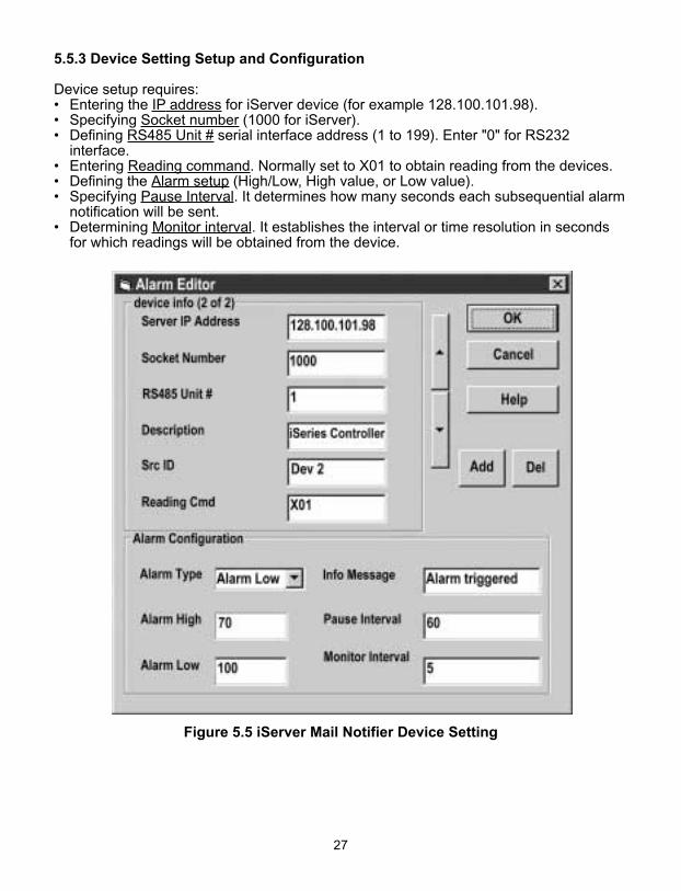
5.5.3 Device Setting Setup and Configuration
Device setup requires:• Entering the IP address for iServer device (for example 128.100.101.98).• Specifying Socket number (1000 for iServer).• Defining RS485 Unit # serial interface address (1 to 199). Enter "0" for RS232
interface.• Entering Reading command. Normally set to X01 to obtain reading from the devices.• Defining the Alarm setup (High/Low, High value, or Low value).• Specifying Pause Interval. It determines how many seconds each subsequential alarm
notification will be sent.• Determining Monitor interval. It establishes the interval or time resolution in seconds
for which readings will be obtained from the device.
Figure 5.5 iServer Mail Notifier Device Setting
27

PART 6SPECIFICATIONS
Standards Compliance
IEEE 802.3 10Base-T
Supported Protocols
TCP/IP, ARP, HTTPGET
Serial Interface (if applicable)
Communication Standard: RS485, RS422
Transfer speed (Baud rate): 2400, 4800,9600, 19200, 38400, 57600, 115200 bps
Bad Parity: dropped, accepted, marked
Parity bit: odd, even, none
Data bit: 7, 8 bit
Stop bit: 1 bit
Start bit: 1 bit
Multi-point Address (RS485): 0 to 199
Flow Control: No Flow control
Screw terminals for RS232/485/422interface
Network Interface
10Base-T port (RJ45 connector)
Socket Port number: 1000
HTTP Port number: 80
Power
10 to 32 Vdc
Power Consumption
2 W
28
Environmental Conditions
0 to 50°C (32 to 122°F), 90% RH
Refer to the iSeries Manual andQuickstart for physicalcharacteristics of iSeries deviceswith the Embedded EthernetServer.
Approvals
UL, CUL and see CE Approval Section

PART 7FACTORY PRESET VALUES
PRESET PARAMETERS FACTORY DEFAULTS NOTESNetwork Interface:IP address 128.100.101.254Serial Interface:Communication Standard RS485Transfer Speed 9600 bpsBad Parity acceptedParity oddTimeout 750 msec
29

30
CE APPROVAL INFORMATION1. Electrical Compatibility (EMC)
This device comforms with requirements of EMC Directive 89/336/EEC,amended by 93/68/EEC. This instrument complies with the following EMC Immunity Standards as tested per EN 50082-2, 1995 (Industrial environment)
Phenomena Test Specification Basic Standard
Electrostatic +/- 4 kV contact discharge IEC 1000-4-2Discharge +/- 8 kV air discharge Performance
Criteria B
Radio Frequency 27 - 1000 MHz IEC 1000-4-3electromagnetic 10 V/m Performancefield. 80% AM (1 KHz) Criteria A
Radio Frequency 900 MHz IEC 1000-4-3electromagnetic field. 10 V/m PerformancePulse modulated. 50% Duty cycle @ 200 Hz Criteria A
Fast Transients +/- 2 kV (ac mains) IEC 1000-4-4+/- 1 kV (dc, signal I/O) Performance5/50 ns Tr/Th, 5 KHz rep. freq. Criteria B
Radio Frequency 0.15 - 80 MHz IEC 1000-4-6conducted 10 V/m Performance
80% AM (1 KHz) Criteria A
This instrument complies with the following EMC Emission Standards astested per EN 50081-1, 1992 (Residential, Commercial and Light Industrial)
Phenomena Frequency Limits BasicRange Standard
Radiated 30-230 MHz 30 dB_V/m at 10 m CISPR 22Emission 230-1000 MHz 37 dB_V/m at 10 m Class B
quasi peak
Conducted 0.15-0.5 MHz 66-56 dB_V quasi peak CISPR 22Emission 0.5-5 MHz 56 dB_V quasi peak Class B
5-30 MHz 60 dB_V quasi peak
2. SafetyThis device conforms with Low Voltage Directive 73/23/EEC, amended by 93/68/EEC. The following LVD requirements have been met to comply withEN 61010-1, 1993 (Electrical equipment for measurement, control and laboratory use)
1. Pollution Degree 22. Installation Category II3. Double Insulation4. Class II Equipment (90-240 Vac Powered Units)
Class III Equipment (12-36 Vdc Low Power Option)
FCCThis device complies with Part 15, Subpart B, Class B of the FCC rules

APPENDIX A GLOSSARY
User of this manual should be familiar with following definitions:
ARP (Address Resolution Protocol) is a protocol for mapping an Internet Protocol address (IP address) to a physical machine address that is recognized in the localnetwork. For example, the IP address in use today is an address that is 32-bits long. In an Ethernet local area network, however, addresses for attached devices are 48-bitslong. (The physical machine address is also known as a Media Access Control or MAC address.) A table, usually called the ARP cache, is used to maintain a correlationbetween each MAC address and its corresponding IP address. ARP provides theprotocol rules for making this correlation and providing address conversion in bothdirections.
Ethernet is a network protocol defined by the IEEE 802.3 standard. Ethernet-based networks use MAC Address rather then IP Address to exchange data betweencomputers. By using ARP and adding TCP/IP support, Ethernet devices may beconnected as part of the Internet. An Ethernet LAN typically uses coaxial cable or specialgrades of twisted pair wires. The most commonly installed Ethernet systems are called10BASE-T and provide transmission speeds up to 10 Mbps. Devices are connected tothe cable and compete for access using a Carrier Sense Multiple Access with CollisionDetection (CSMA/CD) protocol.
IP (Internet Protocol) is the method or protocol by which data is sent from one computerto another on the Internet.
IP address (Internet Protocol address) is a 32-bit number that identifies each senderor receiver of information that is sent in packets across the Internet.
IP Netmask is a 32-bit pattern of bits used to determine which part of the IP address isthe network portion and which part is the host portion.
MAC (Media Access Control) Address is your computer's unique hardware number.When you're connected to the Internet from your computer, a correspondence tablerelates your IP address to your computer's physical (MAC) address on the LAN.
Ping is a utility that tests the network connectivity. It is used to determine if the host iscapable of exchanging information with another host.
Port number/Socket number is a way to identify a specific process to which an Internetor other network message is to be forwarded when it arrives at a server. It is apredefined address that serves as a route from the application to the Transport layer orfrom the Transport layer to the application of the TCP/IP system.
Sockets are a method for communication between a client program and a serverprogram in a network and defined as "the endpoint in a connection." Informationtransferred across the Internet primarily occurs between sockets.
TCP/IP (Transmission Control Protocol/Internet Protocol) is the basic communicationlanguage or protocol of the Internet. When you are set up with direct access to theInternet, your computer is provided with a copy of the TCP/IP program just as everyother computer that you may send messages to or get information from also has a copyof TCP/IP. TCP/IP often is used as a general term to indicate generic access to theInternet.
31

Appendix B IP Address
An IP address is a unique 32-bit address assigned to a computer and includes:
• A network ID number identifying a network.• A host ID number identifying a computer on the network.
All IP addresses have been divided into three smaller groups (classes) A, B and C
• Class A addresses have 8-bits of network ID and 24-bits of host ID. They can support a large number of hosts, approximately 2 = 16,777,216 computers per network.
The IP addresses range in binary from 00000001.xxxxxxxx.xxxxxxxx.xxxxxxxxto 01111111.xxxxxxxx.xxxxxxxx.xxxxxxxx
The IP addresses range in decimal from 1.x.x.x to 127.x.x.x
Class A network ID’s support a very large number of hosts.
• Class B addresses have 16-bits of network ID and 16-bits of host ID. They can support approximately 216 = 65,536 computers per network.
The IP addresses range in binary from 10000000 00000000.xxxxxxxx.xxxxxxxxto 10111111 11111111.xxxxxxxx.xxxxxxxx
The IP addresses range in decimal from 128.0.x.x TO 191.255.xxx.xxx
Class B network ID’s support a medium number of hosts.
• Class C addresses have 24-bits of network ID and 8-bits of host ID. They can support approximately 28 = 256 computers per network.
The IP addresses range in binary from 11000000.00000000.00000000.xxxxxxxx to 11011111.11111111.11111111.xxxxxxxx
The IP addresses range in decimal from 192.0.0.xxx to 223.255.255.xxx
Class C network ID’s support a small number of hosts.
The rest of the addresses are divided into two classes, D and E.Class D networks are not assigned to the host. They are used for multicasting. The address range from 224.x.x.x to 239.x.x.x
Class E networks are experimental or reserved addresses.The address range from 240.x.x.x to 247.x.x.x
32

Appendix C IP Netmask
IP Netmask or Subnet Mask is a 32-bit pattern of ones and zeros used to determinenetwork portion of an IP address from the host portion of the IP address. Subnet mask isa network ID that is created by borrowing bits from host portion of IP address and usingthem as part of a network ID. The table below shows a default subnet mask for addressClasses A, B, and C. Each bit that is set to "1" in the subnet mask corresponds to the bitin the IP address that is to be used as the network ID. Each bit that is set to "0" in thesubnet mask corresponds to a bit in the IP address that is to be used as the host ID.
Address Class Mask Binary Value Mask Decimal Valueor Dotted Notation
Class A 255.0.0.0Class B 255.255.0.0Class C 255.255.255.0
If your network requires more network ID’s, you can extend the default subnet mask toinclude additional bits from the host ID. This allows for additional network ID’s within thenetwork. The table below shows some examples of subnet masks and bits moved fromthe hosts ID to create a new subnet.
Mask Dotted Notation Mask Binary Mask BitsClass A
255.0.0.0 (Default) 0255.192.0.0 2255.224.0.0 3255.240.0.0 4255.248.0.0 5255.252.0.0 6255.254.0.0 7255.255.0.0 8255.255.128.0 9255.255.192.0.0 10……………......... .255.255.255.252 22
Class B255.255.0.0 (Default) 0255.255.192.0 2……………......... .255.255.255.252 14
Class C255.255.255.0 (Default) 0255.255.255.192 2…………………. .255.255.255.254 6
To determine the number of valid hosts ID’s remaining after subnetting, use the followingequation: 2n – 2, where n is the number of octet digits left after the subnet mask.
33
11111111111111111111111111111111111111111111111111111111111111111111111111111111. . . . . . . .11111111
00000000110000001110000011110000111110001111110011111110111111111111111111111111. . . . . . . .11111111
00000000000000000000000000000000000000000000000000000000000000001000000011000000. . . . . . . .11111111
00000000000000000000000000000000000000000000000000000000000000000000000000000000. . . . . . . .11111100
1111111111111111. . . . . . . .11111111
1111111111111111. . . . . . . .11111111
0000000011000000. . . . . . . .11111111
0000000000000000. . . . . . . .11111100
1111111111111111. . . . . . . .11111111
1111111111111111. . . . . . . .11111111
1111111111111111. . . . . . . .11111111
0000000011000000. . . . . . . .11111100
111111111111111111111111
000000001111111111111111
000000000000000011111111
000000000000000000000000

Appendix D ASCII Chart
ASCII Dec Hex Binary ASCII Dec Hex BinaryChar No Parity Char No parityNUL 00 00 00000000 @ 64 40 01000000SOH 01 01 00000001 A 65 41 01000000STX 02 02 00000010 B 66 42 01000010ETX 03 03 00000011 C 67 43 01000011EOT 04 04 00000100 D 68 44 01000100ENQ 05 05 00000101 E 69 45 01000101ACK 06 06 00000110 F 70 46 01000110BEL 07 07 00000111 G 71 47 01000111BS 08 08 00001000 H 72 48 01001000HT 09 09 00001001 I 73 49 01001001LF 10 0A 00001010 J 74 4A 01001010VT 11 0B 00001011 K 75 4B 01001011FF 12 0C 00001100 L 76 4C 01001100CR 13 0D 00001101 M 77 4D 01001101SO 14 0E 00001110 N 78 4E 01001110SI 15 0F 00001111 O 79 4F 01001111
DLE 16 10 00010000 P 80 50 01010000DC1 17 11 00010001 Q 81 51 01010001DC2 18 12 00010010 R 82 52 01010010DC3 19 13 00010011 S 83 53 01010011DC4 20 14 00010100 T 84 54 01010100NAK 21 15 00010101 U 85 55 01010101SYN 22 16 00010110 V 86 56 01010110ETB 23 17 00010111 W 87 57 01010111CAN 24 18 00011000 X 88 58 01011000EM 25 19 00011001 Y 89 59 01011001
SUB 26 1A 00011010 Z 90 5A 01011010ESC 27 1B 00011011 [ 91 5B 01011011FS 28 1C 00011100 \ 92 5C 01011100GS 29 1D 00011101 ] 93 5D 01011101RS 30 1E 00011110 ^ 94 5E 01011110US 31 1F 00011111 _ 95 5F 01011111SP 32 20 00100000 ` 96 60 01100000! 33 21 00100001 a 97 61 01100001" 34 22 00100010 b 98 62 01100010# 35 23 00100011 c 99 63 01100011$ 36 24 00100100 d 100 64 01100100% 37 25 00100101 e 101 65 01100101& 38 26 00100110 f 102 66 01100110‘ 39 27 00100111 g 103 67 01100111( 40 28 00101000 h 104 68 01101000) 41 29 00101001 I 105 69 01101001* 42 2A 00101010 j 106 6A 01101010+ 43 2B 00101011 k 107 6B 01101011, 44 2C 00101100 l 108 6C 01101100- 45 2D 00101101 m 109 6D 01101101. 46 2E 00101110 n 110 6E 01101110
34

Appendix D ASCII Chart Continuation/ 47 2F 00101111 o 111 6F 011011110 48 30 00110000 p 112 70 011100001 49 31 00110001 q 113 71 011100012 50 32 00110010 r 114 72 011100103 51 33 00110011 s 115 73 011100114 52 34 00110100 t 116 74 011101005 53 35 00110101 u 117 75 011101016 54 36 00110110 v 118 76 011101107 55 37 00110111 w 119 77 011101118 56 38 00111000 x 120 78 011110009 57 39 00111001 y 121 79 01111001: 58 3A 00111010 z 122 7A 01111010; 59 3B 00111011 { 123 7B 01111011< 60 3C 00111100 | 124 7C 01111100= 61 3D 00111101 } 125 7D 01111101> 62 3E 00111110 ~ 126 7E 01111110? 63 3F 00111111 DEL 127 7F 01111111
ASCII Control CodesASCII Dec Hex Ctrl Key Definition ASCII Dec Hex Ctrl Key DefinitionChar Equiv. Char Equiv.NUL 00 00 Crtl @ Null Character DC1 17 11 Crtl Q Data Control 1
- XONSOH 01 01 Crtl A Start of DC2 18 12 Crtl R Data Control 2
HeaderSTX 02 02 Crtl B Start of Text DC3 19 13 Crtl S Data Control 3
- XOFFETX 03 03 Crtl C End of Text DC4 20 14 Crtl T Data Control 4EOT 04 04 Crtl D End of NAK 21 15 Crtl U Negative
Transmission AcknowledgeENQ 05 05 Crtl E Inquiry SYN 22 16 Crtl V Synchronous
IdleACK 06 06 Crtl F Acknowledge ETB 23 17 Crtl W End of Trans
BlockBEL 07 07 Crtl G Bell CAN 24 18 Crtl X CancelBS 08 08 Crtl H Back Space EM 25 19 Crtl Y End of MediumHT 09 09 Crtl I Horizontal SUB 26 1A Crtl Z Substitute
TabulationLF 10 0A Crtl J Line Feed ESC 27 1B Crtl [ EscapeVT 11 0B Crtl K Vertical FS 28 1C Crtl \ File Separator
TabulationFF 12 0C Crtl L Form Feed GS 29 1D Crtl ] Group
SeparatorCR 13 0D Crtl M Carriage RS 30 1E Crtl | Record
Return SeparatorSO 14 0E Crtl N Shift Out US 31 1F Crtl _ Unit SeparatorSI 15 0F Crtl O Shift In SP 32 20 Space
DLE 16 10 Crtl P Data LinkEscape
35

NOTES
36

NOTES
37

NOTES
38

Warranty/DisclaimerNEWPORT Electronics, Inc. warrants this unit to be free of defects in materials and workmanship for a period of one(1) year from the date of purchase. In addition to NEWPORT’s standard warranty period, NEWPORT Electronics willextend the warranty period for four (4) additional years if the warranty card enclosed with each instrument isreturned to NEWPORT.
If the unit should malfunction, it must be returned to the factory for evaluation. NEWPORT’s Customer ServiceDepartment will issue an Authorized Return (AR) number immediately upon phone or written request. Uponexamination by NEWPORT, if the unit is found to be defective it will be repaired or replaced at no charge.NEWPORT’s WARRANTY does not apply to defects resulting from any action of the purchaser, including but notlimited to mishandling, improper interfacing, operation outside of design limits, improper repair, or unauthorizedmodification. This WARRANTY is VOID if the unit shows evidence of having been tampered with or shows evidenceof being damaged as a result of excessive corrosion; or current, heat, moisture or vibration; improper specification;misapplication; misuse or other operating conditions outside of NEWPORT’s control. Components which wear are notwarranted, including but not limited to contact points, fuses, and triacs.
NEWPORT is pleased to offer suggestions on the use of its various products. However, NEWPORT neitherassumes responsibility for any omissions or errors nor assumes liability for any damages that result fromthe use of its products in accordance with information provided by NEWPORT, either verbal or written.NEWPORT warrants only that the parts manufactured by it will be as specified and free of defects.NEWPORT MAKES NO OTHER WARRANTIES OR REPRESENTATIONS OF ANY KIND WHATSOEVER,EXPRESSED OR IMPLIED, EXCEPT THAT OF TITLE, AND ALL IMPLIED WARRANTIES INCLUDING ANYWARRANTY OF MERCHANTABILITY AND FITNESS FOR A PARTICULAR PURPOSE ARE HEREBYDISCLAIMED. LIMITATION OF LIABILITY: The remedies of purchaser set forth herein are exclusive and thetotal liability of NEWPORT with respect to this order, whether based on contract, warranty, negligence,indemnification, strict liability or otherwise, shall not exceed the purchase price of the component uponwhich liability is based. In no event shall NEWPORT be liable for consequential, incidental or specialdamages.
CONDITIONS: Equipment sold by NEWPORT is not intended to be used, nor shall it be used: (1) as a “BasicComponent” under 10 CFR 21 (NRC), used in or with any nuclear installation or activity; or (2) in medical applicationsor used on humans. Should any Product(s) be used in or with any nuclear installation or activity, medical application,or used on humans, or misused in any way, NEWPORT assumes no responsibility as set forth in our basicWARRANTY / DISCLAIMER language, and additionally purchaser will indemnify NEWPORT and hold NEWPORTharmless from any liability or damage whatsoever arising out of the use of the Product(s) in such a manner.
Direct all warranty and repair requests/inquiries to the NEWPORT Customer Service Department.BEFORE RETURNING ANY PRODUCT(S) TO NEWPORT, PURCHASER MUST OBTAIN ANAUTHORIZED RETURN (AR) NUMBER FROM NEWPORT’S CUSTOMER SERVICE DEPARTMENT (INORDER TO AVOID PROCESSING DELAYS). The assigned AR number should then be marked on theoutside of the return package and on any correspondence.
The purchaser is responsible for shipping charges, freight, insurance and proper packaging to preventbreakage in transit.
FOR WARRANTY RETURNS, please have thefollowing information available BEFORE contacting NEWPORT:
1. P.O. number under which the product wasPURCHASED,
2. Model and serial number of the productunder warranty, and
3. Repair instructions and/or specificproblems relative to the product.
FOR NON-WARRANTY REPAIRS, consultNEWPORT for current repair charges. Have thefollowing information available BEFORE contactingNEWPORT:
1. P.O. number to cover the COST of the repair,
2. Model and serial number of product, and3. Repair instructions and/or specific problems
relative to the product.
NEWPORT’s policy is to make running changes, not model changes, whenever an improvement is possible.This affords our customers the latest in technology and engineering.NEWPORT is a registered trademark of NEWPORT Electronics, Inc.© Copyright 2001 NEWPORT Electronics, Inc. All rights reserved. This document may not be copied,photocopied, reproduced, translated, or reduced to any electronic medium or machine-readable form, inwhole or in part, without prior written consent of NEWPORT Electronics, Inc.
Return Requests/Inquiries

M3629/N/0702
For immediate technical or application assistance please call:
Newport Electronics, Inc.2229 South Yale Street • Santa Ana, CA • 92704 • U.S.A.
TEL: (714) 540-4914 • FAX: (714) 546-3022Toll Free: 1-800-639-7678 • http://www.newportUS.com • e-mail:[email protected]
ISO 9001 Certified
Newport Technologies, Inc.976 Bergar • Laval (Quebec) • H7L 5A1 • Canada
TEL: (514) 335-3183 • FAX: (514) 856-6886Toll Free: 1-800-639-7678 • http://www.newport.ca • e-mail:[email protected]
Newport Electronics, Ltd.One Omega Drive • River Bend Technology Centre
Northbank, Irlam • Manchester M44 5BD • United KingdomTel: +44 161 777 6611 • FAX: +44 161 777 6622
Toll Free: 0800 488 488 • http://www.newportuk.co.uk • e-mail:[email protected]
Newport Electronics B.V.Postbus 8034 • 1180 LA Amstelveen • The Netherlands
TEL: +31 20 3472121 • FAX: +31 20 6434643Toll Free: 0800 0993344 • http://www.newport.nl • e-mail: [email protected]
Newport Electronics spol s.r.o.Rudé armády 1868, 733 01 Karviná 8 • Czech Republic
TEL: +420 69 6311899 • FAX: +420 69 6311114Toll Free: 0800-1-66342 • http://www.newport.cz • e-mail: [email protected]
Newport Electronics GmbHDaimlerstrasse 26 • D-75392 Deckenpfronn • Germany
TEL: 49 7056 9398-0 • FAX: 49 7056 9398-29Toll Free: 0800 / 6397678 • http://www.newport.de • e-mail: [email protected]
Newport Electronique S.A.R.L.11, rue Jacques Cartier • 78280 Guyancourt • France
TEL: +33 1 61 37 29 00 • FAX: +33 1 30 57 54 27Toll Free: 0800 466 342 • http://www.newport.fr • e-mail: [email protected]
Mexico and Latin AmericaTEL: 001-800-826-6342 • FAX: 001 (203) 359-7807
En Español: 001 (203) 359-7803
®