ISA100 Wireless Applications, Technology, and Systems
31
This document is Business Confidential to Members of the ISA100 Wireless Compliance Institute. Do not share with other parties. ISA100 Wireless Applications, Technology, and Systems A Tutorial White Paper Version 10 November 2014 Copyright © 2014 ASCI - Automation Standards Compliance Institute. All rights reserved.
Transcript of ISA100 Wireless Applications, Technology, and Systems
This document is Business Confidential to Members of the ISA100 Wireless Compliance Institute. Do not share with other parties.
ISA100 Wireless Applications, Technology, and Systems
A Tutorial White Paper
Version 10 November 2014
Copyright © 2014 ASCI - Automation Standards Compliance Institute. All rights reserved.

– 2 – ISA100 Wireless Tutorial
ABSTRACT
Industrial wireless instrumentation is widely considered suitable for monitoring, control , and alarms, including safety alarms. Systems may be deployed using an ad hoc methodology to get started, but users are better served when systems are scaled using a more structured methodology that leverages the “Internet of Things .” User acceptance of and demand for IP-based scaled mission-critical wireless technology is driving adoption of ISA100 Wireless. ISA100 Wireless is poised to support a fast growth curve with its open design, scalable system and product architectures, and a vendor-neutral ecosystem.
ABOUT THE AUTHOR
Jay Werb is the Technical Director of the ISA100 Wireless Compliance Institute, where he manages the organization’s compliance and other technical programs . He is also the editor and author of the data link layer (mesh) section of the ISA100.11a standard . Jay has more than 30 years’ experience in the computer field, with the last 20 years focused on wireless. He has been the technical founder of multiple technology companies and holds over a dozen patents . In addition to his work with WCI, Jay is a consultant with AIW LLC, where he assists end users with strategic adoption of industrial wireless instrumentation. Jay has a Bachelor’s degree in Biology and a Master’s degree in Management, both from the Massachusetts Institute of Technology.
– 3 – ISA100 Wireless Tutorial
User adoption of wireless instrumentation ............................................................................... 4
Wired versus wireless instrumentation .................................................................................... 5
Use cases for industrial wireless instrumentation .................................................................... 8
Equipment condition monitoring ............................................................................................ 10
Process monitoring and compliance ...................................................................................... 11
Alerts, alarms, and safety ..................................................................................................... 12
Gas sensing alarms .............................................................................................................. 13
Control over wireless ............................................................................................................ 15
Control over wireless – Latency requirements ....................................................................... 17
The ISA100 standard ............................................................................................................ 18
ISA100 Wireless Compliance Institute ................................................................................... 18
ISA100 Wireless and the Internet of Things .......................................................................... 19
ISA100 Wireless structured and ad hoc methodologies ......................................................... 20
Building blocks of an ISA100 Wireless network ..................................................................... 21
ISA100 Wireless performance ............................................................................................... 23
An ISA100 Wireless IP-scaled network architecture .............................................................. 25
An ISA100 Wireless multi-purpose network architecture ........................................................ 28
ISA100 Wireless ecosystem .................................................................................................. 30
Conclusion ............................................................................................................................ 31
References ........................................................................................................................... 31

– 4 – ISA100 Wireless Tutorial
User adoption of wireless instrumentation
Industrial wireless instrumentation is rapidly becoming the technology of choice for a growing class of applications. A wireless deployment can enable significant cost savings compared to an equivalent wired installation, resulting in 20-30% savings in simple configurations. Cost reductions can be even more compelling in scaled installations or in remote locations. Where wiring is cost-prohibitive or infeasible, wireless enables best practice instrumentation wherever it is needed for efficient and safe industrial operation.
The cost advantages of wireless instrumentation improve with scale . In a wired system, the cost of each additional instrument involves extra wiring and all of the associated labor, equipment, and maintenance. A wireless system, if designed for scalability, can accommodate additional devices with the same infrastructure and no additional wiring. For the first time, applications involving hundreds or thousands of measurement points can be reasonably contemplated.
Until fairly recently, most users and experts viewed wireless instruments as intrinsically inferior to their wired counterparts, with wired instrumentation always being preferred when feasible . As experience with wireless technology grows, this attitude is shifting, with wireless becoming the default user selection for well-proven applications. Today, major users require cost justification for wired instrumentation in applications where wireless has been demonst rated to exceed user requirements.
Figure 1 – Christensen innovation model adapted for industrial wireless Courtesy AIW LLC
In Clayton Christensen’s model of innovation, adapted in Figure 1, low-cost products initially take a beachhead position with simple applications at the lower end of a market . From that starting point, they then work their way up-market. A tipping point occurs when mainstream users discover that the low-cost products can be used in high-end applications. Today, most major users are in the “Mainstream Adoption” zone, which is shown as an oval to indicate that adoption rates vary from user to user.
– 5 – ISA100 Wireless Tutorial
Wired versus wireless instrumentation
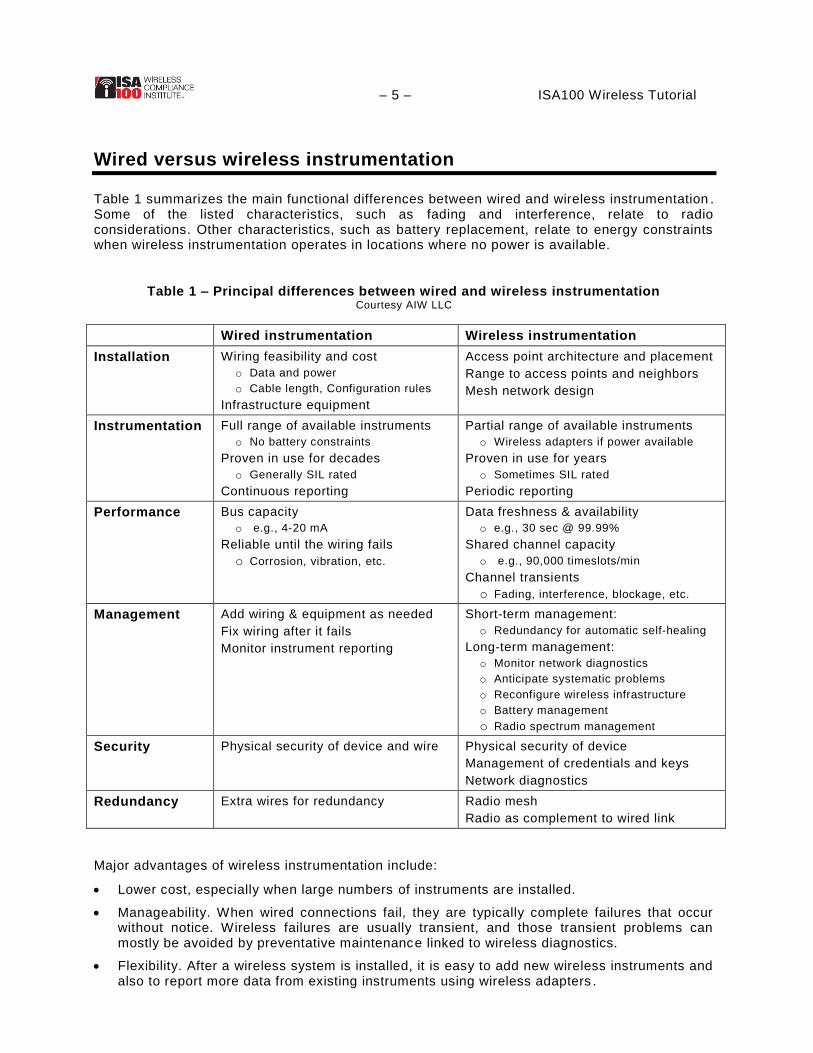
Table 1 summarizes the main functional differences between wired and wireless instrumentation . Some of the listed characteristics, such as fading and interference, relate to radio considerations. Other characteristics, such as battery replacement, relate to energy constraints when wireless instrumentation operates in locations where no power is available.
Table 1 – Principal differences between wired and wireless instrumentation Courtesy AIW LLC
Wired instrumentation Wireless instrumentation
Installation Wiring feasibility and cost
o Data and power
o Cable length, Configuration rules
Infrastructure equipment
Access point architecture and placement
Range to access points and neighbors
Mesh network design
Instrumentation Full range of available instruments
o No battery constraints
Proven in use for decades
o Generally SIL rated
Continuous reporting
Partial range of available instruments
o Wireless adapters if power available
Proven in use for years
o Sometimes SIL rated
Periodic reporting
Performance Bus capacity
o e.g., 4-20 mA
Reliable until the wiring fails
o Corrosion, vibration, etc.
Data freshness & availability
o e.g., 30 sec @ 99.99%
Shared channel capacity
o e.g., 90,000 timeslots/min
Channel transients
o Fading, interference, blockage, etc.
Management Add wiring & equipment as needed
Fix wiring after it fails
Monitor instrument reporting
Short-term management:
o Redundancy for automatic self-healing
Long-term management:
o Monitor network diagnostics
o Anticipate systematic problems
o Reconfigure wireless infrastructure
o Battery management
o Radio spectrum management
Security Physical security of device and wire Physical security of device
Management of credentials and keys
Network diagnostics
Redundancy Extra wires for redundancy Radio mesh
Radio as complement to wired link
Major advantages of wireless instrumentation include:
Lower cost, especially when large numbers of instruments are installed.
Manageability. When wired connections fail, they are typically complete failures that occur without notice. Wireless failures are usually transient, and those transient problems can mostly be avoided by preventative maintenance linked to wireless diagnostics.
Flexibility. After a wireless system is installed, it is easy to add new wireless instruments and also to report more data from existing instruments using wireless adapters .
– 6 – ISA100 Wireless Tutorial
Security. Wireless security extends to the field instrument and does not rely on physical security of the transmission medium. (Some fieldbus technologies assume that field wiring is secure and therefore have no cryptography on the field instrument.)
Redundancy within a wireless network. Typically, wired instrumentation relies on a single wire to each instrument, with various opportunities for failure . A well-designed wireless system has redundancy built in at all steps in the transmission chain without any failure -prone connectors. Field experience is demonstrating that a redundant wireless channel can be every bit as reliable as a non-redundant wired channel, particularly when wires are long and/or subjected to challenging conditions.
Redundancy at the plant level. A wireless system can add redundancy to wired reporting, with the same data reported through wired and wireless channels. Similarly, when field instrumentation is involved in an independent protection layer (IPL), wireless may provide an advantage if another IPL uses available wiring.
Table 1 also suggests a set of generally agreed-upon disadvantages of wireless instrumentation at this time. These considerations can be generally grouped as battery-related and radio-related.
Disadvantages of battery-powered operation include:
Battery maintenance. Battery maintenance of wireless devices constitutes a factor that somewhat offsets wireless cost savings. In addition, if battery maintenance is not performed correctly, the instrument will eventually fail . A well-designed wireless solution should ensure that battery replacement occurs in conjunction with an instrument’s general maintenance interval.
Limited wireless instrumentation. An ISA100 Wireless adapter can convert a wide range of wired instruments to wireless, but only if the wired instrument has the power to operate . In locations wherein wireless is needed, there may be no source of external DC power, and that limits the instrumentation options. For example, users have told this author that no battery -powered clamp-on flow sensor is available today (mid-2014). New wireless products are being rapidly released to meet market demand.
Continuous reporting. In some use cases, it is not technically feasible to sample and report process data continuously under battery power. ISA100 Wireless devices can be configured to report process data frequently in critical applications, with predictable battery life impacts, but only if the sensor has the energy to collect the data in the first place.
Disadvantages of radio operation include:
Procedural barriers. Wired instruments have been used for decades, and processes for specifying and approving wired systems are well-established at user sites. Many of these same users do not have clear processes for approving wireless, particularly when safety credit is involved.
Statistical nature of radios. Radio performance is statistical by nature, with packet errors and retries being fundamental considerations for any wireless system design. Performance requirements are probabilistic, for example, a data freshness requirement of 30 seconds with 99.99% availability. A well-designed wireless system will have plenty of margin built in, as well as extensive network diagnostics that detect loss of margin even while the system achieves its performance objectives.
Limited reporting rates. ISA100 Wireless is designed to support reporting as frequently as every 0.25 seconds with a transmission latency of 0.10 seconds in structured configurations. Faster reporting rates are considered (by the major standards) unsuitable for battery -powered operation at this time.
Spectrum management. Wireless instrumentation shares the radio spectrum with other systems and applications. Spectrum management generally needs to be considered when each new wireless system is installed, and should also be continuously monitored . As noted

– 7 – ISA100 Wireless Tutorial
above, a well-designed wireless system will have performance margins built in and will include extensive diagnostics to detect loss of margin due to radio interference and other considerations. ISA100 Wireless radio diagnostics include metrics that are specifically intended to detect and blacklist problematic radio channels automatically.
Based on real-world experience with all of these factors, users of industrial wireless are quickly learning that wireless can deliver more than adequate performance for a wide range of applications.
– 8 – ISA100 Wireless Tutorial
Use cases for industrial wireless instrumentation
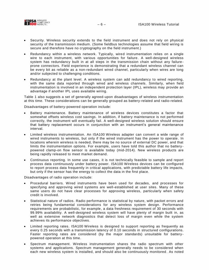
Industrial wireless instrumentation is being applied to a wide variety of applications today . Figure 2 represents one way to summarize concisely the major use cases.
Figure 2 – Current landscape of industrial wireless instrumentation Courtesy AIW LLC
The vertical axis shows types of applications, derived from ISA100 usage classes:
Monitoring and compliance applications track the status of equipment or a process state, such as temperature or vibration. Monitoring data is archived for subsequent review and may or may not be displayed to operators.
Alerts and alarms track the status of a process state, such as temperature, or a safety state, such as hydrocarbon gas level. Exceptions are reported to an operator for appropriate action.
In control applications, wireless is somehow involved in a control loop. “Open Loop” means that a user is in the loop; “Closed Loop” means that the loop is automated . Closed loop applications are sometimes divided into outer loop and inner loop.
In an automated safety instrumented function (SIF), a set of equipment is intended to reduce the risk of a specific hazard in an automated safety loop.
The green boxes in Figure 2 indicate where wireless instrumentation is targeted, in actual practice at this time (2014). This is intended as a statement of fact, not to imply that wireless is unsuitable for other applications. For example, ISA100 Wireless was designed for sub-second reporting rates, but sub-second timing is not shown in Figure 2 because few wireless instruments today are so configured. Similarly, wireless instrumentation for automated SIF is shown with a dotted line to suggest that it is feasible but not currently being adopted by many users.

– 9 – ISA100 Wireless Tutorial A given instrument might cover multiple use cases at the same time. For example, a temperature-monitoring instrument can be primarily intended to log compliance of a process state. In addition, when exceptions are detected, process alarms are reported to an operator , who can intervene by adjusting a valve. If the valve needs to be adjusted within 10 minutes of an exception, that would typically be classified an alarm. If response time is several hours, the application might be classified as an alert or as monitoring.
– 10 – ISA100 Wireless Tutorial
Equipment condition monitoring
Condition monitoring involves monitoring the condition of equipment in order to identify a developing fault. Condition monitoring may be applied to rotating machinery, steam traps, pipes, or other equipment. Candidates for wireless condition monitoring are items of equipment that are periodically inspected using handheld diagnostic tools, but that are subject to failure between inspections. Wireless instrumentation can provide more seamless visibility of equipment condition, allowing maintenance to be scheduled or other actions to be taken to prevent failure and/or avoid its consequences.
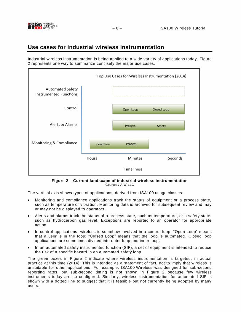
Rotating equipment is a commonly cited example of condition monitoring that is suitable for ISA100 Wireless. A plant may have hundreds or thousands of locations where in rotating equipment is subject to failure. Vibration sensors on rotating equipment can be used to predict failures, with enough notice so that preventative maintenance can prevent an o perational disruption.
Corrosion monitoring is another use case for industrial wireless . NDT (non-destructive testing) techniques are commonly used in periodic inspection of pipes and other equipment that is subject to corrosion. Similar capabilities are increasingly being offered in wireless products, providing an easily installed and easily moved corrosion monitoring capability at speeds approaching real-time.
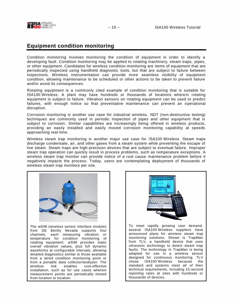
Wireless steam trap monitoring is another major use case for ISA100 Wireless. Steam traps discharge condensate, air, and other gases from a steam system while preventing the escape of live steam. Steam traps are high-precision devices that are subject to eventual failure. Improper steam trap operation can quickly result in process problems, such as temperature exceptions. A wireless steam trap monitor can provide notice of a root cause maintenance problem before it negatively impacts the process. Today, users are contemplating deployment of thousands of wireless steam trap monitors per site.
The wSIM (wireless sensor interface module) from GE Bently Nevada supports four channels, each measuring vibration or temperature for condition monitoring of rotating equipment. wSIM provides static overall vibration values, plus full dynamic waveforms at configurable intervals, allowing detailed diagnostics similar to those available from a wired condition monitoring point or from a portable data collector/analyzer. The wireless link enables cost-effective installation, such as for use cases wherein measurement points are periodically moved from location to location.
To meet rapidly growing user demand, several ISA100 Wireless suppliers have announced plans for wireless steam trap monitoring solutions. Shown is TrapMan from TLV, a handheld device that uses ultrasonic technology to detect steam trap faults. The technology in TrapMan is being adapted for use in a wireless sensor designed for continuous monitoring. TLV chose ISA100 Wireless because the standard and systems meet all of their technical requirements, including 15-second reporting rates at sites with hundreds or thousands of devices.
– 11 – ISA100 Wireless Tutorial
Process monitoring and compliance
Process monitoring involves tracking the status of a process or state where no immediate consequences are involved. Use cases include history collection, sequence-of-events logging, or event trapping with a long time scale for resolution.
Wellhead process monitoring is a common use case for wireless. A problem wellhead may be instrumented permanently or temporarily and data collected over a period of time to track performance or identify root cause problems. The wireless aspect makes it easy to instrument a wellhead temporarily and then relocate the wireless equipment to another wellhead as needed.
Remote wellhead monitoring is a potentially game changing application for upstream operation. A geographically distributed collection of brownfield wellheads can be retrofitted with wireless sensors, with process data transmitted to remote operations centers. On-site personnel can be deployed as needed to handle exceptional circumstances.
Process monitoring may be required to demonstrate process compliance, such as in chemical or pharmaceutical manufacturing. Wireless sensors periodically report temperature, pressure, or other data that is archived in a historian application, thereby demonstrating the compliance of a process.
Process monitoring is commonly combined with alarming. When sensor data is out of range, an alarm can be sent to an operator. When the required response time is long, such as 8 hours, the application may still be considered monitoring. Definitions vary in practice.
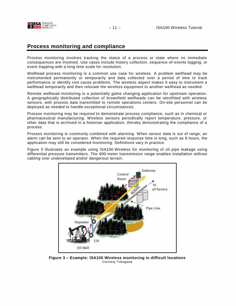
Figure 3 illustrates an example using ISA100 Wireless for monitoring of oil pipe leakage using differential pressure transmitters. The 600 meter transmission range enables installation without cabling over undeveloped and/or dangerous terrain.
Figure 3 – Example: ISA100 Wireless monitoring in difficult locations Courtesy Yokogawa
– 12 – ISA100 Wireless Tutorial
Alerts, alarms, and safety
Alarming involves an out-of-bounds condition that is reported to a user or system. Yokogawa Electronics Corporation has reported that over 50% of their wireless instrumentation projects require a 1-10 second update period. Cited applications include gas detection, fire detection, monitoring for operation (power), monitoring for safety (s teel), cold temperature monitoring (gas), and tsunami detection. All of these can be considered “alarming” applications .
Many users define the term “alarm” in alignment with ISA-18.2-2009, Management of Alarm Systems for the Process Industries . In that standard, an alarm is “an audible and/or visible means of indicating to the operator an equipment malfunction, process deviation, or abnormal condition requiring a response.” The essential element of this definition is the response to the alarm.
The term “alert” is generally used for applications with less rigorous requirements than alarms, for example maintenance alerts where the user response is not specific or time-critical.
According to IEC 61511-1, regarding safety alarms:
Where actions depend on an operator taking specific actions in response to an alarm (for example, opening or closing a valve), then the alarm shall be considered part of the safety instrumented system [SIS] (i.e., independent of the BPCS [Basic Process Control System]).
Where actions depend on an operator notifying maintenance to repair a faulty system in response to a diagnostic alarm, this diagnostic alarm may be a part of the BPCS but shall be subject to appropriate proof testing and management of change along with the rest of the SIS.
In practice, SIS alarms (by the definition above) are commonly used today. For example, a wireless gas detector alarm in the control room may require manual actions to evaluate the alarm, activate deluge, shut down processes, or other defined action.
A “safety-related alarm” designation can be applied to an alarming application that is a candidate for safety credit as an Independent Protection Layer. To simplify approvals, <0.9 availability may be claimed, thereby classifying an alarm as BPCS. Regardless of an alarm’s classification, high reliability is invariably a key objective.
It is well established that an alarm system must be designed for effective handling of individual alarms during normal operation and handling of many alarms during a major plant upset. ISA-18.2-2009 suggests that an average of 2 alarms per 10 minutes is the maximum manageable by a single operator and that rates approaching 10 alarms in 10 minutes may not be reliably sustainable by an operator for long periods. Wireless has the potential for supporting many more alarms than have been feasible in the past, so alarm management is an essential consideration in a scaled wireless implementation.
– 13 – ISA100 Wireless Tutorial
Gas sensing alarms
Gas sensing is an important use case for wireless alarming. The requirements vary by application and region. For example, the process safety time of response (t90) for hydrocarbon gas detection as required in IEC60079-29-1 is 60 seconds.
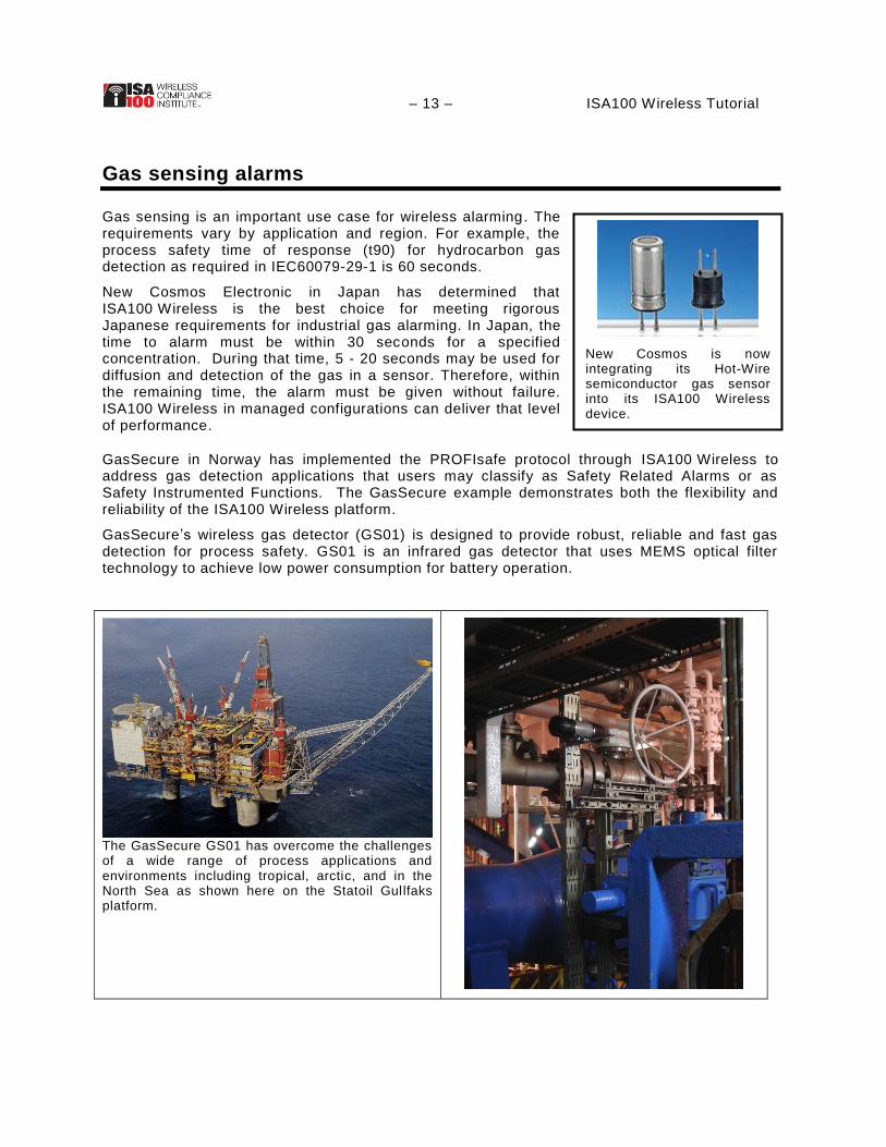
New Cosmos Electronic in Japan has determined that ISA100 Wireless is the best choice for meeting rigorous Japanese requirements for industrial gas alarming. In Japan, the time to alarm must be within 30 seconds for a specified concentration. During that time, 5 - 20 seconds may be used for diffusion and detection of the gas in a sensor. Therefore, within the remaining time, the alarm must be given without failure. ISA100 Wireless in managed configurations can deliver that level of performance.
GasSecure in Norway has implemented the PROFIsafe protocol through ISA100 Wireless to address gas detection applications that users may classify as Safety Related Alarms or as Safety Instrumented Functions. The GasSecure example demonstrates both the flexibility and reliability of the ISA100 Wireless platform.
GasSecure’s wireless gas detector (GS01) is designed to provide robust, reliable and fast gas detection for process safety. GS01 is an infrared gas detector that uses MEMS optical filter technology to achieve low power consumption for battery operation.
The GasSecure GS01 has overcome the challenges of a wide range of process applications and environments including tropical, arctic, and in the North Sea as shown here on the Statoil Gullfaks platform.
New Cosmos is now integrating its Hot-Wire semiconductor gas sensor into its ISA100 Wireless device.

– 14 – ISA100 Wireless Tutorial GS01 is integrated in a safety system using the PROFIsafe communication protocol through an ISA100 Wireless radio. The system is designed for use in Safety Instrumented Functions with a SIL2 (Safety Integrity Level) rating according to IEC61508.
Figure 4 – One implementation of PROFIsafe over ISA100 Wireless For gas detection with low latency
Courtesy of GasSecure
Figure 4 illustrates a simplified view of communication between a safety PLC and a GS01 gas detector through an ISA100 Wireless Gateway/Access Point . The GS01 answers PROFIsafe requests from the safety controller with responses containing the gas concentration measurement. If a gas concentration is detected, the response is sent immediately. During normal operation the response is delayed in order to slow down the message exchange for extended battery life.
PROFIsafe uses a “Black Channel” concept, which does not depend on the characteristics of the underlying transmission channels. The PROFIsafe protocol ensures correct message sequencing, message content, device address, and parameterization , without relying directly on assurances provided by the ISA100 Wireless protocol. Indirectly, the implementation relies on latency, reliability, and security that is intrinsic in the ISA100 Wireless channel.
Other ISA100 Wireless suppliers rely more directly on the highly reliable, secure, and time-stamped ISA100 Wireless communications protocol to achieve the mission critical requirements for alarming.
Across various techniques that are being implemented on ISA100 Wireless platforms, it is clear that a highly reliable and low latency communication is essential for typical alarming applications, especially when safety is involved.
– 15 – ISA100 Wireless Tutorial
Control over wireless
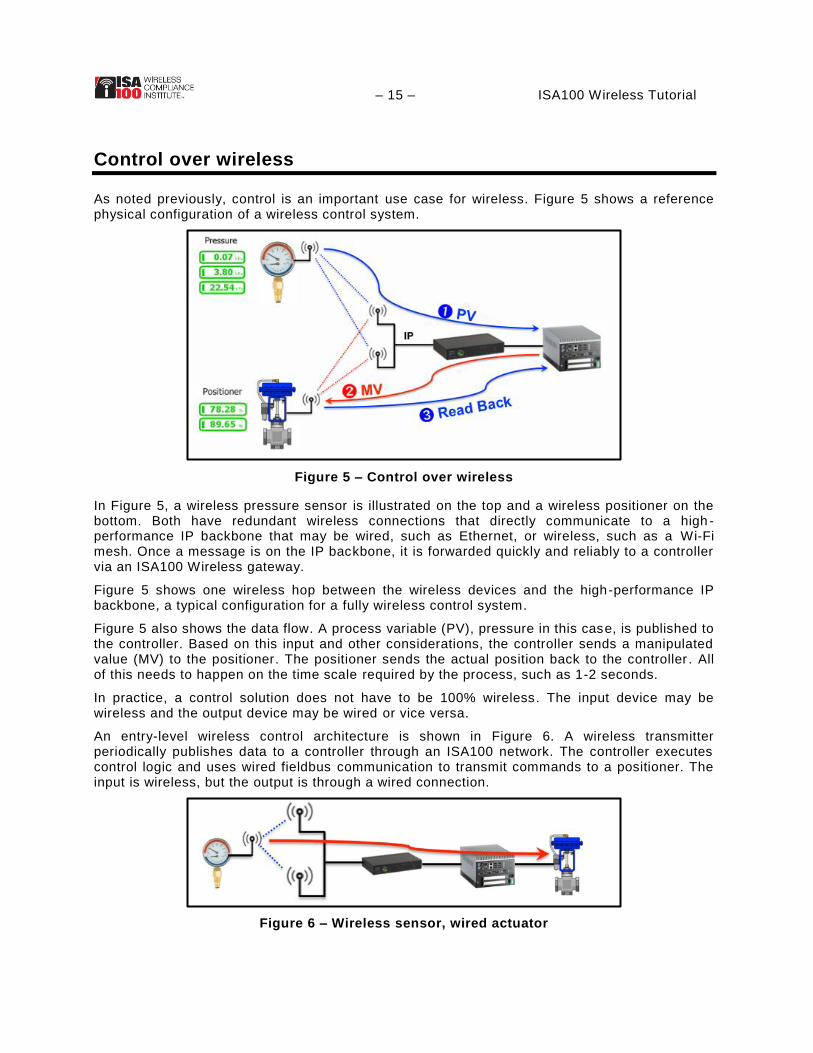
As noted previously, control is an important use case for wireless. Figure 5 shows a reference physical configuration of a wireless control system.
Figure 5 – Control over wireless
In Figure 5, a wireless pressure sensor is illustrated on the top and a wireless positioner on the bottom. Both have redundant wireless connections that directly communicate to a high -performance IP backbone that may be wired, such as Ethernet, or wireless, such as a Wi-Fi mesh. Once a message is on the IP backbone, it is forwarded quickly and reliably to a controller via an ISA100 Wireless gateway.
Figure 5 shows one wireless hop between the wireless devices and the high-performance IP backbone, a typical configuration for a fully wireless control system.
Figure 5 also shows the data flow. A process variable (PV), pressure in this case, is published to the controller. Based on this input and other considerations, the controller sends a manipulated value (MV) to the positioner. The positioner sends the actual position back to the controller . All of this needs to happen on the time scale required by the process, such as 1-2 seconds.
In practice, a control solution does not have to be 100% wireless. The input device may be wireless and the output device may be wired or vice versa.
An entry-level wireless control architecture is shown in Figure 6. A wireless transmitter periodically publishes data to a controller through an ISA100 network. The controller executes control logic and uses wired fieldbus communication to transmit commands to a positioner. The input is wireless, but the output is through a wired connection.
Figure 6 – Wireless sensor, wired actuator

– 16 – ISA100 Wireless Tutorial Figure 7 shows the reverse. On the right, a wired input device transmits sensor data to a controller, where control logic is executed. Then actuation occurs via a wireless link through an ISA100 network.
Figure 7 – Wired sensor, wireless actuator
Figure 8 shows a common configuration, with a wireless sensor providing secondary input. On the right, the primary loop is wired. On the left, a wireless sensor provides a secondary input that would be otherwise unavailable.
Figure 8 – Wireless sensor for secondary input
Early examples of control-related applications tend to be hybrids of wired and wireless. As users become more comfortable with wireless, fully wireless solutions can be realistically considered.

– 17 – ISA100 Wireless Tutorial
Control over wireless – Latency requirements
What are the latency requirements for control? In a baseline wireless control scenario, shown in Figure 9, one device publishes data to another device at regular intervals, and the other device receives that signal and does something useful with the information. A third device might serve as a controller, and/or control logic may reside in the devices themselves .
Figure 9 proposes that something on the order of 1-second latency, end-to-end, should be the basic performance reference for control .
Figure 9 – Latency requirements for control
As an example of latency requirements for control, consider a human-in-the-loop of a control application, shown in Figure 9 as a person pressing a button. Normally, users require feedback; it is well known that when a response time exceeds about 2 seconds, the user’s attention will start to drift and/or the user will start to doubt the reliability of the action . Therefore, 1-2 seconds end-to-end is a reasonable target for incorporating a human-in-the-loop in a control schema, and in practice, 1-second latency is common in ISA100 Wireless solutions and systems intended for control.
As another example, consider an automated control scenario, shown in Figure 9 as a pressure sensor feeding data to a valve controller. Generally, the scan period should be some fraction of the lag in the process response. ISA100 Wireless system suppliers typically suggest a value of roughly 5%. For example, to prevent excessive valve activity in the presence of higher frequency noise, one might reasonably make the period between scans less than one-tenth of the dead time, or one-twentieth of the lag in the process response. In practice, this tends to result in numbers in the range of 5%.
Although some applications require lower or higher performance, ISA100 was designed under the principle that 1-second latency covers a reasonable range of applications without involving painful tradeoffs or asking the user to apply unproven control concepts in plant operation. Maintaining and supporting existing operating principles is one of the key benefits of using ISA100 technology.
– 18 – ISA100 Wireless Tutorial
The ISA100 standard
Founded in 1945, the International Society of Automation (ISA) is a global, nonprofit organization. Based in Research Triangle Park, North Carolina, ISA develops standards, certifies industry professionals, provides education and training, publishes books and technical articles, and hosts conferences and exhibitions for automation professionals.
In 2005, ISA formed the ISA100 Committee to establish standards, recommended practices, technical reports, and related information that will define technologies and procedures for implementing wireless systems in the automation and control environment with a focus on the field level. ISA100 .11a is the first project in the ISA100 family. It defines the OSI layer specifications (physical layer, network layer, etc.), security specifications, and manag ement (including network and device configuration), intended for sensors and actuators serving ISA100 application classes 1 through 5 (control, alerting, and monitoring) and optionally class 0 (safety) for fixed and portable devices.
The project’s applicat ion focus addresses performance needs for low-energy field devices used for periodic monitoring and process control wherein latencies on the order of 100 ms can be tolerated in constrained configurations. Mesh, star, and hybrid configurations are supported in scaled systems.
ISA100 Wireless (ISA100.11a / IEC 62734) is an international, industrial wireless networking and communications standard engineered to serve the needs of process industries. With native IPv6 networking and object architecture, ISA100 Wireless extends the Industrial Internet of Things (IIOT) to wireless. End users can select ISA100 Wireless Compliant™ devices from a best -of-breed pool of suppliers with assurances of device interoperability. ISA100 Wireless enables automation engineers to quickly create, modify, optimize, and scale wireless networks that are open, interoperable, and reliable for their most critical applications.
Built from the ground up and driven by user requirements, the ISA100 Wireless standard received formal ANSI approval in January 2012 and approval as IEC 62734 and EN 62734 in September 2014. ISA100 Wireless is the only IPv6, 6LowPAN industrial protocol designed for industrial automation. ISA100 Wireless meets requirements of ETSI EN 300 328 v1.8.1 for coexistence with nearby 2.4 GHz radio devices.
ISA100 Wireless Compliance Institute
In 2006, ISA formed a separate and independently managed organization, the ISA100 Wireless Compliance Institute (WCI), to establish essential specifications and processes to be used in the testing and certification of wireless products and systems for the ISA100 family of standards . The relation of ISA100 and WCI is roughly analogous to IEEE 802.11 and Wi-Fi. ISA100’s mission is to create standards, recommended practices, technical reports, and related information. WCI’s mission is to decrease the time, costs, and risks of developing and deploying standards-based industrial wireless devices and systems by establishing a collaborative industry-based program among users, suppliers, and other stakeholders. WCI conducts independent testing and certification of wireless devices and systems for the ISA100 Wireless Systems. WCI provides education, tools, and technical support to users and suppliers in the design, certification, deployment, and management of wireless devices and systems that utilize the ISA100 family of standards. It accelerates and facilitates adoption of ISA100 standards by certifying that wireless devices and systems meet a common set of specifications.
WCI and its members have adopted the brand name ISA100 Wireless™ to encompass the ISA100.11a-2011 standard as certified by WCI and various WCI-defined extensions to that baseline.

– 19 – ISA100 Wireless Tutorial
ISA100 Wireless and the Internet of Things
ISA100 Wireless was designed as an extension of the Internet, building on the IPv6 “Internet of Things” standard. IPv6 is an addressing scheme that allows an essentially unlimited number of devices to be individually addressable. Collections of devices can still be segregated as needed for security and manageability, but with IPv6, addressing considerations are no longer a constraint. Most forecasts suggest that tens of billions of devices will be Internet-accessible within a decade. With its use of IPv6, ISA100 Wireless is well-positioned to ride that wave.
Using IPv6, ISA100 Wireless supports multiple subnets, enabling sensors to be grouped together much like a VLAN for traffic and network management while breaking the network into zones for security. Subnet-level mesh and backbone-level routing are also supported. Internet Protocol Security (IPsec), developed in conjunction with IPv6, authenticates and encrypts each IP packet of a communication session to protect application traffic across an IP network.
IPv6 networks use familiar standards-based addressing and can be managed using tools derived from traditional IT network management tools and systems. Today’s generation of network managers and automation engineers understand IPv6, and so will future generations.
ISA100 Wireless is an open, flexible framework that accommodates legacy applications regardless of protocol, thus protecting an end user’s existing application investments. The communication layering in ISA100 Wireless matches the OSI layering of the Internet, simultaneously accommodating multiple protocols within a single, interoperable network through the ISA100 Wireless object-oriented application model. Examples available today include: GasSecure gas sensor (PROFIsafe for enhanced security); 3eTi network nodes (FIPS 140-2 for military grade security); GE Bently Nevada Vibration sensors (proprietary protocol); and Honeywell Enraf radar level gauge (proprietary protocol).
Figure 10 illustrates the flexibility of the ISA100 Wireless universal network in an example mesh network comprised of devices from multiple manufacturers, some of which use the native ISA100 Wireless protocol while others use ISA100 objects with different protocols at the same time. The two legacy HART devices, wired to a controller, are simultaneously reporting HART digital data to the ISA100 Wireless network via ISA100 Wireless HART adapters.
Figure 10 – Flexibility of ISA100 Wireless network

– 20 – ISA100 Wireless Tutorial
ISA100 Wireless structured and ad hoc methodologies
The “Internet of Things” approach in ISA100 Wireless impacts network architecture and the user experience in actual practice.
Figure 11 shows a structured network design that leverages IP. The ISA100 Wireless network is shown as a single cloud or mesh with multiple IP backbone connections. In this configuration, multiple gateways are shown as Internet appliances without a radio. ISA100 Wireless messages flow over the IP network. Networks of this kind are generally rolled out using a structured methodology, similar to the way a Wi-Fi or cellular network is typically deployed.
Figure 11 – ISA100 structured network design: One network scaled through an IP backbone
Figure 12 shows an ad hoc network design. A collection of small networks are installed over time, typically single-purpose networks. Each network is attached to a device called a “Gateway .” The diagram shows that each gateway also hosts a management function . In this configuration, each gateway has a radio and no backbone is involved in each wireless network. At each gateway, the data is translated to something completely different, such as Modbus or OPC. The connections on the other side of the gateway are shown as a series of question marks, suggesting that the high-side interface is not specified by the standard and could be just about anything.
Figure 12 – ISA100 ad hoc network design: Multiple small networks scaled by duplication
ISA100 Wireless is designed to scale through IP. In practice, small systems or evaluation systems will tend to use ad hoc methodologies as illustrated in Figure 12. However, as systems scale, it is expected that users will prefer to leverage the IP backbone as illustrated in Figure 11. Ad hoc systems tend to be rolled out organically, one project at a time, and can result in unmanageable chaos at scale. For example, unplanned battery failure and communication path instability are typical symptoms of an ad hoc methodology that is inappropriately scaled.
– 21 – ISA100 Wireless Tutorial
Building blocks of an ISA100 Wireless network
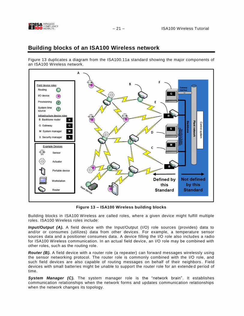
Figure 13 duplicates a diagram from the ISA100.11a standard showing the major components of an ISA100 Wireless network.
Figure 13 – ISA100 Wireless building blocks
Building blocks in ISA100 Wireless are called roles, where a given device might fulfill multiple roles. ISA100 Wireless roles include:
Input/Output (A). A field device with the Input/Output (I/O) role sources (provides) data to and/or or consumes (utilizes) data from other devices. For example, a temperature sensor sources data and a positioner consumes data. A device filling the I/O role also includes a radio for ISA100 Wireless communication. In an actual field device, an I/O role may be combined with other roles, such as the routing role.
Router (B). A field device with a router role (a repeater) can forward messages wirelessly using the sensor networking protocol. The router role is commonly combined with the I/O role, and such field devices are also capable of routing messages on behalf of their neighbors . Field devices with small batteries might be unable to support the router role for an extende d period of time.
System Manager (C). The system manager role is the “network brain”. It establishes communication relationships when the network forms and updates communication relationships when the network changes its topology.
– 22 – ISA100 Wireless Tutorial Security Manager (D). The security manager role is a specialized function that establishes secure sessions between network entities based on shared secrets . ISA100 Wireless is carefully designed so that RADIUS or other technology can be used for authentication services without exposing secret material to the system manager.
Backbone Router or Access Point (E). A device with the backbone routing role acts as an OSI Layer 3 interface between the wireless network and an IP backbone. An ISA100 Wireless backbone router is commonly called an “access point”, and in practice the terms are interchangeable.
Gateway (F). A device with the gateway role describes the function that translates ISA100 Wireless messages to other formats such as Modbus or OPC.
These logical roles can be, and often are, combined in actual devices. For example, the gateway (F), system manager (C), and security manager (D) roles may be combined into one device, commonly marketed as a “gateway” . Such a “gateway” may also include a radio link for direct wireless communication with the mesh by incorporating a backbone router (E) role, all in a single infrastructure device. As another example, the I/O role (A) and router role (B) are commonly supported and active in wireless field devices.
– 23 – ISA100 Wireless Tutorial
ISA100 Wireless performance
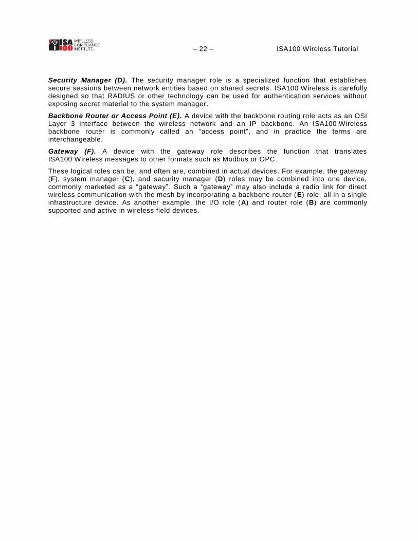
Figure 14 shows a conceptual picture of an ISA100 network . Exact features will vary depending on particular products and configurations, but the general principles apply across a range of solutions.
Figure 14 – Performance in an ISA100 Wireless network
A. Backbone: A backbone network is shown that provides sub-second latency, which is
typical for various IP-based solutions. The backbone may itself be wireless, such as a
Wi-Fi mesh, an LTE digital umbrella, or a point-to-point solution. While different
backbone solutions provide a variety of performance parameters, the principle is that
backbones usually provide higher performance than is available in a battery-operated
device mesh.
B. Star to Backbone: Some devices are shown connected to the backbone in a redundant
star configuration, with each device having multiple backbone connections. For control
applications, ISA100 is intended to offer sub-second latency and high reliability in that
configuration. For example, a “duocast” feature simultaneously transmits messages to
multiple backbone connections to improve the probability that a given transmission will
be received by the backbone and then forwarded.
C. Device Mesh Network: On the same network, but with lower priority, a device mesh
supports a population of devices with performance requirements measured in 10s of
seconds.
D. Peer-to-Peer: Mesh devices that are in proximity to each other may be configured to
communicate directly, not through the mesh, and thereby provide point -to-point
performance that is measured in seconds.

– 24 – ISA100 Wireless Tutorial In actual practice, the “Device Mesh Network” performance can also be in the ±1 second range in structured configurations. Device mesh performance is primarily constrained by energy limitations of devices that participate in the mesh. For example, when a battery-powered field device is configured to provide frequent routing services to neighboring devices, that reduces the device’s energy budget to perform its primary function (e.g. , to measure and report a level). When ±10 second numbers describe device mesh performance, this usually reflects a design that protects the battery life of routers. Suppliers have addressed this by introducing specialized devices in the mesh to act exclusively or primarily as repeaters and/or by limiting the number of nodes supported per repeater. The Sky Mesh concept, described subsequently in this paper, is a good example of battery-powered repeaters providing ±1 second performance in structured configurations.
The next two sections show how two major ISA100 Wireless suppliers arrange these building blocks to achieve a scalable “Internet of Things” network architecture.

– 25 – ISA100 Wireless Tutorial
An ISA100 Wireless IP-scaled network architecture
ISA100 Wireless has an IP-based architecture, allowing for backbone-leveraged scalability using technologies that are as diverse as the Internet itself . This section of the tutorial shows a real-world example of this approach put into practice: Sky Mesh from Yokogawa.
Yokogawa’s first proprietary wireless devices were implemented in 2005 . In 2008, after extensive field trials, the ISA100 Wireless protocol was selected, and Yokogawa’s first ISA100 Wireless products were released in 2010. Today (2014), Yokogawa systems have been deployed in 500+ projects. Over 50% of these projects utilize fast update rates of <10 seconds , especially for time-critical alerts.
Figure 15 summarizes Yokogawa’s available network options (in 2014).
Figure 15 – Summary of Yokogawa network options
Following the ISA100 Wireless paradigm, a redundant gateway provides the network brain for up to 20 subnets through IP backbone connections to ISA100 Wireless access points (backbone routers). Up to 500 field devices are supported per gateway at a 5-second update rate. As shown in Figure 15, supported backbone connections include Ethernet, Wireless LAN, Optical Ethernet, and 2-wire (4-20 mA) cable. Each backbone router can support up to 100 devices at 10-second update rates in mesh configurations. Available system components include:
Field Wireless Management Station: Provides gateway, system manager, and security
functions for up to 500 field devices at a 5-second update rate. Modbus, OPC, and GCI
(ISA100 Wireless) interfaces are supported. Up to 20 subnets are supported through up
to 20 backbone-connected access points. Each subnet may have up to 8 access points.
Up to 500 devices (100 per subnet) are supported at 5-second update rate (star and
mesh configuration). Up to 200 devices (20 per subnet) are supported at 1 -second
update rate (star configuration. Redundancy is supported, whereby management stations
are installed in pairs with seamless cutover if one fails.
– 26 – ISA100 Wireless Tutorial
Field Wireless Access Point: Provides ISA100 Wireless backbone router functions in
conjunction with a Field Wireless Management Station. Duocast is supported, whereby a
single message from a field device is received redundantly by two access points and
forwarded to the gateway. Gateway connections may be established using Ethernet,
Wireless LAN, Optical Ethernet, or 2-wire (4-20 mA) cable.
In addition, Yokogawa system diagrams usually show a “Repeater”, which may also be an I/O device such as a temperature sensor. A battery-powered repeater will support up to 15 I/O devices, with reporting rate constrained by battery life.
Yokogawa also offers an integrated gateway (not shown in the diagram) for smaller networks supporting up to 50 devices.
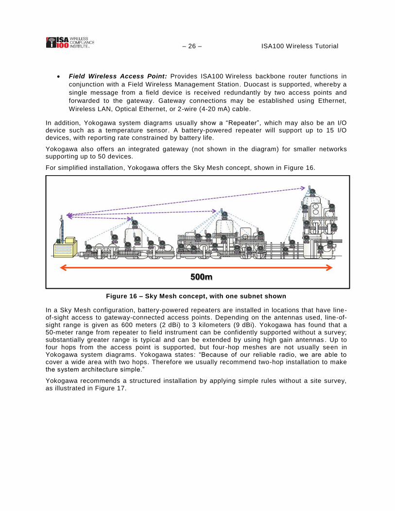
For simplified installation, Yokogawa offers the Sky Mesh concept, shown in Figure 16.
Figure 16 – Sky Mesh concept, with one subnet shown
In a Sky Mesh configuration, battery-powered repeaters are installed in locations that have line-of-sight access to gateway-connected access points. Depending on the antennas used, line-of-sight range is given as 600 meters (2 dBi) to 3 kilometers (9 dBi). Yokogawa has found that a 50-meter range from repeater to field instrument can be confidently supported without a survey; substantially greater range is typical and can be extended by using high gain antennas . Up to four hops from the access point is supported, but four -hop meshes are not usually seen in Yokogawa system diagrams. Yokogawa states: “Because of our reliable radio, we are able to cover a wide area with two hops. Therefore we usually recommend two-hop installation to make the system architecture simple.”
Yokogawa recommends a structured installation by applying simple rules without a site survey, as illustrated in Figure 17.

– 27 – ISA100 Wireless Tutorial
Figure 17 – Sky Mesh installation method
Experience with over 800 site installation experiences has demonstrated that Yokogawa’s Sky Mesh installation method results in 93% successful achievement of proper and stable connections to the gateway. The remaining 7% are mostly Wi-Fi interference cases, which are avoidable but involve additional procedures when they occur.
The Sky Mesh concept is workable at any scale. The concept can be applied to just a few devices in a remote cluster or hundreds of devices spread across an extensive site . The installation rules focus on the connection between a field device and in IP backbone and are as scalable as the IP backbone itself.
– 28 – ISA100 Wireless Tutorial
An ISA100 Wireless multi-purpose network architecture
The previous example showed how ISA100 Wireless can leverage an existing IP backbone. In an alternative IP-based network architecture ISA100 Wireless can also be integrated into a multi-purpose IP network. This section of the tutorial shows a real-world example of a multi-purpose network in practice: OneWireless from Honeywell.
OneWireless is Honeywell’s industrial network architecture. Honeywell has been providing wireless sensing solutions for over 10 years . Their OneWireless brand was established in 2007, with more than a billion operating hours to date (2014).
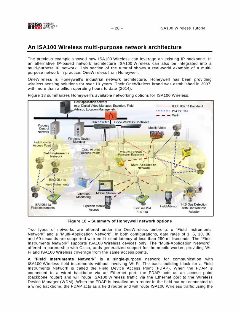
Figure 18 summarizes Honeywell’s available networking options for ISA100 Wireless.
Figure 18 – Summary of Honeywell network options
Two types of networks are offered under the OneWireless umbrella: a “Field Instruments Network” and a “Multi-Application Network”. In both configurations, data rates of 1, 5, 10, 30, and 60 seconds are supported with end-to-end latency of less than 250 mil liseconds. The “Field Instruments Network” supports ISA100 Wireless devices only. The “Multi-Application Network”, offered in partnership with Cisco, adds generalized support for the mobile worker, providing Wi-Fi and ISA100 Wireless coverage from the same access points.
A “Field Instruments Network” is a single-purpose network for communication with ISA100 Wireless field instruments without involving Wi-Fi. The basic building block for a Field Instruments Network is called the Field Device Access Point (FDAP). When the FDAP is connected to a wired backbone via an Ethernet port, the FDAP acts as an access point (backbone router) and will route ISA100 Wireless traffic via the Ethernet port to the Wireless Device Manager (WDM). When the FDAP is installed as a router in the field but not connected to a wired backbone, the FDAP acts as a field router and will route ISA100 Wireless traffic using the

– 29 – ISA100 Wireless Tutorial ISA100 Wireless protocol. The FDAP is not battery powered in either configuration, and therefore can support many field devices at high reporting rates without energy bottlenecks.
The FDAP has two ISA100 Wireless antennas, providing spatial diversity for improved range, claimed to provide a range improvement of 1.5x as compared to a single access point without diversity. The intent is to install FDAPs so that at least one is within range of most field instruments, with most of the ISA100 Wireless communication occurring directly through the FDAPs.
Field devices can also route on behalf of their neighbors when a direc t FDAP connection is not available. The system supports mesh configurations per the ISA100 Wireless standard. Honeywell supports a maximum of 4 wireless network hops between an access point and a field device.
A Wireless Device Manager (WDM) covers gateway, system manager, and security manager roles. A Honeywell WDM does not include a radio; it communicates with access points via Ethernet. A WDM currently supports up to 40 access points, 40 ISA100 routers, and 100 ISA100 field instruments.
Two WDMs can be configured as a redundant pair, consisting of a primary and a secondary WDM. The secondary WDM switches to the primary role if a software or hardware failure occurs on the primary WDM.
The user experience to integrate and implement wireless devices into Experion is like wired devices. A Honeywell WDM provides interfaces for Modbus, OPC-UA, OPC-DA, CDA (Experion), HART, GCI (ISA100 Wireless), and others. Users of Honeywell Experion PKS R410 or higher can add and configure ISA100 field devices to their con trol systems.
A “Multi-Application Network” is a multi-purpose network used to communicate with
ISA100 Wireless field instruments and Wi-Fi devices. As shown in Figure 18, Wi-Fi is also used
for backhaul.
The basic building block for a Multi-Application Network is the Cisco Aironet 1552S Outdoor Access Point. The 1552S merges an outdoor IEEE 802.11a/b/g/n access point with the capabilities of a Honeywell FDAP (described above). An installed 1552S provides both Wi-Fi and ISA100 Wireless coverage, thereby supporting wireless mobile stations, wireless video surveillance, wireless portable gas detectors, personnel location, and various other Wi-Fi applications with the same infrastructure that supports ISA100 Wireless. Wi-Fi performance is up to 300 Mbps. IEEE 802.11 wireless radios in the 1552S form a mesh network with each other that can be used for backhaul, as shown in Figure 18.
The ISA100 side of the 1552S is essentially the same as the FDAP described previously, configured as an ISA100 Wireless access point and using IEEE 802.11 wireless for backhaul.
When 1552S access points are in a configuration, they are managed through the WDM.
The combination of Wi-Fi and ISA100 Wireless access points is consistent with Honeywell’s vision of one network that can support a wide range of applications. Wi-Fi can be used to support full connectivity to wireless workers, security cameras, and so forth, while at the same time the ISA100 Wireless network supports a broad range battery-powered industrial instruments. Access point coverage designed to support Wi-Fi can also cover ISA100 Wireless, with ISA100 Wireless coverage easily extensible using ISA100 Wireless field routing and field device meshing.
– 30 – ISA100 Wireless Tutorial
ISA100 Wireless ecosystem
Until recently, only a few large vendors were able to assemble the expertise and resources to develop ISA100 Wireless instruments. Support for ISA100 Wireless by a greater diversity of suppliers is growing due to increased user demand, maturity of the supply chain, and new technologies.
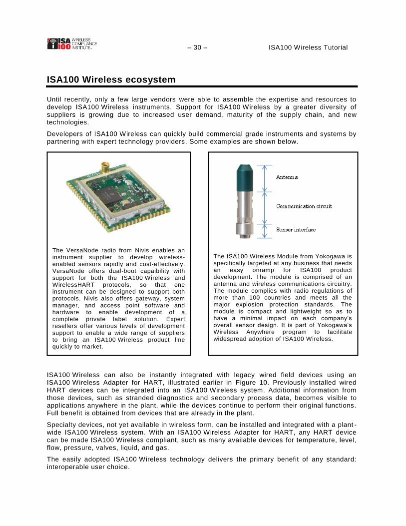
Developers of ISA100 Wireless can quickly build commercial grade instruments and systems by partnering with expert technology providers. Some examples are shown below.
ISA100 Wireless can also be instantly integrated with legacy wired field devices using an ISA100 Wireless Adapter for HART, illustrated earlier in Figure 10. Previously installed wired HART devices can be integrated into an ISA100 Wireless system. Additional information from those devices, such as stranded diagnostics and secondary process data, becomes visible to applications anywhere in the plant, while the devices continue to perform their original functions. Full benefit is obtained from devices that are already in the plant.
Specialty devices, not yet available in wireless form, can be installed and integrated with a plant -wide ISA100 Wireless system. With an ISA100 Wireless Adapter for HART, any HART device can be made ISA100 Wireless compliant, such as many available devices for temperature, level, flow, pressure, valves, liquid, and gas.
The easily adopted ISA100 Wireless technology delivers the primary benefit of any standard: interoperable user choice.
The ISA100 Wireless Module from Yokogawa is specifically targeted at any business that needs an easy onramp for ISA100 product development. The module is comprised of an antenna and wireless communications circuitry. The module complies with radio regulations of more than 100 countries and meets all the major explosion protection standards. The module is compact and lightweight so as to have a minimal impact on each company’s overall sensor design. It is part of Yokogawa’s Wireless Anywhere program to facilitate widespread adoption of ISA100 Wireless.
The VersaNode radio from Nivis enables an instrument supplier to develop wireless-enabled sensors rapidly and cost-effectively. VersaNode offers dual-boot capaibility with support for both the ISA100 Wireless and WirelessHART protocols, so that one instrument can be designed to support both protocols. Nivis also offers gateway, system manager, and access point software and hardware to enable development of a complete private label solution. Expert resellers offer various levels of development support to enable a wide range of suppliers to bring an ISA100 Wireless product line quickly to market.
– 31 – ISA100 Wireless Tutorial
Conclusion
Industrial wireless instrumentation is now at a stage where major users are rolling out ISA100 Wireless programs. The “tipping point” for industrial wireless occurs when major users switch from an ad hoc approach to wireless campaigns. In a bottom-up ad hoc approach, small wireless systems are installed one-by-one to address specific problems, relying on the passion of proactive early adopters. In a top-down campaign, solutions are rolled out to support enterprise strategy. A good process allows for both approaches, with successful ad hoc sys tems being a laboratory for future wireless campaigns.
Industrial wireless instrumentation is widely considered suitable for monitoring, control , and alarms, including safety alarms. Systems may be deployed using an ad hoc methodology to get started, but users are better served when systems are scaled using a more structured methodology that leverages the “Internet of Things.” User acceptance of and demand for IP-based scaled mission-critical wireless technology is driving adoption of ISA100 Wireless. ISA100 Wireless is poised to support a fast growth curve with its open design, scalable system and product architectures, and a vendor-neutral ecosystem.
References
Christensen, Clayton M., The Innovator’s Dilemma: When New Technologies Cause Great Firms to Fail, Harvard Business School Press, Boston, 1997, ISBN 0-87584-585-1.
“Industrial Wireless Instrumentation: Adoption Considerations ”, Paul Sereiko and Jay Werb, ISA 2014 Process Control and Safety Symposium, October 2014.
“Control Over Wireless: Current Applications and Future Opportunities ”, Jay Werb and Soroush Amidi, ISA100 Wireless Compliance Institute web site, presented at Automation Week 2012.
“ISA100 Wireless Adapter for HART”, Jay Werb, WCI web site, April 2013.
“Architecture for Industrial Internet of Things”, ISA100 Wireless Technical Brochure, WCI web site, April 2014.
Product information was provided and validated by suppliers.