How to calculate the value of resistor for LED _ LED’s Circuits.pdf
Upload
mukesh-kumarCategory
view
224download
2
Disclosure to Promote the Right To Information
Whereas the Parliament of India has set out to provide a practical regime of right to information for citizens to secure access to information under the control of public authorities, in order to promote transparency and accountability in the working of every public authority, and whereas the attached publication of the Bureau of Indian Standards is of particular interest to the public, particularly disadvantaged communities and those engaged in the pursuit of education and knowledge, the attached public safety standard is made available to promote the timely dissemination of this information in an accurate manner to the public.
इंटरनेट मानक
“!ान $ एक न' भारत का +नम-ण”Satyanarayan Gangaram Pitroda
“Invent a New India Using Knowledge”
“प0रा1 को छोड न' 5 तरफ”Jawaharlal Nehru
“Step Out From the Old to the New”
“जान1 का अ+धकार, जी1 का अ+धकार”Mazdoor Kisan Shakti Sangathan
“The Right to Information, The Right to Live”
“!ान एक ऐसा खजाना > जो कभी च0राया नहB जा सकता है”Bhartṛhari—Nītiśatakam
“Knowledge is such a treasure which cannot be stolen”
“Invent a New India Using Knowledge”
है”ह”ह
IS 9499 (1980): Conventions concerning electric andmagnetic circuits [ETD 1: Basic Electrotechnical Standards]

I!3 :9499-1980
Indian Standard CONVENTIONS CONCERNING
ELECTRIC AND MAGNETIC CIRCUITS
Electrotechnical Standards Sectional Committee, ETDC 1
Chainnan
SHRI J. S. ZAVERI
Members
SHRI H. V. BADRINATH
SHRI V. K. BATRA SHRI T. L. BHATIA
SHRI J. M. NEO~Y ( A&mate ) SHRI V. S. BHATIA
BRIGN. DAYAL COL K. V. KUDVA ( Alternate )
DIRECTOR ( TED )
Representing
Bharat Bijlee Ltd, Bombay; and Rotating Machinery Sectional Committee, ETDC 15, IS1
Wireless Planning and Coordination Wing ( Ministry of Communications ), New Delhi
National Physical Laboratory ( CSIR ), New Delhi Indian Posts and Telegraphs Department ( Ministry
of Communications ), New Delhi
Low Voltage Switchgear and Controlgear Sectional Committee, ETDC 57, IS1
Ministry of Defence ( DGI )
Central Electricity Authority ( Department of Power ) ( Ministry of Energy ), New Delhi **_ . .
DEPUTY DIRECTOR ( TED ) ( Alternate ) SHRI M. L. DONGRE Power Cables Sectional Committee, ETDC 59, IS1 SHRI R. D. JAIN Conductors and Accessories for Overhead Liner
Sectional Committee. ETDC 60. IS1 SHRI K. C. KAUL Bharat Heavy Electricals Ltd, Bhopal
SHRI PRAKASH SINCH ( Alternate) SHRI S. K. MUKHERJ~E National Test House, Calcutta
SHRI B. MUKHOPADHYAY ( Alternate ) PROF R. C. NARAYANAN General Nomenclature and Symbols Subcommittee,
ETDC 1: 3, ISI SHRI D. V. NARKE Transformers Sectional Committee, ETDC 16, IS1 SHRI H.M. PA1 High Voltage Switchgear and Controlgear Sectional
Committee, ETDC 58, IS1 SHRI R. RADHAKRISHNAN Central Electrochemical Research Institute
( CSIR ), Karaikudi SHRI H. N. VENKOBARAO ( Alternate)
SHRI T. S. M. RAO Relays Sectional Committee, ETDC 35, IS1 SHRI V. L. SASTRY Electronics and Radar Development Establishment
SHRI K. V. BHAT ( Alternate) ( Ministry of Defence ), Bangalore
( Continued on page 2 )
Q Cop@ghr 1981 INDIAN STANDARDS INSTITUTION
This publication is protected under the Indian Copyright Act (XIV of 1957) and reproduction in whole or in part by any means except with written permission of the publisher shall be deemed to be an infringement of copyright under tho said Act
1s : 9499 i 1980
( Continued frompage 1 )
Members k?~resentinlJ
DR S. M. SEN DR H. V. K. UDUPA
institution of Engineers ( India), Calcutta Secondary Cells and Batteries Sectional Committee,
ETDC 11, IS1 SHRI: M. P. WAGli Indian Electrical Manufacturers’ Association,
SHRI S. D. MEDHEKAR (Alternate) Bombay
SHRI S. P. SACHDEV, Director ( Elec tech ) (Sccretaary )
Director General, IS1 ( Ex-of&sir Member)
2
IS : 9499 - 1980
Indian Standard CONVENTIONS CONCERNING
ELECTRIC AND MAGNETIC CIRCUITS
0. FOREWORD
0.1 This Indian Standard was adopted by the Indian Standards Institution on 20 March 1980, after the draft finalized by the Electrotechnical Standards Sectional Committee had been approved by the Electrotechnical Division Council.
0.2 Sign conventions are necessary to interpret a circuit equation. This standard covers the conventions concerning electric and magnetic circuits in the following two sections:
Section 1 Conventions concerning the signs of quantities in electric and magnetic circuits in general
Section 2 Conventions concerning electric and magnetic circuits under sinusoidal conditions
0.3 The chief aim of Section 1 is to recommend:
a)
b>
conventions on the meaning in a circuit of the positive or negative character of a current, voltage, electromotive force, electric charge and magnetic flux; and conventions on the methods of indicating in circuit diagram, by graphical symbols or by subscripts accompanying letter symbols, the sign conventions for the quantities mentioned in (a) above.
0.3.1 In Section 1 no rule is given for associating the sign conventions of different quantities in the same circuit, nor for writing the equations of a complete network. Where sign conventions are indicated by arrows, no directive is given as to the form that the arrows should take.
0.3.2 The quantities in question are usually functions of time. The conventions in Section 1 concern instantaneous values. They can be applied to complex quantities representing sinusoidal quantities, because for such quantities it is possible by means of simple rules to transform equations relating instantaneous values into those relating complex values.
0.3.3 Section 1 gives examples of each recommended method of indica- ting the reference direction or reference polarity for quantities taken singly. More complicated examples, associating indications of the reference direc- tions or reference polarities of several quantities in the same diagram, are given in Appendix A.
3
IS : 9499 - 1980
0.4 Section 2 of this standard is aimed at covering conventions concerning electric and magnetic circuits under sinusoidal conditions. Throughout Section 2, time t is used as the independent variable, but this could be some other quantity. Sinusoidal quantities are expressed in the form of cosines, but the use of sines, with obvious consequent modifications, is not debarred. It should also be noted, the underlining of letter symbols signifies that they are to be taken as complex quantities ( see IS : 3722-1966* ).
0.5 The text of Sections 1 and 2 contains the conventions themselves together with complementary remarks and additional notes. A, commentary on these sections is given in Appendix A. To a reader of the conventions, this commentary gives an explanation of their scope, structure and meaning, of why they were chosen and how they should be used.
0.6 In the preparation of this standard, considerable assistance has been derived from TEC Pub 375 ( 1972 ) ‘ Conventions concerning electric and magnetic circuits ’ issued by the International Electrotechnical Commission.
1. SCOPE
1.1 This standard covers recommended conventions concerning electric and magnetic circuits.
SECTION I CONVENTIONS CONCERNING THE SIGNS OF QUANTITIES IN ELECTRIC AND MAGNETIC
CIRCUITS IN GENERAL
2. COtiVENTIONS CONCERNING ELECTRIC CURRENT
2.1 Reference Direction of Current - The reference direction of the current in a branch or around a mesh is a direction fixed arbitrarily along the branch or around the mesh. A current is considered as positive when its direction corresponds to the reference direction.
NOTE - ‘ Positive direction ’ may be used instead of’ reference direction ‘.
2.2 Indication of the Reference Direction of the Current in a Branch - To indicate in a diagram the reference direction of the current in a branch, the two methods stated in 2.2.1 and 2.2.2 are recommended.
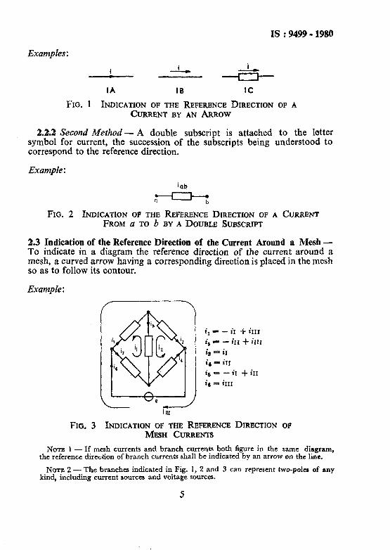
2.2.1 First Method - An arrow having a direction corresponding to the reference direction is placed on or beside the line representing the branch conductor, or beside the branch.
*Specification for letter symbols and signs used in electrical technology.
4
IS : 9499 - 1980
Examples :
IA I6 IC
FIG. 1 INDICATION OF THE REFERENCE DIRECTION OF A CURRENT BY AN ARROW
2.2.2 Second Method - A double subscript is attached to the letter symbol for current, the succession of the subscripts being understood to correspond to the reference direction.
Example :
iab
- G
FIG. 2 INDICATION OF THE REFERENCE DIRECTION OF A CURRENT FROM a TO b BY A DOUBLE SUBSCRIPT
2.3 Indication of the Reference Direction of the Current Around a Mesh - To indicate in a diagram the reference direction of the current around a mesh, a curved arrow having a corresponding direction is placed in the mesh so as to follow its contour.
Example :
&r - iI + iIIr
i, - - in -I- im is = ir
id - iIr
is = - iI $ ir1
is - im
FIG. 3 INDICATION OF TM? REFERENCE DIRECTION OF MESH CURRENTS
NOTE 1 - If mesh currents and branch currents both figure in the same diagram, the reference dire&on of branch currents shall be indicated by an arrow on the line.
NOTE 2 -The branches indicated in Fig. 1, 2 and 3 can represent two-paler of any kind, including current sources and voltage sources.
IS : 9499 - 1980
3. CONVENTIONS CONCERNING VOLTAGE (TENSION)
3.1 Polarity of a Voltage - The polarity of a voltage between two points is a term used to express which of the points has the higher potential.
3.2 Reference Polarity of a Voltage - The reference polarity of a voltage between two points is a polarity fixed arbitrarily for the two points. A voltage is considered as positive when its polarity corresponds to the reference polarity.
NOTB - ‘ Positive polarity * may be used instead of ‘ reference polarity ‘.
3.3 Reference Direction of a Voltage - The reference direction of a voltage between two points is a direction fixed arbitrarily from one point to the other. A voltage is considered as positive when the line-integral of the corresponding electric field intensity, taken between the two points in the reference direction, is positive.
NOTE - ‘ Positive direction ’ may be used instead of ‘ reference direction ‘.
3.4 Indication of the Sign Convention of a Voltage- To indicate in a diagram the sign convention of a voltage between two points, the three methods stated below are recommended.
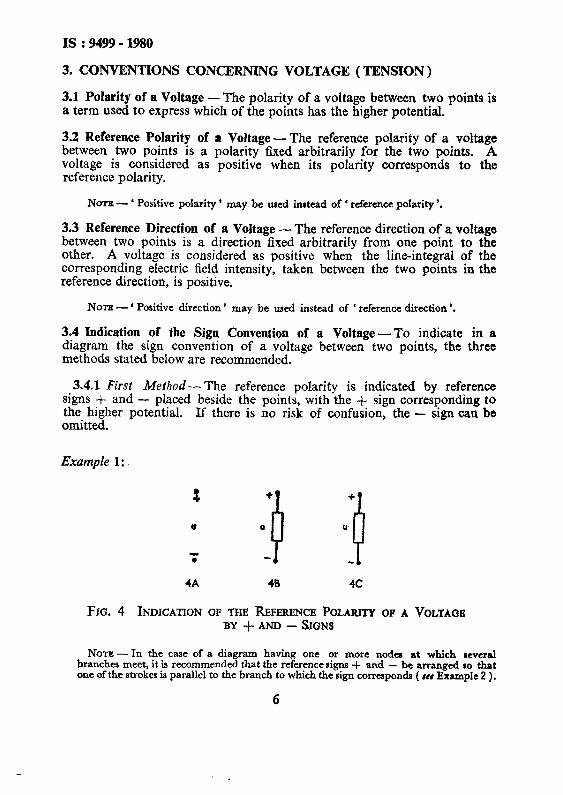
3.4.1 First Method- The reference polarity is indicated by reference signs + and - placed beside the points, with the + sign corresponding to the higher potential. omitted.
If there is no risk of confusion, the - sign can be
Example 1:
3 +
-, 4 0 0
.
+
u !I 4A 48 4c
FIG. 4 INDICATION OF THE REFERENCE POLARITY OF A VOLTAGE BY +.4m - SIGNS
NOTE - In the case of a diagram having one or more nodes at which several branches meet, it is recommended that the reference signs + and - be arranged so that one of the strokes is parallel to the branch to which the sign corresponds ( *et Example 2 ).
6
IS : 9499 - 1980
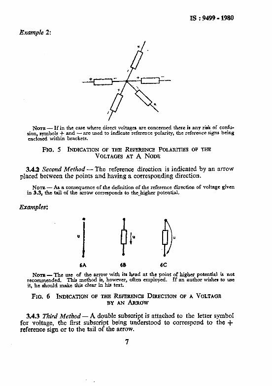
Example 2:
NOTE - If in the case where direct voltages are concerned there ir any risk of confu- sion, symbols + and -are used to indicate reference polarity, the reference signs being enclosed within brackets.
Fro. 5 INDICATION OF THE REFERENCE POLARITIES OF THE VOLTAGES AT A NODE
3.4.2 Second Method - The reference direction is indicated by an arrow pIaced between the points and having a corresponding direction.
NOTE - As a consequence of the definition of the reference direction of voltage given in 3.3, the tail of the arrow corresponds to the_,higher potential.
Examples:
6A 68 6C
NOTE - The use of the arrow with its head at the point of higher potential is not recommended. This method is, however, often employed. If an author wishes to use it, he should make this clear in his text.
FIG. 6 INDICATION OF THE REFZRENCE DIRECTION OF A VOLTAGE BY AN ARROW
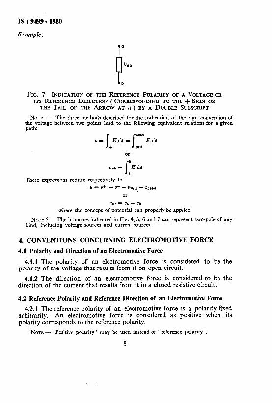
3.4.3 Third Method - A double subscript is attached to the letter symbol for voltage, the first subscript being understood to correspond to the + reference sign or to the tail of the arrow.
7
IS : 9499 - 1980
Example :
"ab
FIG. 7 INDICATION OF THE REFERENCE POLARITY OF A VOLTAGE OR ITS REFERENCE DIRECTION ( CORRESPONDING TO THE + SIGN OR
THE TAIL OF THE ARROW AT a) BY A DOUBLE SUBSCRIPT
NOTE 1 - The three methods described for the indication of the sign convention of the voltage between two points lead to the following equivalent relations for a given path:
These expressions reduce respectively to
u = V+ - U- - at,u - v&s‘,
or
where the concept of potential can properly be applied.
NOTE 2 - The branches indicated in Fig. 4, 5, 6 and 7 can represent two-pole of any kind, including voltage sources and current sources.
4. CONVENTIONS CONCERNING ELECTROMOTIVE FORCE
4.1 Polarity and Direction of an Electromotive Force
4.1.1 The polarity of an electromotive force is considered to be the polarity of the voltage that results from it on open circuit.
4.1.2 The direction of an electromotive force is considered to be the direction of the current that results from it in a closed resistive circuit.
4.2 Reference Polarity and Reference Direction of an Electromotive Force
4.2.1 The reference polarity of an electromotive force is a polarity fixed arbitrarily. An electromotive force is considered as positive when its polarity corresponds to the reference polarity.
NOTE - ‘ Positive polarity ’ may be used instead of ‘ reference polarity ‘,
8

IS I9499 - 1980
4.2.2 The reference direction of an electromotive force is a direction ffxed arbitrarily. An electromotive force is considered as positive when its direction corresponds to the reference direction.
NOTE- Positive direction ’ may be used instead of ‘ reference direction ‘.
4.3 Indication of the Sign Convention of an Electromotive Force-To indicate in a diagram the sign convention of an electromotive force between two points, the three methods stated below are recommended.
4.3.1 First Method- The reference polarity is indicated by reference signs + and - placed beside the points, with the + sign corresponding to the higher potential. If there is no risk of confusion, the - sign may be omitted.
Examples:
8A 88
FIG. 8 INDICATION OF THE REFERENCE POLARITY OF AN ELECTROMOTIVE FORCE BY + AND - SIGNS
4.3.2 Second Method -The reference direction is indicated by an arrow placed beside or within the symbol and having a corresponding direction.
NOTE - As a consequence of the definition of the direction of an electromotive force given in 4.1, the tail of the arrow corresponds to the lower potential.
Examples:
9A 98
FIG. 9 INDICATION OF THE REFERENCE DIRECTION OF AN ELECTROMOTIVE FORCE BY AN ARROW
4.3.3 Third Method - A double subscript is attached to the letter symbol E;ectromotive force, the first subscript being understood to correspond
- reference sign or to the tail of the arrow.
9

rs : 9499 ; 1980
Example :
‘bo
FIG. 10 INDICATION OF THE REFERENCE POLARITY OF AN ELECTROMOTIVE FORCE OR ITS REFERENCE DIRECTION
( CORRESPONDING TO THE - SIGN OR THE TAIL OF THE ARROW AT b) BY A DOUBLE SUBSCRIPT
NOTE 1 - The three methods described for the indication of the sign convention of the open-circuit electromotive force between two points lead to the following equivalent relations:
c==v+- lJ- * &e&d - %ll or
6b8 = 0. - ub where the concept of potential can properly be applied.
NOTE 2 -The graphical symbol for a voltage source is under consideration.
5. CONVENTIONS CONCERNING THE CHARGE OF A CAPACITOR
5.1 Reference Polarity of the Charge of a Capacitor-The reference polarity of the charge of a capacitor is a polarity fixed arbitrarily for the two electrodes of the capacitor. The charge of a capacitor is considered as positive when its polarity corresponds to the reference polarity.
NOTE-‘ Positive polarity ’ may be used instead of ’ reference polarity ‘.
5.2 Indication of the Reference Polarity of the Charge of a Capacitor- To indicate in a diagram the reference polarity of the charge of a capacitor, reference signs + and - are placed beside the two electrodes, the + sign corresponding to the positive charge. If there is no risk of confusion, the - sign may be omitted.
Examples :
J J-
7- T
IIA II9 FIG, 11 INDICATION OF THE REFERENCE POLARITY OF THB
CHARGE OF A CAPACITOR
10
IS : 9499 - 1980
6. CONVENTIONS CONCERNING MAGNETIC! FLUX
6.1 Reference Direction of a Magnetic Flux - The reference direction of the magnetic flux in a magnetic circuit is a direction fixed arbitrarily around the circuit. A magnetic flux is considered as positive when its direction corresponds to the reference direction.
NOTE - ‘ Positive direction ’ may be used instead of ‘ reference direction ‘.
6.2 Indication of the Reference Direction of a Magnetic Flux
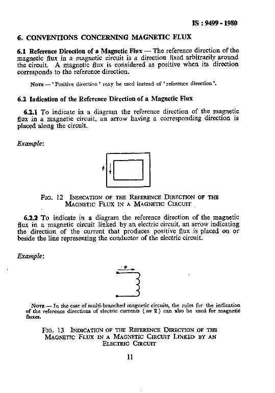
6.2.1 To indicate in a diagram the reference direction of the magnetic flux in a magnetic circuit, an arrow having a corresponding direction is placed along the circuit.
Example :
I.
FIG. 12 INDICA~ON OF THB REFERENCE DIRECTION OF THB MAGNETIC FLUX IN A MAGNETIC CIRCUIT
6.2.2 To indicate in a diagram the reference direction of the magnetic flux in a magnetic circuit linked by an electric circuit, an arrow indicating the direction of the current that produces positive flux is placed on or beside the line representing the conductor of the electric circuit.
Example :
NOTE - In the case of multi-branched magnetic circuits, the rules for the indication of the reference directions of electric currents (see 2 ) can also be used for magnetic fluxes.
FIG. 13 INDICATION OF THE REFERENCE DIRECTION OF THE MAGNETIC FLUX IN A MAGNETIC CIRCIJIT LINKED BY AN
ELECTRIC CIRCIJIT
11
IS : 9499 - 1980
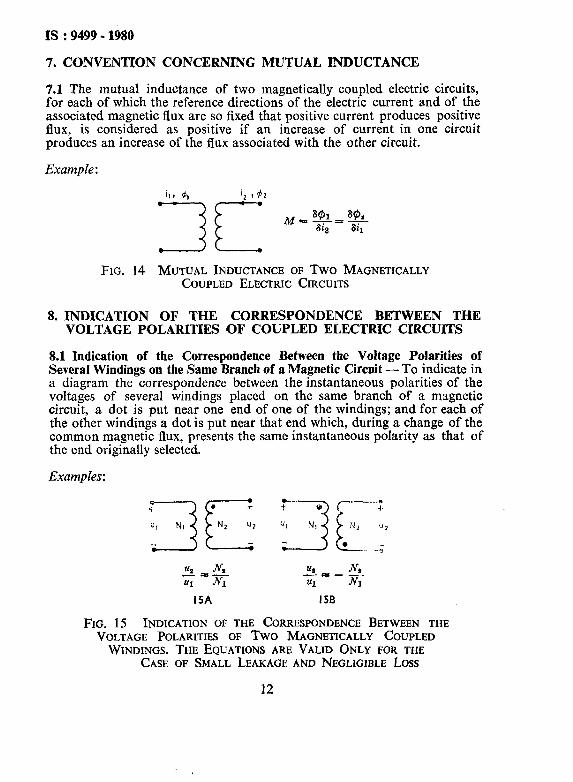
7. CONVENTION CONCERNING MUTUAL INDUCTANCE
7.1 The mutual inductance of two magnetically coupled electric circuits, for each of which the reference directions of the electric current and of the associated magnetic flux are so fixed that positive current produces positive flux, is considered as positive if an increase of current in one circuit produces an increase of the flux associated with the other circuit.
Example :
FIG. 14 MUTUAL INDUCTANCE OF Two MAGNETICALLY COUPLED ELECTRIC CIRCUITS
8. INDICATION OF THE CORRESPONDENCE BETWEEN THE VOLTAGE POLARITIES OF COUPLED ELECTRIC CIRCUITS
8.1 Indication of the Correspondence Between the Voltage Polarities of Severat Windings on the Same Branch of a Magnetic Circuit - To indicate in a diagram the correspondence between the instantaneous polarities of the voltages of several windings placed on the same branch of a magnetic circuit, a dot is put near one end of one of the windings; and for each of the other windings a dot is put near that end which, during a change of the common magnetic flux, presents the same instantaneous polarity as that of the end originally selected.
Examples:
9 “I) 1”’ 4 ; “~-jk _;
1, .N* v1,_, .N Ul K Ul sul
15A I5B
FIG. 15 INDICATION OF THE CORRESPONDENCE BETWEEN THE VOLTAGE POLARITIES OF Two MAGNETICALLY COUPLED
WINDINGS, THE EQUATIONS ARE VALID ONLY FOR THE CASE OF SMALL LEAKAGE AND NEGLIGIBLE Loss
12
IS : 9499 - 1980
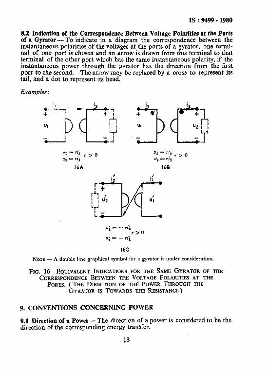
8.2 Indication of the Correspondence Between Voltage Polarities at the Parts of a Gyrator - To indicate in a diagram the correspondence between the instantaneous polarities of the voltages at the ports of a gyrator, one termi- nal of one port is chosen and an arrow is drawn from this terminal to that terminal of the other port which has the same instantaneous polarity, if the instantaneous power through the gyrator has the direction from the first port to the second. The arrow may be replaced by a cross to represent its tail, and a dot to represent its head.
Examples:
ui = - vi; r>O
u; = - ‘ii
16C
NOTE - A double line graphical symbol for a gyrator is under consideration.
FIG. 16 EQUIVALENT INDICATIONS FOR THE SAME GYRATOR OF THE CORRESPONDENCE BETWEEN THE VOLTAGE POLARITIES AT THE
PORTS. (THE DIRECTION OF THE POWER THROUGH THE GYRATOR IS TOWARDS TKE RESISTANCE)
9. CONVENTIONS CONCERNING POWER
9.1 Direction of a Power - The direction of a power is considered to be the direction of the corresponding energy transfer.
13
Is : 9499 - 1980
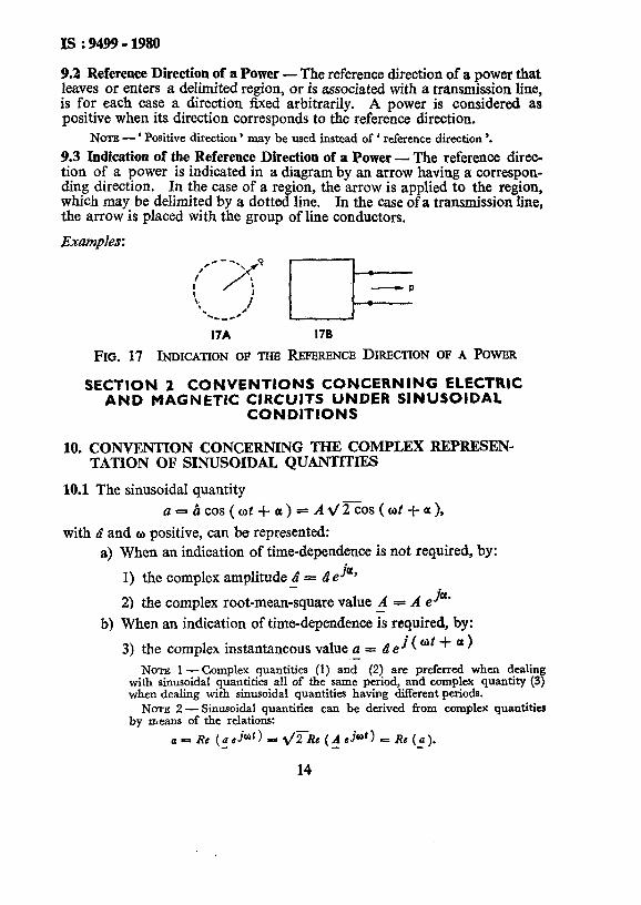
9.2 Reference Direction of a Power - The reference direction of a power that leaves or enters a delimited region, or is associated with a transmission line, is for each case a direction fixed arbitrarily. A power is considered as positive when its direction corresponds to the reference direction.
NOTE - ‘ Positive direction ’ may be used instead of ‘ reference direction ‘.
9.3 Indication of the Reference Direction of a Power - The reference direc- tion of a power is indicated in a diagram by an arrow having a correspon- ding direction. In the case of a region, the arrow is applied to the region, which may be delimited by a dotted line. In the case of a transmission line, the arrow is placed with the group of line conductors.
Examples: ,c--.
I’ \ 9
! /rl ! -P
\. % *C1_r*
it /
I7A 176
FIG. 17 INDICATION OF THE REFERENCE DIRECTION OF A POWER
SECTION 2 CONVENTIONS CONCERNING ELECTRIC AND MAGNETIC CIRCUITS UNDER SINUSOIDAL
CONDITIONS
10. CONVENTION CONCERNING THE COMPLEX REPRESEN- TATION OF SINUSOIDAL QUANTITIES
10.1 The sinusoidal quantity
ae=.~COS(Wt+Ob)=At/2oS(Wt+a),
with a^ and o positive, can be represented: a) When an indication of time-dependence is not required, by:
. 1) the complex amplitude 4 = a eJay
2) the complex root-mean-square value A = A G@ b) When an indication of time-dependence & required, by:
3) the complex instantaneous value a = d e j(wt+ a)
NOTE 1 - Complex quantities (1) and (2) are preferred when dealing with sinusoidal quantities all of the same period, and complex quantity (3) when dealing with sinusoidal quantities having different periods.
NOTE 2- Sinusoidal quantities can be derived from complex quantities by means of the relations:
14
11. CONVENTION CONCERNING TION OF OPERATORS
11.1 The operator that transforms the
a=-4cos(ot+a)=
THE COMPLEX REPRESENTA;
sinusoidal quantity
A ~27os(ot+a) _
into the sinusoidal quantity of the same period
Is :9499-1980
6=$cos(ot+f3)=B d.%os(ot+@) with &, 3 and w positive,. may be represented by the complex quantity:
C=Te 6 j(B-a) -d ej(b-a)
NOTE - The relations: i: B b
,c=* eC*l a A a
link the complex representation of the operator to the complex representation Of the sinusoidal quantities.
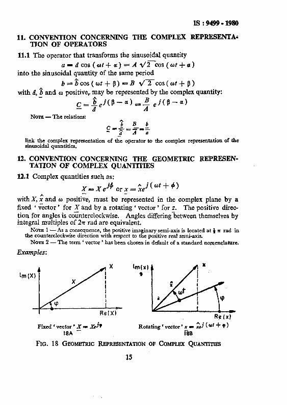
12. CONVENTION CONCERNING THE GEOMETRIC REPRESEN- TATION OF COMPLEX QUANTITIES
12.1 Complex quantities such as:
with X, x^ and o positive, must be represented in the complex plane by a fixed ‘ vector ’ for X and by a rotating ‘ vector ’ for z. The positive direc- tion for angles is co<nterclockwise. Angles differing-between themselves by integral multiples of 2n rad are equivalent.
NOTE 1 - As a consequence, the positive imaginary semi-axis is located at t x rad in the counterclockwise direction with respect to the positive real semi-axis.
NOTE 2 -The term ‘ vector ’ has been chosen in default of a standard nomenclature.
Examples:
Fixed I vector ’ X = XsjQ Rotating ( vector’ x I $j (at + Q ) IBA - i&B
FIG. 18 GEOMETRIC COMPLEX QUANTITIES
15

IS : 9499 6 1980
13. CONVJZNTION CONCERNING PHASE DIFFERENCE
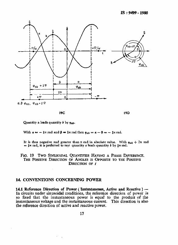
13.1 The phase difference +ab of the sinusoidal quantity
a=&CoS(~t+a)
with respect to the sinusoidal quantity of the same period
b=+os(wt+~)
with a, b^ and o positive, is expressed by the equation
(Pab = a - B
The phase difference qob represents the ( phase ) lead of a on b and the (phase ) lag of b on a.
NOTE - It is preferred to use the designation ‘ ( phase ) lead ( lag ) of a on b ’ only when the phase difference p&,, reduced to a value between - x rad and -!- x rad after the contingent subtraction or addition of an integral multiple of 2 x rad, is positive ( negative ) .
Quantity a leads quantity b by (Paa.
With a=& x rad and p = i z rad, then Tab = a’ - f3 = f x rad.
FIG. 19 Two SINIJSOIDAL QUANTITIES HAVING A PHASE DIFFERENCE. THE POSITIVE DIRECTION OF ANGLES IS OPPOSITE TO THE POLITIC
DIRECTION OF t - ( Co&)
16
IS : 9499 - 1980
19c
Quantity a leads quantity b by pabS
19D
Witha=- :nradandB=:XradthencPob=a-B=-~Xrad.
It is thus negative and greater than x rad in absolute value. With 9aa + 2x rad = :x rad, it is preferred to say: quantity a leads quantity b by ix rad.
FIG. 19 Two SINUSOIDAL QUANTITIES HAVING A PHASE DIFFERENCE. THE POSITIVFJ DIRECTION OF ANGLES IS OPPOSITE TO THE POSITIVX
DIRECTION OP i
14. CONVENTIONS CONCERNlNG POWER
14.1 Reference Direction of Power ( Instantaneous, Active and Reactive ) - In circuits under sinusoidal conditions, the reference direction of power is so tied that the instantaneous power is equal to the product of the instantaneous voltage and the instantaneous current. This direction is also the reference directioa Qf active and reactive power.
17

IS:9499-1980
Examples:
I _ i z
_ ” P-u/ P
! PIQ_ 1 U
20A 208
FIG. 20 REFERJINCB DIRECTXON OF POWER UNDER %NUSOlDAL CONDITIONS
Nontl - This convention leads to the following expression for active power: P=Re(UZ+)-Re(U+Z)= UZCOSQ, __ --
in which p represents the phase diEerence of u with respect to i.
Nora 2 - According to this convention a positive value of P indicates that the direc- tion of the active power corresponds to the reference direction of power.
14.2 Sign of Reactive Power -The positive sign is given to the reactive power absorbed by an inductor.
Nora - This convention leads to the following expression for reactive power: Q- Im (_V_l*) = - Im (?*I) - UZsinp,
in which rp represents the phase difference of u with respect to i.
14.3 Direction of Reactive Power - Reactive power is considered to have a direction which results from the convention that a capacitor produces it and an inductor absorbs it.
NOTE - According to this convention a positive value of Q indicates that the diiec- tion of the reactive power corresponds to the reference direction of power.
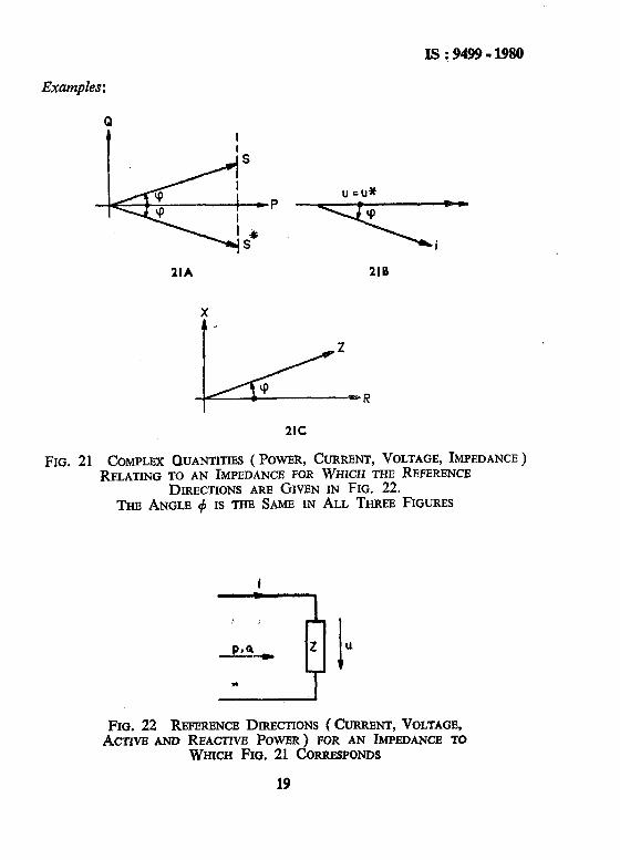
14.4 Complex Power Complex Apparent Power - The expression z==P+jQ=_Ul*
is called the complex power ( or complex apparent power ).
NOTE 1 -The geometric representation of this power should conform to 12.
NOTE 2 - In the case where, in dealm with operation at a given voltage, the direc- tion of the voltage ‘vector ’ is taken as t! e positive semi-axis of the active power the expression
S’ = P - jQ- YJ,
may be used so that the ( vectors ’ representing the current Z and the complex con- kgate power S* have the same direction.
18
Is :9499-1980
Examples :
1IA 21B
2lC
FIG. 21 COMPLEX QUANTITIES ( POWER, CURRENT, VOLTAGE, IMPEDANCE ) RELATING TO AN IMPEDANCE FOR WHICH THE REFERENCE
DIRECTIONS ARE GIVEN IN FIG. 22. Tq ANGLE + IS THE SAME IN ALL THREE FIGURES
FIG. 22 REFERENCE DIRECTIONS ( CURRENT, VOLTAGE, ACT~VE AND REACTIVE POWER) FOR AN IMPEDANCE TO
WHICH FIG. 21 CORRESPO~S
19

APPENDIX A
( Clauses 0.3.3 and 0.5 )
COMMENTARY
A-l. GENERAL
A-l.1 Circuit Concept - An electric circuit may be considered as an inter- connection of ‘ black boxes ‘. With the ‘ black box ’ concept only those properties are considered that may be observed from the outside; no account is taken of what goes on inside. The electric field external to ‘ black boxes ’ is considered to be irrotational, so that node potentials exist and Kirchhoff’s loop equations may be applied. The only quantities that may be observed external to a ‘ black box ’ are the currents at the terminals and the potential differences or voltages between terminal pairs. Such a ‘ black box ’ yields relations, determinable by measurement, between the currents and the voltages. The conventions are not concerned with these relations, although some of them appear in the examples.
Two ideal two-terminal ‘ black boxes ’ must be cited. They are: a) ( ideal) current source, in which the current is independent of the
terminal voltage; and b) ( ideal ) voltage source, in which the terminal voltage is indepen-
dent of the current.
A-l.2 Direction or Polarity and Sign - The second sentence of 2.1 speaks of the direction of a current and the sign of a current. The word ‘ current ’ in these two expressions has different meanings. The physical phenomenon of ‘ electric current ’ in a conductor has a direction. The physical quantity ‘ current ’ is a scalar and has a sign. Analogous observations may be made about voltage ( tension), electromotive force, charge of a capacitor, magne- tic flux, and power: the phenomena have direction or polarity, the quantities have sign. It has been deemed unnecessary in the conventions to make explicit the distinction between phenomena and quantities.
A-l.3 Reference Direction and Reference Polarity - Those clauses of the conventions which deal with reference directions and reference polarities contain two statements: a definition and a convention. In 2.1, for example, the reference direction of a current is first defined, and then follows a con- vention concerning its sign. The two statements could be combined by using the expression ‘ positive direction ’ instead of ‘ reference direction ‘. But such a method would not demonstrate clearly the fact that the clause contains both a definition and a convention. For current, which enjoys universal agreement as to the indication of its sign convention, this is un- important; but in other cases, for which such agreement is lacking, the distinction between definition and convention makes_ for clarity. For the
20
Is :9499;1980
sake of uniformity, however, the double statement is made for current as well as for the other quantities.
A-2. COMMENTARY ON CLAUSE 2: CONVENTIONS CONCERN- ING ELECTRIC CURRENT
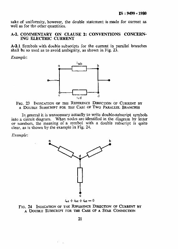
A-2.1 Symbols with double subscripts for the current in parallel branches shall be so used as to avoid ambiguity, as shown in Fig. 23,
Example :
FIG. 23 INDICATION OF THE REFERENCE DIRECTION OF CURRENT BY A DOUBLE SUBSCRIPT FOR THE CASE OF Two PARALLEL BRANCHES
In general it is unnecessary actually to write double-subscript symbols into a circuit diagram. When nodes are identified in the diagram by letter or numbers, the meaning of a symbol with a double subscript is quite clear, as is shown by the example in Fig. 24.
Example :
a b
C
i.d + ibd + iod - 0
FIG. 24 INDICATION OF THE REPERENCE DIRECTION OF CURRENT BY A DOUBLE SLJBSCRIPT FOR THE CASE OF A STAR CONNECTION
21
IS : 9499 - 1980
A-3. COMMENTARY ON CLAUSE 3: CONVENTIONS CONCERN- ING VOLTAGE ( TENSION )
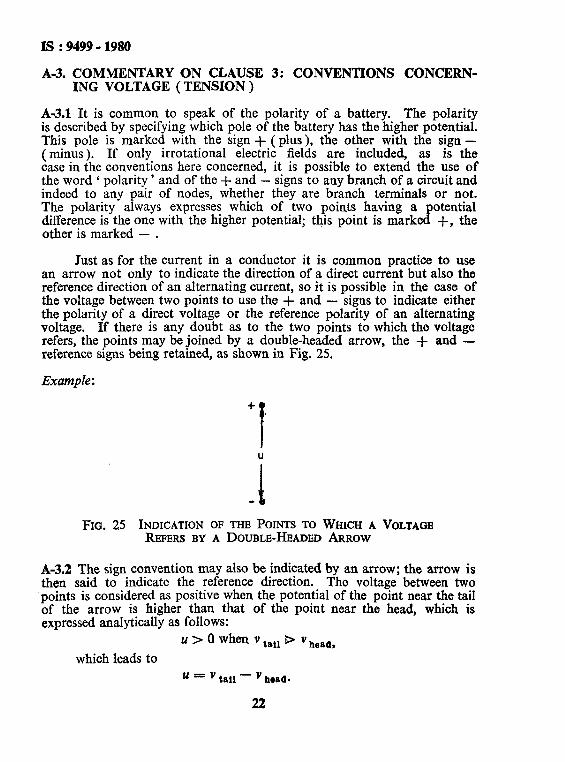
A-3.1 It is common to speak of the polarity of a battery. The polarity is described by specifying which pole of the battery has the higher potential. This pole is marked with the sign + ( plus), the other with the sign - (minus). If only irrotational electric fields are included, as is the case in the conventions here concerned, it is possible to extend the use of the word ‘ polarity ’ and of the + and - signs to any branch of a circuit and indeed to any pair of nodes, whether they are branch terminals or not. The polarity always expresses which of two points having a potential difference is the one with the higher potential; this point is marked +, the other is marked - .
Just as for the current in a conductor it is common practice to use an arrow not only to indicate the direction of a direct current but also the reference direction of an alternating current, so it is possible in the case of the voltage between two points to use the + and - signs to indicate either the polarity of a direct voltage or the reference polarity of an alternating voltage. If there is any doubt as to the two points to which the voltage refers, the points may be joined by a double-headed arrow, the + and - reference signs being retained, as shown in Fig. 25.
Example :
+
f
FIG. 25 INDICATION OF THE POINTS TO WHICH A VOLTAGE REFERS BY A DOUBLE-HEADED ARROW
A-3.2 The sign convention may also be indicated by an arrow; the arrow is then said to indicate the reference direction. The voltage between two points is considered as positive when the potential of the point near the tail of the arrow is higher than that of the point near the head, which is expressed analytically as follows:
u > 0 when v tsil B v hea,,,
which leads to
24 = v tat1 - v here.
22

15:9499-1980
This convention is justified by the correspondence of the reference direction of the voltage with the direction in which the line-integral of the electric field intensity is taken.
NOTE -To indicate the sign convention of a voltage, some authors use an MOW directed in a sense opposite to that recommended. For this,
u - Vll*oll - vton. These authors justify the method of associating the arrow head with positive polarity for both voltaae and electromotive force as being in the interests of uniformity, and also because draw&g an arrow in the direction of an increase of potential conforms with the common practice of drawing an arrow along a coordinate axis in the direction of increase of the coordinate.
This method of drawing arrows is not recommended.
A-3.3 Figure 26 gives an example ( the dual of that in Fig. 24) for double-subscript symbols not written into the circuit diagram.
Example :
hb f UbO + U#b= 0
FIG. 26 INDICATION OF THE SIGN CONVENTION OF VOLTAGE BY A DOUBLE SUBSCRIPT FOR THE CASE OF A DELTA CONNECTION
A-3.4 Examples of the association of the reference direction of current and the reference polarity or reference direction of voltage in a branch are given in Fig. 27.
Examples: J-a a i.
+
u 3 R
_
*
4 c u R
l
0
b R
.- I b
u = Ri u = Ri UBRi Ua, = R&a
27A 278 27C 27D
FIG. 27 ASSOCIATION OF THE REFERENCE INDICATIONS OF CURRENT AND VOLTAGE FOR A RJBI~TOR
23

IS : 9499 .i 1980 .
A-4. COMMENTARY ON CLAUSE 4: CONVENTIONS CONCERN- JNG ELECTROMOTIVE FORCE
A-4.1 The conventions retain the concept of electromotive force despite the fact that it is rejected by some schools of thought.
The relation between the method of indicating the reference direction of an electromotive force by an arrow and of indicating the reference polarity by + and - signs is the opposite of that recommended for voltage. Considering potentials, if an electromotive force and a voltage are both positive, the arrow for the electromotive force points in the direction of potential rise, while the arrow for the voltage points in the direction of potential fall.
The relation between the voltage u and the electromotive force e of a voltage source is shown by the examples in Fig. 28. Examples :
+ a+ efju e,(/)ju Q
e=U e=u e=u eba - uab
28A 288 28C 28D
FIG. 28 RELATIONS BETWEEN THE REFERENCE INDICATIONS OF ELECTROMOTIVE FORCE AND VOLTAGE OF A VOLTAGE SOURCE
A-5. COMMENTARY ON CLAUSE 5: CONVENTIONS CONCERN- ING THE CHARGE OF A CAPACITOR
A-5.1 Examples of the association for a capacitor of the reference direction of current, ‘the reference polarity of charge, and the reference polarity or reference direction of voltage are given in Fig. 29. The reference polarities should preferably be the same for both charge and voltage, as shown in Fig. 29A and 29B. Examples:
-L
f----, !f--JJ l + i T ~ C-T+J u! C--y
4 dq . 4 i= x,q== Cu ---pdt = ctr ‘-xsq - cu
29A 296 29C
FIG, 29 ASSOCIATION OF THE REFERENCE INDICATIONS OF CHARGE, CURRENT AND VOLTAGE FOR A CAPACITOR
24

IS : 9499 - 1980
Ad. COMMENTARY ON CLAUSE 6: CONVENTIONS CONCERN- ING MAGNETIC FLUX
A-6.1 Figure 30 gives examples of the association for a loss-free inductor of the reference direction of magnetic flux, the reference direction of current, and the reference polarity or reference direction of voltage. The reference directions of current and flux shouId preferably correspond as do the direc- tion of rotation and the direction of advance of a right-handed screw, as is shown in Fig. 30A and implied in Fig. 30B and 3OC.
Examples:
NcP’P Li 3QA 300
U= d@ 4 we dt u=T
Q = Li @--Li N= Number of turns 0 - flux per turn c$ = flux linkage
3oc 30D
FIG. 30 ASSOCIATION OF THE REFERENCE INDICATIONS OF MAGNETIC FLUX, CURRBNT AND VOLTAGE FOR AN INDUCTOR
A-7. COMMENTARY ON CLAUSE 7: CONVENTION CONCERNING MUTUAL INDUCTANCE
A-7.1 The condition that, for each electric circuit, the reference directions of the electric current and of the associated magnetic flux are so fixed that positive current produces positive ffux, is as much as to say that the energy supplied to the two circuits is given by the expression:
dW = iI d#l + it d+,
2s

Is : 9499 - 1980
The sign of the mutual inductance remains indefinite so long as the reference directions of current and flux for the two circuits have not been fixed. If the reference directions of il and &, or of ir and &, are reversed, so also will be the sign of the mutual inductance.
It would be possible to take M as always positive, and write the circuit equations with been chosen.
- M when 6+1/6i,, was negative; but this convention has not The convention adopted has the advantage of leading to the
same set of equations whatever the sign of 8+JSi,, so that the equations remain unchanged even when 8&/8i, varies continuously through a change of sign, a condition that may occur in a variable mutual inductor.
An example of the relations between voltages and currents in two magnetically coupled loss-free electric circuits is given in Fig. 31, and the associated equations. The example shows that, to determine the sign of the mutual inductance, instead of fixing for each circuit the reference direc- tions of the current and of the associated magnetic flux, it is equally possible to fix for each circuit the reference direction of current and the reference polarity or reference direction of voltage. If they are so fixed that the power supplied to the circuits may be written:
then the relations are:
P = il u1 + is u,,
i, i2 + ;ZjMr u 2
-4 Fro. 31 MUTUAL INDUCTANCE OF Two MAGNETICALLY COUPLED
ELECTRIC CIRCUITS
A-8. COMMENTARY ON CLAUSE 8: INDICATION OF THE COR; RESPONDENCE BETWEEN THE VOLTAGE POLARITIES OF COUPLED ELECTRIC CIRCUITS
A-8.1 The correspondence between voltage polarities due to a change of the common magnetic flux may be determined by applying current to one only of the windings, leaving the other windings open.
26
IS : 9499 - 1980
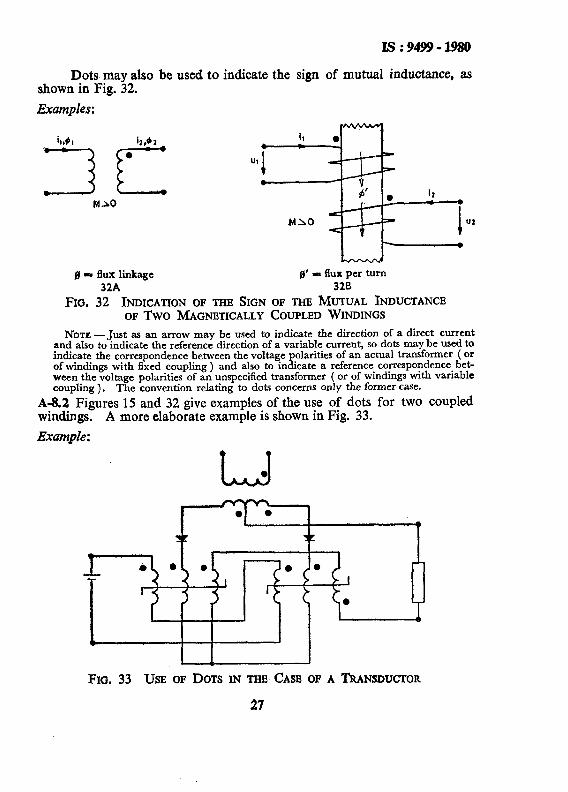
Dots may also be used to indicate the sign of mutual inductance, as shown in Fig. 32.
Examples :
UX
.
fl= flux linkage g’ = flux per turn 32A 320
FIG. 32 INDICATION OF THE SIGN OF THE MUTUAL INDUCTANCE OF Two MAGNETICALLY COUPLED WINDINGS
NOTE -Just as an arrow may be used to indicate the direction of a direct current and also to indicate the reference direction of a variable current, so dots may be used to indicate the correspondence between the voltage polarities of an actual transformer ( or of windings with fixed coupling ) and also to indicate a reference correspondence bet- ween the voltage polarities of an unspecified transformer ( or of windings with variable coupling). The convention relating to dots concerns only the former case.
A-8.2 Figures 15 and 32 give examples of the use of dots for two coupled windings. A more elaborate example is shown in Fig. 33.
Example:
FIG. 33 USE OF DOTS IN THE CASE OF A TRANSDUCTOR
27
IS : 9499 - 1980
A-S.3 An ( ideal) gyrator ( see 8.2 ) is linear, loss-free, anti-reciprocal two-port defined by the equations given with Fig. 16 (A gyrator may be approximately realised by a metadyne and, in microwave technology, by a waveguide containing ferrite in a permanent magnetic field ). The direction of the power through a gyrator is that of the energy transfer when the second port is connected to a resistance R. Then, for Fig. 16A and 16B:
from which
Ul -= u2
+> 0,
and for Fig. 16C:
from which
ui -= Ui
-+o.
NOTE - A remark similar to the preceding one, concerning the use of dots to indi- cate a reference correspondence, applies to the use of an arrow, or of a cross and a dot, to indicate the reference correspondence between the voltage polarities at the ports of an unspecified gyrator.
A-9. COMMENTARY ON CLAUSE 9: CONVENTIONS CONCERN- ING POWER
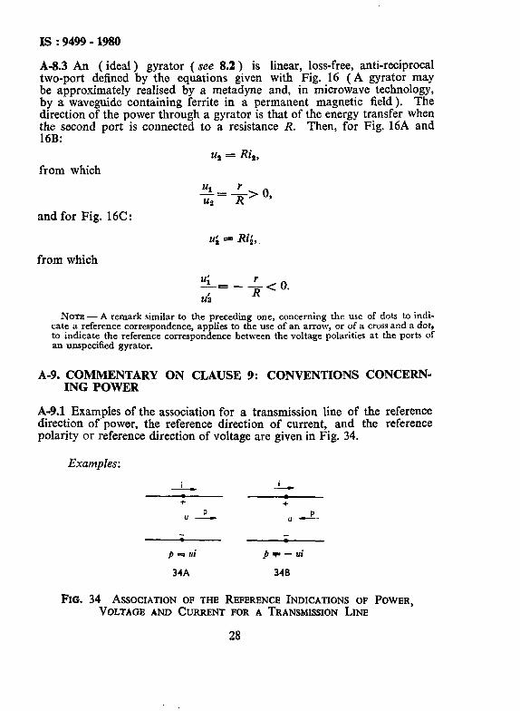
A-9.1 Examples of the association for a transmission line of the reference direction of’power, the reference direction of current, and the reference polarity or reference direction of voltage are given in Fig. 34.
Examples:
_L, j_
+ +
Up_ “L
p 4 ui pY=-ui
34A 340
FIG. 34 ASSOCIATION OF THE REFERENCE INDICATIONS OF POWER, VOLTAGE AND CURRENT FOR A TRANSMISSION LINE
28
Is : 9499 - 1980
A-10. COMMENTARY ON CLAUSE 10: CONVENTION CONCERN- ING THE COMPLEX REPRESENTATION OF SINUSOIDAL QUANTITIES
A-10.1 The condition that w is positive is imposed to obtain a univalued complex amplitude. This condition expresses that the rule of 10 may be applied to find the complex amplitude only if the coefficient of t in the argument of the cosine is positive. It may be shown as follows that if this condition is not fulfilled there will be an ambiguity. Given the equality
a^ cos ( wt-+-a ) = a” Cos ( ( - 0 ) t - a ),
then without the condition specified the rule of 10 may be applied to both members of the equality. The first member yields the complex amplitude
Be - j ‘, the second y’ lelds a” e - J ‘.
The condition that a^ is positive is necessary in order that a” shall be the modulus and a the argument of the complex amplitude.
NOTE - The condition for fis not needed to obtain a univalued complex amplitude. Given the quality.
~cos(ot+a)=(-~~jos~OI+;=+X)}
then without the condition the complex amplitude may be written
;cj,and also (-1) c j(a+ x).
These two expressions are identically qua1 and therefore represent the complex ampli- tude in a univalued manner.
A-11. COMMENTARY ON CLAUSE 11: CONVENTION CONCERN- ING THE COMPLEX REPRESENTATION OF OPERATORS
A-11.1 No commentary is necessary.
A-12. COMMENTARY ON CLAUSE 12: CONVENTION CONCERN- ING THE GEOMETRIC REPRESENTATION OF COMPLEX QUANTITIES
A-12.1 In Fig. 18 the angles are marked by arcs with arrowheads which serve to endow an angle with a sign. For this purpose the concept of the angle of a ‘ vector ’ n with respect to another b is introduced and defined by the rotation that-turns b into the position oT a. The arc indicates the zone swept out in the rotation, the arrowhead %dicates the direction of rotation. When the latter is counterclockwise, the angle is considered as positive. In Fig. 35 the angle ‘p is positive, the angle (p--2x rad is negative. In Fig. 1 SA the argument 4 is represented by the angle of d vector ’ X with respect to the positive real semi-axis.
29

IS :9499-1980
Example:
FIG. 35 GEOMETRIC REPRESENTATION OF AN ANGLE so AS TO INDICATE ITS SIGN
A-13. COMMENTARY ON CLAUSE 13: CONVENTION CONCERN- ING PHASE DIFFERENCE
A-13.1 The term ‘ phase displacement ’ ( between two sinusoidal quantities ) is defined as the difference between the phases of these quantities at a given instant. This concept is used in the conventions as a quantity that may be positive or negative. For such a quantity the term ‘ phase difference ’ seems to be more apt, and has been preferred to the term ‘ phase displacement ‘.
Tn order to attribute a sign to the phase difference (P&. of one sinusoidal quantity a with respect to another 4, of the same period, and of which the phases are ot+a and wt+@ respectrvely, it is necessary to chose between the definition
qoa = a - B shown in Fig. 19, and the contrary definition in which the letters a and p are interchanged. Preference has been given to that displayed in the equation because its use is more common. If the second sinusoidal quantity is taken as reference, then
p 6 o; ‘Pab = a
The condition that j and $ are positive is necessary in order that the phase difference shall be defined within an integral multiple of 2n rad. The sign of a opposite to that of b would result in a change in the phase difference by> rad.
-
The term ‘ ( phase ) lead ( lag ) ’ may represent a quantity that may be positive or negative; but it may also be used as a designation, as is mentioned in the Note.
Considerations similar to those concerning arcs with arrowheads, given in 12 of the commentary, apply to straight lines with arrowheads in Fig. 19A and 19C. The angle Tab is represented by the displacement that shifts b into the position of a. Consequentlp, the positive direction of angles is opposite to the positive direction of t. Thus the arrows that indicate the angles u and @ in Fig. 19A and 19C have tails on the same line, just as do the curved arrows of Fig. 19B, 19D that correspond to them.
30
A-14.
Is:94994980
COMMENTARY ON CLAUSE 14; CONVENTIONS CONCERN- ING POWER
A-14.1 In 14.4 the complex power ( or complex apparent power ) is defined by the equation
_S=P+iQ that is as the sum of its real and imaginary parts, as is the custom for complex numbers in mathematics. The outcome of this definition is that the argument cp of the complex power S is the same as the argument of the corresponding complex impedance Z, G shown in Fig. 21A and ZIG!. In the Note 2 to 14.4 it is observed th<t the use of the quantity S* = P- jQ may be advantageous in certain cases.
The expressions for the active power P and reactive power Q are derived as follows, ‘ active power ’ is synonymous with ‘ mean power ‘, which may be represented by
p=p
From 14.1 the sign of p is that of ui, whence
P ==z
It may be deduced from
ZJ = 4rRe (_VejWf)
that iif = Re ( UZ*).
These relations Iead to P= Re( UZ*). -
Reactive power is the product of the voltage and the reactive current, whence it may be deduced that
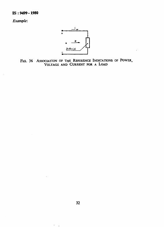
IQI-lImP*)l - According to 14.2, the reactive power absorbed by an inductive load
is positive. The situation is illustrated by Fig. 36, the sign conventions of which satisfy 14.1; the direction of the arrow for p, pointing towards the load, indicates that the power absorbed by the load is being considered. It may be deduced from the figure that
lm( UZ*))-Zm[(R+jX)c*]=XZ2, - which shows for an inductive load, that is for positive X, that Im ( UZ* ) is positive. These relations lead to
-
Q=Im(gZ*)
31
IS : 9499 - 1980
FIG. 36 ASSOCIATION OF THE REFERENCE INDICATIONS OF POWER, VOLTAGE AND CURRENT FOR A LOAD
32