IS1690S-255 DSP APPLICATION NOTE INTRODUCTION TO...
32
IS1690S-255 DSP APPLICATION NOTE – INTRODUCTION TO DSP TOOL AND AEC TUNING GUIDE (V1.1) - Multi-Speaker (Phone) Application
Transcript of IS1690S-255 DSP APPLICATION NOTE INTRODUCTION TO...
IS1690S-255 DSP APPLICATION NOTE –
INTRODUCTION TO DSP TOOL AND AEC
TUNING GUIDE (V1.1)
- Multi-Speaker (Phone) Application
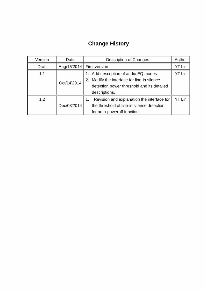
Change History
Version Date Description of Changes Author
Draft Aug/15’2014 First version YT Lin
1.1
Oct/14’2014
1. Add description of audio EQ modes
2. Modify the interface for line-in silence
detection power threshold and its detailed
descriptions.
YT Lin
1.2
Dec/03’2014
1. Revision and explanation the interface for
the threshold of line-in silence detection
for auto-poweroff function.
YT Lin
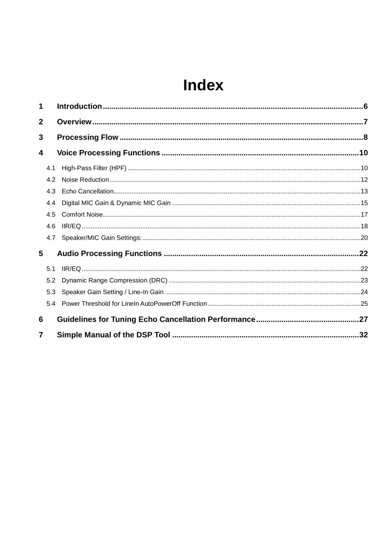
Index
1 Introduction ............................................................................................................................ 6
2 Overview ................................................................................................................................. 7
3 Processing Flow .................................................................................................................... 8
4 Voice Processing Functions .............................................................................................. 10
4.1 High-Pass Filter (HPF) ................................................................................................................................... 10
4.2 Noise Reduction ............................................................................................................................................. 12
4.3 Echo Cancellation........................................................................................................................................... 13
4.4 Digital MIC Gain & Dynamic MIC Gain .......................................................................................................... 15
4.5 Comfort Noise................................................................................................................................................. 17
4.6 IIR/EQ ............................................................................................................................................................. 18
4.7 Speaker/MIC Gain Settings: ........................................................................................................................... 20
5 Audio Processing Functions ............................................................................................. 22
5.1 IIR/EQ ............................................................................................................................................................. 22
5.2 Dynamic Range Compression (DRC) ............................................................................................................ 23
5.3 Speaker Gain Setting / Line-In Gain .............................................................................................................. 24
5.4 Power Threshold for LineIn AutoPowerOff Function ...................................................................................... 25
6 Guidelines for Tuning Echo Cancellation Performance ................................................. 27
7 Simple Manual of the DSP Tool ......................................................................................... 32

Figure
Figure 1: The block diagram of the processing flow for the speakerphone applications for
(a) speech and (b) audio signal processing. ............................................................................ 8
Figure 2: Main function page. ............................................................................................................. 10
Figure 3: High-pass filter parameters. .............................................................................................. 11
Figure 4: NR parameters. ..................................................................................................................... 13
Figure 5: Parameter tuning interface for echo cancellation performance. ............................ 14
Figure 6: Tuning interface for MIC gains and comfort noise. .................................................... 17
Figure 7: DSP tool interface for configuring the EQ for voice processing. ........................... 19
Figure 8: An example of configuring the EQ/IIR functions. ........................................................ 20
Figure 9: Illustrating the function of the Q factor.......................................................................... 20
Figure 10: DSP tool interface of configuring the speaker gain in the SCO mode. ............... 21
Figure 11: DSP tool interface for configuring the IIR/EQ in the audio (or SBC) mode. ...... 23
Figure 12: Mapping function of DRC. ............................................................................................... 24
Figure 13: DSP tool interface of configuring the speaker gain in the audio (or SBC) mode.
............................................................................................................................................................. 25
Figure 14: An illustration of the AEC tuning flow. ........................................................................ 27
Figure 15: Illustration of the CVSD slope overload effect, where x(t) and xQ(n) are denoted
as the original signal and CVSD encoded/decoded signal, respectively. ...................... 28
Figure 16: An example of the frequency shaping for signal at the speaker path. ............... 29
Figure 17: The cover page of the DSP tool. .................................................................................... 32

Table
Table 1: Summary of module functionalities .................................................................................... 7
Table 2: EEPROM addresses for enabling HPF at the SCO speaker path. ............................ 10
Table 3: EEPROM addresses for enabling HPF at the SCO MIC path. .................................... 11
Table 4: EEPROM addresses for configuring HPF function ...................................................... 11
Table 5: EEPROM addresses for enabling NR at the SCO speaker path. ............................... 12
Table 6: EEPROM addresses for enabling NR at the SCO MIC path. ...................................... 12
Table 7: EEPROM addresses for configuring NR function ......................................................... 13
Table 8: EEPROM addresses for enabling AEC function. .......................................................... 15
Table 9: Configuring the AEC paramters......................................................................................... 15
Table 10: EEPROM addresses for enabling the digital boost gain at the SCO MIC path. .. 16
Table 11: EEPROM addresses for enabling the dynamic MIC control at the SCO MIC path
............................................................................................................................................................. 16
Table 12: EEPROM addresses for enabling the comfort noise at the SCO MIC path .......... 18
Table 13: EEPROM addresses for enabling the EQ/IIR functions. ........................................... 19
Table 14: EEPROM addresses for MIC and Speaker Gains ........................................................ 21
Table 15: EEPROM addresses for enabling the IIR/EQ in the audio (or SBC) mode. .......... 22
Table 16: EEPROM addresses for enabling the auto poweroff function for LineIn silence
detection. .......................................................................................................................................... 26
1 Introduction
ISSC IS1690S-255 chips provide high-performance noise reduction and acoustic echo
cancellation with advanced signal processing techniques. Sophisticated voice and audio
enhancement functions, including filtering, equalizations and intelligent MIC control, are also
provided. Combining with these state-of-the-art processing and these voice and audio functions
working together, a simple tuning flow for tuning the AEC and NR accommodated for different
applications are given for easy product development as well.
This document will also give the tutorial about how to tune each of the parameters that are
provided in the DSP tool step by step to allow the system designer to finetune DSP features for
particular requirements. The DSP tool provides the visual interface to adjust the parameters for
all provided voice and audio signal processing functions.

2 Overview
ISSC IS1690S -255 chips feature high-performance signal processing that can provide the
excellent voice/audio user experience. Included fundamental and optional modules are
Stationary Noise Reduction (NR), Acoustic Echo Cancellation (AEC), Audio Equalization (EQ),
High-Pass Filter (HPF) and the Finite Impulse Response (FIR) filters. In addition, AEC function is
only provided at the microphone (Uplink) path in the SCO link connection.
The functionality of each these modules are summarized in Table I.
Table 1: Summary of module functionalities
Module Functionality
AEC Cancel the acoustic echo coupled into the microphone for the loud speaker output.
NR Suppress the stationary ambient noise to enhance the voice signal quality.
EQ
Provides the 5-band EQs for both voice and audio applications in order to compensate
imperfect frequency response of the adopted microphone or speaker. Defaulted audio effects
are also provided to enhance the user experience.
FIR
Provides the linear filtering capability to shape the frequency responses of the microphone or
speaker such as to remove the static 60Hz board noises, etc.
HPF Provides a low-latency IIR-structured low-pass filter to filter out unwanted low frequency band
for both MIC/SPK paths.

3 Processing Flow
Before introducing the signal processing flow, some abbreviations and terminology are defined
in advance for avoiding the further confusion. The path, that BT device receives bitstream and
pass to DSP for decoding process, can be called as the downlink, downstream, far-end and
speaker paths in this document. On contrary, the path, that BT device transmit the bitstream that
is encoded by the DSP processor, is called as uplink, upstream, near-end and MIC paths.
Far- End
NRIIR/EQ DAC
Audio
Amp
ADCFIRAECNear-End
NR/AES
Half-Duplex
Suppression
FIR
MIC Gain
Compensation
Digital Mic
Gain
Additive
Background
Noise
IIR/EQ
CVSD/A-
Law/u-Law
Decoders
CVSD/A-
Law/u-Law
Encoders
DSP
ISSC BT Chip
8051
Processor/
BT
RF/Base-
band
Processor
(a)
DACAudio
AmpSBC
Decoders
DSP
ISSC BT Chip
8051
Processor/BT
RF/Base-
band
Processor
IIR / EQDynamic
Range
Compression
(b)
Figure 1: The block diagram of the processing flow for the speakerphone applications for (a)
speech and (b) audio signal processing.
Figure 1 shows the block diagram of DSP processing flow for speakerphone applications. In
these chips, the DSP module is focused on speech and audio processing. The embedded ADC
and DAC provide high-fidelity data conversions with 85dB and 94dB SNRs, respectively. The
8051 processor and the BT RF/modem processor are dealing with the medium access control
and the wireless data transiting. For the speakerphone application, the external audio amplifiers

are usually needed to boost the signal to the desired volume.

4 Voice Processing Functions
In the main page, one can select the IC version to set up corresponding DSP configurations.
Checkboxes for “Speakerphone” and “Speaker” are also available where if “Speaker” mode is
selected, AEC/NR functions are automatically disabled.
Figure 2: Main function page.
4.1 High-Pass Filter (HPF)
Function:
7 selectable cutoff frequencies are available for HPF, which is a low-latency IIR filter. Its
purpose is to filter out unwanted low-frequency signal, such as board noise, current noise and
wind noise, etc. It is a trade-off between speech signal quality and the noise reduction level.
EERPOM settings:
To enable the far-end HPF module
Table 2: EEPROM addresses for enabling HPF at the SCO speaker path.
Addr Bit 5 at 0x0300
Value 0x1
To enable the near-end NR module
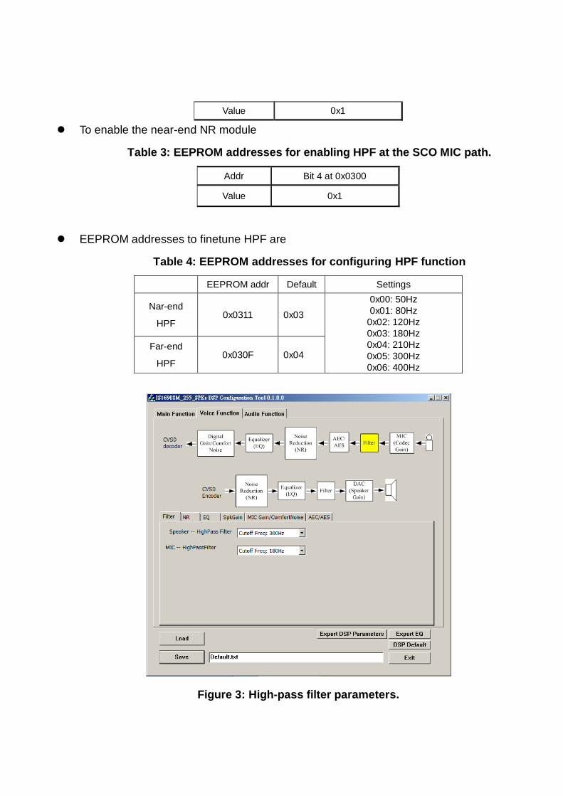
Table 3: EEPROM addresses for enabling HPF at the SCO MIC path.
Addr Bit 4 at 0x0300
Value 0x1
EEPROM addresses to finetune HPF are
Table 4: EEPROM addresses for configuring HPF function
EEPROM addr Default Settings
Nar-end
HPF 0x0311 0x03
0x00: 50Hz
0x01: 80Hz
0x02: 120Hz
0x03: 180Hz
0x04: 210Hz
0x05: 300Hz
0x06: 400Hz
Far-end
HPF 0x030F 0x04
Figure 3: High-pass filter parameters.
4.2 Noise Reduction
The noise reduction (NR) function suppresses stationary noises present in the
far-end/downstream and near-end/up-stream signals. With iSSC’s proprietary intelligent voice
activity detection (VAD), the NR module can effectively suppress the unwated noise while
maintaining satisfactory quality for the speech communication. This function allows both
near-end and far-end talkers to experience benefits.
Function:
Two selectable parameters for NR configurations shown in Figure 4 are suppression levels
for low-frequency (<1000Hz) and high-frequency (from 1000Hz to 4000Hz). The tunable range
for both speaker and MIC paths are from 0dB to 21dB. However, in the DSP tool, only the
low-frequency NR suppression level is provided while high-frequency suppression levels are
determined empirically based on field-test results.
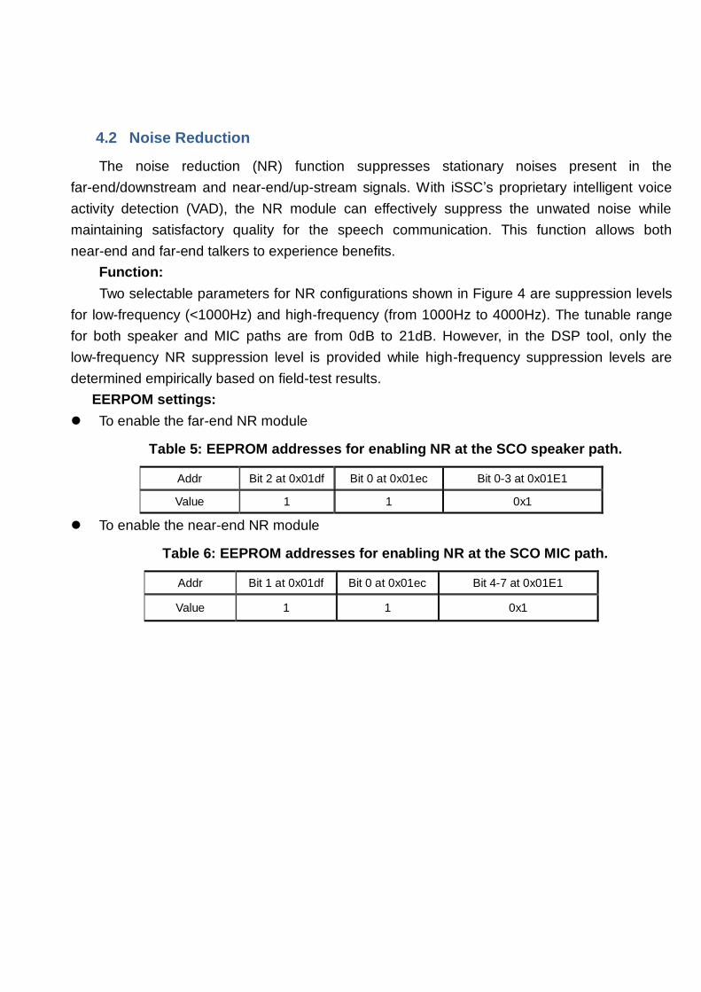
EERPOM settings:
To enable the far-end NR module
Table 5: EEPROM addresses for enabling NR at the SCO speaker path.
Addr Bit 2 at 0x01df Bit 0 at 0x01ec Bit 0-3 at 0x01E1
Value 1 1 0x1
To enable the near-end NR module
Table 6: EEPROM addresses for enabling NR at the SCO MIC path.
Addr Bit 1 at 0x01df Bit 0 at 0x01ec Bit 4-7 at 0x01E1
Value 1 1 0x1
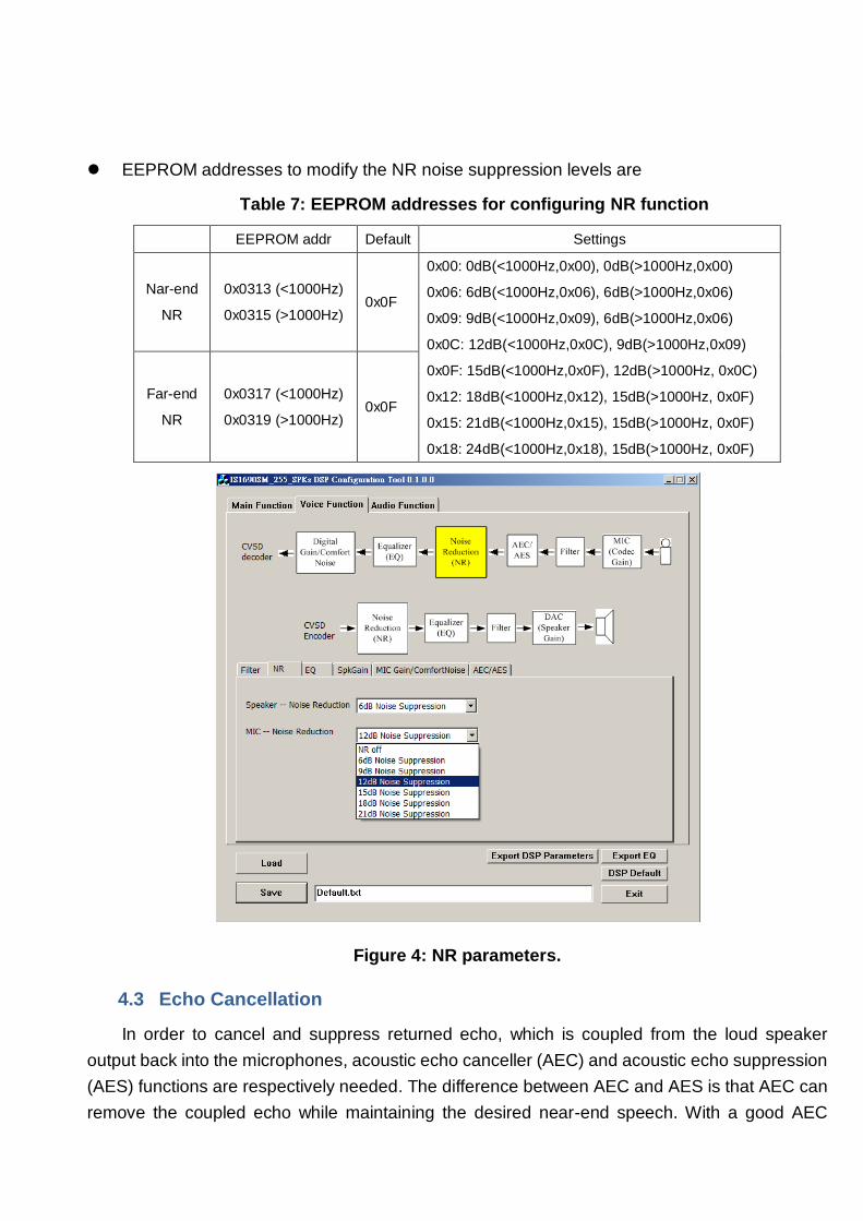
EEPROM addresses to modify the NR noise suppression levels are
Table 7: EEPROM addresses for configuring NR function
EEPROM addr Default Settings
Nar-end
NR
0x0313 (<1000Hz)
0x0315 (>1000Hz) 0x0F
0x00: 0dB(<1000Hz,0x00), 0dB(>1000Hz,0x00)
0x06: 6dB(<1000Hz,0x06), 6dB(>1000Hz,0x06)
0x09: 9dB(<1000Hz,0x09), 6dB(>1000Hz,0x06)
0x0C: 12dB(<1000Hz,0x0C), 9dB(>1000Hz,0x09)
0x0F: 15dB(<1000Hz,0x0F), 12dB(>1000Hz, 0x0C)
0x12: 18dB(<1000Hz,0x12), 15dB(>1000Hz, 0x0F)
0x15: 21dB(<1000Hz,0x15), 15dB(>1000Hz, 0x0F)
0x18: 24dB(<1000Hz,0x18), 15dB(>1000Hz, 0x0F)
Far-end
NR
0x0317 (<1000Hz)
0x0319 (>1000Hz) 0x0F
Figure 4: NR parameters.
4.3 Echo Cancellation
In order to cancel and suppress returned echo, which is coupled from the loud speaker
output back into the microphones, acoustic echo canceller (AEC) and acoustic echo suppression
(AES) functions are respectively needed. The difference between AEC and AES is that AEC can
remove the coupled echo while maintaining the desired near-end speech. With a good AEC
capability, the full-duplex speech communication can be achieved easily. However, unfortunately,
nonlinear echo, caused by ID housing, analog circuit and the echo environment cannot be
canceled out by AEC. Hence, what AES does is to intelligently suppress the full-band input
signal with the assist of AEC information. By doing so, the desired speech quality would be
degraded if the nonlinear echo dominates the MIC input signal.
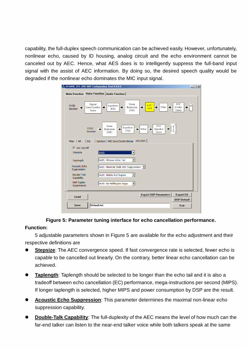
Figure 5: Parameter tuning interface for echo cancellation performance.
Function:
5 adjustable parameters shown in Figure 5 are available for the echo adjustment and their
respective definitions are
Stepsize: The AEC convergence speed. If fast convergence rate is selected, fewer echo is
capable to be cancelled out linearly. On the contrary, better linear echo cancellation can be
achieved.
Taplength: Taplength should be selected to be longer than the echo tail and it is also a
tradeoff between echo cancellation (EC) performance, mega-instructions per second (MIPS).
If longer taplength is selected, higher MIPS and power consumption by DSP are the result.
Acoustic Echo Suppression: This parameter determines the maximal non-linear echo
suppression capability.
Double-Talk Capability: The full-duplexity of the AEC means the level of how much can the
far-end talker can listen to the near-end talker voice while both talkers speak at the same
time. Basically, this parameter maps to a threshold that controls the AES to nonlinearly
suppress the echo. If this parameter is set to be more favorable to half-duplexity, the
double-talk capability degraded more. On the contrary, the residual echo becomes more
perceivable at the far-end side.
Half-Duplex Suppression: The parameter is to suppress echo based on the far-end voice
power level. If the power level of the far-end voice exceeds a certain threshold, the
half-duplex suppression is triggered to suppress the near-end signal regardless of near-end
voice activity. This is only fine-tuned when the AEC and AES both can’t effectively suppress
the echo.
EERPOM settings:
To enable the AEC, one needs to set as follows:
Table 8: EEPROM addresses for enabling AEC function.
Addr Bit 0 at 0x01df Bit 4 at 0x01ec Bit 0-2 at 0x01E2
Value 1 1 0x01
The AEC’s parameters and their corresponding meaning are
Table 9: Configuring the AEC paramters
Parameters Address Note Default Value
Stepsize 0x031F 0x01: Fastest AEC convergence ~
0x06: Slowest AEC convergence 0x02
TapLength 0x0321 0x01: 8msec Echo Tail ~
0x0A: 80msec Echo Tail 0x0A
Double-Talk Capability 0x0325 0x00: More Full Duplex
0x0F: Least Full Duplex 0x0C
Acoustic Echo
Suppression 0x0323
0x00: 24dB AES Suppression ~
0x06 :60dB AES Suppression 0x04
Half-Duplex Suppression 0x0326 0x70: No Half-Duplex Suppression
0x01: 42dB Suppresion 0x20
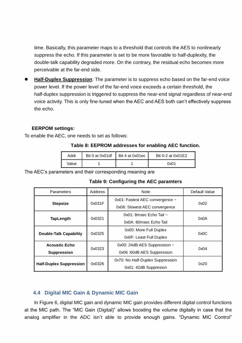
4.4 Digital MIC Gain & Dynamic MIC Gain
In Figure 6, digital MIC gain and dynamic MIC gain provides different digital control functions
at the MIC path. The “MIC Gain (Digital)” allows boosting the volume digitally in case that the
analog amplifier in the ADC isn’t able to provide enough gains. “Dynamic MIC Control”

automatically detects if the MIC input is saturated or not and decreases the analog MIC gain
while increasing the digital gain to maintain the same MIC’s output volume. As shown in Figure
1(a), the digital boost part of the dynamic MIC Control is placed at the end of all digital signal
processing modules.
Notice:
Digital MIC gain: by adjusting the digital MIC gain, the potential issue is to amplify the
AES-suppressed echo.
Dynamic MIC Control Range: The potential issue to allow higher dynamic MIC range is
that the signal to noise ratio of the MIC input is also degraded and the PCB grounding noise
would also be boosted by the post digital gain compensation.
EERPOM settings:
To enable the Digital MIC gain, one needs to configure the following addresses:
Table 10: EEPROM addresses for enabling the digital boost gain at the SCO MIC path.
Addr Bit 5 at 0x0303 0x030D
Value 1
0x00: 0dB Digital Boost
0x01: 6dB Digital Boost
0x02: 12dB Digital Boost
0x03: 18dB Digital Boost
0x04: 24dB Digital Boost
To enable the Dynamic MIC gain, one needs to configure as shown in Table 11.
Table 11: EEPROM addresses for enabling the dynamic MIC control at the SCO MIC path
EEPROM Address Bit 5 at 0x0303 MIC Gain (0x00C5) Dynamic Range (0x030B)
Values
1 (Must be
asserted to
enable this
function)
MIC Gain >= 0x0C
0x00:0dB dynamic MIC range
0x40:6dB dynamic MIC range
0x80:12dB dynamic MIC range
0xC0:18dB dynamic MIC range
0x0C> MIC Gain >=
0x08
0x00:0dB dynamic MIC range
0x40:6dB dynamic MIC range
0x80:12dB dynamic MIC range
0x08> MIC Gain >= 0x04 0x00:0dB dynamic MIC range
0x40:6dB dynamic MIC range
0x04> MIC Gain 0x00:0dB dynamic MIC range
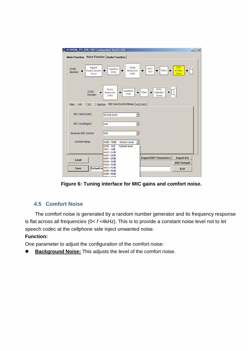
Figure 6: Tuning interface for MIC gains and comfort noise.
4.5 Comfort Noise
The comfort noise is generated by a random number generator and its frequency response
is flat across all frequencies (0< f <4kHz). This is to provide a constant noise level not to let
speech codec at the cellphone side inject unwanted noise.
Function:
One parameter to adjust the configuration of the comfort noise:
Background Noise: This adjusts the level of the comfort noise.

EERPOM settings:
Table 12: EEPROM addresses for enabling the comfort noise at the SCO MIC path
EEPROM Address Values
Bit 5 at 0x0303 1 (Must be asserted to enable this function)
0x0329
0x00: 0dBc Highest Comfort Noise level
0x01: -6dBc Comfort Noise level
0x02: -12dBc Comfort Noise level
0x03: -18dBc Comfort Noise level
0x04: -24dBc Comfort Noise level
0x05: -30dBc Comfort Noise level
0x06: -36dBc Comfort Noise level
0x07: -42dBc Comfort Noise level
0x08: -48dBc Comfort Noise level
0x09: -54dBc Comfort Noise level
0x0A: -60dBc Comfort Noise level
0x0B: -66dBc Comfort Noise level
0x0C: -72dBc Comfort Noise level
0x0D: -78dBc Comfort Noise level
(Recommended)
0x0E: -84dBc Comfort Noise level
0x0F: -90dBc Comfort Noise level
4.6 IIR/EQ
The IIR/EQ provides the flexibility for compensating the imperfect frequency responses of
the selected MIC and speaker. This function provides a 5-band customized filter for both MIC
and speaker paths.
Figure 7 shows an example about how to select the customized equalizer’s coefficients.
One can also assign Custom1 to MIC path and Custom 2 to SPK paths. Afterwards, one can
click into the “Custom EQ 1” and then a window shown in Figure 6 is poped out. In Figure 8, one
can type in the desired frequencies and the gain/attenuations. The “Q” columns are to configure
the cutoff frequencies of each band. An example is shown in Figure 9, the smaller the value of “Q”
is, and the wider the bandpass cutoff frequency is. Buttons, “M+” and “MR”, function as the
calculator’s “M+” and “MR”. The major purpose for these two buttons is to record the frequency
responses for easy analysis comparison. If one wants to store the frequency response that just
being designed, click “Save” in Figure 6 and system would automatically store the current EQ’s
configuration into a file. Also, if want to restore a frequency response that have been previously
designed, click “Load Response” to restore the EQ configurations.
The column “Stage” configures how many bands of 1-order IIR filter are used. The fewer the
“Stages” are, the lower the MIPS as well as the power consumption is.
EERPOM settings:
In order to enable the EQ for voice application, one needs to configure the following bits:
Table 13: EEPROM addresses for enabling the EQ/IIR functions.
Bit3
0x1EC
Bit6 of
0x1DF
Bit5 of
0x1DF 0x1E8 0x1E9
Bit 2 of
0x1E1
Bit 6 of
0x1E1
MIC path 1 1 No need 0x07 0xFF 1 No need
Speaker
path 1 No need 1 0x07 0xFF No need
1
The coefficients of the Custom1 and Custom2 are stored from 0x0356 to 0x03FD.
Figure 7: DSP tool interface for configuring the EQ for voice processing.

Figure 8: An example of configuring the EQ/IIR functions.
Figure 9: Illustrating the function of the Q factor.
4.7 Speaker/MIC Gain Settings:
The number of speaker gain level and MIC gain are configured in the DSP tool. Figure 8
shows that there are three different number of speaker gain levels are selectable based on
particular requirements. Once the number of the speaker gain level is determined, one can
choose the corresponding gain for each level.
The difference between each MIC gain level is roughly between 2.7dB ~ 3.4dB per step.
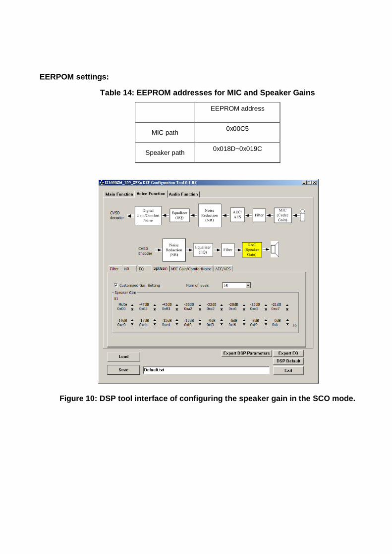
EERPOM settings:
Table 14: EEPROM addresses for MIC and Speaker Gains
EEPROM address
MIC path 0x00C5
Speaker path 0x018D~0x019C
Figure 10: DSP tool interface of configuring the speaker gain in the SCO mode.

5 Audio Processing Functions
5.1 IIR/EQ
The system diagram of the audio signal processing is shown in Figure 1(b). In addition to the
SBC decoder, only one IIR/EQ are allowed to process to audio signal. Figure 8 shows the
configuration of the IIR/EQ for the audio function. In the column “EQ Mask Selection,” one can
select the adjustable special audio sound effect. Except the option “Custom EQ,” one can use
an external button to select different sound effects. The procedure to configure “Custom EQ 2” is
also identical to the IIR/EQ introduced in section 4.5.
For IS169x chip series used for multi-speaker applications, two EQ modes are also available
for normal and twin modes, which are:
Normal mode:
Normal mode indicates the Bluetooth device is working standalone connecting with
Bluetooth host device. Then, Normal mode for EQ finetuning is available to fit in their desired
frequency responses in such mode.
Twin mode:
Twin mode indicates that the Bluetooth device is connected with Bluetooth host device as
well as another Bluetooth device at the same time. In this mode, another EQ coefficient can be
applied.
One example of such applications is a Bluetooth sound-bar and its subwoofer. When
sound-bar and subwoofer respectively serve as master and slave speakers in Twin modes, EQ
filter of subwoofer can be configured as a low-pass filter to filter out high frequency signal while
EQ of soundbar can probably be configured as a high-pass filter.
However, if only soundbar speaker is working standalone without subwoofer, the soundbar
speaker can be applied by the EQ coefficients configured in Normal mode.
EERPOM settings:
In order to enable the EQ for voice application, one needs to configure the following bits:
Table 15: EEPROM addresses for enabling the IIR/EQ in the audio (or SBC) mode.
Addr Bit3 0x1EC Bit5 of 0x1E0 0x1E8 0x1E9
Values 1 1 0x07 0xFF

Figure 11: DSP tool interface for configuring the IIR/EQ in the audio (or SBC) mode.
5.2 Dynamic Range Compression (DRC)
Figure 12 illustrates the general concept of DRC which transform the input signal nonlinearly
to its output. The behavior of DRC is controlled by three tunable parameters which are “DRC
Threshold”, “DRC Compression Ratio” and “DRC Gain”. By referring to
DRC Threshold:
This parameter corresponds to the compression threshold in Figure 12. This parameter
constrains that sound level to which the make-up gain is applied.
DRC Compression Ratio (CR):
CR is a compression ratio which compresses the average sound level, exceeding “DRC
Threshold”, of the audio signal. However, if CR is closer and closer to 0, more distortion is easily
generated due to the DRC compression.
DRC Gain:
DRC gain denotes the maximal gain applying to audio signal whose average power is

between silence threshold and the compression knee. This parameter can boost soft music
signal to an audible level especially in a noisy environment.
Output
Input
0dB-10dB-20dB-30dB-40dB-50dB-60dB
-60dB
-50dB
-40dB
-30dB
-20dB
-10dB
0dB
Compression
Threshold
Make-Up
Gain
Compression
Ratio (CR)
CR = 1/2
CR = 1/3
CR = 1/4
Silence
Threshold
Figure 12: Mapping function of DRC.
5.3 Speaker Gain Setting / Line-In Gain
Similar to the speaker setting for voice application, the number of speaker gain level is also
selectable. The selection procedure can refer to section 4.7.
In addition, line-in loopback function is to play audio signal from the external audio playback
devices. The “Initial Line-In Gain” is to configure the initial line-in gain to amplify the external
signal source and playback to the speakers. “MaxGainLevel” and “MinGainLevel” denote the
maximal and minimum gain levels in the line-in mode, respectively. The gain table of lineIn mode
shares the same gain table as in the A2DP mode (SBC music playback mode).
Figure 13 shows that four numbers of speaker gain level are selectable.

Figure 13: DSP tool interface of configuring the speaker gain in the audio (or SBC) mode.
5.4 Power Threshold for LineIn AutoPowerOff Function
Line-In Silence detection function enables the system to detect whether the line-in signal is in
silence mode or not. Note that this function also requires co-designs with extra external
PCB circuit and enabling the auto-power-off setting in the UI tool. (Please refer to the
application note for the PCB design guideline).
The concept of line-in silence detection function is to calculate the average power of the line-in
signal. This function reports to the system controller about the silence status by monitoring
whether the average power exceeds a defined threshold or not.
EERPOM settings:
In the EEPROM setting, we have measured the silence level and prestored in the DSP tool as
shown in Figure

Table 16: EEPROM addresses for silence power threshold of Linein auto poweroff
function.
EEPROM Addr Bit0~6, 0x339
Enabled
0x08 (-24dBov)
0x09 (-27dBov)
0x0A (-30dBov)
0x0B (-33dBov)
0x0C (-36dBov)
0x0D (-39dBov)
0x0E (-42dBov)
0x0F (-45dBov)
0x10 (-48dBov)
0x11 (-51dBov)
0x12 (-54dBov)
0x13 (-57dBov)
:
:
0x1F (-93dBov)
Disabled 0x20

6 Guidelines for Tuning Echo Cancellation Performance
This section introduces a guideline to fine-tune the echo cancellation performance. There
are usually three requirements, which are high MIC volume, echo-free and double-talk (DT)
performance, for the EC tuning. These three requirements contradict with each other. For
example, if requiring high volume at the MIC path, echo would be amplifies as well and need to
tune some parameters to make echo inaudible which would result in worse DT performance. As
shown in Figure 14, step 1 ~ step 5 are basically handling these whole speakerphone/carkit echo
issues.
Download
8051+DSP
Patch code
Set desired
Max SPK
gain
Set desired
MIC gain
(The Sound
level that
Remote listeners
feel comfortable
with)
Use the
DSP tool to
generate the
defaulted
parameters
Enable the
Equalizer
(IIR) at the
speaker
(This is to shape
the frequency
response of the
response )
Testing
single-talk
echo
Tuning
“Double-Talk Capability”(from 0x02 à 0x0F)
“Half-Duplex Suppression”(from 0x20 à 0x01)
Testing
Double-talk
echo
Yes
No Echo
Tuning
“Double-Talk Capability”
(from 0x0F à 0x02)
“Half-Duplex Suppression”
(from 0x20 à 0x70)
End
This is an
optional stepStep 2 Step 3
Step 4
Step 5
Step 1
Figure 14: An illustration of the AEC tuning flow.

The details of these steps are explained as follows.
Step 1: First of all, download all of the merged patch code which consists of the settings, for
user interface (UI), 8051 and DSP, and merged patch code for 8051 and DSP parts. Some DSP
functions may be implemented in the patch code such that download the latest patch code can
get in sync with this document.
Step 2: Before tuning the AEC performance, the desired maximal speaker output level must be
determined. More specifically, the recommended speaker output volume should be at least 95dB
SPL (sound pressure level) and 100dB SPL for indoor speakerphone and car-kit applications,
respectively. Note that the target speaker output volume needs to be determined in the
beginning based on the required specification.
Step 3: The principle to adjust the MIC gain to a suitable value. It is not necessarily good to set
the MIC to its maximal level because the slope overlaod effect, as shown in Figure 15, caused by
the CVSD codec itself would naturally suppress the high frequency parts and makes it look like a
low pass filter. This effect would distort the near-end speech and make it not as clear as the
softer MIC gain levels.
(See the reference link for more information of the CVSD slope overlaod effect:
http://www.datasheetcatalog.org/datasheet/CML/mXxyzvw.pdf )
Figure 15: Illustration of the CVSD slope overload effect, where x(t) and xQ(n) are denoted
as the original signal and CVSD encoded/decoded signal, respectively.
Step 4: This is an optional step. The purpose of this step is to shape the frequency response of
the speaker output by lowering the low frequency (<1 kHz) and enhancing the high frequency
parts (1 kHz to 3 kHz). By doing so, the echo reverberation within the speakerphone/ car kit
housing can be reduced such that the linearity of the echo coupled to the MIC input can be better.
The echo linearity is highly associated with the AEC performance. An example is given in Figure
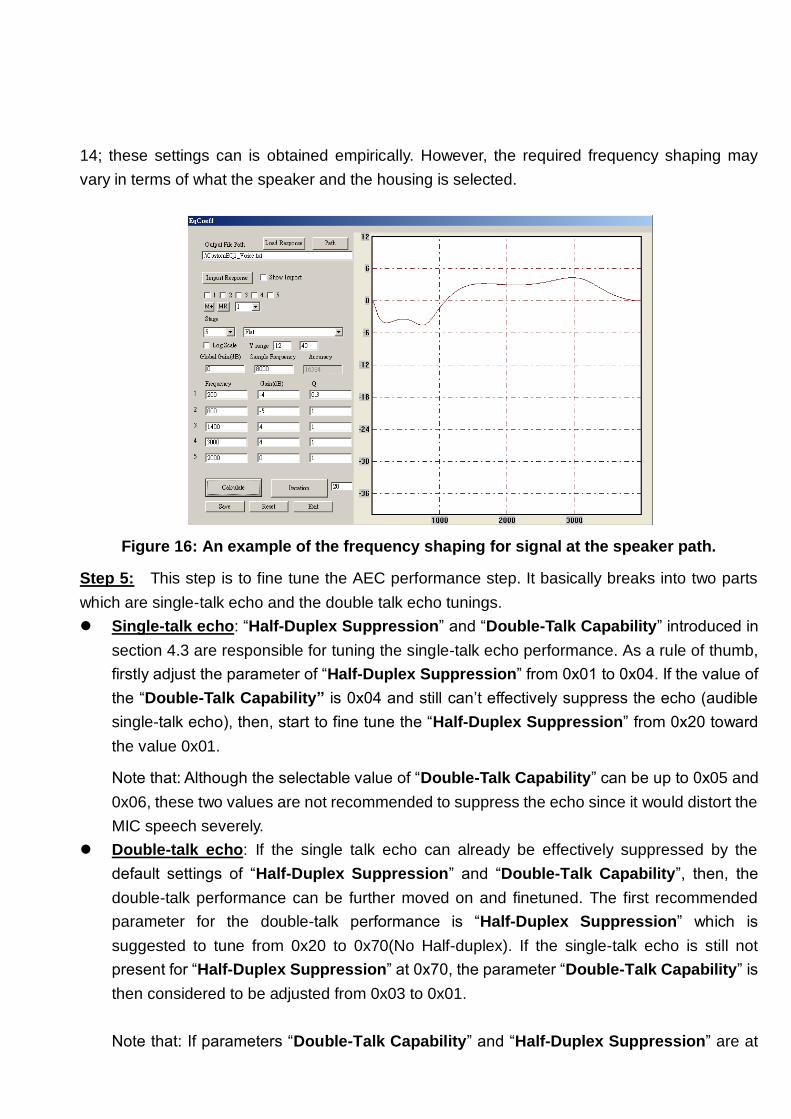
14; these settings can is obtained empirically. However, the required frequency shaping may
vary in terms of what the speaker and the housing is selected.
Figure 16: An example of the frequency shaping for signal at the speaker path.
Step 5: This step is to fine tune the AEC performance step. It basically breaks into two parts
which are single-talk echo and the double talk echo tunings.
Single-talk echo: “Half-Duplex Suppression” and “Double-Talk Capability” introduced in
section 4.3 are responsible for tuning the single-talk echo performance. As a rule of thumb,
firstly adjust the parameter of “Half-Duplex Suppression” from 0x01 to 0x04. If the value of
the “Double-Talk Capability” is 0x04 and still can’t effectively suppress the echo (audible
single-talk echo), then, start to fine tune the “Half-Duplex Suppression” from 0x20 toward
the value 0x01.
Note that: Although the selectable value of “Double-Talk Capability” can be up to 0x05 and
0x06, these two values are not recommended to suppress the echo since it would distort the
MIC speech severely.
Double-talk echo: If the single talk echo can already be effectively suppressed by the
default settings of “Half-Duplex Suppression” and “Double-Talk Capability”, then, the
double-talk performance can be further moved on and finetuned. The first recommended
parameter for the double-talk performance is “Half-Duplex Suppression” which is
suggested to tune from 0x20 to 0x70(No Half-duplex). If the single-talk echo is still not
present for “Half-Duplex Suppression” at 0x70, the parameter “Double-Talk Capability” is
then considered to be adjusted from 0x03 to 0x01.
Note that: If parameters “Double-Talk Capability” and “Half-Duplex Suppression” are at

0x01 and 0x70, the double-talk performance is still not so good.

Three possible measures to improve the double-talk performance:
1. Increase the AEC MIC gain: Go back to step 3 to increase the MIC gain. Because AES
and AEC would suppress echo as well as the double-talk near-end speech, the
double-talk performance can be improved if the near-end speech energy is raised up
such that the near-end speech may become audible while no single-talk echo is present.
2. Adjust the frequency shaping shown in Figure 14: If the speaker output level is very loud
and echo-to-speech ratio at the MIC input is too high, one way to improve this is to
further suppress the low-frequency part of the speaker output. As a result, the
echo-to-speech ration at the low frequency parts of the MIC input is further reduced and
could have better double-talk performance.
3. Use the handsets supporting the full-duplex AEC: Some handsets, such as Samsung
Gallaxy II, and HTC Incredible etc., don’t support the full-duplex speech communication
while connecting with the BT handfree devices. In this way, one can’t obtain satisfactory
full-duplex performance while using these handsets.
4. Allow only one channel output (Assuming for the stereo speakerphone case): If the
distance between the MIC and one of the speaker channels are very close (<4cm), the
AEC tuning for the full-duplexity becomes very difficult. One simple way is to turn off the
closer speaker channel output and only allow the other speaker to output such that the
full-duplexity can be much easier to be achieved. The User Interface (UI) can configure
the number of the desired speaker channel outputs.
7 Simple Manual of the DSP Tool
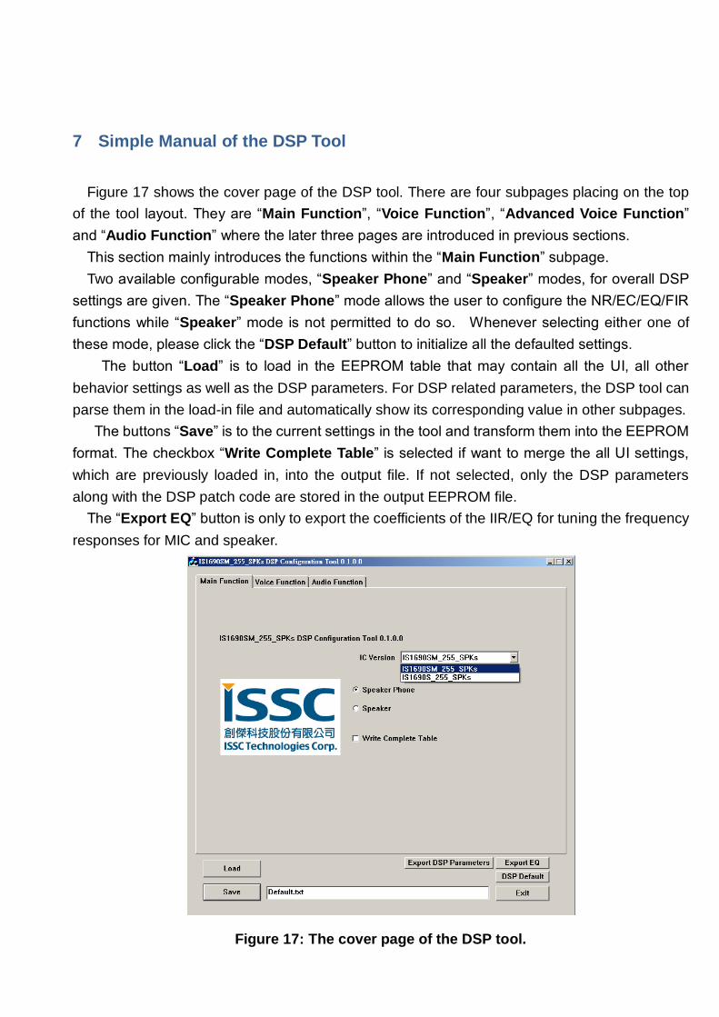
Figure 17 shows the cover page of the DSP tool. There are four subpages placing on the top
of the tool layout. They are “Main Function”, “Voice Function”, “Advanced Voice Function”
and “Audio Function” where the later three pages are introduced in previous sections.
This section mainly introduces the functions within the “Main Function” subpage.
Two available configurable modes, “Speaker Phone” and “Speaker” modes, for overall DSP
settings are given. The “Speaker Phone” mode allows the user to configure the NR/EC/EQ/FIR
functions while “Speaker” mode is not permitted to do so. Whenever selecting either one of
these mode, please click the “DSP Default” button to initialize all the defaulted settings.
The button “Load” is to load in the EEPROM table that may contain all the UI, all other
behavior settings as well as the DSP parameters. For DSP related parameters, the DSP tool can
parse them in the load-in file and automatically show its corresponding value in other subpages.
The buttons “Save” is to the current settings in the tool and transform them into the EEPROM
format. The checkbox “Write Complete Table” is selected if want to merge the all UI settings,
which are previously loaded in, into the output file. If not selected, only the DSP parameters
along with the DSP patch code are stored in the output EEPROM file.
The “Export EQ” button is only to export the coefficients of the IIR/EQ for tuning the frequency
responses for MIC and speaker.
Figure 17: The cover page of the DSP tool.