IS Series Actuator Operating Manual - iai-robot.co.jp€¦ · IAI Corporation IS Series Actuator...
136
IAI C o r p o r a t i o n IS Series Actuator Operating Manual Fourteenth Edition ISB, ISPB IS Cast SSPA
Transcript of IS Series Actuator Operating Manual - iai-robot.co.jp€¦ · IAI Corporation IS Series Actuator...

IAI Corporation
IS Series Actuator Operating Manual
Fourteenth Edition
ISB, ISPB IS Cast SSPA


Please Read Before Use Thank you for purchasing our product. This Operating Manual explains the handling methods, structure and maintenance of this product, among others, providing the information you need to know to use the product safely. Before using the product, be sure to read this manual and fully understand the contents explained herein to ensure safe use of the product. The DVD that comes with the product contains operation manuals for IAI products. When using the product, refer to the necessary portions of the applicable operation manual by printing them out or displaying them on a PC. After reading the Operating Manual, keep it in a convenient place so that whoever is handling this product can reference it quickly when necessary.
[Important] • This Operating Manual is original. • The product cannot be operated in any way unless expressly specified in this Operating Manual. IAI shall
assume no responsibility for the outcome of any operation not specified herein. • Information contained in this Operating Manual is subject to change without notice for the purpose of product
improvement. • If you have any question or comment regarding the content of this manual, please contact the IAI sales office
near you. • Using or copying all or part of this Operating Manual without permission is prohibited. • The company names, names of products and trademarks of each company shown in the sentences are
registered trademarks.


Table of Contents Safety Guide ............................................................................................................................ 1
Caution in Handling ................................................................................................................. 8
Names of the Parts .................................................................................................................. 9
1. Checking the Product ...................................................................................................... 11 1.1 Components ........................................................................................................................................ 11 1.2 Related Operation Manuals for Each Controller Supported by This Product...................................... 11 1.3 How to Read the Model Nameplate.....................................................................................................13 1.4 How to Read the Model Numbe ..........................................................................................................13
2. Specification .................................................................................................................... 14 2.1 Maximum Speed ..................................................................................................................................14 2.2 Acceleration/Deceleration, Payload Capacity and Rated Thrust.........................................................18 2.3 Driving System/Position Detector ........................................................................................................24 2.4 Positioning Precision ...........................................................................................................................26 2.5 Allowable Moment of the Actuator .......................................................................................................26
3. Life................................................................................................................................... 29 3.1 How to Calculate Operation Life ...........................................................................................................29 3.2 Operation Life........................................................................................................................................30
4. Installation and Storage/Preservation Environment ......................................................... 31 4.1 Installation Environment ......................................................................................................................31 4.2 Storage/Preservation Environment......................................................................................................31
5. Transportation ................................................................................................................. 32 5.1 Handling a Single Axis .........................................................................................................................32
5.1.1 Handling the Packed Unit ....................................................................................................32 5.1.2 Handling an Actuator after Unpacking .................................................................................32
5.2 Handling an Cartesian Robot (ICS) .....................................................................................................33 5.2.1 Handling a Package.............................................................................................................33 5.2.2 Handling an Actuator after Unpacking .................................................................................33
5.3 Handling an Actuator Assembled to a Mechanical System .................................................................34 6. Installation ....................................................................................................................... 35
6.1 Installation Orientations .......................................................................................................................35 6.2 Installing the Actuator ..........................................................................................................................37
6.2.1 Installation Method...............................................................................................................37 6.2.2 Precision of the Installation Surface ....................................................................................41
6.3 Installing the Load on the Slider ..........................................................................................................43 6.4 Using T-slots ........................................................................................................................................47
7. Connecting the Controller................................................................................................ 48 7.1 Wiring...................................................................................................................................................48
8. Operating Conditions....................................................................................................... 51 8.1 Duty Ratio during Continuous Operation.............................................................................................51
9. Setting the Home Position ............................................................................................... 52
9.1 Home Return .......................................................................................................................................52 9.2 Factory-set Home Position ..................................................................................................................52 9.3 Changing the Home Direction .............................................................................................................52 9.4 How to Use the Homing Mark Stickers ................................................................................................53 9.5 Fine-tuning the Home Position ............................................................................................................54
9.5.1 X-SEL and SSEL Controllers ...............................................................................................54 9.5.2 ECON, SCON and MSCON Controllers ..............................................................................57
9.6 Absolute Reset Method (Absolute Specification) ................................................................................60 10. Options ............................................................................................................................ 61
10.1 Brake....................................................................................................................................................61 10.2 Creep Sensor.......................................................................................................................................61 10.3 Limit Switch..........................................................................................................................................62 10.4 Reversed-home Specification..............................................................................................................63 10.5 Cable Exit Direction .............................................................................................................................63 10.6 Guide with Ball Retention Mechanism.................................................................................................63 10.7 Master Axis/Slave Axis Specification for Synchronized Operation ......................................................64 10.8 High-Precision Straightness Specification ...........................................................................................65 10.9 Rust prevention film processing ..........................................................................................................67 10.10 Metal Connector Type..........................................................................................................................67
11. Motor/Encoder Cables..................................................................................................... 68 11.1 Standard...............................................................................................................................................68 11.2 Metal Connector Type (Option: Model EU)..........................................................................................70
12. Maintenance/Inspection................................................................................................... 72 12.1 Inspection Items and Intervals.............................................................................................................72 12.2 Visual Inspection of the Machine Exterior ...........................................................................................73 12.3 External Cleaning ................................................................................................................................73 12.4 Interior Check ......................................................................................................................................74 12.5 Grease Supply .....................................................................................................................................76
12.5.1 Applicable Grease ...............................................................................................................76 12.5.2 Grease Application Method..................................................................................................77
13. Replacing Intermediate Support ...................................................................................... 82
14. Motor Replacement Procedures...................................................................................... 83 14.1 Removing the Motor Unit .....................................................................................................................84 14.2 Installing a Replacement Motor ...........................................................................................................89 14.3 Correcting for Position Deviation .......................................................................................................104 14.4 Operation Check after Replacing the Motor ......................................................................................104
15. Appendix ....................................................................................................................... 105 15.1 External Dimensions..........................................................................................................................105
15.1.1 ISB, ISPB-SXM..................................................................................................................105 15.1.2 ISB, ISPB-SXL...................................................................................................................107 15.1.3 ISB, ISPB-MXM .................................................................................................................109

15.1.4 ISB, ISPB-MXL .................................................................................................................. 111 15.1.5 ISB, ISPB-MXMX............................................................................................................... 113 15.1.6 ISB, ISPB-LXM ..................................................................................................................114 15.1.7 ISB, ISPB-LXL ................................................................................................................... 115 15.1.8 ISB, ISPB-LXMX................................................................................................................ 116 15.1.9 ISB, ISPB-LXUWX............................................................................................................. 117 15.1.10 SSPA-SXM......................................................................................................................... 118 15.1.11 SSPA-MXM........................................................................................................................ 119 15.1.12 SSPA-LXM.........................................................................................................................120
16. Warranty ........................................................................................................................ 121 16.1 Warranty Period .................................................................................................................................121 16.2 Scope of Warranty .............................................................................................................................121 16.3 Honoring the Warranty.......................................................................................................................121 16.4 Limited Liability ..................................................................................................................................122 16.5 Conditions of Conformance with Applicable Standards/Regulations, Etc., and Applications ............122 16.6 Other Items Excluded from Warranty ................................................................................................122
Change History .................................................................................................................... 123


1
Safety Guide “Safety Guide” has been written to use the machine safely and so prevent personal injury or property damage beforehand. Make sure to read it before the operation of this product.
Safety Precautions for Our Products The common safety precautions for the use of any of our robots in each operation.
No. Operation Description Description
1 Model Selection ● This product has not been planned and designed for the application where high level of safety is required, so the guarantee of the protection of human life is impossible. Accordingly, do not use it in any of the following applications. 1) Medical equipment used to maintain, control or otherwise affect human life or
physical health. 2) Mechanisms and machinery designed for the purpose of moving or transporting
people (For vehicle, railway facility or air navigation facility) 3) Important safety parts of machinery (Safety device, etc.)
● Do not use the product outside the specifications. Failure to do so may considerably shorten the life of the product.
● Do not use it in any of the following environments. 1) Location where there is any inflammable gas, inflammable object or explosive 2) Place with potential exposure to radiation 3) Location with the ambient temperature or relative humidity exceeding the
specification range 4) Location where radiant heat is added from direct sunlight or other large heat
source 5) Location where condensation occurs due to abrupt temperature changes 6) Location where there is any corrosive gas (sulfuric acid or hydrochloric acid) 7) Location exposed to significant amount of dust, salt or iron powder 8) Location subject to direct vibration or impact
● For an actuator used in vertical orientation, select a model which is equipped with a brake. If selecting a model with no brake, the moving part may drop when the power is turned OFF and may cause an accident such as an injury or damage on the work piece.

2
No. Operation Description Description
2 Transportation ● When carrying a heavy object, do the work with two or more persons or utilize equipment such as crane.
● When the work is carried out with 2 or more persons, make it clear who is to be the leader and who to be the follower(s) and communicate well with each other to ensure the safety of the workers.
● When in transportation, consider well about the positions to hold, weight and weight balance and pay special attention to the carried object so it would not get hit or dropped.
● Transport it using an appropriate transportation measure. The actuators available for transportation with a crane have eyebolts attached or there are tapped holes to attach bolts. Follow the instructions in the operation manual for each model.
● Do not step or sit on the package. ● Do not put any heavy thing that can deform the package, on it. ● When using a crane capable of 1t or more of weight, have an operator who has
qualifications for crane operation and sling work. ● When using a crane or equivalent equipments, make sure not to hang a load that
weighs more than the equipment’s capability limit. ● Use a hook that is suitable for the load. Consider the safety factor of the hook in
such factors as shear strength. ● Do not get on the load that is hung on a crane. ● Do not leave a load hung up with a crane. ● Do not stand under the load that is hung up with a crane.
3 Storage and Preservation
● The storage and preservation environment conforms to the installation environment. However, especially give consideration to the prevention of condensation.
● Store the products with a consideration not to fall them over or drop due to an act of God such as earthquake.
4 Installation and Start
(1) Installation of Robot Main Body and Controller, etc. ● Make sure to securely hold and fix the product (including the work part). A fall, drop
or abnormal motion of the product may cause a damage or injury. Also, be equipped for a fall-over or drop due to an act of God such as earthquake.
● Do not get on or put anything on the product. Failure to do so may cause an accidental fall, injury or damage to the product due to a drop of anything, malfunction of the product, performance degradation, or shortening of its life.
● When using the product in any of the places specified below, provide a sufficient shield. 1) Location where electric noise is generated 2) Location where high electrical or magnetic field is present 3) Location with the mains or power lines passing nearby 4) Location where the product may come in contact with water, oil or chemical
droplets

3
No. Operation Description Description
(2) Cable Wiring ● Use our company’s genuine cables for connecting between the actuator and
controller, and for the teaching tool. ● Do not scratch on the cable. Do not bend it forcibly. Do not pull it. Do not coil it
around. Do not insert it. Do not put any heavy thing on it. Failure to do so may cause a fire, electric shock or malfunction due to leakage or continuity error.
● Perform the wiring for the product, after turning OFF the power to the unit, so that there is no wiring error.
● When the direct current power (+24V) is connected, take the great care of the directions of positive and negative poles. If the connection direction is not correct, it might cause a fire, product breakdown or malfunction.
● Connect the cable connector securely so that there is no disconnection or looseness. Failure to do so may cause a fire, electric shock or malfunction of the product.
● Never cut and/or reconnect the cables supplied with the product for the purpose of extending or shortening the cable length. Failure to do so may cause the product to malfunction or cause fire.
4 Installation and Start
(3) Grounding ● The grounding operation should be performed to prevent an electric shock or
electrostatic charge, enhance the noise-resistance ability and control the unnecessary electromagnetic radiation.
● For the ground terminal on the AC power cable of the controller and the grounding plate in the control panel, make sure to use a twisted pair cable with wire thickness 0.5mm2 (AWG20 or equivalent) or more for grounding work. For security grounding, it is necessary to select an appropriate wire thickness suitable for the load. Perform wiring that satisfies the specifications (electrical equipment technical standards).
● Perform Class D Grounding (former Class 3 Grounding with ground resistance 100Ω or below).

4
No. Operation Description Description
4 Installation and Start
(4) Safety Measures ● When the work is carried out with 2 or more persons, make it clear who is to be the
leader and who to be the follower(s) and communicate well with each other to ensure the safety of the workers.
● When the product is under operation or in the ready mode, take the safety measures (such as the installation of safety and protection fence) so that nobody can enter the area within the robot’s movable range. When the robot under operation is touched, it may result in death or serious injury.
● Make sure to install the emergency stop circuit so that the unit can be stopped immediately in an emergency during the unit operation.
● Take the safety measure not to start up the unit only with the power turning ON. Failure to do so may start up the machine suddenly and cause an injury or damage to the product.
● Take the safety measure not to start up the machine only with the emergency stop cancellation or recovery after the power failure. Failure to do so may result in an electric shock or injury due to unexpected power input.
● When the installation or adjustment operation is to be performed, give clear warnings such as “Under Operation; Do not turn ON the power!” etc. Sudden power input may cause an electric shock or injury.
● Take the measure so that the work part is not dropped in power failure or emergency stop.
● Wear protection gloves, goggle or safety shoes, as necessary, to secure safety. ● Do not insert a finger or object in the openings in the product. Failure to do so may
cause an injury, electric shock, damage to the product or fire. ● When releasing the brake on a vertically oriented actuator, exercise precaution not
to pinch your hand or damage the work parts with the actuator dropped by gravity.5 Teaching ● When the work is carried out with 2 or more persons, make it clear who is to be the
leader and who to be the follower(s) and communicate well with each other to ensure the safety of the workers.
● Perform the teaching operation from outside the safety protection fence, if possible. In the case that the operation is to be performed unavoidably inside the safety protection fence, prepare the “Stipulations for the Operation” and make sure that all the workers acknowledge and understand them well.
● When the operation is to be performed inside the safety protection fence, the worker should have an emergency stop switch at hand with him so that the unit can be stopped any time in an emergency.
● When the operation is to be performed inside the safety protection fence, in addition to the workers, arrange a watchman so that the machine can be stopped any time in an emergency. Also, keep watch on the operation so that any third person can not operate the switches carelessly.
● Place a sign “Under Operation” at the position easy to see. ● When releasing the brake on a vertically oriented actuator, exercise precaution not
to pinch your hand or damage the work parts with the actuator dropped by gravity.* Safety protection Fence : In the case that there is no safety protection fence, the
movable range should be indicated.

5
No. Operation Description Description
6 Trial Operation ● When the work is carried out with 2 or more persons, make it clear who is to be the leader and who to be the follower(s) and communicate well with each other to ensure the safety of the workers.
● After the teaching or programming operation, perform the check operation one step by one step and then shift to the automatic operation.
● When the check operation is to be performed inside the safety protection fence, perform the check operation using the previously specified work procedure like the teaching operation.
● Make sure to perform the programmed operation check at the safety speed. Failure to do so may result in an accident due to unexpected motion caused by a program error, etc.
● Do not touch the terminal block or any of the various setting switches in the power ON mode. Failure to do so may result in an electric shock or malfunction.
7 Automatic Operation
● Check before starting the automatic operation or rebooting after operation stop that there is nobody in the safety protection fence.
● Before starting automatic operation, make sure that all peripheral equipment is in an automatic-operation-ready state and there is no alarm indication.
● Make sure to operate automatic operation start from outside of the safety protection fence.
● In the case that there is any abnormal heating, smoke, offensive smell, or abnormal noise in the product, immediately stop the machine and turn OFF the power switch. Failure to do so may result in a fire or damage to the product.
● When a power failure occurs, turn OFF the power switch. Failure to do so may cause an injury or damage to the product, due to a sudden motion of the product in the recovery operation from the power failure.

6
No. Operation Description Description
8 Maintenance and Inspection
● When the work is carried out with 2 or more persons, make it clear who is to be the leader and who to be the follower(s) and communicate well with each other to ensure the safety of the workers.
● Perform the work out of the safety protection fence, if possible. In the case that the operation is to be performed unavoidably inside the safety protection fence, prepare the “Stipulations for the Operation” and make sure that all the workers acknowledge and understand them well.
● When the work is to be performed inside the safety protection fence, basically turn OFF the power switch.
● When the operation is to be performed inside the safety protection fence, the worker should have an emergency stop switch at hand with him so that the unit can be stopped any time in an emergency.
● When the operation is to be performed inside the safety protection fence, in addition to the workers, arrange a watchman so that the machine can be stopped any time in an emergency. Also, keep watch on the operation so that any third person can not operate the switches carelessly.
● Place a sign “Under Operation” at the position easy to see. ● For the grease for the guide or ball screw, use appropriate grease according to the
Operation Manual for each model. ● Do not perform the dielectric strength test. Failure to do so may result in a damage
to the product. ● When releasing the brake on a vertically oriented actuator, exercise precaution not
to pinch your hand or damage the work parts with the actuator dropped by gravity.● The slider or rod may get misaligned OFF the stop position if the servo is turned
OFF. Be careful not to get injured or damaged due to an unnecessary operation. ● Pay attention not to lose the cover or untightened screws, and make sure to put
the product back to the original condition after maintenance and inspection works.Use in incomplete condition may cause damage to the product or an injury.
* Safety protection Fence : In the case that there is no safety protection fence, the movable range should be indicated.
9 Modification and Dismantle
● Do not modify, disassemble, assemble or use of maintenance parts not specified based at your own discretion.
10 Disposal ● When the product becomes no longer usable or necessary, dispose of it properly as an industrial waste.
● When removing the actuator for disposal, pay attention to drop of components when detaching screws.
● Do not put the product in a fire when disposing of it. The product may burst or generate toxic gases.
11 Other ● Do not come close to the product or the harnesses if you are a person who requires a support of medical devices such as a pacemaker. Doing so may affect the performance of your medical device.
● See Overseas Specifications Compliance Manual to check whether complies if necessary.
● For the handling of actuators and controllers, follow the dedicated operation manual of each unit to ensure the safety.

7
Alert Indication The safety precautions are divided into “Danger”, “Warning”, “Caution” and “Notice” according to the warning level, as follows, and described in the Operation Manual for each model.
Level Degree of Danger and Damage Symbol
Danger This indicates an imminently hazardous situation which, if the product is not handled correctly, will result in death or serious injury.
Danger
Warning This indicates a potentially hazardous situation which, if the product is not handled correctly, could result in death or serious injury.
Warning
Caution This indicates a potentially hazardous situation which, if the product is not handled correctly, may result in minor injury or property damage.
Caution
Notice This indicates lower possibility for the injury, but should be kept to use this product properly. Notice

8
Caution in Handling 1. Do not set speeds and accelerations/decelerations equal to or greater than the respective
ratings. If the actuator is operated at a speed or acceleration/deceleration exceeding the allowable value, abnormal noise or vibration, failure, or shorter life may result. In the case of interpolated operation of combined axes, the speed and acceleration/deceleration settings should correspond to the minimum values among all combined axes.
2. Keep the load moment within the allowable value.
If the actuator is operated under a load equal to or greater than the allowable load moment, abnormal noise or vibration, failure, or shorter life may result. In an extreme case, flaking may occur.
3. Keep the overhang length to within the allowable value.
If the overhang length is equal to or greater than the allowable value, vibration or abnormal noise may occur. 4. Back and forth operation in a short distance may cause wear of grease.
If the actuator is moved back and forth continuously over a short distance of 30 mm or less, grease film may run out. As a guide, move the actuator back and forth repeatedly for around 5 cycles over a distance of 50 mm or more after every 5,000 to 10,000 cycles.
5. Make sure to attach the actuator properly by following this operation manual.
Using the product with the actuator not being certainly retained or affixed may cause abnormal noise, vibration, malfunction or shorten the product life.

9
Names of the Parts 1. ISB/ISPB In this operating manual, the left and right sides are indicated by looking at the actuator from the motor end, with the actuator placed horizontally, as shown in the figure below.
Screw coverRight side
Left side
Motor cover Slider
Front cover
Base Actuator cable
Counter-motor side Motor side
Coupling cover
Rear cover
Grease nipple

10
2. SSPA In this operating manual, the left and right sides are indicated by looking at the actuator from the motor end, with the actuator placed horizontally, as shown in the figure below.
Motor cover
Right side
Left side
Slider Front cover
Base
Counter-motor side Motor side
Screw cover
Rear cover
Actuator cable
Grease nipple

1. Checking the Product
11
1. Checking the Product If based on a standard configuration, this product consists of the items listed below.
Caution: Check the packed items against the packing specification. Should you find a wrong model or any missing item, please contact your IAI dealer or IAI.
1.1 Components No. Name Model number Remarks
1 Actuator Refer to “How to Read the Model Nameplate” and “How to Read the Model Number.”
Accessories 2 Motor/Encoder cables *1 3 Home making seals 4 Quick Step Guide 5 Operation Manual (DVD) 6 Safety Guide
*1 The motor/encoder cables supplied vary depending on the controller used. [Refer to 11, "Motor/Encoder Cables."]
1.2 Related Operation Manuals for Each Controller Supported by This Product The table below lists the related operation manuals for each controller supported by this product, which are included in the Operation Manual DVD. (1) XSEL-J/K controllers No. Name Control No. 1 Operation Manual for XSEL-J/K Controller ME0116 2 Operation Manual for PC Software IA-101-X-MW/IA-101-X-USBMW ME0154
3 Operation Manual for Touch Panel Teaching Pendant TB-02, TB-02D Applicable for Program Controller ME0356
4 Operation Manual for Touch Panel Teaching TB-01, TB-01D, TB-01DR Applicable for Program Controller ME0325
5 Operation Manual for Teaching Pendant SEL-T/TD/TG ME0183 6 Operation Manual for Teaching Pendant IA-T-X/XD ME0160 7 Operation Manual for DeviceNet ME0124 8 Operation Manual for CC-Link ME0123 9 Operation Manual for PROFIBUS-DP ME0153
10 Operation Manual for X-SEL Ethernet ME0140 11 Operation Manual for Multi-point I/O Board ME0138 12 Operation Manual for Dedicated Multi-point I/O Board Terminal Block ME0139

1. C
heck
ing
the
Prod
uct
12
(2) XSEL-P/Q, XSEL-R/S, XSEL-RA/SA controllers No. Name Control No. 1 Operation Manual for XSEL-P/Q Controller ME0148 2 Operation Manual for XSEL-R/S Controller ME0313 3 Operation Manual for XSEL-RA/SA ME0359 4 Operation Manual for XSEL-P/Q/PX/QX RC Gateway Function ME0188 5 Operation Manual for PC Software IA-101-X-MW/IA-101-X-USBMW ME0154
6 Operation Manual for Touch Panel Teaching Pendant TB-02, TB-02D Applicable for Program Controller ME0356
7 Operation Manual for Touch Panel Teaching TB-01, TB-01D, TB-01DR Applicable for Program Controller ME0325
8 Operation Manual for Teaching Pendant SEL-T/TD/TG ME0183 9 Operation Manual for Teaching Pendant IA-T-X/XD ME0160
10 Operation Manual for DeviceNet ME0124 11 Operation Manual for CC-Link ME0123 12 Operation Manual for PROFIBUS-DP ME0153
(3) SSEL controllers No. Name Control No. 1 Operation Manual for SSEL Controller ME0157 2 Operation Manual for PC Software IA-101-X-MW/IA-101-X-USBMW ME0154
3 Operation Manual for Touch Panel Teaching Pendant TB-02, TB-02D Applicable for Program Controller ME0356
4 Operation Manual for Touch Panel Teaching TB-01, TB-01D, TB-01DR Applicable for Program Controller ME0325
5 Operation Manual for Teaching Pendant SEL-T/TD/TG ME0183 6 Operation Manual for Teaching Pendant IA-T-X/XD ME0160 7 Operation Manual for DeviceNet ME0124 8 Operation Manual for CC-Link ME0123 9 Operation Manual for PROFIBUS-DP ME0153
(4) SCON, MSCON controllers No. Name Control No. 1 Operation Manual for SCON Controller ME0161 2 Operation Manual for SCON-CA Controller ME0243 3 Operation Manual for SCON-CB/CGB Controller ME0340 4 Operation Manual for MSCON Controller ME0306 5 Operation Manual for PC Software RCM-101-MW/RCM-101-USB ME0155
6 Operation Manual for Touch Panel Teaching Pendant TB-02, TB-02D Applicable for Position Controller ME0355
7 Operation Manual for Touch Panel Teaching TB-01, TB-01D, TB-01DR Applicable for Position Controller ME0324
8 Operation Manual for Teaching Pendant CON-T/TG ME0178 9 Operation Manual for Touch Panel Teaching Pendant CON-PT/PD/PG ME0227
10 Operation Manual for Simple Teaching Pendant RCM-E ME0174 11 Operation Manual for Data Setter RCM-P ME0175 12 Operation Manual for Touch Panel Display RCM-PM-01 ME0182 13 Operation Manual for DeviceNet ME0124 14 Operation Manual for CC-Link ME0123 15 Operation Manual for PROFIBUS-DP ME0153

1. Checking the Product
13
1.3 How to Read the Model Nameplate
1.4 How to Read the Model Numbe
ISB - SXM - I - 60 - 4 - 500 - T1 - S - B - **
*1 This maybe displayed for the manufacturing reason.
(This is not to indicate the manufacturing model code.) (Note) SSPA is no setting on WA (Battery-less Absolute). (Note) In WA (battery-less absolute type) in ISPB, RT (guide with ball retention mechanism)
cannot be selected. (Note) In ISPB and SSPA, Lead 36mm and 48 mm cannot be selected. (Note) The controllers applicable for WA (battery-less absolute) are SCON-CB/CGB,
SCON-CAL/CGL, MSCON, SSEL-CS and XSEL-P/Q/R/S/RA/SA.
Model Serial number
<Series> Standard aluminum-based
ISB Aluminum-based, high-precision
ISPB Iron-based, high-precision
SSPA <Type>
Small standard slider SXM
Small long slider SXL
Medium standard slider MXM
Medium long slider MXL
Medium standard slider with intermediate support
MXMX Large standard slider
LXM Large long slider
LXL Large standard slider with intermediate support
LXLM Large standard slider Intermediate support double sliders
LXUWX
<Encoder type> A : Absolute I : Incremental WA : Battery-less Absolute
<Motor type> 60 : 60 W 100 : 100 W 200 : 200 W 400 : 400 W 750 : 750 W
Identification for IAI use only*1 <Options>
AQ : AQ seal (Standard equipment) B : Brake C : Creep sensor CL : Creep sensor, opposite side L : Limit switch LL : Limit switch, opposite side LLM : Synchronized specification, sensor
on opposite side LM : Synchronized specification, master
axis NM : Reversed-home specification RT : Guide with ball retention mechanismS : Synchronized specification, slave
axis A1S : Cable exit from the left A1E : Cable exit from the back on the leftA3S : Cable exit from the right A3E : Cable exit from the back on the right ST : High-precision straightness
specification MD : Rust prevention film processing
(Note) Option limited to the SSPA EU : Metal Connecter Type
<Cable length> N : None S : 3 m M : 5 m X : Length specification
<Applicable controller> T1 : XSEL-J/K T2 : SCON
SSEL XSEL-P/Q/R/S
MSCON
<Stroke>
<Lead> 4 : 4 mm 5 : 5 mm 8 : 8 mm 10 : 10 mm 16 : 16 mm 20 : 20 mm 25 : 25 mm 30 : 30 mm 36 : 36 mm 40 : 40 mm 48 : 48 mm 50 : 50 mm
2. S
peci
ficat
ion
14
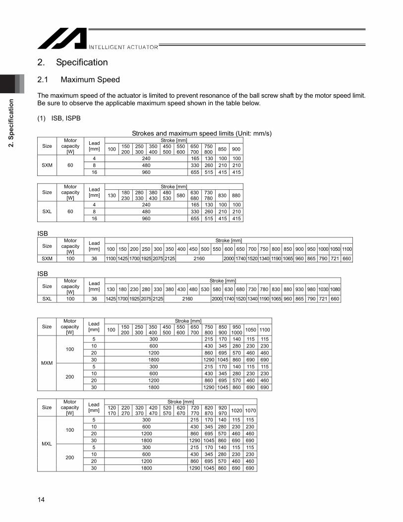
2. Specification 2.1 Maximum Speed The maximum speed of the actuator is limited to prevent resonance of the ball screw shaft by the motor speed limit. Be sure to observe the applicable maximum speed shown in the table below. (1) ISB, ISPB
Strokes and maximum speed limits (Unit: mm/s) Stroke [mm]
Size Motor
capacity [W]
Lead [mm] 100 150
200 250 300
350 400
450500
550600
650700
750800 850 900
4 240 165 130 100 1008 480 330 260 210 210SXM 60
16 960 655 515 415 415
Stroke [mm] Size
Motor capacity
[W]
Lead [mm] 130 180
230 280 330
380 430
480530 580 630
680730780 830 880
4 240 165 130 100 1008 480 330 260 210 210SXL 60
16 960 655 515 415 415 ISB
Stroke [mm] Size
Motor capacity
[W]
Lead [mm] 100 150 200 250 300 350 400 450 500 550 600 650 700 750 800 850 900 950 1000 1050 1100
SXM 100 36 1100 1425 1700 1925 2075 2125 2160 2000 1740 1520 1340 1190 1065 960 865 790 721 660 ISB
Stroke [mm] Size
Motor capacity
[W]
Lead [mm] 130 180 230 280 330 380 430 480 530 580 630 680 730 780 830 880 930 980 1030 1080
SXL 100 36 1425 1700 1925 2075 2125 2160 2000 1740 1520 1340 1190 1065 960 865 790 721 660
Stroke [mm] Size
Motor capacity
[W]
Lead [mm] 100 150
200 250 300
350 400
450500
550600
650700
750800
850900
9501000 1050 1100
5 300 215 170 140 115 11510 600 430 345 280 230 23020 1200 860 695 570 460 460
100
30 1800 1290 1045 860 690 6905 300 215 170 140 115 115
10 600 430 345 280 230 23020 1200 860 695 570 460 460
MXM
200
30 1800 1290 1045 860 690 690
Stroke [mm] Size
Motor capacity
[W]
Lead [mm] 120
170 220 270
320 370
420 470
520570
620670
720770
820870
920970 1020 1070
5 300 215 170 140 115 11510 600 430 345 280 230 23020 1200 860 695 570 460 460
100
30 1800 1290 1045 860 690 6905 300 215 170 140 115 115
10 600 430 345 280 230 23020 1200 860 695 570 460 460
MXL
200
30 1800 1290 1045 860 690 690
2. Specification
15
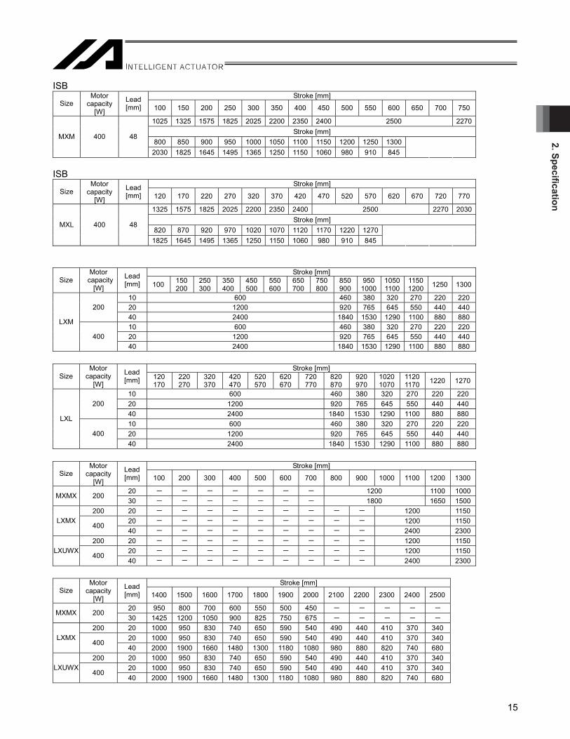
ISB Stroke [mm]
Size Motor
capacity [W]
Lead [mm] 100 150 200 250 300 350 400 450 500 550 600 650 700 750
1025 1325 1575 1825 2025 2200 2350 2400 2500 2270Stroke [mm]
800 850 900 950 1000 1050 1100 1150 1200 1250 1300 MXM 400 48
2030 1825 1645 1495 1365 1250 1150 1060 980 910 845 ISB
Stroke [mm] Size
Motor capacity
[W]
Lead [mm] 120 170 220 270 320 370 420 470 520 570 620 670 720 770
1325 1575 1825 2025 2200 2350 2400 2500 2270 2030Stroke [mm]
820 870 920 970 1020 1070 1120 1170 1220 1270 MXL 400 48
1825 1645 1495 1365 1250 1150 1060 980 910 845
Stroke [mm] Size
Motor capacity
[W]
Lead [mm] 100 150
200 250 300
350400
450500
550600
650700
750800
850900
9501000
1050 1100
1150 1200 1250 1300
10 600 460 380 320 270 220 22020 1200 920 765 645 550 440 440200 40 2400 1840 1530 1290 1100 880 88010 600 460 380 320 270 220 22020 1200 920 765 645 550 440 440
LXM
400 40 2400 1840 1530 1290 1100 880 880
Stroke [mm]
Size Motor
capacity [W]
Lead [mm] 120
170 220 270
320 370
420470
520570
620670
720770
820870
920970
10201070
1120 1170 1220 1270
10 600 460 380 320 270 220 22020 1200 920 765 645 550 440 440200 40 2400 1840 1530 1290 1100 880 88010 600 460 380 320 270 220 22020 1200 920 765 645 550 440 440
LXL
400 40 2400 1840 1530 1290 1100 880 880
Stroke [mm]
Size Motor
capacity [W]
Lead [mm] 100 200 300 400 500 600 700 800 900 1000 1100 1200 1300
20 - - - - - - - 1200 1100 1000MXMX 200 30 - - - - - - - 1800 1650 1500
200 20 - - - - - - - - - 1200 115020 - - - - - - - - - 1200 1150LXMX
400 40 - - - - - - - - - 2400 2300
200 20 - - - - - - - - - 1200 115020 - - - - - - - - - 1200 1150LXUWX
400 40 - - - - - - - - - 2400 2300
Stroke [mm]
Size Motor
capacity [W]
Lead [mm] 1400 1500 1600 1700 1800 1900 2000 2100 2200 2300 2400 2500
20 950 800 700 600 550 500 450 - - - - - MXMX 200 30 1425 1200 1050 900 825 750 675 - - - - -
200 20 1000 950 830 740 650 590 540 490 440 410 370 340 20 1000 950 830 740 650 590 540 490 440 410 370 340 LXMX
400 40 2000 1900 1660 1480 1300 1180 1080 980 880 820 740 680
200 20 1000 950 830 740 650 590 540 490 440 410 370 340 20 1000 950 830 740 650 590 540 490 440 410 370 340 LXUWX
400 40 2000 1900 1660 1480 1300 1180 1080 980 880 820 740 680

2. S
peci
ficat
ion
16
ISB Stroke [mm]
Size Motor
capacity [W]
Lead [mm] 800 850 900 950 1000 1050 1100 1150 1200 1250 1300 1350 1400 1450
1700 1750 1800 1850 1900 1950 2000 2050 2100 2150 2200 2065 1925 1805Stroke [mm]
1500 1550 1600 1650 1700 1750 1800 1850 1900 1950 2000 MXMX 400 48
1690 1590 1495 1410 1335 1265 1195 1135 1080 1025 980
Caution: (1) Do not set speeds equal to or greater than the respective ratings. Doing so may result in vibration, failure or shorter life.
(2) In the case of interpolated operation of two or more orthogonal axes, make sure the command values (settings) of speed and acceleration/deceleration do not exceed the smallest values of all speeds and accelerations/decelerations of the applicable axes. Even if any speed or acceleration/deceleration is set that exceeds the smallest speed or acceleration/deceleration among all applicable axes, the actual speed or acceleration/deceleration will be clamped to the smallest speed or acceleration/deceleration.

2. Specification
17
(2) SSPA Stroke and maximum speed (or speed to reach) limits (Unit: mm/s)
Stroke [mm] Size
Motor capacity
[W]
Lead [mm] 100 150 200 250 300 350 400 450 500 550 600 650 700 750 800 850 900 950
10 600 560 490 440 390 350 320 29020 1200 1120 990 880 780 710 640 580SXM 200 30 1800 1680 1480 1320 1180 1060 960 87010 600 530 480 430 390 36020 1200 1070 960 870 790 720MXM 400 40 2400 2150 1930 1740 1580 1440
1080 1250 750 25
620 880 1080 1250 1080 1530 1870 2160 2420 2500
LXM 750 50
620 880 1080 1250 1400 1530 1650 1770 1870
Stroke [mm]
Size Motor
capacity [W]
Lead [mm] 1000 1050 1100 1150 1200 1250 1300 1350 1400 1450 1500
10 260 240 220 - - - - - - - -
20 530 480 440 - - - - - - - -SXM 200 30 790 730 670 - - - - - - - -
10 330 300 280 250 240 220 200 - - - -
20 660 600 560 510 480 440 410 - - - -MXM 400 40 1320 1210 1120 1030 960 890 830 - - - -
1160 970 830 720 620 550750 25
1160 970 830 720 620 5502320 1950 1660 1440 1250 1100
LXM 750 50
1970 1950 1660 1440 1250 1100
Caution: (1) Do not set speeds equal to or greater than the respective ratings. Doing so may result in vibration, failure or shorter life.
(2) In the case of interpolated operation of two or more orthogonal axes, make sure the command values (settings) of speed and acceleration/deceleration do not exceed the smallest values of all speeds and accelerations/decelerations of the applicable axes. Even if any speed or acceleration/deceleration is set that exceeds the smallest speed or acceleration/deceleration among all applicable axes, the actual speed or acceleration/deceleration will be clamped to the smallest speed or acceleration/deceleration.

2. S
peci
ficat
ion
18
2.2 Acceleration/Deceleration, Payload Capacity and Rated Thrust If the payload capacity is smaller than as specified, the acceleration/deceleration can be raised beyond the applicable level. (1) ISB, ISPB
Payload capacity by acceleration/deceleration [kg] Type Size
Motor capacity
[W]
Lead [mm]
Rated acceleration/
deceleration [G]
Maximum acceleration/
deceleration [G]
Horizontal/Vertical 0.2G 0.3G 0.4G 0.5G 0.6G 0.7G 0.8G 0.9G 1.0G 1.1G 1.2G
Ratedthrust
[N]0.2 0.5 Horizontal 55 50 38 30 - - - - - - - 4 0.2 0.4 Vertical 14 13 12 - - - - - - - - 212.3
0.4 0.7 Horizontal 27 27 27 20 15 12 - - - - - 8 0.4 0.6 Vertical 7 7 7 6 5 - - - - - - 106.1
0.4 1.2 Horizontal 13 13 13 10.5 8.5 7 6 5.5 4.5 4 3.5
SXM SXL 60
16 0.4 0.8 Vertical 3.5 3.5 3.5 3.0 2.6 2.3 2 - - - - 53.1
0.2 0.5 Horizontal 85 80 60 45 - - - - - - - 5 0.2 0.4 Vertical 20 17 15 - - - - - - - - 339.7
0.4 0.7 Horizontal 45 45 45 30 23 20 - - - - - 10 0.4 0.6 Vertical 10 10 10 8 7 - - - - - - 169.8
0.4 1.2 Horizontal 23 23 23 18 15 13 11 9 8 7 6 20 0.4 1 Vertical 5 5 5 4.5 4 3.5 3 2.8 2.5 - - 84.9
0.4 1.2 Horizontal 15 15 15 11 9 7 6 5 4 3.5 3
MXM MXL 100
30 0.4 1.2 Vertical 2.5 2.5 2.5 2.2 1.9 1.7 1.5 1.4 1.2 1.1 1 56.6
0.2 0.5 Horizontal 110 100 90 80 - - - - - - - 5 0.2 0.4 Vertical 40 34 30 - - - - - - - - 683.6
0.4 0.7 Horizontal 90 90 90 66 51 40 - - - - - 10 0.4 0.6 Vertical 20 20 20 17 15 - - - - - - 341.8
0.4 1.2 Horizontal 45 45 45 35 28 23 20 17 15 13 1220 0.4 1 Vertical 10 10 10 8.5 7.5 7 6 5.5 5 170.9
0.4 1.2 Horizontal 30 30 30 24 20 17 15 13 12 10 9
MXM MXL 200
30 0.4 1.2 Vertical 6 6 6 5.5 5 4.5 4 3.5 3 2.5 2 113.9
0.4 0.4 Horizontal 45 45 45 - - - - - - - - 20 - - Vertical - - - - - - - - - - - 170.9
0.4 0.4 Horizontal 30 30 30 - - - - - - - -
Gui
de w
ith b
all r
eten
tion
mec
hani
sm (R
T) n
ot u
sed
MXMX 200 30 - - Vertical - - - - - - - - - - - 113.9
Caution: (1) Even when the acceleration/deceleration is less than the rated acceleration/deceleration, the payload capacity will not exceed the specified payload capacity at the rated acceleration/deceleration.
(2) In the case of interpolated operation of two or more orthogonal axes, make sure the command values (settings) of speed and acceleration/deceleration do not exceed the smallest values of all speeds and accelerations/decelerations of the applicable axes. Even if any speed or acceleration/deceleration is set that exceeds the smallest speed or acceleration/deceleration among all applicable axes, the actual speed or acceleration/deceleration will be clamped to the smallest speed or acceleration/deceleration.

2. Specification
19
(1) ISB, ISPB (continuous) Payload capacity by acceleration/deceleration [kg]
Type Size Motor
capacity [W]
Lead [mm]
Rated acceleration/
deceleration [G]
Maximum acceleration/
deceleration [G]
Horizontal/Vertical 0.2G 0.3G 0.4G 0.5G 0.6G 0.7G 0.8G 0.9G 1.0G 1.1G 1.2G
Ratedthrust
[N]0.4 0.7 Horizontal 90 90 90 66 51 40 - - - - - 10 0.4 0.6 Vertical 20 20 20 16 14 - - - - - - 341.8
0.4 1.2 Horizontal 45 45 45 35 28 23 20 17 15 13 1220 0.4 1 Vertical 10 10 10 8.5 7.5 7 6 5.5 5 170.9
0.4 1.2 Horizontal 15 15 15 12 10.5 9 8 7.5 7 6.5 6
LXM LXL 200
40 0.4 1.2 Vertical 4 4 4 3.5 3.1 2.8 2.5 2.2 2.0 1.8 1.6 85.5
0.4 0.7 Horizontal 120 120 120 92 73 60 - - - - - 10 0.4 0.6 Vertical 40 40 40 34 30 - - - - - - 678.3
0.4 1.2 Horizontal 90 90 90 70 57 47 40 35 30 27 2420 0.4 1 Vertical 20 20 20 17 15 14 12 11 10 - - 339.1
0.4 1.2 Horizontal 40 40 40 32 27 23 21 19 17 16 15
LXM LXL 400
40 0.4 1.2 Vertical 10 10 10 8.5 7.5 7 6 5.5 5 4.5 4 169.6
0.4 0.4 Horizontal 45 45 45 - - - - - - - - LXMX 200 20 - - Vertical - - - - - - - - - - - 170.9
0.4 0.4 Horizontal 90 90 90 - - - - - - - - 20 - - Vertical - - - - - - - - - - - 339.1
0.4 0.4 Horizontal 40 40 40 - - - - - - - - LXMX 400 40 - - Vertical - - - - - - - - - - - 169.6
0.4 0.4 Horizontal 45 45 45 - - - - - - - - LXUWX 200 20 - - Vertical - - - - - - - - - - - 170.1
0.4 0.4 Horizontal 90 90 90 - - - - - - - - 20 - - Vertical - - - - - - - - - - - 339.1
0.4 0.4 Horizontal 40 40 40 - - - - - - - -
Gui
de w
ith b
all r
eten
tion
mec
hani
sm (R
T) n
ot u
sed
LXUWX 400 40 - - Vertical - - - - - - - - - - - 169.6
Caution: (1) Even when the acceleration/deceleration is less than the rated acceleration/deceleration, the payload capacity will not exceed the specified payload capacity at the rated acceleration/deceleration.
(2) In the case of interpolated operation of two or more orthogonal axes, make sure the command values (settings) of speed and acceleration/deceleration do not exceed the smallest values of all speeds and accelerations/decelerations of the applicable axes. Even if any speed or acceleration/deceleration is set that exceeds the smallest speed or acceleration/deceleration among all applicable axes, the actual speed or acceleration/deceleration will be clamped to the smallest speed or acceleration/deceleration.

2. S
peci
ficat
ion
20
ISB Payload capacity by acceleration/deceleration [kg]
Type Size Motor
capacity [W]
Lead [mm]
Rated acceleration/
deceleration [G]
Maximum acceleration/
deceleration [G]
Horizontal/Vertical 0.4G 0.5G 0.6G 0.7G 0.8G 0.9G 1.0G 1.1G 1.2G 1.3G 1.4G
Ratedthrust
[N]0.4 2.0 Horizontal 10.0 9.0 8.2 7.5 6.7 6.0 5.5 5.0 4.5 4.3 4.10.4 1.6 Vertical 2 2 2 2 2 2 2 2 2 2 2
Payload capacity by acceleration/deceleration [kg] 1.5G 1.6G 1.7G 1.8G 1.9G 2.0G - - - - - 0.4 2.0 Horizontal 4.0 3.9 3.8 3.7 3.6 3.5 - - - - - 0.4 1.6 Vertical 2 2 - - - - - - - - -
* When the actuator is installed in horizontal orientation, acceleration / deceleration can be increased to 3.0G at maximum if gain adjustment is conducted in the offboard tuning.。
Payload capacity by acceleration/deceleration [kg] 2.1G 2.2G 2.3G 2.4G 2.5G 2.6G 2.7G 2.8G 2.9G 3.0G -
SXM SXL 100 36
- 3.0 Horizontal 3.2 2.9 2.6 2.3 2.0 1.9 1.8 1.7 1.6 1.5 -
47.2
Payload capacity by acceleration/deceleration [kg] 0.4G 0.5G 0.6G 0.7G 0.8G 0.9G 1.0G 1.1G 1.2G 1.3G 1.4G
0.4 2.0 Horizontal 20.0 19.1 18.2 17.3 16.4 15.5 14.6 13.8 13.0 12.6 12.20.4 1.6 Vertical 6 6 6 6 6 6 6 6 6 6 6
Payload capacity by acceleration/deceleration [kg] 1.5G 1.6G 1.7G 1.8G 1.9G 2.0G - - - - - 0.4 2.0 Horizontal 11.8 11.4 11.0 10.8 10.4 10.0 - - - - - 0.4 1.6 Vertical 6 6 - - - - - - - - -
* When the actuator is installed in horizontal orientation, acceleration / deceleration can be increased to 3.0G at maximum if gain adjustment is conducted in the offboard tuning.。
Payload capacity by acceleration/deceleration [kg] 2.1G 2.2G 2.3G 2.4G 2.5G 2.6G 2.7G 2.8G 2.9G 3.0G -
MXM MXL 400 48
- 3.0 Horizontal 9.4 8.8 8.2 7.6 7.0 6.6 6.2 5.8 5.4 5.0 -
141.3
Payload capacity by acceleration/deceleration [kg] 0.4G - - - - - - - - - -
Gui
de w
ith b
all r
eten
tion
mec
hani
sm (R
T) n
ot u
sed
MXMX 400 48 0.4 0.4 Horizontal 20.0 - - - - - - - - - -
141.3
Caution: (1) Even when the acceleration/deceleration is less than the rated acceleration/deceleration, the payload capacity will not exceed the specified payload capacity at the rated acceleration/deceleration.
(2) In the case of interpolated operation of two or more orthogonal axes, make sure the command values (settings) of speed and acceleration/deceleration do not exceed the smallest values of all speeds and accelerations/decelerations of the applicable axes. Even if any speed or acceleration/deceleration is set that exceeds the smallest speed or acceleration/deceleration among all applicable axes, the actual speed or acceleration/deceleration will be clamped to the smallest speed or acceleration/deceleration.

2. Specification
21
Payload capacity by acceleration/deceleration [kg] Type Size
Motor capacity
[W]
Lead [mm]
Rated acceleration/
deceleration [G]
Maximum acceleration/
deceleration [G]
Horizontal/Vertical 0.2G 0.3G 0.4G 0.5G 0.6G 0.7G 0.8G 0.9G 1.0G 1.1G 1.2G
Ratedthrust
[N]0.2 0.5 Horizontal 55 50 38 30 - - - - - - - 4 0.2 0.4 Vertical 13.5 12.5 11.5 - - - - - - - - 212.3
0.4 0.7 Horizontal 27 27 27 20 15 12 - - - - - 8 0.4 0.6 Vertical 6.5 6.5 6.5 5.5 4.5 - - - - - - 106.1
0.4 1.2 Horizontal 13 13 13 10.5 8.5 7 6 5.5 4.5 4 3.5
SXM 60
16 0.4 0.8 Vertical 3.0 3.0 3.0 2.5 2.1 1.8 1.5 - - - - 53.1
0.2 0.5 Horizontal 85 80 60 45 - - - - - - - 5 0.2 0.4 Vertical 19.5 16.5 14.5 - - - - - - - - 339.7
0.4 0.7 Horizontal 45 45 45 30 23 20 - - - - - 10 0.4 0.6 Vertical 9.5 9.5 9.5 7.5 6.5 - - - - - - 169.8
0.4 1.2 Horizontal 23 23 23 18 15 13 11 9 8 7 6 20 0.4 1 Vertical 4.5 4.5 4.5 4.0 3.5 3.0 2.5 2.3 2.0 - - 84.9
0.4 1.2 Horizontal 15 15 15 11 9 7 6 5 4 3.5 3
MXM 100
30 0.4 1.2 Vertical 2.0 2.0 2.0 1.7 1.4 1.2 1.0 0.9 0.7 0.6 0.5 56.6
0.2 0.5 Horizontal 110 100 90 80 - - - - - - - 5 0.2 0.4 Vertical 40 34 30 - - - - - - - - 683.6
0.4 0.7 Horizontal 90 90 90 66 51 40 - - - - - 10 0.4 0.6 Vertical 20 20 20 17 15 - - - - - - 341.8
0.4 1.2 Horizontal 45 45 45 35 28 23 20 17 15 13 1220 0.4 1 Vertical 10 10 10 8.5 7.5 7 6 5.5 5 - - 170.9
0.4 1.2 Horizontal 30 30 30 24 20 17 15 13 12 10 9
MXM 200
30 0.4 1.2 Vertical 6 6 6 5.5 5 4.5 4 3.5 3 2.5 2 113.9
0.4 0.4 Horizontal 45 45 45 - - - - - - - - 20 - - Vertical - - - - - - - - - - - 170.9
0.4 0.4 Horizontal 30 30 30 - - - - - - - - MXMX 200 30 - - Vertical - - - - - - - - - - - 113.9
0.4 0.7 Horizontal 90 90 90 66 51 40 - - - - - 10 0.4 0.6 Vertical 19 19 19 15 13 - - - - - - 341.8
0.4 1.2 Horizontal 45 45 45 35 28 23 20 17 15 13 1220 0.4 1 Vertical 9 9 9 7.5 6.5 6 5 4.5 4 - - 170.9
0.4 1.2 Horizontal 15 15 15 12 10.5 9 8 7.5 7 6.5 6
LXM 200
40 0.4 1.2 Vertical 3 3 3 2.5 2.1 1.8 1.5 1.2 1.0 0.8 0.6 85.5
0.4 0.7 Horizontal 120 120 120 92 73 60 - - - - - 10 0.4 0.6 Vertical 40 40 40 34 30 - - - - - - 678.3
0.4 1.2 Horizontal 90 90 90 70 57 47 40 35 30 27 2420 0.4 1 Vertical 20 20 20 17 15 14 12 11 10 - - 339.1
0.4 1.2 Horizontal 40 40 40 32 27 23 21 19 17 16 15
LXM 400
40 0.4 1.2 Vertical 10 10 10 8.5 7.5 7 6 5.5 5 4.5 4 169.6
0.4 0.4 Horizontal 45 45 45 - - - - - - - - LXMX 200 20 - - Vertical - - - - - - - - - - - 170.9
0.4 0.4 Horizontal 90 90 90 - - - - - - - - 20 - - Vertical - - - - - - - - - - - 339.1
0.4 0.4 Horizontal 40 40 40 - - - - - - - - LXMX 400 40 - - Vertical - - - - - - - - - - - 169.6
0.4 0.4 Horizontal 45 45 45 - - - - - - - - LXUWX 200 20 - - Vertical - - - - - - - - - - - 170.1
0.4 0.4 Horizontal 90 90 90 - - - - - - - - 20 - - Vertical - - - - - - - - - - - 339.1
0.4 0.4 Horizontal 40 40 40 - - - - - - - -
Gui
de w
ith b
all r
eten
tion
mec
hani
sm (R
T) u
sed
LXUWX 400 40 - - Vertical - - - - - - - - - - - 169.6
Caution: (1) Even when the acceleration/deceleration is less than the rated acceleration/deceleration, the payload capacity will not exceed the specified payload capacity at the rated acceleration/deceleration.
(2) In the case of interpolated operation of two or more orthogonal axes, make sure the command values (settings) of speed and acceleration/deceleration do not exceed the smallest values of all speeds and accelerations/decelerations of the applicable axes. Even if any speed or acceleration/deceleration is set that exceeds the smallest speed or acceleration/deceleration among all applicable axes, the actual speed or acceleration/deceleration will be clamped to the smallest speed or acceleration/deceleration.

2. S
peci
ficat
ion
22
ISB Payload capacity by acceleration/deceleration [kg]
Type Size Motor
capacity [W]
Lead [mm]
Rated acceleration/
deceleration [G]
Maximum acceleration/
deceleration [G]
Horizontal/Vertical 0.4G 0.5G 0.6G 0.7G 0.8G 0.9G 1.0G 1.1G 1.2G 1.3G 1.4G
Ratedthrust
[N]0.4 2.0 Horizontal 10.0 9.0 8.2 7.5 6.7 6.0 5.5 5.0 4.5 4.3 4.10.4 1.6 Vertical 1.5 1.5 1.5 1.5 1.5 1.5 1.5 1.5 1.5 1.5 1.5
Payload capacity by acceleration/deceleration [kg] 1.5G 1.6G 1.7G 1.8G 1.9G 2.0G - - - - - 0.4 2.0 Horizontal 4.0 3.9 3.8 3.7 3.6 3.5 - - - - - 0.4 1.6 Vertical 1.5 1.5 - - - - - - - - -
* When the actuator is installed in horizontal orientation, acceleration / deceleration can be increased to 3.0G at maximum if gain adjustment is conducted in the offboard tuning.。
Payload capacity by acceleration/deceleration [kg] 2.1G 2.2G 2.3G 2.4G 2.5G 2.6G 2.7G 2.8G 2.9G 3.0G -
SXM 100 36
- 3.0 Horizontal 3.2 2.9 2.6 2.3 2.0 1.9 1.8 1.7 1.6 1.5 -
47.2
Payload capacity by acceleration/deceleration [kg] 0.4G 0.5G 0.6G 0.7G 0.8G 0.9G 1.0G 1.1G 1.2G 1.3G 1.4G
0.4 2.0 Horizontal 20.0 19.1 18.2 17.3 16.4 15.5 14.6 13.8 13.0 12.6 12.20.4 1.6 Vertical 6 6 6 6 6 6 6 6 6 6 6
Payload capacity by acceleration/deceleration [kg] 1.5G 1.6G 1.7G 1.8G 1.9G 2.0G - - - - - 0.4 2.0 Horizontal 11.8 11.4 11.0 10.8 10.4 10.0 - - - - - 0.4 1.6 Vertical 6 6 - - - - - - - - -
* When the actuator is installed in horizontal orientation, acceleration / deceleration can be increased to 3.0G at maximum if gain adjustment is conducted in the offboard tuning.。
Payload capacity by acceleration/deceleration [kg] 2.1G 2.2G 2.3G 2.4G 2.5G 2.6G 2.7G 2.8G 2.9G 3.0G -
MXM 400 48
- 3.0 Horizontal 9.4 8.8 8.2 7.6 7.0 6.6 6.2 5.8 5.4 5.0 -
141.3
Payload capacity by acceleration/deceleration [kg] 0.4G - - - - - - - - - -
Gui
de w
ith b
all r
eten
tion
mec
hani
sm (R
T) u
sed
MXMX 400 48 0.4 0.4 Horizontal 20.0 - - - - - - - - - -
141.3
Caution: (1) Even when the acceleration/deceleration is less than the rated acceleration/deceleration, the payload capacity will not exceed the specified payload capacity at the rated acceleration/deceleration.
(2) In the case of interpolated operation of two or more orthogonal axes, make sure the command values (settings) of speed and acceleration/deceleration do not exceed the smallest values of all speeds and accelerations/decelerations of the applicable axes. Even if any speed or acceleration/deceleration is set that exceeds the smallest speed or acceleration/deceleration among all applicable axes, the actual speed or acceleration/deceleration will be clamped to the smallest speed or acceleration/deceleration.

2. Specification
23
(2) SSPA
Payload capacity by acceleration/deceleration [kg] Size Type
Motor capacity
[W]
Lead [mm]
Rated acceleration/
deceleration [G]
Maximum acceleration/
deceleration [G]
Horizontal/Vertical 0.2G 0.3G 0.4G 0.5G 0.6G 0.7G 0.8G 0.9G 1.0G 1.1G 1.2G
Ratedthrust
[N]0.7 Horizontal 90 90 90 72 60 50 - - - - - 10 0.4 0.6 Vertical 12 12 12 10 8 - - - - - - 341.8
1.2 Horizontal 45 45 45 36 30 26 22.5 19.5 17 - - 20 0.4 1.2 Vertical 6 6 6 4.8 4 3.4 3 2.7 2.4 - - 170.9
1.2 Horizontal 30 30 30 24 20 17 15 13 12 11 10
SXM - 200
30 0.4 1.2 Vertical 4 4 4 3.2 2.7 2.3 2 1.7 1.4 1.2 1 113.9
0.7 Horizontal 120 120 120 96 80 70 - - - - - 10 0.4 0.6 Vertical 25 25 25 20 16.5 - - - - - - 678.3
1.2 Horizontal 90 90 90 72 60 51 45 39 34 - - 20 0.4 1.2 Vertical 12 12 12 9.6 8 6.9 6 5.3 4.8 - - 339.1
1.2 Horizontal 45 45 45 36 30 25.5 22.5 19.5 17 15 13.5
MXM - 400
40 0.4 1.2 Vertical 6 6 6 4.8 4 3.4 3 2.7 2.4 2.2 2 169.6
Horizontal 120 120 120 96 80 69 60 53 48 44 4025 0.4 1.2
Vertical 25 25 25 20 17 14 13 11 10 9 8 510
Horizontal 60 60 60 48 40 34 30 27 24 22 20
Gui
de w
ith b
all
rete
ntio
n m
echa
nism
(R
T) n
ot u
sed
750
50 0.4 1.2 Vertical 12 12 12 10 8 7 6 5 5 4 4
255
Horizontal 120 120 120 96 80 69 60 53 48 44 4025 0.4 1.2
Vertical 23 23 23 18 15 12 11 9 8 7 6 510
Horizontal 60 60 60 48 40 34 30 27 24 22 20
LXM
Gui
de w
ith b
all
rete
ntio
n m
echa
nism
(R
T) u
sed
750
50 0.4 1.2 Vertical 10 10 10 8 6 5 4 3 3 2 2
255
Caution: (1) Even when the acceleration/deceleration is less than the rated acceleration/deceleration, the payload capacity will not exceed the specified payload capacity at the rated acceleration/deceleration.
(2) In the case of interpolated operation of two or more orthogonal axes, make sure the command values (settings) of speed and acceleration/deceleration do not exceed the smallest values of all speeds and accelerations/decelerations of the applicable axes. Even if any speed or acceleration/deceleration is set that exceeds the smallest speed or acceleration/deceleration among all applicable axes, the actual speed or acceleration/deceleration will be clamped to the smallest speed or acceleration/deceleration.

2. S
peci
ficat
ion
24
2.3 Driving System/Position Detector The actuator is driven by the AC servo control method.
(1) ISB, ISPB Ball screw specification
Size Motor
capacity [W]
Lead [mm]
Encoder pulses*1 Type Diameter ISB series ISPB series
4 8 SXM
SXL 60 16
Rolled φ 12mm C10 C5 or equivalent
ISB- SXM/SXL 100 36 Rolled φ 12mm C10 -
5 10 20
MXM MXL 100
30
Rolled φ 16mm C10 C5 or equivalent
5 10 20
MXM MXL 200
30
Rolled φ 16mm C10 C5 or equivalent
ISB- MXM/MXL 400 48 Rolled φ 16mm C10 -
20 MXMX 200 30 Rolled φ 16mm C10 C5 or equivalent
ISB- MXMX 400 48 Rolled φ 16mm C10 -
10 20 LXM
LXL 200 40
Rolled φ 20mm C10 C5 or equivalent
10 20 LXM
LXL 400 40
Rolled φ 20mm C10 C5 or equivalent
LXMX 200 20 Rolled φ 20mm C10 C5 or equivalent
20 LXMX 400 40 Rolled φ 20mm C10 C5 or equivalent
LXUWX 200 20 Rolled φ 20mm C10 C5 or equivalent
20 LXUWX 400 40
Incremental Absolute
16384
Battery-lessAbsolute 131072
Rolled φ 20mm C10 C5 or equivalent
*1 Number of pulses input to the controller. (Note) In Pulse Train Control Mode for SCON-CB Controller, the setting of denominator and numerator for
electronic gear ratio is restricted by the upper limit of internal calculation. For battery-less absolute type, it will be restricted even more as the number of encoder pulse is high. In case it gets restricted, have a countermeasure such as to adjust the movement per unit. [Refer to the instruction manuals of SCON-CB controller for details]

2. Specification
25
(2) SSPA The actuator is driven by the AC servo control method.
Ball screw Size Motor capacity [W]
Lead [mm]
Encoder pulses*1 Type Diameter
10 20 SXM 200 30
Rolled φ 16 mm C5 or equivalent
10 20 MXM 400 40
Rolled φ 20 mm C5 or equivalent
25 LXM 750 50
16384
Rolled φ 25 mm C5 or equivalent
*1 This is a number of pulses entered in the controller.

2. S
peci
ficat
ion
26
2.4 Positioning Precision
Functions
Item ISB
ISPB (Incremental
Absolute)
ISPB (Battery-less
Absolute) SSPA
Positioning repeatability*1 ±0.01 mm ±0.005 mm ±0.003 mm ±0.005 mm Backlash*1 0.05 mm or less 0.02 mm or less 0.02 mm or less 0.02 mm or less
*1 Initial value 2.5 Allowable Moment of the Actuator (1) ISB, ISPB
Static allwable moment [N m] Dynamic allowable moment [N m] Size Ma Ma Mb Mc Mb Mc
Allowable overhang load length (L)
SXM 143.8 205.4 336.0 32.9 47.0 76.8 Ma direction: 450 Mb or Mc direction: 450
SXL 216.0 308.5 415.1 46.3 66.2 89.0 Ma direction: 550 Mb or Mc direction: 550
MXM 341.5 487.0 796.5 81.0 116.0 189.0 Ma direction: 600 Mb or Mc direction: 600
MXL 560.3 800.2 1030.8 123.0 176.0 227.0 Ma direction: 600 Mb or Mc direction: 600
MXMX 341.5 487.0 796.5 81.0 116.0 189.0 Ma direction: 600 Mb or Mc direction: 600
LXM 560.2 800.1 1325.3 123.0 176.0 291.0 Ma direction: 750 Mb or Mc direction: 750
LXL 774.6 1106.4 1566.3 162.0 231.0 327.0 Ma direction: 900 Mb or Mc direction: 900
LXMX 560.2 800.1 1325.3 123.0 176.0 291.0 Ma direction: 750 Mb or Mc direction: 750
LXUWX 746.7 1066.4 1086.7 299.0 427.0 292.0 Ma direction: 1250 Mb or Mc direction: 1250
Direction of moment
Ma direction
Mb or Mc direction
Ma direction Mb direction
Mc direction
Direction of allowable overhang
L

2. Specification
27
L [mm] SXM 30 SXL 30 MXM 37.5 MXL 37.5 MXMX 37.5 LXM 44.5 LXL 44.5 LXMX 44.5 LXUWX 44.5
Caution: Make sure the load installed on the actuator is not longer than the allowable overhang load length (L). If the load is longer than L, vibration may occur or the settling time may increase depending on the position of center of gravity position or weight of the work part. If a moment exceeding the allowable moment is applied, not only the life of the guide will become shorter but vibration or longer settling time may also result.
L Reference position
Reference position for moment calculation

2. S
peci
ficat
ion
28
(2) SSPA
Static allowable moment [N m] Dynamic allowable moment [N m] Size
Ma Mb Mc Ma Mb Mc Allowable overhang
load length (L)
SXM 190 190 530 43.4 43.4 116 Ma direction: 450 Mb or Mc direction: 450
MXM 470 470 1210 107 107 276 Ma direction: 600 Mb or Mc direction: 600
LXM 750 750 1850 162 162 391 Ma direction: 750 Mb or Mc direction: 750
L [mm] SXM 45.0 MXM 48.5 LXM 50.5
Caution: Make sure the load installed on the actuator is not longer than the allowable overhang load length (L). If the load is longer than L, vibration may occur or the settling time may increase depending on the position of center of gravity position or weight of the work part. If a moment exceeding the allowable moment is applied, not only the life of the guide will become shorter but vibration or longer settling time may also result.
Reference position for moment calculation
Mb or Mc direction
Direction of moment Direction of allowable overhang
Ma direction Mb direction
Mc direction Ma direction
L
L Reference position

3. Life
29
3. Life The mechanical life of the actuator is represented by that of the guide receiving the greatest moment load. Operation life of the linear guide is to be determined by the total driving distance which can reach without having 90% flaking (peeling on rail surface). Operation life can be figured out with the calculation method shown below. 3.1 How to Calculate Operation Life For the operation life of the linear guide, use the dynamic allowable moment stated in 1.2 Specifications, and figure out with the formula below.
L = ・10000km
L : Operation life (km) CM : Dynamic allowable moment (N・m) M : Moment to work (N・m) 10000km : Standard rated life of Single-Axis actuator In addition, have a calculation for the drop of life with the formula below if there is a concern that the life could drop due to the condition of vibration or way to be attached.
L = ・ ・ ・10000km
L : Operation life (km) CM : Dynamic allowable moment (N・m) M : Moment to work (N・m) fws : Standard operational coefficient fw : Load coefficient fα : Attachment coefficient
10000km : Standard rated life of Single-Axis actuator
Explained below is regarding the standard operational coefficient fws, load coefficient fw and attachment coefficient fα. Refer to the contents below to set them up. [Standard operatinal coefficient fws] For Single-Axis actuator described in this manual, fws = 1.2. It is a coefficient defined for each model, some models such as RCS3 high-speed type is 1.35.
CM
M
3
CM
M
3
fw
fws 1
fα

3. L
ife
30
[Load coefficient fw] It is a coefficient to consider the life drop due to operational conditions.
Load coefficient fw Operation Condition Reference for acceleration/deceleration
1.0 to 1.5 Small vibration or impact in slow operation 1.0G or less
1.5 to 2.0 Medium level vibration or impact, sudden acceleration and Immediate braking 1.0G to 1.2G
[Attachment coefficient fα] Attachment coefficient fα is a coefficient to consider the life drop due to the condition of actuator attachment.
Attachment coefficient fα 1.0 1.2 1.5
Attachment in whole area Attachment on both ends Attachment on spots
Attached condition
* As the figures are those in common for each manual, they are not for IS(P)B, SSPA Replace to figures for IS(P)B, SSPA and select the attachment coefficient.
* Even when in attachment in whole area, and the actuator is seated in the whole length of the product, select 1.2 or 1.5 for the attachment coefficient depending on the position of screw fixing.
* For attachment in whole area, use all of the tapped holes (counterbored holes) on the seat surface to fix.
3.2 Operation Life The operation life depends on the moment to work. With light load, it will be longer than 10,000km, the standard rated life. With no consideration of vibration and attachment condition, the operation life is 80,000km according to the calculation with formula in the previous page underassumption that 0.5 CM (half of dynamic allowable moment) of moment is applied on. It shows that it can be 8 times longer than the standard rated life, which is 10,000km.

4. Installation and Storage/Preservation Environment
31
4. Installation and Storage/Preservation Environment 4.1 Installation Environment The actuator should be installed in a location other than those specified below. In general, the installation environment should be one in which an operator can work without protective gear. Also provide sufficient work space required for maintenance inspection. • Where the actuator receives radiant heat from strong heat sources such as heat treatment furnaces • Where the ambient temperature exceeds the range of 0 to 40°C • Where the temperature changes rapidly and condensation occurs • Where the relative humidity exceeds 85% RH • Where the actuator receives direct sunlight • Where the actuator is exposed to corrosive or combustible gases • Where the ambient air contains a large amount of powder dust, salt or iron (at level exceeding what is normally
expected in an assembly plant) • Where the actuator is subject to splashed water, oil (including oil mist or cutting fluid) or chemical solutions • Where the actuator receives impact or vibration If the actuator is used in any of the following locations, provide sufficient shielding measures: • Where noise generates due to static electricity, etc. • Where the actuator is subject to a strong electric or magnetic field • Where the actuator is subject to ultraviolet ray or radiation 4.2 Storage/Preservation Environment The storage/preservation environment should be similar to the installation environment. In addition, make sure condensation will not occur when the actuator is to be stored or preserved for a long period of time. Unless specified, we do not include drying agents when shipping the actuator. If you are storing the actuator in an environment where condensation might occur, you must treat the entire shipping box, or treat the actuator itself after unpacking, to prevent condensation. The unit can withstand temperatures up to 60ºC during a short storage/preservation period, but only up to 50ºC if the storage/preservation period is longer than one month. The actuator should be lying flat during storage/preservation. If the actuator is to be stored in a packed state, follow the specified actuator position if indicated.

5. T
rans
port
atio
n
32
Motor cover
5. Transportation 5.1 Handling a Single Axis 5.1.1 Handling the Packed Unit Unless otherwise instructed, each actuator axis is packed individually and shipped. • Do not bump or drop the package. The package is not specially designed to withstand the impact of dropping
or bumping. • The operator should not carry heavy shipping boxes by himself. Transport the package using an appropriate
transport means. • If the shipping box is to be left standing or transported, it should be in a horizontal position. If the packing
specification is instructed, follow the instruction. • Do not climb on top of the shipping box. • Do not place heavy objects, or objects having a section where loads concentrate, on top of the shipping box. 5.1.2 Handling an Actuator after Unpacking (1) ISB, ISPB • Do not transport the actuator by holding the cables or move it by pulling the cables. • When transporting the actuator, do so by holding the base. • Be careful not to bump the actuator during transport. • Do not exert an excessive force on any part of the actuator. • In the case of the high-precision straightness specification type, be careful not to make a damage and the
traces of hitting at the base bottom. There is a possibility that the running accuracy changes.
(2) SSPA • Four eye bolts are installed, so use these eye bolts to transport the actuator. The SSPA, when unpacked, looks
like the condition shown in the figure below. • Do not hold the motor cover when transporting the SSPA. Doing so may damage the cover due to the weight
of the actuator or the main unit may fall. • Do not transport the actuator by holding the cable, or move it by pulling the cable. • Be careful not to bump the actuator against anything when transporting it. • Do not apply excessive force on any of the actuator parts. • In the case of the high-precision straightness specification type, be careful not to make a damage and the
traces of hitting at the base bottom. There is a possibility that the running accuracy changes.
M8 eye bolt

5. Transportation
33
5.2 Handling an Cartesian Robot (ICS) Take note of the following points when transporting a set of axes that have been combined. 5.2.1 Handling a Package Before shipment, combined axes are packed in an outer frame nailed to the base made of square lumbers. Each slider is secured to prevent accidental movement during transport. Each actuator end is also secured to prevent oscillating due to external vibration. • Do not bump or drop the package. The package is not designed to withstand the impact of dropping or
bumping. • An operator must not attempt to carry a heavy package alone. Transport the package using an appropriate
transport means. • When hoisting the package using ropes, etc., support the square lumber base at the reinforcements at the
bottom. Similarly when lifting the package with a forklift, insert the forks at the bottom of the square lumber base.
• When setting down the package, be careful not to let the package receive shock or bounce. • Do not step onto the package. • Do not put any article on the package which may deform or damage the package. 5.2.2 Handling an Actuator after Unpacking • Secure the sliders to prevent sudden movement during transport. • If any end of the actuator is overhanging, secure it properly to avoid significant movement due to external
vibration. • If the actuator assembly is transported without the ends being secured, do not apply an impact of 0.3 G or
more. • When hoisting the actuator using ropes, etc., use appropriate cushioning materials to protect the actuator
against strain or distortion. Also keep a stable, horizontal posture. If necessary, use the tapped mounting holes provided on the bottom face of the base to install hoisting jigs.
• Be careful not to apply a load on any of the actuator brackets or covers or on the connector box. Also, do not allow the cable to be pinched or deformed excessively.

5. T
rans
port
atio
n
34
5.3 Handling an Actuator Assembled to a Mechanical System When transporting an actuator that has been assembled to a mechanical system, as the whole system, take note of the following points: • Secure the sliders to prevent sudden movement during transport. • If any end of the actuator is overhanging, secure it properly to avoid significant movement due to external
vibration. • If the actuator assembly is transported without the ends being secured, do not apply an impact of 0.3 G or
more. • When hoisting the mechanical system using ropes, etc., prevent the actuator, connector box, etc., from
receiving a load. Also make sure the cables are not pinched or deformed unnaturally.

6. Installation
35
6. Installation 6.1 Installation Orientations Actuators are subject to certain limitations regarding their installation orientations. If an actuator is installed in an orientation not allowed for that actuator, the stainless sheet may break or other problems may occur.
: Installable : Unavailable to mount less than 1300mm for stroke x: Not Installable
Type Horizontal installation Vertical installation Sideway installation Ceiling mount installation
ISB, ISPB SXM/SXL/MXM/ MXL/LXM/LXL
ISB, ISPB MXMX/LXMX/
LXUWX X X
SSPA
Installation orientations
Horizontal Vertical Sideway Ceiling mount

6. In
stal
latio
n
36
Caution:
1. When installing the actuator vertically, make sure the motor comes to the top. When the actuator is installed with the motor at the bottom, there shouldn’t be any problems during normal operations. If the actuator is not operated for an extended period of time, however, depending on the ambient environment (especially at high temperature) grease may separate and base oil may flow into the motor unit, causing problems on rare occasions. In the case of Sideway installation, base oil may flow out from the aperture on the side of the actuator, causing problems on rare occasions.
2. If the actuator is installed in horizontally oriented wall mount, it is easy for a foreign object to get inside the actuator from the opening on the side of the actuator.
3. In the Ceiling mount installation, the screw cover may bend, and it will be likely to interfere with the work part. ISB, when it exceeds the stroke 600mm, SSPA, when it exceeds the stroke 800mm, separate the work etc from slider seating surface and install.
Type Stroke Distance
600mm or more less than 1000mm 5mm or more ISB
ISPB 1000mm or more less than 1300mm 10mm or more
SSPA 800mm or more less than 1500mm 5mm or more
A
Work seating surface

6. Installation
37
6.2 Installing the Actuator 6.2.1 Installation Method
• Use the threaded holes on the back of the base to install the actuator. Actuators of intermediate support type
(MXMX/LXMX/LXUWX) don’t have threaded holes. Actuators have through holes, in addition to the aforementioned threaded holes, so that the actuator can be installed using hexagonal socket-head bolts that are guided through from the actuator side. If the throw holes are used, remove the screw cover and install them from the top surface.
• Actuators of intermediate support type (MXMX/LXMX/LXUWX) are installed in the same way as the corresponding actuators without intermediate support. However, be careful not to remove or get caught by the wire rope for the intermediate support during installation.
• When positioning pins are used, use pins with an engagement tolerance of h7 or equivalent. • Positioning can be performed by pushing the reference surface on the side of the base. [Refer to 6.2.2,
"Precision of the Installation Surface."] • Use high-tension bolts conforming to ISO 10.9 or higher. • When the threaded holes are used, determine the required thread length as specified below:
• ISB, ISPB Depth of threaded hole > Thread engagement length > Nominal thread size x 1.8
• SSPA Depth of threaded hole > Thread engagement length > Nominal thread size
• If the through holes are used for installation, provide the following effective engagement length, whichever is applicable, for the female thread:
• If the female thread is made of steel, same as the nominal diameter • If the female thread is made of aluminum, 1.8 times of nominal diameter
• If the bolt seating surface is aluminum, or the through holes are used, also use high-tension bolts with dedicated washers. Failure to do so may cause the seating surface to buckle.
Dedicated washer for high-tension bolt (supplied)
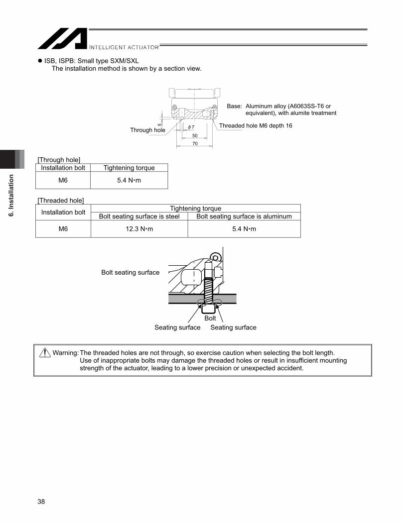
6. In
stal
latio
n
38
Bolt Seating surface Seating surface
Bolt seating surface
ISB, ISPB: Small type SXM/SXL The installation method is shown by a section view.
[Through hole] Installation bolt Tightening torque
M6 5.4 N m
[Threaded hole]
Tightening torque Installation bolt Bolt seating surface is steel Bolt seating surface is aluminum
M6 12.3 N m 5.4 N m
Warning: The threaded holes are not through, so exercise caution when selecting the bolt length. Use of inappropriate bolts may damage the threaded holes or result in insufficient mounting strength of the actuator, leading to a lower precision or unexpected accident.
Threaded hole M6 depth 16
Through hole
Base: Aluminum alloy (A6063SS-T6 or equivalent), with alumite treatment
5
50
70
7

6. Installation
39
Bolt seating surface
Seating surface Seating surface
Bolt
ISB, ISPB: Medium type MXM/MXL/MXMX, Large type LXM/LXL/LXMX/LXUWX The installation method is shown by a section view.
(Note) Threaded hole indicated with (*) in the figure above is not provided on the intermediate support type
(MXMX/LXMX/LXUWX). [Through hole] Installation bolt Tightening torque
M8 11.5 N m
[Threaded hole]
Tightening torque Installation bolt Bolt seating surface is steel Bolt seating surface is aluminum
M8 30.0 N m 11.5 N m
Warning: The threaded holes are not through, so exercise caution when selecting the bolt length. Use of inappropriate bolts may damage the threaded holes or result in insufficient mounting strength of the actuator, leading to a lower precision or unexpected accident.
Through hole Through hole
Threaded hole, M8 depth 20 (*)
Base: Aluminum alloy (A6063SS-T6 or equivalent), with alumite treatment
Threaded hole,M8 depth 20 (*) 9
7090
7 9
90120
8

6. In
stal
latio
n
40
Bolt seating surface
Seating surface Seating surface
Bolt
SSPA The installation method is shown by a section view.
L [mm] SXM 6 MXM 8 LXM 10 [Through hole]
Installation bolt Tightening torque
M6 5.4 N m
M8 11.5 N m
[Threaded hole]
Tightening torque Installation bolt Bolt seating surface is steel Bolt seating surface is aluminum
M6 12.3 N m 5.4 N m
M8 30.0 N m 11.5 N m
Warning: The threaded holes are not through, so exercise caution when selecting the bolt length. Use of inappropriate bolts may damage the threaded holes or result in insufficient mounting strength of the actuator, leading to a lower precision or unexpected accident.
φ9
L
φ15Through hole,SXMM6 length below neck * 13.5 mm min. for iron (Female screw depth of 9 mm min.) 16.5 mm min. for aluminum (Female screw depth of 12 mm min.)MXMM6 length below neck * 17.5 mm min. for iron (Female screw depth of 12 mm min.) 21.5 mm min. for aluminum (Female screw depth of 16 mm min.)LXMM8 length below neck * 22 mm min. for iron (Female screw depth of 12 mm min.) 26 mm min. for aluminum (Female screw depth of 16 mm min.)
Threaded hole, SXMM6 screw-in length6 mm min. and less than 9 mm MXMM8 screw-in length8 mm min. and less than 12 mm LXMM8 screw-in length12 mm min. and less than 16 mm
Base: Cast iron, coated

6. Installation
41
6.2.2 Precision of the Installation Surface • The frame on which the actuator is installed shall have sufficient structural rigidity to remain free from vibration,
etc. • The basis of measurement of the running accuracy of the slider is from the lower side and motor side to right
side. If accuracy for its run is required, use these surfaces as a datum of the installation. In view of the motor side, the parallelism of the quasi-reference surface of left side to the reference surface is 0.1mm or less.
• The surface where the actuator, excluding the high-precision straightness specification (model number: ST (optional)), will be mounted should be machined or be equally level, and the flatness between the actuator and the frame should be within 0.05 mm/m. If the installation surface is rough, abnormal noise or other problems may occur due to poor contact of the actuator.
• Install the actuator, excluding the high-precision straightness specification (model number: ST (optional)), after removing any dirt on the base surface on a flat surface with a precision of the flatness of 0.02 mm/m. [For the high-precision straightness specification (model number: ST (optional)), refer to 10.8, “High-Precision Straightness Specification.”]
• Provide enough space around the actuator so that maintenance work can be carried out.
ISB, ISPB: Small type SXM/SXL, Medium type MXM/MXL/MXMX, Large type LXM/LXL/LXMX/LXUWX
Slider reference surface (side) Slider reference surface (top)
Reference surface (side)
Reference surface (bottom)
View from the front side
Quasi-reference surface
Motor side
View from the upper side
Quasi-reference surfaceReference surface
• When using the base or slider reference surface (side), provide a contact surface of the following dimension.
Dimension of the contact surface to the reference surface
Size Reference Surface Dimension A Slider reference surface (side) 2 to 9 S Base reference surface (side) 3 to 5 Slider reference surface (side) 2 to 9 M Base reference surface (side) 3 to 7.5 Slider reference surface (side) 2 to 9 L Base reference surface (side) 3 to 8

6. In
stal
latio
n
42
SSPA Unless it is the optional rust-proof model (model code: MD), there is no rust-proof treatment (plating or paint coating) conducted on the base datum surface (bottom surface and datum side surface) nor slider datum surface (top surface and datum side surface). Before installing the actuator and the work part, remove any dirt or oil from the reference surface with a waste cloth soaked with alcohol and grease, wipe it off again with a dry waste cloth, and brush paint it with anti-corrosion oil. (JIS K 2246 NP-3-1 or equivalent anti-corrosion oil is applied when shipped from IAI.)
Slider reference surface (side)On the right facing from the motor
Slider reference surface (top)
Reference surface (side)On the right facing from the motor
Reference surface (bottom)
Motor side
View from the upper side
Quasi-reference surfaceReference surface
Quasi-reference surface
Shoulder dimensions to the base and slider reference surfaces (side)
Type A Slider reference surface (side) 2 to 9 Base reference surface (side) 3 to 8

6. Installation
43
6.3 Installing the Load on the Slider • The slider has threaded holes, so affix the load using these holes. The affixing method shall conform to the
method for installing the actuator. • Similarly when the slider is affixed and actuator is moved, install the slider using these threaded holes on the
slider. • The slider has two reamed holes. If repeatability is required after removal/re-installation, use positioning pins.
If squareness is required, use one positioning pin and make installation adjustment. • After removal/re-installation, repeatability can also be ensured by pushing the reference surface on the side of
the base. • Use high-tension bolts conforming to ISO 10.9 or higher. • When the threaded holes are used, determine the required thread length as specified below:
• ISB, ISPB Depth of threaded hole > Thread engagement length > Nominal thread size x 1.8
• SSPA Depth of threaded hole > Thread engagement length > Nominal thread size
ISB, ISPB: Small type SXM/SXL
SXM slider SXL slider
Tightening torque Installation bolt Bolt seating surface is steel Bolt seating surface is aluminum
M6 12.3 N m 5.4 N m
(Note) When using positioning holes, use pins with an engagement tolerance of h7 or equivalent.
2-∅6H7, depth 10 4-M6 depth 18
2-∅6H7, depth 10 8-M6 depth 18

6. In
stal
latio
n
44
2-∅8H7, depth 10 8-M8, depth 20 12-M8, depth 20 2-∅8H7, depth 10
ISB, ISPB: Medium type MXM/MXL/MXMX
MXM/MXMX slider MXL slider
Tightening torque Installation bolt Bolt seating surface is steel Bolt seating surface is aluminum
M6 12.3 N m 5.4 N m
M8 30.0 N m 11.5 N m
(Note) When using positioning holes, use pins with an engagement tolerance of h7 or equivalent.
ISB, ISPB: Large type LXM/LXL/LXMX/LXUWX
LXM/LXMX slider LXL slider
150 ±
0.02
40
8
10601080
2 x 2- 8H7, depth 102 x 4-M87, depth 20
150
40106010
80 90250
150
150 ±
0.02
8
LXUWX slider
Tightening torque Installation bolt Bolt seating surface is steel Bolt seating surface is aluminum
M8 30.0 N m 11.5 N m
(Note) When using positioning holes, use pins with an engagement tolerance of h7 or equivalent.
712
0±0
.02
120
607090
2515
2515
120
712
0±0
.02
120
75
120 1515150
3090304070402-∅8H7, depth 10
4-M6, depth 18 4-M8, depth 18
4-M6, depth 18 2-∅8H7, depth 10 4-M8, depth 18
150
±0.02
75
8
3090301512015
150
150
150
±0.0
2
90
8
459045
1016010180
150
3012030

6. Installation
45
SSPA: Small type SXM
Tightening torque Installation bolt Bolt seating surface is steel Bolt seating surface is aluminum
M6 12.3 N m 5.4 N m
SSPA: Medium type MXM
Tightening torque Installation bolt Bolt seating surface is steel Bolt seating surface is aluminum
M8 30.0 N m 11.5 N m
6.5
8598 6.5
±0.0
2
17.555 ±0.0217.5
7.537.537.57.56-M6 depth 9
90
70
Slider reference surface
2-φ6H7 depth 8
1202570 ±0.0225
9±0
.02
911
012
8
1050501089
6-M8 depth 12
Slider reference surface
2-φ8H7 depth 10

6. In
stal
latio
n
46
100 0.02
65 65
351
10 10
25 252- Ø 8 H7 0+0.015
920.0
9531
150
110
SSPA: Large type LXM
Tightening torque Installation bolt Bolt seating surface is steel Bolt seating surface is aluminum
M8 30.0 N m 11.5 N m
(Note) When using two positioning holes, use a pin with a hole of h7 or equivalent and another with a hole of g6.
Seating surface
Bolt Bolt
Bolt seating surface
6-M8, depth 16
Slider reference surface
depth 12
Seating surface Seating surface Seating surface

6. Installation
47
6.4 Using T-slots M4 T-slots for installing the connector box, etc. are provided on the side face of the base of ISB or ISPB, when configuring the orthogonal axes. (See the figure below.) You can also use these T-slots freely for installing sensors, securing wires or for other purposes as necessary.
Caution: Square nuts are recommended for use with T-slots, but general hexagonal nuts can also be used. When installing blots in T-slots, pay attention to the length of each bolt to prevent the bolt end from contacting the bottom of the T-slot.
Distance from bolt end
Square nut (or hexagonal nut)
Installed part
Bolt
4.5 1.5
7.3
4.3

7. C
onne
ctin
g th
e C
ontr
olle
r
48
RB
FUSE
POWER
M2 M1PG1
CODE
BK1
MODE
TP
HOST
BK2
PG2LS2 LS1
7. Connecting the Controller 7.1 Wiring The actuator and controller are connected via the motor cable and encoder cable (genuine parts) using connectors.
Example of connection with XSEL Controller [For details on extension cables, refer to 11, “Motor/Encoder Cables.”]
Actuator
Motor cableController
Encoder cable

7. Connecting the C
ontroller
49
When designing an application system, incorrect wiring or connection of each cable may cause unexpected problems such as a disconnected cable or poor contact. The following explains examples of prohibited handling of cables. • Do not cut and reconnect the cable to extend or shorten the cable. • Use a robot cable for any section where the cable will flex. [For the bending radius, refer to 11, “Motor/Encoder
Cable.”] • Provide a sufficient bending radius and prevent the cable from bending at the same point. • Do not let the cable bend, kink or twist.
• Do not pull the cable with a strong force
• Do not let the cable receive a turning force at a single point. • Do not pinch, drop a heavy object onto or cut the cable
Steel band (piano wire)
Bundle loosely.

7. C
onne
ctin
g th
e C
ontr
olle
r
50
• When fixing the cable, provide a moderate slack and do not tension it too tight.
• Separate the I/O and communication lines from the power and drive lines. Do not wire them together in the
same duct.
Follow the instructions below when using a cable track. • If there is an indication to the cable for the space factor in a cable track, refer to the wiring instruction given by
the supplier when storing the cable in the cable track. • Avoid the cables to get twined or twisted in the cable track, and also to have the cables move freely and do not
tie them up. (Avoid tension being applied when the cables are bent.) Do not pile up cables. It may cause faster abrasion of the sheaths or cable breakage.
Warning: Always turn off the controller power before connecting/disconnecting cables. If cables are connected/
disconnected while the power is still supplied, the actuator may malfunction and serious injury or equipment damage may occur.
Loose connectors may cause the actuator to malfunction and create a dangerous situation. Be sure to confirm that all connectors are securely connected.
Power line
I/O lines (flat cable)Duct
Do not use a spiral tube where the cable flexes frequently.

8. Operating C
onditions
51
8. Operating Conditions 8.1 Duty Ratio during Continuous Operation Operate at duty ratios equal to or less than the allowable value. “Duty ratio” refers to a utilization ratio indicating the percentage of the time during which the actuator is operating in one cycle.
Caution: If an overload error occurs, increase the standstill time to lower the duty or decrease the acceleration/deceleration.
[How to Calculate Duty] Calculate the load factor and acceleration/deceleration time ratio and find an applicable duty ratio on a graph of calculated values. If the load factor is less than 50%, the actuator can be operated at a duty ratio of 100% (continuous operation). [1] Load factor LF The maximum payload capacity at rated acceleration, and rated acceleration/deceleration, are specified in 2, “Specifications.” [2] Calculate the acceleration/deceleration time ratio tod using the calculation formula below:
Acceleration/deceleration time ratio tod =
Acceleration time during operation + Deceleration time during operation / Operating time (%)
Acceleration time = Operating speed [mm/s] / Acceleration during operation [mm/s2] (sec.) Acceleration (mm/s2) = Acceleration (G) x 9,800 mm/s2
Deceleration time = Operating speed [mm/s] / Deceleration during operation [mm/s2] (sec.) Deceleration (mm/s2) = Deceleration (G) x 9,800 mm/s2
[3] Find the applicable duty ratio on the graph based on each load factor LF for which the duty ratio has been calculated, and the acceleration/deceleration time ratio tod. Example) If the load factor LF is 80% and acceleration/deceleration time ratio tod is 80%, a reference duty is
approx. 75%.
LF = Less than 50%
LF = 60%
LF = 70%
LF = 80%
LF = 90%LF = 100%
Ref
eren
ce d
uty
(%)
Load
fact
or (%
)
Acceleration/deceleration time ratio tod (%)
Approx. 75%
100
80
60
40
20
00 20 40 60 80 100
[When commanded acceleration speed is lower than the rated acceleration speed] Load factor : LF = M × α / Mr × αr [%] Maximum payload capacity at rated acceleration : Mr [kg] Rated acceleration/deceleration : αr [G] Transfer weight during operation : M [kg] Acceleration/deceleration during operation : α [G]
[When commanded acceleration speed is higher than the rated acceleration speed] Load factor : LF = M × α / Md × α = M / Md [%] Transportable weight in commanded acceleration : Md [kg] Transfer weight during operation : M [kg] Acceleration/deceleration during operation : α [G]

9. S
ettin
g th
e H
ome
Posi
tion
52
9. Setting the Home Position 9.1 Home Return Home return involves the operation explained below: [1] When a home return command is issued, the actuator moves (in the direction set by the applicable
parameter). [2] The software detects the mechanical end in the return operation. If option L (home limit switch) is installed,
the mechanical end is detected by a sensor. [3] The slider reverses its direction when the mechanical end or home limit switch is detected, after which the
Z-phase signal is detected and the position where this signal has been detected becomes the reference point.
[4] The slider travels further by the offset amount set by the parameter, and this position becomes home. 9.2 Factory-set Home Position How much the motor would turn after the mechanical end or home limit switch is detected until the Z-phase signal is generated has been adjusted prior to shipment. The standard distance travelled by each slider after it reverses its direction upon detection of the mechanical end or home limit switch, until stopping at the home position, is shown in the table below.
Model name Home position from mechanical stopper
or home sensor (approx. in mm)
ISB, ISPB Small type SXM/SXL Medium type MXM/MXL/MXMX
Large type LXM/LXL/LXMX/LXUMX 5 mm
SSPA Small type SXM Medium type MXM 5 mm
SSPA Large type LXM 10 mm 9.3 Changing the Home Direction If the home direction is changed after the actuator has been delivered, the moving direction parameter must be changed, and the encoder’s Z-phase may also need to be adjusted on some models. Contact IAI.
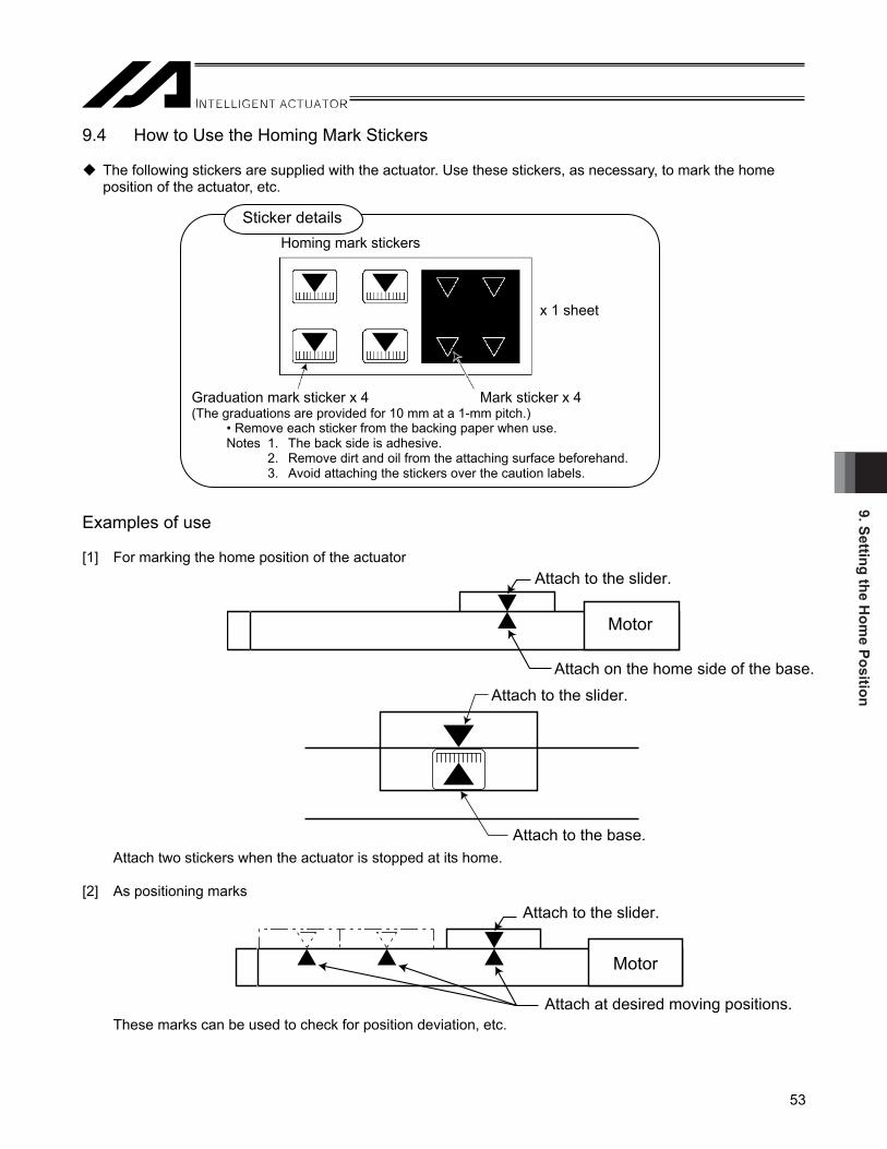
9. Setting the Hom
e Position
53
9.4 How to Use the Homing Mark Stickers
The following stickers are supplied with the actuator. Use these stickers, as necessary, to mark the home position of the actuator, etc.
Examples of use [1] For marking the home position of the actuator
Attach two stickers when the actuator is stopped at its home. [2] As positioning marks
These marks can be used to check for position deviation, etc.
Sticker details
x 1 sheet
Homing mark stickers
Graduation mark sticker x 4 (The graduations are provided for 10 mm at a 1-mm pitch.)
Attach to the slider.
Attach on the home side of the base.
Motor
Mark sticker x 4
• Remove each sticker from the backing paper when use. Notes 1. The back side is adhesive. 2. Remove dirt and oil from the attaching surface beforehand. 3. Avoid attaching the stickers over the caution labels.
Motor
Attach to the slider.
Attach to the slider.
Attach at desired moving positions.
Attach to the base.
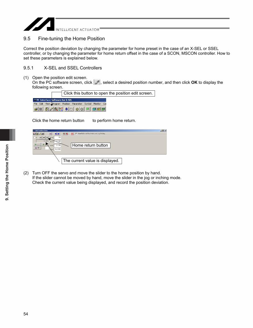
9. S
ettin
g th
e H
ome
Posi
tion
54
9.5 Fine-tuning the Home Position Correct the position deviation by changing the parameter for home preset in the case of an X-SEL or SSEL controller, or by changing the parameter for home return offset in the case of a SCON, MSCON controller. How to set these parameters is explained below. 9.5.1 X-SEL and SSEL Controllers (1) Open the position edit screen.
On the PC software screen, click , select a desired position number, and then click OK to display the following screen.
Click the home return button to perform home return.
(2) Turn OFF the servo and move the slider to the home position by hand.
If the slider cannot be moved by hand, move the slider in the jog or inching mode. Check the current value being displayed, and record the position deviation.
The current value is displayed.
Home return button
Click this button to open the position edit screen.
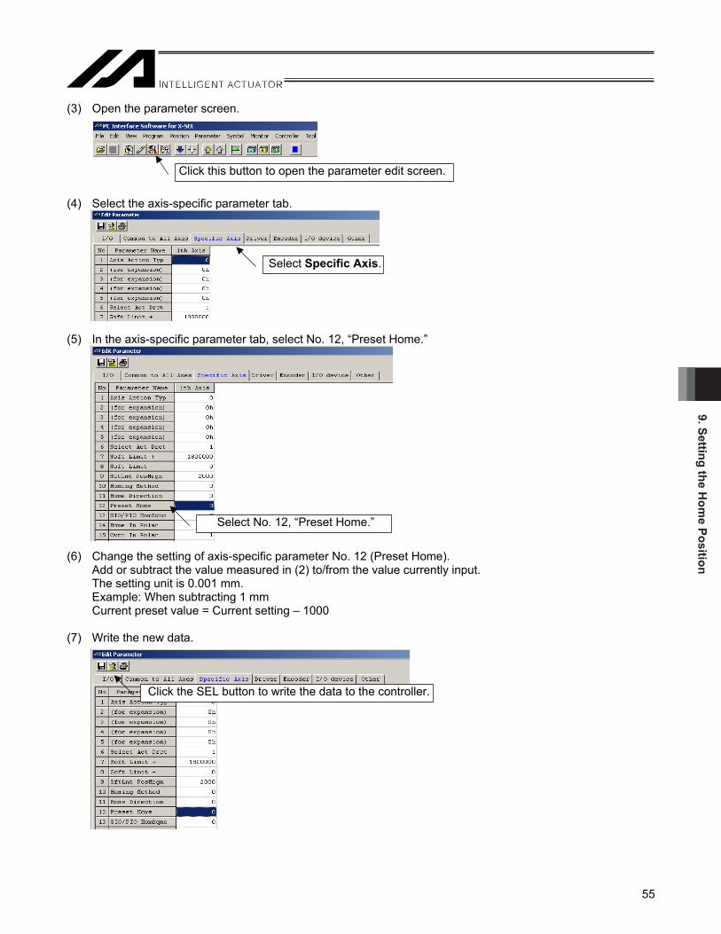
9. Setting the Hom
e Position
55
(3) Open the parameter screen. (4) Select the axis-specific parameter tab. (5) In the axis-specific parameter tab, select No. 12, “Preset Home.” (6) Change the setting of axis-specific parameter No. 12 (Preset Home).
Add or subtract the value measured in (2) to/from the value currently input. The setting unit is 0.001 mm. Example: When subtracting 1 mm Current preset value = Current setting – 1000
(7) Write the new data.
Click this button to open the parameter edit screen.
Select Specific Axis.
Select No. 12, “Preset Home.”
Click the SEL button to write the data to the controller.

9. S
ettin
g th
e H
ome
Posi
tion
56
(8) Transfer the data to the controller. (9) Click OK. (10) Write the data to the flash ROM. (11) Restart the controller.
Select the Parameters check box.
Select Yes.

9. Setting the Hom
e Position
57
9.5.2 ECON, SCON and MSCON Controllers (1) Open the position edit screen.
On the PC software screen, click , select a desired position number, and then click OK to display the following screen.
Click the home return button to perform home return. (2) Turn OFF the servo and move the slider to the home position by hand.
If the slider cannot be moved by hand, move the slider in the jog or inching mode. Check the current value being displayed, and record the position deviation.
Click this button to select the position edit screen.
Home return button
The current value is displayed.

9. S
ettin
g th
e H
ome
Posi
tion
58
(3) Open the parameter screen. (4) The user parameter screen appears. (5) Change user parameter No. 22 (home offset).
* The setting unit is mm. Add or subtract the value measured in (2) to/from the value currently input. Example: When subtracting 0.5 mm Home offset = Current setting – 0.5 mm
Click this button to select the parameter screen.

9. Setting the Hom
e Position
59
(6) Write the new data. Click the controller transfer button, and then click OK. * After the data has been written, turn off the controller power.
Click the controller transfer button.
Click OK.

9. S
ettin
g th
e H
ome
Posi
tion
60
9.6 Absolute Reset Method (Absolute Specification) If the battery has been replaced or encoder cable unplugged following an absolute encoder battery voltage error, etc., absolute reset must be performed. For the method to perform absolute reset, check 1.2, “Related Operation Manuals for Each Controller Supported by This Product” in the operation manual of your controller.

10. Options
61
10. Options 10.1 Brake The brake is a mechanism to retain the slider of a vertically installed actuator so that the slider will not drop when the power is cut off or servo turns off. If any axis is used vertically, an optional brake is required. 10.2 Creep Sensor This sensor is used to perform home return at high speed. Normally home return is implemented with the slider contacting the stopper at the stroke end on the motor side and then reversing its direction. To support this “stopper method,” the home return speed is kept to a range of 10 to 20 mm/s. This means that sliders of long strokes require a longer time to complete the home return. The creep sensor is a proximity sensor that allows the slider to move at high speed until halfway and then reduce its speed to the normal home return speed before the home, in order to shorten the time required for home return. The standard installation position of this sensor is on the right side of the actuator as viewed from the motor, represented by the option model number “C.” A cover similar to the one used for limit switches is provided on the outside of the sensor. If both the creep sensor and limit switches are installed, the same cover is used for each. If you want to have the creep sensor on the left side, specify the option model number “CL.” Check the figure of cover installation in 10.3, “Limit Switch.”
Home return of an axis with a long stroke requires a longer time for the axis to move to the mechanical end.
Creep sensor
A sensor is provided before the mechanical end and once this sensor actuates, the speed is reduced to perform normal home return operation.
Speed
High speedWith creep sensor
Without creep sensor
Creep sensor
Mechanical end
Distance

10. O
ptio
ns
62
21
10.3 Limit Switch Normal home return operation uses the “stopper method” wherein the slider contacts the stopper and reverses, after which the Z-phase is detected and defined as the home. The home limit switch (L) is an option which is designed to perform this reversing operation using a proximity sensor, not a stopper. Use the home limit switch if you want to increase the reliability of home return by, for example, preventing a false detection of mechanical end due to contact with other device, etc. If this option is selected, three proximity sensors are installed, including the home detection sensor (HOME), overtravel sensor on front side (+OT) and overtravel sensor on motor side (-OT). (HOME and -OT are integrated as twin sensors.) Take note that moving the home sensor significantly may shorten the stroke. The standard installation position of the home limit switch and cover is on the right side of the actuator as viewed from the motor, represented by the option model number “L.” If you want to have the limit switch on the right side, specify the option model number “LL.”
Limit switch cover
Limit switch cover Limit switch cover

10. Options
63
10.4 Reversed-home Specification In the reversed-home specification, the home is located on the front side. This is indicated by “NM” in the model number. If you wish to change the home direction after the delivery, consult IAI because the moving direction parameter must be adjusted, as well as the encoder’s Z-phase on certain models. 10.5 Cable Exit Direction The cable should exit in one of the following four 10.6 Guide with Ball Retention Mechanism A spacer (retainer) is inserted between adjacent balls (steel balls) in the guide to reduce noise and achieve smooth operation. This specification is indicated by “RT” in the model number.
There is no longer metal noise generated by colliding balls and thus noise is reduced. Since balls are aligned by retainers, annoying noise decreases. Wear caused by friction between balls decreases, oil no longer runs out due to contact, and lubricating oil collects at the retainers. Accordingly, operation becomes smooth.
Ball
Cable exit from the back on the right
(Option model number: A3E)
Cable exit from the right
(Option model number: A3S)
Cable exit from the back on the left
(Option model number: A1E)
Cable Cable
Cable Cable
Cable exit from the left
(Option model number: A1S)
Ball Spacer (retainer)

10. O
ptio
ns
64
10.7 Master Axis/Slave Axis Specification for Synchronized Operation If the “synchronized operation function” is used, where two actuator axes are operated with the XSEL controller or SSEL controller, one axis is designated as the master axis, while the other axis is designated as the slave axis. The actuators serving as the master axis and slave axis must be of the same specification. The master axis comes with the home limit switch, represented by the option model number “LM.” The standard installation position of the home limit switch and cover is on the right side of the actuator as viewed from the motor. If you want to have the limit switch on the right side, specify the option model number “LLM.”
Controller
Y-axis
X-axis
Master axis (LM) Slave axis (S)
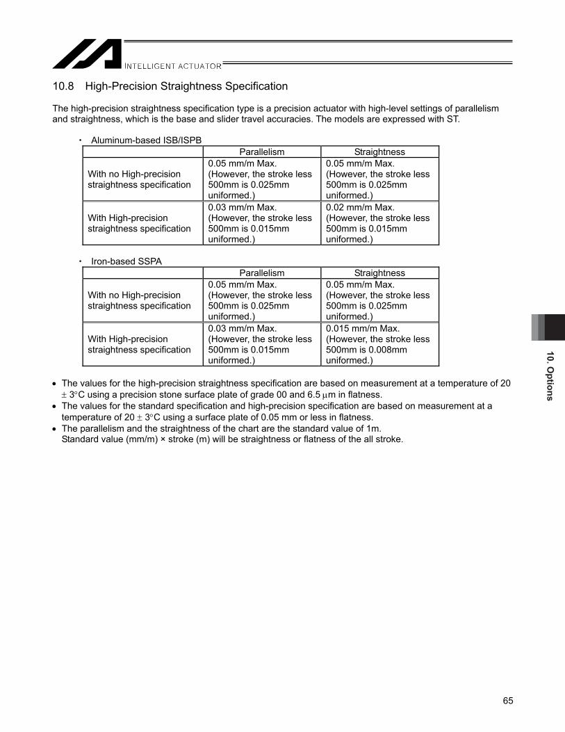
10. Options
65
10.8 High-Precision Straightness Specification The high-precision straightness specification type is a precision actuator with high-level settings of parallelism and straightness, which is the base and slider travel accuracies. The models are expressed with ST.
Aluminum-based ISB/ISPB Parallelism Straightness
With no High-precision straightness specification
0.05 mm/m Max. (However, the stroke less 500mm is 0.025mm uniformed.)
0.05 mm/m Max. (However, the stroke less 500mm is 0.025mm uniformed.)
With High-precision straightness specification
0.03 mm/m Max. (However, the stroke less 500mm is 0.015mm uniformed.)
0.02 mm/m Max. (However, the stroke less 500mm is 0.015mm uniformed.)
Iron-based SSPA
Parallelism Straightness
With no High-precision straightness specification
0.05 mm/m Max. (However, the stroke less 500mm is 0.025mm uniformed.)
0.05 mm/m Max. (However, the stroke less 500mm is 0.025mm uniformed.)
With High-precision straightness specification
0.03 mm/m Max. (However, the stroke less 500mm is 0.015mm uniformed.)
0.015 mm/m Max. (However, the stroke less 500mm is 0.008mm uniformed.)
• The values for the high-precision straightness specification are based on measurement at a temperature of 20 ± 3°C using a precision stone surface plate of grade 00 and 6.5 μm in flatness.
• The values for the standard specification and high-precision specification are based on measurement at a temperature of 20 ± 3°C using a surface plate of 0.05 mm or less in flatness.
• The parallelism and the straightness of the chart are the standard value of 1m. Standard value (mm/m) × stroke (m) will be straightness or flatness of the all stroke.

10. O
ptio
ns
66
Deviation
Measured value
Representative line
Straightness
Slider travel distance
Parallelism
(Reference)
[Measurement Method] [1] Parallelism (horizontal) between the base reference surface and the slider (reference surface)
Affix the base on the surface plate and, with the indicator on the slider contacting a surface running parallel with the two points at both edges of the base reference surface, move the slider over its entire stroke to perform measurement.
[2] Parallelism (vertical) between the base mounting surface and the slider (work part mounting surface)
With the base affixed on the surface plate and indicator on the slider also contacting the surface plate, move the slider over its entire stroke to perform measurement.
[Parallelism and Straightness]
Parallelism is represented by the maximum value on a graph of indicator changes measured by moving the slider over its entire stroke. Straightness, or degree of being straight, is represented by the maximum value among all measured results of parallelism expressed by intervals between two straight lines.
Parallel plane: A plane parallel to the base reference surface (reference point of both ends)
Reference point Reference point

10. Options
67
10.9 Rust prevention film processing The rust prevention film processing is the one that the rust prevention processing (electrolysis rust prevention black film processing) was given to the base reference surface (bottom and the side reference surface) and the slider reference surface (top and the side reference surface). Used to suppress rusts and dusts. Option of SSPA. It is used to suppress the environment. The models are expressed with MD. 10.10 Metal Connector Type The connectors on the motor cable and encoder cable to connect to the actuator change from plastic connectors to metal connectors. The model code is shown as EU.
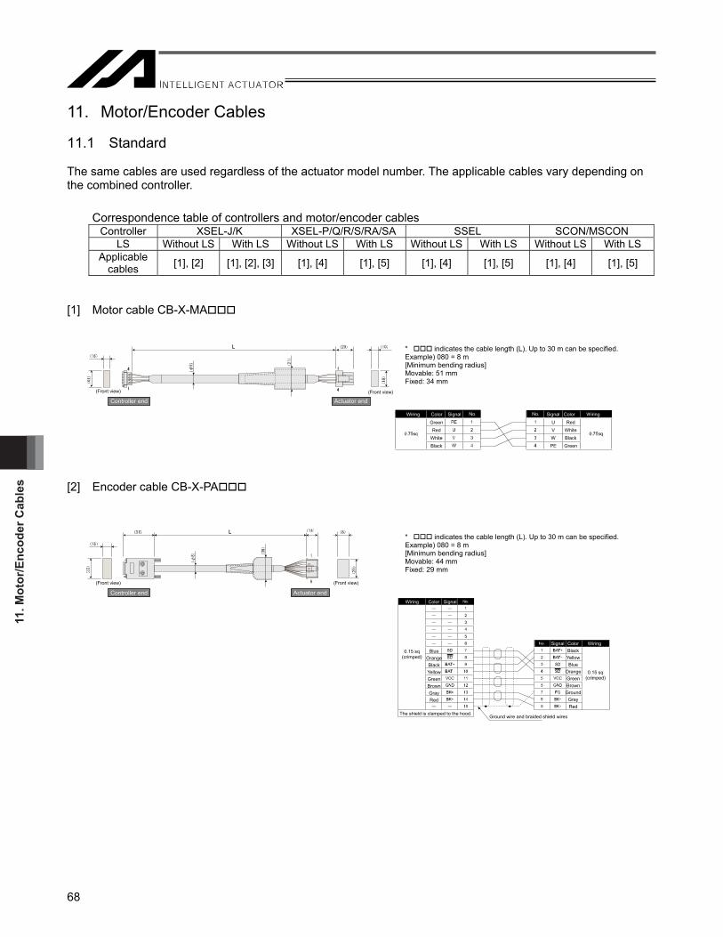
11. M
otor
/Enc
oder
Cab
les
68
11. Motor/Encoder Cables 11.1 Standard The same cables are used regardless of the actuator model number. The applicable cables vary depending on the combined controller.
Correspondence table of controllers and motor/encoder cables Controller XSEL-J/K XSEL-P/Q/R/S/RA/SA SSEL SCON/MSCON
LS Without LS With LS Without LS With LS Without LS With LS Without LS With LS Applicable
cables [1], [2] [1], [2], [3] [1], [4] [1], [5] [1], [4] [1], [5] [1], [4] [1], [5]
[1] Motor cable CB-X-MA [2] Encoder cable CB-X-PA
(Front view)
Controller end (Front view)
Actuator end
* indicates the cable length (L). Up to 30 m can be specified.Example) 080 = 8 m [Minimum bending radius] Movable: 51 mm Fixed: 34 mm
(Front view)
Controller end
(Front view)
Actuator end
* indicates the cable length (L). Up to 30 m can be specified.Example) 080 = 8 m [Minimum bending radius] Movable: 44 mm Fixed: 29 mm
Wiring Color Signal Signal Color Wiring
GreenRed
WhiteBlack
Red White Black Green
No. No.
0.15 sq(crimped)
BlueOrangeBlackYellowGreenBrownGrayRed
Black Yellow Blue
Orange Green Brown Ground
Gray Red
The shield is clamped to the hood.Ground wire and braided shield wires
0.15 sq(crimped)
Wiring Color Signal
Signal Color Wiring
U V W PE

11. Motor/Encoder C
ables
69
[3] Limit switch cable CB-X-LC [4] Encoder cable CB-X1-PA [5] Encoder cable with LS CB-X1-PLA
(Front view)
E24V0VLS
CLEEPOT
RSV
A+AB+BZ+Z
SRD+SRD
BKRBKR+
10111213262524239
181912345678
14151617202122
123456789
No.
No.
E24V0VLS
CLEEPOTRSV
123456
No. Signal Color Wiring
Signal Color Wiring
Wiring Color Signal
The shield is clamped to the hood.Ground wire and braided shield wires
White/blueWhite/yellow
White/redWhite/blackWhite/purpleWhite/gray
Purple Gray
Orange Green Red Black
Ground Blue
Yellow (As for wire color, “White/blue” indicates that
the band is white and insulator is blue.)
AWG26 (soldered)
AWG26 (crimped)
AWG26 (crimped)
Orange Green Purple Gray Red Black Blue
Yellow
White/blueWhite/yellow
White/redWhite/blackWhite/purpleWhite/gray
* indicates the cable length (L). Up to 30 m can be specified. Example) 080 = 8 m [Minimum bending radius] Movable: 33 mm Fixed: 22 mm
* indicates the cable length (L). Up to 30 m can be specified. Example) 080 = 8 m [Minimum bending radius] Movable: 44 mm Fixed: 29 mm
Wiring Color Signal
Signal Color Wiring
AWG26 (soldered)
AWG26 (crimped)
OrangeGreenPurpleGrayRed
BlackBlue
Yellow
BlackYellowBlue
OrangeGreenBrownGround
GrayRed
The shield is clamped to the hood.Ground wire and braided shield wires
(Front view)
Controller end
(Front view)
Actuator end
L
1
6
1
6
(8 )( 12)
)8
1(
)6
φ(
)0
3(
( 12)
(18)
)2
2(
Wiring Color Signal Signal Color WiringSkyblue
PinkLight green
Orange
Gray1B/
skyblue
Note) 1B indicates one black dot mark.
Skyblue
PinkLight green
Orange
Gray1B/
skyblue
(Front view)
Controller end
(Front view)
Actuator end
Plug housing: XMP-09V (JST) Socket contact: BXA—001T-P0.6 (JST) x 9 Retainer: XMS-09V (JST) Note 6: Use the crimper recommended by the connector manufacturer.
Controller end Actuator end
LS end * indicates the cable length (L). Up to 30 m can be specified. Example) 080 = 8 m [Minimum bending radius] Movable: 54 mm Fixed: 36 mm
41 14
13
73
8
81
52
13
14
26
L

11. M
otor
/Enc
oder
Cab
les
70
11.2 Metal Connector Type (Option: Model EU) The same cables are used regardless of the actuator model. The applicable cables vary depending on the models without LS, with LS.
Correspondence table of controllers and motor/encoder cables Controller XSEL-P/Q/R/S/RA/SA, SSEL, SCON, MSCON
LS Without LSApplicable cables [1], [3]
[1] Motor cable CB-XEU-MA□□□
[2] Encoder cable CB-XEU1-PA□□□* □□□indicates the cable length (L). Up to 30m can be specified.
[Minimum bending radius] Movable: 48 mm Fixed: 48 mm
Example) 080 = 8m [Minimum bending radius] Movable: 44 mm Fixed: 29 mm
With LS [1], [2]
* □□□indicates the cable length (L). Up to 30m can be specified. Example) 080 = 8m
GreenRed
WhiteBlack
(crimped)
Wiring Color Signal Signal Color Wiring
Orange
Green
Purple
Gray
Red
Black
Blue
Yellow
OrangeGreen
Red
Black
Purple
Gray
Blue
Yellow
(soldered)
The shield is clamped to the hood.Drain wire and braided shield wires
(soldered)
(As for wire color, “White/blue” indicates that the band is white and insulator is blue.)
The shield is connected to the earth sleeve.
Wiring Color Signal
Signal Color Wiring

11. Motor/Encoder C
ables
71
[3] Encoder cable with LS CB-XEU1-PLA□□□ [Minimum bending radius] Movable: 58 mm Fixed: 33 mm
(soldered)
The shield is clamped to the hood.Drain wire and braided shield wires
(crimped)
(As for wire color, “White/blue” indicates that the band is white and insulator is blue.)
The shield is connected to the earth sleeve.
(crimped)White/blu
White/yellow
White/red White/black White/purple
White/gray
Green Purple Gray Red Black Blue
Yellow
White/bluWhite/yellow
White/red White/black
White/purple White/gray
Orange Green
Red Black Purple Gray
Blue Yellow
Color WiringSignal
* □□□indicates the cable length (L). Up to 30m can be specified. Example) 080 = 8m

12. M
aint
enan
ce/In
spec
tion
72
12. Maintenance/Inspection 12.1 Inspection Items and Intervals Perform maintenance/inspection according to the following timetable. The operating time is assumed to be 8 hours a day. If the actuator is used continuously for 24 hours or the utilization rate is otherwise high, shorten the inspection intervals accordingly.
Period Visual inspection of machine exterior Interior check Grease Supply (Note 1)
At start of operation
After 1 month of operation
After 3 month of operation
After 3 month of operation thereafter
After 6 month of operation (Note 2) Every 6 months thereafter (Note 2)
Period of Grease Supply (reference)
(Note 1) When the actuator is moved back and forth continuously over a distance of 30 mm or less, grease film may disappear. As a guide, move the actuator back and forth over a distance of 50 mm or more for five cycles or so after every 5,000 to 10,000 back-and-forth operations over a short distance. This will restore the oil film.
(Note 2) Check the condition of grease and wipe it off in case it is extremely dirty before supplying new grease. [Period of Grease Supply (reference)] Supply grease in the earlier timing of either the operation distance or months described in the table below.
Period of Grease Supply (reference) Max. Velocity of Use [mm/s] Operation Distance Months 0 to 750 or less 1,250 km
750 to 1500 or less 2,500 km 1500 to 2500 or less 5,000 km
12 months
For the actuators with the guide equipped with the ball retainer (option code RT), implement grease supply in the frequency of the period of grease supply (reference) described in the table below.
Period of Grease Supply (reference) Max. Velocity of Use [mm/s] Operation Distance Months 0 to 750 or less 625 km
750 to 1500 or less 1,250 km 1500 to 2500 or less 2,500 km
6 months
Caution: The grease may be degraded if the actuator has got stored for 6 months or more. Supply grease before starting to use. [Reference to 12.5 Grease Supply]
The speed of grease degradation differs depending on the environment of use (temperature, humidity and ambient environment). It is recommended to shorten the period of grease supply in case of use in bad environment with high temperature, high humidity, high rate of dust and so on. Also, it is recommended to improve the environment in case the color of the grease changes remarkably due to bad environmental condition.

12. Maintenance/Inspection
73
12.2 Visual Inspection of the Machine Exterior Check the following items visually. Main body and work part Loose mounting bolts, etc. Cables Damage to cables, connection of connectors General Noise, vibration 12.3 External Cleaning • Clean the exterior surfaces from time to time. • Wipe off dirt with a soft cloth. • Depending on the situation, base oil of grease may ooze out to the actuator surface. If oil has oozed out, wipe
it off using a soft cloth, etc. • To prevent dust from entering the actuator through gaps and openings, do not clean the actuator by blowing
highly compressed air onto it. • Do not use petroleum-based solvents as they damage plastic parts and painted surfaces. • If the unit gets badly soiled, moisten a soft cloth with a neutral detergent or alcohol and wipe the soiled area
gently.

12. M
aint
enan
ce/In
spec
tion
74
12.4 Interior Check Turn off the power, remove the screw cover and visually inspect the interior. For the interior inspection, check the following items.
Actuator Loosening of actuator mounting bolts, intrusion of dust and other foreign matters
Guide Lubrication condition, soiling, wear, flaking Ball screw Lubrication condition, soiling
Visually check the condition of the interior. Specifically, see if there is any dust or foreign object inside the actuator and also check the condition of lubrication. Even if the grease has turned brown, lubrication is fine as long as the traveling surface appears shiny. If the grease becomes dirty and dull due to dust, or if the grease has worn away due to an extended operating time, lubricate the parts after cleaning them. [The procedure for checking the interior is explained below.] [1] Remove the screw cover using an Allen wrench of 2.5 mm across flats for ISB and ISPB-SXM,
or 3 mm across flats for all other models. [2] Check the interior. [3] When the inspection is complete, tighten the mounting screws for the screw cover. [Cleaning the interior] • Wipe off dirt with a soft cloth. • If constituents of grease have separated and base oil has accumulated on both ends of the guide rail, wipe off
the oil using a soft cloth, etc. If the accumulated oil is not wiped off, it may seep out to the exterior of the actuator.
• To prevent dust from entering the actuator through gaps and openings, do not clean the actuator by blowing highly compressed air onto it.
• Do not use petroleum-based solvents, neutral detergents or alcohol.
Caution: If grease contains a large amount of foreign matter, be sure to wipe off the dirty grease before adding new grease.

12. Maintenance/Inspection
75
Warning: Do not disassemble the front cover because the ball screw is supported by the front cover. If a proper adjustment of the front cover is lost, the shaft center may become offset and the traveling resistance may increase or life of each part may become shorter, or abnormal noises may generate.
An encoder is built into the encoder cover. The encoder not only detects the rotation angle and home signal, but it also performs a critical function in the AC control and the encoder and motor phases have been adjusted precisely. Never touch the encoder.
Caution: Do not forcibly bend or damage the stainless sheet when checking the interior. Any changes to the installation condition cause the sheet to be placed disproportionately on one side and affect the life of the product. In such a case, please contact the IAI Sales Engineering Section. In addition, be sure to wear gloves, etc. when working because the edges of the stainless sheet may cause an injury.

12. M
aint
enan
ce/In
spec
tion
76
12.5 Grease Supply 12.5.1 Applicable Grease [1] For Those other than Lead 36mm of SXM/SXL and Lead 48mm of MXM/MXL/MXMX The following blends of grease are charged before shipment from IAI. Type Parts Factor-set grease Manufacturer ISB, ISPB
SXM/SXL MXM/MXL/MXMX LXM/LXL/LXMX/LXUWX
Guide, ball screw Daphne Eponex Grease No. 2 Idemitsu Kosan
SSPA Guide, ball screw Daphne Eponex Grease No. 2 Idemitsu Kosan ISB, ISPB
LXM/LXMX/LXUWX Intermediate support Daphne Eponex Grease No. 2
(Note 1) Idemitsu Kosan
Note 1 Multemp LRL No. 3 (Kyodo Yushi) can also be applied.
Warning: Never use fluorine grease. Fluorine grease will chemically react with lithium grease and damage the machine.
[2] For Lead 36mm of SXM/SXL and Lead 48mm of MXM/MXL/MXMX Urea based grease is used at the delivery from our factory Type Parts Factor-set grease Manufacturer ISB
SXM/SXL: Lead 36mm MXM/MXL/MXMX: Lead 48mm
Guide, ball screw Multemp ET-R Kyodo Yushi
Warning: Never use lithium grease and fluorine grease. Lithium grease and fluorine grease will
chemically react with urea grease and damage the machine.

12. Maintenance/Inspection
77
12.5.2 Grease Application Method (Note) In case supplying grease from the grease nipple is not possible, follow (2) to supply grease. (1) Grease supply to the guide and ball screw from the grease nipple
A grease nipple is provided on the side of the slider. Grease supply to the guide and ball screw through here. The grease nipple on the right facing from the motor is to grease supply to the guide and ball screw on the right side. The grease nipple on the left facing from the motor is to grease supply to the guide and ball screw on the left. (Grease can be added to the ball screw from either side of the grease nipples.) [1] Apply grease from the left or right grease nipple using a grease gun.
Model Grease Supply (reference) ISB, ISPB SXM/SXL 1.5 cc to 2 cc MXM/MXMX/MXL 3.5 cc to 4 cc LXM/LXMX/LXL 4.5 cc to 5 cc LXUWX 2 cc to 2.5 cc SSPA S 2 cc to 2.5 cc M 5 cc to 5 cc
[2] Rotate the slider several times manually to spread out the grease evenly. Confirm that the ball tracks on the ball screw and guide look glossy with oil of grease. Supply grease
again if it is not spread enough. [3] Wipe off any excess grease.
Caution: Charging too much grease may increase the agitation resistance and cause the ball screw to generate heat easily or allow excess grease on the ball screw to scatter around and dirty the surroundings as the screw turns. Be sure to wipe off excess grease.
It is difficult to move actuators of short leads by hand. With these actuators, do not try to move the actuator by force, but connect a controller and move the actuator by jog operation.

12. M
aint
enan
ce/In
spec
tion
78
Standard grease application opening LXUWX grease application opening
(Note) Follow the grease nipple diameter shown in the list below when preparing a grease gun.
Model Nipple diameter (mm) ISB, ISPB-S φ3.5 ISB, ISPB-M φ6.0 ISB, ISPB-L φ6.0
SSPA-S φ3.5 SSPA-M φ6.0 SSPA-L φ6.0
Grease nipple (Also on the opposite side)Apply grease to the guide and ball screw
Grease nipple Apply grease to the guide and ball screw
Grease nipple (for the guide only)
Grease nipple (left side)

12. Maintenance/Inspection
79
Grease Gun
Attachment Screw R1/8 Maker
(Example) GC-57K Yamada Corporation
Nozzle Maker
N type + Dedicated Nozzle U Type
Connect N type to the tip of the dedicated nozzle U type and attach a grease gun to use.
THK
Caution: In case the grease got into your eye, immediately go to see the doctor to get an appropriate care.After finishing the grease supply work, wash your hands carefully with water and soap to rinse the grease off.
(2) Grease supply to the guide and ball screw in case grease cannot be supplied from grease nipple
[1] Remove the screw cover with using 2.5mm-sized hex wrench for ISB and ISPB-SXM, and 3mm-sized one for other models.
[2] For the guide part, apply grease to the ball sliding area from the gap on the side seal indicated with an arrow with using a grease injector while sliding the slider back and forth to spread the grease. Supply the grease to the guides on both sides. Wipe away the excess grease at last.
Grease Injector
N type Dedicated Nozzle U Type
N type Dedicated Nozzle U Type Attachment Screw R1/8 on Grease Gun Attachment Side

12. M
aint
enan
ce/In
spec
tion
80
[3] Apply the grease on the ball screw with hand after cleaning it, and move the slider back and forth to
spread the grease. Wipe away the excess grease at last.
[4] Once the grease supply is finished, attach the screw cover and tighten the screw.
Caution: Charging too much grease may increase the agitation resistance and cause the ball screw to generate heat easily or allow excess grease on the ball screw to scatter around and dirty the surroundings as the screw turns. Be sure to wipe off excess grease.
It is difficult to move actuators of short leads by hand. With these actuators, do not try to move the actuator by force, but connect a controller and move the actuator by jog operation.
In case the grease got into your eye, immediately go to see the doctor to get an appropriate care. After finishing the grease supply work, wash your hands carefully with water and soap to rinse the grease off.
Side Seal

12. Maintenance/Inspection
81
(3) Grease supply to the intermediate support Applicable models: ISB, ISPB MXMX/LXMX/LXUWX
[Connecting rods] After cleaning the two connecting rods at the intermediate support, apply grease to the rods using a finger. Thereafter, move the slider back and forth to let the grease spread evenly.
[Support bushes] After cleaning the support bushes at both ends of the intermediate support, apply grease to the areas around the bushes using a finger while turning each support bush. Thereafter, move the slider back and forth to let the grease spread evenly.
[Top of slider and intermediate support] After cleaning the top of the slider and top of the intermediate support at both ends, apply grease to these areas using a finger. This is to protect the top of the slider and intermediate support against contact with the screw cover.
Caution: In case the grease got into your eye, immediately go to see the doctor to get an appropriate care.After finishing the grease supply work, wash your hands carefully with water and soap to rinse the grease off.
Connecting rod
Support bush
Top of slider Top of intermediate support

13. R
epla
cing
Inte
rmed
iate
Sup
port
82
13. Replacing Intermediate Support If the intermmediate support needs to be replaced, please contact IAI because it cannot be replaced by a customer.

14. Motor R
eplacement Procedures
83
14. Motor Replacement Procedures The following explains the procedure to replace the motor in the event of coil breakage, etc. Prepare a storage box, etc., and keep in this box, etc., all screws and other parts you have removed to replace the motor, because they will be needed during the reassembly.
Caution: When replacing the motor, you must turn on/off the power and servo to perform the following tasks: [1] Position the coupling on the motor alone [2] Install the motor [3] Operate the brake Exercise due caution when carrying out each task with the power being supplied. The purpose of [1] and [2] is to correlate the motor/encoder and actuator positions. If these tasks are not performed, home return may not be implemented normally. [3] is performed because the brake, which is a non-excitation brake, cannot be released (the slider cannot be moved) without excitation.
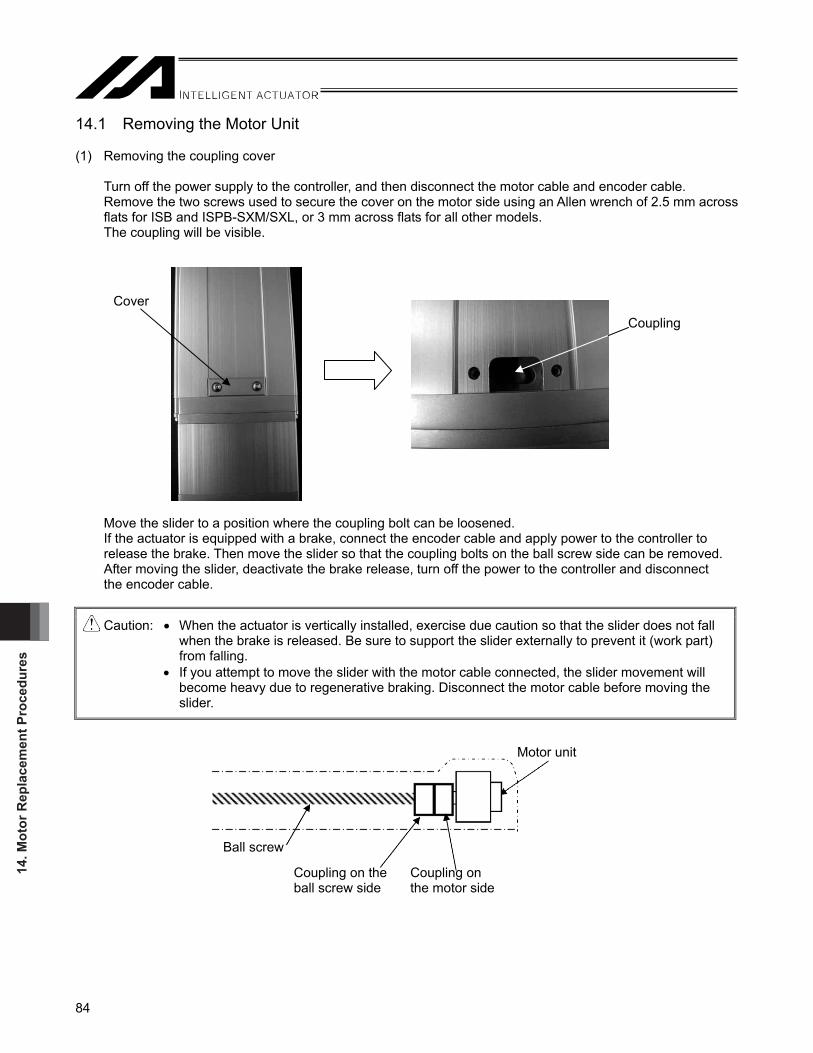
14. M
otor
Rep
lace
men
t Pro
cedu
res
84
Cover
Coupling
14.1 Removing the Motor Unit (1) Removing the coupling cover
Turn off the power supply to the controller, and then disconnect the motor cable and encoder cable. Remove the two screws used to secure the cover on the motor side using an Allen wrench of 2.5 mm across flats for ISB and ISPB-SXM/SXL, or 3 mm across flats for all other models. The coupling will be visible.
Move the slider to a position where the coupling bolt can be loosened. If the actuator is equipped with a brake, connect the encoder cable and apply power to the controller to release the brake. Then move the slider so that the coupling bolts on the ball screw side can be removed. After moving the slider, deactivate the brake release, turn off the power to the controller and disconnect the encoder cable.
Caution: • When the actuator is vertically installed, exercise due caution so that the slider does not fall when the brake is released. Be sure to support the slider externally to prevent it (work part) from falling.
• If you attempt to move the slider with the motor cable connected, the slider movement will become heavy due to regenerative braking. Disconnect the motor cable before moving the slider.
Ball screw
Coupling on the ball screw side
Coupling on the motor side
Motor unit

14. Motor R
eplacement Procedures
85
Rear cover
Rear cover Cable mounting cover
Rear cover
(2) Removing the rear cover [1] Remove the screws used to secure the cable mounting cover using an Allen wrench of 2 mm across flats. [2] Remove the four bolts used to secure the rear cover using an Allen wrench of 2.5 mm across flats for ISB
and ISPB-SXM/SXL, or 3 mm across flats for all other models. [3] Slide the cable affixing cover to remove it from the rear cover. Cable affixing cover

14. M
otor
Rep
lace
men
t Pro
cedu
res
86
Cable mounting cover
(3) Connector Disconnection inside Motor Cover There are motor cables and actuator cables joined with a connector inside the motor cover. Disconnect the connectors. Proceed to Step (4) for those not connected with a connector.
Before disconnecting connectors After disconnecting connectors
(4) Removing the cable mounting cover
(Note) It is not necessary to have this work process for the motor equipped with a brake connected with a
connector inside the motor cover. Do not detach the cable fixing cover.
Remove the three bolts used to secure the cable mounting cover to the cable using an Allen wrench of 2.5 mm across flats.
(Note) After the motor is replaced, the motor cables must be installed on the cable affixing cover. Before
removing the affixing cover, mark the cables so that their installation positions can be checked later on.

14. Motor R
eplacement Procedures
87
(5) Removing the motor cover
Remove the two bolts used to secure the motor cover using an Allen wrench of 2.5 mm across flats for ISB and ISPB-SXM/SXL, or 3 mm across flats for all other models Two of these bolts are found below the motor at locations further back in the motor cover.
The unit will look like below after the motor cover is removed.
Motor Motor cover Bolts affixing the motor cover

14. M
otor
Rep
lace
men
t Pro
cedu
res
88
(6) Removing the motor unit [1] Loosen the coupling tightening bolt.
Caution: If the actuator is installed vertically, exercise due caution not to let the slider drop. Hold the slider (work part) from the outside to prevent it from dropping, and then loosen the coupling bolt.
Remove the bolts used to secure the motor using an Allen wrench of 4 mm across flats, and pull out the
motor unit and coupling from the motor housing.
Motor affixing bolt Motor affixing bolt
Motor affixing bolt Motor affixing bolt
Motor
Body
Motor
With connector inside motor cover
No connector inside motor cover

14. Motor R
eplacement Procedures
89
14.2 Installing a Replacement Motor (1) Replacement Motor Unit
The replacement motor will be supplied together with the coupling installed as shown below.
Caution: The motor actuator cable exit direction varies depending on the actuator cable exit direction. The cable exit direction must be the same for the motor to be removed and replacement motor to be installed. If the cable exit direction is different on the installed motor, deviation of the home position will occur. Align the home mark on the motor with the slit position on the coupling, and then install the motor/coupling into the actuator. Never loosen the coupling on the motor side. The slit in the coupling is provided to help correlate the actuator and encoder positions. If the coupling is loosened, home return may not achieve a normal home position.
(2) Aligning the slider position [1] Use extension cables (motor/encoder cables) to connect the motor cable and the encoder cable of the motor
unit to the controller.
Slit
Home mark

14. M
otor
Rep
lace
men
t Pro
cedu
res
90
[2] Action to be taken upon error • With XSEL or SSEL controller, if the 7-segment display on the front face of the controller does not show
“rdy” or “Ardy” but indicates an alarm after turning on the power, reset the alarm by checking the operation manual. If the problem cannot be resolved, contact IAI.
The 7-segment display shows “Erg”: Cancel the emergency stop. The 7-segment display shows “ECA1”: Perform absolute reset.
• With the SCON controller, if the PWR LED indicator on the front panel of the controller does not come on, but the ALM indicator comes on instead, after turning on the power, connect the PC or teaching pendant to check the nature of the alarm. Reset the alarm by checking the operation manual. If the problem cannot be resolved, contact IAI. Alarm code “0EE”: Perform absolute reset.
[3] Adjusting the slider position
Place a spacer (jig or block gauge) having a specified thickness between the mechanical end of the home position and the slider, and then press them firmly against one another so as not to allow for gaps. If the actuator is equipped with a brake, apply power to the controller to release the brake before moving the slider. After moving the slider, deactivate the brake release, turn off the power to the controller and disconnect the brake lead line connector. The thickness of the spacer will differ according to the home offset distance, the SE (stroke end) to ME (mechanical end) distance and the actuator type. (See Attachment 1 on Page 83.) If the actuator is of reversed home specification, see Attachment 2 on Page 84.
7-segment display
LED display
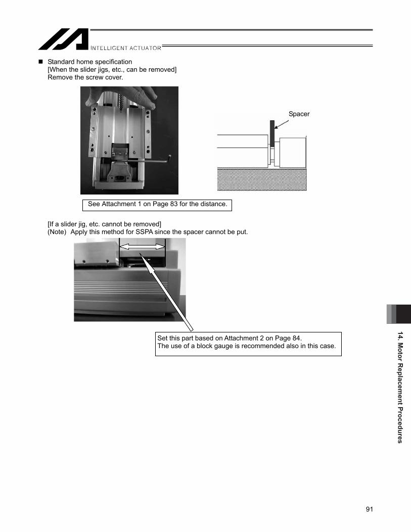
14. Motor R
eplacement Procedures
91
Standard home specification [When the slider jigs, etc., can be removed] Remove the screw cover.
[If a slider jig, etc. cannot be removed]
(Note) Apply this method for SSPA since the spacer cannot be put.
Set this part based on Attachment 2 on Page 84. The use of a block gauge is recommended also in this case.
Spacer
See Attachment 1 on Page 83 for the distance.

14. M
otor
Rep
lace
men
t Pro
cedu
res
92
Reversed home specification [When the jigs on the slider can be removed] Remove the screw cover.
[If a slider jig, etc. cannot be removed] (Note) Apply this method for SSPA since the spacer cannot be put.
Spacer
Set this part based on Attachment 2 on Page 84. The use of a block gauge is recommended also in this case.
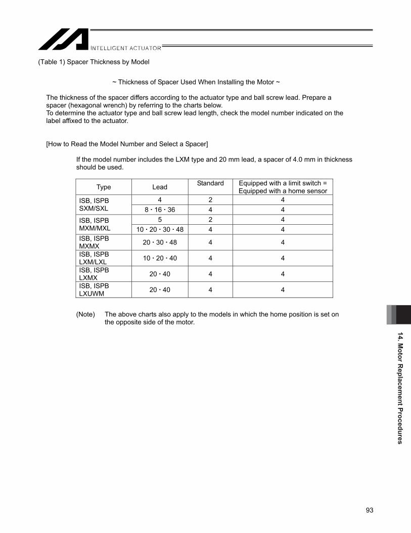
14. Motor R
eplacement Procedures
93
(Table 1) Spacer Thickness by Model
~ Thickness of Spacer Used When Installing the Motor ~
The thickness of the spacer differs according to the actuator type and ball screw lead. Prepare a spacer (hexagonal wrench) by referring to the charts below. To determine the actuator type and ball screw lead length, check the model number indicated on the label affixed to the actuator.
[How to Read the Model Number and Select a Spacer]
If the model number includes the LXM type and 20 mm lead, a spacer of 4.0 mm in thickness should be used.
(Note) The above charts also apply to the models in which the home position is set on the opposite side of the motor.
Type Lead Standard Equipped with a limit switch = Equipped with a home sensor
4 2 4 ISB, ISPB SXM/SXL 8 16 36 4 4
5 2 4 ISB, ISPB MXM/MXL 10 20 30 48 4 4 ISB, ISPB MXMX 20 30 48 4 4
ISB, ISPB LXM/LXL 10 20 40 4 4
ISB, ISPB LXMX 20 40 4 4
ISB, ISPB LXUWM 20 40 4 4

14. M
otor
Rep
lace
men
t Pro
cedu
res
94
(Table 2) Dimension Table by Model Standard home specification
Adjust dimension to: [mm] Type Lead Standard Equipped with a limit switch =
Equipped with a home sensor 4 35 37 ISB, ISPB
SXM/SXL 8 16 36 37 37 5 49 51 ISB, ISPB
MXM/MXL 10 20 30 48 51 51 ISB, ISPB MXMX 20 30 48 99 99
ISB, ISPB LXM/LXL 10 20 40 54 54
ISB, ISPB LXMX 20 40 106 106
ISB, ISPB LXUWM 20 40 106 106
SSPA SXM 10 20 30 24 24
SSPA MXM 10 20 40 28 28
SSPA LXM 25 50 32 32
Reversed home specification
Adjust dimension to: [mm] Type Lead Standard Equipped with a limit switch =
Equipped with a home sensor 4 20 22 ISB, ISPB
SXM 8 16 36 22 22 5 29 31 ISB, ISPB
MXM 10 20 30 48 31 31 ISB, ISPB MXMX 20 30 48 79 79
ISB, ISPB LXM 10 20 40 32 32
ISB, ISPB LXMX 20 40 78 78
ISB, ISPB LXUWM 20 40 78 78
SSPA SXM 10 20 30 24 24
SSPA MXM 10 20 40 28 28
SSPA LXM 25 50 32 32

14. Motor R
eplacement Procedures
95
(3) Aligning the motor position Apply power to the controller, and then run the motor with the jog control using the PC software or teaching pendant to align the home mark on the motor with the slit position on the coupling. (Jog at 1 mm per second (minimum speed).)
* In certain situations such as when the controller is away from the motor, you can turn on the servo after
aligning the coupling and slit positions by hand.
Caution: Align the home mark on the motor with the slit position on the coupling, and then install the motor/coupling into the actuator. Never loosen the coupling on the motor side. The slit in the coupling is provided to help correlate the actuator and encoder positions. If the coupling is loosened, home return may not achieve a normal home position.
Slit Slit position
Home mark Home mark

14. M
otor
Rep
lace
men
t Pro
cedu
res
96
(4) Installing the motor temporarily [1] With the servo kept on in the replacement motor, fit the coupling on the motor unit to the groove on the ball
screw axis, and temporarily tighten the motor housing and replacement motor. (Tighten manually for this temporary purpose.) When fastening the replacement motor and motor housing temporarily, be sure to place them next to each other with no gaps or play. If the cable exits from the right, install the motor as shown in the photograph below so that the motor cable is positioned on the left side. If the cable exits from the left, install the replacement motor in the position opposite of the photograph.
Caution: The cable exit direction must be the same for the motor to be removed and replacement motor to be installed. If the cable exit direction is different on the installed motor, deviation of the home position will occur.
Type Bolt used
ISB, ISPB SXM/SXL M4 x 12
ISB, ISPB MXM/MXL/ MXMX LXM/LXL/LXMX/ LXUWM
M5 x 15
SSPA SXM M5 x 15
SSPA MXM M5 x 15
SSPA LXM M6 x 20
Four bolts used to secure the motor

14. Motor R
eplacement Procedures
97
[2] With the motor fastened temporarily, tighten the coupling bolts on the ball screw side. [3] Turn off the power to the controller, disconnect all connectors (including the motor cable and encoder cable
connectors), but this time tighten the bolts in place to the specified torque.
<Tightening torques by coupling bolt type>
Type Tightening torque ISB, ISPB SXM/SXL 2.0 N m
ISB, ISPB MXM/MXL/ MXMX
2.0 N m
ISB, ISPB LXM/LXL/LXMX/ LXUWM
4.0 N m
SSPA SXM 2.0 N m
SSPA MXM 4.0 N m
SSPA LXM 7.0 N m

14. M
otor
Rep
lace
men
t Pro
cedu
res
98
(5) Centering and securing the motor unit Loosen the motor affixing screws you have tightened only loosely in an earlier step, move the slider back and forth by hand for three to four cycles (over as long an operation stroke as possible) and eventually move the slider to near the mechanical end on the motor side and find a position at which the motor vibration becomes the smallest. Affix the motor unit in the motor housing at this position.
<Tightening torque of the bolt when motor is affixed>
(Note) If the actuator is equipped with a brake, connect the encoder cable of the motor unit to the controller
using the extension cables (motor and encoder cables), and apply power to the controller. Then release the brake and move the slider. For safety reasons, after securing the motor unit, deactivate the brake release, turn off the power to the controller and disconnect the cable connectors from the motor unit.
Type Bolt used Tightening torque
ISB, ISPB SXM/SXL M4 x 12 176 N cm
ISB, ISPB MXM/MXL/ MXMX LXM/LXL/LXMX/ LXUWM
M5 x 15 342 N cm
SSPA SXM M5 x 15 342 N cm
SSPA MXM M5 x 15 342 N cm
SSPA LXM M6 x 20 536 N cm

14. Motor R
eplacement Procedures
99
(6) Installing the motor cover Tighten the two bolts to install the motor cover using an Allen wrench of 2.5 mm across flats for ISB and ISPB-SXM/SXL, or 3 mm across flats for all other models. Two of these bolts are found below the motor at locations further back in the motor cover.
Motor Motor cover Bolts affixing the motor cove

14. M
otor
Rep
lace
men
t Pro
cedu
res
100
(7) Connection of Connectors inside Motor Cover For the motor with a connector inside the motor cover, connect to the actuator cables with a connector. For other process, proceed to Step (8).
Before disconnecting connectors After disconnecting connectors
Store the connector in the motor cover as shown in the figure below. Pay attention not to pinch the cables on the motor cover or end cover when storing the cables.
ISB-S
ISB-M
ISB-L
SSPA-S

14. Motor R
eplacement Procedures
101
Cable mounting cover
(8) Installing the cable mounting cover (Note) It is not necessary to have this work process when the connection is made with connectors inside
the motor cover. Tighten the three bolts using an Allen wrench of 2.5 mm across flats to install the cable mounting cover to the cable. Install the cable mounting cover in roughly the same position as the area marked on the motor that has been removed. The cable mounting cover is imprinted with M and PG. Clamp the motor cable to the M side, and the encoder cable to the PG side. (Note) After the motor is replaced, install the cable mounting cover in roughly the same position as the
replaced motor. Mark the cable for the motor to be replaced so that the installation position can be identified.

14. M
otor
Rep
lace
men
t Pro
cedu
res
102
Rear cover
Cable mounting cover
(9) Installing the rear cover [1] Slide the rear cover and insert it into the cable mounting cover. [2] Tighten the four bolts to install the rear cover using an Allen wrench of 2.5 mm across flats for ISB and
ISPB-SXM/SXL, or 3 mm across flats for all other models. [3] Tighten the screws with an Allen wrench of 2 mm across flats to attach the screws for the cable mounting
cover.
Rear cover
Cable mounting cover
Rear cover
Cable mounting cover

14. Motor R
eplacement Procedures
103
(10) Installing the coupling cover
Tighten the two screws to install the cover on the motor side using an Allen wrench of 2.5 mm across flats for ISB and ISPB-SXM/SXL, or 3 mm across flats for all other models.
Coupling coverCoupling

14. M
otor
Rep
lace
men
t Pro
cedu
res
104
14.3 Correcting for Position Deviation (1) Connect the motor cable and encoder cable and turn on the controller power. (2) Use the PC software or teaching pendant to perform homing and check the home position.
Repeat homing several times to confirm that the actuator returns to the same position. (If the actuator is of absolute specification, perform an absolute reset.)
(3) Check the amount of position deviation.
The position may have changed slightly from where it was before the motor was replaced. Accordingly, select a desired position number that allows you to check the amount of deviation before and after the replacement, and then perform positioning to that position and measure the amount of deviation.
(4) Reflect the deviation in the home preset parameter in the case of an X-SEL/SSEL controller, or in the home
return offset parameter in the case of an SCON, MSCON controller. [For the setting method, refer to 9.5, “Fine-tuning the Home Position.”]
* If the two positions differ significantly (one ball screw revolution or more = lead or more) or if the actuator does
not return to the same position when homing is repeated, install the motor unit again by following the procedure described in this manual. When the motor unit was installed, a wrong spacer size may have been used or the slider may have moved instead of remaining stationary at the mechanical end.
14.4 Operation Check after Replacing the Motor After replacing the motor, perform continuous operation to confirm absence of vibration or abnormal noise.

15. Appendix
105
15. Appendix 15.1 External Dimensions 15.1.1 ISB, ISPB-SXM
A
5
23
51814
L
389010
41
14MESEME
8490
10081
651
26
T
77
952
1
0920.009
45
5
70 101090
803590
0720.0
B50
8
G
K5020
487
0771
0524
F50
60+
210.0
D
J
3.43.7
1.5 4.5
651
7
11
5
Base mounting holes and T slot details
2- 6 H7, depth 10
Base reference surface
Home
Base reference surface
Slider reference surface
2-M3 depth 6 (Same on the opposite side)
Grease application nipple (Same on the opposite side)
2- 6 H7, depth 10
2- 6 H7, depth 10
P-M6, depth 16
4-M6, depth 18
7 (from the reference surface)Oblong, depth 10
E- 7 hole, 11 counterbore
Cx200 pitch
Hx200 pitch
149 (standard + 31.5: Lead 36 mm)124 (standard + 20) (WA: Except for Lead 36 mm)104 (standard + 35) (I, A)
Specification with a brake
Cable exit from the back on the right
Cable exit from the right
Cable exit from the left
Washer assembled screw M3(For FG at two locations)
T slot
(from the opposite side)
φ
Without brake117.5 (WA: Lead 36 mm)104 (WA: Except for Lead 36 mm)69 (I, A)
WA : Battery-less Absolute I : Incremental A : Absolute
ME : Mechanical End SE : Stroke End
* It is only ISB which has 100W and Lead 36mm.

15. A
ppen
dix
106
L
Battery-less Absolute Mass [kg]
Incremental Absolute Except for
Lead 36mm Lead
36mm Except for
Lead 36mmLead
36mm Stroke
Stand- ard
with Brake
Stand- ard
with Brake
Stand- ard
with Brake
A B C D E F G H J K P
Stand- ard
with Brake
Stand-ard
with Brake
100 344 379 379 399 392.5 424 100 251 0 151 4 151 131 0 56 0 8 3.0 3.3 3.2 3.5150 394 429 429 449 442.5 474 150 301 0 201 4 201 131 0 56 50 10 3.4 3.7 3.6 3.9200 444 479 479 499 492.5 524 200 351 0 251 4 251 181 0 106 50 10 3.8 4.1 4.0 4.3250 494 529 529 549 542.5 574 250 401 1 101 6 301 231 0 156 50 10 4.2 4.5 4.3 4.6300 544 579 579 599 592.5 624 300 451 1 151 6 351 281 0 206 50 10 4.5 4.8 4.7 5.0350 594 629 629 649 642.5 674 350 501 1 201 6 401 331 0 256 50 10 4.9 5.2 5.0 5.3400 644 679 679 699 692.5 724 400 551 1 251 6 451 381 1 106 50 12 5.2 5.5 5.4 5.7450 694 729 729 749 742.5 774 450 601 2 101 8 501 431 1 156 50 12 5.6 5.9 5.7 6.0500 744 779 779 799 792.5 824 500 651 2 151 8 551 481 1 206 50 12 5.9 6.2 6.1 6.4550 794 829 829 849 842.5 874 550 701 2 201 8 601 531 1 256 50 12 6.3 6.6 6.5 6.8600 844 879 879 899 892.5 924 600 751 2 251 8 651 581 2 106 50 14 6.6 6.9 6.8 7.1650 894 929 929 949 942.5 974 650 801 3 101 10 701 631 2 156 50 14 7.0 7.3 7.2 7.5700 944 979 979 999 992.5 1024 700 851 3 151 10 751 681 2 206 50 14 7.3 7.6 7.5 7.8750 994 1029 1029 1049 1042.5 1074 750 901 3 201 10 801 731 2 256 50 14 7.7 8.0 7.9 8.2800 1044 1079 1079 1099 1092.5 1124 800 951 3 251 10 851 781 3 106 50 16 8.0 8.3 8.2 8.5850 1094 1129 1129 1149 1142.5 1174 850 1001 4 101 12 901 831 3 156 50 16 8.4 8.7 8.6 8.9900 1144 1179 1179 1199 1192.5 1224 900 1051 4 151 12 951 881 3 206 50 16 8.7 9.0 8.9 9.2
Stroke can be indicated from 950 to 1100 for Lead 36mm.
L
Battery-less Absolute
Mass [kg]
Lead 36mm Lead 36mmStroke
Stand- ard
with Brake
A B C D E F G H J K P
Stand-ard
with Brake
950 1242.5 1274 950 1101 4 201 12 1001 931 3 256 50 16 9.3 9.61000 1292.5 1324 1000 1151 4 251 12 1051 981 4 106 50 18 9.7 10.01050 1342.5 1374 1050 1201 5 101 14 1101 1031 4 156 50 18 10.0 10.31100 1392.5 1424 1100 1251 5 151 14 1151 1081 4 206 50 18 10.4 10.7

15. Appendix
107
15.1.2 ISB, ISPB-SXL * It is only ISB which has 100W and Lead 36mm.
A
5
23
52814
L
3811010
41
14MESEME
8490
10081
651
26
77
952
1
0920.0
55
5
70 2020
110
09
51005
803590
0720.0
B50
8
G
505020
487
0771
0524
F50
60+
210.0
D
J
3.43.7
1.5 4.5
651
7
11
5
Base mounting holes and T slot details
2- 6 H7, depth 10
Base reference surface
Home
Base reference surface
Slider reference surface
2-M3 depth 6 (Same on the opposite side)
Grease application nipple (Same on the opposite side)
2- 6 H7, depth 10
2- 6 H7, depth 10
P-M6, depth 16
8-M6, depth 18
7 (from the reference surface)Oblong, depth 10
E- 7 hole, 11 counterbore(from the opposite side)
Cx200 pitch
Hx200 pitch
Specification with a brake
Cable exit from the back on the right
Cable exit from the right
Cable exit from the left
Washer assembled screw M3(For FG at two locations)
T slot
149 (standard + 31.5: Lead 36 mm)124 (standard + 20) (WA: Except for Lead 36 mm)104 (standard + 35) (I, A)
Without brake117.5 (WA: Lead 36 mm)104 (WA: Except for Lead 36 mm)69 (I, A)
WA : Battery-less Absolute I : Incremental A : Absolute
ME : Mechanical End SE : Stroke End

15. A
ppen
dix
108
L
Battery-less Absolute Mass [kg]
Incremental Absolute Except for
Lead 36mm Lead
36mm Except for
Lead 36mmLead
36mm Stroke
Stand- ard
with Brake
Stand- ard
with Brake
Stand- ard
with Brake
A B C D E F G H J P
Stand- ard
with Brake
Stand-ard
with Brake
130 394 429 429 449 442.5 474 130 301 0 201 4 201 131 0 56 10 3.1 3.4 3.7 4.0180 444 479 479 499 492.5 524 180 351 0 251 4 251 181 0 106 10 3.5 3.8 4.1 4.4230 494 529 529 549 542.5 574 230 401 1 101 6 301 231 0 156 10 3.9 4.2 4.4 4.7280 544 579 579 599 592.5 624 280 451 1 151 6 351 281 0 206 10 4.3 4.5 4.8 5.1330 594 629 629 649 642.5 674 330 501 1 201 6 401 331 0 256 10 4.6 4.9 5.1 5.4380 644 679 679 699 692.5 724 380 551 1 251 6 451 381 1 106 12 5.0 5.3 5.5 5.8430 694 729 729 749 742.5 774 430 601 2 101 8 501 431 1 156 12 5.3 5.6 5.8 6.1480 744 779 779 799 792.5 824 480 651 2 151 8 551 481 1 206 12 5.7 6.0 6.2 6.5530 794 829 829 849 842.5 874 530 701 2 201 8 601 531 1 256 12 6.0 6.3 6.6 6.9580 844 879 879 899 892.5 924 580 751 2 251 8 651 581 2 106 14 6.4 6.7 6.9 7.2630 894 929 929 949 942.5 974 630 801 3 101 10 701 631 2 156 14 6.7 7.0 7.3 7.6680 944 979 979 999 992.5 1024 680 851 3 151 10 751 681 2 206 14 7.1 7.4 7.6 7.9730 994 1029 1029 1049 1042.5 1074 730 901 3 201 10 801 731 2 256 14 7.4 7.7 8.0 8.3780 1044 1079 1079 1099 1092.5 1124 780 951 3 251 10 851 781 3 106 16 7.8 8.1 8.3 8.6830 1094 1129 1129 1149 1142.5 1174 830 1001 4 101 12 901 831 3 156 16 8.1 8.4 8.7 9.0880 1144 1179 1179 1199 1192.5 1224 880 1051 4 151 12 951 881 3 206 16 8.5 8.8 9.0 9.3
Stroke can be indicated from 930 to 1080 for Lead 36mm.
L
Battery-less Absolute
Mass [kg]
Lead 36mm Lead 36mmStroke
Stand- ard
with Brake
A B C D E F G H J P
Stand-ard
with Brake
930 1242.5 1274 930 1101 4 201 12 1001 931 3 256 16 9.4 9.7980 1292.5 1324 980 1151 4 251 12 1051 981 4 106 18 9.8 10.1
1030 1342.5 1374 1030 1201 5 101 14 1101 1031 4 156 18 10.1 10.41080 1392.5 1424 1080 1251 5 151 14 1151 1081 4 206 18 10.5 10.8

15. Appendix
109
15.1.3 ISB, ISPB-MXM * It is only ISB which has 400W and Lead 48mm.
5
A32
5824
91
120 5212 14
L
MESEME
110
120
134106
622
08
102
177
2
7021
20.0021
607090
2515
2515
120
100
50F
G
40120J505020
D50
07090102
55
0920.0
B
011
80
510.0+
10
9
7
3.43.7
1.5 4.5
622
16
Base mounting holes and T slot details
2- 8 H7, depth 10
Base reference surface
Home
400W: 138 (WA)100W: 87 (WA)200W: 113 (WA)100W: 63 (I, A)200W: 78 (I, A)
Base reference surface
Slider reference surface
2-M3 depth 6 (Same on the opposite side)
Grease application nipple (Same on the opposite side)2- 8 H7, depth 10
2- 8 H7, depth 10
K-M8, depth 20
4-M6, depth 18
10 (from the reference surface)Oblong, depth 10
E- 9 hole, 16 counterbore(from the opposite side)
Cx200 pitch
Hx200 pitch
Specification with a brake
Cable exit from the back on the right
Cable exit from the right
Cable exit from the left
4-M6, depth 18
Washer assembled screw M3(For FG at two locations)
T slot
400W: 173 (Standard + 35) (WA)100W: 113 (Standard + 26) (WA)200W: 138 (Standard + 25) (WA)100W: 87 (Standard + 24) (I, A)200W: 113 (Standard + 35) (I, A)
WA : Battery-less Absolute I : Incremental A : Absolute
ME : Mechanical End SE : Stroke End

15. A
ppen
dix
110
L
Incremental Absolute Battery-less Absolute
Mass [kg]
Standard 100W 200W 400W Stroke
100W 200W 100W 200W 400W
A B C D E F G H J K
Stand- ard
with Brake
Stand- ard
with Brake
Stand-ard
with Brake
100 393 408 417 443 468 100 304 0 204 4 204 134 0 24 10 6.0 6.5 6.4 7.0 7.0 7.6150 443 458 467 493 518 150 354 0 254 4 254 184 0 74 10 6.6 7.1 7.1 7.7 7.6 8.2200 493 508 517 543 568 200 404 1 104 6 304 234 0 124 10 7.2 7.7 7.7 8.3 8.3 8.9250 543 558 567 593 618 250 454 1 154 6 354 284 0 174 10 7.9 8.4 8.4 9.0 8.9 9.5300 593 608 617 643 668 300 504 1 204 6 404 334 0 224 10 8.5 9.0 9.0 9.6 9.5 10.1350 643 658 667 693 718 350 554 1 254 6 454 384 0 274 10 9.2 9.7 9.6 10.2 10.2 10.8400 693 708 717 743 768 400 604 2 104 8 504 434 1 124 12 9.8 10.3 10.2 10.8 10.8 11.4450 743 758 767 793 818 450 654 2 154 8 554 484 1 174 12 10.4 10.9 10.9 11.5 11.4 12.0500 793 808 817 843 868 500 704 2 204 8 604 534 1 224 12 11.0 11.5 11.5 12.1 12.1 12.7550 843 858 867 893 918 550 754 2 254 8 654 584 1 274 12 11.7 12.2 12.2 12.8 12.7 13.3600 893 908 917 943 968 600 804 3 104 10 704 634 2 124 14 12.3 12.8 12.8 13.4 13.3 13.9650 943 958 967 993 1018 650 854 3 154 10 754 684 2 174 14 13.0 13.5 13.4 14.0 14.0 14.6700 993 1008 1017 1043 1068 700 904 3 204 10 804 734 2 224 14 13.6 14.1 14.0 14.6 14.6 15.2750 1043 1058 1067 1093 1118 750 954 3 254 10 854 784 2 274 14 14.2 14.7 14.7 15.3 15.2 15.8800 1093 1108 1117 1143 1168 800 1004 4 104 12 904 834 3 124 16 14.8 15.3 15.3 15.9 15.9 16.5850 1143 1158 1167 1193 1218 850 1054 4 154 12 954 884 3 174 16 15.5 16.0 16.0 16.6 16.5 17.1900 1193 1208 1217 1243 1268 900 1104 4 204 12 1004 934 3 224 16 16.1 16.6 16.6 17.2 17.2 17.7950 1243 1258 1267 1293 1318 950 1154 4 254 12 1054 984 3 274 16 16.8 17.3 17.3 17.9 17.8 18.4
1000 1293 1308 1317 1343 1368 1000 1204 5 104 14 1104 1034 4 124 18 17.4 17.9 17.9 18.5 18.4 19.01050 1343 1358 1367 1393 1418 1050 1254 5 154 14 1154 1084 4 174 18 18.1 18.6 18.5 19.1 19.1 19.61100 1393 1408 1417 1443 1468 1100 1304 5 204 14 1204 1134 4 224 18 18.7 19.2 19.1 19.7 19.7 20.3 Stroke can be indicated from 1150 to 1300 for 400W, Lead 48mm.
L Mass [kg]Battery-less
Absolute 400W
Standard Stroke
400W
A B C D E F G H J KStand-
ardwith
Brake
1150 1518 1150 1354 5 254 14 1254 1184 4 274 18 20.3 20.91200 1568 1200 1404 6 104 16 1304 1234 5 124 20 21.0 21.61250 1618 1250 1454 6 154 16 1354 1284 5 174 20 21.6 22.21300 1668 1300 1504 6 204 16 1404 1334 5 224 20 22.2 22.8

15. Appendix
111
15.1.4 ISB, ISPB-MXL * It is only ISB which has 400W and Lead 48mm.
5
A32
52324
91
150 5212 14
L
MESEME
110
120
134106
622
08
102
177
2
7021
20.0±
021
75
120 1515150
309030
100
50F
G
40120J505020
D50
07090102
55
0920.0±
B
011
80
510.0+
10
9
7
3.43.7
1.5 4.5
622
16
Base mounting holes and T slot details
2- 8 H7, depth 10
Base reference surface
Home
Base reference surface
Slider reference surface
2-M3 depth 6 (Same on the opposite side)
Grease application nipple (Same on the opposite side) 2- 8 H7, depth 10
2- 8 H7, depth 10
K-M8, depth 20
10 (from the reference surface)Oblong, depth 10
E- 9 hole, 16 counterbore(from the opposite side)
Cx200 pitch
Hx200 pitch
Specification with a brake
Cable exit from the back on the right
Cable exit from the right
Cable exit from the left
8-M8, depth 18
Washer assembled screw M3(For FG at two locations)
T slot
400W: 173 (Standard + 35) (WA)100W: 113 (Standard + 26) (WA)200W: 138 (Standard + 25) (WA)100W: 87 (Standard + 24) (I, A)200W: 113 (Standard + 35) (I, A)
400W: 138 (WA)100W: 87 (WA)200W: 113 (WA)100W: 63 (I, A)200W: 78 (I, A)
WA : Battery-less Absolute I : Incremental A : Absolute
ME : Mechanical End SE : Stroke End

15. A
ppen
dix
112
L
Incremental Absolute Battery-less Absolute
Mass [kg]
Standard 100W 200W 400W Stroke
100W 200W 100W 200W 400W
A B C D E F G H J K
Stand- ard
with Brake
Stand- ard
with Brake
Stand-ard
with Brake
120 443 458 467 493 518 120 354 0 254 4 254 184 0 74 10 6.3 6.8 6.7 7.3 7.9 8.5170 493 508 517 543 568 170 404 1 104 6 304 234 0 124 10 6.9 7.4 7.4 8.0 8.6 9.2220 543 558 567 593 618 220 454 1 154 6 354 284 0 174 10 7.5 8.0 8.0 8.6 9.2 9.8270 593 608 617 643 668 270 504 1 204 6 404 334 0 224 10 8.2 8.7 8.7 9.3 9.8 10.4320 643 658 667 693 718 320 554 1 254 6 454 384 0 274 10 8.8 9.3 9.3 9.9 10.5 11.1370 693 708 717 743 768 370 604 2 104 8 504 434 1 124 12 9.5 10.0 9.9 10.5 11.1 11.7420 743 758 767 793 818 420 654 2 154 8 554 484 1 174 12 10.1 10.6 10.5 11.1 11.7 12.3470 793 808 817 843 868 470 704 2 204 8 604 534 1 224 12 10.7 11.2 11.2 11.8 12.4 13.0520 843 858 867 893 918 520 754 2 254 8 654 584 1 274 12 11.3 11.8 11.8 12.4 13.0 13.6570 893 908 917 943 968 570 804 3 104 10 704 634 2 124 14 12.0 12.5 12.5 13.1 13.6 14.2620 943 958 967 993 1018 620 854 3 154 10 754 684 2 174 14 12.6 13.1 13.1 13.7 14.3 14.9670 993 1008 1017 1043 1068 670 904 3 204 10 804 734 2 224 14 13.3 13.8 13.7 14.3 14.9 15.5720 1043 1058 1067 1093 1118 720 954 3 254 10 854 784 2 274 14 13.9 14.4 14.3 14.9 15.5 16.1770 1093 1108 1117 1143 1168 770 1004 4 104 12 904 834 3 124 16 14.5 15.0 15.0 15.6 16.2 16.8820 1143 1158 1167 1193 1218 820 1054 4 154 12 954 884 3 174 16 15.1 15.6 15.6 16.2 16.8 17.4870 1193 1208 1217 1243 1268 870 1104 4 204 12 1004 934 3 224 16 15.8 16.3 16.3 16.9 17.5 18.0920 1243 1258 1267 1293 1318 920 1154 4 254 12 1054 984 3 274 16 16.4 16.9 16.9 17.5 18.1 18.7970 1293 1308 1317 1343 1368 970 1204 5 104 14 1104 1034 4 124 18 17.1 17.6 17.6 18.2 18.7 19.3
1020 1343 1358 1367 1393 1418 1020 1254 5 154 14 1154 1084 4 174 18 17.7 18.2 18.2 18.8 19.4 19.91070 1393 1408 1417 1443 1468 1070 1304 5 204 14 1204 1134 4 224 18 18.4 18.9 18.9 19.5 20.0 20.6 Stroke can be indicated from 1120 to 1270 for 400W, Lead 48mm.
L Mass [kg]Battery-less
Absolute 400W
Standard Stroke
400W
A B C D E F G H J KStand-
ardwith
Brake
1120 1518 1120 1354 5 254 14 1254 1184 4 274 18 20.6 21.21170 1568 1170 1404 6 104 16 1304 1234 5 124 20 21.3 21.91220 1618 1220 1454 6 154 16 1354 1284 5 174 20 21.9 22.51270 1668 1270 1504 6 204 16 1404 1334 5 224 20 22.5 23.1
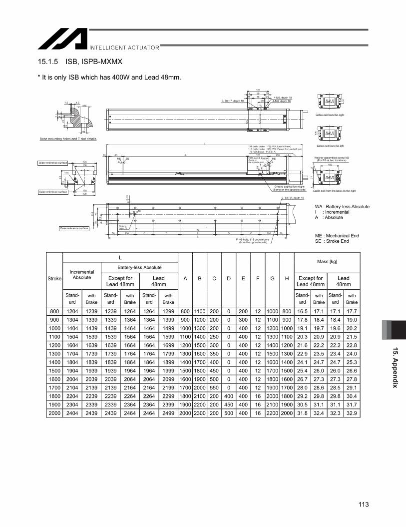
15. Appendix
113
15.1.5 ISB, ISPB-MXMX * It is only ISB which has 400W and Lead 48mm.
5
A80
5824
91
120 10012 14
L
MESEME
110120
134106
622
08
102
177
2
7021
20.0
021
607090
2515
2515
120
50G
H
011
80
510.0+
10
B200CDEDC20050
0255
07
3.43.7
1.5 4.5
622
9
16
Base mounting holes and T slot details
2- 8 H7, depth 10
Base reference surface
Home
Base reference surface
Slider reference surface
2-M3 depth 6 (Same on the opposite side)
Grease application nipple (Same on the opposite side)
2- 8 H7, depth 10
4-M6, depth 18
Oblong,depth 10
F- 9 hole, 16 counterbore(from the opposite side)
Cable exit from the back on the right
Cable exit from the right
Cable exit from the left
4-M8, depth 18
138 (with brake: 173) (WA: Lead 48 mm)113 (with brake: 138) (WA: Except for Lead 48 mm) 78 (with brake : 113) (I, A)
Washer assembled screw M3(For FG at two locations)
T slot
L
Battery-less Absolute Mass [kg]
Incremental Absolute Except for
Lead 48mm Lead
48mm Except for
Lead 48mm Lead
48mm Stroke
Stand- ard
with Brake
Stand- ard
with Brake
Stand- ard
with Brake
A B C D E F G H
Stand- ard
with Brake
Stand-ard
with Brake
800 1204 1239 1239 1264 1264 1299 800 1100 200 0 200 12 1000 800 16.5 17.1 17.1 17.7900 1304 1339 1339 1364 1364 1399 900 1200 200 0 300 12 1100 900 17.8 18.4 18.4 19.0
1000 1404 1439 1439 1464 1464 1499 1000 1300 200 0 400 12 1200 1000 19.1 19.7 19.6 20.21100 1504 1539 1539 1564 1564 1599 1100 1400 250 0 400 12 1300 1100 20.3 20.9 20.9 21.51200 1604 1639 1639 1664 1664 1699 1200 1500 300 0 400 12 1400 1200 21.6 22.2 22.2 22.81300 1704 1739 1739 1764 1764 1799 1300 1600 350 0 400 12 1500 1300 22.9 23.5 23.4 24.01400 1804 1839 1839 1864 1864 1899 1400 1700 400 0 400 12 1600 1400 24.1 24.7 24.7 25.31500 1904 1939 1939 1964 1964 1999 1500 1800 450 0 400 12 1700 1500 25.4 26.0 26.0 26.61600 2004 2039 2039 2064 2064 2099 1600 1900 500 0 400 12 1800 1600 26.7 27.3 27.3 27.81700 2104 2139 2139 2164 2164 2199 1700 2000 550 0 400 12 1900 1700 28.0 28.6 28.5 29.11800 2204 2239 2239 2264 2264 2299 1800 2100 200 400 400 16 2000 1800 29.2 29.8 29.8 30.41900 2304 2339 2339 2364 2364 2399 1900 2200 200 450 400 16 2100 1900 30.5 31.1 31.1 31.72000 2404 2439 2439 2464 2464 2499 2000 2300 200 500 400 16 2200 2000 31.8 32.4 32.3 32.9
ME : Mechanical End SE : Stroke End
WA : Battery-less Absolute I : Incremental A : Absolute
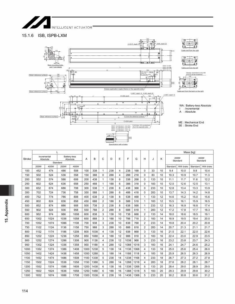
15. A
ppen
dix
114
15.1.6 ISB, ISPB-LXM
5
A
5
33
2324
26
15015 55 23
L
MESEME
134166
622
95
140150
T slot
885
2 130
150
±0.0
2
75
8
3090301512015
150
2- 8 H7, depth 10 8-M8, depth 20
150
11035150H×200 pitchJ505020
50
GF
BC×200 pitchD50
10 (from the reference surface)
120
±0.0
2
2- 8H7, depth 10 K-M8, depth 20
E- 9 hole, 16 counterbore(from the opposite side)
2- 8H7, depth 10
80+0
.015 10
90140
702510
120
4.3
622
7.3
1.5 4.5
16
98
Base mounting holes and T slot details
Slider reference surface
Base reference surface
Base reference surface Oblong,depth 10
2-M3 depth 6 (Same on the opposite side)
Home
Grease application nipple (Same on the opposite side)
Specification with a brake
Cable exit from the right
Cable exit from the left
Cable exit from the back on the right
Washer assembled screw M3(For FG at two locations)
200W: 135 (Standard + 25) (WA)400W: 157 (Standard + 25) (WA)200W: 110 (Standard + 34) (I, A)400W: 132 (Standard + 34) (I, A)
200W: 110 (WA)400W: 132 (WA)200W: 76 (I, A)400W: 98 (I, A)
L Mass [kg] Incremental
Absolute Battery-less
Absolute Standard
200W Standard
400W Standard
Stroke
200W 400W 200W 400W
A B C D E F G H J K
Standard With brake Standard With brake
100 452 474 486 508 100 338 1 238 4 238 168 0 33 10 9.4 10.0 9.8 10.4 150 502 524 536 558 150 388 0 288 4 288 218 0 83 10 10.3 10.9 10.7 11.3 200 552 574 586 608 200 438 1 138 6 338 268 0 133 10 11.1 11.7 11.6 12.2 250 602 624 636 658 250 488 1 188 6 388 318 0 183 10 12.0 12.6 12.5 13.1 300 652 674 686 708 300 538 1 238 6 438 368 0 233 10 12.8 13.4 13.3 13.9 350 702 724 736 758 350 588 1 288 6 488 418 0 283 10 13.7 14.3 14.2 14.8 400 752 774 786 808 400 638 2 138 8 538 468 1 133 12 14.6 15.2 15.0 15.6 450 802 824 836 858 450 688 2 188 8 588 518 1 183 12 15.5 16.1 15.9 16.5 500 852 874 886 908 500 738 2 238 8 638 568 1 233 12 16.3 16.9 16.8 17.4 550 902 924 936 958 550 788 2 288 8 688 618 1 283 12 17.2 17.8 17.7 18.3 600 952 974 986 1008 600 838 3 138 10 738 668 2 133 14 18.0 18.6 18.5 19.1 650 1002 1024 1036 1058 650 888 3 188 10 788 718 2 183 14 18.9 19.5 19.4 20.0 700 1052 1074 1086 1108 700 938 3 238 10 838 768 2 233 14 19.8 20.4 20.2 20.8 750 1102 1124 1136 1158 750 988 3 288 10 888 818 2 283 14 20.7 21.3 21.1 21.7 800 1152 1174 1186 1208 800 1038 4 138 12 938 868 3 133 16 21.5 22.1 22.0 22.6 850 1202 1224 1236 1258 850 1088 4 188 12 988 918 3 183 16 22.4 23.0 22.9 23.5 900 1252 1274 1286 1308 900 1138 4 238 12 1038 968 3 233 16 23.2 23.8 23.7 24.3 950 1302 1324 1336 1358 950 1188 4 288 12 1088 1018 3 183 16 24.1 24.7 24.6 25.2
1000 1352 1374 1386 1408 1000 1238 5 138 14 1138 1068 4 133 18 25.0 25.6 25.4 26.0 1050 1402 1424 1436 1458 1050 1288 5 188 14 1188 1118 4 183 18 25.9 26.5 26.3 26.9 1100 1452 1474 1486 1508 1100 1338 5 238 14 1238 1168 4 233 18 26.7 27.3 27.2 27.8 1150 1502 1524 1536 1558 1150 1388 5 288 14 1288 1218 4 283 18 27.6 28.2 28.1 28.7 1200 1552 1574 1586 1608 1200 1438 6 138 16 1338 1268 5 133 20 28.4 29.0 28.9 29.5 1250 1602 1624 1636 1658 1250 1488 6 188 16 1388 1318 5 183 20 29.3 29.9 29.8 30.2 1300 1652 1674 1686 1708 1300 1538 6 238 16 1438 1368 5 233 20 30.2 30.8 30.6 31.2
WA : Battery-less Absolute I : Incremental A : Absolute
ME : Mechanical End SE : Stroke End

15. Appendix
115
15.1.7 ISB, ISPB-LXL
5
A
5
33
2824
26
18015 55 23
L
MESEME
134166
622
95
140150
T slot
885
2 130
150
±0.0
2
90
8
4590451016010
180
2- 8H7, depth 10 8-M8, depth 20
150
11035150H×200 pitchJ505020
50
GF
BC×200 pitchD50
10 (from the reference surface)
120
±0.0
2
2- 8H7, depth 10 K-M8, depth 20
E- 9 hole, 16 counterbore(from the opposite side)
2- 8H7, depth 10
80+0.0
15 10
90140
702510
120
4.3
622
7.3
1.5 4.5
16
98
Slider reference surface
Base reference surface
Base reference surface
Base mounting holes and T slot details
Oblong, depth 10
2-M3 depth 6 (Same on the opposite side)
Home
Grease application nipple (Same on the opposite side)
Specification with a brake
Cable exit from the right
Cable exit from the left
Cable exit from the back on the right
Washer assembled screw M3(For FG at two locations)
200W: 135 (Standard + 25) (WA)400W: 157 (Standard + 25) (WA)200W: 110 (Standard + 34) (I, A)400W: 132 (Standard + 34) (I, A)
200W: 110 (WA)400W: 132 (WA)200W: 76 (I, A)400W: 98 (I, A)
L Mass [kg] Incremental
Absolute Battery-less
Absolute Standard
200W Standard
400W Standard
Stroke
200W 400W 200W 400W
A B C D E F G H J K
Standard With brake Standard With brake
120 502 524 536 558 120 388 0 288 4 288 218 0 83 10 9.8 10.4 10.2 10.8170 552 574 586 608 170 438 1 138 6 338 268 0 133 10 10.7 11.3 11.1 11.7220 602 624 636 658 220 488 1 188 6 388 318 0 183 10 11.5 12.1 12.0 12.6270 652 674 686 708 270 538 1 238 6 438 368 0 233 10 12.4 13.0 12.9 13.5320 702 724 736 758 320 588 1 288 6 488 418 0 283 10 13.2 13.8 13.7 14.3370 752 774 786 808 370 638 2 138 8 538 468 1 133 12 14.1 14.7 14.6 15.2420 802 824 836 858 420 688 2 188 8 588 518 1 183 12 15.0 15.6 15.4 16.0470 852 874 886 908 470 738 2 238 8 638 568 1 233 12 15.9 16.5 16.3 16.9520 902 924 936 958 520 788 2 288 8 688 618 1 283 12 16.7 17.3 17.2 17.8570 952 974 986 1008 570 838 3 138 10 738 668 2 133 14 17.6 18.2 18.1 18.7620 1002 1024 1036 1058 620 888 3 188 10 788 718 2 183 14 18.4 19.0 18.9 19.5670 1052 1074 1086 1108 670 938 3 238 10 838 768 2 233 14 19.3 19.9 19.8 20.4720 1102 1124 1136 1158 720 988 3 288 10 888 818 2 283 14 20.2 20.8 20.6 21.2770 1152 1174 1186 1208 770 1038 4 138 12 938 868 3 133 16 21.1 21.7 21.5 22.1820 1202 1224 1236 1258 820 1088 4 188 12 988 918 3 183 16 21.9 22.5 22.4 23.0870 1252 1274 1286 1308 870 1138 4 238 12 1038 968 3 233 16 22.8 23.4 23.3 23.9920 1302 1324 1336 1358 920 1188 4 288 12 1088 1018 3 183 16 23.6 24.2 24.1 24.7970 1352 1374 1386 1408 970 1238 5 138 14 1138 1068 4 133 18 24.5 25.1 25.0 25.6
1020 1402 1424 1436 1458 1020 1288 5 188 14 1188 1118 4 183 18 25.4 26.0 25.8 26.41070 1452 1474 1486 1508 1070 1338 5 238 14 1238 1168 4 233 18 26.3 26.9 26.7 27.31120 1502 1524 1536 1558 1120 1388 5 288 14 1288 1218 4 283 18 27.1 27.7 27.6 28.21170 1552 1574 1586 1608 1170 1438 6 138 16 1338 1268 5 133 20 28.0 28.6 28.5 29.11220 1602 1624 1636 1658 1220 1488 6 188 16 1388 1318 5 183 20 28.8 29.4 29.3 29.91270 1652 1674 1686 1708 1270 1538 6 238 16 1438 1368 5 233 20 29.7 30.3 30.2 30.8
WA: Battery-less Absolute I : Incremental A : Absolute
ME : Mechanical End SE : Stroke End

15. A
ppen
dix
116
15.1.8 ISB, ISPB-LXMX
5
A
5
79
2324
26
15015 107 23
L
MESEME
134166
622
95
140150
T slot
885
2 130
150 ±
0.02
75
8
3090301512015
150
2- 8H7 , depth 10 8-M8, depth 20
150
50F
BE- 9 hole, 16 counterbore(from the opposite side)
2- 8H7, depth 10
80+0
.015
10
140
70
G
C×200 pitchD400C×200 pitch D50
2590
4.3
622
7.3
1.5 4.5
9
16
Base mounting holes and T slot details
Slider reference surface
Base reference surface
Base reference surface Oblong,depth 10
2-M3 depth 6 (Same on the opposite side)
Home
Grease application nipple (Same on the opposite side)
Specification with a brake
Cable exit from the right
Cable exit from the left
Cable exit from the back on the right
Washer assembled screw M3(For FG at two locations)
200W: 135 (Standard + 25) (WA)400W: 157 (Standard + 25) (WA)200W: 110 (Standard + 34) (I, A)400W: 132 (Standard + 34) (I, A)
200W: 110 (WA)400W: 132 (WA)200W: 76 (I, A)400W: 98 (I, A)
L Mass [kg] Incremental
Absolute Battery-less
Absolute
Standard
200W Standard
400W Standard Stroke
200W 400W 200W 400W
A B C D E F G
Standard With brake Standard With brake
1000 1464 1486 1498 1520 1014 1350 1 225 12 1250 1050 27.3 27.9 27.7 28.3 1100 1564 1586 1598 1620 1114 1450 1 275 12 1350 1150 29.0 29.6 29.5 30.1 1200 1664 1686 1698 1720 1214 1550 1 325 12 1450 1250 30.8 31.4 31.3 31.9 1300 1764 1786 1798 1820 1314 1650 1 375 12 1550 1350 32.5 33.1 33.0 33.6 1400 1864 1886 1898 1920 1414 1750 1 425 12 1650 1450 34.3 34.9 34.8 35.4 1500 1964 1986 1998 2020 1514 1850 1 475 12 1750 1550 36.1 36.7 36.5 37.1 1600 2064 2086 2098 2120 1614 1950 1 525 12 1850 1650 37.8 38.4 38.3 38.9 1700 2164 2186 2198 2220 1714 2050 1 575 12 1950 1750 39.6 40.2 40.0 40.6 1800 2264 2286 2298 2320 1814 2150 2 425 16 2050 1850 41.3 41.9 41.8 42.4 1900 2364 2386 2398 2420 1914 2250 2 475 16 2150 1950 43.1 43.7 43.5 44.1 2000 2464 2486 2498 2520 2014 2350 2 525 16 2250 2050 44.8 45.4 45.3 45.9 2100 2564 2586 2598 2620 2114 2450 2 575 16 2350 2150 46.6 47.2 47.0 47.6 2200 2664 2686 2698 2720 2214 2550 3 425 20 2450 2250 48.3 48.9 48.8 49.4 2300 2764 2786 2798 2820 2314 2650 3 475 20 2550 2350 50.1 50.7 50.6 51.2 2400 2864 2886 2898 2920 2414 2750 3 525 20 2650 2450 51.8 52.4 52.3 52.9 2500 2964 2986 2998 3020 2514 2850 3 575 20 2750 2550 53.6 54.2 54.1 54.7
WA: Battery-less Absolute I : Incremental A : Absolute
ME : Mechanical End SE : Stroke End

15. Appendix
117
15.1.9 ISB, ISPB-LXUWX
55
79 A
1824
26
2-M3 depth 6 (Same on the opposite side)
15 107 23250
L
MESEME
134166
622
95
140150
T slot
885
2 130
150 ±
0.02
40
8
10601080
2 x 2- 8H7, depth 102 x 4-M87, depth 20
150
40106010
80 90250
150
150 ±
0.02
8
50F
BE- 9 hole, 16 counterbore(from the opposite side)
2- 8H7, depth 10
80+0
.015
10
140
70
G
C×200 pitchD400C×200 pitch D50
2590
4.3
622
7.3
1.5 4.5
f9
f16
Slider reference surface
Base reference surface
Base reference surface
Base mounting holes and T slot details
Oblong, depth 10
Home
Grease application nipple (Same on the opposite side)
Specification with a brake
Cable exit from the right
Cable exit from the left
Cable exit from the back on the right
Washer assembled screw M3(For FG at two locations)
200W: 135 (Standard + 25) (WA)400W: 157 (Standard + 25) (WA)200W: 110 (Standard + 34) (I, A)400W: 132 (Standard + 34) (I, A)
200W: 110 (WA)400W: 132 (WA)200W: 76 (I, A)400W: 98 (I, A)
L Mass [kg] Incremental
Absolute Battery-less
Absolute Standard
200W Standard
400W Standard
Stroke
200W 400W 200W 400W
A B C D E F G
Standard With brake Standard With brake
1000 1564 1586 1598 1620 1014 1450 1 275 12 1350 1150 30.4 31.0 30.8 31.4 1100 1664 1686 1698 1720 1114 1550 1 325 12 1450 1250 32.1 32.7 32.6 33.2 1200 1764 1786 1798 1820 1214 1650 1 375 12 1550 1350 33.9 34.5 34.3 34.9 1300 1864 1886 1898 1920 1314 1750 1 425 12 1650 1450 35.6 36.2 36.1 36.7 1400 1964 1986 1998 2020 1414 1850 1 475 12 1750 1550 37.4 38.0 37.8 38.4 1500 2064 2086 2098 2120 1514 1950 1 525 12 1850 1650 39.1 39.7 39.6 40.2 1600 2164 2186 2198 2220 1614 2050 1 575 12 1950 1750 40.9 41.5 41.4 42.0 1700 2264 2286 2298 2320 1714 2150 2 425 16 2050 1850 42.6 43.2 43.1 43.7 1800 2364 2386 2398 2420 1814 2250 2 475 16 2150 1950 44.4 45.0 44.9 45.5 1900 2464 2486 2498 2520 1914 2350 2 525 16 2250 2050 46.1 46.7 46.6 47.2 2000 2564 2586 2598 2620 2014 2450 2 575 16 2350 2150 47.9 48.5 48.4 49.0 2100 2664 2686 2698 2720 2114 2550 3 425 20 2450 2250 49.7 50.3 50.1 50.7 2200 2764 2786 2798 2820 2214 2650 3 475 20 2550 2350 51.4 52.0 51.9 60.5 2300 2864 2886 2898 2920 2314 2750 3 525 20 2650 2450 53.2 53.8 53.6 54.2 2400 2964 2986 2998 3020 2414 2850 3 575 20 2750 2550 54.9 55.5 55.4 56.0 2500 3064 3086 3098 3120 2514 2950 3 625 20 2850 2650 56.7 57.3 57.1 57.7
WA: Battery-less Absolute I : Incremental A : Absolute
ME : Mechanical End SE : Stroke End

15. A
ppen
dix
118
15.1.10 SSPA-SXM
L Mass [kg] Stroke Standard With brake
M N P R m n r t Standard With brake
100 398 433 240 140 140 45 1 0 4 2 6.8 7.4 150 448 483 290 190 40 70 1 1 6 2 7.4 8.0 200 498 533 340 240 90 20 2 1 6 3 8.1 8.7 250 548 583 390 290 140 45 2 1 6 3 8.7 9.3 300 598 633 440 340 40 70 2 2 8 3 9.3 9.9 350 648 683 490 390 90 20 3 2 8 4 10.0 10.6 400 698 733 540 440 140 45 3 2 8 4 10.6 11.2 450 748 783 590 490 40 70 3 3 10 4 11.2 11.8 500 798 833 640 540 90 20 4 3 10 5 11.9 12.5 550 848 883 690 590 140 45 4 3 10 5 12.5 13.1 600 898 933 740 640 40 70 4 4 12 5 13.1 13.7 650 948 983 790 690 90 20 5 4 12 6 13.8 14.4 700 998 1033 840 740 140 45 5 4 12 6 14.4 15.0 750 1048 1083 890 790 40 70 5 5 14 6 15.0 15.6 800 1098 1133 940 840 90 20 6 5 14 7 15.6 16.2 850 1148 1183 990 890 140 45 6 5 14 7 16.3 16.9 900 1198 1233 1040 940 40 70 6 6 16 7 16.9 17.5 950 1248 1283 1090 990 90 20 7 6 16 8 17.5 18.1
1000 1298 1333 1140 1040 140 45 7 6 16 8 18.2 18.8 1050 1348 1383 1190 1090 40 70 7 7 18 8 18.8 19.4 1100 1398 1433 1240 1140 90 20 8 7 18 9 19.4 20.0
Slider reference surface
2-φ6H7 depth 8 9017.5 17.555 ±0.02
6.5
±0.0
2
6.5
8598
6-M6 depth 9 7.5 7.537.5 37.570
Slider reference surface
100981 1
100924 4
7010
6
2.5
Base reference surface
12 25 Stroke
L
90 25 12 134 (With brake : 169)5
33 4.52-M3 depth 3(Same on the opposite side)
Home Mechanical end
16
25.5 (M3 tap)
Cable exit from the right
Cable exit from the left
Cable exit from the back on the right
Cable exit from the back on the left
Washerasssembled screen M3(For FG at two locations)
2.5
2.5
65
t-M3 depth 3(Same on the opposite side)
R150 pitch × mR
Mechanical end Stroke end
Grease application nipple(Same on the opposite sidefor both guide and ball screw)
150 pitch × nM
P50 5020 r-M6 depth 9
r-φ7 hole6 4.5
5
φ12 φ7
M6
Cross section drawing X-X(Details of base mounting hole)
6 ±0.02(from the reference surface)
9
30
6+0.012 0
Oblong, depth 8N
6 ±0.02(from the reference surface)
φ6H7 depth 870
X
X
Base reference surface
50 80 92
216

15. Appendix
119
15.1.11 SSPA-MXM
Slider reference surface
2-φ8H7 depth 1070 ±0.02
12025 25
9 ±0
.02
911
012
8
10 1050 50
896-M8 depth 12
Cable exit from the right
Cable exit from the left
Cable exit from the back on the right
Washerasssembled screen M3(For FG at two locations)
2.5
752.
5
Cable exit from the back on the left
Slider reference surface
Base reference surface
1301281 1
120130
5 5
808.
510
2.5
φ15
φ9M
8
8 5.5
Cross section drawing X-X(Details of base mounting hole)
10 ±0.02(from the reference surface)
Oblong, depth 1029
8+0.015 0
12N 89
10 ±0.02(from the reference surface)
φ8H7 depth 10 Base reference surface
X
X 70 100
120
2510
r-M8 depth 12r-φ9 hole
6029
200 pitch × nM
P60
34.5 (M3 tap)
t-M3 depth 4(Same on the opposite side)
R150 pitch × mGrease application nipple(Same on the opposite sidefor both guide and ball screw)
R
Mechanical end Stroke end
15 295
Stroke
L
120 29 15 150 (With brake : 185)5
33 4.5
17
2-M3 depth 6(Same on the opposite side)
Home Mechanical end
L Mass [kg] Stroke Standard With brake
M N P R m n r t Standard With brake
100 458 493 278 160 158 64 1 0 4 2 12.4 13.0 150 508 543 328 210 208 14 2 0 4 3 13.5 14.1 200 558 593 378 260 58 39 2 1 6 3 14.6 15.2 250 608 643 428 310 108 64 2 1 6 3 15.7 16.3 300 658 693 478 360 158 14 3 1 6 4 16.7 17.3 350 708 743 528 410 208 39 3 1 6 4 17.8 18.4 400 758 793 578 460 58 64 3 2 8 4 18.9 19.5 450 808 843 628 510 108 14 4 2 8 5 20.0 20.6 500 858 893 678 560 158 39 4 2 8 5 21.1 21.7 550 908 943 728 610 208 64 4 2 8 5 22.2 22.8 600 958 993 778 660 58 14 5 3 10 6 23.2 23.8 650 1008 1043 828 710 108 39 5 3 10 6 24.3 24.9 700 1058 1093 878 760 158 64 5 3 10 6 25.4 26.0 750 1108 1143 928 810 208 14 6 3 10 7 26.5 27.1 800 1158 1193 978 860 58 39 6 4 12 7 27.6 28.2 850 1208 1243 1028 910 108 64 6 4 12 7 28.7 29.3 900 1258 1293 1078 960 158 14 7 4 12 8 29.7 30.3 950 1308 1343 1128 1010 208 39 7 4 12 8 30.8 31.4
1000 1358 1393 1178 1060 58 64 7 5 14 8 31.9 32.5 1050 1408 1443 1228 1110 108 14 8 5 14 9 33.0 33.6 1100 1458 1493 1278 1160 158 39 8 5 14 9 34.1 34.7 1150 1508 1543 1328 1210 208 64 8 5 14 9 35.2 35.8 1200 1558 1593 1378 1260 58 14 9 6 16 10 36.2 36.8 1250 1608 1643 1428 1310 108 39 9 6 16 10 37.3 37.9 1300 1658 1693 1478 1360 158 64 9 6 16 10 38.4 39.0

15. A
ppen
dix
120
X
X
101035
45
150
45 19. 519. 5
02
3515 31
RR
43
85.585.5
5.2
09
153
01
140
155
9
1551 1
7.5 7.5
585.2
5.2
110
110 N
041
75 P 75M
110
09021
5201 10 ±0.02 10 ±0.028 H7 0+0.015
φ8H70 depth 12+0.015
35
12
100±0.02
65 65
153
10 10
25 252-φ8H70 depth 12
+0.015
9 ±0
.02
913
5
150
110
21Ø
9Ø
51Ø
21010
8M
6-M8, depth 16
Base reference surface
Base reference surface
Slider reference surface
t-M3 depth 4(Same on the opposite side)
Grease application nipple(Same on the opposite side)for both guide and ball screw Cable exit from the back on the right
Cable exit from the right
Cable exit from the left
Washerasssembled screen M4(For FG at two locations)
Slider reference surface
36 (M3 tap)
(300: Up to cable joint connector)
Standard is 174, specificates with brake is 211L: Standard is ST+440, specificates with brake is ST+477
r-M8 depth 16
(from the reference surface)
Optional cable exit directionselection possible
Stroke
Mechanical endHome
Stroke endMechanical end
2-M3, depth 6(Same on the opposite side)2-M4, depth 8(Same on the opposite side)
r- , 9 hole
200 pitch x n
(from the reference surface)
Oblong, depth 12Cross section drawing X-X
Scale 1:1(Details of base mounting hole)
200 pitch x m
15.1.12 SSPA-LXM
L Mass [kg] Stroke Standard With brake
M N P R m n r t Standard With brake
100 540 577 320 100 170 60 1 0 4 2 21.0 22.0 150 590 627 370 150 220 85 1 0 4 2 23.0 24.0 200 640 677 420 200 70 10 2 1 6 3 25.0 26.0 250 690 727 470 250 120 35 2 1 6 3 26.5 27.5 300 740 777 520 300 170 60 2 1 6 3 28.0 29.0 350 790 827 570 350 220 85 2 1 6 3 29.5 30.5 400 840 877 620 400 70 10 3 2 8 4 31.0 32.0 450 890 927 670 450 120 35 3 2 8 4 33.0 34.0 500 940 927 720 500 170 60 3 2 8 4 35.0 36.0 550 990 1027 770 550 220 85 3 2 8 4 36.5 37.5 600 1040 1077 820 600 70 10 4 3 10 5 38.0 39.0 650 1090 1127 870 650 120 35 4 3 10 5 39.5 40.5 700 1140 1177 920 700 170 60 4 3 10 5 41.0 42.0 750 1190 1227 970 750 220 85 4 3 10 5 43.0 44.0 800 1240 1277 1020 800 70 10 5 4 12 6 45.0 46.0 850 1290 1327 1070 850 120 35 5 4 12 6 46.5 47.5 900 1340 1377 1120 900 170 60 5 4 12 6 48.0 49.0 950 1390 1427 1170 950 220 85 5 4 12 6 49.5 50.5
1000 1440 1477 1220 1000 70 10 6 5 14 7 51.0 52.0 1050 1490 1527 1270 1050 120 35 6 5 14 7 52.5 53.5 1100 1540 1577 1320 1100 170 60 6 5 14 7 54.0 55.0 1150 1590 1627 1370 1150 220 85 6 5 14 7 56.0 57.0 1200 1640 1677 1420 1200 70 10 7 6 16 8 58.0 59.0 1250 1690 1727 1470 1250 120 35 7 6 16 8 59.5 60.5 1300 1740 1777 1520 1300 170 60 7 6 16 8 61.0 62.0 1350 1790 1827 1570 1350 220 85 7 6 16 8 62.5 63.5 1400 1840 1877 1620 1400 70 10 8 7 18 9 64.0 65.0 1450 1890 1927 1670 1452 120 35 8 7 18 9 66.0 67.0 1500 1940 1977 1720 1500 170 60 8 7 18 9 68.0 69.0

16. Warranty
121
16. Warranty 16.1 Warranty Period One of the following periods, whichever is shorter: 18 months after shipment from our company 12 months after delivery to the specified location 2,500 hours of operation
16.2 Scope of Warranty Our products are covered by warranty when all of the following conditions are met. Faulty products covered by warranty will be replaced or repaired free of charge: (1) The breakdown or problem in question pertains to our product as delivered by us or our authorized dealer. (2) The breakdown or problem in question occurred during the warranty period. (3) The breakdown or problem in question occurred while the product was in use for an appropriate purpose
under the conditions and environment of use specified in the operation manual and catalog. (4) The breakdown or problem in question was caused by a specification defect or problem, or by the poor
quality of our product. Note that breakdowns due to any of the following reasons are excluded from the scope of warranty:
[1] Anything other than our product [2] Modification or repair performed by a party other than us (unless we have approved such modification or
repair) [3] Anything that could not be easily predicted with the level of science and technology available at the time
of shipment from our company [4] A natural disaster, man-made disaster, incident or accident for which we are not liable [5] Natural fading of paint or other symptoms of aging [6] Wear, depletion or other expected result of use [7] Operation noise, vibration or other subjective sensation not affecting function or maintenance
Note that the warranty only covers our product as delivered and that any secondary loss arising from a breakdown of our product is excluded from the scope of warranty. 16.3 Honoring the Warranty As a rule, the product must be brought to us for repair under warranty.

16. W
arra
nty
122
16.4 Limited Liability (1) We shall assume no liability for any special damage, consequential loss or passive loss such as a loss of
expected profit arising from or in connection with our product. (2) We shall not be liable for any program or control method created by the customer to operate our product or
for the result of such program or control method. 16.5 Conditions of Conformance with Applicable Standards/Regulations, Etc., and
Applications (1) If our product is combined with another product or any system, device, etc., used by the customer, the
customer must first check the applicable standards, regulations and/or rules. The customer is also responsible for confirming that such combination with our product conforms to the applicable standards, etc. In such a case we will not be liable for the conformance of our product with the applicable standards, etc.
(2) Our product is for general industrial use. It is not intended or designed for the applications specified below, which require a high level of safety. Accordingly, as a rule our product cannot be used in these applications. Contact us if you must use our product for any of these applications:
[1] Medical equipment pertaining to maintenance or management of human life or health [2] A mechanism or mechanical equipment intended to move or transport people (such as a vehicle,
railway facility or aviation facility) [3] Important safety parts of mechanical equipment (such as safety devices) [4] Equipment used to handle cultural assets, art or other irreplaceable items
(3) Contact us at the earliest opportunity if our product is to be used in any condition or environment that differs from what is specified in the catalog or operation manual.
16.6 Other Items Excluded from Warranty The price of the product delivered to you does not include expenses associated with programming, the dispatch of engineers, etc. Accordingly, a separate fee will be charged in the following cases even during the warranty period:
[1] Guidance for installation/adjustment and witnessing of test operation [2] Maintenance and inspection [3] Technical guidance and education on operating/wiring methods, etc. [4] Technical guidance and education on programming and other items related to programs

Change H
istory
123
Change History
Revision Date Description of Revision
July 2011
November 2011
March 2012
March 2012
November 2012
January 2013
March 2013
First edition Second edition
Contents changed in Safety Guide Caution notes added for when working with two or more persons SSPA-SXM, MXM added
Third edition
Pg. 31, 37 ISP and ISPB Note changed to 1.8 times more of the nominal diameter for the length of thread engagement Pg. 59 “This is an option limited to the high-precision specifications (ISPB/SSPA).” deletedNote added to tell the straightness is 0.025mm for all with stroke 500mm or less unless the model is the high-precision specifications one.
Fourth edition
Pg. 1 to 7 Contents added and changed in Safety Guide Pg. 8 Note “Make sure to attach the actuator properly by following this operation manual.”added in Caution in Handling Pg. 69 Warning notes added such as in case the grease got into your eye, immediately go to see the doctor for an appropriate care. Pg. 90 to 101 Weight added to appearance drawing
Fifrth edition
Pg. 45 Line of LF = 100% added in graph.
Sixrth edition Pg. 29 Note changed to available to mount less than 1300mm for stroke for ceiling mount of ISB, SIPB-MXMX/LXMX/LXUWX Pg. 44 Correction made to some area in items to be prohibited in handling of cables Pg. 45 Calculation formula added for when commanded acceleration speed is higher than rated acceleration speed
Seventh edition
Pg. 35 The unit of flatness changed
0.05 mm → 0.05 mm/m 0.02 mm → 0.02 mm/m

Cha
nge
His
tory
124
Revision Date Description of Revision
June 2013
December 2013
May 2014
November 2014
December 2014
April 2015
July 2015
October 2015
April 2016
Eighth edition Pg. 67 Grease before factory at intermediate support changed to Daphne Eponex Grease No. 2
Ninth edition
Pg. 69 Information added for when grease supply from grease nipple is not possible Pg. 87 Note corrected In table N m → N cm
Tenth edition Change partly made to “14. Motor Replacement Procedures” in accord with change of replacement motor
10C edition Pg. 65 Joint deleted from the table
Eleventh edition Pg. 64 Change made to grease supply period Pg. 68 to 69 Recommended grease gun at grease supply added
Twelfth edition Pg. 11, 12 Touch panel teahing TB-01 added Pg. 12, 13, 49, 52, 63, 98 Dedicated controller added Pg. 13, 62, 65, 66 Option EU (Metal connector type) added Pg. 21, 23 Dynamic allowable moment value changed Pg. 24 Change made about life
12B edition Pg. 63 Wiring table of CB-X-MA□□□ Correction made of mechanical side
12C edition Pg. 67 Period of grease supply (reference) added for actuators with guide equipped with ball retainer Pg. 39, 102, 105 Four tapped holes added on top surface of slider for MXL and LXL
Thirteenth edition Contents added for Battery-less Absolute

Change H
istory
125
Revision Date Description of Revision
April 2016
September 2016
September 2016
November 2016
February 2018
13B edition Pg. 73 Grease gun and nozzle changed
13C edition
Pg. 39 LXUWX slider drawings added
Fourteen edition
Contents added for Lead 36mm of ISB-SXM and SXL and Lead 48mm of ISB-MXM, MXL and MXMX
14B edition Pg. 16, 17 “Acceleration/deceleration” and “creep phenomenon or slipped coupling” deleted Pg. 18 to 23 Caution note added for interpolated operation of two or more orthogonal axes
14C edition Pg. 76 Correction made to model of grease Multemp ET-R No.2 → Multemp ET-R


Manual No.: ME3708-14C (February 2018)
The information contained in this document is subject to change without notice for purposes of product improvement.Copyright © 2018. Feb. IAI Corporation. All rights reserved.
18.02.000
Head Office: 577-1 Obane Shimizu-KU Shizuoka City Shizuoka 424-0103, JapanTEL +81-54-364-5105 FAX +81-54-364-2589
website: www.iai-robot.co.jp/
Ober der Röth 4, D-65824 Schwalbach am Taunus, GermanyTEL 06196-88950 FAX 06196-889524
SHANGHAI JIAHUA BUSINESS CENTER A8-303, 808, Hongqiao Rd. Shanghai 200030, ChinaTEL 021-6448-4753 FAX 021-6448-3992
website: www.iai-robot.com
825 PhairojKijja Tower 12th Floor, Bangna-Trad RD., Bangna, Bangna, Bangkok 10260, ThailandTEL +66-2-361-4458 FAX +66-2-361-4456
Technical Support available in USA, Europe and China
Head Office: 2690 W. 237th Street, Torrance, CA 90505TEL (310) 891-6015 FAX (310) 891-0815
Chicago Office: 110 East State Parkway, Schaumburg, IL 60173TEL (847) 908-1400 FAX (847) 908-1399
TEL (678) 354-9470 FAX (678) 354-9471website: www.intelligentactuator.com
Atlanta Office: 1220 Kennestone Circle, Suite 108, Marietta, GA 30066