Sprinkler Systems Central Sprinkler Corporation: Complaint Part 6

Disclosure to Promote the Right To Information
Whereas the Parliament of India has set out to provide a practical regime of right to information for citizens to secure access to information under the control of public authorities, in order to promote transparency and accountability in the working of every public authority, and whereas the attached publication of the Bureau of Indian Standards is of particular interest to the public, particularly disadvantaged communities and those engaged in the pursuit of education and knowledge, the attached public safety standard is made available to promote the timely dissemination of this information in an accurate manner to the public.
इंटरनेट मानक
“!ान $ एक न' भारत का +नम-ण”Satyanarayan Gangaram Pitroda
“Invent a New India Using Knowledge”
“प0रा1 को छोड न' 5 तरफ”Jawaharlal Nehru
“Step Out From the Old to the New”
“जान1 का अ+धकार, जी1 का अ+धकार”Mazdoor Kisan Shakti Sangathan
“The Right to Information, The Right to Live”
“!ान एक ऐसा खजाना > जो कभी च0राया नहB जा सकता है”Bhartṛhari—Nītiśatakam
“Knowledge is such a treasure which cannot be stolen”
“Invent a New India Using Knowledge”
है”ह”ह
IS 9972 (2002): Specification for Automatic Sprinkler Headsfor Fire Protection Service [CED 22: Fire Fighting]

3Tfmm’wTmT@(
r,A—
?,
1—
IS 9972:2002‘tj.:,
Wmwm5 “ii$,
mR-dfw%aT*?/3m “
W5aq@twr),,;.,.7
:,
~ ‘j
.
Indian Standard
SPECIFICATION FOR AUTOMATIC SPRINKLERHEADS FOR FIRE PROTECTION SERVICE
( First Revision) 4
ICS 13.220.10$
,,,..
0 BIS 2002
BUREAU OF IN DIAN STANDARDSMANAK BHAVAN, 9 BAHADUR SHAH ZAFAR MARC
NEW DELHI 110002
Price Group 10September 2002

Fire Fighting Sectional Committee, CED 22
FOREWORD
This Indian Standard was adopted by the Bureau of Indian Standards, after the draft finalized by the FireFighting Sectional Committee had been approved by the Civil Engineering Division Counci 1.
A sprinkler system consists of a water supply and one or more sprinkler installations; each installation consistingof a set of installation control valve and a pipe array fitted with sprinkler heads. The sprinkler heads are fittedat specified locations at the roof or ceiling, and where necessary between racks, below shelves, and in ovens orstoves.
The sprinklers operate at pre-determined temperatures to discharge water over the affected part of the areabelow, the flow of water through the installation control valve initiating a fire alarm. The operating temperatureis generally selected to suit ambient temperature conditions. Only the sprinklers in the vicinity of the fire, thatis, those which become sufficiently heated, operate.
A sprinkler has two functions to perform. It must first detect a fire, and must then provide an adequate distributionof water to control or extinguish it. Each function is performed separately and one is independent of the otherexcept insofar as early detection makes extinction easier because the fire has not grown large.
A sprinkler head is, in essence, a thermally operated valve which when it opens acts as a distributor of waterover a specified area. It consists of a body which screws into a pressurized pipe, and which contains a dischargeorifice. The orifice is normally sealed by a valve assembly which is held in place by a thermally sensitive fusibleelement or glass bulb. The latter will separate or burst when its operating temperature is reached. l%e otherend of the fusible element or glass bulb is supported by the yoke arms, which also serve to support the deflectorplate. On operation, the element or the bulb falls away and allows the valve to open under the pressure of water,which is ejected from the orifice and strikes the deflector plate thus distributing the water over a pre-determinedarea beneath the sprinkler. This standard has been formulated so as to cover the requirements of automaticsprinkler heads of both fusible element and glass bulb types.
This standard was first published in 1981 and since then there has been a revolution in the industry worldwidein respect of fire protection particularly in sprinkler installation. Several new types of sprinklers have beendeveloped and testing procedures for the sprinklers have been drastically changed keeping in view of the varietyof fire protection requirements. Hence this standard is being revised in tune with the international trends.
In the formulation of this standard due weightage has been given to international coordination among thestandards and practices prevailing in different countries in addition to relating it to the practices in the field ofthis country. Considerable assistance has been provided by the Tariff Advisory Committee.
The composition of the Committee responsible for formulation of this standard is given in Annex B.
For the purpose of deciding whether a particular requirement of this standard is complied with, the final value,observed or calculated, expressing the result of a test, shall be rounded off in accordance with IS 2:1960 ‘Rulesfor rounding off numerical values (revised)’. The number of significant places retained in the rounded off valueshould be the same as that of the specified value in this standard.
.
-,, .

_&
IS 9972:2002
Indian Standard
SPECIFICATION FOR AUTOMATIC SPRINKLERHEADS FOR FIRE PROTECTION SERVICE
( First Revision)
1 SCOPE
This standard covers the mechanical properties andperformance requirements of automatic sprinklerheads for installation in fire protection service.
2 REFERENCES
The Indian Standards listed below contain provisionswhich through reference in this text, constituteprovisions of this standard. At the time of publication,the editions indicated were valid. All standards aresubject to revision, and parties to agreements based onthis standard are encouraged to investigate thepossibility of applying the most recent editions of thestandards which are as follows:
[S No. Title
1239 (Part 1) : Mild steel tubes, tubulars and other1990 wrought steel fittings : Part 1 Mild
steel tubes (fifth revision)
2643 Dimensions for pipe threads forfastening purposes:
(Part 1): 1975 Basic profile and dimensions (@frevision)
(Part 2): 1975 Tolerances @rst revision)
(Part 3): 1975 Limits of sizes (first revision)
3 TERMINOLOGY
For the purpose of this standard, the followingdefinitions shall apply.
3.1 Cut off Sprinkler
A sprinkler protecting a door and/or windowbetween two areas of which only one is protected bysprinklers.
3.2 Detector Sprinkler
A sealed sprinkler mounted on a pressurized pipelineused to control a deluge valve. Operation of thissprinkler causes loss of air pressure and water pressurewhich opens the deluge valve.
33 Discharge Co-efficient
The co-efficient of discharge of a sprinkler (K) is givenby the formula given below:
K. QP-;
whereK = the co-efficient of discharges of a
sprinkler,
Q = flOW of water through the orifice ofsprinkler in I/rein, and
P = pressure of water in kg/cm2.
3.4 Heat Responsive Element
That portion of the sprinkler assembly that breaks,melts or otherwise functions to initiate the automaticoperation of the sprinkler when exposed to sufficientheat.
3.5 Lodgement
Lodgements occur when a sprinkler operates anddischarges water, but operating parts intended to fallaway do not do so, but lodge in the sprinkler yoke ordeflector, thus impairing water distribution.
3.6 (lperating Temperature
The temperature at which the heat responsive elementof a sprinkler operates when subjected to a 0.5° C /reintemperature rise while immersed in a liquid bath.
3.7 OrifkeThe opening that controls the amount of waterdischarged from a sprinkler at a given pressure.
3.S Rosette
A plate covering the gap between the shank or body ofa sprinkler projecting through a suspended ceiling andthe ceiling.
3.9 Service Load
Service load shall be considered as the averageassembly load or the average load withstood by theframe and the heat responsive element under aninstallation pressure of 10 bar, whichever is greater.The average is normally ascertained from tests on4 sprinklers.
3.10 Sprayer
A sprinkler that gives a downward conical patterndischarge.
“’
5
,,.
1

IS 9972:2002
3.11 Sprinkler
A temperature sensitive sealing device which isintended to open automatically by operation of aheat-responsive element that maintains the dischargeorifice closed by means, such as the exertion ofpressure on a cap (button or disc). A sprinkler isinstalled on a pressurized piping so that a spray ofwater discharge ofa specified pattern is achieved forthesuppression orcontrol of afire.
3.12 Yoke
The part of a sprinkler that retains the heat responsiveelement in load bearing contact with the sprinkler headvalve.
4 TYPES OF SPRINKLERS
Sprinklers of the following types are covered underthis standard.
4.1 Sprinklers According to Release Mechanism
4.L1 Fusible Element Sprinklers
A fusible element sprinkler is opened under theinfluence of heat by melting of a component.
4.L2 Glass Bulb Sprinklers
A glass bulb sprinkler is opened under the influenceof heat by the bursting of the glass bulb throughpressure resulting from expansion of the fluid enclosedtherein.
4.2 Sprinklers According to Type of Discharge
4.2.1 Conventional Sprinklers
The conventional sprinkler has a spherical waterdistribution directed towards the ground and theceiling over a definite protection area. A conventionalsprinkler shall discharge from 40 to 60 percent of thetotal water flow initially in a downward direction.
4.2.2 Spray Sprinklers
The spray sprinkler has a parabolaidal waterdistribution directed towards the ground over adefinite protection area. A spray sprinkler shalldischarge from 80 to 100 percent of the total waterflow in a downward direction.
4.2.3 Sidewall Sprinklers
The sidewall sprinkler has a one-sided (halfparabolaid) water distribution directed towards theadjacent wal I and the ground over a defined protectionarea.
4.3 Sprinklers According to Mounting Pattern
4.3.1 Pendent Sprinkler
A sprinkler intended to be installed so that its deflectoris located below the orifice and the water flowsdownward through the orifice.
4,3.2 Upright Sprinkler
A sprinkler intended to be installed so that its deflectoris located above the orifice and the water flows upwardthrough the orifice.
4.3.3 Hori.zonta[ Sprinklers (Sidewall Only)
Horizontal sprinklers are designed to give thespecified distribution when the jet of water is directedhorizontally against the deflector. This applies tosidewall sprinklers only.
4.3.4 Ceiling Sprinklers
Ceiling sprinklers are in which part of the body of thesprinkler (other than shank) may be mounted abovethe lower plane of the ceiling.
4.4 Special Sprinklers
4.4.1 Dry Upright Sprinklers
Dry upright sprinklers are installed in an uprightposition on special rise pipes. These pipes are kept freefrom water.
4.4.2 Dry Pendent Sprinklers
Dry pendent sprinklers are installed in a pendentposition on special drop pipes. These pipes are keptfree from water.
4.4.3 Flush Sprinklers
Flush sprinklers are installed in a pendent positionclose to the ceiling, such that part of the body may beabove the ceiling line, and the heat responsive elementis completely below the ceiling line.
4.4.4 Recessed Sprinklers
Recessed sprinklers are installed in a pendent positionpafily or wholly above the ceiling line. The sprinkleris fitted into a recess cup, the rim of which is flush withthe ceiling.
4.4.5 Concealed Sprinklers
Concealed sprinklers are- installed in a pendentposition above the ceiling line. The concealedsprinkler incorporates a recessing cup and ceiling platewhich enclose the sprinkler, such that the ceiling plateis flush with the ceiling and conceals the sprinkler.
4.4.6 Intermediate Sprinklers
A sprinkler instrdled below, and in addition to roofsprinklers with a specific purpose.
4.4.7 Detector Sprinkler
A sealed sprinkler mounted on a pressurized pipelineused to control a deluge valve. Operation of thissprinkler causes loss of air pressure and water pressurewhich opens the deluge valve.
2
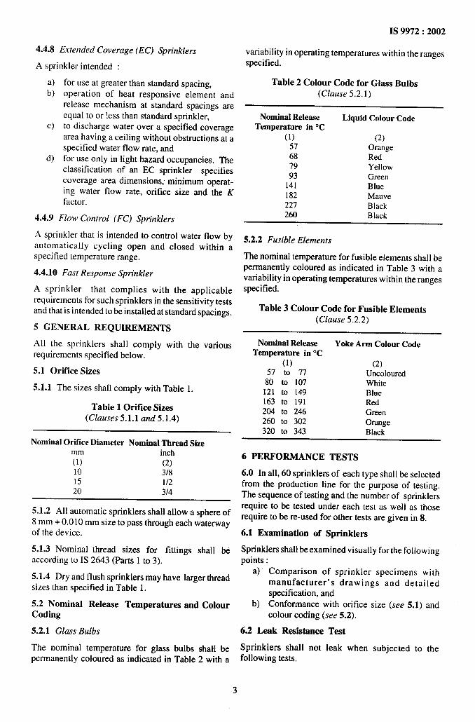
4.4.8 Extended Coverage (EC) Sprinklers
A sprinkler intended :
a)b)
c)
d)
for use at greater than standard spacing,operation of heat responsive element andrelease mechanism at standard spacings areequal to or !ess than standard sprinkler,to discharge water over a specified coveragearea having a ceiling without obstructions at aspecified water flow rate, andfor use only in light hazard occupancies. The.classification of an EC sprinkler specifiescoverage area dimensions; minimum operat-ing water flow rate, orifice size and the Kfactor.
4.4,9 Flow Control (FC) Sprinklers
A sprinkler that is intended to control water flow byautomatically cycling open and closed within aspecified temperature range.
4.4.10 Fast Response Sprinkler
A sprinkler that complies with the applicablerequirements for such sprinklers in the sensitivity testsand that is intended to be installed at standard spacings.
5 GENERAL REQUIREMENTS
All the sprinklers shall comply with the variousrequirements specified below.
5.1 Orifke Sizes
5.1.1 The sizes shall comply with Table 1.
Table 10rifice Sizes(Clauses 5.1.1 and 5.1.4)
Nominal Orifice Diameter Nominal Thread Sizemm inch(1) (2)10 3/815 1/220 3/4
5.1.2 All automatic sprinklers shall allow a sphere of8 mm + 0.010 mm size to pass through each waterwayof the device.
5.1.3 Nominal thread sizes for fittings shall beaccording to IS 2643 (Parts 1 to 3).
5.1.4 Dry and flush sprinklers may have larger threadsizes than specified in Table 1.
5.2 Nominal Release Temperatures and ColourCoding
5.2.1 Glass Bulbs
The nominal temperature for glass bulbs shall bepermanently coloured as indicated in Table 2 with a
IS 9972:2002
variability in operating temperatures within the ranges
specified.
Table 2 Colour Code for Glass Bulbs(Cfause 5.2.1)
Nominal Release Liquid Colour CodeTemperature in “C
(1) (2)57 Orange68 Red79 Yellow93 Green
141 Blue182 Mauve227 Black260 Black
5.2.2 Fusible Elements
The nominal temperature for fusible elements shall bepermanently coloured as indicated in Table 3 with avariability in operating temperatures within the rangesspecified.
Table 3 Colour Code for Fusible Elements(Clause 5.2,2)
Nominal Release Yoke Arm Colour CodeTemperature in ‘C
(1) (2)57 to 77 Uncolored
80 to 107 White121 to 149 Blue163 to 191 Red204 to 246 Green260 to 302 Orange320 to 343 Black
6 PERFORMANCE TESTS
6.0 In all, 60 sprinklers of each type shall be selectedfrom the production line for the purpose of testing.The sequence of testing and the number of sprinklersrequire to be tested under each test as well as thoserequire to be re-used for other tests are given in 8.
6.1 Examination of Sprinklers
Sprinklers shall be examined visually for the followingpoints:
a) Comparison of sprinkler specimens withmanufacturer’s drawings and detailedspecification, and
b) Conformance with orifice size (see 5.1) andcolour coding (see 5.2).
6.2 Leak Resistance Test
Sprinklers shall not leak when subjected to thefollowing tests.
3

IS 9972:2002
6.2.1 Leakage Test
Sprinklers shall be subjected to a water pressure of30 bars * 1 bar. The pressure shall be raised fromO bar to 30 bar at an average rate of S 1 bar/s. Thepressure of 30 bar shall then be maintained fora periodof 3 min + 5 s and then allowed to fall to O bar in notless than 5 s. After releasing the pressure, it shall bethen raised to 0.5 bar f 0.1 bar in not more than 5 s.This pressure shall be maintained for 15+5 s.
The pressure shall then be raised to 10 bar+ 0.5 bar atan average rate of increase of S 1 bar/s. The 10 barpressure shall be maintained for 15 + 5 s.
6.2.2 30-Day Leakage Test
Sprinklers when tested as per the following proceduresshall
a) experience no leakage when subjected to ahydrostatic pressure of 20 bars for 30 days.Five samples shall be tested and the same shallbe checked every week for evidence ofleakage;
b) not leak when subjected to a pressure of 35 barsfor one minute following the 30 days. Thepressure shall ~ increased at a rate not exceed-ing 20 bars per minute. Similarly after the test,the pressure shall be brought down to O bar ata rate not exceeding 20 bars /rein; and
c) show no distortion or other mechanicaldamage following the leakage testing, asdetermined by visual examination.
6.3 Functional Test
All operating parts of the sprinklers shall release withsharp and positive action and these shall be thrownclear of the sprinkler frames and the deflectors so asnot to impair the water distribution pattern.
6.3.1 A sprinkler shall be installed in a test ovenpressurized with water (a typical sketch of thearrangement is shown in Fig. 1). The air temperaturewithin the oven shall be increased until the sprinkleris activated.
NOTES1 Sprinkler too large to be accommodatedwithin theovenshallbe operatedby a suitableheat sourceoutsidethe oven.2 Concealed, flush and reeessedsprinklersshrdlbe testedwitha simulatedfalse ceiling insidethe oven.
6.3.2 Sprinklers shall be tested in each normalmounting position at each of the pressures shown inTable 4.
6.3.3 Not more than an average of two glassfragments per 24 sprinklers tested from all the brokenglass bulbs in the functional test may be longer than0.75 times the clear air space between the mountingsof the glass bulbs.
NOTE-The measurementof a glass fragment includes onlythat part of the fragment which would be normally exposedtothe clear air space between the bulb mountings. h does notinclude that length of the fragment which normally sits withinthe bulb mountings.
Table 4 Functional Test(Clause 6.3.2)
Static Pressure Running Pressure(bar) (bar)
(1) (2)0.35 f 0.05 0.15* 0.103.50+ 0.10 1.70* 0.70
10.OO* 0.10 6.50 + 2.00
6.3.4 The lodgement rate for each deflector patternshall not exceed each of the following:
a) A ratio of 1:32 for all sprinklers tested at 3.5and 10 bars for each mounting position 1‘.
b) A ratio of 1:16 for any one mounting positionwhen tested at 3.5 bars and when tested at10 bars.
c) A ratio of 1:12 for all sprinklers tested at 0.35bars.
A lodgement is said to have occurred when a part ofthe release element lodges in the deflector/frameassembly for a period of more than one minute.
6.3.5 A delay of not more than 5 seconds between theactivation of the heat-sensitive element and completeopening of the sprinkler is acceptable,
6.3.6 Sprinklers which have been subjected to thetests specified in 6 before being functionally testedneed not conform with the lodgement rates in 6.3.4and will not be evaluated to 6.3.3.
6.4 Release Temperature Test (OperatingTemperature)
An automatic sprinkler shall operate within a rangehaving a maximum temperature not in excess of either5 ‘C or 107 percent of the minimum temperature ofthe range, whichever is greater.
Sprinklers or separate glass bulbs shall be heated fromroom temperature to 20 ‘C * 2 percent below theirnormal marked temperature. The rate of temperaturerise shall not exceed 20 OC/min. The temperaturereached shall be maintained for 10 minutes. Thetemperature shall be then raised at a constant rate of0.55 f 0.15 OC/min until the sprinkler opens or theglass bulb bursts.
The test shall be carried out in a bath of distilled waterfor nominal release temperatures not exceeding 80 “C.Refined vegetable oil shall be used for nominal releasetemperatures above 80 ‘C and less than 301 “C. The
‘it is assumed that equal numbers are tested at each pressure.
4

liquid bath shall be so constructed that the temperaturedeviation within the test zone does not exceed 1 ‘C.
Operation of glass bulb sprinklers in this test includesany form of rupture of the bulb envelope. (It isimportant that the glass bulb tested in accordance withthis clause shall be from the same).
6.4.1 Fusible Element Sprinklers and Cover Plates of
Concealed Sprinklers
These sprinklers shall open within a temperaturerange of:
T~ ( ().()35 T + 0.62) ‘C
IS 9972:2002
whereT is the nominal operating temperature.
6.4.2 Glass Bulbs and Glass Bulb Sprinklers
The distribution of operating temperature for a sampleof 50 glass bulbs shall be in accordance with therequirements given in Table 5 for the appropriatetemperature rating. Glass bulb sprinklers shall openwithin the temperature extremes specified in COI2 and5 of Table 5 for appropriate temperature rating.
w
“OVENAIRVENT
,.-
GAUGE PIPES II
1 :.1 ~-, * ~
THD.CONNECTION ~
T
•1
FOR SPRINKLERS 160
A
250 WINDOW
J_ DETACHABLE PI=
i-250 4FOR UPRIGHT HEATSPRINKLERS SOURCE
WATERDISCHARGE
t
,,
II I
l+-- 520 --+-- 52o -+
FIG. 1 FUnCtiOnal TEST ( TEST OVEN)
5
, A
IS 9972:2002
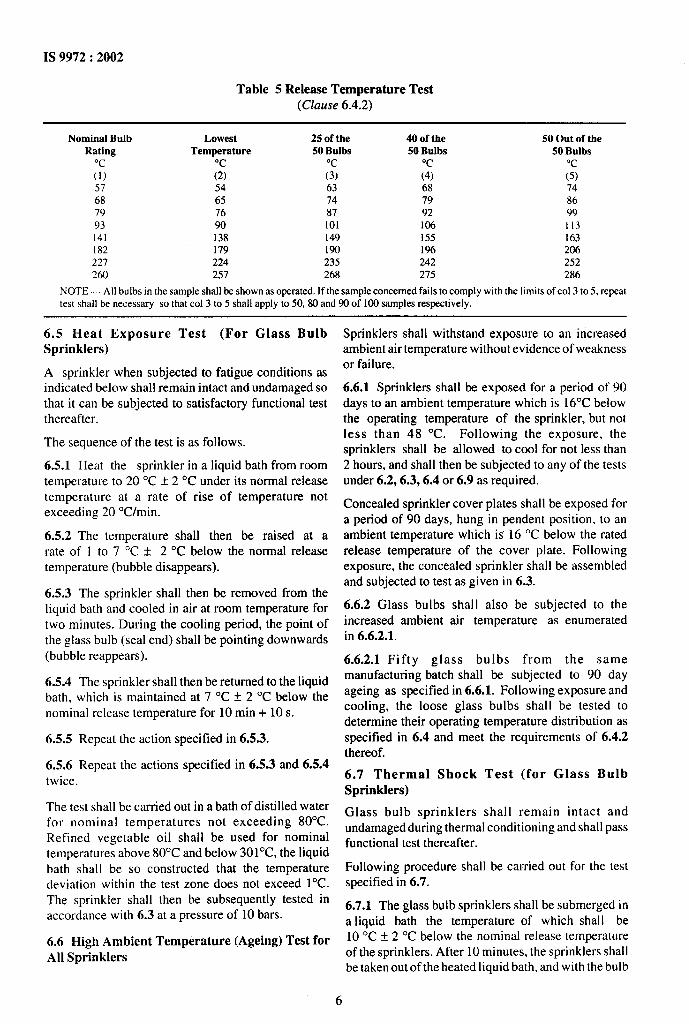
Table 5 Release Temperature Test(Clause 6.4.2)
Nominal Bulb Lowest 25 of the 40 of the 50 Out of theRating Temperature 50 Bulbs 50 Bulbs 50 Bulbs
“c “c(1) ;$ ;; ;; (5)57 54 63 68 7468 65 74 79 8679 76 87 92 9993 90 101 106 113141 138 149 155 163182 179 190 196 206227 224 235 242 252260 257 268 275 286
NOTE — All bulbsin the sample shall be shown as operated. If the sample concerned fails to comply with the limits of col 3 to 5, repeattest shall be necessary so that co] 3 to 5 shall apply to 50, 80 and90 of 100 samplesrespectively.
6.5 Heat Exposure Test (For Glass BulbSprinklers)
A sprinkler when subjected to fatigue conditions asindicated below shall remain intact and undamaged so
that it can be subjected to satisfactory functional testthereafter.
The sequence of the testis as follows.
6.5.1 Heat the sprinkler in a liquid bath from roomtemperature to 20 “C * 2 ‘C under its normal releasetemperature at a rate of rise of temperature notexceeding 20 OC/min.
6.5.2 The temperature shall then be raised at arate of 1 to 7 “C * 2 ‘C below the normal releasetemperature (bubble disappears).
6.5.3 The sprinkler shall then be removed from theliquid bath and cooled in air at room temperature fortwo minutes. During the cooling period, the point ofthe glass bulb (seal end) shall be pointing downwards(bubble reappears).
6.5.4 The sprinkler shall then be returned to the liquidbath, which is maintained at 7 ‘C i 2 “C below thenominal release temperature for 10 min + 10s.
6.5.5 Repeat the action specified in 6.5.3.
6.5.6 Repeat the actions specified in 6.5.3 and 6.5.4twice.
The test shall be earned out in a bath of distilled waterfor nominal temperatures not exceeding 80”C.Refined vegetable oil shall be used for nominaltemperatures above 80°C and below 301”C, the liquidbath shall be so constructed that the temperaturedeviation within the test zone does not exceed l“C.The sprinkler shall then be subsequently tested inaccordance with 6.3 at a pressure of 10 bars.
6.6 High Ambient Temperature (Ageing) Test forAll Sprinklers
Sprinklers shall withstand exposure to an increasedambient air temperature without evidence of weaknessor failure.
6.6.1 Sprinklers shall be exposed for a period of 90days to an ambient temperature which is 16°C belowthe operating temperature of the sprinkler, but notless than 48 ‘C. Following the exposure, thesprinklers shall be allowed to cool for not less than2 hours, and shall then be subjected to any of the testsunder 6.2,6.3,6.4 or 6.9 as required.
Concealed sprinkler cover plates shall be exposed fora period of 90 days, hung in pendent position, to anambient temperature which is 16 “C below the ratedrelease temperature of the cover plate. Followingexposure, the concealed sprinkler shall be assembledand subjected to test as given in 6.3.
6.6.2 Glass bulbs shall also be subjected to theincreased ambient air temperature as enumeratedin 6.6.2.1.
6.6.2.1 Fifty glass bulbs from the samemanufacturing batch shall be subjected to 90 dayageing as specified in 6.6.1. Following exposure andcooling, the loose glass bulbs shall be tested todetermine their operating temperature distribution asspecified in 6.4 and meet the requirements of 6.4.2thereof.
6.7 Thermal Shock Test (for Glass BulbSprinklers)
Glass bulb sprinklers shall remain intact andundamaged during thermal conditioning and shall passfunctional test thereafter.
Following procedure shall be carried out for the testspecified in 6.7.
6.7.1 The glass bulb sprinklers shall be submerged ina liquid bath the temperature of which shal I be10 “C f 2 ‘C below the nominal release temperatureof the sprinklers. After 10 minutes, the sprinklers shallbe taken out of the heated liquid bath, and with the bulb
.,
.
6

seal downwards, submerged in a water bath,maintained at a temperature of 10 “C f 1 “C for 10 to15 s. The sprinklers shall then be stabilized at roomtemperature before being tested in accordance with 6.3at a pressure as stated therein.
6.8 Strength of Heat Sensitive Element Test
The heat sensitive elements, that is, glass bulbs orfusible elements shall withstand the maximum designload for a specified period without any damage orrepairs.
6.8.1 Glass Bulb Sprinklers
The average strength of the bulb release element shallbe at least 6 times the average service load of thesprinkler when tested as specified in 6.8.1.1.
6.8.1.1 Bulbs shall be subjected to an increasing forceapplied at a rate of 250 f 10 N/s until fracture. Themethod of mounting of the bulb in the sprinkler shallbe utilized when mounting the bulb in the test rig. Ifnecessary the bulb mountings may be reinforcedexternally to prevent collapse.
6.8.2 Fusible Element Sprinklers
Fusible heat responsive element shall be designed tosustain a load of 15 times its design load correspondingto a maximum service load as determined in 6.9 or thatstated by the manufacturer, whichever is greater, for aperiod of 100 hours.
Sample heat responsive elements shall be subjected toloads in excess of the design load corresponding to Ld,the maximum service load, as determined in 6.9 whichwill produce failure for times up to or greater than1000 hours. At least 10 specimens shall be loaded atdifferent values up to 15 times the design load. A‘least squares’ full logarithmic regression curve is tobe determined from which l%, the load at one hour andL~, the load at 100 hours are to be calculated. Thefollowing condition shall be satisfied:
Lm> .99(& -~)o”5
The test samples are to be loaded at a conditionedtemperature of20°C13“C.
6.9 Service Load Measurement
The service load shall be measured by securelyinstalling the sprinkler at a stable room temperature ina test rig and applying a hydraulic pressure of 12 barsat the inlet. A linear gauge shall be attached to the testmachine and a reading shall be taken at the deflectorend of the sprinkler frame whilst under the hydraulicpressure.
The hydraulic pressure shall then be released and theheat responsive element of the sprinkler shall beremoved. A second reading of the linear gauge shallbe taken. A mechanical load shall then be applied
IS 9972:2002
to the sprinkler, progressively increasing at a rateof not exceeding 1500 N/rein, until the linear gaugereading at the sprinkler deflector returns to the initialvalue achieved under hydrostatic load. Themechanical load necessary to achieve this shall berecorded as a service load.
6.10 Strength of Frame Test
The sprinkler frame shall not develop a permanentelongation of more than 0.2 percent of the distancebetween the load bearing points when subjected tomechanical loads.
The load on the sprinkler shall be increasedprogressively at a rate not exceeding 1 500 N/rein,until twice the service load (see 6.9) has been reached.This loading shall be maintained for 10 to 15 s. Theload shall then be removed and any permanentelongation of the deflector and of the sprinkler frameshall be recorded.
6.11 Deflector Strength Test
Sprinkler deflectors shall be capable of withstandinga force without permanent deformation.
6.11.1 Sprinkler deflectors shall be capable ofwithstanding a force of 190 N without any permanentdeformation. The force shall be applied at a rate of 30N/s by means of a rigid flat metal edge and wherepossible shall form a line contact at least 15 mm longwith the deflector.
Distortion by tine or tines by a force of less than190 N applied at any point of direction, is acceptableproviding the distortion does not impair the release ofthe sprinkler operating mechanism, and thedistribution test requirements specified in 6.13.
6.11.2 There shall be no deterioration of the sprinklerperformance after a continuous water flow through theopen sprinkler at a supply pressure of 10 bars ~ 1 barfor 90 min * 5 min. Sprinklers with detachedcomponents shall be capable of satisfying thedistribution tests specified in 6.13 after the test.
6.12 Water Flow Test
6.12.1 Water Flow Test (Normal)
The discharge coefficient or K factor of a sprinklershall have the values as given in Table 6.
Table 6 Water F1OWTest(Clause 6.12.1)
Designated Discharge K Factor for DryNominal Orifke Coetllcient K SprinklersDiameter (mm)
(1) (2) (3)10 57*3 57*515 80*4 80k920 15*6 115 *9
----
1, >
,.
7

IS 9972:2002
At ambient temperature conditions, the water flow ofthe sprinkler is calculated by the formula
Q = #.5
whereQ = water flow(l/min),
P = pressure (bars), andK = flow constant.
The sprinkler minus deflector and yoke arms shall bemounted, together with a pressure gauge, on a supplypipe (see Fig. 2). The water flow shall be measuredat pressures between 0.5 bar and 6.5 bars at intervalsof 1bar. Two sets of measurements shall be taken, withpressures increasing from zero and with pressuresreducing from above 6.5 bars. An average value of Kfactor shall be measured from each set of readings, thatis, rising pressure and falling pressure. In each case theK factor shall conform with the values given in Table6. It is acceptable to adjust the pressures fordifferences in height between the gauge and thesprinkler outlet orifice. The flow test shall be carriedout at ambient temperature f 5“C.
6.12.2 Water Flow Endurance Test
An automatic sprinkler shall withstand for 30 rein,without evidence of cracking, deformation, orseparation of any part, a water flow at a pressure equal
to the maximum rated pressure plus 1.5 bars. Onesample of an automatic sprinkler shall be installed onan elbow in a pressurized system. The heat responsiveelement of the sprinkler shall be activated, and thesprinkler subjected to water flow at the above specifiedpressure for 30 min.
6.13 Water Distribution Test
6.13.1 Conventional, Spray and Dry Sprinklers
Distribution tests shall be carried out using squarearrays of 4 sprinklers over 100 equal sized pans atambient conditions of 20 ‘C t 15 ‘C. In a test room ofa size 7.5 m 10.5 m and a height of 3.2 m * 25 mm, 4sprinklers of the same type shall be installed, arrangedin a square array, on piping constructed for thepurpose. The arrangement of the piping and measuringcontainers is shown in Fig. 3, 4, 5 and 6. The yokearms of the sprinklers shall be in line with the rangepipes. The distance between the ceiling and the centreof the range pipe shall be 165 mm f 20 mm. Flush,recessed and concealed sprinklers shall be mounted ina simulated false ceiling.
The size of the protected area and the density of thecoverage for each of the three nominal sizes ofsprinkler are specified in Table 7. The number of lowcontent containers shall not exceed that stipulated inco] 6 of Table 7.
Table 7 Water Distribution Test(Clause 6.13.1)
Nominal Orifice Water Coverage, Nominat Flow Rate Nominal Protected Sprinlder Spaang Allowable LowDiameter, mm t/m/m2 per Sprinkter, I/m Area, m2
(1) (2)Content Container
(3) (4) (:) (6)10 2.5 50.6 21 4.5 815 5.0 61.3 12 3.5 515 15.0 135.0 9 3.0 420 10.0 90.0 9 3.0 420 30.0 187.5 6.25 2.5 3
Q/ PRESSURE GAUGE
(ACCURACY*2%)
MEDIUM TUBENOMINAL BORE 4 LO
‘200+ &zoo*# VALVEAIR BLEEO
PLUG ORCAP
+“0” + ,,TTINGp+-’
FIG. 2 TEST APPARATUSFOR WATER FLOW
8

I &$
IS 9972:2002
~’m ““’8”‘ax’ ●
-i
f45.
—
\
\NOMINAL BORE
C# 25 mm
7m min.
Jm max
/l- 2-25m 2.25 m--l
/ COLLECTING CANS(05mx05m)
I
t
\ME-jluM TUBE
NOMINAL BORE #65mm
WATER FLOW
FIG. 3 LAYOUTFOR WATER DISTRIBUTIONCOLLECTIONROOM (MEASUREDAREA 20.25mz)
The water distribution shall be collected in squarecontainers of side measuring 0.5 m * 10 mm. Thedistance between the ceiling and the upper edge of thecontainers shall be 2.7 m * 25 mm. The containersshall be positioned centrally in the room under the 4sprinklers.
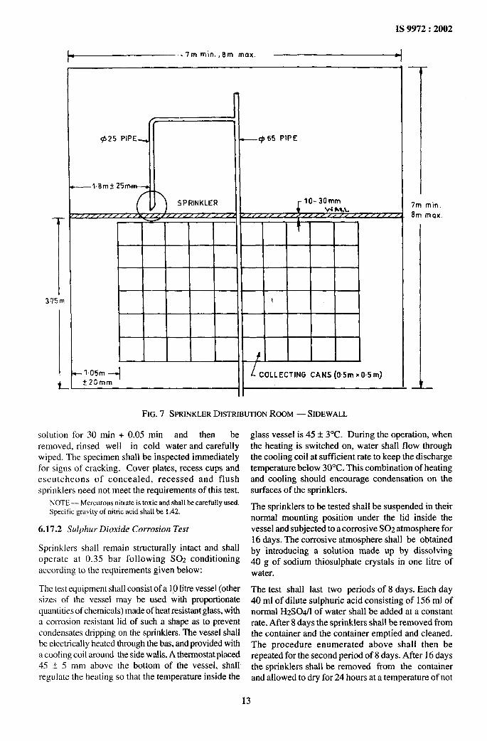
6.13.2 Sidewall Sprinklers (15 mm)
The tests shall be made in a room measuring3.75 m x 7.0 m x 3.21 m. One sprinkler shall bemounted in an appropriate position on a distribution
pipe passing through one wall so that the sprinklercentre line is situated 50 mm from that wa]l and at adistance of 1.8 m from an adjacent wall. For an uprightsprinkler, the deflector of the sprinkler shall be100 mm below the ceiling and for a pendent sprinkler150 mm below the ceiling (see Fig. 7 and 8). Watershall be collected in cans having square open tops
measuring 0.5 m x0.5 m array with its edges 1 m fromthe adjacent wall and 10 mm from the sprinklermounting wall. With the sprinkler discharging at60 l/rein, the discharge density into each can shall bedetermined and the height of the boundary between thewetted and the unwetted parts of the absorbent s[ripshall be measured. The distribution of water and wallwetting in an area bounded by two sprinklers 3.7 mapart is derived by overlapping two identical wallwetting profiles and distributions obtained from onetest using single sprinkler.
The testing shall be considered as satisfactory ifnot more than 10 percent of the bounded areareceives less than 1.125 l/rein. In addition, wetting ofthe adjacent and opposite walls shall be achievedto a height of 1 m below the level of the sprinklerdeflector.
- ---’
9

IS 9972:2002
7mmin. ,8m max .
T3.5m
NOMINAL BORE @25mm
\ \
\/
b
-==E=-T NOMINAL BORE +65mm
WATER FLOW
:7 m mom.
8m max
FIG. 4 LAYOUTOF WATER DISTRIBUTIONCOLLECTIONROOM (MEASUREDAREA 12.25m’)
6.13.3 Water Distribution Above and Below theSprinkler Dejlector (Not Applicable to Sidewall.$prinkler.s)
The water discharge of sprinklers downwards from thedeflectors shall be 40 percent to 60 percent forconventional sprinklers and 80 percent to 100 percentfor spray sprinklers. Sprinklers shall be installedhorizontally in a testing rig and the features of whichare shown in Fig 9.
The deflector is positioned within the apparatus, suchthat a theoretical dividing line between the twocollecting volumes intersects a point on the axis of thesprinkler where the water spray is travelingsubstantially parallel to the plane of the partition. (Theresults shall be given assuming that the conventionalsprinkler is mounted in the upright position).
Sprinklers shall be tested under flow conditions asshown in Table 8.
Table 8 Flow Condition forWater Distribution Test
(Clause 6.13.3)
Nominal Orifice Sprinkler WaterDiameter, mm Flow Rate, I/m
(1) (2)
10 5015 60
20 90
6.14 Water Hammer Test
When tested as detailed in the procedure below,the sprinkler shall :
a) experience no leakage when subjectedto3000applications of a pressure surge increasingrapidly from 3.5 bars to 35 bars;
b) not leak when subjected to a pressure of 35 barsfor one minute, following 3000 cycles of waterhammer; and
10

IS 9972:2002
~’m ““8”‘ax” ●
NOMINAL BORE
\
4 25mm
l+- 15m — _l.5m+
1A MEDtUM TUBENOMINAL BORE q565mm
WATER FLOW
lm min.
)m max.
r—
FIG. 5 LAYOUTOF WATER DISTRIBUTIONCOLLECTIONROOM (MEASUREDAREA 9.0 mz)
c) show no distortion or other physical damagefollowing the water hammer testing as deter-mined by visual examination.
6.14.1 Sprinkler samples shall be installed in awater filled test line connecting with a small motoroperated piston pump that produces a rapid rise indischarge pressure from 3.5 to 35 bars at the rate of60 cycles /min. The test piping shall be filled so thatthere is water at the sprinkler seat, and the pump is tobe placed in operation and adjusted to produce thespecific test pressure cycle.
6.14.2 During pressure cycling, observations shall bemade for the evidence for leakage, if any.
6.14.3 Following the completion of the pressurecycling, the samples are to be tested to verify that theydo not leak at 35 bars pressure. The pressure shall beincreased to 35 bars at a rate not exceeding 20 barsa minute. The pressure shall be maintained at 35
bars for a minute and then released at a rate notexceeding 20 bars a minute to O. The samples shallthen be physically checked to verify evidence ofdistortion.
6.15 Vibration Test
6.15.1 Automatic sprinklers shall withstand theeffects of vibration without deterioration of itsperformance characteristics. The sprinkler shhll besubjected to a vibration of lmm amplitude for 120hours at a frequency that is continuously variedbetween 18 to 37 Hz. However, if the sprinklersexhibit resonance at a frequency within this range, theresonant frequency shall be used throughout the testperiod. Following the vibration test, the sprinkler shallcomply with leakage test as specified in 6.2.
6.15.2 This test shall be conducted with the testsprinklers unpressurized.
11

IS 9972:2002
~’m ““$8” ‘“x●
2.5 m
1
\
NOMINAL BORE+25mm
+“”-+’25. --1
I > MEDIUM TUBE
t
NOMINAL BORE +65mm
WATER F LOW
i
7m mln,
Bm max.
FIG. 6 LAYOUTFORWATER DISTIUBUTIONCOLLECTIONROOM (MEASURED AREA 6.25 mz)
6.15.3 For these tests, amplitude is defined as themaximum displacement of sinusoidal motion from theposition of rest to one-half of the total tabledisplacement; resonance is defined as the maximummagnification of the applied vibration.
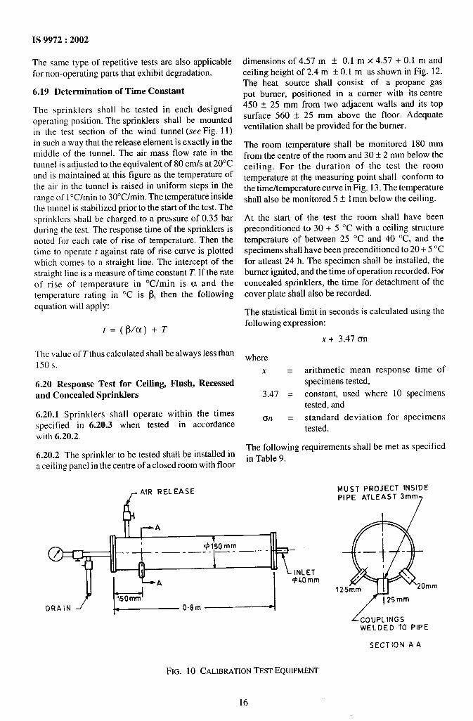
6.16 Calibration Test
Sprinkler sample shall be flow tested first at a pressureof 0.5 bar and then at 0.7 bar. Following this, thepressure is to be increased in 0.5 bar increments up to3.5 bars, in 0.7 bar increments upto 7 bars, decreasedin 0.7 bar increments down to 3.5 bar, in 0.5 barincrements down to 0.7 bar and then decreased to 0.5bar. The flow at each increment of pressure is to bemeasured by a flow measuring device having anaccuracy of within 2 percent of the actual flow. Thedischarge coefficient shall be calculated using theequation K= QP+”5 (see 6.12.1) and the average value
of K shall be calculated. The value of K shall be as perthe details given in Table 6.
The details of the equipment for the above test isshown in Fig. 10.
6.17 Corrosion Tests
6.17.1 Mercurous Nitrate Stress Corrosion Test
As a result of the test described below, copper alloycomponents used in the construction of sprinklel-s shallnot crack. The specimen for the test shall be degreasedand then immersed in a solution of 50 percent distilledwater and 50 percent concentrated nitric acid forbetween 21 to 24s. The specimen shall then be rinsedin cold water and immersed in one percent by weightsolution of mercurous nitrate in distilled water towhich one percent by volume of concentrated nitricacid has been added. The specimen shall remain in the
---.
., . .
12
IS 9972:2002
~’m”’in””m ‘“x” 4—
II
h- 1.05mi
f20mmII 1COLLECTING CANS (05m x 05 m)
7m
8mmin.
max.
II
FtG. 7 SPRINKLERDISTRIBUTIONROOM — SIDEWALL
solution for 30 min + 0.05 min and then be glass vessel is 45 i- 3“C. During the operation, whenremoved, rinsed well in cold water and carefully the heating is switched on, water shall flow throughwiped. The specimen shall be inspected immediately the cooling coil at sufficient rate to keep the dischargefor signs of cracking. Cover plates, recess cups and temperature below 30”C. This combination of heatingescutcheons of concealed, recessed and flush and cooling should encourage condensation on thesprinklers need not meet the requirements of this test. surfaces of the sprinklers.
NOrE — Mercurous nitrate is toxic and shall be carefully used.Specific gravity of nitric acid shall be 1.42.
The sprinklers to be tested shall be suspended in theirnormal mounting position under the lid inside the
6.17.2 Sulphur Dioxide Corrosion Test vessel and subjected to a corrosive S02 atmosphere for16 days. The corrosive atmosphere shall be obtained
Sprinklers shall remain structurally intact and s~ll by introducing a solution made up by dissolving
operate at 0.35 bar following S02 Conditicmmg 40 g of s~ium thiosulphate crystals in one litre ofaccording to the requirements given below: water.
The test equipment shall consist of a 10 litre vessel (othersizes of the vessel may be used with proportionatequantities of chemicals) made of heat resistant glass, witha corrosion resistant lid of such a shape as to preventcondensates dripping on the sprinklers. The vessel shallbe electrically heated through the has, and provided witha cooling coil around the sidewalls. A thermostat placed45 t 5 mm above the bottom of the vessel, shall
regulate the heating so that the temperature inside the
The test shall last two periods of 8 days. Each day40 ml of dilute sulphuric acid consisting of 156 ml ofnormal I-12S04/l of water shall be added at a constantrate. After 8 days the sprinklers shall be removed fromthe container and the container emptied and cleaned.The procedure enumerated above shall then berepeated for the second period of 8 days. After 16 daysthe sprinklers shall be removed from the containerand allowed to dry for 24 hours at a temperature of not
13

---4IS 9972:2002
...—
+25mm PIPE
FIG. 8 MOUNTINGOF SIDEWALLSPRINKLERS— DISTRIBUTION
exceeding 35 ‘C with a relative humidity of not morethan 70 percent before being functionally tested asgiven in 6.3 at 0.35 bar.
6.18 Stress Corrosion Cracking Test
6.18.1 For Sprinklers with Brass Parts
A sprinkler having brass parts shall:a) show no evidence of cracking, delamination or
degradation, orb) demonstrate acceptable performance after
being subjected for 10 days to a moistammonia exposure.
Samples of sprinklers shall be degreased andthen exposed for 10 days to a moist ammonia airmixture maintained in a glass chamber approximately300 mm x 300 mm x 300 mm having a glass cover. A
small amount of aqueous ammonia having a specificgravity of 0.94 is to be maintained in the bottom of thechamber, approximately 38 mm below the bottom ofthe samples. The moist ammonia air mixture in thechamber is to be maintained at essentially atmosphericpressure with the temperature constant atapproximately 35 ‘C. The aqueous ammonia,temperature and pressure provide approximately33.4 percent by volume of ammonia and 3.9 percentby volume of water vapour above the liquid inchamber, the remaining 62.7 percent by volume beingair.
After the exposure period, the test samples are to beexamined using a microscope having a magnificationof 25 x for any cracking, delamination or otherdegradation as a result of the test exposure. Operatingparts exhibiting degradation as a result of the testexposure described as above shall withstand withoutany leakage a hydrostatic pressure of 12 bars or oneequivalent to their maximum design pressurewhichever is greater for one minute and operate at 0.5bar when exposed to a uniform application of heat. Ifthe samples have any cracking, delamination, ordegradation of non operating parts as a result of thetest exposure, they shall withstand a flowing pressureof 12 bars for 30 min.
6.18.2 For Sprinklers With Stainless Steel Parts
A sprinkler having stainless steel parts shall:a) show no evidence of cracking, delamination or
degradation; orb) demonstrate acceptable performance after
being subjected to boi!ing magnesium chloridesolution.
Samples shall be degreased prior to the exposure toboiling magnesium chloride solution. Parts used in thesprinklers shall be placed in a 500 ml flask that is fittedwith a thermometer and a wet condenserapproximately 750 mm long. The flask is to be filledabout one-half full with a 42 percent by weightmagnesium chloride solution, placed on athermostatically controlled electrically heated mantel
.. ----
14

IS 9972:2002
T PARTITION
II
\ ~-----,---y
1/1
I .-’ Ii .’ -W ------ -- ------ --
.“//“/
.“”0.
FIG. 9 APPARATUSFORDETERMININGWATER DISTRIBUTIONABOVE ANDBELOWTHE DEFLECTOR
and maintained at a boiling temperature of 150 ‘C+ 1 ‘C. The parts are to be unassembled, that is, not—contained in a sprinkler assembly. The exposure is tolast for 150 h in case of sprinklers to be used in noncorrosive atmosphere and for 500 h in case ofsprinklers to be used in corrosive atmosphere.
After the exposure period, the test samples shall beremoved from the boiling magnesium chloridesolution and rinsed in de-ionized water.
After the exposure period, the test samples are to beexamined using a microscope having a magnificationof 25 x for any cracking, delamination or otherdegradation as a result of the test exposure. Testsamples not exhibiting degradation are to beconsidered acceptable without further test.
Operating parts exhibiting degradation shall be testedfurther by assembling five new sets of parts insprinkler frames made of materials that do not alter thecorrosive effects of the magnesium chloride solutionon the stainless steel parts. These samples shall betested in the same fashion as specified above and afterthe test the samples shall withstand without anyleakage a hydrostatic pressure of 12 bars or oneequivalent to their maximum design pressurewhichever is greater for one minute and operate at 0.5bar when exposed to a uniform application of heat. Ifthe samples have any cracking, delamination, ordegradation of non-operating parts as a result of thetest exposure, they shall withstand a flowing pressureof 12 bars for 30 min.
15
IS 9972:2002
The same type of repetitive tests are also applicable
for non-operating parts that exhibit degradation.
6.19 Determination of Time Constant
The sprinklers shall be tested in each designedoperating position. The sprinklers shall be mountedin the test section of the wind tunnel (see Fig. 11)in such a way that the release element is exactly in themiddle of the tunnel. The air mass flow rate in thetunnel is adjusted to the equivalent of 80 crrds at 20°Cand is maintained at this figure as the temperature ofthe air in the tunnel is raised in uniform steps in therange of 10C/min to 30°C/min. The temperature insidethe tunnel is stabilized prior to the start of the test. Thesprinklers shall be charged to a pressure of ().35 barduring the test. The response time of the sprinklers isnoted for each rate of rise of temperature. Then thetime to operate t against rate of rise curve is plottedwhich comes to a straight line. The intercept of thestraight line is a measure of time constant T. If the rateof rise of temperature in OC/min is o. and thetemperature rating in “C is ~, then the following
equation will apply:
f=(~/cY. )+7-
The value of Tthus calculated shall be always less than150 s.
6.20 Response Test for Ceiling, Flush, Recessedand Concealed Sprinklers
6.20.1 Sprinklers shall operate within the timesspecified in 6.20.3 when tested in accordancewith 6.20.2.
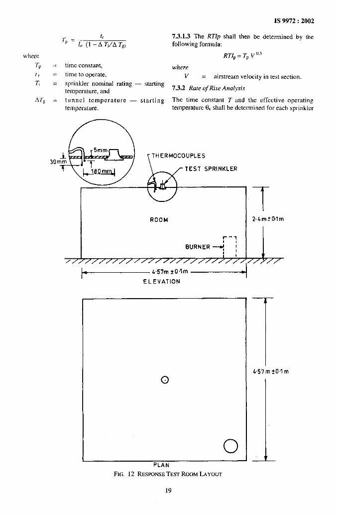
6.20.2 The sprinkler to be tested shall be installed ina ceiling panel in the centre of a closed room with floor
dimensions of 4.57 m f 0.1 m x 4.57 + 0.1 m andceiling height of 2.4 m f 0.1 m as shown in Fig. 12.The heat source shall consist of a propane gaspot burner, positioned in a comer with its centre450 * 25 mm from two adjacent walls and its topsurface 560 * 25 mm above the floor. Adequateventilation shall be provided for the burner.
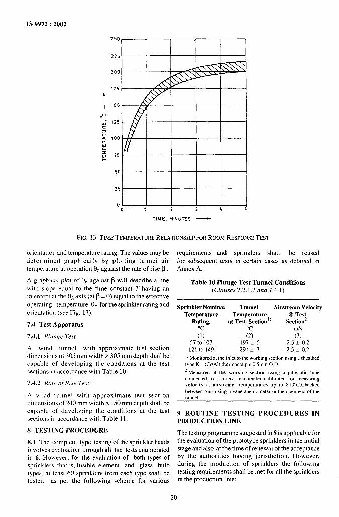
The room temperature shall be monitored 180 mmfrom the centre of the room and 30 f 2 mm below theceiling. For the duration of the test the roomtemperature at the measuring point shall conform tothe time/temperature curve in Fig. 13. The temperatureshall also be monitored 5 t 1mm below the ceiling.
At the start of the test the room shall have beenpreconditioned to 30 + 5 ‘C with a ceiling structuretemperature of between 25 “C and 40 “C, and thespecimens shall have been preconditioned to 20 + 5 “Cfor atleast 24 h. The specimen shall be installed, theburner ignited, and the time of operation recorded. Forconcealed sprinklers, the time for detachment of thecover plate shall also be recorded.
The statistical limit in seconds is calculated using thefollowing expression:
x+ 3.47 cm
where
x= arithmetic mean response time ofspecimens tested,
3.47 = constant, used where 10 specimenstested, and
cm = standard deviation for specimenstested.
The following requirements shall be met as specifiedin Table 9.
LAIR RELEASE MUST PROJECT INSIDE
PIPE ATLEAST 3mm
1
~COUPLINGSWELDED TO PIPE
SECTION AA
FIG. 10 CALIBRATIONTEST EQUIPMENT
16
- ---“
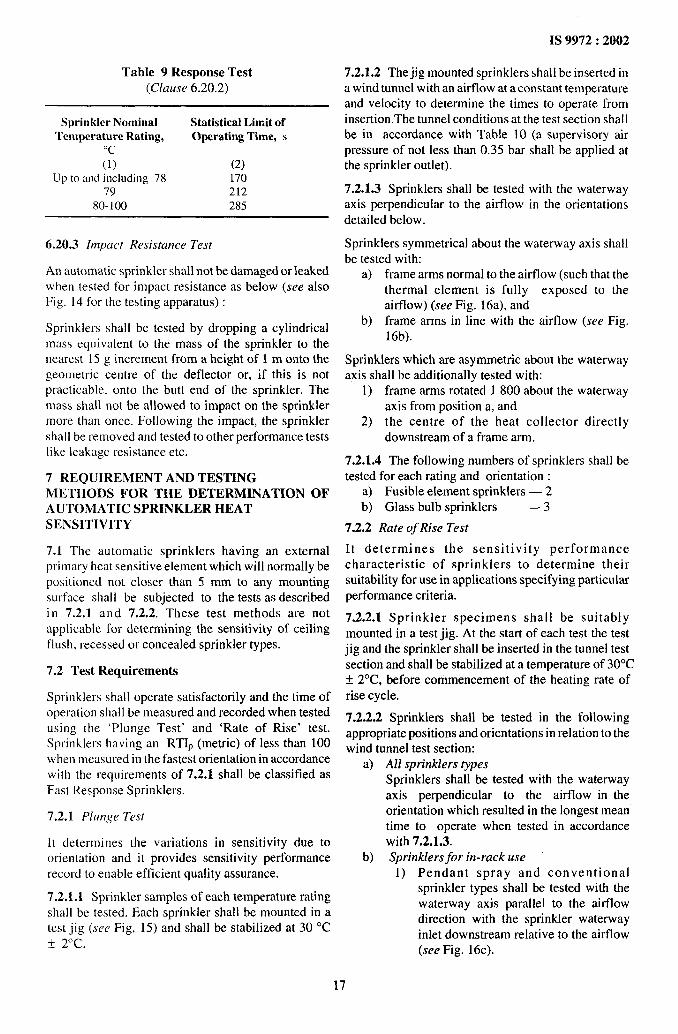
Table 9 Response Test
(Clause 6.20.2)
Sprinkler Nominal Statistical Limit ofTemperature Rating, Operating Time, s
“c(1) (2)
Up to and including 78 17079 212
80-100 285
6.20.3 Impuct Resistance Test
An automatic sprinkler shall not be damaged or leakedwhen tested for impact resistance as below (see alsoFig. 14 for the testing apparatus) :
Sprinklers shall be tested by dropping a cylindricalmass equivalent to the mass of the sprinkler to thenearest 15 g increment from a height of 1 m ontQ thegeometric centre of the deflector or, if this is notpracticable, onto the butt end of the sprinkler. Themass shall not be allowed to impact on the sprinklermore than once. Following the impact, the sprinklershal 1be removed and tested to other performance testslike leakage resistance etc.
7 REQUIREMENT AND TESTINGMETHODS FOR THE DETERMINATION OFAUTOMATIC SPRINKLER HEATSENSITIVITY
7.1 The automatic sprinklers having an externalprimary heat sensitive element which will normally bepositioned not closer than 5 mm to any mountingsurface shall be subjected to the tests as describedin 7.2.1 and 7.2.2. These test methods are notapplicable for determining the sensitivity of ceilingflush, recessed or concealed sprinkler types.
7.2 Test Requirements
Sprinklers shall operate satisfactorily and the time ofoperation shal 1be measured and recorded when testedusing the ‘Plunge Test’ and ‘Rate of Rise’ test.Sprinklers having an RTIP (metric) of less than 100when measured in the fastest orientation in accordancewith the requirements of 7.2.1 shall be classified asFast Response Sprinklers.
7.2.1 Plunge Test
It determines the variations in sensitivity due toorientation and it provides sensitivity performancerecord to enable efficient quality assurance.
7.2.1,1 Sprinkler samples of each temperature ratingshall be tested. Each sprinkler shall be mounted in atest jig (see Fig, 15) and shall be stabilized at 30 ‘C+ 2°c.—
IS 9972:2002
7.2.1.2 The jig mounted sprinklers shall be inserted ina wind tunnel with an airflow at a constant temperatureand velocity to determine the times to operate frominsertion. The tunnel conditions at the test section shallbe in accordance with Table 10 (a supervisory airpressure of not less than 0.35 bar shall be applied atthe sprinkler outlet).
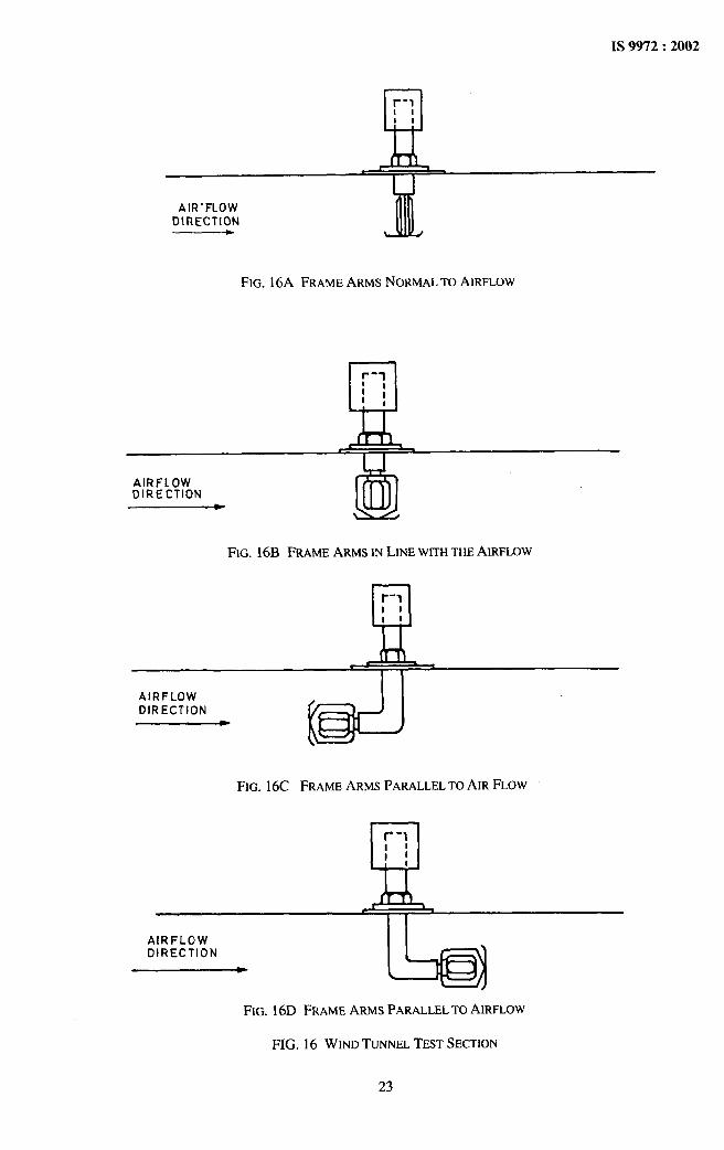
7.2.1.3 Sprinklers shall be tested with the waterwayaxis perpendicular to the airflow in the orientationsdetailed below.
Sprinklers symmetrical about the waterway axis shallbe tested with:
a) frame arms normal to the airflow (such that thethermal element is fully exposed to theairflow) (see Fig. 16a), and
b) frame arms in line with the airflow (see Fig.16b).
Sprinklers which are asymmetric about the waterwayaxis shall be additionally tested with:
1) frame arms rotated 1800 about the waterwayaxis from position a, and
2) the centre of the heat collector directlydownstream of a frame arm.
7.2.1.4 The following numbers of sprinklers shall betested for each rating and orientation :
a) Fusible element sprinklers — 2b) Glass bulb sprinklers — 3
7.2.2 Rate of Rise Test
It determines the sensitivity performancecharacteristic of sprinklers to determine theirsuitability for use in applications specifying particularperformance criteria.
7.2.2.1 Sprinkler specimens shall be suitablymounted in a test jig. At the start of each test the testjig and the sprinkler shall be inserted in the tunnel testsection and shall be stabilized at a temperature of 30°C~ 2“c, before commencement of the heating rate of
rise cycle.
7.2.2.2 Sprinklers shall be tested in the foilowingappropriate positions and orientations in relation to thewind tunnel test section:
a) All sprinklers typesSprinklers shall be tested with the waterwayaxis perpendicular to the airflow in theorientation which resulted in the longest meantime to operate when tested in accordancewith 7.2.1.3.
b) Sprinklers for in-rack use1) Pendant spray and conventional
sprinkler types shall be tested with thewaterway axis parallel to the airflowdirection with the sprinkler waterwayinlet downstream relative to the airflow(see Fig. 16c).
17

IS 9972:2002
%
1.
2.3.4.5.6.7,8.
-lb305 mm
SECTION AA
Control panel with nine switches for coarse control and autotransformer for fine control ofheaters in 2.Heater compartment with ten 1 kW heater elements.74,6 W 2850 rev/rein motor blower.Manual control for shutter controlling air flow.Removalable asbestos sheet covers.Cover of sprinkler test compartment with glass inspection window.Exhaust port.Inlet port coupled to exhaust port to facilitate rapid cooling.
FIG. 11 WIND TUNNEL
2) Upright spray and conventionalsprinklers shall be tested with the water-way axis parallel to the airflow directionwith the waterway inlet upstream rela-tive to the airflow (see Fig. 16d).
7.2.2.3 Prior to the start of the test the sprinklerpipework shall be filled with a specified volume ofwater above the sprinkler inlet.
7.2.2.4 Sprinkler specimens of each rating shall betested in the wind tunnel in the appropriate positionsand orientations described at 7.2.2.2 and shall besubjected to a steadily increasing airstreamtemperature at a constant mass flow. Tests shall beundertaken at the following rates of temperature rise:
a) 2° C/rein,b) 12° C/rein, andc) 20° C/rein.
The sprinkler operating time shall be measured frominitiation of the rate of rise, starting at a stablecondition of 30”C.
7.2.2.5 The following numbers of sprinklers shall betested for each temperature rating, position and rate ofrise:
a) Fusible bulb sprinklers —2b) Glass bulb sprinklers —3
7.3 Analysis of Test Results
7.3.1 Plunge Test Results Analysis
7.3.1.1 The arithmetic mean time to operate eachsprinkler rating at each orientation shall bedetermined.
7.3.1.2 The time constant for each sprinkler rating atany orientation may be determined by the formula:
18
TP =t~
1,, (1 – A Ti/A T~)
where
TP = time constant,
t~ = time to operate,
T, = sprinkler nominal rating — startingtemperature, and
AT~ = tunnel temperature — starting
temperature.
IS 9972:2002
7.3.1.3 The RTIp shall then be determined by thefollowing formula:
RTIP = TP V 0“5
where
v= airstream velocity in test section.
7.3.2 Rate of Rise Analysis
The time constant T and the effective operating
tempera~ure (3, shall be determined for each sprinkler
i THERMOCOUPLES30mtn
TEST SPRINKLER
ROOM
~-l
BURNER + ~I!,,
77//////// ~/// /////////// /
ELEVATION
0PLAN
FIG. 12 RESPONSETEST ROOM LAYOUT
T2.4mf0.lm
L
—
k57mt0.lm
I—
19
IS 9972:2002
t
250
225 -
200 / 7
775t A\
‘““t---z$rJJ
50 I I I 1
25 I
I
TIME, MINUTES —
FIG. 13 TIME TEMPERATURERELATIONSHIPFORROOM RESPONSE
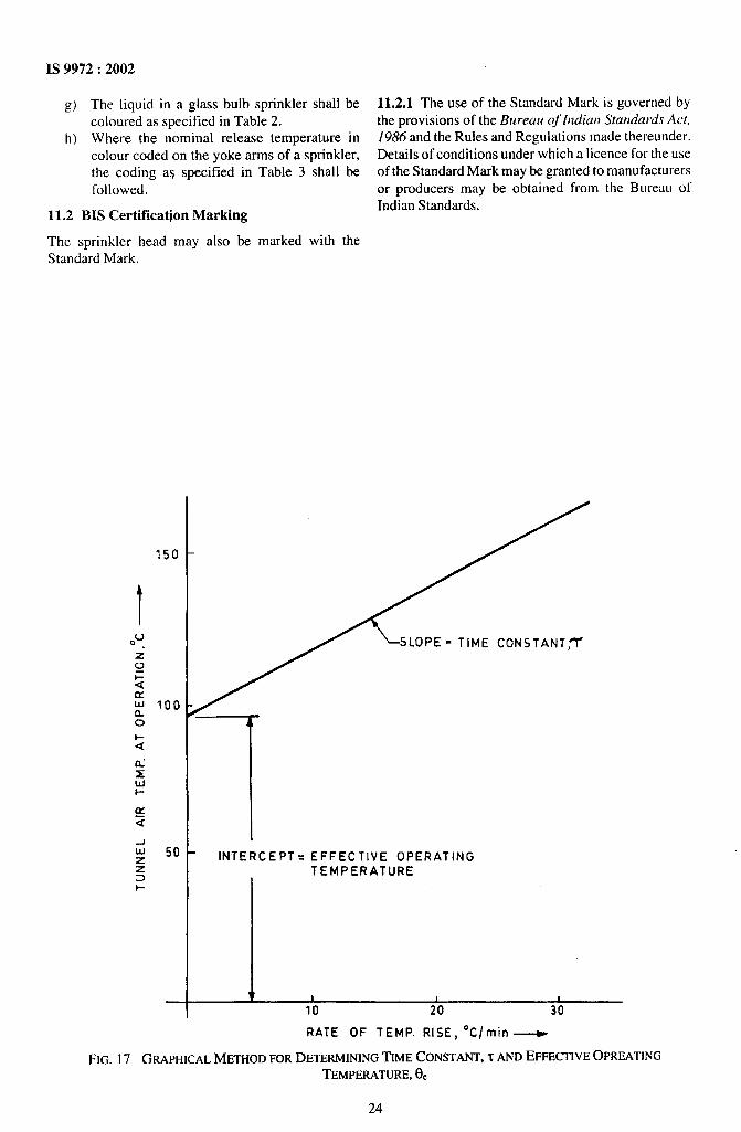
orientation and temperature rating. The values may bedetermined graphically by plotting tunnel airtemperature at operation 0~ against the rate of rise ~ .
A graphical plot of f3gagainst ~ will describe a line
with slope equal to the time constant T having anintercept at the f3gaxis (at @= O) equal to the effective
operating temperature de for the sprinkler rating and
orientation (see Fig. 17).
7.4 Test Apparatus
7.4.1 Plunge Test
A wind tunnel with approximate test sectiondimensions of 305 mm width x 305 mm depth shall becapable of developing the conditions at the testsections in accordance with Table 10,
7.4.2 Rate of Rise Test
A wind tunnel with approximate test sectiondimensions of 240 mm width x 150 mm depth shall becapable of developing the conditions at the testsections in accordance with Table 11.
8 TESTING PROCEDURE
8.1 The complete type testing of the sprinkler headsinvolves evaluation through all the tests enumeratedin 6. However, for the evaluation of both types ofsprinklers, that is, fusible element and glass bulbtypes, at least 60 sprinklers from each type shall betested as per the following scheme for various
TEST
requirements and sprinklers shal 1 be reusedfor subsequent tests in certain cases as detailed inAnnex A.
Table 10 Plunge Test Tunnel Conditions(Clauses 7.2.1.2 and 7.4.1)
Sprinkler Nominal Tunnel Airstream VelocityTemperature @ Test
Rating, a~;%%~%=’) Section’)‘c ‘c mls(1) (2) (3)
57 to 107 197 & 5 2.5 t O.Z
121 to 149 291 & 7 2.5 * 0.2
1)M~njt~red at the inlet to the working section using a sheathed
type K (Cr/Al) thermocouple 0.5mm O.D.z)Mea~ured at the working section USifYg ir @CIs~~d~ tube
connected to a micro manometer calibrated for measuringvelocity at airstream ‘temperatures up to 800°C.Checkedbetween runs using a vane anemometer in the open end of thetunnel.
9 ROUTINE TESTING PROCEDURES INPRODUCTION LINE
The testing programme suggested in 8 is applicable forthe evaluation of the prototype sprinklers in the initialstage and also at the time of renewal of the acceptanceby the authorities having jurisdiction. However,during the production of sprinklers the followingtesting requirements shall be met for all the sprinklersin the production line:
20

IS 9972:2002
COLD QRAWN SEAMLESSSTEEL TUBING lL.lt)mm [.D ~
LOCKING PIN -. ~1 :1
WE IGHTI See Detai[COLD FINISHED STEEL
LENGTH TO BE DETERMINED[FUNCTION OF REQD, WEIGHT)
P-7 ‘m
[—~fl]@Omm
DETAIL ‘A’
--t-t
SPRINKLER SUPPORT@165mm COLD FINISHEDSTEEL ~ #zIl
a) Examination of sprinklers as
I I IFIG. 14 IMPACTTEST APPARATUS
specified in 6.1, a) Leak resistance test (see 6.2),and b) Functional test (see 6.3),
b) Each automatic sprinkler shall be subjected to c) Release temperature test (see 6.4),hydrostatic test at 35 bars pressure and the d) Strength of frame test (see 6.10),pressure shall be maintained for a period of e) Water flow test (see 6.12),not less than 5 s. There shall be no leakage f) I)Distribution test (see 6.13),during the test. t%) l)Calibration test (see 6.16),
10 TEST FACILITIES EXPECTED AT THEh) ‘kesponse test (see 6.20), and
MANUFACTURERS WORKS j) l)Sensitivity test (see 7).
10.1 The manufacturer shall provide regular11 MARKING
production control, inspection and tests to maintain the 11.1 Each sprinkler shall be legibly and indelibly
quality of the sprinklers produced from time to time. ‘arked ‘ith ‘he ‘O1]Owing :For this purpose, it is necessary to provide at !east the a) Manufacturer’s name or trade-mark.
following facilities so that these tests can be carriedout at regular intervals: lThese tests are optional,
21

IS 9972:2002
n
I I
I1. Reservoir forusein’wet’ tests2. Externally threaded tube3. Locking ring4. Locating discs5. Sprinkler fitting
FIG. 15 SPRINKLERMOUNTINGJIG
Model identification to be used in conjunction c) Year of manufacture.
with the manufacturer’s catalogue. The d) Nominal release temperature.
manufacturer’s catalogue identification must e) Cover plates of the concealed sprinklers shall
define uniquely the design size, distribution be marked ‘Do not Paint’.
type and mounting position. In particular, the f,) Sprinklers shall be marked with the nominal
identification symbol used must be changed temperature rating in “C or colour code on a
where there is any significant alteration in the part of the sprinkler after operation.
shape, materials or method of manufacture.
Table 11 Rate of Rise Test Tunnel Conditions(Clause 7.4.2)
Start Temp Rate of Temp Rise Mar Temp Temperature Variation Airstream Velocity
‘c OClmin from Ideal Ramp “C in Test Section at 25°C(1) (2) :) (4) (5)
30?2 2 250 &3 lot 0.1
3012 12 250 *3
?@iz
l.oi 0.1
20 250 *3 1.0* 0.1
22
IS 9972:2002
t 1
!Ll!~-l
I11
AIR-FLOWDIRECTION
FIG. 16A FRAME ARMS NORMALTO AIRFLOW
~-l1;1,
AIRFLOWDIRECTION
FIG. 16B FRAME ARMS IN LINE WITHTHEAIRFLOW
r-lIIII
AIRFLOWDIRECTION
FIG. 16C FRAME ARMS PARALLELTO AIR FLOW
r-II
AIRFLOWDIRECTION
~L
FIG. 16D FRAME ARMS PARALLELTO AIRFLOW
FIG. 16 WIND TUNNELTEST SECTION
23
IS 9972:2002
g) The Iiquidin aglassbulb sprinkler shall becoloured as specified in Table 2.
h) Where the nominal release temperature incolour coded on the Yoke arms of a sprinkler,the coding a$ specified infollowed,
11.2 BIS Certitlcation Marking
The sprinkler head may also beStandard Mark.
Table 3 ‘shall be
marked with the
11.2.1 The use of the Standard Mark is governed bythe provisions of the Bureau of Indian Sturldards Act,J986 and the Rules and Regulations made thereunder.Details of conditions under which a licence for the useof the Standard Mark maybe granted to manufacturersor producers may be obtained from the Bureau of
Indian Standards.
SLOPE = TIME CONSTANT,~
1INTERCEPT= EFFECTIVE OPERATING
TEMPERATURE
\ 1 1 I10 20 30
----
RATE OF TEMP. RISE, OC/min ~
FIG. 17 GRAPHICALMETHOD FORDETERMININGTIME CONSTANT,7 ANDEFFECTIVEOPREATINGTEMPERATURE,ee
24

A,
IS 9972:2002
ANNEX A
(Clause 8)
QUANTITY OF SAMPLES OF SPRINKLER
No. of Sprinklers Required
S1 Typeof Test Clause Universal Upright Pendent10,
1 Tknc constant evaluation 6.19 lto4 lto4 lto4
2 Releasetemperature 6.4 50bulbs 50 bulbs 50 bulbs
3 Service load measurement 6.9 5t08 5t08 5t08
4 Strength of sprinkler frames 6.10 5t08 5t08 5t08
5 Strength of glass bulbs 6.8 9to12 9to12 9 to 12
6 Thermal shock 6.7 13, 14 13, 14 13, 14
7 Heat exposure (fatigue) 6.5 15, 16 15, 16 15, 16
8 High ambient temperature (ageing) 6.6 17 to 24 17t024 17 to 24
9 Water hammer test 6.14 19t021 19t021 19 to 21
10 Vibration test 6.15 15,16,22 15, 16,22 15, 16,22
11 Stress corrosion cracking 6.18 23,24 23,24 23,24
12 Impact resistance 6.20.3 15,23,24 15,23,24 15,23,24
13 Leak resistance 6.2.1 15 to 24 15t024 15t024
14 Leak resistance (30 days) 6.2.2 17, 18 17, 18 17, 18
15 Corrosion tests 6.17 25 to 28 25 to 28 25 to 28
16 Functional test: 6.30.35 bars upright position — 13, 17, 18,25,29 to 32 13, 15, 17, 18,25,26,29,30 —3.50 bars upright position — 15, 19,27,33 to 37 14, 16, 19,20,27,28,31,32 —7.00 bars upright position — 20,38 to 44 21 to 24,33 to 36 —
0.35 bars pendent position — 14,21,22,26,45 to48 — 13, 15, 17, 18,25,26,29,303.50 bars pendent position — 16,23,28,49 to 53 — 14, 16, 19,20,27,28,31,327.00 bars perrdent position — 24,54 to 60 — 21 to 24,33 to 36
17 Water flow test (normal) 6.12.1 33 to 36 33 to 36 33 to 36
18 Water flow test (endurance) 6.12.2 33 to 36 33 to 36 33 to 36
19 Deflector strength test 6.11 34 and 35 34 and 35 34 and 35
20 Waterdistributiontest 6.13.1and 29 to 32 29 to 32 29 to 32
6.13.2
21 Wmerdistributiontest 6.13.3 30 and31 30and 31 30 and 31
22 Calibrationtest 6.16 any three anythree any three
23 Responsetest 6.20 1,5, 12,14 1,5, 12, 14 1,5, 12, 1416,22,23, 16,22,23 16,22,2327,30,34 27,30,34 27,30,34
24 SensitivityanddeterminationofRTI index 7 Optional Optional Optional
(any 10) (any 10) (any 10)
-----
,
25

IS 9972:2002
ANNEX B
(Foreword)
COMMITTEE COMPOSITION
Fire Fighting Sectional Committee, CED 22
OrganizationFire Advisor, Ministry of HomeAffairs,NewDelhiAvon Services Pvt Ltd, Mmnbai
Bhabba Atomic Research Cerrtre, MumbaiBombay Fire Brigade, Mumbai
Central Building Research Institute (CSIR), Roorkee
Central Industrial Security Force, New Delhi
Central Public Works Department, New Delhi
Chief Fire Officer, State Bank of India, MumbaiConcord Arai Pvt Ltd, CbennaiController of Quality Assurance, Pune
Defence Research and Development Organization, New Delhi
Delhi FireService,NewDelhi
DirectorateGeneralof SuppliesandDisposals,NewDelhi
Engineer-in-ChiefsBranch,NewDelhi
Eureka~iretecbPvt Ltd,Mumbai
FireandSafetyAppliancesCo,KolkataHome Department (Fke Service), Chennai
Home (Police Department), Government of Andhra Pradesh,Hyderabad
Indian Rayon, New DelhiKooverji Devshi and Co (P) Ltd, Mumbai
K.V. Fire Chemicals, MumbaiLoss Prevention Association India, Mumbai
MECON, Ranchi
Ministry of Home Affairs, New DelhiMinistry of Defence, New Delhi
National Airport Authority, New Delhi
Newirge Industries, Gujarat
Oil & Nattiral Gas Commission, Debra Dun
Oil Industries Safety Directorate, Ministry of Petroleum andNature] Gas, New Delhi
RailwayBoard,NewDelhiRealValueAppliances,MumbaiSafexFireServices,MumbaiSteelageIndustriesLtd, Chennai,NewDelhi
Steel Authority of India Ltd, Rourkela
Steel Authority of India Ltd, Bokaro
Surex Prodution turd SaIes Pvt Ltd, Kolkata
Tariff Advisory Committee. Ahmedaba~ew Delhi
Representative(s)SHRIOM PRAKASH(Chairman)MANAGINGDIRECrGR
TECHNICALEXECUTtVE(Alternate)
CHIEFFIRE OFFICERCHIEFFrRE OFFICER
DEPUTYCHtEF FtRE OFFICER(Alternate)DR T. P. SHARMA
DR A. K. GUPTA(Akerrrafe)
SHRIR. C. SHARMASHSUS. L. NAGARKAR(Alternate)
CHIEFENGINEER(E)SHRIJ. S. GAHLAUTSHRIR. RAMAKSUSHNANSHRIJ. D. KALE
LT-COL S. C. AGARWAL(Alternate)DIRECrOR
DmJPTYDIRECTOR (Alternate)
SHRt S. K. DHERISHRISURINDERKUMAR (Alternate)
SHRIM. GANGARAJGSHRIV. K. VERMA(Alrernate)
SHRI S. K. KALIAStim M. K. BANSAL(Alternate)
SHRt S. M. DESAISHRIE. S. DEW (Alternate)
SHRIS. N. KUNDUDIRECTOR
DEPUTYDIRECTOR(Alternate)SHRtSWARANJrrSEN
DEPUTYDtRECTOR(Alternate)
SHSUS. K. SUREKASHRIP. H. SETHNA
SHRIN. T. PANJWANI(Alfemate)SHRIH. M. SABADRAMANAGINGDtRECTGR
SHRI D. K. SARKAR(Alternate)SHRI SUNILDAS
SHRIR. N. CHACHRA(Alternate)SHRID. K. SHAMISHRt P. K. CHATTERJEE
SHRIH. S. KAPARWAN(Alternate)DIRECTOROF EQUIPMENT
DEPUTYDIRECTOR(Alternate)
SHRIB. 1. SHAHSHRIA. M. SHAH(Alternate)
SHRI R. P. SAXENASHRINEERAJSHARMA(Alternate)
SHRISANJEEVIGANESANK.SHRID. K. VARSHNEY(Alternate)
ASSISTANTSECURITYCOMMISSIONER(FIRE)SHRIASHUTOSHMANGALSHRIJtTENDRASHAHSHRISHIVNATH
SHRIV. KAMALANATHA(Alternate)
SHRIB. N. DASSHRIB. P. DAS (Alternate)
SHRIA. RAUTELAUSHRI C. P. stNGsi (Alternate)
SHRITARITSURSHIUD. NEDOI(Alternate)
SHRIJ. N. VAKILSHRIT. R. A .KSUSHNAN(Alternate)
(Continued on page 27)
26

IS 9972:2002
(Crmtinuedfmm page 26)
OrganizationThe Institution of Fire (India), New Delhi
VijayFire ProtectionSystem Pvt Ltd,MumbaiWest Bengal Fire Service, Kolkata[n Personal Capacit.v
(House No. 33/2965A, Vennala High School Road, Cochin)In Personal Capacity
(B- 1/64, Sector- 16, Rohini, New Delhi)BIS Directorate General
Representative(s)PRi31DEt4T
GENERAL SECRETARY (Alternate)SHRIHARISHSALOTSHRIB. PATHAKSHRIG. B. MENON
SHRI P.N. PANCHAL
SHRI S.K. JAIN, Director and Head (Civ Engg)[Representing Director General (Ex-ofj7cio Member)]
Member Secretary
SHRI S. CHATURVEDt
Joint Dkector (Civ Engg), BIS
27

Bureau of Indian Standards
B 1S is a statutory institution established under the Bureau oj [ndian Standards Act, 1986 to promoteharmonious development of the activities of standardization, marking and quality certification of goodsand attending to connected matters in the country.
Copyright
BIS has the copyright of all its publications. No part of these publications may be reproduced in any form
without the prior permission in writing of BIS. This does not preclude the free use, in the course ofimplementing the standard, of necessary details, such as symbols and sizes, type or grade designations.Enquiries relating to copyright be addressed to the Director (Publications), BIS.
Review of Indian Standards
Amendments are issued to standards as the need arises on the basis of comments. Standards are also reviewedperiodically; a standard along with amendments is reaffirmed when such review indicates that no changes areneeded; if the review indicates that changes are needed, it is taken up for revision. Users of Indian Standardsshould ascertain that they are in possession of the latest amendments or edition by referring to the latest issue of‘131S Catalogue’ and ‘Standards: Monthly Additions’.
This Indian Standard has been developed from Doc : No. CED 22( 5651 ).
Amendments Issued Since Publication
Amend No. Date of Issue Text Affected
BUREAU OF INDIAN STANDARDS
Headquarters :
Manak Bhavan, 9 Bahadur Shah Zafar Marg, New Delhi 110002 Telegrams : ManaksansthaTelephones :3230131,3233375,323 9402 (Common to all offices)
Regional Offices : Telephone
Central :
Eastern :
Northern :
Southern :
Western :
Manak Bhavan, 9 Bahadur Shah Zafar Marg
{
3237617
NEW DELHI 110002 3233841
1/14 C,I.T. Scheme VII M, V. I. P. Road, Kankurgachi
{
3378499,3378561
KOLKATA 700054 3378626, 3379120
SCO 335-336, Sector 34-A, CHANDIGARH 160022
{
603843602025
C.1.T. Campus, IV Cross Road, CHENNAI 600113
{
2541216,25414422542519,2541315
Manakalaya, E9 MIDC, Marol, Andheri (East) ~83292 95,8327858
MUMBAI 400093 18327891,8327892
Branches : AHMEDABAD. BANGALORE. BHOPAL. BHUBANESHWAR. COIMBATORE. FARIDABAD.
GHAZIABAD. GUWAHATI. HYDERABAD. JAIPUR. KANPUR. LUCKNOW. NAGPUR.NALAGARH. PATNA. PUNE. RAJKOT. THIRUVANANTHAPURAM. VISAKHAPATNAM.
PrintedatFkabhatOffsetPress,New Delhi-2