IS 12239-2 (1999): Tractors and Machinery for Agriculture ...srfmtti.dacnet.nic.in/Tractors and...
16
IS 12239 (Part 2) zyxwvutsrqponml : 1999 wRdhvmw zyxwvutsrqponmlkjihgfedcbaZYXWVUTSRQPONMLKJIHGFED Indian Standard TRACTORS AND MACHINERY FOR AGRICULTURE AND FORESTRY - TECHNICAL, MEANS FOR ENSURING SAFETY PART 2 TRACTORS (First Revision) zyxwvutsrqponmlkjihgfedcbaZYXWVUTSRQ ICS 65.060.10: 65.060.01 0 BIS 1999 BUREAU OF INDIAN STANDARDS MANAK BHAVAN, 9 BAHADUR SHAH ZAFAR MARG NEW DELHI 110002 August 1999 Price Group 7 ( Reaffirmed 2004 )
-
Upload
trinhduong -
Category
Documents
-
view
222 -
download
2
Transcript of IS 12239-2 (1999): Tractors and Machinery for Agriculture ...srfmtti.dacnet.nic.in/Tractors and...
IS 12239 (Part 2) zyxwvutsrqponmlkjihgfedcbaZYXWVUTSRQPONMLKJIHGFEDCBA: 1999
wRdhvmw zyxwvutsrqponmlkjihgfedcbaZYXWVUTSRQPONMLKJIHGFEDCBA
Indian Standard
TRACTORS AND MACHINERY FOR AGRICULTURE
AND FORESTRY - TECHNICAL, MEANS FOR
ENSURING SAFETY
PART 2 TRACTORS
(First Revision) zyxwvutsrqponmlkjihgfedcbaZYXWVUTSRQPONMLKJIHGFEDCBA
ICS 65.060.10: 65.060.01
0 BIS 1999
BUREAU OF INDIAN STANDARDS
MANAK BHAVAN, 9 BAHADUR SHAH ZAFAR MARG
NEW DELHI 110002
August 1999 Price Group 7
( Reaffirmed 2004 )
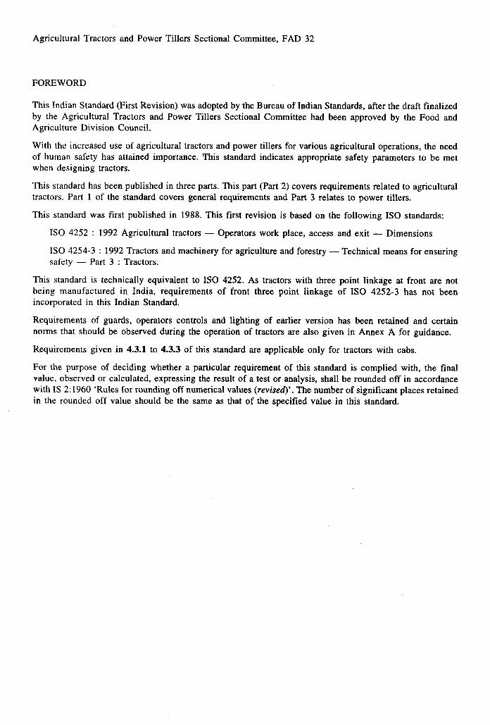
Agricultural Tractors and Power Tillers Sectional Committee, FAD 32
FOREWORD
This Indian Standard (First Revision) was adopted by-the Bureau of Indian Standards, after the draft finalized
by the Agricultural Tractors and Power Tillers Sectional Committee had been approved by the Food and
Agriculture Division Council.
With the increased use of agricultural tractors and power tillers for various agricultural operations, the need
of human safety has attained importance. This standard indicates appropriate safety parameters to be met
when designing tractors.
This standard has been published in three parts. This part (Par~2) covers requirements related to agricultural
tractors. Part 1 of the standard covers general requirements and Part 3 relates to power tillers.
This standard was first published in 1988. This first revision is based on the following IS0 standards:
IS0 4252 : 1992 Agricultural tractors - Operators work place, access and exit - Dimensions
IS0 4254-3 : 1992 Tractors and machinery for agriculture and forestry - Technical means for ensuring
safety - Part 3 : Tractors.
This standard is technically equivalent to IS0 4252. As tractors with three point linkage at front are not
being manufactured in India, requirements of front three point linkage of IS0 4252-3 has not been
incorporated in this Indian Standard.
Requirements of guards, operators controls and lighting of earlier version has been retained and certain
norms that should be observed during the operation of tractors are also given in Annex A for guidance.
Requirements given in 4.3.1 to 4.3.3 of this standard are applicable only for tractors with cabs.
For the purpose of deciding whether a particular requirement of this standard is complied with, the final
value, observed or calculated, expressing the result of a test or analysis, shall be rounded off in accordance
with IS 2: 1960 ‘Rules for rounding off numerical values (revised)‘. The number of significant places retained
in the rounded off value should be the same as that of the specified value in this standard.
Indian Standard zyxwvutsrqponmlkjihgfedcbaZYXWVUTSRQPONMLKJIHGFEDCBA
TRACTORS AN-DMACHINERYFOR
AND FORESTRY -TECHNICAL
ENSURING SAFETY zyxwvutsrqponmlkjihgfedcbaZYXWVUTSRQPONMLKJIHGFEDCBA
PART 2 TRACTORS
( First Revision ) zyxwvutsrqponmlkjihgfedcbaZYXWVUTSRQPONMLKJIHGFEDCBA
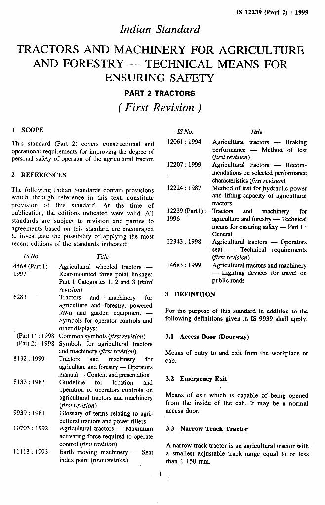
1 SCOPE
This standard (Part 2) covers constructional and
operational requirements for improving the degree of
personal safety of operator of the agricultural tractor.
2 REFERENCES
The following Indian Standards contain provisions
which through reference in this text, constitute
provision of this standard. At the time of
publication, the editions indicated were valid. All
standards are subject to revision and parties to
agreements based on this standard are encouraged
to investigate the possibility of applying the most
recent editions of the standards indicated:
IS zyxwvutsrqponmlkjihgfedcbaZYXWVUTSRQPONMLKJIHGFEDCBANo.
4468 (Part 1) :
1997
6283
(Part 1): 1998
(Part 2) : 1998
8132 : 1999
8133 : 1983
9939 : 1981
10703: 1992
11113: 1993
Title
Agricultural wheeled tractors -
Rear-mounted three point linkage:
Part 1 Categories 1, 2 and 3 (third
revision)
Tractors and machinery for
agriculture and forestry, powered
lawn and garden equipment -
Symbols for operator controls and
other displays:
Common symbols (first revision)
Symbols for agricultural tractors
and machinery yirst revision)
Tractors and machinery for
agriculture and forestry - Operators
-manual - Content and presentation
~Guideline for location and
operation of operators controls on
agricultural tractors and machinery
(first revision)
Glossary of terms relating to agri-
cultural tractors and power tillers
Agricultural tractors - Maximum
activating force required to operate
control (first revision)
Earth moving machinery - Seat
index point (first revision) zyxwvutsrqponmlkjihgfedcbaZYXWVUTSRQPONMLKJIHGFEDCBA
IS No.
12061 : 1994
12207 : 1999
12224: 1987
12239 (Partl)
1996
12343 : 1998
14683 : 1999
IS 12239 (Part 2) : 1999
AGRICULTURE
MEANS FOR
Title
Agricultural tractors - Braking
performance - Method of test
(first revision)
Agricultural tractors - Recom-
mendations on selected performance
characteristics (first revision)
Method of test for hydraulic power
and lifting capacity of agricultural
tractors
Tractors and machinery for
agriculture and forestry - Technical
means for ensuring safety - Part 1 :
General
Agricultural tractors - Operators
seat - Technical requirements
first revision)
Agricultural tractors and machinery
- Lighting devices for travel on.
public roads
3 DEFINITION
For the purpose of this standard in addition to the
following definitions given in IS 9939 shall apply.
3.1 Access Door (Doorway)
Means of entry to and exit from the workplace or
cab.
3.2 Emergency Exit
Means of exit which is capable of being opened
from the inside of the cab. It may be a normal
access door.
3.3 Narrow Track Tractor
A narrow track tractor is an agricultural tractor with
a smallest adjustable track range equal to or less
than 1 150 mm.

IS 12239 (Part 2) : 1999
4 REQUIREMENTS
4.1 Three-Point Linkages
The hazards of coupling implements with three
point linkages can be reduced by the use of
semi-automatic implement couplers (quick coupling
devices).
4.1.1 zyxwvutsrqponmlkjihgfedcbaZYXWVUTSRQPONMLKJIHGFEDCBAThree-Point Linkage at Rear
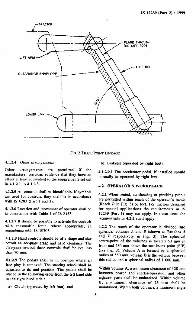
4.1.1.1 Forward of a plane passing through the
median plane of the pivot points of the lifting rods
in a three point coupling system, a minimum safety
margin of 25 mm shall be maintained between the
moving parts at each point of the lifting device’s
travel. This does not however apply for the extreme
upper and lower range of travel 0.1 n which are
defined in (a) below and illustrated in Fig. 1. A
minimum clearance of 25 mm or a minimum angle
of 3O*C shall be maintained between parts in shear
where the angle can change (see Fig. 2).
4
b)
For the total movement range, n, the lower
position A of the lower hitch point is limited
by the dimension in definition 3.3.14 and [14]
in Fig. 2 of IS 4468 (Part 1) while the upper
position E is limited by the maximum
hydraulic travel. Travel n’ corresponds to
travel n reduced upwards and downwards by
0.1 n and constitutes the vertical distance
between A’ and B’.
Within the distance of travel, a minimum
safety margin of 25 mm in relation to the
adjacent parts shall be maintained around the
profile of the lifting rods. /
4.1.2 Controls
4.1.2.1 Main controls
The main controls and their linkage shall be
arranged or protected in such a way that the
operator cannot reach them if he is standing on the
ground between the tractor and the mounted
implement.
4.1.2.2 External controls
When additional external controls are fitted, they
shall be arranged in such way that the operator can
actuate them from a safe position, for instance
where the three point hydraulic lift controls or the
additional controls for the lifting mechanism are
located outside the vertical planes formed by the
internal walls of the mudguards.
In addition, the three point hydraulic lifting
mechanism shall be actuated by means of controls
which either restridt the amount of movement to a
maximum of 100 mm each time the control is
actuated, the measurement points in this case are
formed by the coupling points on the lower arms of
the three point coupling; or operate on the operator
presence and continual activation principle (dead
man’s control).
4X2.3 Main controls on narrow-track tractors
The controls on narrow track tractors are arranged
in front of the transverse vertical plane through the
seat index point (SIP) as defined in IS 1 It 13. zyxwvutsrqponmlkjihgfedcbaZYXWVUTSRQPONMLKJIHGFEDCBA
FIG. 1 L~rn RANGE
2
IS 12239 (Part 2) : 1999
PLANE zyxwvutsrqponmlkjihgfedcbaZYXWVUTSRQPONMLKJIHGFEDCBATHROUGH
THE LIFT F!OOS
CLEARANCE ENVELO
__ -- -I
FIG. 2 THREE-POINT LINKAGE zyxwvutsrqponmlkjihgfedcbaZYXWVUTSRQPONMLKJIHGFEDCBA
4.1.2.4 Other arrangements
Other arrangements are permitted if the
manufacturer provides evidence that they have an
effect at least equivalent to the requirements set out
in 4.1.2.1 to 4.1.2.3.
4.1.2.5 All controls shall be identifiable. If symbols
are used for controls, they shall be in accordance
with IS 6283 (Part 1 and 2).
4.1.2.6 Location and movement af operator shall be
in accordance with Table 1 of IS 8133.
4.1.2.7 It should be possible to activate the controls
with reasonable force, where appropriate, in
accordance with IS 10703.
4.1.2.8 Hand controls should be of a shape and size
permit an adequate grasp and hand clearance. The
clealance around these controls shall be not less
than 70 mm.
4.1.2.9 The pedals shall be in position where all
free play is removed. The steering wheel shall be
adjusted to its mid position. The pedals shall be
placed in the following order from the left hand side
to the right hand side :
a) Clutch (operated by left foot), and
b) Brake(s) (operated by right foot).
4.1.2.9.1 The accelerator pedal, if installed should
normally be operated by right foot.
4.2 OPERATOR’S WORKPLACE
4.2.1 When seated, no shearing or pinching points
are permitted within reach of the operator’s hands
(Reach B in Fig. 3) or ~feet. For tractors designed
for special applications the requirements in IS
12239 (Part 1) may not apply. In these cases the
requirements in 4.2.2 shall apply.
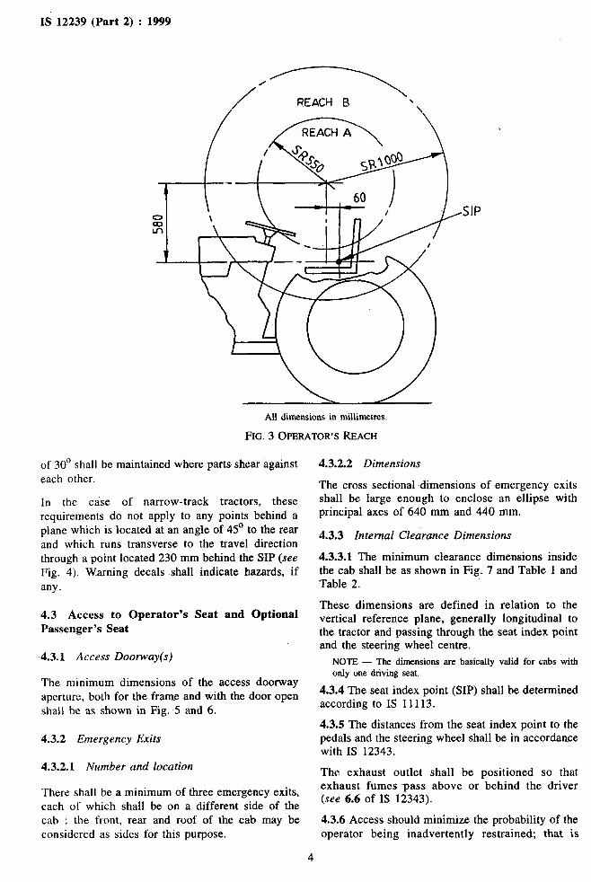
4.2.2 The reach of the operator is divided into
spherical volumes zyxwvutsrqponmlkjihgfedcbaZYXWVUTSRQPONMLKJIHGFEDCBAA and B (shown as Reaches A
and B respectively in Fig. 3). The spherical
centre-point of the volumes is located 60 mm in
front and 580 mm above the seat index point (SIP)
(see Fig. 3). Volume A is formed by a spherical
radius of 550 mm, volume B is the volume between
this radius and a spherical radius of 1 000 mm.
Within volume A, a minimum clearance of 120 mm
between power and inertia-operated, and other
adjacent parts shall be maintained. Within volume
B, a minimum clearance of 25 mm shall be
maintained. Within both volumes, a minimum angle
3
. . ’
$’
IS 12239 (Part 2) : 1999 zyxwvutsrqponmlkjihgfedcbaZYXWVUTSRQPONMLKJIHGFEDCBA
REACH 6 \ / 1.
All dimensions in millimetres.
FIG. 3 OPERATOR’S zyxwvutsrqponmlkjihgfedcbaZYXWVUTSRQPONMLKJIHGFEDCBAREACH
of 30’ shall be maintained where parts shear against
each other.
In the case of narrow-track tractors, these
requirements do not apply to any points behind a
plane which is located at an angle of 45’ to the rear
and which runs transverse to the travel direction
through a point located 230 mm behind the SIP (see
Fig. 4). Warning decals shall indicate hazards, if
any.
4.3 Access to Operator’s Seat and Optional
Passenger’s Seat
4.3.1 zyxwvutsrqponmlkjihgfedcbaZYXWVUTSRQPONMLKJIHGFEDCBAAccess Doorway(s)
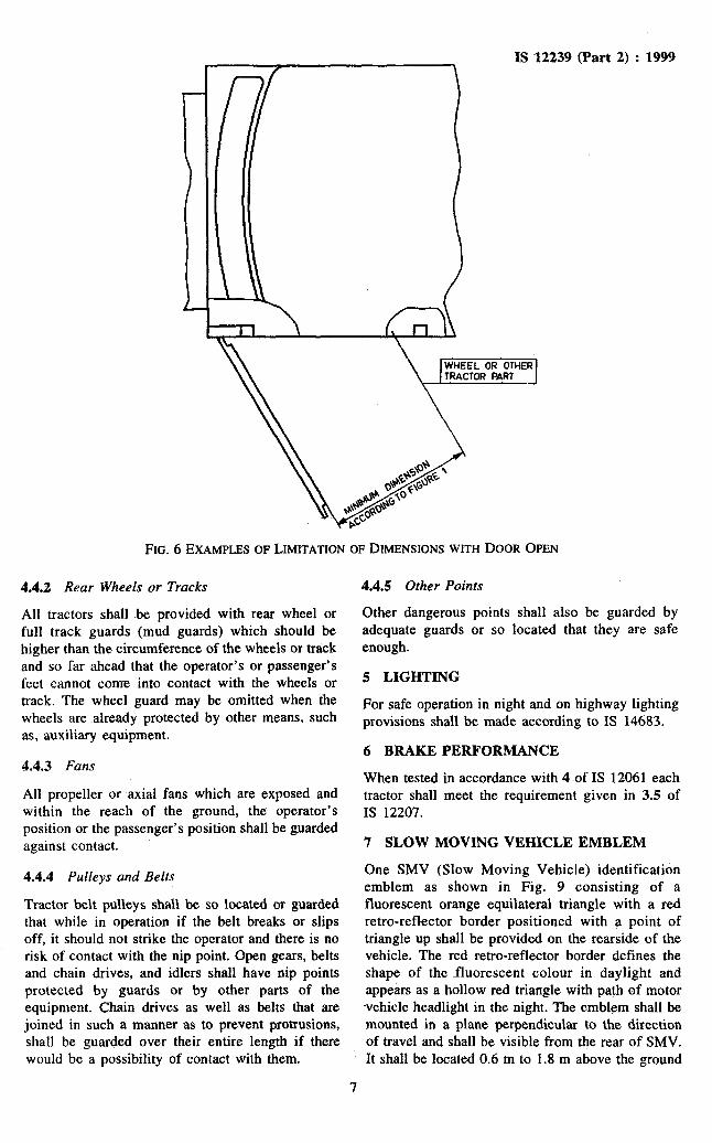
The minimum dimensions of the access doorway
aperture, both for the frame and with the door open
shall be as shown in Fig. 5 and 6.
4.3.2 Emergency Exits
4.3.2.1 Number and location
There shall be a minimum of three emergency exits,
each of which shall be on a different side of the
cab : the front, rear and roof of the cab may be
considered as sides for this purpose.
4.3.2.2 Dimensions
The cross sectional dimensions of emergency exits
shall be large enough to enclose an ellipse with
principal axes of 640 mm and 440 mm.
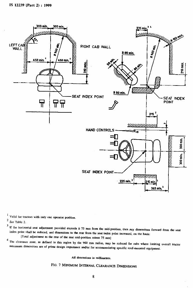
4.3.3 Internal Clearance Dimensions
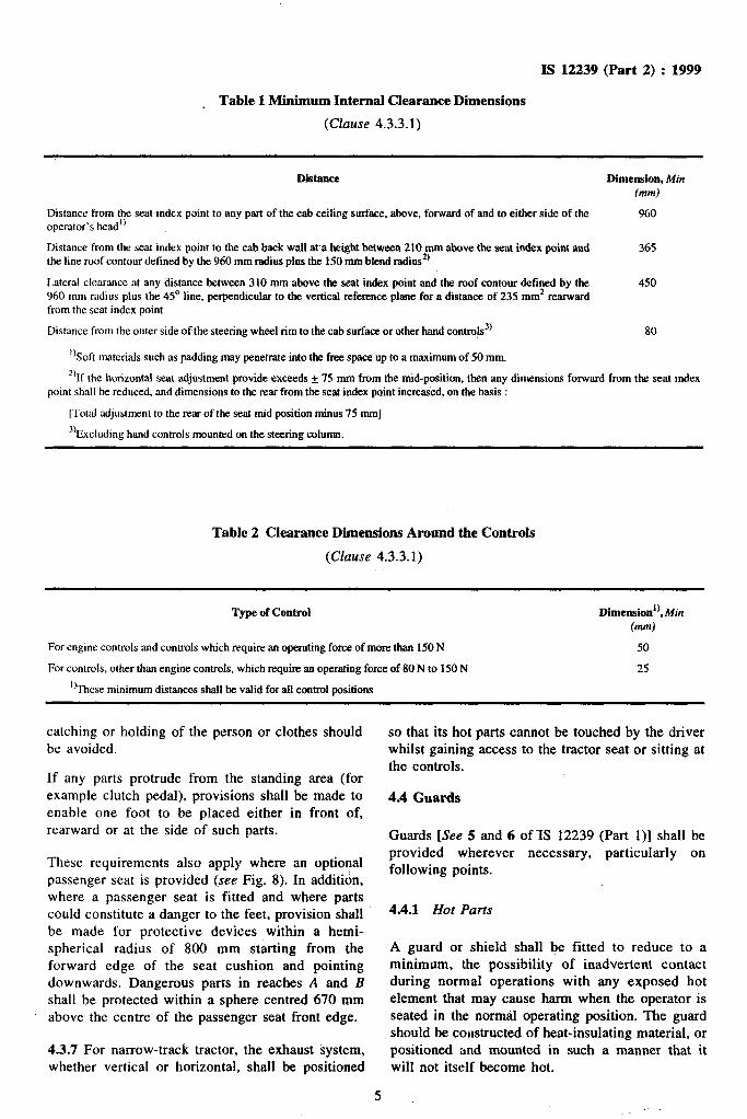
4.3.3.1 The minimum clearance dimensions inside
the cab shall be as shown in Fig. 7 and Table 1 and
Table 2.
These dimensions are defined in relation to the
vertical reference plane; generally longitudinal to
the tractor and passing through the seat index point
and the steering wheel centre.
NOTE - The dimensions are basically valid for cabs with
only one driving seat.
4.3.4 The seat index point (SIP) shall be determined
according to IS 11113.
4.3.5 The distances from the seat index point to the
pedals and the steering wheel shall be in accordance
with IS 12343.
The exhaust outlet shall be positioned so that
exhaust fumes pass above or behind the driver
(see 6.6 of IS 12343). -..
4.3.6 Access should minimize the probability of the
operator being inadvertently restrained; that is
4
IS 12239 (Part 2) : 1999
Table 1 Minimum Internal Clearance Dimensions .
(Clause 4.3.3.1)
Diitance zyxwvutsrqponmlkjihgfedcbaZYXWVUTSRQPONMLKJIHGFEDCBA
Distance from the seat index point to any part of the cab ceiling surface, above, forward of and to either side of the
operator’s head”
Distance from the seat index point to the cab back wall ata height between 210 mm above the seat index point and
the line roof contour defined by the 960 mm radius plus the 150 mm blend radius*)
Lateral clearance at any distance between 310 mm above the seat index point and the roof contour defined by-the
960 mm radius plus the 45’ line, perpendicular to the vertical reference plane for a distance of 235 mm* rearward
from the seat index point
Distance from the outer side of the steering wheel rim to the cab surface or other hand contro!s3’
‘)Soft materials such as padding may penetrate into the free space up to a maximum of 50 mm.
Dimedon, Min
tmm) zyxwvutsrqponmlkjihgfedcbaZYXWVUTSRQPONMLKJIHGFEDCBA
960
365
450
80
2’If the horizontal seat adjustment provide exceeds + 75 mm from the mid-position, then any dimensions forward from the seat index
point shall be reduced, and dimensions to the rear from the seat index point increased, on the basis :
[Total adjustment to the rear of the seat mid position minus 75 mm]
%xcluding hand controls mounted on the steering column.
Table 2 Clearance Dimensions Around the Controls
(Clause 4.3.3.1)
Type of zyxwvutsrqponmlkjihgfedcbaZYXWVUTSRQPONMLKJIHGFEDCBAControl Dimension’) Min , Wd
For engine controls and controls which require an operating force of more than 150 N
For controls, other than engine controls, which require an operating force of 80 N to 150 N
“These minimum distances shall be valid for ail control positions
50
-25
catching or holding of the person or clothes should
be avoided.
If any parts protrude from the standing area (for
example clutch pedal), provisions shall be .made to
enable one foot to be placed either in front of,
rearward or at the side of such parts.
These requirements also apply where an optional
passenger seat is provided (see Fig. 8). In addition,
where a passenger seat is fitted and where parts
could constitute a danger to the feet, provision shall
be made for protective devices within a hemi-
spherical radius of 800 mm starting from the
forward edge of the seat cushion and pointing
downwards. Dangerous parts in reaches zyxwvutsrqponmlkjihgfedcbaZYXWVUTSRQPONMLKJIHGFEDCBAA and B
shall be protected within a sphere centred 670 mm
above the centre of the passenger seat front edge.
4.3.7 For narrow-track tractor, the exhaust system,
whether vertical or horizontal, shall be positioned
so that its hot parts cannot be touched by the driver
whilst gaining access to the tractor seat or sitting at
the controls.
4.4 Guards
Guards [See 5 and 6 of-IS 12239 (Part l)] shall be
provided wherever necessary, particularly on
following points.
4.4.1 Hot Parts
A guard or shield shall be fitted to reduce to a
minimum, the possibility of inadvertent contact
during normal operations with any exposed hot
element that may cause harm when the operator is
-seated in the normal operating position. The guard
should be coustructed of heat-insulating material, or
positioned and mounted in such a manner that it
will not itself become hot.
5

IS 12239 (Part 2) : 1999
All zyxwvutsrqponmlkjihgfedcbaZYXWVUTSRQPONMLKJIHGFEDCBAdimensions in millimetres.
FIG. 4 LIMITATION TO OPERATOR’S MACH VOLUMES FOR NARROW-TRACK TR ACTORS
~~-~~--~~-~--~~~~~~~_~~_~_,
; \ \\ \ \ \ \ \
e_c-----_ -a \
*- I
\ .
. .
\ \
\ \ \ \ \ I I
I I
: zyxwvutsrqponmlkjihgfedcbaZYXWVUTSRQPONMLKJIHGFEDCBA
-L-J zyxwvutsrqponmlkjihgfedcbaZYXWVUTSRQPONMLKJIHGFEDCBA250 zyxwvutsrqponmlkjihgfedcbaZYXWVUTSRQPONMLKJIHGFEDCBAmin.
All dimensions in millimetres.
NOTE--For tractors where the seat can be reached straight from the footstep, the height at which the widths are me?sured may be decreased.
FIG. 5 ACCESS DOORWAY DIMENSIONS
6
IS 12239 (Part 2) : 1999 zyxwvutsrqponmlkjihgfedcbaZYXWVUTSRQPONMLKJIHGFEDCBA
WHEEL OR OTHER TRACTOR PART zyxwvutsrqponmlkjihgfedcbaZYXWVUTSRQPONMLKJIHGFEDCBA
FIG. 6 EXAMPLES OF LIMITATION OF DIMENSIONS WITH DOOR OPEN
4.4.2 zyxwvutsrqponmlkjihgfedcbaZYXWVUTSRQPONMLKJIHGFEDCBARear Wheels or Tracks
~A11 tractors shall Abe provided with rear wheel or
full track guards (mud guards) which should be
higher than the circumference of the wheels or track
and so far ahead that the operator’s or passenger’s
feet cannot come into contact with the wheels or
track. The wheel guard may be omitted when the
wheels are already protected by other means, such
as, auxiliary equipment.
4.4.3 Fans
All propeller or axial fans which are exposed and
within the reach of the ground, the operator’s
position or the passenger’s position shall be guarded
against contact.
4.4.4 Pulleys and Belts
Tractor belt pulleys shall be so located OT guarded
that while in operation if the belt breaks or slips
off, it should not strike the operator and there is no
risk of contact with the nip point. Open gears, belts
and chain drives, and idlers shall have nip points
protected by guards or by other parts of the
equipment. Chain drives as well as belts that are
joined in such a manner as to prevent protrusions,
shall be guarded over their entire length if there
would be a possibility of contact with them.
4.4.5 Other Points
Other dangerous points shall also be guarded by
adequate guards or so located that they are safe
enough.
5 LIGHTING
For safe operation in night and on highway lighting
provisions shall be made according to IS 14683.
6 BRAKE PERFORMANCE
When tested in accordance with 4 ~of IS 12061 each
tractor shall meet the requirement given in 3.5 of
IS 12207.
7 SLOW MOVING VEHICLE EMBLEM
One SMV (Slow Moving Vehicle) identification
emblem as shown in Fig. 9 consisting of a
fluorescent orange equilateral triangle with a red
retro-reflector border positioned with a point of
triangle up shall be provided on the rearside of the
vehicle. The red retro-reflector border defines the
shape of the fluorescent colour in daylight and
appears as a hollow red triangle with path of motor
vehicle headlight in the night. The emblem shall be
mounted in a plane perpendicular to the direction
of travel and shall be visible from the rear of SMV.
It shall be located 0.6 m to 1.8 m above the ground
7
*I__.-.-~..-..
IS 12239 IPart 2) : 1999
CA8 zyxwvutsrqponmlkjihgfedcbaZYXWVUTSRQPONMLKJIHGFEDCBAWAIL
I - SEAT INOEX POINT
IdAND CoNTROLS -*
SEAT INDEX POINT / I zyxwvutsrqponmlkjihgfedcbaZYXWVUTSRQPONMLKJIHGFEDCBA
365 zyxwvutsrqponmlkjihgfedcbaZYXWVUTSRQPONMLKJIHGFEDCBAmin.'. _
I
2 Valid for tractors with only one operator position.
See Table 2.
3 If the horizontal seat adjustment provided exceeds f 75 mm from the mid-position, thenany dimensions forward from the seat
index point shall be reduced, and dimensions to the rear from the seat index point increased, on the basis:
4 [Total adjustment to the rear of the seat mid-position minus 75 mm]
The clearance zone, as defined in this region by the 960 mm radius, may be reduced zyxwvutsrqponmlkjihgfedcbaZYXWVUTSRQPONMLKJIHGFEDCBAfor cabs where limiting overall tractor
maximum dimensions are of prime design importance and/or for accommodating specific roof-mounted equipment.
All dimensions in millimetres.
FIG. 7 MINIMUM INTERNAL CLEARANCE DIMENSIONS
8
L- SEAT INDEX POINT
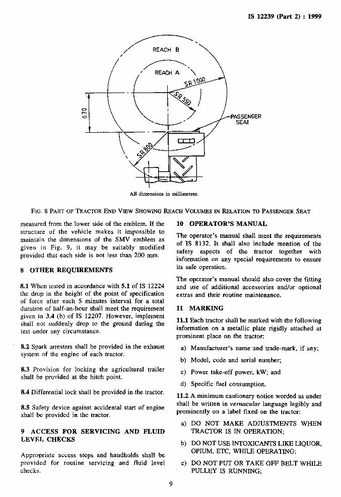
IS 12239 (Part 2) : 1999 zyxwvutsrqponmlkjihgfedcbaZYXWVUTSRQPONMLKJIHGFEDCBA
All dimensions in millimetres.
FIG. 8 PART OF TRACTOR END VIEW SHOWING REACH VOLUMES IN RELATION TO PASSENGER SEAT
measured from the lower side of the emblem. If the
structure of the vehicle makes it impossible to
maintain the dimensions of the SMV emblem as
given in Fig. 9, it may be suitably modified
provided that each side is not less than 200 mm.
8 OTHER REQUIREMENTS
8.1 When tested in accordance with 5.1 of IS 12224
the drop in the height of the point of specification
of force after each 5 minutes interval for a total
duration of half-an-hour shall meet the requirement
given in 3.4 (b) of IS 12207. However, implement
shall not suddenly drop to the ground during the
test under any circumstance.
8.2 Spark arresters shall be provided in the exhaust
system of the engine of each tractor.
8.3 Provision for locking the agricultural trailer
shall be provided at the hitch point.
8.4 Differential lock shall be provided in the tractor.
8.5 Safety device against accidental
shall be provided in the tractor.
9 ACCESS FOR SERVICING
LEVEL CHECKS
start of engine
AND FLUID
Appropriate access steps and handholds shall be
provided for routine servicing and fluid level
checks.
10 OPERATOR’S MANUAL
The operator’s manual shall meet the requirements
of IS 8132. It shall also include mention of the
safety aspects of the tractor together with
information on any special requirements to ensure
its safe operation.
The operator’s manual should also cover the fitting
and use of additional accessories and/or optional
extras and their routine maintenance.
11 MARKING
11.1 Each tractor shall~be marked with the following
information on a metallic plate rigidly attached at
prominent place on the tractor:
a> Manufacturer’s name ,and trade-mark, if any;
b) Model, code and serial number;
c> Power take-off power, kW; and
4 Specific fuel consumption.
11.2 A minimum cautionary notice worded as under
shall be written in zyxwvutsrqponmlkjihgfedcbaZYXWVUTSRQPONMLKJIHGFEDCBAvernacular language legibly and
prominently on a label fixed on the tractor:
a)
b)
c)
DO NOT MAKE ADJUSTMENTS WHEN
TRACTOR IS IN OPERATION;
DO NOT USE INTOXICANTS LIKE LIQUOR,
OPIUM, ~ETC, WHILE OPERATING;
DO NOT PUT OR TAKE OFF BELT WHILE
PULLEY IS RUNNING;
9

IS 12239 (Part 2) : 1999
4
e) zyxwvutsrqponmlkjihgfedcbaZYXWVUTSRQPONMLKJIHGFEDCBA
RED RETRD REFLECTIVE
A BORDER 3 STRIPS
FLUORESCENT ORANGE
EQUILATERAL TRIANGLE
Q) +I rl)
s
t--
NOTE - Emblem must be mounted with the point upward.
FIG. 9 SLOW-MOVING VEHICLE IDENTIFXZATION EMBLEM
DO NOT SIT OR STAND OR SIT IN AN
UNSAFE PLACE SUCH AS ROOF,
DRAWBAR, MUDGUARD, RUNNING
BOARD OR LOAD WHEN THE TRACTOR IS
MOVING;
NO PERSON SHOULD MOUNT OR
DISMOUNT FROM A TRACTOR WHILE IT IS
IN MOTION EXCEPT IN AN EMERGENCY;
THE OPERATORS OF TRACTOR SHOULD:
1)
2)
3)
4
5)
6)
BE ADEQUATELY TR%INEDANDwHEN
REQUIRED, PROPERLY LICENSED,
OBTAIN AND READ THE OPERATING
MANUAL BEFORE USING A TRACTOR
FOR THE FIRST TIME;
WEAR ADEQUATE AND WELL-
FITTING FOOTWEAR;
WEAR SNUG-FITTING CLOTHING;
KEEP HANDS, FEET AND CLOTHING
AWAY FROM ALL MOVING PARTS;
PUT THE GEAR SELECTOR, POWER
OPERATED ATTACHMENTS AND
7)
8)
POWER TAKE-OFF TO NEUTRAL AND
LOWER THE ATTACHED EQUIPMENT
TO THE GROUND BEFORE LEAVING
THE STOPPED TRACTOR;
LOCK THE BRAKE PEDALS
TOGETHER WHEN TRAVELLING ON
PUBLIC ROADS; AND
STOP AT ALL UNGUARDED RAILWAY
CROSSINGS AND MAKE SURE THAT
NO TRAINS ARE COMING.
11.3 BIS Certification Marking
Each tractor may also be marked with Standard
Mark for safety.
11.3.1 The use of the Standard Mark is governed
by the provisions of Bureau zyxwvutsrqponmlkjihgfedcbaZYXWVUTSRQPONMLKJIHGFEDCBAof Indian zyxwvutsrqponmlkjihgfedcbaZYXWVUTSRQPONMLKJIHGFEDCBAStandards
Act, 1986 and the Rules and Regulations made
thereunder. The details of conditions under which
the licence for the use of Standard Mark may be
granted to manufacturers or producers may be
obtained from the Bureau of Indian Standards.
10

IS zyxwvutsrqponmlkjihgfedcbaZYXWVUTSRQPONMLKJIHGFEDCBA12239 (Part 2) : 1999
ANNEX A
( Foreword )
INFORMATION ON SAFE OPERATION OF TRACTORS
A-l GENERAL
A-l.1 Operator
All operators of tractors should:
a>
b)
c)
4
e)
f,
be in good health, sound mind and be not
under the influence of any sort of intoxicants;
be adequately trained and, when required,
properly licensed;
obtain and read the operating manual before
using a tractor for the first time;
wear adequate and well-fitting footwear;
wear snug-fitting clothing; and
keep hands, feet and clothing away from all
moving parts.
A-l.2 Starting of Tractor
Before starting a tractor, the operator should:
4
b)
cl
4
e>
clear all material from the operator’s work
place and mud from the pedals;
inspect the tractor to make certain that it is
properly adjusted and is in good working
condition;
lubricate working parts, tighten all loose parts
and secure safety shields in place;
check engine oil level and water in radiator (in
case of water cooled engines); and
place all the controls in neutral.
A-l.3 Operating Conditions
4
b)
c)
4
e)
Tractors should not be started or operated in
buildings unless conditions are such that there
is no risk of fue or contamination of the air.
All shields for power take-offs, including the
tractor master shield and the power take-off
shaft shield, should be in place during use.
When power take-off isnot in use, the stub
shaft should be provided with a shield.
Except in an emergency, no person shoukd
mount or dismount from a tractor while it is
in motion.
All clutches should be engaged gradually,
particularly when starting to move heavy loads.
A-2 TRAVELLING
Aa2.1 General
A-2.1.1 When a safety frame or cab is provided, the
operator should use a seat belt. It is strongly
recommended that no seat belt be used if a safety
frame or cab is not provided.
A-2.1.2 Adjustable wheels should, whenever
necessary, be spread as far as practicable,
considering the work to be done, to reduce tipping
hazards.
A-2.1.3 Tractors should not be driven faster than is
safe, having regard to prevailing conditions.
A-2.1.4 While a tractor is moving, no person
should:
stand or sit in an unsafe place such as roof,
drawbar, mudguard, running board or load;
climb from one tractor or trailer to another;
jump on or off except in emergencies;
apply wheel chokes; and
leave arms, legs or any object protruding
outside.
A-2.1.5 The operator should check brake adjustment
at the start of the day, before starting down steep
slopes and before entering a public highway.
A-2.1.6 Tractors should be driven with particular
care:
a) over sloping, uneven, soft, slippery or
otherwise unsafe ground;
b) along side ditches or banks;
c) when turning;
d) when reversing; and
e) when driven with any attachment that
drastically raises or changes the tractor’s
centre of gravity.
A-2.1.7 Owing to the possibility of tipping
backward, particular care should be taken in driving
when:
a) transporting heavy loads up a slope;
b) using rear wheel weights or ballast in rear
tyres;
11

IS 12239 (Part 2) : 1999
c) using rear-mounted equipment;
d) raising the position of the hitch point on towed
loads;
e) the rear wheels dig into soft ground;
f) using forward gear if the wheels are frozen to
the ground; and
g) attempting to drive forward if the rear wheels
are in a ditch or hole.
A-2.1.8 If necessary to prevent rearing, the front of
the tractor should be weighted.
A-2.2 Travelling on Public Roads
A-2.2.1 When travelling on public roads, the
operator should:
a)
b)
c>
4
e)
8)
h)
3
lock the brake pedals together;
comply with all traffic laws and regulations;
stop at all unguarded railway crossings and
make sure that no trains are coming;
signal intention to turn, slow down or stop;
keep on the correct side of the road and, when
it is safe to do so, pull of the highway to allow
faster traffic to pass;
shift to a lower gear for control when going
downhill;
shift to a lower gear to avoid stalling when
going uphill; and
reduce speed when the roads are slippery.
A-2.2.2 The moving of tractors should be planned
in such a way that:
a) moves are made during daylight hours; and
b) moves are not made during periods of heavy
traffic.
A-2.2.3 When moves are made during the night or
other periods of reduced visibility, all lights and
reflectors should be used as required by law, and
they should be kept in go~od working condition and
clean.
A-2.2.4 Rear-view mirror should be properly
adjusted.
A-2.2.5 In case of travel during rain and hot sun
when a cab is not provided, provision should be
made to mount a canopy above the driver’s seat.
A-3 REVERSING AND TURNING
A-3.1 Speed should be reduced, using the tractor
throttle as much as possible, before maiking any turns.
A-3.2 Before turning or reversing, the tractor
operator should make it certain that there are no
workers or obstacles in the path of travel.
A-3.3 When a tractor is mired in mud or stuck in
a ditch, the operator should always attempt to drive
out in reverse gear only. If this attempt is
unsuccessful, he may secure logs or planks behind
the rear wheels, to increase traction, and again
attempt to drive out using reverse gear. Under no
condition should logs or planks be secured in front
of the rear wheels to increase traction.
A-4 STOPPING
A-4.1 Before leaving a stopped tractor, the operator
should:
a>
b)
c>
4
e)
~shift the gear selector to neutral;
re-engage the master clutch, except in the case
of torque converter machines;
lock the parking brake;
lower attached equipment to the ground; and
put all power-operated attachments and power
take-off into neutral.
A-4.2 The operator should not dismount unless the
tractor _is stationary and there is an adequate and
safe place for him to step onto.
A-4.3 When slowing down or stopping, brakes
should be applied equally to the two rear wheels.
A-4.4 Tractors should not haul heavy vehicles or
machinery unless they can be stopped in a safe and
controlled manner.
A-5 USE OF ATTACHED EQUIPMENT
A-5.1 Towed equipment should be attached only to
the drawbar provided on the tractor.
.--..._ ..” A-S.2 In no case should attachments be secured at
the front or rear axle, to the seat bracket or to any
other frame member.
A-5.3 When ~attachments are hitched to the tractor:
a>
b)
c>
the attachment should be blocked with blocks
or chokes, if the tractor is backed;
if the attachment is pulled onto the tractor, the
attachments, should be kept under control by
brakes or chokes; and
no person should remain between the tractor
and the attachment, and the drawbar should be
handled with a hook or other suitable device.
A-5.4 When attachment and tractor are unhitched,
both vehicles should be blocked by brakes or
chokes. 1 j
12

IS zyxwvutsrqponmlkjihgfedcbaZYXWVUTSRQPONMLKJIHGFEDCBA12239 (Part 2) : 1999
A-5.5 All shield should be secured in place after
hitching and before the use of any attachment.
A-6 CARRYING OF PASSENGERS OR OBJECTS
A-6.1 Tractors should not carry:
a) any person for whom there is not a safe seat,
b) children,. or
c) loose objects unless a safe place is provided
for them.
A-7 TOWING AND PUSHING
A-7.1_ A tractor should not be used to, push other
vehicles unless an adequate and securely fastened
push bar is fitted to it.
A-7.2 Tractors should not haul loads so heavy as to
prevent effective control, specially on any sloping,
uneven, soft or otherwise unsafe ground.
A-8 OPERATING ON SLOPING GROUND
A-8.1 When starting up a slope, the operator should
choose a power gear to avoid stalling or shifting of
gears on the slope and should engage the clutch
slowly to avoid upsetting backwards.
A-8.2 Adjustable wheels should be spread as far as
possible for the job at hand.
A-8.3 The gear lever should not be put in neutral
and clutch pedal should not be disengaged when
descending slopes. A low gear should be selected
to assist in braking the tractor.
A-8.4 If necessary to prevent rearing, the front of
the tractor should be weighted when ascending a
slope, or the tractor should preferably be backed up
to the top.
A-8.5 Unbraked towed equipment should not be
taken down steep slopes without extreme caution.
A-9 STATIONARY WORK
Ai9.1 When using the tractor as a source of power
for stationary power take-off or belt work,
a) all shields and guards should be in place before
the power is applied,
b) the tractor frame should be earthed to remove
static electricity, and
c) while threshing, spark arrestor should be used
on the exhaust pipe.
A-9.2 When tractors are used for stationary work
inside a building, adequate means of removing
exhaust gases and supplying fresh air should be
provided.
A-9.3 When a tractor with a winch is used for
pulling, the tractor should be properly aligned in the
direction of the pull.
A-10 TRACTOR FUELLING
A-10.1 When the fuel tanks of internal combustion
engines are being filled:
a) the engines should not be running, and
b) no open flame devices, open lights, lighted
cigarettes or the like should be allowed.
A-10.2 Hot engines should be allowed to cool down I ,
before refuelling. Normally, the fuel tank should be
refilled in the evening after the day’s work.
A-10.3 After fuelling, some time should be allowed
for fuel vapours to disappear before the engine is
re-started.
A-10.4 Contact should at all times be maintained
between the metal outlet of the refuelling hose or
the can spout, on the one hand, and the fuel tank
opening on the tractor on the other, or other means
of bonding should be ensured to minimize the
possibility of an explosion or outbreak of fire due
to the discharge of an accumulation of static
electricity.
A-10.5 The tractor fuel system should be checked
frequently to detect fuel leaks. To be checked in
particular are the fuel tank seams, fuel lines, fuel
filler caps, fuel line shut-off valves, chokes and all
fuel line connections.
A-10.6 Fire extinguishers should be provided on the
tractor, at the refuelling point and in the building
where the tractor is stored.
13

Bureau of Indian Standards
BlS is a statutory institution established under the Bureau of f&iart Stan&r& Act, 1986 to promote
harmonious developinent of the activities of standardization, marking and quality certification of goods zyxwvutsrqponmlkjihgfedcbaZYXWVUTSRQPONMLKJIHGFEDCBAand
attending to connected matters ix-the country.
Copyright
BIS has the copyright of all its publications. No part of these publications may be reproduced in any form
without the prior permission in writing of BIS. This does not preclude the free use, in the course of
implementing the standard, of necessary details, such as symbols and sizes, type or grade designations.
Enquiries relating to copyright be addressed to the Director (Publication), BIS.
Review bf Indian Standards
Amendments are issued to standards as the need arises on thhc basis of comments. Standards are also reviewed
periodically; a standard along with amendments is reaffirmed when such review indicates that no changes are
needed; if the review indicates that changes are needed, it is taken up for revision. Users of Indian Standards
should ascertain that they are inpossession of the latest amendments or edition by referring to the latest issue
of ‘BIS Handbook’ and ‘Standards Monthly Additions’
This lndian Standard has been developed from Dot: No. FAD 32 (837).
Amendments Issued Since Publication
Amend No. Date of Issue Text Affected
BUREAU OF INDIAN STANDARDS
Headquarters:
Manak Bhavan, 9 Bahadur Shah Zafar Marg, New Delhi 110002
Telephones: 323 0131,323 33 75,323 94 02
Regional Offices:
Central : Manak Bhavan, 9 Bahadur Shah Afar Marg
Eastern : l/14 C.I.T. Scheme VII M, V.I.P. Road, Maniktola
CALCUTTA 700054
Northern : SC0 335-336, Sector 34-A, CHANDIGARH 160022
Southern : C.I.T. Campus, IV Cross Road, C!IENNAI 600113
Western : Manakalaya, E9MIDC, Marol, Andheri (East)
MUMBAI 400093
Branches : AHMADABAD. BANGALORE. BHOPAL. BHUBANESHWAR.
COIMBATORE. FARIDABAD. GHAZIABAD. GUWAHATI.
HYDERABAD. JAIPUR. KANPUR. LUCKNOW. NAGPUR.
PATNA. PUNE. THIRUVANANTHAPURAM.
NEW DELHI 110002
Telegrams: Manaksanstha
(Common to all offices)
Telephone
323 76 17,323 38 41 WC, .“-
{ 337 337 84 86 99,337
26,337
85 9120 61
60 38 43
60 20 25
{ 2350216,2350442 235 15 23 15 i
19,235 :
{ 832 832 78 92 95,832 78 78 ‘58 92
91,832
; 1
i
F’rinted zyxwvutsrqponmlkjihgfedcbaZYXWVUTSRQPONMLKJIHGFEDCBAa t zyxwvutsrqponmlkjihgfedcbaZYXWVUTSRQPONMLKJIHGFEDCBASimco Printing Prew, Delhi, India