IS 11570 (1985): Criteria for hydraulic design of ... · IS : 11570 - 1985 Indian Standard CRITERIA...
34
Disclosure to Promote the Right To Information Whereas the Parliament of India has set out to provide a practical regime of right to information for citizens to secure access to information under the control of public authorities, in order to promote transparency and accountability in the working of every public authority, and whereas the attached publication of the Bureau of Indian Standards is of particular interest to the public, particularly disadvantaged communities and those engaged in the pursuit of education and knowledge, the attached public safety standard is made available to promote the timely dissemination of this information in an accurate manner to the public. इंटरनेट मानक “!ान $ एक न’ भारत का +नम-ण” Satyanarayan Gangaram Pitroda “Invent a New India Using Knowledge” “प0रा1 को छोड न’ 5 तरफ” Jawaharlal Nehru “Step Out From the Old to the New” “जान1 का अ+धकार, जी1 का अ+धकार” Mazdoor Kisan Shakti Sangathan “The Right to Information, The Right to Live” “!ान एक ऐसा खजाना > जो कभी च0राया नहB जा सकता ह ै” Bhartṛhari—Nītiśatakam “Knowledge is such a treasure which cannot be stolen” IS 11570 (1985): Criteria for hydraulic design of irrigation intake structures [WRD 14: Water Resources]
Transcript of IS 11570 (1985): Criteria for hydraulic design of ... · IS : 11570 - 1985 Indian Standard CRITERIA...

Disclosure to Promote the Right To Information
Whereas the Parliament of India has set out to provide a practical regime of right to information for citizens to secure access to information under the control of public authorities, in order to promote transparency and accountability in the working of every public authority, and whereas the attached publication of the Bureau of Indian Standards is of particular interest to the public, particularly disadvantaged communities and those engaged in the pursuit of education and knowledge, the attached public safety standard is made available to promote the timely dissemination of this information in an accurate manner to the public.
इंटरनेट मानक
“!ान $ एक न' भारत का +नम-ण”Satyanarayan Gangaram Pitroda
“Invent a New India Using Knowledge”
“प0रा1 को छोड न' 5 तरफ”Jawaharlal Nehru
“Step Out From the Old to the New”
“जान1 का अ+धकार, जी1 का अ+धकार”Mazdoor Kisan Shakti Sangathan
“The Right to Information, The Right to Live”
“!ान एक ऐसा खजाना > जो कभी च0राया नहB जा सकता है”Bhartṛhari—Nītiśatakam
“Knowledge is such a treasure which cannot be stolen”
“Invent a New India Using Knowledge”
है”ह”ह
IS 11570 (1985): Criteria for hydraulic design ofirrigation intake structures [WRD 14: Water Resources]


1S :11570-1985
Indian StandardCRITERIAFOR
HYDRAULIC DESIGN OF IRRIGATIONINTAKE STRUCTURES
In take St ructures Sect iona l Commit tee, BDC 55
Chairman RepresentingSHRI K. MADHAVAN Central Water Commission, New Delhi; and
Institution of Engineers, New Delhi
Membe mSHRI S. CHAKRABARTI Common India Limited, Bombay
SHRI S. R. MUNIPALLI ( Alternate )CHIEF ENGINEER-I ( IRRIGATION ) Inst itu te of Hydrau lics Hydrology, Poondi
AND DPLECTORASSISTANT DIRECTOR-I (HYDRAULICS ) ( Alternate )
CHIEF ENGINEER(THEIN DAM Irr iga t ion Works, Governmen t of Punjab,DESIGN) Chandiga rh
DIRECTOR (TRP) ( Alternate )SHRI J . D’CRUZ Delh i Water Supply Under taking, New Delh i
SHRXS. A. SWAMY ( Alternate )DIRECTOR (HCD)-I Cent ra l Water Commission , New Delh i .
“DEPUTY DIRECTOR ( PH-I ) ( Alternate)DIRECTOR Cent ra l Water and Power Research Station,
PuneSHRI V. K. KULKARNI ( Alternate )
MANAGING DIRECTOR Tamil Nadu Public Works Engineer ingCorpora t ion Ltd, Madras
SHRI MOHENDJ R SINGH Ir r iga t ion Depar tment , Governmen t of Ut ta rPradesh , Lucknow
DR A. V. NATARAJ AN Cent ra l In land Fisher ies Resea rch Inst itu te,Bar raojoire
SHR1 A. B. MUKHERJ EE ( Alternate )SHRI”T. C. PAUL Ir r iga t ion and Power Research Inst itu te,
Amrit sarSHRI N. RAMASWAMY Irr iga t ion Depar tment , Governmen t of Guja ra t
GandhinagarSHRI B. J . SHAH ( Alternate )
( Continued on page 2 )
@ Copyright 1986INDIAN STANDARDS INSTITUTION
This publication is protected under the Indian CopyrightAct ( XIV of 1957 ) andreproduct ion in whole or in par t by any means except with wr it t en permission of thepublisher shall be deemed to be an In fr ingement of copyr igh t under the sa id Act .
—.”,,..>— —----- - — .--—. - - -’ 1’ ,’ ‘—
,\
,.
——.—..... .- . .--._.._._ -. -/.
,
-,
*
..

IS:1 1 5 7 0 -1 9 8 5
( Continuedfrom page 1 )
Members SECRETARY
J OINT SECRETARY (Alternate ) DR H. R. SHARMA SUPERINTENDING ENGINEER
SHRI N . VISVANATHAN
SHRI G. RAMAN, Director (Civ Engg)
Representing Cent r ;l$oard of Ir r iga t ion and Power , New
Cent ra l E lect r icity Author ity, New Delh i Ir r iga t ion Depar tment , Governmen t of Maha-
rash t ra . Nasik Nat iona l Hidroelect r ic Power Corpora t ion
Limited, New Delh i Director Genera l, 1% (&-officio Member)
Secretary SHRI P. SATYANARAYANA
Assistant Director (Civ Engg), IS1
2

IS : 1 1 5 7 0 - 1 9 8 5
Indian Standard CRITERIA FOR
HYDRAULIC DESIGN OF IRRIGATION INTAKE STRUCTURES
0. FOREWORD
0.1 This Indian Standard was adopted by the Indian Standards Institution on 6 December 1985, after the draft finalized by the Intake Structures Sectional Committee had been approved by the Civil Engineering Division Council.
0.2 An intake is provided in an irrigation development to allow water into a channel or tunnel under controlled conditions. The intake design shall be such as to:
a) give minimum hydraulic losses, b) provide smooth entry into the water conductor system, and c) prevent/minimize ice, floating trash and coarse sediment entering
the tunnel or channel. 0.3 For the purpose of deciding whether a particular requirement of this standard is complied with, the final value, observed or calculated, express- ing the result of a test or analysis, shall be rounded off in accordance with the IS : 2-1960”. The number of significant places retained in the rounded off value should be the same as that of the specified value in this standard.
1 . SCOPE
1 .1 This standard lays down the criteria for hydraulic design of irrigation intake structures. Typical layouts of intake structures are also covered in this standard.
2. TYPES AND CHOICE OF INTAKES
2.1 The position and location of an intake generally depend upon the type of in take and may be broadly classified as under:
a) Run-of the river type intakes, and b) Reservoir type intakes.
2.2 Run-of the River Type Intake
2.2.1 Run-of the river type intakes are those which draw water from the fresh continuous river inflows without any appreciable storage upstream of the diversion structure. A typical sketch of intake to meet
*Rules for rounding off numer ica l va lues ( r evised).
3

IS : 1 1 5 7 0 - 1 9 8 5
special characteristics, such as steep slopes, high peaks and short duration flood flows and high sediment loads, is shown in Fig. 1.
r .RIGHf BANK CANAL
RIGHT BANK HEAD WORKS
FT BANK HEAD WORKS
SLUICE FLOW
SLUICE GATE
CREST OF DIVERSION
GUIDE WALL
1 B Modified Design of Head Works FIG. 1 RUN-OF RIVER TYP E INTAKE
4
FLOW

I$ : 1 1 5 7 0 - 1985
2.2.1.1 Intakes adjacent to diversion w eir/barrage - In a run of the river type development without any diurnal pondage, an intake of irriga- tion water conductor system is placed upstream of diversion dam or barrage. A typical layout is shown inFig. 2.
FLUSHING CANAL
DESlLTlNG SLUICE
t X
IRRI%ATION CANAL
v. STILLING BASIN AND ENERGY DISSIPATION ARRANGEMENT
SECTION XX
FIG. 2 TYPICAL CANAL INTAKE
2.2.1.2 Drop type intake - A diversion structure, consisting of a trench weir and trashrack structure over it, is constructed across moun- tain streams to entrap the entire minimum discharges of the river. The trench may be either in the river bed or in the weir (raised above the river bed) as per typical layout shown in Fig. 3 and Fig. 4.
2.3 Reservoir Type Intake
2.3.1 Reservoir type intake is provided where discharges for irrigation are drawn from storage built up for this purpose. Depending on the head, this is further categorized as under:
a) Low head (up to 15 m),
b) Medium head (15 to 30 m), and
4 High head (above 30 m).
5


y-OPENING HANDLE FOR SINGLE FLUSHING GATE GATE GROOVE ATE CONTROL PLATFORM
N S L /--------
N S L ____--_------ -----------5.
FLUSHING CONDUIT -/
3B Sectional Elevation FIG. 3 DROP TYP E IRRIGATION INTAKE TRENCH IN RIVER BED

UIS RIVER BED
ENCH WEIR (TRASH RACK NOT SHOWNI
CURTAIN WALLS m . .
SLOPE 3:1 = 2
DIS RIVER 7 BED
% zi
GATE GROOVE FLUSHING SLUICE
EMBANKMENT
4A General FIG. 4 DROP TYP E IRRIGATION INTAKE ( TRENCH IN THE WEIR ) -:Contd

STOP LOG GATE A OPERATING PLAlrUKh(
/-BREAST WALI ’
HEAD REGULATOR GATE
CEMENT CONCRETE ~-CEMENT
LEAN 1:4:8 (300mm)
CONCRETE CONCRETE l:4% (300 mm)
4B L-Section Through Intake
TONE PITCHING
coNCRETE E . . CEMENT CONCRETE z
I 1:4:8 I 3 0
4C L-Section Through Flushing Duct I
FIG. 4 DROP TYPE IRRIGATION INTAKE ( TRENCH IN THE WEIR ) G
E

IS:11570- 1985
2.3.1.1 Intake in concrete or masonry dams - In the case of concrete or masonry dams irrigation intake structure can be located either at the toe when operating head is low or in the body of the dam itself when operating head is medium or high. Typical layouts are shown in Fig. 5A, 5B and 5C.
2.3.1.2 Intake in earthen dams - When the reservoir is formed by an earthern dam, the irrigation tunnel is laid below it or in the abutment. The intake structure for such situations will be a sloping intake or tower type of intake. Typical layouts for sloping and tower type intakes are shown in Fig. 6A, 6B and 6C respectively. As far as possible, reinforced cement concrete pressurized system should be avoided in the body of the earth dam. Measures like provision of steel liners and suitable drainage downstream of core, provisions of joints for differential settlements when not founded on rock should be considered in case pressure conduits are provided under earth dams.
‘lop: “ARIES FROM 1.5 :, - tn ,..
i) APPROACH GEOMETRY
5A Semicircular Type Intake Structure - Contd
10

IS : 1 1 5 7 0 - 1 9 8 5
BELL MOUTH
‘BOTTOM LINE
SEWCIRCULAR FROM RECT. TRASH RACK AR SECTION
ii) ELEVATION
PIERS
iii) PLAN
5A Semicircular Type Intake Structure
FIG. 5 RESERVOIR TYP E IRRIGATION INTAKE STRUCTURES IN
CONCRETE/MASONRY DAMS - Contd
11

AXIS OF $ OF GATE GALLERY
JET FLOW GATE
9 AIR VENT
+ I
;r) LGATE SLOT LCONDUlf APRON BELLMOUTH
5B Typical Installation in a Concrete/Masonry Dams - ContiJ
FIG. 5 RESERVOIR TYP E IRRIGATION INTAKE STRUCTURES IN
CONCRETE/MASONRY DAMS

EMERGENCY GATE
I - INTAKE 1 MASONRY WELL I DAM
AND SERVICE
AIR VENi PIPE
CONDUIT
TRASH RACK 0: MAXIMUM BETWEEN
D1 AND D2
INTAKE WALLA
5C Typical Installation in a koncrete/Masonry Dams FIG. 5 RESERVOIR TYP E IRRIGATION INTAKE STRUCTURES IN
CONCRETE/MASONRY DAMS

TRASH
‘i OF MAIN INTAKE SHAFT
r1RAS.H RACK
MAIN INTAKE FOR FINAL STAGE OPER
LOW LEVEL INTAKE FOR INITIAL STAGE OPERATION (MAIN INTAKE PLUGGED)
L SQUARE SECTION
TRANSITION I LOCATION OF
PLUG1
L MS CONDUIT CIRCULAR
T VALVE CHAMBER
Frc.6A TYPICAL INSTALLATION IN AN EARTH DAM - SLOPINGINTAKE

IS :11570 - 1985
RACK TRASH
. 0.8 01 I rTRA8H RACK
BELL MOUTH J
‘kTRAlGH1 LELBOW LENGJH
FIG. 6B TYPICAL INSTALLATION IN AN EARTH DAM
TOWER TYPE INTAKE ( TYPE I )
AIR VENT PIPE
TUNNE 1
‘WING WALL EARTH DAM -ST AUNC HIM6
. RING
I
/CONDUIT
WALL
r L INTAKE WALL
D = Maximum Between D. and &
FIG. 6 C TYPICAL INSTALLATION IN AN EARTH DAM
TOWER TYPE INTAKE ( TYPE II )
1 5

IS : 1 1 5 7 0 - 1 9 8 5
2 .3 .1 .3 Intake in reservoir independent of dam - In case of a high- head installation; irrigation tunnel taking off from a storage reservoir, the intake is located at a distance from the dam. The intake structure of such a layout will be either tower type semicircular, circular, rectangular or inclined.
3 . LAYOUT OF INTAKE STRUCTURE
3.1 Main components of an irrigation intake structure are listed below: a) Trashrack and supporting structures; b) Anti-vortex devices; c) Bell-mouth entrance with transition and rectangular to circular
opening; and d) Gate slot enclosures with air vents.
3.1.1 The efficient and economic design of an intake to serve the functions set out in 0.2 will depend upon the conditions prevailing in each development. In 5.3.3 and 5.3.5 few formulae have been suggested which may be modified to suit any special condition. Hydraulic model studies may be necessary under special conditions.
3.2 The main types of layouts are given below. 3.2.1 Canal Intake - In low-head deve!opment, the intake admits
water into diversion/irrigation canal. Sediment excluder or trap is an essential component of this type of intake. The invert at inlet is generally raised to form a sill to prevent the entry of coarse fraction of- bedload into the canal. A skimmer wall to prevent the floating material and trashrack to check entry of submerged heavy bodies, such as tree trunks, are provided at the entrance. Stilling basin and energy dissipation devices on the downstream of intake, as shown in Fig. 2, are also required. In the case of trench provided either in the river bed or in the weir, desilting basin is located in the canal and the sediment entrapped is removed either manually or by flushing sluices. In some situations desilting tunnels may also be provided upstream of intake (see IS : 6531-1972* and IS : 9761-19817).
3.2.2 Semicircular Type of Intake Structure - In this layout, the structure supporting the rack is formed in a semicircle in plan in front of the tunnel opening so that no parts of rack fall within a radius of 1’143 B froni face of opening, where B is the width of opening of tunnel. The main features of semicircular intake structure are:
a) Semicircular trashrack structure; b) Bell-mouth entrance to tunnel;
*Criteria for design of canal head regulators. tcriteria for hydraulic design of hydropower intakes.
16

IS : 1 1 5 7 0 - 1 9 8 5
c) Gate slot enclosures with air vent (Typical details are shown in Fig. 5A, 5B and 5C >; and
d) Transition from rectangular to circular conduit.
3.2.3 Sloping Intake - Sloping intake is provided in an earthen dam as shown in Fig. 6A. Trashrack for the intake (made by mild steel rectangular bars) is provided at the entrance. The top and sides at the entrance are provided with bell-mouth.
3.2.4 Vert ical Intake - Vertical intake is essentially a circular vertical shaft. The structure above it supporting the trashrack is either tower type or hemispherical cage. The main features of this layout are:
a> b) 4 4
Hemispherical or tower type rack supporting structure;
Circular bell-mouth to shaft;
Vertical intake shaft; and
Right-angled bend at the base of the shaft or an elbow to join the tunnel.
In case of tower type intake structure, flow is regulated either by a single cylinderical gate or by a number of gates in the tower or %y a separate gate in the gate shaft. In case of hemispherical intake structure, the control gate is provided in the tunnel portion only. A typical design of hemispherical vertical intake structure is shown in Fig. 6A.
4. CONDITIONS FOR LOCATION AND LAYOUT OF INTAKE STRUCTURE
4.1 Factors influencing the choice of location and layout of intake structure are:
a) Type ~of development that is run-of river scheme or storage reservoir_;
b) Location and type of dam/weir;
c) Type of water conveyance system that is tunnel or canal; and
d) Topographical features of area.
4.2 The conditions under which the various typical layouts of intake as classified in 3.2.1 to 3.2.4 are adopted, are given below.
4.2.1 Canal Intake - This type of layout is adopted when:
a) reservoir is of small capacity formed by a weir or barrage;
b) intake is to function under low heads; and
c) the topography and geology permit straight reaches suitable for such type of intake.
17

IS:11570-1985
42.2 Semicircular Type of Intake Structure
This type of layout is adopted when:
a) a reservoir is formed by a concrete or masonry dam and outlet tunnel is laid in the body of the dam;
b) the topography and geology permit to have almost vertical face at tunnel inlet portal; and
c) the minimum water depth above the centre line of intake is more than 0’8 of the entrance height.
42.3 Sloping Type of Intake Structure This type of layout is adopted when:
a) the reservoir is formed by an earthen dam and tunnel is laid below it; and
b) the intake is subjected to low-head variations like in run-of the river type.
42.4 Vert ical Type of Intake Structure This type of layout is adopted when: a) the intake is located at a distance from upstream face of the dam;
b) the reservoir is formed by an earthern dam and outlet tunnel is laid below it; and
c) the intake is subjected to large head variations, resulting in complete submergence of structure.
5. HYDRAULIC DESIGN OF COMPONENTS OF INTAKE
5.1 Centre Line of Intake
5.1.1 Centre line of intake shall be located well below the minimum draw down level to prevent formation of vortices. Suitable arrange- ments, such as cross walls, floating grid may be provided if necessary to prevent/minimize, vortices. Cover of water over the roof of the intake for the prevention of the formation of air entraining vortices both at vertical or horizontal pipe intake may be computed for the purpose of preliminary design from the set of curves given in Fig. 7 A and 7B by trial method ( see Appendix A >. For important works the design may be checked by model studies.
5.2 Trashrack Structure
5.2.1 At entrance to canal or tunnel, where trash may create serious problem in irrigation system, a trashrack structure shall be provided in front of the enterance to the tunnel to prevent the entry of any trash.
18

VOTEX FREE LVERTICAL
IYTAKE DISCHARGE = Q
He= EFFECTIVE HEAD = RES. LEVEL -LOSSES
7A Co-efficient of Discharge vs Unit Circulation
FIG. 7 DIAGRAMS F~RDETERMINING OPTIMUMSUBMERGENCE - Contd


IS : 1 1 5 7 0 - 1 9 8 5
’ 5.2.2 The trashrack structure shall be designed in accordance with IS : 1138%1985* and IS : 9761-1981t.
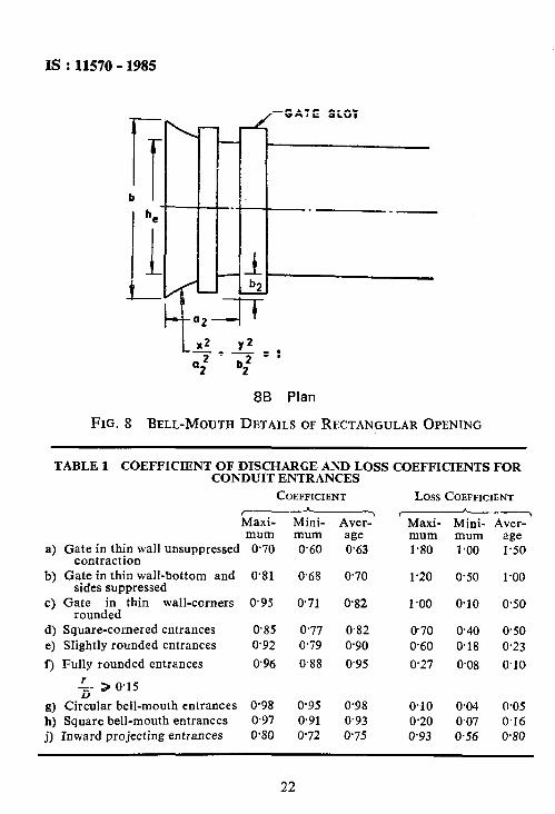
5.3 BelLMouth Opening and Transition - A typical sketch is shown in Fig. 8. In non-pressurized system the gate should be provided outside the bell-mouth end.
5.3.1 S hape nnd S ize of Opening - Entrance to the irrigation tunnel shall be designed to produce an acceleration similar to that found in a jet issuing from a sharp edged orifice. The surface shall be formed to natural contraction curve and the tunnel assumed to the size of orifice jet at its maximum contraction.
5.3.2 The normal contraction with coefficient of contraction C, as 0’6 shall be used in high-head inhtaliations and Ce as 0’7 for low-head installations in order to reduce the height of opening. Coefficients of discharge and loss coefficients for typical entrances for conduits are given in Table 1.
OF TUNNEL
8A Elevation
FIG. 8 BELL-MOUTH DETAILS OF RECTANGULAR OPENING 1 Contd
*Recommendations for design of trashracks for intakes. TCriteria for hydraulic design of hydropower intakes.
21
IS : 11570 - 1985
-*--_=I a2’ %f
8B Plan
FIG. 8 BELL-MOUTH DETAILS OF RECTANGULAR OPENING
TABLE 1 COEFFICIENT OF DISCHARGE AND LOSS COEFFICIENTS FOR CONDUIT ENTRANCES
COEFFICIENT Loss COEFFICIENT A
&axi- Mini- Aver? ---Y
Maxi- Mini- Aver-
a)
b)
cl
d) e) f)
mum mum age Gate in thin wall unsuppressed 0.70 0.60 0.63
contraction Gate in thin wall-bottom and 0.81 0.68 0.70
sides suppressed Gate in thin wall-corners 0.95 0.71 0.82
rounded Square-cornered entrances 0’85 0.77 0.82 Slightly rounded entrances 0.92 0.79 0.90
Fully rounded entrances 0.96 0.88 0.95
mum mum 1.80 l-00
1 .2 0 0 .5 0
age l-50
1.00
1 .oo 0.10
070 0.40 0.60 0.18
0.27 0.08
0.50
0.50 0.23
0.10
f3) Circular bell-mouth entrances 0.98 0.95 0.98 0.10 0.04 005 h) Square bell-mouth entrances 0.97 0.91 0.93 0.20 0.07 0.16
j) Inward projecting entrances 0’80 0’72 0.75 0.93 0.56 0.80
22

IS : 1 1 5 7 0 - 1 9 8 5
5.3.3 Opening Area
Opening area = Conduit area
ce cos +
where 4 =a2dgle of inclinationof centre line of conduit to horizontal,
Ce = Coefficient of contraction as defined in 53.2.
5.3.4 Entrance Curves for Circular Conduit s - For circular conduits, an elliptical entrance curve obtained from the following equation will satisfy the streamlining requirements:
where X and Y are coordinates measured parallel to and prependicular to the conduit centre line respectively, and D is the diameter of the conduit.
53.5 Entrance Curves for Rectangular Conduit 5.3.5.1 Height and w idth of opening The height is calculated by the distance above and below the inter-
section of the tunnel centre line with the face of the entrance ( see Fig .8)*.
Centre line to upper edge:
(1’21 t an2+t0’0847)~ + &- 1’10 tan 4 1 Centre line to lower edge:
hz = D I(
3 + 0’077 tan 4 >I h, = hl + h, 5.3.5.2 Shape of the opening - For a rectangular entrance with the
invert at the same elevation as the upstream floor and with curved guide piers at each side of the entrance openings, both the bottom and side contraction will be suppressed and a sharper contraction will take place at the top of the opening. For this condition, the top contraction curve is defined by the equation:
g2 + (0.sY7ZH,2 =’
where His the vertical height of the conduit downstream from the entrance shape.
23
IS :11570 - 1985
For rectangular or square openings
g+ ( **ZD )2 = l
where D is the vertical height of the conduit for defining top and bottom curves and is the horizontal width of the conduit for defining side curves.
The above mentioned formulae for rectangular/square conduit are .applicable when the centre line of the transition and centre line of conduit are the same.
For higher heads shape of the opening may be decided by model studies.
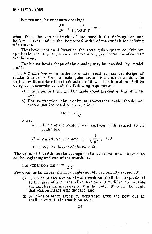
5.3.6 Transitions - In order to obtain most economical design of intake transitions from a rectangular section to a circular conduit, the vertical walls are flared in the direction of flow. The transition shall be designed in accordance with the following requirements:
4
b)
Transition or turns shall be made about the centre line of mass flow; For contraction, the maximum convergent angle should not exceed that indicated by the relation:
tan a = r u where
cy = Angle of the conduit wall surfaces with respect to its centre line,
V U 2 An arbitrary parameter = d/g-, and
H = Vertical height of the conduit.
The-value of V and Hare the average of the velocilies and dimensions at the beginning and end of the transition.
1 For expansion tan (Y = 2~
For usual installations, the flare angle should not normally exceed 10”.
c) The area of any section of the transition shall be proportional to the area of a jet at similar section and modified to provide the acceleration necessary to turn the water through the angle that section makes withthe face, and
d) All slots or other necessary departures from the neat outline shall be outside the transition zone.
24

IS : 11570 - 19855
5.4 Intake Gates and Air Vent
54.1 The intake gate slot shall be enclosed in a structure designed t@ guide the water into the rectangular opening without side contraction.
5.4.2 The upstream edge of the gate slot shall be at least 0’40 &from the nose, where be is the width of opening.
5.43 Where gates are located in a gate shaft, suitable transition from circular to rectangular gate slot shall be provided.
5.4.4 Size of Air Vent - An air vent is provided just downstream of the gate to prevent occurrence of excessive subatmospheric pressure. The air vent shall be so designed as to admit air with velocity not exceeding 50 m/s. The area of air vent is given by value of air demand divided by the maximum permissible velocity. Air demand shall be computed on the considerations of type of flow occurring downstream of gates, namely, spray flow, free flow, foamy flow, hydraulic jump forma- tion with free surface flow or hydraulic jump formation with pipe flow.
The air demand for different flow types in the conduit shall be computed with the help of the following formulae:
a) For hydraulic jump formation, B = 0’006 6 ( FIG - 1 )le4 where B is the ratio of volume flow rate of air to that of water, a& Kc is the Froude number at vena contracta;
b) For Spray flow, P = 0’2 FIG; and
c) For free flow P = 0’09 FIG
where
Q8 = air demand, Qw = discharge of water, and FIG = Froude number at vena contracta.
For hydraulic jump formation with channel flow and various types. of flows mentioned above, Fig. 9 may be used to compute air demand.
5.4.4.1 Prevent ion of air-blow s - The air-blows or return blows characterised by flow of air-water mixture, more or less in the form of- a geyser, have been observed at intakes similar to those shown in Fig. 6A and 6B. Sometimes these blows may be very violent and may result in blowing of t&e trashrack. fn some cases the trashrack may be lifted and drawn in the tunnel itself. Return blows &lay be prevented by the followiflg measures:
a) By providing larger open area of the trashrack;
25

IS:11570 - 1985
b) By providing another air-vent afte; the vertical bend in the outlet conduit; and
c) By washing away the air pockets frequently by releasing higher discharge in the tunnel.
5.4.4.2 Head losses in air ven t - Head loss in the air vent, specially in case of an unusually complicated vent layout containing a number of sharp bends and obstructions, shall be checked to determine whether the pressure drop exceeds 2 m of water in which case the vent size shall be increased suitably.
5.5 Approach Apron
5.5.1 The approach apron shall not be placed closer than 30 percent of the intake height, he, from the lower edge of the intake orifice.
50 LO
30
I 10 8 6 5
“a 6 * 3
2
1 1 2 3 L, s 7 10 20 30 a 50 70 100
(AC/A~)xt00 - Ac = Area of Flow at the Vena Contracta AT = Area of the Gutlet Tunnel
FIc = Froude’s Number at Vena Contracta
FIG. 9 AIR DEMAND CURVESFORSPRAY,FREEAND FOAMYFLOW
26

IS : 1 1 5 7 0 - 1 9 8 5
6. MISCELLANEOUS ARaANGEMENT
6.1 For intakes provided at high altitude above snow line, necessary provision for arresting the formation of ice cover on rack bars and gate shall be made for the free flow. The proposed de-icing arrangements shall conform to IS : 10021-1981*.
6.2 Floating ice shall be arrested by providing ice booms or concrete baffle cast intakes.
6.3 Racking Arrangement - Regular raking arrangement shall be provided for intakes where floating material is expected continuously.
6.4 Sediment Exclusion - In case of run-of-river development sediment exclusion devices such as de-silting basin or flushing ducts shall be provided.
6.5 Bypass and air vent arrangement should be provided in the intake between emergency gate and service gates.
APPENDIX A
( Cla u s e 51 .1 )
PROCEDURE FOR DETERMINING OPTIMUM SUBMERGENCE :OR LOCATION OF CENTRE LINE OF INTAKE
In order to ascertain whether at submergence ‘Hs’ of intake pipe of diameter D = 2~0 vortex will form at the intake or not proceed as under:
From the design data, the following parameters are known:
a) Effective head - HE,
b) Discharge corresponding to effective head HE - Q, and
c) Submergence of the intake - Hs.
*Guidelines for de-icing system for hydraulic installations.
27

IS : 1 1 5 7 0 - 1 9 8 5
c OF INTAKE SHAFT
AKE BENCti
INTAKE SHAFT D= 2ro
HE = Effeclive head=Res.‘level-head losses up to control gate
Step I Determine coefficient of discharge, C, from
C = Q/A%'2 gffE
Step II At any ccnvenient distance r from the centre line of the intake, such that r/D == 3, 4, 5 or 6, compute
velocity, Ve from the correlation: tangential
Step III Evaluate VRr2
Q Step IV Enter Fig.
point lies 7A plot of Ver2/Q verms C, and examine; if this . _ above the particular curve corresponding to the
adopted value of r/D, no vortex will form. below the curve vortex will form.
If this point lies
Hs = 3’45 J’er 2 -- ( > 2g r0
.Step V To determine the optimum water cover or submergence repeat to the above steps till the point corresponding to the computed values of C and Ver2/Q lies on the particular r/D curve. For the case of horizontal intake, Fig. 7B may be made use of.
28

AMENDMENT NO. 1 MAY 2013
TO
IS 11570 : 1985 CRITERIA FOR HYDRAULIC DESIGN OF
IRRIGATION INTAKE STRUCTURES
(Page 19 and 20, Fig. 7) — Substitute the following for the existing figure:
7A FOR VERTICAL INTAKES
1

Amendment No. 1 to IS 11570 : 1985
7B FOR HORIZONTAL INTAKES
FIG. 7 DIAGRAMS FOR DETERMINING OPTIMUM SUBMERGENCE
2

Amendment No. 1 to IS 11570 : 1985
(Page 21, Fig 8) –– Substitute the following figure for the existing:
8A ELEVATION
FIG. 8 BELL-MOUTH DETAILS OF RECTANGULAR OPENING
Contd… (Page 22, Fig 8) –– Substitute ‘be’ for ‘he’ (Page 23, clause 5.3.5.1) –– Insert the following at the end: ‘Width of the opening = be = Area of opening/ he’ (WRD 14)
Reprography Unit, BIS, New Delhi, India 3