Loke Uei Tan (@lokeuei) Sr. Tech Product Manager Developer Experience.

IRT807
OFF
ZERO
kHz
Temp
SMOOTH
mV
mA
INSU
LATION
V
V
50V
1000V
INSULATION TESTER
Apo
MIN/MAX
LOCK
Hz
Test Voltage
F C
SELECT
TEST
RANGE
PI/DAR
A-HOLD
0 0.1 M 1 M 10 M 100 M 1 G 2 G
VDC
M
INSTRUCTION MANUALENGLISH
IRT807
1000V AC/DC Digital Insulation Resistance Tester
1-800-547-5740www.ueitest.com • email: [email protected]


3
TABLE OF CONTENTS
FEATURES ..................................................................................................................................................5
GENERAL SPECIFICATIONS ..................................................................................................................5
IMPORTANT SAFETY WARNINGS .......................................................................................................6
SYMBOLS ..................................................................................................................................................7
CATEGORY DEFINITIONS ........................................................................................................................7
OVERVIEW .......................................................................................................................................... 8 - 9
OPERATING INSTRUCTIONS
Voltage: <1000V AC ................................................................................................................... 9
Voltage: with 1kHz “low-pass” filter <1000V ..............................................................................10
Voltage: <1000V DC .......................................................................................................................10
DC mV: 1mV to 400mV ...................................................................................................................11
Temperature: -328˚ to 2462˚F (-200˚ to 1350˚C) ...........................................................................11
Resistance ......................................................................................................................................12
Continuity ........................................................................................................................................12
Diode Test ......................................................................................................................................13
Capacitance ....................................................................................................................................13
mAmps AC/DC .......................................................................................................................... 14
Frequency .......................................................................................................................................14
Earth-bond Resistance ..................................................................................................................15
Insulation Resistance/ 1000V/ 500V/ 250V/ 100V/ 50V ........................................................... 16
Measuring Polarization Index and Dielectric Absorption Ratios ................................................17
Test Lead Notes ..............................................................................................................................17
Testing the Fuse ..............................................................................................................................18
Battery Replacement .....................................................................................................................18
Fuse Replacement ...........................................................................................................................18
DISPOSAL ................................................................................................................................................20
CLEANING ................................................................................................................................................20
STORAGE ................................................................................................................................................20
WARRANTY ..............................................................................................................................................20


5
FEATURES
• Insulation Resistance 2.0GΩ
• Earth-bond Resistance 20.00kΩ
• 1000V AC/DC
• Resistance 40MΩ
• Capacitance 10,000μF
• Frequency 99.99kHz
• Continuity and Diode test
• mAmps
• Temperature: -328˚ to 2462˚F (-200˚ to 1350˚C)
• PI/DAR test
• A-Hold/ Hold
• Zero reading
• Lock reading
• Rotary style selector
• Protective rubber boot
• Kick stand
• Test lead holders
• Remote probe
• Auto power off
• Backlit Display
• Worklight
GENERAL SPECIFICATIONS
• Operating Temperature: 32˚ to 122˚F (0˚ to 50˚C)
• Storage Temperature: 14˚ to 122˚F (-10˚ to 50˚C)
• Operating Humidity: <75%
• Operating Altitude: 6,526 ft (2000m)
• Pollution Degree: 2
• Over range: “OFL” is displayed
• Backlight: Yes
• Refresh Rate: 3/sec
• Dimensions: 8.27” x 3.52” x 2.17”
• Item Weight: 1.283 lbs
• Calibration: Recommended annually
• CAT Rating: CATIV 600V/ CATIII 1000V
• Certifications: CATIV 600V/CATIII 1000V, cETLus 3rd Edition, CE Conformity, IP42, RoHS, IEC/EN61010-1: 2010, 6’ Drop Protection
• Battery Type: (AA) 4
• Test Leads: Silicone test leads w/ alligator clips (red and black) (ATL57), Remote Probe
• Accuracy: ± (% of reading + # of least significant digits)
• Bargraph: 30 segment
6
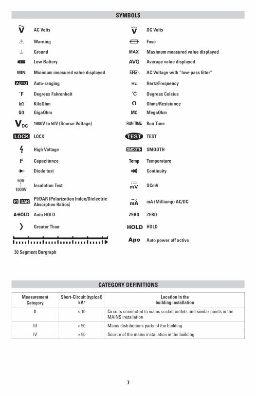
IMPORTANT SAFETY WARNINGS WARNING
Read entire Safety Notes section regarding potential hazard and proper instructions before using this meter. In this manual the word “WARNING” is used to indicate conditions or actions that may pose physical hazards to the user. The word “CAUTION” is used to indicate conditions or actions that may damage this instrument.
WARNING
To ensure safe operation and service of the tester, follow these instructions. Failure to observe these warnings can result in severe injury or death.
WARNING• Before each use, verify meter operation by measuring a known voltage.• Never use the meter on a circuit with voltages that exceed the category based rating of this meter. • Do not use this meter during electrical storms or in wet weather.• Do not use the meter or test leads if they appear damaged. • Ensure meter leads are fully seated and keep fingers away from the metal probe contact when making measurements. Always grip the leads behind the finger guards molded into the probe.• Do not open the meter to replace batteries while the probes are connected. • To avoid false readings that can lead to electrical shock, replace batteries if a low battery indicator appears. • Unless measuring voltage, shut off and lockout power before measuring resistance.• Always adhere to national and local safety codes. Use proper personal protective equipment (PPE) to prevent shock and arc blast injury where hazardous live conductors are exposed.• Always turn off power to a circuit or assembly under test before cutting, unsoldering or breaking the current path. Even small amounts of current can be dangerous.• Always disconnect the live test lead before disconnecting the common test lead from the circuit. • In the event of electrical shock, ALWAYS bring the victim to the emergency room for evaluation, regardless of victim’s apparent recovery. Electrical shock can cause unstable heart rhythms that may need medical attention.• If any of the following occur during testing, turn off the power source to the circuit being tested: arching, flame, smoke, extreme heat, smell of burning materials or discoloration or melting of components.
WARNING
Higher voltages require greater awareness of physical safety hazards. Before connecting the test leads; turn off power to the circuit under test, set meter to the desired function and range; connect the test leads to the meter first, then connect to the circuit under test. Reapply power. If an erroneous reading is observed, disconnect power immediately and recheck all settings and connections.
WARNING
This meter is designed for trade professionals who are familiar with the hazards of their trade. Observe all recommended safety procedures that include proper lockout utilization and use of personal protective equipment that includes safety glasses, gloves and flame resistant clothing.
7
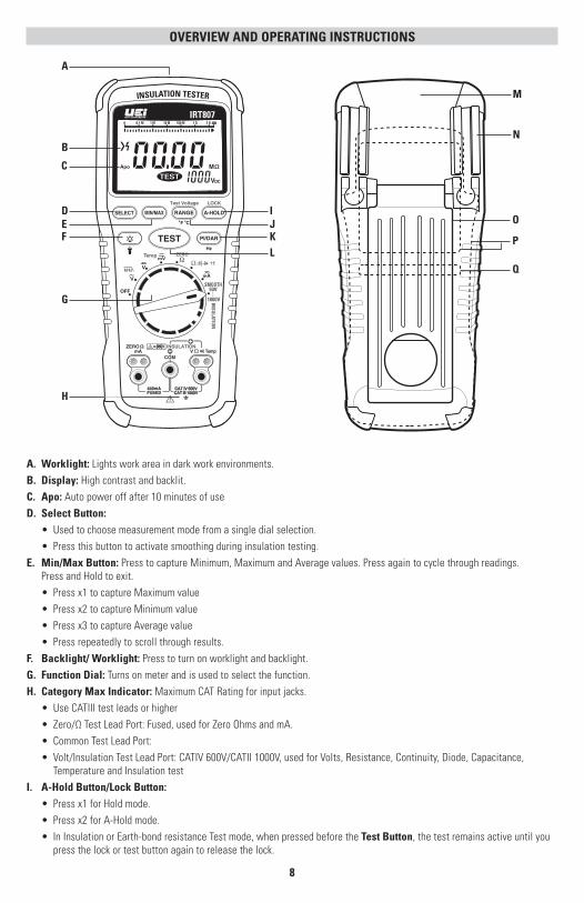
SYMBOLS
AC Volts DC Volts
Warning Fuse
Ground Maximum measured value displayed
Low Battery AVG Average value displayed
Minimum measured value displayed k AC Voltage with “low-pass filter”
Auto-ranging Hertz/Frequency
Degrees Fahrenheit Degrees Celsius
kΩ KiloOhm Ohms/Resistance
GΩ GigaOhm MΩ MegaOhm
DC 1000V to 50V (Source Voltage) RUN TIME Run Time
LOCK TEST
High Voltage SMOOTH
F Capacitance Temp Temperature
Diode test ContinuitySMOOTH
INSU
LATION
50V
1000VInsulation Test mV DCmV
PI/DAR (Polarization Index/Dielectric Absorption Ratios) mA (Milliamp) AC/DC
Auto HOLD ZERO ZERO
Greater Than HOLD
Auto power off active
30 Segment Bargraph
Measurement Category
Short-Circuit (typical) kAa
Location in the building installation
II < 10 Circuits connected to mains socket outlets and similar points in the MAINS installation
III < 50 Mains distributions parts of the building
IV > 50 Source of the mains installation in the building
CATEGORY DEFINITIONS
8
A. Worklight: Lights work area in dark work environments.B. Display: High contrast and backlit. C. Apo: Auto power off after 10 minutes of useD. Select Button: • Used to choose measurement mode from a single dial selection. • Press this button to activate smoothing during insulation testing.E. Min/Max Button: Press to capture Minimum, Maximum and Average values. Press again to cycle through readings. Press and Hold to exit. • Press x1 to capture Maximum value • Press x2 to capture Minimum value • Press x3 to capture Average value • Press repeatedly to scroll through results.F. Backlight/ Worklight: Press to turn on worklight and backlight.G. Function Dial: Turns on meter and is used to select the function.H. Category Max Indicator: Maximum CAT Rating for input jacks. • Use CATIII test leads or higher • Zero/Ω Test Lead Port: Fused, used for Zero Ohms and mA. • Common Test Lead Port: • Volt/Insulation Test Lead Port: CATIV 600V/CATII 1000V, used for Volts, Resistance, Continuity, Diode, Capacitance, Temperature and Insulation testI. A-Hold Button/Lock Button: • Press x1 for Hold mode. • Press x2 for A-Hold mode. • In Insulation or Earth-bond resistance Test mode, when pressed before the Test Button, the test remains active until you press the lock or test button again to release the lock.
OVERVIEW AND OPERATING INSTRUCTIONS
IRT807
OFF
ZERO
kHz
Temp
SMOOTH
mV
mA
INSU
LATION
V
V
50V
1000V
INSULATION TESTER
Apo
MIN/MAX
LOCK
Hz
Test Voltage
F C
SELECT
TEST
RANGE
PI/DAR
A-HOLD
0 0.1 M 1 M 10 M 100 M 1 G 2 G
VDC
M
F
H
K
B
A
L
D IE
G
J
M
N
O
Q
P
C

9
J. Range/Test Voltage/Temperature Scale Button: • Press and hold to return to Auto Ranging mode • Press to select desired voltage • Press to select ˚F or ˚CK. PI/DAR/Hz (Polarization Index/Dielectric Absorption Ratio) Button: Use PI for test of insulation deterioration and DAR for extended insulation resistance test. • Press x1 for PI mode. • Press x2 for DAR mode. • Press for Hz/Frequency measurement in AC Volts mode and AC mA mode.L. Test Button: Initiate test functionM. Protective Rubber Boot: With molded comfortable grip.N. Test Lead Holders: For hand-free use and storage of the test probes.O. Kick Stand: For easy viewing of screen when testing.P. Battery and Fuse Cover (under protective rubber boot)Q. Serial Number (under kick stand)
• Default = • Press x1 = k
Voltage: <1000V AC
IRT807
OFF
ZERO
kHz
Temp
SMOOTH
mV
mA
INSU
LATION
V
V
50V
1000V
INSULATION TESTER
MIN/MAX
LOCK
Hz
Test Voltage
F C
SELECT
TEST
RANGE
PI/DAR
A-HOLD
Apo
V
WARNING• Use CATIII rated Test leads or higher.• Do not attempt to measure more than 1000V AC.• Keep hands below finger guards when measuring high voltage levels.
Features: MIN/MAX
Test Voltage
F C
RANGE SELECT
LOCK
A-HOLD
Hz
PI/DAR
AC Volts (45Hz to 5kHz)RANGE RESOLUTION ACCURACY (45Hz to 400Hz) ACCURACY (400Hz to 5kHz)400mV 0.1mV
±(1.0% +5 dgts) ±(2.0% + 3 dgts) 4V 0.001V
40V 0.01V
400V 0.1V±(2.0% + 3 dgts) 1
1000V 1V ±(2.0% + 3 dgts)
1.1kHz bandwidthInput impedance 10MΩ (nominal), <100pF, AC-coupledOverload protection AC 1000V rms or DC
SELECT

10
IRT807
OFF
ZERO
kHz
Temp
SMOOTH
mV
mA
INSU
LATION
V
V
50V
1000V
INSULATION TESTER
MIN/MAX
LOCK
Hz
Test Voltage
F C
SELECT
TEST
RANGE
PI/DAR
A-HOLD
Apo
V
IRT807
V
Apo
Voltage: with 1kHz “low-pass” filter <1000V
The IRT807 is equipped with an AC “low-pass” filter. When measuring AC voltage press the Select Button to activate the “low pass” filter function. The meter continues to measure in the selected AC mode, but the signal passes through the filter that blocks any unwanted frequencies above 1kHz. The “low-pass” filter can improve measurement performance on composite sine waves that are typically generated by frequency motor drives and inverters.
WARNING• Use CATIII rated Test leads or higher.• Do not attempt to measure more than 1000V AC.• Keep hands below finger guards when measuring high voltage levels.
Features: MIN/MAX
Test Voltage
F C
RANGE SELECT
LOCK
A-HOLD
Hz
PI/DAR
Voltage: <1000V DC
WARNING• Use CATIII rated Test leads or higher.• Do not attempt to measure more than 1000V DC.• Keep hands below finger guards when measuring high voltage levels.
Features: MIN/MAX
Test Voltage
F C
RANGELOCK
A-HOLD
DC VoltsRANGE RESOLUTION ACCURACY4V 0.001V
±(0.2% +3 dgts) 40V 0.01V400V 0.1V1000V 1V ±(0.3% +6 dgts)
Accuracies apply to 100% of rangeInput impedance 10MΩ (nominal), <100pFOverload protection AC 1000V rms or DC

11
IRT807
OFF
ZERO
kHz
Temp
SMOOTH
mV
mA
INSU
LATION
V
V
50V
1000V
INSULATION TESTER
Apo
MIN/MAX
LOCK
Hz
Test Voltage
F C
SELECT
TEST
RANGE
PI/DAR
A-HOLD
0 0.1 M 1 M 10 M 100 M 1 G 2 G
VDC
M
IRT807
Apo
F
IRT807
OFF
ZERO
kHz
Temp
SMOOTH
mV
mA
INSU
LATION
V
V
50V
1000V
INSULATION TESTER
Apo
MIN/MAX
LOCK
Hz
Test Voltage
F C
SELECT
TEST
RANGE
PI/DAR
A-HOLD
0 0.1 M 1 M 10 M 100 M 1 G 2 G
VDC
M
IRT807
Apo
mV
WARNING• Use CATIII rated Test leads or higher.• Do not attempt to measure more than 400mV DC.• Keep hands below finger guards when measuring high voltage levels.
Features: MIN/MAX
Test Voltage
F C
RANGE
LOCK
A-HOLD SELECT
DC MILLIVOLTSRANGE RESOLUTION ACCURACY400mV DC 0.1mV ±(0.2% + 3 dgts)
Temperature: -328˚ to 2462˚F (-200˚ to 1350˚C)
Fahrenheit is the default temperature measurement scale. Press the Range Button to switch to Celsius scale.
TEMPERATURERANGE RESOLUTION ACCURACY1
-328˚ to 999˚F (-200˚ to 999˚C) 0.1˚F (0.1˚C) ±(1.5% +3.6˚F (1.5% +2˚C))1000˚ to 2642˚F (1000˚ to 1350˚C) 1˚F (1˚C) ±(1.5% +3˚F (1.5% +2˚C))
1 Accuracies apply following 90 minutes setting time after a change in the ambient temperature of the instrument
DC mV: 1mV to 400mV
• Default = mV
• Press x1 = Temp
• Default = mV
• Press x1 = Temp
mV
mV
SELECT
SELECT
Features: MIN/MAX
Test Voltage
F C
RANGE
LOCK
A-HOLD SELECT
Temp

12
Resistance
WARNING• Do not measure resistance on a live circuit.
Features: SELECT
LOCK
A-HOLD MIN/MAX Test Voltage
F C
RANGE
OHMSRANGE RESOLUTION ACCURACY400Ω 0.1Ω
±(0.3% +5 dgts)4kΩ 0.001kΩ40kΩ 0.01kΩ400kΩ 0.1kΩ
±(0.7% +5 dgts)4MΩ 0.001MΩ40MΩ 0.01MΩ ±(1.2% +10 dgts)
1. Accuracies apply from 0 to 100% of rangeOverload protection AC 600V rms or DCShort circuit current <1.0mA
IRT807
OFF
ZERO
kHz
Temp
SMOOTH
mV
mA
INSU
LATION
V
V
50V
1000V
INSULATION TESTER
Apo
MIN/MAX
LOCK
Hz
Test Voltage
F C
SELECT
TEST
RANGE
PI/DAR
A-HOLD
0 0.1 M 1 M 10 M 100 M 1 G 2 G
VDC
M
IRT807
Apo
• Default = • Press x1 = • Press x2 = • Press x3 =
SELECT
IRT807
OFF
ZERO
kHz
Temp
SMOOTH
mV
mA
INSU
LATION
V
V
50V
1000V
INSULATION TESTER
Apo
MIN/MAX
LOCK
Hz
Test Voltage
F C
SELECT
TEST
RANGE
PI/DAR
A-HOLD
0 0.1 M 1 M 10 M 100 M 1 G 2 G
VDC
M
IRT807
Apo
• Default = • Press x1 = • Press x2 = • Press x3 =
Continuity
SELECT
WARNING• Do not measure resistance on a live circuit.• Beeper sounds constant as long as circuit is complete.• Beeper sounds when a short (<40Ω) is detected.
Features: SELECT
LOCK
A-HOLD MIN/MAX
RANGE RESOLUTION ACCURACY OVERLOAD PROTECTION
400.0Ω 0.1Ω Approx. 40Ω 600V

13
IRT807
OFF
ZERO
kHz
Temp
SMOOTH
mV
mA
INSU
LATION
V
V
50V
1000V
INSULATION TESTER
Apo
MIN/MAX
LOCK
Hz
Test Voltage
F C
SELECT
TEST
RANGE
PI/DAR
A-HOLD
0 0.1 M 1 M 10 M 100 M 1 G 2 G
VDC
M
IRT807
Apo
V
• Default = • Press x1 = • Press x2 = • Press x3 =
SELECT
Features: SELECT
LOCK
A-HOLD MIN/MAX
RANGE RESOLUTION ACCURACY OVERLOAD PROTECTION
3V 0.001V ±(2% +1 dgts) 600V
CAUTIONDischarge all high-voltage capacitors before testing diodes. Large value capacitors should be discharged through an appropriate resistance load.
Diode Test
IRT807
OFF
ZERO
kHz
Temp
SMOOTH
mV
mA
INSU
LATION
V
V
50V
1000V
INSULATION TESTER
Apo
MIN/MAX
LOCK
Hz
Test Voltage
F C
SELECT
TEST
RANGE
PI/DAR
A-HOLD
0 0.1 M 1 M 10 M 100 M 1 G 2 G
VDC
M
IRT807
Apo
F
Features: SELECT
LOCK
A-HOLD MIN/MAX
Test Voltage
F C
RANGE
CAPACITANCERANGE RESOLUTION ACCURACY OVERLOAD PROTECTION10.00nF 0.01nF
±(2.5% +5 dgts)600V
100.0nF 0.1nF1.000µF 0.001µF10.00µF 0.01µF100.00µF 0.1µF1000µF 1µF
±(3% +5 dgts)10000µF 1µF
WARNINGCapacitors should be completely discharged prior to testing. Some electronic devices use capacitors in circuits that are designed to increase voltage. By design, a capacitor stores energy. If a capacitor has been charged at greater than 600 volts, attempting to measure it may damage your meter. Larger capacitors may store enough energy to cause injury if they are discharged through the body. Use a conductive device to dissipate the charge on capacitors. Large capacitors should be “bled” by using a resistive load between terminals to slowly eliminate the charge. Smaller capacitors may be directly shorted using a metallic object.
Capacitance
• Default = • Press x1 = • Press x2 = • Press x3 =
SELECT
14
IRT807
OFF
ZERO
kHz
Temp
SMOOTH
mV
mA
INSU
LATION
V
V
50V
1000V
INSULATION TESTER
Apo
MIN/MAX
LOCK
Hz
Test Voltage
F C
SELECT
TEST
RANGE
PI/DAR
A-HOLD
0 0.1 M 1 M 10 M 100 M 1 G 2 G
VDC
M
IRT807
Apo
mA
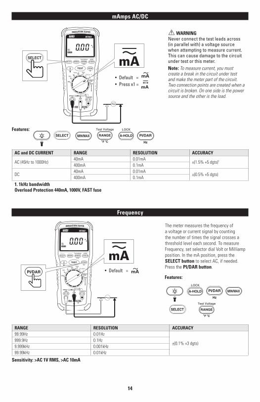
• Default = mA
• Press x1 = mA
SELECT
mAmps AC/DC
WARNINGNever connect the test leads across (in parallel with) a voltage source when attempting to measure current. This can cause damage to the circuit under test or this meter. Note: To measure current, you must create a break in the circuit under test and make the meter part of the circuit. Two connection points are created when a circuit is broken. On one side is the power source and the other is the load.
Features: SELECT
MIN/MAX
Test Voltage
F C
RANGE LOCK
A-HOLD
Hz
PI/DAR
AC and DC CURRENT RANGE RESOLUTION ACCURACY
AC (45Hz to 1000Hz)40mA 0.01mA
±(1.5% +5 dgts)1
400mA 0.1mA
DC40mA 0.01mA
±(0.5% +5 dgts)400mA 0.1mA
1. 1kHz bandwidthOverload Protection 440mA, 1000V, FAST fuse
IRT807
OFF
ZERO
kHz
Temp
SMOOTH
mV
mA
INSU
LATION
V
V
50V
1000V
INSULATION TESTER
Apo
MIN/MAX
LOCK
Hz
Test Voltage
F C
SELECT
TEST
RANGE
PI/DAR
A-HOLD
0 0.1 M 1 M 10 M 100 M 1 G 2 G
VDC
M
IRT807
Apo
mA
Frequency
RANGE RESOLUTION ACCURACY99.99Hz 0.01Hz
±(0.1% +3 dgts)999.9Hz 0.1Hz9.999kHz 0.001kHz99.99kHz 0.01kHz
Sensitivity: >AC 1V RMS, >AC 10mA
The meter measures the frequency of a voltage or current signal by counting the number of times the signal crosses a threshold level each second. To measure Frequency, set selector dial Volt or Milliamp position. In the mA position, press the SELECT button to select AC, if needed. Press the PI/DAR button.
PI/DAR • Default = mAFeatures:
LOCK
A-HOLDHz
PI/DAR MIN/MAX
Test Voltage
F C
RANGESELECT

15
Earth-bond Resistance
IRT807
OFF
ZERO
kHz
Temp
SMOOTH
mV
mA
INSU
LATION
V
V
50V
1000V
INSULATION TESTER
Apo
MIN/MAX
LOCK
Hz
Test Voltage
F C
SELECT
TEST
RANGE
PI/DAR
A-HOLD
0 0.1 M 1 M 10 M 100 M 1 G 2 G
VDC
M
IRT807
Apo
• Default = • Press x1 = ZERO
SELECT
NOTE: Measurements can be adversely affected by impedances of additional operating circuits connected in parallel or transient currents.
1. Insert test leads into the Zero/Ω and Com input ports.2. Turn the rotary dial selector to the Zero/Ω position.3. Short the test leads together. Press the SELECT Button and wait until ZERO appears on the display. The tester measures the probes resistance, stores the value in memory and subtracts it from tests. The probes resistance is saved even when the tester is powered off. If the probes resistance is >2Ω, the resistance will not be saved.4. Connect the test leads to the circuit to be tested. The tester will automatically detect if the circuit is energized.5. The dashes (----) will display until the TEST Button is pressed and a valid resistance value is detected.6.The High Voltage symbol will display if greater than 2V AC/DC is present. If this is happens, the test is corrupted. Disconnect the test leads and remove power before testing again.7. Press and hold the TEST Button on the Meter or Remote Probe to start the test. The TEST symbol will appear on the display until the TEST Button is released. The resistance value is displayed until a new test is started or a different function or range is selected.
Features: TEST
LOCK
A-HOLD SELECT
NOTE: When the resistance is higher than the maximum display range the tester displays the > symbol and the maximum resistance for the range.
WARNINGNEVER test resistance on a live circuit. (Overload Protection: AC 2V rms or DC)
RANGE RESOLUTION ACCURACY 1
20.00Ω 0.01Ω
±(1.5% +3 dgts)200.0Ω 0.1Ω2000Ω 1Ω20.00kΩ 0.01kΩ
1. Accuracies apply from 0 to 100% of range2. Open Circuit Test Voltage: > 4.0V, < 8V3. Short Circuit Current: > 200.0 mA
16
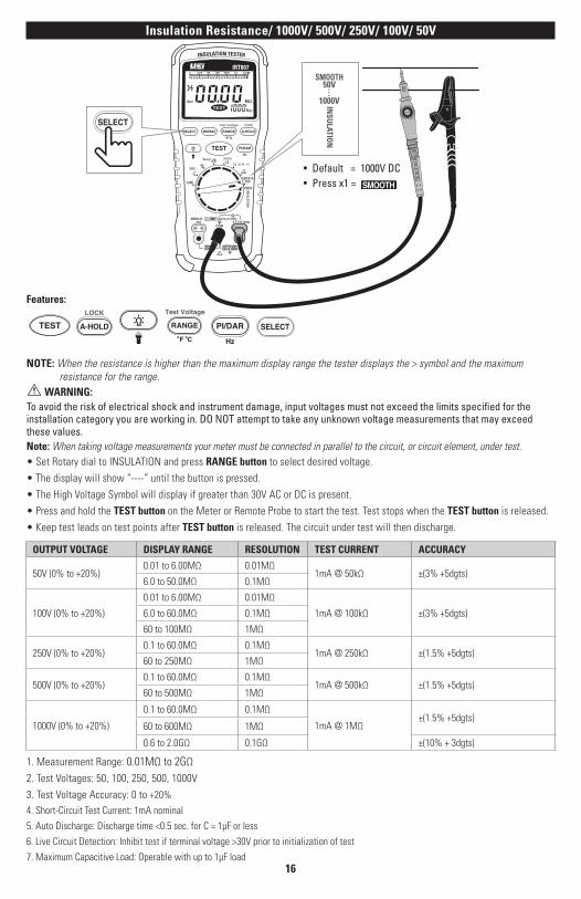
OUTPUT VOLTAGE DISPLAY RANGE RESOLUTION TEST CURRENT ACCURACY
50V (0% to +20%) 0.01 to 6.00MΩ 0.01MΩ
1mA @ 50kΩ ±(3% +5dgts)6.0 to 50.0MΩ 0.1MΩ
100V (0% to +20%)
0.01 to 6.00MΩ 0.01MΩ
1mA @ 100kΩ ±(3% +5dgts)6.0 to 60.0MΩ 0.1MΩ
60 to 100MΩ 1MΩ
250V (0% to +20%) 0.1 to 60.0MΩ 0.1MΩ
1mA @ 250kΩ ±(1.5% +5dgts)60 to 250MΩ 1MΩ
500V (0% to +20%) 0.1 to 60.0MΩ 0.1MΩ
1mA @ 500kΩ ±(1.5% +5dgts)60 to 500MΩ 1MΩ
1000V (0% to +20%)
0.1 to 60.0MΩ 0.1MΩ
1mA @ 1MΩ±(1.5% +5dgts)
60 to 600MΩ 1MΩ
0.6 to 2.0GΩ 0.1GΩ ±(10% + 3dgts)
Insulation Resistance/ 1000V/ 500V/ 250V/ 100V/ 50V
Features:
TESTLOCK
A-HOLD
Test Voltage
F C
RANGE
Hz
PI/DAR
SELECT
NOTE: When the resistance is higher than the maximum display range the tester displays the > symbol and the maximum resistance for the range.
WARNING: To avoid the risk of electrical shock and instrument damage, input voltages must not exceed the limits specified for the installation category you are working in. DO NOT attempt to take any unknown voltage measurements that may exceed these values.Note: When taking voltage measurements your meter must be connected in parallel to the circuit, or circuit element, under test.• Set Rotary dial to INSULATION and press RANGE button to select desired voltage.• The display will show “----” until the button is pressed.• The High Voltage Symbol will display if greater than 30V AC or DC is present.• Press and hold the TEST button on the Meter or Remote Probe to start the test. Test stops when the TEST button is released. • Keep test leads on test points after TEST button is released. The circuit under test will then discharge.
• Default = 1000V DC• Press x1 =
IRT807
OFF
ZERO
kHz
Temp
SMOOTH
mV
mA
INSU
LATION
V
V
50V
1000V
INSULATION TESTER
Apo
MIN/MAX
LOCK
Hz
Test Voltage
F C
SELECT
TEST
RANGE
PI/DAR
A-HOLD
0 0.1 M 1 M 10 M 100 M 1 G 2 G
VDC
M
SELECT
SMOOTH
INSU
LATION
50V
1000V
1. Measurement Range: 0.01MΩ to 2GΩ2. Test Voltages: 50, 100, 250, 500, 1000V3. Test Voltage Accuracy: 0 to +20%
4. Short-Circuit Test Current: 1mA nominal
5. Auto Discharge: Discharge time <0.5 sec. for C = 1µF or less
6. Live Circuit Detection: Inhibit test if terminal voltage >30V prior to initialization of test
7. Maximum Capacitive Load: Operable with up to 1µF load

17
Test Lead NotesCATIV 600V Measurement Locations
• Ensure the test lead shield is pressed firmly in place. Failure to use the CAT IV shield increases arc-flash risk.
CAT II Measurement Locations
• CAT IV shields may be removed for CAT II locations. This will allow testing on recessed conductors such as standard wall outlets. Take care not to lose the shields.
WARNING: Test Lead category protections apply only to test leads and should not be confused with the meter’s specific CAT rating. Observe the maximum category protection indicated on the meter the test leads are plugged into.
4mm
18mm
4mm
18mm
Measuring Polarization Index and Dielectric Absorption RatiosPolarization Index (PI) is the ratio of the 10-minute insulation resistance. Dielectric Absorption Ratio is the ratio of the 1-minute insulation resistance to the 30-second insulation resistance.
WARNING • Insulation tests should only be performed on
de-energized circuits. To measure polarization index or dielectric absorption ration; • Use insulation and COM Input ports.NOTE: Because of the time required to perform the PI and DAR tests, use of alligator clips is recommended.• Set rotary function dial to INSULATION position and press RANGE button to select desired voltage.• Press the PI/DAR button to select PI or DAR.• The display shows “----” until TEST button is pressed and a valid resistance is obtained.
IRT807
OFF
ZERO
kHz
Temp
SMOOTH
mV
mA
INSU
LATION
V
V
50V
1000V
INSULATION TESTER
MIN/MAX
LOCK
Hz
Test Voltage
F C
SELECT
TEST
RANGE
PI/DAR
A-HOLD
Apo
• Default =
SMOOTH
INSU
LATION
50V
1000V
• The High Voltage symbol warns if voltage of greater than 30V AC or DC is present. If High voltage is present, test is inhibited.• Press and release the TEST button on the Meter or the Remote Probe to start the test. During testing, the display shows the test voltage applied to the circuit under test. The high voltage symbol along with display showing resistance in MΩ or GΩ, the TEST icon appears on the lower portion of the display until the test is finished.• To interrupt PI or DAR test before it is completed, press TEST button. When you release the TEST button, the circuit under test will automatically be discharged through the tester.
Features: TEST
LOCK
A-HOLD
Test Voltage
F C
RANGE
Hz
PI/DAR SELECT
NOTE: Measurements can be adversely affected by impedances of additional operating circuits connected in parallel or transient currents.
TEST
PI/DAR
• Default = • Press x1 =

18
IRT807
OFF
ZERO
kHz
Temp
SMOOTH
mV
mA
INSU
LATION
V
V
50V
1000V
INSULATION TESTER
MIN/MAX
LOCK
Hz
Test Voltage
F C
SELECT
TEST
RANGE
PI/DAR
A-HOLD
Apo
V
TEST
Battery Replacement
Fuse Replacement
• When the batteries are too low for safe operation, the Low Battery indicator will display
• Remove protective rubber boot.
• Remove battery cover.• Replace the batteries (4 AA).• Replace the battery cover• Replace the protective rubber
boot.
• Remove protective rubber boot.• Remove battery cover.• Replace the fuse (F 440mA
1000V 1R 10kA).• Replace the battery cover.• Replace the protective rubber
boot.
Fuse
AA battery
AA battery
AA battery
AA battery
Fuse
AA battery
AA battery
AA battery
AA battery
Removed protective rubber boot.
Removed protective rubber boot.
Removed battery cover.
Removed battery cover.
Testing the Fuse
• Turn the rotary selector dial to ZERO/Ω position.• Press and hold the TEST button. If the display
shows “FUSE”, the fuse is bad and should be replaced. Please see Fuse Replacement section of this manual.
WARNING: • To avoid electrical shock or injury, remove the
test leads and any input signals/voltages before replacing the fuse.

DISPOSAL
CAUTION: This symbol indicates that equipment and its accessories shall be subject to separate collection and correct disposal.
CLEANING
Periodically clean your meter’s case using a damp cloth. DO NOT use abrasive, flammable liquids, cleaning solvents, or strong detergents as they may damage the finish, impair safety, or affect the reliability of the structural components.
STORAGE
Remove the batteries when instrument is not in use for a prolonged period of time. Do not expose to high temperatures or humidity. After a period of storage in extreme conditions exceeding the limits mentioned in the General Specifications section, allow the instrument to return to normal operating conditions before using it.
WARRANTY
The IRT807 is warranted to be free from defects in materials and workmanship for a period of 1 year from the date of purchase. If within the warranty period your instrument should become inoperative from such defects, the unit will be repaired or replaced at UEi’s option. This warranty covers normal use and does not cover damage which occurs in shipment or failure which results from alteration, tampering, accident, misuse, abuse, neglect or improper maintenance. Batteries and consequential damage resulting from failed batteries are not covered by warranty.
Any implied warranties, including but not limited to implied warranties of merchantability and fitness for a particular purpose, are limited to the express warranty. UEi shall not be liable for loss of use of the instrument or other incidental or consequential damages, expenses, or economic loss, or for any claim or claims for such damage, expenses or economic loss.
A purchase receipt or other proof of original purchase date will be required before warranty repairs will be rendered. Instruments out of warranty will be repaired (when repairable) for a service charge.
For more information on warranty and service, contact:
www.ueitest.com • Email: [email protected]
This warranty gives you specific legal rights. You may also have other rights, which vary from state to state.
Copyright © 2019 Kane USA Inc. All Rights Reserved. 17420 0119