IRRADIATION EMBRITTLEMENT MITIGATION · AMES Report No. 1 EUR 16072 EN IRRADIATION EMBRITTLEMENT...
90
AMES Report No. 1 EUR 16072 EN IRRADIATION EMBRITTLEMENT MITIGATION Tapio Planman Reijo Pelli Kari Törrönen European Network on Ageing Materials Evaluation and Studies Espoo, September 1994 VTT Manufacturing Technology P.O. Box 1704, FIN-02044 VTT, Finland Tel. 90-4561, Telefax 90-456 7002
Transcript of IRRADIATION EMBRITTLEMENT MITIGATION · AMES Report No. 1 EUR 16072 EN IRRADIATION EMBRITTLEMENT...

AMES Report No. 1
EUR 16072 EN
IRRADIATION EMBRITTLEMENTMITIGATION
Tapio PlanmanReijo Pelli
Kari Törrönen
European Network onAgeing Materials Evaluation and Studies
Espoo, September 1994
VTT Manufacturing TechnologyP.O. Box 1704, FIN-02044 VTT, Finland
Tel. 90-4561, Telefax 90-456 7002
1
ABSTRACT
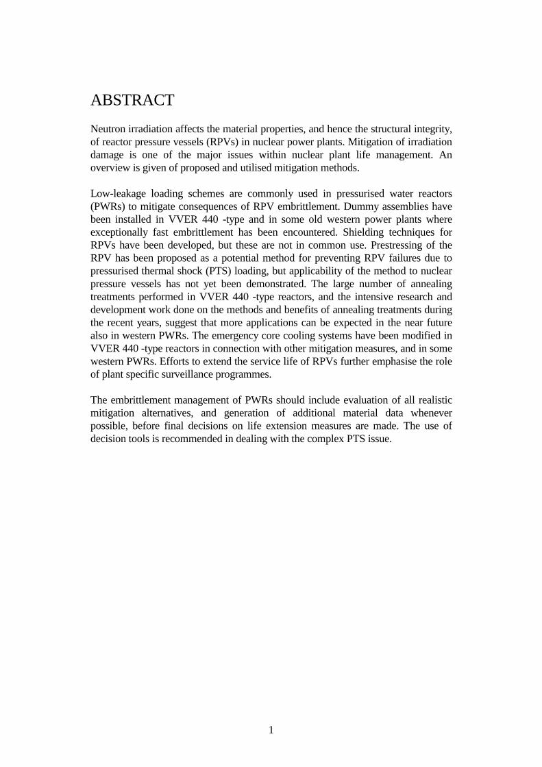
Neutron irradiation affects the material properties, and hence the structural integrity,of reactor pressure vessels (RPVs) in nuclear power plants. Mitigation of irradiationdamage is one of the major issues within nuclear plant life management. Anoverview is given of proposed and utilised mitigation methods.
Low-leakage loading schemes are commonly used in pressurised water reactors(PWRs) to mitigate consequences of RPV embrittlement. Dummy assemblies havebeen installed in VVER 440 -type and in some old western power plants whereexceptionally fast embrittlement has been encountered. Shielding techniques forRPVs have been developed, but these are not in common use. Prestressing of theRPV has been proposed as a potential method for preventing RPV failures due topressurised thermal shock (PTS) loading, but applicability of the method to nuclearpressure vessels has not yet been demonstrated. The large number of annealingtreatments performed in VVER 440 -type reactors, and the intensive research anddevelopment work done on the methods and benefits of annealing treatments duringthe recent years, suggest that more applications can be expected in the near futurealso in western PWRs. The emergency core cooling systems have been modified inVVER 440 -type reactors in connection with other mitigation measures, and in somewestern PWRs. Efforts to extend the service life of RPVs further emphasise the roleof plant specific surveillance programmes.
The embrittlement management of PWRs should include evaluation of all realisticmitigation alternatives, and generation of additional material data wheneverpossible, before final decisions on life extension measures are made. The use ofdecision tools is recommended in dealing with the complex PTS issue.

2
PREFACE
This report has been compiled at the VTT Manufacturing Technology as part of thestate-of-the-art review on irradiation embrittlement, surveillance and mitigationmethods carried out by the European Network for Ageing Materials Evaluation andStudies (AMES). The work is financed by the CEC DG XI through the contract"Centre d'Etudes de Saclay 91191 Gif Sur Yvette Cedex, Ref. 7220 3B018750,M. Soulat". The Finnish Centre provided additional financing for Radiation andNuclear Safety (STUK) and VTT.
Associated with this subject, reports are to be compiled within AMES also onthermal annealing and on the scientific basis of Russian and European approachesfor evaluating irradiation effects in reactor pressure vessels. The authors greatlyacknowledge Acad. Myrddin Davies and Dr. Colin English for conducting a peerreview for this report.

3
CONTENTS
ABSTRACT..................................................................................................................1PREFACE.....................................................................................................................2
1 INTRODUCTION ..................................................................................................42 FLUENCE RATE REDUCTION TECHNIQUES..............................................12
2.1 Core modification and/or reduction................................................................122.1.1 Description of methods.......................................................................122.1.2 Calculated cases for different cores ....................................................182.1.3 Special fuel designs.............................................................................20
2.2 Shielding of the pressure vessel......................................................................212.3 Factors affecting fluence rate reduction .........................................................252.4 Secondary consequences of reduced fluence rate ..........................................26
3 MODIFICATION OF EMERGENCY CORE COOLING ANDOTHER SYSTEMS..............................................................................................273.1 Pressurised thermal shocks.............................................................................273.2 Normal heatup and cooldown conditions.......................................................333.3 Low-temperature overpressure transients.......................................................343.4 High-temperature transients............................................................................38
4 ANNEALING .......................................................................................................394.1 Methods...........................................................................................................394.2 Accomplished annealings ...............................................................................394.3 Recovery and re-embrittlement of western RPV steels .................................414.4 Recovery and re-embrittlement of VVER 440 RPVs ....................................47
5 OTHER MITIGATION METHODS ...................................................................525.1 Prestressing .....................................................................................................525.2 Warm prestressing ..........................................................................................575.3 Weld replacement ...........................................................................................575.4 Replacement of the RPV ................................................................................575.5 Power reduction ..............................................................................................57
6 APPLICATIONS AT SOME NUCLEAR POWER PLANTS ...........................587 EVALUATION OF MITIGATION METHODS IN PWRs................................68
7.1 Applicability and use of different methods ....................................................697.2 Strategies and methods for managing irradiation embrittlement...................747.3 On research needs and experience..................................................................777.4 Recommendations for utilities........................................................................787.5 Research needs ...............................................................................................79
8 CONCLUSIONS ..................................................................................................81ACKNOWLEDGMENTS..........................................................................................82REFERENCES ..........................................................................................................82

4
1 INTRODUCTION
Reactor pressure vessel (RPV) integrity is assured by several arrangements includingthe setting of operational limits for normal and various transient conditions,surveillance of irradiation embrittlement of beltline materials, and in-serviceinspections and other maintenance procedures.
The critical loading conditions for RPVs are typically associated with differentpostulated emergency core cooling, i.e. pressurised thermal shock (PTS) events,during which the pressure vessel is subjected both to thermal stresses and to thosecaused by repressurisation. The temperature-pressure limits (operating windows) setfor heatup and cooldown stages may require operational restrictions due to the RPVembrittlement.
Many investigations of RPV failure probability have been put forward since 1982,when surveillance results from some operating plants showed that embrittlement ofa vessel material was faster than predicted. Of special concern were certain oldpressurised water reactors (PWRs), where predictions made by U.S. NuclearRegulatory Commission (NRC) showed that failure during a PTS transient could bepossible after only a few years of operation (Smock, 1982).
Recently, irradiation embrittlement mitigation has come under closer scrutiny as theoperating licenses of the oldest plants are due to expire within the next few decadesand plant life extension needs to be considered. If replacement of RPVs is excluded,remedial measures such as thermal annealing of the RPV may be needed for lifeextension in many old PWRs, besides possible preventive measures alreadyimplemented. At any rate, the most important measures are those assuring RPVintegrity during operating and possible accident conditions. Irradiationembrittlement is normally the most severe degradation mechanism in RPVs,although other mechanisms also exist (Gerard, 1990).
RPV embrittlement is caused mainly by the fast neutron flux from the core.Embrittlement depends also on the impurity contents of a RPV material. Differentguides have been developed to evaluate the fluence dependence of materials withcertain impurity contents. Federal Regulation 10CFR50.61 provides rules forevaluating the nil-ductility transition temperature (RTNDT) and upper shelf energy fordifferent steels and fluences (USNRC, 1988 and Shah et al., 1989).
In NRC Regulatory Guide 1.99 Revision 2, the transition temperature (at the CVN41 J energy level) is presented as a function of Cu and Ni contents of the steel andthe neutron fluence. The guide differentiates between base and weld materials. Theupper shelf energy, which is used to characterise RPV materials in operatingconditions, is calculated as a function of the Cu content and fluence. Guide 1.99Rev. 2 has been compiled on the basis of surveillance test results from commercialU.S. power reactors, and has been found to give conservative estimates (Mager,1993). It is noteworthy that this guide excludes the effect of P, which is also adetrimental element. Predictive equations based upon irradiation data from testreactors and surveillance capsules have been provided also by Framatome (Mager,

5
1993). However, it is recommended that RPV embrittlement should be followed byplant-specific surveillance programmes.
Measures to mitigate irradiation embrittlement and reduce failure probability of theRPV have typically been directed towards following factors: 1) the material, 2) theenvironment, and 3) the stress state in the most severe loading situations and theprobability of such events.
1. In new RPVs the steel composition has been optimised (Leitz & Koban, 1989),meaning that the contents of Cu, P and some other impurities have been minimised.A high Ni content may also enhance irradiation embrittlement if impurity contents(P, Cu) are high enough. Thermal annealing has been used for old RPVs to recoverirradiation defects and mechanical properties.
2. Irradiation embrittlement can be mitigated efficiently in the early stages of RPVservice life by reducing the neutron fluence (hence the fluence rate) to the pressurevessel, without the need to reduce core power. Low-leakage fuel management, atleast in some form, is already applied in most PWRs, either for economic reasons orto mitigate irradiation embrittlement (Bagnal et al., 1984). Irradiation temperatureand fluence rate also affect the embrittlement rate.
3. Stress concentrations in the RPV during a postulated PTS event, i.e. the severityof PTS, should be minimised to reduce the RPV failure probability. Thermal stressescan be decreased by raising the emergency core cooling water temperature and/orincreasing mixing. Prestressing of the RPV, which has been suggested as a methodfor preventing PTS failures (detailed description given later), would provide oneway to reduce stresses. The probability of severe transient conditions should also beminimised.
As a consequence of advanced steel and RPV manufacturing techniques, irradiationembrittlement of the RPV is not expected to limit the service life of modern PWRs(Leitz & Koban, 1989). These have typically only a few circumferential welds in theRPV (welds are usually most susceptible to embrittlement due to their chemicalcomposition), low impurity contents in welds and base materials, and a low neutronfluence rate at the RPV due to the large water gap between the core and the RPVwall (Figs. 1 and 2). The effect of some of these factors on the 41 J transitiontemperature shift is shown in Fig. 3.

6
Fig. 1. Development of RPV dimensions and core configurations (KWU) (Leitz &Koban, 1989).
Fig. 2. Development of VVER-type RPV dimensions and core configurations(Štepánek & Šaroch, 1983 and Dragunov & Tyulpin, 1993).

7
Fig. 3. Effect of fluence reduction and material improvement on the transitiontemperature shift (Leitz & Koban, 1989).
Some old PWR vessels (built in 1960-70) are particularly susceptible toembrittlement (Leitz & Koban, 1989). Typical reasons are the high design end-of-life (EoL) fluence of the RPV, an unfavourable steel composition, or welds(circumferential and/or longitudinal) located in the beltline area. In older RPVs, highneutron fluence peaks often exist due to the typically small size of the core (lowsymmetry) and the relatively large size of fuel elements. Excessive embrittlementhas also been caused by weld materials with high impurity contents. In U.S. reactors,irradiation problems are associated both with longitudinal welds of the RPVsmanufactured from plates instead of ring forging, and with high Cu content of theweld materials (Fig. 4). In West-European power plants, the impure weld material isoften given as the major reason for fast embrittlement. In many western RPVs, theembrittlement rate is also enhanced by a high Ni content. In some old PWRs,embrittlement mitigation measures have had to be implemented to achieve theoriginal design service life of the RPV (Franklin & Marston, 1983).

8
Fig. 4. Critical weld locations in a typical U.S. PWR (Bagnal et al., 1984).
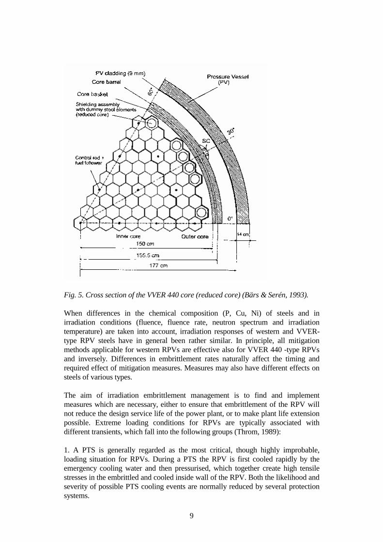
High embrittlement rates of the VVER 440/213 and 440/230 -type RPVs have beenattributed to high P and Cu contents of the welds and a high fluence rate at the RPV.In these RPVs, high Cu contents originate either from Cu plated electrodes used forwelding or the residual Cu of the filler material, or both (IAEA-TECDOC-659,1992). However, P is possibly a more important element due to its relatively highcontents. As the most critical site in VVER 440 RPVs has been considered thecircumferential weld locating in the beltline area (Fig. 2), but sites prone tosignificant degradation have been assessed to be also outlet/inlet andinstrumentation nozzles and flange closure studs, subjected both to irradiation andmechanical and thermal loads (IAEA-TECDOC-659, 1992). Due to the exceptionaldesign basis of the VVER 440 RPV, i.e. the requirement set for transporting ofvessels, the distance between the core and the RPV wall had to be made very small(Fig. 5), resulting in a high fluence rate at the RPV. As a consequence, only a fewVVER 440 plants are operated at full core (see Table 9, p. 66). On the other hand,the RPVs have been welded from ring forgings (of Cr-Mo-V steel) withoutlongitudinal welds, which simplifies the annealing treatment. The Ni contents of theRPV steels are also relatively low. Uncertainties about the material properties andchemical composition of the beltline weld are regarded as a concern in some claddedVVER 440 RPVs where the weld has been covered by protective surface layers withdifferent compositions (WWER-SC-081, Rev. July 1994). Samples taken near the(outer) surface of such a RPV weld are not always representative of the inner weldmaterial.
9
Fig. 5. Cross section of the VVER 440 core (reduced core) (Bärs & Serén, 1993).
When differences in the chemical composition (P, Cu, Ni) of steels and inirradiation conditions (fluence, fluence rate, neutron spectrum and irradiationtemperature) are taken into account, irradiation responses of western and VVER-type RPV steels have in general been rather similar. In principle, all mitigationmethods applicable for western RPVs are effective also for VVER 440 -type RPVsand inversely. Differences in embrittlement rates naturally affect the timing andrequired effect of mitigation measures. Measures may also have different effects onsteels of various types.
The aim of irradiation embrittlement management is to find and implementmeasures which are necessary, either to ensure that embrittlement of the RPV willnot reduce the design service life of the power plant, or to make plant life extensionpossible. Extreme loading conditions for RPVs are typically associated withdifferent transients, which fall into the following groups (Throm, 1989):
1. A PTS is generally regarded as the most critical, though highly improbable,loading situation for RPVs. During a PTS the RPV is first cooled rapidly by theemergency cooling water and then pressurised, which together create high tensilestresses in the embrittled and cooled inside wall of the RPV. Both the likelihood andseverity of possible PTS cooling events are normally reduced by several protectionsystems.

10
2. Normal heatup and cooldown stages, during which temperature and pressurechanges are restricted by the operating windows specified for the RPV. The size ofoperating windows and hence the operability of the plant is affected by the conditionof the RPV beltline region.
3. Low-temperature overpressure transients, during which the temperature-pressurelimits are exceeded temporarily. The likelihood of these events is reduced by variousprotection systems, which are discussed in greater detail later. An overpressuretransient may induce crack growth in the embrittled inside wall of the RPV.
4. High temperature transients may become critical for RPVs where the upper shelftoughness of the material has been significantly reduced by neutron irradiation.
In one accident scenario, thermal transients are created in the RPV due to cooling ofthe outside surface when cold water floods into the containment and comes intocontact with the RPV (Laaksonen, 1994).
Irradiation embrittlement management should always be considered as part of thelife management of the whole plant. This means that the necessity, costs, andoptimum timing of various embrittlement mitigation methods will also be affectedby the degradation and operation of other components such as steam generators.Some factors incorporated in irradiation embrittlement management are given inFig. 6.
The significance of uncertainties associated with determination of materialproperties and embrittlement rates, such as the chemical composition, irradiationdose, and conservatism of Charpy-V impact tests, is emphasised but a detailed studyon this subject is outside the scope of this work.
Approaches used for integrity analyses of RPVs in different countries are discussedby Griesbach (1993). In Finland, safety of RPVs is evaluated from the failureprobabilities in certain postulated accident situations using only measured materialproperties, e.g. the elastic-plastic KJc.
The measures already in use or proposed for extension of RPV technical service lifeconsist of operations reducing the fluence rate at the RPV, recovery annealing of theRPV material, modification of the emergency core cooling and related systems, aswell as other (proposed) operations. The use and applicability of these measures arereviewed in this report.

11

12
2 FLUENCE RATE REDUCTION TECHNIQUES
Two principles are available for reducing fluence accumulation in the RPV. Thecore, i.e. the irradiation source, can be modified or reduced to give a lower fluencerate. Another way is to place irradiation shields or reflectors between the core andthe RPV.
2.1 CORE MODIFICATION AND/OR REDUCTION
2.1.1 Description of methods
For any core configuration there are generally numerous possible loading schemesavailable. In general, to maximise core power the radial power distribution should beas even as possible. This can be achieved by following the OUT-IN scheme, wherethe fresh and most highly enriched fuel is placed for its first cycle on the coreperiphery and the exposed fuel in the interior (Bagnal et al., 1984). These proceduresincrease fission power density on the core periphery, where it is reduced by neutronleakage. Unfortunately, all actions to increase fission power density on the coreperiphery increase neutron leakage from the core and hence the fluence rate at theRPV.
The OUT-IN scheme was previously the standard loading scheme in PWRs. Thedisadvantages were poor neutron economy and fast embrittlement of RPVs(Franklin & Marston, 1983 and Bagnal et al., 1984). However, in some instanceslow-leakage fuel management has been followed for reasons of fuel cycle economics(Anderson & Whitmarsh, 1984).
The terms "low-leakage" and "low-fluence (or fluence rate) loading schemes" areused in the literature in different contexts. Low-leakage schemes are appliedtypically to minimise the overall neutron leakage from the core. The main objectiveof low-fluence schemes is to modify the circumferential neutron fluence ratedistribution in such a way that the fluence rate at the critical locations of the RPV isreduced. The critical locations, i.e. those restricting the RPV service life, aregenerally welds due to their chemical composition and subsequent fastembrittlement, but also the base material may become life limiting. In RPVs withoutlongitudinal welds, fluence reduction measures are applied for makingcircumferential fluence rate distribution more even, as in small cores this is typicallyvery uneven with no modifying actions. The circumferential fluence distribution inthe RPV of a 900 MWe reactor is shown in Fig. 7.

13
Fig. 7. Fluence distribution in a 900 MWe reactor pressure vessel (Gerard, 1990).
The situation is more complicated for RPVs with longitudinal welds, as these are notusually (fortunately) located at circumferential fluence peak areas. This means thatthe fluence rate distribution should be modified so that significant reduction in thefluence rate is achieved at a certain fixed location instead of only flattening thefluence rate profile. If "low fluence rate assemblies" are to be implemented forachieving this kind of reduction, the fuel assemblies to be replaced are notnecessarily those nearest the RPV wall. A consequence is generally that more fuelassemblies on the core periphery must be replaced by low fluence rate assemblies toachieve the desired effect on the fluence rate distribution (especially if the coresymmetry is desired to be maintained). In such cases some other location alsobecomes sensitively critical. Hence, fluence rate reduction at a fixed circumferentiallocation (e.g. longitudinal weld) is generally more difficult to achieve than the samereduction in a circumferential fluence rate peak (Stucker et al., 1983). The criticallocation of the RPV is often just on the inside surface of a longitudinal weld, if thisexists.
Besides the location of welds in the RPV, also the size and configuration of the coreaffect the applicability and possible benefits of different low-leakage (or low-fluence) schemes. The increase in power peaking due to a given low-leakage schemeis larger for small cores. In addition, in a large core more low-leakage loadingschemes are available than in a small one.
If there are only circumferential welds in the RPV, the fluence rate at the vessel canbe reduced most efficiently by reducing power in the critical peripheral fuelassemblies, i.e. in those nearest the RPV wall. Roughly 85% of the fluence to theRPV is estimated to come from the core peripheral assemblies (Carew & Lois,1991). The contribution of some adjacent assemblies to the fluence of twolongitudinal welds is shown in Fig. 8.

14
Fig. 8. Contribution (%) of some fuel assemblies to the fluence of welds at positions105o and 345o (Anderson & Whitmarsh, 1984).
The following procedures are applicable for reducing the fluence rate (Franklin &Marston, 1983; Bagnal et al., 1984; Moylan & Balkey, 1987; Moylan et al., 1987;Leitz & Koban, 1989):
1. Low-leakage fuel management. Some or all of the peripheral fresh fuelassemblies are replaced by low reactivity fuel assemblies, i.e. those having spent oneto three cycles in the reactor.
2. Some of the peripheral fuel assemblies are replaced by dummy assemblies,which contain stainless steel or zirconium rods instead of UO2 pellets. Eitherpartially or fully replaced assemblies can be used. Typically 5-10% of the fuelassemblies need replacing to maintain circumferential symmetry.
3. Installation of neutron absorbing materials on the core periphery. For example,peripheral control rods or burnable absorber rods placed at critical locations can beused to reduce the fluence rate.
When power is reduced at the core periphery, power derating can be avoided only ifthe power of remaining assemblies is increased. Generally this means an increase inpower peaking and, if power is not reduced, a decrease in thermal margin. In somecases sufficient reduction in the fluence rate for achieving the design service life ofthe RPV could not be reached without reducing core power (Franklin & Marston,1983; Bagnal et al., 1984). More detailed data on possible fuel managementalternatives are given in Table 1.

15
Table 1. Fuel management fluence reduction alternatives (Meyer et al., 1990).
Group Options
A) Loading pattern 1) Annual fuel cyclesmodification 2) Low leakage loading pattern (L3P)
3) Multi-enrichment regions4) High discharge burn-up5) Low-low leakage loading pattern (L4P)
B) Poisons in guide tubes 1) Peripheral poisons2) Peripheral burnable poisons
C) Modified assembly designs 1) Radial blanket rods2) Variable enrichment assemblies3) Stainless steel rods or cells
D) Radial assembly designs 1) Dummy assemblies2) Radial half assemblies3) Peripheral burnable poisons /large water holes
E) Other 1) Reconstitutable assembly
The standard loading scheme (OUT-IN) leads to an even core power distribution,i.e. minimum power peaking, and hence to maximum core power. Usually it is notnecessary to use burnable absorber fuel to even out the power distribution at the startof the cycle (Franklin & Marston, 1983; Bagnal et al., 1984).
The simplest way to reduce the fluence rate locally would be to replace only theadjacent fuel assemblies with assemblies with high burn-up (e.g. two cyclesexposed). This (low-fluence) scheme can be performed without a marked increase inpower peaking, if the number of replaced assemblies is small (Bagnal et al., 1984).However, reduction of the overall neutron leakage remains small. The effect onRPV lifetime may also be smaller than expected if some other location becomescritical.
A fluence rate reduction factor of up to 2 with little or no increase in power peaking(and without reducing power) seems to be achievable locally for most PWRs, whenfresh fuel is replaced by two cycles exposed fuel adjacent to the critical locations.The overall neutron leakage reduction is slight (Bagnal et al., 1984).

16
Previously the main objective of low-leakage schemes was to minimise the overallneutron leakage from the core, with the motivation of improving the fuel economy.Present low-leakage loading schemes are often modified to minimise the fluencerate, particularly at the critical location(s) of the RPV for mitigating irradiationembrittlement, although this may increase somewhat the overall neutron leakagefrom the core and raise fuel costs. Some 30 - 40% local reduction in the fluence rateat the RPV and 1.2% reduction in the overall neutron leakage (compared to theOUT-IN scheme) can be achieved with only a slight increase in power peaking (lessthan 3%) by following a modified low-leakage fuel management scheme, where oneand two cycles exposed assemblies are loaded in selected peripheral locations, whilethe power of certain other assemblies is increased to avoid a reduction in core power(CE 217 assembly core) (Bagnal et al., 1984). As a consequence, changes inassembly enrichments and the use of burnable absorber fuel are required. Examplesof various low-leakage loading schemes and their use are given in Table 2.
Table 2. Fuel vendor low-leakage management schemes (Franklin & Marston, 1983and Anderson & Whitmarsh, 1984).
VENDOR NAME PATTERN TYPICAL FLUXTYPE REDUCTIONS
Babcock & Wilcox LBP(1) IN-OUT-IN 30-40%IN-IN-OUT 50% locally
Combustion SAV-FUEL IN-OUT-IN(4) 20% Engineering IN-IN-OUT
Exxon LRL(2) Mixed 50% locally
Westinghouse L3P or IN-OUT-IN 10% to 50%LLLP(3)
(1) LBP: Lumped Burnable Poison(2) LRL: Low Radial Leakage(3) LLLP: Low-Leakage Loading Pattern(4) SAV-FUEL was initially IN-OUT-IN but as IN-IN-OUT has become attractive, it has
been used as a general name for CE low-leakage plans.(5) These schemes are intended to improve fuel cycle economics. CE estimates that a
scheme designed to improve economics and reduce fluence rate at vessel welds wouldreduce neutron fluence rate at the vessel by 20-50%
A fluence rate reduction factor of up to about 3-5 can generally be achieved (withoutthe need to reduce power) by applying low-leakage fuel management, if also part ofthe remaining peripheral assemblies at selected locations are replaced with dummystainless steel assemblies (with stainless steel rods instead of UO2), which not onlyreduce neutron production, but also to some extent reflect neutrons back to the coreinterior (Guthrie et al., 1982 and Bagnal et al., 1984). When dummy assemblies areused the need for burnable absorber fuel and an increase in power peaking isobvious (Todosow et al., 1983 and Bagnal et al., 1984). Maximum achievablefluence rate reductions for different loading schemes are given in Table 3.

17
Table 3. Decrease in the fast neutron fluence rate at the RPV due to changes in fuelmanagement. Comparison is made with the OUT-IN-IN scheme (Franklin &Marston, 1983).
LOADING PATTERN MAXIMUM FLUENCERATE REDUCTION(%)
OUT-IN-IN (REFERENCE) 0IN-OUT-IN 30%IN-IN-OUT 40%IN-IN-OUT: Max. local 50%OUT-IN-IN: 4-cycle fuel at selected locations 60% locallyIN-IN-OUT: 4-cycle fuel at selected locations 70% locallyIN-IN-OUT: 4-cycle fuel at welds and control rods in the assemblies at the welds 90% at weldDummy peripheral assemblies 90-95%
The calculated effect of fluence rate reduction in a case where the implementationoccurs after 7 full power years (EFPY) is shown in Fig. 9. After this operation timemost of the expected transition temperature shift has already occurred. Thedifference in EoL RTNDT for the 10:1 fluence rate reduction scheme is about 45oC.The horizontal lines show the NRC screening criteria for longitudinal welds (132oC)and circumferential welds (149oC).
Most B&W reactors are using IN-OUT-IN cores (Table 2). The IN-IN-OUT loadingscheme causes only a 2-3% increase in power peaking (177 fuel ass. B&W core) andhas no significant effect on mechanical or thermal-hydraulic conditions. Theresulting reduction in required 235U-enrichment may reduce fuel cycle costs. On theother hand, burnable absorber fuel is required to decrease power peaking (Anderson& Whitmarsh, 1984).
In some plants it has been possible to reduce the fluence rate at the RPV even by afactor of 10, when both low-leakage fuel management and dummy assemblies wereapplied (Franklin & Marston, 1983 and Leitz & Koban, 1989). Generally a fluencerate reduction exceeding a factor of 5 is not possible without reducing power(Bagnal et al., 1984). In general, the maximum achievable and realistic reduction influence rate depends on thermal margins.

18
Fig. 9. RTNDT shift over time for a range of fluence rate reduction schemes (Franklin& Marston, 1983).
The employed low-fluence loading management techniques (for U.S. reactors),where two or three cycles exposed fuel or shield assemblies are placed on the coreperiphery, are expected to be used also for plant life extension (Carew & Lois,1991).
2.1.2 Calculated cases for different cores
Various optimised combinations calculated for the CE 217 assembly core and theRPV with three longitudinal welds (see Fig. 4) are compared in Table 4.

19
Table 4. Calculated reduction in fluence rate and corresponding increase in powerpeaking for CE 217 assembly core (longitudinal welds at 120o intervals, 0o weldcritical) (Bagnal et al., 1984).
FUELLING SCHEME FL. RATE REDUCTIONfactor or (%)
POWER PEAKINGINCREASE (%)
OVERALL(%∆ρ)
LOCAL AT0o/30o
OUT-IN 0 1.0/1.0 0
2 cycles burned fuel at criticallocation (low-fluence scheme)
0.2 1.7/1.0(40/0%)
0
Low-leakage (LL) loadingscheme
1.2 1.7/1.5(40/33%)
3
LL + control rods at selectedperipheral locations
0.7 2.2/1.2(54/17%)
3
LL + dummy assemblies atselected peripheral locations
1.4 6.2/1.42.5*
8
LL + dummy ass. + control rodsat selected peripheral locations
1.5 6.2/1.93.3*
11
*) True fluence rate reduction factor (limiting fluence rate peak changed to 30o
weld).
The calculations performed by Aronson et al. (1983) for different core geometries,i.e. Ft. Calhoun-1 (CE), H. B. Robinson-2 (Westinghouse) and Oconee-1 (B&W),showed that up to a 45% reduction in the fluence rate at the RPV can be achieved(locally) when the power of the peripheral assemblies is reduced 50% by low-leakage loading schemes. The local increase in power peaking was 20% when nosteps were taken to flatten the power distribution. Reduction of (local) fluence rateby a factor of up to 9-18 was shown to be possible when peripheral assemblies werereplaced with dummy ones. The corresponding increase in local power peaking wasas large as 30-40% without flattening.
In general, greater reductions in the fluence rate are possible for RPVs where thelimiting locations are along the symmetry boundaries of the core, i.e. on acircumferential weld or base metal. If longitudinal welds exist, a practical limit onfluence rate reductions appear to be around 3 (control rods at the core periphery, 18-month cycle, Westinghouse design) (Stucker et al., 1983). Fig. 10 shows a case inwhich a fluence rate reduction factor of 7 was achieved at a circumferential weldlocation by using part-length shield assemblies on the core periphery.

20
Fig. 10. Pressure vessel fluence reduction using part-length shield assemblies(PLSA) (Carew & Lois, 1991).
2.1.3 Special fuel designs
Selection of fuel designs for a low-leakage scheme is based on the evaluation ofvarious parameters, including cost, safety and impact on plant operations (Twitchell,1991). The number of fluence rate reduction assemblies depends on the number andlocation of critical welds. The number of these assemblies will be larger if coresymmetry is to be maintained. Assembly types used in fluence reduction programssupported or analysed by the Advanced Nuclear Fuel Co. are listed below(Twitchell, 1991):
1. Assemblies with high burn-up (usually three cycles exposed).2. Low enriched assemblies in which the bottom third of all fuel rods contain
stainless steel.3. Reconstituted assemblies with high burn-up and multiple rows of stainless
steel rods.4. Low enriched assemblies with multiple rows of stainless steel rods.5. Assemblies with high burn-up and in which Hf inserts are placed in the
guide tubes.6. Low enriched assemblies in which Hf inserts are placed in the guide tubes.
Implementation of a low-leakage loading scheme is not always a simple and cheapway of reducing the fluence rate at the RPV, although no structural modifications ofcore components are needed. Besides long transfer times, low-leakage loadingschemes mean totally different fuel management compared with OUT-IN schemes.For example, changes in the used enrichments, possibly enrichment zoning, and

21
extended use of burnable absorber fuel are often required (Bagnal et al., 1984).Although a change to lower enrichments usually means lower fuel costs, usingseveral enrichments and burnable absorber fuels tend to increase costs. At any rate,use of burnable absorber fuels decreases reactivity and thus any economic gainachieved with lower neutron leakage. A detailed analysis of different loadingschemes, including neutron transport calculations to predict the effect of loadingschemes on the fluence rate at the RPV, should thus be performed before anyranking of schemes is possible.
The low-leakage scheme calculated for the CE 217 assembly core, which led to a40% reduction in fluence rate at the critical weld position (compare Table 4),increased the cycle length by 1.5 MWd/kgU and decreased the required fresh fuelenrichment by 0.25 wt% besides a reduction in overall neutron leakage (-1.2%)(Bagnal et al., 1984).
The tendency towards longer cycle lengths (and higher discharge burn-ups) makes itmore difficult to decrease neutron leakage as fuels with higher initial enrichmentsare required (Franklin & Marston, 1983). If fresh fuel with high enrichment is placedon the core periphery, both neutron leakage and the fluence rate at the RPV areincreased. If fuel with low enrichment is used on the core periphery, an increase inpower peaking follows and hence the need to further increase the number ofburnable absorber fuel assemblies in the core interior. However, a 24 month cyclelength together with extended burn-up and low-leakage fuel management is pursuedby some U.S. utilities (Strasser et al., 1991).
One can conclude that the extended use of low-leakage schemes has only beenpossible due to developments in absorber fuels, which are needed especially at thestart of cycles when reactivity is inherently highest. There are different ways to makethe core power distribution more even. These include:
- Placing burnable absorber fuel in the core interior. One example is theWestinghouse ZrB2 integral fuel (first irradiation in 1987) (Secker & Erwin,1990 and Fecteau, 1991). Burnable absorber fuels are used to reducereactivity at the start of operating cycles.
- Using so-called inert rod cluster assemblies (proposed by Fragema), whichinclude either stainless steel or Zircaloy pins, in the core interior to reducereactivity (Quinaux et al., 1986). This fuel type provides a time-independentdecrease in neutron production.
2.2 SHIELDING OF THE PRESSURE VESSEL
Neutron flux to the RPV can be reduced by fitting new materials between the outerfuel elements and the RPV, as neutron moderation and diffusion depends on thedetailed neutron scattering and absorption cross-sections of the materials. In fact, theuse of dummy assemblies can also be regarded as shielding. One possibility is tomodify the core support barrel or core shroud so that e.g. stainless steel shields(patches) can be attached to selected locations (Pat. 26 29 737, Federal Republic of

22
Germany; Bagnal et al., 1984). Materials like tungsten or some metal hydrides havealso been considered (Dragonajtys et al., 1991). These materials are more efficientthan stainless steel in reflecting fast neutrons back to the core, reducing the numberof fast neutrons reaching the RPV (and improving the neutron economy of the core)(Moylan et al., 1987). For example, a 50 mm thick stainless steel patch is estimatedto reduce the fluence rate at the RPV by a factor of around 1.5 (Bagnal et al., 1984).
Various technical solutions to make shielding possible have been developed. Onefixing solution is presented in Fig. 11.
Shielding enables relatively high fluence rate reduction factors to be achieved, i.e.1.4 - 2. It does not normally reduce flexibility in loading, but the achievable benefitis decreasing rapidly as the fluence of the RPV is increasing. Besides, the achievablefluence rate reduction depends on the shield thickness, which is limited by the spacebetween the core support barrel and the RPV. A disadvantage is also that thetemperature of the shield material increases due to gamma heating (Schwirian et al.,1986 and Ayres & Siegel, 1994a).
Aronson et al. (1983) calculated (compare p. 19) the shielding effect of peripheralassemblies with a stainless steel/water volume fraction of 0.4 or 0.7, equipped eitherwith nominal or maximum size stainless steel rods, respectively. With the 0.4volume fraction EoL fluence (1-8 x 10¹⁹ n/cm2, E > 1 MeV) reductions of 9 -12%were achieved from initial fluence values of 0.2-1.8 x 10¹⁹ n/cm2 (E > 1 MeV). Withthe 0.7 volume fraction, a total EoL fluence (1 x 10¹⁹ n/cm2, E > 1 MeV) reductionof 17% was achieved from an initial fluence value of 0.2x10¹⁹ n/cm2 (E > 1 MeV).
One concept according to which neutron reflectors are placed between the corebaffle plate and the core barrel is shown in Fig. 12a (Schwirian et al., 1986 andMoylan et al., 1987). When a neutron shield panel is used (instead of a thermalshield) it can be bolted to the core barrel as shown in Fig. 12b. Neutron transportcalculations performed for the Point Beach NPP showed that reduction factors of 2-3 could be achieved in the peak fluence rate, if the combination of a heavy metalreflector and a shield panel made of metal hydrides or a high density metal alloy wasapplied. It was estimated that a fuel cycle cost benefit of about 2% could be achievedfor any design with a reflector (Moylan et al., 1987). Preliminary vibration, flow andseismic investigations also showed that the design criteria were likely to be satisfiedfor each design (Figs. 12a-b).

23
Fig. 11. A shielding solution to reduce fluence rate at a 180o axial weld location(Ayres & Siegel, 1994a).

24
a) b)
Fig. 12. Neutron reflector (a) and shield panel (b) constructions considered forreducing RPV fluence in the Point Beach NPP (Moylan et al., 1987).
Significantly higher fluence rate reduction factors than those presented above can beachieved by increasing the volume fraction of steel between the core and the RPV.Fig. 13 shows a solution where shields (reflectors) between the baffle and the corebarrel take up about 90% of the volume, which is reported to give a fluence ratereduction factor of 6.83 (900 MWe PWR). The reflector has been assembled fromstainless steel blocks locked axially with threaded rods. Columns are equipped withvertical holes which allow water circulation for cooling. The structure also allowsfree expansion and mutual alignment of the columns with respect to each other. Thereflector has been estimated to reduce cycle costs by about 2.5% due to the reflectingeffect (Vrillon & Luneville, 1991).
The modification cost of the core (including loss in power production) due toshielding may be significant. A comprehensive coolant flow analysis is alsonecessary (Bagnal et al., 1984). Issues that must be addressed include thermal-hydraulic requirements, mechanical-fluids interactions, disposal, surveillance, in-service inspection and future maintenance (Server et al., 1993). Shielding hasprobably not been applied in commercial PWRs needing considerable structuralmodifications.

25
Fig. 13. Neutron reflector assembled from stainless steel blocks (Vrillon &Luneville, 1991).
2.3 FACTORS AFFECTING FLUENCE RATE REDUCTION
In general, the aim of fluence reduction procedures is to reduce the fluence rate atcritical locations of the RPV without limiting too much the operational flexibility ofthe reactor and, if possible, without reducing power. It is clear that power reductionis not a problem when it must anyway be performed for degradation of othercomponents (Fenech, 1985). The minimum reduction in fluence rate required for acertain design service life depends on
- the design EoL fluence of the RPV;- the circumferential fluence rate distribution and the initial value of the
fluence rate;- composition of the RPV base metal and welds, i.e. the irradiation
embrittlement sensitivity;- location and number of welds in the RPV;- years of operation before the intended fluence reduction measures.
The restricting boundary conditions in applying different fluence reduction schemesare, for example,
- the availability of thermal margins and the resulting possibility to increasepower peaking without operational restrictions and without reducing power;
- the operational margins (pressure-temperature windows);

26
- reactivity margin, especially when long cycle lengths (18 moths) are used;- core configuration and size.
Evidently the applicability of different fluence rate reduction methods is highlyplant-specific.
2.4 SECONDARY CONSEQUENCES OF REDUCED FLUENCERATE
Besides the benefits, a reduced fluence rate causes some consequences which mustbe taken into account.
Reducing the fluence rate at the RPV decreases the signal-to-noise ratio in powerdistribution monitoring. This may be a potential problem when large reductions inthe fluence rate are pursued (Perrin, 1993). Implemented and intended fluencereduction measures have also to be taken into account in scheduling the withdrawalsof surveillance capsules.
The fraction of Pu in the fissile material rises when fuel burn-up is increased (Table5). Due to the higher relative neutron production in Pu fission, the decrease in fastneutron leakage from the core remains somewhat smaller than could be concludedfrom the burn-up when high burn-up fuel is placed on the core periphery (Anderson& Whitmarsh, 1984).
Table 5. Effect of Pu build-up on ex-core fluence (Anderson & Whitmarsh, 1984).
Number of Cyles1 2 3
Mid Cycle Burn-up (MWd/kgU) 7.8 20 33Fraction of Pu Fissions 23% 45% 59%Neutrons per Watt-Second 7.83 x 10¹⁰ 8.07 x 10¹⁰ 8.24 x 10¹⁰
Special Effect a) 1.025 1.045 1.
a) Fast neutron fluence at the RPV inner diameter relative to 100% 235U fissions atthe same reactor power.

27
3 MODIFICATION OF EMERGENCY CORECOOLING AND OTHER SYSTEMS
Different protection systems are used to protect RPVs against pressure and/orthermal transients, i.e. pressurised thermal shocks (PTS), low temperatureoverpressure transients and high temperature transients.
3.1 PRESSURIZED THERMAL SHOCKS
The primary measures to mitigate RPV embrittlement in operating power plants arethose reducing the fluence rate at the RPV. As the most severe expectable loadingsituation for RPVs is considered to be a PTS, an extra safety margin can be achievedalso by modifying the emergency cooling system so that the maximum loading inthe RPV during such events is reduced.
A PTS is a serious loading condition for the RPV, because
- high thermal and mechanical stresses due to pressure are created near theinside surface of the RPV;
- the fracture toughness of the RPV material near the inside surface is reduceddue to both the rather low temperatures associated with a PTS and the highneutron fluence.
The screening criteria for PTS are set by the NRC in 10CFR50.61 as follows:
- RTPTS = 132oC for plates, forgings and axial welds.- RTPTS = 149oC for circumferential welds.
when RTNDT + irradiation shift in RTNDT on the inside surface of the RPV materialshall be lower than RTPTS minus the required margin. These criteria are based onfailure probability analysis performed for certain reactor configurations. The PTScriteria is reported to have a major impact on plant operability and safety when thecriteria are exceeded (Gamble, 1994).
By 1982 eight significant PTS events (in U.S. PWRs) had been identified by theNRC (Table 6).

28
Table 6. Significant pressurised thermal shock events in U.S. PWRs (Chexal et al.,1983).
Plant/Vendor Date Initiating Event
H. B. Robinson/Westinghouse 4/28/70 Steam line breakH. B. Robinson/Westinghouse 11/5/72 Stuck open steam generator relief
valveH. B. Robinson/Westinghouse 5/1/75 Reactor coolant pump seal leakRancho Seco/Babcock & Wilcox 3/20/78 Excessive feedwater transientThree Mile Island 2/Babcock & Wilcox 3/28/79 Stuck open relief valve on
pressuriserPrairie Island/Westinghouse 10/2/79 Steam generator tube ruptureCrystal River 3/Babcock & Wilcox 2/26/80 Inadvertent opening of a power
operated relief valveR. E. Ginna/Westinghouse 1/25/82 Steam generator tube rupture
As a most severe PTS is generally considered to be emergency core cooling due to asmall leak associated with the operation pressure of the safety relief valve, i.e.pressure 1.1-1.3 x operation pressure.
In general, RPV failure risk can be reduced
- by minimising the probability of abnormal events such as PTS;- by minimising the maximum expectable stress concentration in the RPV
during possible abnormal events.
Emergency core cooling systems can be modified in order to reduce stresses duringPTS
- by increasing coolant temperature and/or mixing (for example the location ofcoolant inlet(s) can be changed) in order to reduce thermal stresses;
- by limiting the maximum pressure increase.
The significance of thermal-hydraulic parameters in assessing the PTS risk has beenemphasised by the NRC. The cooldown rate, heat transfer coefficient and steady-state temperature adjacent to the vessel wall are regarded as key parameters (Chexalet al., 1984).
Thermal-hydraulic calculations and miniature model simulations have been used toassess the temperature and flow conditions associated with different PTS events.The flow chart of the integrated approach developed by EPRI for performing plant-specific PTS analyses is given in Fig. 14. The code calculates the stress intensityversus time from the results of 3-dimensional fluid mixing and thermal stressanalysis, and finally compares the stress intensity and fracture toughness profiles.

29
Fig. 14. EPRI integrated approach on RPV integrity analysis (Chexal et al., 1983).
In minimising temperature differences in the coolant and between the coolant andthe RPV, mixing of the cold high-pressure safety injection water and the hotrecirculation water should be as complete as possible before the water reaches theRPV. Mixing of these waters in the downcomer and cold legs is a primary concernfor PTS scenarios (Chexal et al., 1983). Mixing processes at different locations aredescribed schematically in Fig. 15. Effective mixing occurs at the junction of theinjection and cold leg pipes and at the junction of the cold leg pipe and thedowncomer. Between these locations no significant mixing occurs due tostratification of the cold injection water and the hot recirculation water (volume part3 in Fig. 15).
Mixing below the cold leg is often inadequate, which means that the local narrowcooler zone (temperature of zone 5 less than that of zone 4) will induce additionalaxial thermal stresses. The significance of a cold leg has been verifiedexperimentally in the HDR tests.

30
Fig. 15. Schematic diagram of governing mixing mechanisms in the cold leg anddowncomer without loop flow (upper figs., HPI = high-pressure injection). Lowerfigs. show specification of control volumes used for modelling (Chexal et al., 1984).
In Doel 1 and 2 (Belgian 390 MWe PWRs) the PTS issue was solved in 1992 bymodifying the high-pressure safety injection (Gerard, 1993). In the original designcooling water was injected directly into the downcomer, which resulted ininsufficient mixing and hence in a large difference between the average temperaturein the downcomer and the temperature of the cold safety injection stream. A typicaltemperature evolution for a small break LOCA (loss of coolant accident) andformation of this rather large temperature difference is shown in Fig. 16. In the newconfiguration the injection was done directly into the upper plenum above the coreas shown in Fig. 17. The KIc, KIa and KI curves before and after the modification (fora small break LOCA) is presented in Fig. 18. It should be noted that thismodification was performed only for one particular PTS transient, which otherwisewould have required a probabilistic failure analysis as recommended by RegulatoryGuide 1.154. Besides the modification described above, the temperature of thesafety injection water in storage tanks had been increased to 40oC.

31
Fig. 16. Temperature evolutionduring small break LOCA transient(Doel 1/2) (Gerard,1993).
Fig. 17. Downcomer geometry andsafety injection modification (Doel1/2) (Gerard, 1993).
Fig. 18. Fracture toughness (K1c, K1a) and stress intensity (K1) in small breakLOCA transient at 1500 s before and after downcomer modification (Doel 1/2)(Gerard, 1993).
Increasing the safety injection water temperature has a twofold effect: the stressintensity in the RPV wall falls due to lower thermal stresses, and the fracturetoughness of the RPV material is increased. This is illustrated in Fig. 19, whichshows the results of two hypothetical PTS analyses made for the four-loopWestinghouse H. B. Robinson unit (Dickson & Simonen, 1992). The fluence in themost embrittled axial weld (assumed Cu = 0.13%, Ni = 0.8%) was predicted to be3.15x1019 n/cm2 at 32 EFPY. In transient 1, fracture is predicted to occur 80 minafter the onset of the transient due to repressurisation, whereas for transient 2 nofracture is expectable. Transients 1 and 2 were identical, except for the coolanttemperature, which was 8.3oC (15oF) higher in transient 2.

32
Fig. 19. Fracture toughness and stress intensity in two hypothetical PTS eventsshowing how higher safety injection coolant temperature (transient 2) increases thefracture margin (Dickson & Simonen, 1992).
The conditional probability of failure P(F E), i.e. the probability when the transientis assumed to occur (transient probability = 1), is presented in Fig. 20 for bothtransients. A roughly 20-year (EFPY) longer service life could be achieved in case 2(less severe transient). A total life extension of 25 years (EFPY) would be possible ifalso the transient frequency was reduced from 3.3x10⁻⁴ to 2.5x10⁻⁴ events per year,corresponding to the limiting values of P(F E) of 1.5x10⁻² and 2x10⁻² (Fig. 20).Studies have shown that the dominant transients are likely to be different fordifferent plants, meaning that the achievable life extension due to a decrease inP(F E) is plant-specific (Dickson & Simonen, 1992).

33
Fig. 20. Conditional failure probability P(F E) for two safety injection coolanttemperatures (transients 1 and 2) and achievable service life extension for two limitingP(F E) values (Dickson & Simonen, 1992).
The analysis of some emergency core cooling events made for a first-generation VVER440 RPV (with no cladding) showed that the allowable critical temperature of brittlenessTk
a could be raised by 45oC when formation of "cold plumes" was prevented (Du 32piping rupture, emergency cooling water 20oC) (Biryukov et al., 1990). Up to 52oCincrease in Tk
a was shown to be possible if emergency cooling water temperature wasraised from 20oC to 55oC which is the maximum temperature for coolant pumps (Du 32piping rupture, cooling with "cold plumes"). The greatest increase in Tk
a (95oC) wasachieved when "cold plumes" of the emergency cooling water were relieved by turningwater flow from cold legs to hot legs, and water temperature was increased to 55oC (Du32 piping rupture).
Further applications of modified emergency cooling systems are presented later.
3.2 NORMAL HEATUP AND COOLDOWN CONDITIONS
Temperature-pressure limits, i.e. operating windows, are specified for RPVs to protectthem from excessive pressure loads at low temperatures. The minimum temperatures forboth normal and test conditions are stated e.g. in Title 10, Code of Federal Regulations,Part 50 (10CFR50), Appendix G. Maximum pressure requirements are stated e.g. inASME, Section XI, Appendix G. Based on the fracture mechanics concept the requiredfracture arrest toughness (KIa) to ensure a sufficient margin against failure is expressedas follows (Gamble, 1994):
2KIP + KIt < KIa ,where KIP and KIt are the stress intensity factors caused by pressure and thermal stresses.In addition, it is required that CVN ≥ 68 J at NDT + 16oC in the weak direction. In

34
highly exposed RPVs the operating windows may be rather narrow at low temperaturesdue to embrittlement, whereas the minimum pressure is determined by the minimumseal pressure of the reactor coolant pump (Gamble, 1994). Operating windows arediscussed in more detail in section 3.3.
3.3 LOW-TEMPERATURE OVERPRESSURE TRANSIENTS
Low-temperature overpressure transients (the RPV is loaded by excessive internalpressure at a low temperature) typically occur during start-up and shutdown modes ofoperation, when the reactor coolant system is in a water-solid condition, i.e. without agas space in the primary system, and without a vent path (Meyer et al., 1993). Althoughcold overpressure transients are not associated with high thermal stresses, they areconsidered to be significant for RPV integrity if the material has been embrittled due toirradiation (Throm, 1989). During low-temperature overpressure transients the RPV issubjected to loadings, which may initiate cleavage fracture at temperatures up to 56oCbelow the transition temperature of the material, when crack arrest is unlikely (Corwin,1992). Service experience indicates that events are isothermal and occur during start-upstages between 38 and 93oC (Gamble, 1994). Overpressure transients are typicallyassociated with either mass (cooling water) imbalance or energy input transients(Throm, 1989 and Meyer et al., 1993).
To protect RPVs against overpressure transients, temperature-pressure limits, whichtake into account the fracture toughness of the RPV material and irradiationembrittlement, are set for each RPV. Pressure-temperature limiters together withprogrammable controllers are used to ensure that the pressure limits are not exceededduring heatup and cooldown stages (Danhier, 1991). For example, the present andpredicted operating windows for the Point Beach NPP are shown in Fig. 21.
Fig. 21. Pressure-temperature heatup and cooldown operational limit curves for thePoint Beach NPP (Moylan et al., 1987).

35
According to 10CFR50, "The reactor coolant system and associated auxiliary, controland protection systems shall be designed with sufficient margin to assure that designconditions of the reactor coolant pressure boundary are not exceeded during anycondition of normal operation, including anticipated operational occurrences." Here theexpression "anticipated operational occurrences" refers to events, e.g. transients, whichare expectable at least once during the life of the nuclear power unit (Throm, 1989).Hence protection systems are required against these events by the NRC (Gamble, 1994).
In the late 1970s a large number of events (29 events, including only U.S. PWRs)occurred in which the specified pressure/temperature limits had been exceeded at lowtemperatures (Throm, 1989 and Gamble, 1994). After 1977, U.S. PWR licenseesimplemented procedures and equipment modifications to mitigate overpressuretransients. After completion of remedial measures during 1981 to 1983, a further 12overpressure transients in PWRs were reported. In two of these events (Turkey Point 4)the technical specification pressure/temperature limits were exceeded. In addition, therewere 37 reported instances of at least one of the low-temperature overpressureprotection channels being inoperable (in 12 cases both channels were inoperable).
There is a real risk of overpressure transient, especially for PWRs operating in a water-solid condition. For example in B&W plants, where a steam or nitrogen bubble ismaintained in the pressuriser, no overpressure transients have occurred. The bubblegives at least 10 minutes for the operator to respond to an anticipated transient event(Throm, 1989). A single path is provided for pressure relief by using the power-operatedrelief valve or the safety relief valve of the residual heat removal system (used byWestinghouse).
An investigation of overpressure protection measures for U.S. power plants wasperformed by Denton & Bernero in 1985 as described by Throm (1989). The objectivewas to evaluate the need for additional low-temperature overpressure protection and toexamine alternatives to reduce the risk of core damage accidents associated withoverpressure events in PWRs. The investigation comprised the analysis of all events inU.S. PWRs and proposals for remedial measures.
The overpressure events were categorised by Throm (1989) as follows:
1. Inadvertent safety injection as a result of operator error during safety injection(refers to high-pressure pumps) testing, inadvertent safety injection actuationsignal.
2. Excess charging flow. Typically with letdown isolated, but not caused byresidual heat removal system isolation.
3. Residual heat removal system isolation resulting in charging without letdown.
4. Restart of a reactor coolant pump.
5. Other events, like operator errors, procedure errors or those related tomaintenance.
36
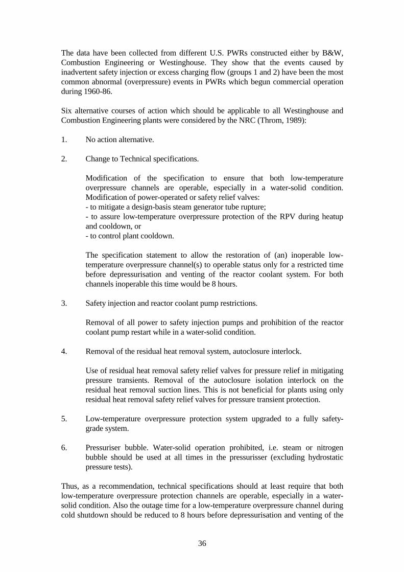
The data have been collected from different U.S. PWRs constructed either by B&W,Combustion Engineering or Westinghouse. They show that the events caused byinadvertent safety injection or excess charging flow (groups 1 and 2) have been the mostcommon abnormal (overpressure) events in PWRs which begun commercial operationduring 1960-86.
Six alternative courses of action which should be applicable to all Westinghouse andCombustion Engineering plants were considered by the NRC (Throm, 1989):
1. No action alternative.
2. Change to Technical specifications.
Modification of the specification to ensure that both low-temperatureoverpressure channels are operable, especially in a water-solid condition.Modification of power-operated or safety relief valves:- to mitigate a design-basis steam generator tube rupture;- to assure low-temperature overpressure protection of the RPV during heatupand cooldown, or- to control plant cooldown.
The specification statement to allow the restoration of (an) inoperable low-temperature overpressure channel(s) to operable status only for a restricted timebefore depressurisation and venting of the reactor coolant system. For bothchannels inoperable this time would be 8 hours.
3. Safety injection and reactor coolant pump restrictions.
Removal of all power to safety injection pumps and prohibition of the reactorcoolant pump restart while in a water-solid condition.
4. Removal of the residual heat removal system, autoclosure interlock.
Use of residual heat removal safety relief valves for pressure relief in mitigatingpressure transients. Removal of the autoclosure isolation interlock on theresidual heat removal suction lines. This is not beneficial for plants using onlyresidual heat removal safety relief valves for pressure transient protection.
5. Low-temperature overpressure protection system upgraded to a fully safety-grade system.
6. Pressuriser bubble. Water-solid operation prohibited, i.e. steam or nitrogenbubble should be used at all times in the pressurisser (excluding hydrostaticpressure tests).
Thus, as a recommendation, technical specifications should at least require that bothlow-temperature overpressure protection channels are operable, especially in a water-solid condition. Also the outage time for a low-temperature overpressure channel duringcold shutdown should be reduced to 8 hours before depressurisation and venting of the

37
coolant system. The low-temperature overpressure protection system should hence betreated as a system performing a safety-related function. The results of the value analysisof different alternatives (Throm, 1989) are excluded from this review.
The protection system requirements in Standard Review Plan 5.2.2 specifies both themaximum pressure as a function of temperature, and the enable temperature in the formRTNDT + 32oC. The ASME Code Case N-514 (Dec. 92) requires the maximum pressureto be 110% of the ASME allowable pressure and the enable temperature of RTNDT +10oC (Fig. 22) (Gamble, 1994).
Fig. 22. Operating window associated with a low-temperature overpressure protection(LTOP) system P-T limits (RCP = reactor coolant pump) (Gamble, 1994).
For plant operability, low-temperature overpressure protection means that the timerequired for normal heatup and cooldown stages is increased with increasing neutrondose (as well as RTNDT), i.e. the operating window is narrowed due to aging of the RPV.In addition, there is a risk of LOCA (loss of coolant accident) if certain valves in thelow-temperature overpressure protection system fail to close after actuation (Gamble,1994). Factors reducing the operating window are described in Fig. 23.

38
Fig. 23. Factors reducing the operating window in pressure, when thepressure/temperature (P-T) limit is protected by an overpressure protection (LTOP)system (Gamble, 1994).
3.4 HIGH-TEMPERATURE TRANSIENTS
For high-temperature transients (and operation conditions in general), the RPV materialshould have a sufficient upper-shelf toughness. Measures are required, e.g. by the NRC,when the upper-shelf toughness (CVN) falls below 68 J (Gamble, 1994). Currently,upper shelf energy below 68 J does not appear to be an issue that will require annealingof RPVs (Carter, 1994).

39
4 ANNEALING
4.1 METHODS
The first RPV annealings were realised using primary coolant and nuclear heat (USArmy SM-1A) or pump heat (Belgian BR-3). Annealing temperatures were roughly80°C above the service temperature. The degree of recovery of Charpy-V transitiontemperature in these cases was about 60%. The planned annealing of the Yankee Rowevessel was estimated to give 45-55% recovery at a temperature of 343°C, which is 83°Chigher than the service temperature (Server & Biemiller, 1993).
In the "wet" annealing method the maximum temperature is limited to about 350°C.Hence it can be used only in reactors with a low service temperature. Due to a ratherlimited recovery and a high re-embrittlement rate, wet annealing is not a viable solutionfor power reactors.
In dry annealing the RPVs have been heated by electric resistance heaters. Proposals forusing e.g. induction heating, superheated steam or hot burned gas have also beensuggested.
4.2 ACCOMPLISHED ANNEALINGS
By the spring of 1994, a total of 14 thermal annealings in VVER 440 reactors (plus aprototype annealing for decommissioned Novovoronezh 1- RPV) had been carried out.
Table 7. Annealings of VVER 440-type RPVs.
Reactor Year Temperature/time (°C/h) SS clad
Novovoronezh 3 1987 430±20°C / 150h noArmenia 1 1988 450+50°C / 150h noGreifswald 1 1988 475-10°C / 150h noKola 1 1989 475°C / 150h noKola 2 1989 475°C / 150h noKozloduy 1 1989 475°C noKozloduy 3 1989 475°C yesGreifswald 2 1990 475-10°C / 150h noGreifswald 3 1990 475°C yesNovovoronezh 3 (re-ann.) 1991 475±15°C / 100h noNovovoronezh 4 1992 475°C / 150h noKozloduy 2 1992 475°C / 150h noJ. Bohunice V-1/2 1993 475-503°C / 160h yesJ. Bohunice V-1/1 1993 475-496°C / 168h yes

40
Because the embrittlement of base metal, due to low Cu and P contents, has been foundto be sufficiently small, heat treatments of all the RPVs above have been focused onlyon one circumferential weld seam in the core zone, as seen in Fig. 24. The secondpotentially embrittling weld is situated above the core and receives only about 1% of themaximum neutron exposure. During normal reactor lifetime the transition temperatureof it is not expected to rise higher than to about 100°C. Hence it is possible to use arather narrow heating zone. The width of the peak temperature zone was approximately1.5 m or less. The temperature on the outer surface of the critical weld was about 20°Clower than on the inside, its value depending on the cooling conditions there (e.g.insulations and air flowing).
One of the most critical points in annealing is to keep thermal stresses within acceptablelimits. In the dry annealings done so far, this has been calculated to be possible whenheatup and cooldown rates do not exceed 20°C/h and 30°C/h, respectively. Temperaturelimits for the surrounding structures seemed not to be a critical issue.
Fig. 24. The annealing arrangements in Novovoronezh 3 (Cole&Friderichs, 1991).

41
In many reactors, actual archive material from the RPV or surveillance test programmeshas not been available, rendering the exact degree of embrittlement unclear. For thisreason it has been most important to perform material testing, e.g. chemical analysis andtoughness tests, with samples cut from the pressure vessel itself. In old VVER 440reactors the lack of stainless steel cladding makes this possible from the inner surface,too. Boat samples of about 5-8 mm depth with other dimensions of few centimetreshave been taken. The samples have been used to prepare subsize impact specimens forevaluating the toughness before and after annealing. Additionally, milling chips forchemical analysis have been removed. In cladded RPVs, removal of material has alsobeen performed. The gap between the outer vessel surface and the biological shield tankin the reactor cavity is sometimes only a few centimetres, making the removal of boatsamples or chips, as well as hardness measurement, rather troublesome. Unfortunately,in many VVER 440 reactors the surface layers of the weldment have been welded withan unalloyed filler material, which prevents representative sampling of the actual weldmetal. In these cases the actual weld metal cannot be obtained, as the needed samplingdepth is too large requiring repair welding after sampling.
In many old western RPVs the situation is far more complex; they usually have axialweld seams, meaning that the entire core zone requires thermal treatment. This makes itdifficult to avoid unacceptable high stresses and residual strains in the nozzle regions(Mager & Rishel, 1982 and Server, 1985). The axial temperature gradient in the vesselmay produce a "coke bottle" shape and bends the primary piping at the vessel nozzles.These problems seem not yet to have been resolved for all types of vessel constructions.
In addition to present guides and rules for thermal annealings (e.g. ASTM E 509,10CFR Part 50 Appendix G & H), new regulatory documents are being developed. ARegulatory Guide on "Form and content for thermal annealing RPVs" (Draft Guide 1-027) and a rule on thermal annealing (anticipated to be 10CFR 50.66) are now underpreparation and due to be completed in 1994.
4.3 RECOVERY AND RE-EMBRITTLEMENT OF WESTERN RPVSTEELS
Irradiation embrittlement in western reactors is mainly due to high Cu content. Becauseolder RPVs are usually constructed of hot-rolled plates, they also have axial joints and,consequently weld metal in the entire reactor core area. As to avoid thermal stresses inannealing, annealing temperatures studied have been chosen to be as low as possible.The majority of test results come from 400°C annealing, which seems to be inadequatefor high Cu welds. Fig. 25 shows recoveries in the transition temperature achieved with400°C and 455°C post-irradiation heat treatments. The fluence was 1.4x10¹⁹ n/cm2. Thedegree of recovery depends strongly on the Cu content. Ni and P have reduced onlyslightly the recovery. The influence of impurities is similar in both base and weld metals(Mager, 1983; Hawthorne, 1989a-b and Hawthorne & Hiser, 1990).

42
Fig. 25a. Notch ductility changes for various welds after irradiation (288°C) and post-irradiation annealing. P = 0.010 - 0.014%; F = 1.4x10¹⁹n/cm2 (≥ 1 MeV) (Hawthorne,1989a).

43
Fig. 25b. Charpy-V transition temperature changes for SA 533 B plates with 288°Cirradiation (left-hand bars) and with 399°C post-irradiation annealing (right-handbars). F ≈ 2.5x10¹⁹ n/cm2 (≥ 1 MeV) (Hawthorne, 1989b).
Charpy-V notch upper shelf energy recovers better than other properties (Fig. 26). Thedegree of recovery measured by fracture toughness is far smaller (Mager, 1983 andHawthorne & Hiser, 1990). As seen in Fig. 26, the degree of recovery in ductile JIc maybe less than half the value in Charpy. No explanation has been given for this behaviour,despite of its importance for the evaluation of RPV integrity. The Heavy-Section SteelIrradiation (HSSI) Program, where irradiated, annealed and reirradiated fracturetoughness specimens up to 4 inches in size will be tested, will give more clarification(USNRC, 1991 and Corwin, 1992).

44
Cu contents: EP-19: 0.40%EP-23: 0.23%EP-24: 0.35%
Fig. 26. Comparison of recovery annealing results for different welds (Ni = 0.59%)(Mager, 1983).
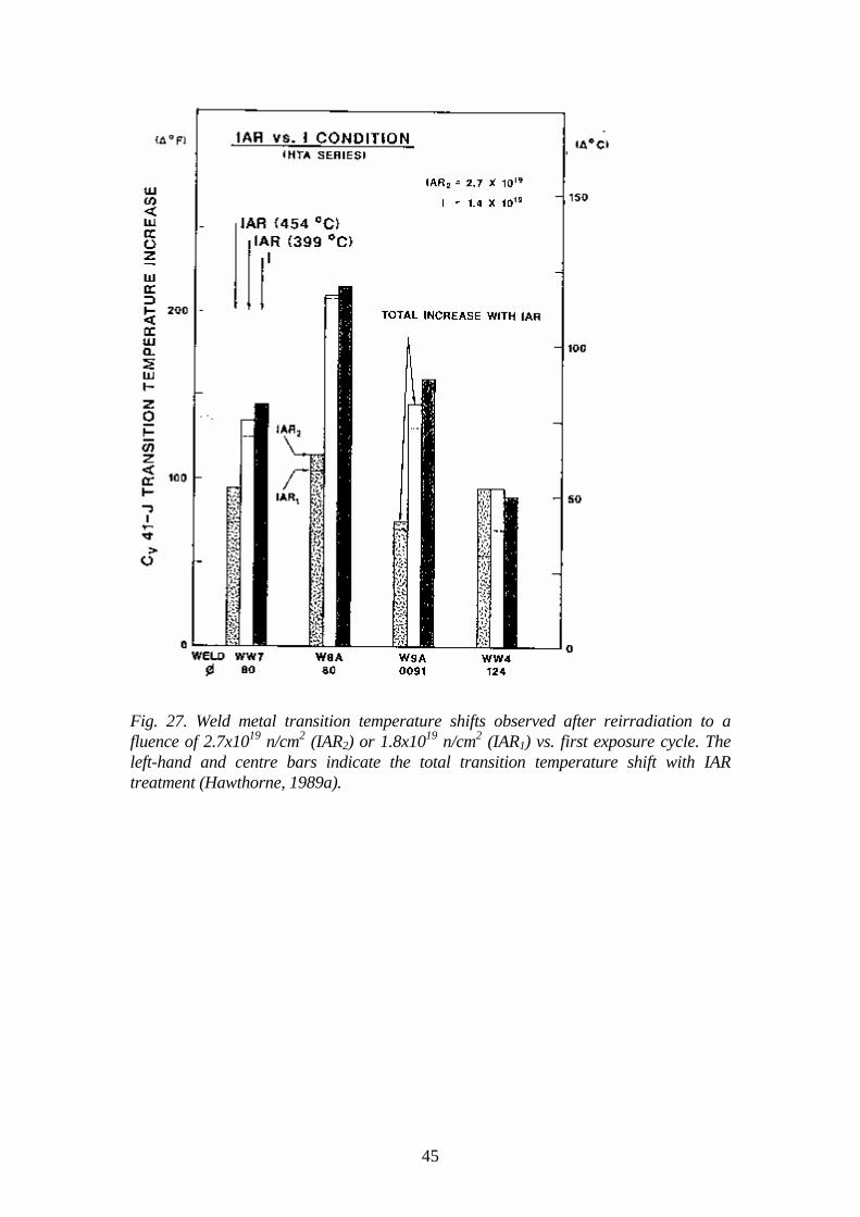
The re-embrittlement rate after recovery anneal is usually equal to or smaller than thatobserved in the first irradiation. A high annealing temperature is more favourable in thisrespect. Results for welds with various Cu and Ni contents are shown in Figs. 27 - 28.
45
Fig. 27. Weld metal transition temperature shifts observed after reirradiation to afluence of 2.7x10¹⁹ n/cm2 (IAR2) or 1.8x10¹⁹ n/cm2 (IAR1) vs. first exposure cycle. Theleft-hand and centre bars indicate the total transition temperature shift with IARtreatment (Hawthorne, 1989a).

46
Fig. 28. Effect of re-irradiation after various anneals on the Charpy-V transitiontemperature shift of weld EP-19 (Cu = 0.40%; Ni = 0.59%) (Mager, 1990).
The annealing process may also have detrimental effects on fracture toughness. In thecase of fine grained base metal, the influence of thermal ageing will not be large (Druceet al., 1985 and Pelli & Forstén, 1987) unless the P content is high. In coarse grainedheat affected zone (HAZ) the situation is different, already a fairly low P content may inthermal ageing increase the ductile-brittle transition temperature by e.g. 35°C when agedat 450°C for 100 hours (Druce et al., 1985), or by 210°C when annealed at 450°C for2000 hours (McElroy, 1992). Fortunately the preirradiation ductility of HAZ is usuallyclearly higher than in the normal base metal, which gives a greater margin forembrittlement (Fig. 29).

47
Fig. 29. Comparison of Charpy transition curves for unirradiated, irradiated, post-irradiation annealed (475°C/168h) and unirradiated thermally aged (450°C/ 2000 h)material in the simulated (1200°C/0.5 h + stress relieving heat treatment) coarsegrained HAZ condition (McElroy, 1992).
4.4 RECOVERY AND RE-EMBRITTLEMENT OF VVER 440 RPVs
High P and fairly high Cu contents in weldments have caused a serious radiationembrittlement problem in many VVER 440-type RPVs, resulting in 14 annealings todate. Problems with the base material have not been reported. The first in-serviceannealing was made at 430°C (about 165°C above the irradiation temperature), whichwas later found to be too low for adequate recovery; nowadays 475°C is typically used.In Bohunice it was chosen 475°C for the minimum temperature on the outer surface ofweld seam, when due to the temperature gradient the inner surface reached about 500°C.Some results from investigations done with base and weld materials irradiated inresearch or commercial power reactors are shown in Figs. 30 and 31. The irradiationtemperatures also in test reactors were aimed to be equal to power reactors, but due todifficulties in temperature control, rather large differences can exist.

48
Symbols: ∆ ! base metal" # weld metal + Novovoronezh 1 weld metal∆ " irradiated in research reactor#! irradiated in VVER 440
Fig. 30. Effect of the difference between annealing and irradiation temperatures on therecovery of Charpy-V transition temperature in VVER 440 RPV steels (Amayev et al.,1990).

49
Fig. 31. Effect of fluence rate and difference between annealing and irradiationtemperatures on the recovery of transition temperature TK in VVER 440 RPV steels(Ignatov et al., 1990).
a) irradiated in research reactor VVR-Mb) irradiated in VVER 440φ: ⊕ , ⊗ , +,x ≈ 3x10¹⁶ n/m2s #, ◊ ≈ 3x10¹⁵ n/m2s $ ≈ 5x10¹⁴ n/m2s
The results suggest that the lower boundary of the recovery percentage in annealing at475°C is about 80%. There is some evidence that after low fluence rate (e.g. RPV wall)recovery may be retarded. The P content has a marked effect on residual embrittlement.A high annealing temperature is needed especially with high P contents (Fig. 32). Clearevidence of thermal ageing during recovery annealing cannot be found in the literature,but coarse grained HAZ has not been adequately investigated. In Bohunice reactors theannealing temperature on inner surface was about 500°C, of which higher than used instudies.

50
Fig. 32. Effect of P content and annealing temperature on the residual embrittlement ofVVER 440 steels (Amayev et al., 1993a).
The investigations show that the re-embrittlement rate does not usually exceed theembrittlement rate in the first irradiation. Data for VVER 440 RPV steels after variousirradiations and heat treatments are shown in Figs. 33-36.
Fig. 33. Transition temperature shifts (Charpy-V) of VVER 440 RPV base metal (P =0.020%; Cu = 0.11%) in irradiation in VVER 440 reactor and in thermal annealing(Amayev et al., 1993b).

51
Fig. 34. Transition temperature shifts (Charpy-V) of VVER 440 RPV base metal insurveillance irradiation and in thermal annealing (IAEA-TECDOC-659, 1992).
Fig. 35. Transition temperature shifts (Charpy-V) of VVER 440 RPV weld metal (P =0.023%; Cu = 0.12%) in surveillance irradiation and in thermal annealing (Amayev etal., 1993b).

52
Fig. 36. Transition temperature shifts (Charpy-V) of VVER 440 RPV weld metal (P =0.028%; Cu = 0.18%) in surveillance irradiation and in thermal annealing (IAEA-TECDOC-659, 1992).
5 OTHER MITIGATION METHODS
5.1 PRESTRESSING
Prestressing of the RPV has been suggested as a potential method for preventing PTSfailures (Ayres & Barishpolsky, 1993 and Ayres & Siege1, 1994b). The stresses duringpostulated PTS events are lowered in this method by prestressing the RPVmechanically, e.g. with a memory alloy band wound on the outside surface.
The predictions made for postulated (and somewhat simplified) PTS events and RPVshave shown that an increase in the RPV temperature margin due to prestressing couldallow a significant service life extension without exceeding the embrittlement criterion(Ayres & Barishpolsky, 1993). One prediction has been made for an RPV with thefollowing dimensions:
inside radius 218 cmwall thickness 216 mmcladding 6.4 mmactive core height 483 cmtotal RPV height 1245 cm

53
The RPV material was an SA533 B Class 1 plate with RTPTS = 143oC (thus exceedingthe NRC screening criterion of 132oC for axial welds). Only an axial weld (and crack)was considered. Prestressing was assumed to affect the stresses only in the hoopdirection. The prestress was induced by 100 mm thick rings placed on the beltline regionof the RPV so as to cover most of the core region. The heat transfer and elasticproperties of the band were assumed to be identical to those of the RPV. The yieldstrength of the band was 483 MPa at 20oC and 420 MPa at 316oC. The resulting hoopprestress of 221 MPa was computed to induce a prestress of 104 MPa in the RPV. Thepressure in the postulated PTS was assumed to drop quickly from a normal operationlevel to 6.9 MPa and remain constant.
The stress intensity factor (KI) for a 25 mm crack (in base material) with and without theprestress, and the KIc curve for the RPV material are shown in Fig. 37. The resultsdemonstrate that an increase in the temperature margin of at least 17oC (30oF) can beachieved with prestressing. For a 50 mm crack this margin was 28oC, which suggeststhat greater margins could be obtained if the analyses were based on crack arrest.
Fig. 37. KI vs. temperature during a PTS transient (25 mm crack) with and without theprestress band (Ayres & Siegel, 1994b).
The 17oC increase in thermal margin allows up to 30 years of additional service life in ahypothetical case as shown, for example, in Fig. 38 (Ayres & Barishpolsky, 1993).

54
Fig. 38. Effect of a 17oC increase in thermal margin on the service life of a hypotheticalRPV. The RT curve is based on NRC Reg. Guide 1.99 Rev. 2 (Ayres & Barishpolsky,1993).
It has been shown (Svärdh & Kornfeldt, 1994) that a uniformly distributed external loadon the RPV could induce a negative stress intensity factor at the location of the assumedcritical circumferential weld for all realistic crack depths (due to prestress only), whenthe distance between the weld and the midplane of the prestress area has been adjustedto induce the maximum compressive stress at the weld location (assuming a semi-elliptical circumferential crack with depth-length ratio 0.1 on the inside surface and nocladding). An external pressure load of 26 MPa induced the maximum (axial)compressive stress of 100 MPa on the inside when only the other side of the weld wasloaded (RPV dimensions: inner diameter 3800 mm, wall thickness 140 mm, length ofloading segment 800 mm). In longitudinal welds circumferential tensile stresses arereduced by the membrane stress instead of bending stresses.
Different technical solutions to create the required prestress in the RPV have beenpresented (Kornfeldt et al., 1993 and Ayres & Siegel, 1994b). A memory alloy wire can,for example, be wound around a sectioned ring tool, which serves as a substrate for thecontracting memory material. The dimensions of this ring and the number of turns of thewire can be determined according to the magnitude and direction of the requiredcompressing force. The ring (or rings) would then be placed in the proper location onthe RPV relative to the critical weld (Fig. 39). In the version where two rings areconnected with bars, these contribute to the axial prestress. The compressive prestress iscreated at the operating temperature of the RPV, when the memory material shrinks dueto phase transformation.

55
Fig. 39. Prestressing of circumferential weld using memory alloy ring(s) and a ringinstalled on a RPV (Kornfeldt et al., 1993).
A technique based on the use of spring-loaded bands is presented in Fig. 40. Rings areinstalled by lifting them one at a time to a proper position as shown in Fig. 40.
In general, an advantage of prestressing is that it provides a mechanical method whichcan be applied with high precision to give optimised results. In addition, the effect ofprestress can be measured and the effect ensured by keeping the prestress tool installedon the vessel. More data are needed e.g. on access to the RPV periphery and design ofthe prestress tool to minimise unfavourable tensile stresses (Kornfeldt & Österlund,1994).
It is evident that the proposed prestressing significantly alters the stress and temperaturedistributions in the RPV, not only during PTS events but also under cooldown andheatup stages. These give good reason for a comprehensive plant-specific evaluation,including at least analyses of different transients for each RPV type, tensile stresses onthe inside surface of the RPV during the cooldown stage, and the tensile stress peak inthe RPV near the border of the band and RPV contact region.

56
Fig. 40. Construction of a prestress band and installation of bands on an RPV (Ayres &Siegel, 1994b).
Also to be examined are the long-term thermal properties of the band material andpossible changes in properties (especially the memory effect) due to irradiation, as wellas the behaviour of the band during different transients. The problem of how todetermine the prestress should also be resolved. It should be noted that so far theapplicability of the method for a RPV has not been demonstrated.

57
5.2 WARM PRESTRESSING
Warm prestressing, i.e. overloading below the KIc of the material at a temperature higherthan service temperature, has been suggested to be applicable for raising the fracturetoughness of RPVs (Pokrovsky et al., 1994). This method would provide a means toavoid possible thermal embrittlement associated with annealing. The composition (highimpurity contents) of the steel would also not restrict the applicability.
No detailed procedure of performing warm prestressing for a RPV has been published.One major question would evidently be how to load the RPV so that the desiredprestress will be achieved. Compared with annealing, a great advantage would be thatwarm prestressing can be performed at lower temperature, for example at the normaloperating temperature of a RPV.
Theories of warm prestressing have been developed and applied in analysingconsequences of PTS transients even years ago (Bryan et al., 1987 and Russian standardM-PTN-01-94, 1994), but only in Russian publications the phenomenon has beenpresented to be applicable for raising the fracture toughness of RPVs.
5.3 WELD REPLACEMENT
For RPVs where embrittlement is markedly faster in the weld area than in the basematerial (as is usually the case), service life extension might be possible so that the mostembrittled material is removed and replaced with more resistant material (Server et al.,1993). No descriptions of techniques for performing the weld replacement wereavailable for this work.
5.4 REPLACEMENT OF THE RPV
This alternative would be very expensive for most PWRs since the RPVs andcontainment buildings were not designed for replacement. Therefore the measure wouldrequire significant destruction of concrete walls and of the containment, possibly alsothe refuelling pool. A concern would also be disposal of the old RPV. This alternativehas not been investigated extensively by the industry, but an assessment on the technicalobstacles was performed in the early 1980s (Server et al., 1993).
On the other hand, it has been estimated that replacement of a RPV would cost "only"$50 - 80 million which is even less than the cost of replacement of a steam generator($50 - 300 million) (Joosten & Godin, 1993).
5.5 POWER REDUCTION
The fluence rate at the RPV can also be decreased simply by reducing core power. A 10- 20% power reduction has typically been projected to result in sufficient reduction inthe fluence rate (Server et al., 1993). There are no reported cases in which only deratingwould have been used to decrease the fluence rate.

58
6 APPLICATIONS AT SOME NUCLEAR POWERPLANTSImplemented or planned measures to reduce the fluence rate at some West-Europeanand U.S. nuclear power plants since 1970 are summarised in Table 8 and discussed inmore detail below.
Table 8. Fluence rate reduction measures (implemented or intended) at some West-European and U.S. NPPs.
Plant/reactor/core crit.RPV
welds
Measure forflux. red 1)
Flux reduction(factor or %)
Time ofimpl.
(yr./cycle)
Ref.
KWO/Obrigheim360 MWe/121 ass.
circ. LL(in-in-out)
30-40% 1974 Leitz & K.,1989;Franklin &Marston,1983
" " 12 DA 10 (total) 1978/c. 10 "
Stade/670 MWe/157 ass.
" LL (12 ass.) ca. 2 1977/c. 5 "
" LL+12 AA 4 (total) c. 7 "
Loviisa 1/2VVER 440/349 ass.
" 36 DA 2.82) 1980 c.3/1 Ahlstrand etal., 1991;Franklin &Marston,1983
Point Beach LL 1.5-2.0 - Moylan &Balkey,1987
" LL + Hf abs. ? - "
" LL + SSrods
? - "
St. Lucie 1/217 ass. 16 Hf-ass. 20 yr. life ext. - Twitchell,1991
Maine Yankee/855MWe/217 ass.
long. LL 1.5 c. 7 Jones, 1989
PSE&G/Salem 1/1100 MWe
long. LL (8 ass.) 50 % c. 6 Perrin, 1993
1) LL = low-leakage, DA = dummy assemblies, AA = absorber rods inserted, SS = stainless steel2) At the new critical location

59
Both low-leakage fuel management schemes and dummy assemblies have been appliedto reduce the fluence rate in old KWU plants (Leitz & Koban, 1989). At a 360 MWepower plant (probably the Obrigheim plant) with 121 fuel assembly core, the water gapbetween the core and the RPV was originally small and hence the neutron fluence rate atthe RPV high (EoL fluence 7x1019 cm-2) (Franklin & Marston, 1983 and Leitz & Koban,1989). A local fluence rate reduction factor of 10 was achieved (compared to theoriginal OUT-IN scheme) when 12 fuel assemblies were replaced after the ninthoperating cycle by stainless steel dummy assemblies. (In addition, a change from OUT-IN to IN-OUT scheme had been performed after five operating cycles.) The EoL fluenceafter these operations was reduced to 3x1019cm-2. The fluence rate reduction waspossible without power reduction.
A KWU 670 MWe power plant (probably the Stade plant) with 157 fuel assembly corealso suffered from a high local fluence rate at the RPV (Franklin & Marston, 1983 andLeitz & Koban, 1989). The original EoL fluence of 4x1019 cm-2 could be reduced to2x1019 cm-2 by replacing 12 peripheral fuel assemblies with partially burn-up fuelassemblies after five operating cycles and later (after the seventh operating cycle) byinserting absorber rods into the replaced assembly positions. The total fluence ratereduction factor after these measures was 4. Also in this case power reduction wasavoided.
At the Public Service Electric & Gas 1100 MWe power plant (RPV manufactured byCE) in the U.S.A., 18 years extension in the service life of the RPV could be achieved(corresponding to EoL fluence 2x1019 cm-2) by replacing eight corner fuel assemblieswith exposed ones (Perrin, 1993). The local fluence rate reduction factor of 2 (50%) wasachieved using this low-leakage scheme.
At the Maine Yankee 855 MWe power plant (217 fuel assembly core, RPVmanufactured by CE) in the U.S.A., the OUT-IN scheme was replaced with a low-leakage scheme, where one and two cycles exposed fuel assemblies were loaded at thecore periphery after six operating cycles in 1980 (Jones, 1989). As a result the fluence atexpiration of license was reduced by 33%.
Several fuel management schemes were studied using the 450 MWe WestinghousePWR in operation since 1968 at San Onofre in the U.S.A. as a representative unit(Fenech, 1985). The aim was to minimise the fluence at the three longitudinal welds inorder to extend the current 28 EFPY vessel lifetime, corresponding to an EoL fluence of23x1019 n/cm2. From the two examined low-leakage fuel schemes and one low-leakage + dummy stainless steel assemblies scheme, a low-leakage scheme with 4%235U enrichment fuel proved to be the most favourable. Using this scheme the vessellifetime could be increased by 6.8 to 34.8 years, and the increase in total electric outputfrom the current cycle to the end was shown to be 5.93%. Power reducing could not beavoided in all three cases despite the use of assemblies containing 12-16 burnable boronpins per assembly (in one reload sub-batch).
Several possibilities were examined for extending the service life of the RPVs of PointBeach Units 1 and 2 by 20 years beyond the licensed 40 years (Moylan & Balkey,1987). It turned out that the required fluence rate reduction factor of 1.5 to 2.0 for thecritical weld locations could be achieved with current fuel design and internals

60
technology. Three fuel management schemes were selected from 14 techniques (listedwith increasing cost and fluence rate reduction effect):
- Low-leakage loading pattern (L4P).- L4P + Hf absorbers in the guide tubes of peripheral assemblies.- L4P + stainless steel rods in place of fuel rods on the outboard side of the selected
peripheral assemblies.
Also examined were various internals design concepts (Schwirian et al., 1986):
- A radial neutron reflector placed between the core baffle plates and the core barrel.- A neutron shield panel bolted to the core barrel.- A combination of these two options.
A 60 year operating life was also pursued by the Florida Power & Light Company forthe St. Lucie Unit 1 in the U.S.A. (Twitchell, 1991). In the first stage (in cycle 10), thefluence rate at the critical RPV weld was reduced by placing eight assemblies with highburn-up on the core periphery. With this measure an additional power reduction of 18%,giving a 4 year life extension, could be achieved at the critical location by comparisonwith the low-leakage scheme applied earlier. For achieving the designed 20 year lifeextension it was necessary to implement further measures. The analysed techniqueswere based on the use of fluence reduction assemblies, i.e. those containing Hf, Gdand/or stainless steel, near the critical welds. The assembly design containing 0.3 wt%235U with Hf inserts in the four guide tubes was selected, and totally 16 fuel assemblieswere replaced on the core periphery by these Hf assemblies (Fig. 41). The replacementwas to be performed in two stages so that eight assemblies were replaced at a time. Thetotal increase in power peaking was 0.05.
Totally 23 options were evaluated to achieve the desired plant life extension. Thefollowing limitations were placed on any acceptable method:
- Low fuel cycle cost- Low impact on safety parameters- Very little or no operations impact- Use of normal reactor materials.
Due to the insertion of Hf-assemblies, the fuel cycle cost increase was 3 - 5% over theremaining life of the plant, which was evaluated to be much less than the cost of RPVmodifications when all costs are considered (Rowan et al., 1993).

61
Fig. 41. Low-fluence scheme applied for life extension of the St. Lucie unit (Rowan etal., 1993).
The pressure vessel of the H. B. Robinson reactor (157 assembly core, 2300 MWt,started in 1971) in the U.S.A. has both longitudinal and circumferential welds (Williamset al., 1990) as shown in Fig. 42. In 1982, fluence rate reduction measures were said tobe necessary for achieving the design service life of the RPV. The two circumferentialwelds in the beltline area were regarded as the most limiting due to the high Cu and Nicontents of the weld material. The first step comprised a transfer to low-leakage loadingmanagement, which reduced the fluence rate at the RPV by a factor of two. The fluencerate peak at the critical circumferential weld could be lowered further by about 75%when 12 fuel assemblies were replaced in the second stage by part-length shieldassemblies on the core periphery (Fig. 42; compare also Fig. 10). These so-called PLSAelements consist of a lower portion with stainless steel rods, a fuel portion in the middle,and an upper portion with rods containing natural U instead of enriched UO2. Hence alarge fluence rate reduction was achieved at the lower weld, whereas the lower fuelpower density near the upper weld assured that this weld would not become a limitingone. The low-leakage fuel management programme was begun during cycle 9. ThePLSA elements were introduced beginning with cycle 10 in 1985, and were to bestandard procedure for the entire remainder of the service life.

62
Fig. 42. The core of H. B. Robinson Unit 2, location of welds and nozzles (top fig.), anddimensions and locations of the part length shield assemblies (PLSA) used to reducefluence rate at the circumferential welds of the intermediate shell (Williams et al.,1990).
Trino Vercellese is an Italian 870 MWt (120 fuel assembly locations) Westinghousetype PWR started in 1964 (Franklin & Marston, 1983 and Buono et al., 1987). At anearly stage of operation the thermal shield installed between the core and the RPV had tobe removed due to vibration caused by the coolant water. To diminish the consequentincrease in the neutron fluence rate at the RPV, eight corner fuel assemblies werereplaced with dummy assemblies, which contained stainless steel pellets instead of UO2.In addition, in 1979 the emergency core cooling system of the plant was totally renewedto meet the requirements for normal and accident conditions, e.g. new low- and high-pressure safety injection systems, a high-pressure accumulator injection system, andcontainment recirculation, spraying and cooling systems were installed. Later a lowtemperature overpressure protection system was installed and the borated watertemperature increased to 60oC both in the accumulators and in the refuelling water

63
storage tanks. Planned maintenance procedures included e.g. replacement of severalsafety-related valves. A corresponding replacement of fuel assemblies was alsoperformed in the French-Belgian Sena PWR, which is of the same type as TrinoVercellese.
At the Loviisa NPP in Finland (VVER 440, 349 assembly positions) the firstsurveillance test results revealed unexpected fast embrittlement on the circumferentialweld. Neutron flux was reduced by replacing 36 peripheral fuel assemblies (roughly10% of the core) with dummy stainless steel assemblies in 1980 after 3 years (Lo1) and1 year (Lo2) of operation (Fig. 43). Due to exceptionally large margins this could beperformed without reducing power, even though the number of replaced assemblies waslarge (Franklin & Marston, 1983 and Ahlstrand et al., 1991).
a b
Fig. 43. Positions of dummy elements (a) and neutron fluence in the maincircumferential directions (b) at the Loviisa NPP (Ahlstrand, 1990).
In addition, the temperature of the emergency core cooling water was raised inaccumulators first to 60oC and later to 100oC, and in the tank first to 45oC and later to55oC (Ahlstrand, 1990). The effect of these measures on the calculated stress intensity ina postulated emergency core cooling event is shown in Fig. 44.

64
Fig. 44. Effect of emergency core cooling water temperature on stress intensity(Ahlstrand, 1990).
Further modifications were performed during 1983 - 86 as follows (Ahlstrand, 1990):
- Decreasing the high-pressure safety injection flow.- Reducing the head of the high-pressure safety injection pumps to avoid opening of
the pressuriser safety valves in some PTS transients.- Increasing the pressuriser relief valve capacity to avoid opening of the safety valve
in some PTS transients.- Introduction of a protection signal at high primary system pressure to stop the high-
pressure pumps connected to the primary circuit.- Modification of protection signals associated with occurrence of a steam line
break.
In VVER 440/230 -type reactors, excessive embrittlement is mainly due to a smallwater gap between the fuel and the RPV, and to high impurity contents of the weldmaterial. When the first surveillance tests showed higher than expected transitiontemperatures, several remedial measures were proposed as follows (IAEA-TECDOC-659, 1992):
- Modification of operation pressure-temperature limits.- Low-leakage fuel management and core reduction using dummy assemblies.- Temperature increase in the emergency cooling tanks.- Replacement of injection pipes from the cold to the hot leg of the main circulation
loop and installation of fast-closing valves in the main steam system.- Recovery annealing.
The following measures for RPV life extension (VVER 440/230) have also beenmentioned (Dragunov, 1994):

65
- Introduction of additional interlocks.- Change of hydrotest temperature.
Measures implemented at some VVER 440/230 power plants are summarised in Table9.
At the Jaslovske Bohunice power plants in the Czech Republic (four VVER 440/230reactors in two units), measures which have been or are to be implemented are asfollows (Brumovský et al., 1991):
- Emergency coolant temperature increase from 20oC to around 55oC.- Placement of 36 dummy assemblies on the core periphery.- Installation of quick operating valves and a pressure-temperature limiter.- Recovery annealing of the RPV.
The effect of fluence rate reduction measures and annealing treatments on the calculatedcritical RPV brittleness temperature (Tk) for the base material (BM) and weld (WM) oftwo RPVs (V1/1 and V1/2) is shown in Fig. 45. The value of Tk is determined by theimpurity contents (only weld material) and neutron fluence for both weld and basematerials. Due to the core reduction performed in 1985 and the annealing treatment in1992, the allowable critical temperature of brittleness (Tk
a) for a defect size of 16 mm(181oC) is not expected to be exceeded in the RPV of V1/2 until the year 2002. In V1/1dummy elements were to be inserted in 1992. (Actually in V1/1 dummy elements wereinserted in 1991 and both RPVs were annealed in 1993 (KupØca et al., 1994).)

66

67
Fig. 45. Fluence rate reduction and recovery annealing scheme for two RPVs (V1/1 andV1/2) of the Jaslovske Bohunice power plant. Curves "WM" are for welds and curves"BM" for base materials at two circumferential locations (Brumovský et al., 1991).
The effect of dummy assemblies on the circumferential fluence rate distribution in theRPV is shown in Fig. 46 (Bohunice Unit 1).
Fig. 46. Fluence rate distribution in the RPV of Bohunice Unit 1 with and withoutdummy assemblies (KupØca et al., 1994).

68
7 EVALUATION OF MITIGATION METHODS INPWRS
Before any evaluation of the existing embrittlement mitigation methods is feasible, thematerial and environmental factors involved in the development of embrittlement shouldbe understood (Fig. 47). These factors, used as the initial data in making decisionsbetween different options, are e.g. the chemical composition of the base and weldmaterials of the RPV, the anticipated EoL fluence, fluence rate, fluence spectrum,fluence distribution in the RPV, and irradiation temperature. The number ofuncertainties is great, especially in cases where irradiation embrittlement is evaluatedsolely according to trend curves based on fluence and the contents of some impurities.Although these curves have in many cases been found to give conservative estimates,the material data consist typically of only certain types of steels (and/or data from testreactors) and are therefore not necessarily valid for predicting the irradiationembrittlement rate of other types of steels. Both under- and overconservative estimatescan be avoided if materials data from plant-specific surveillance programmes are used inpredicting the remaining service life of the RPV. The possible inaccuracy of determiningthe irradiation shift can be avoided if the evaluation is based on the direct fracturetoughness testing with precracked specimens rather than Charpy-V impact tests.Besides, as expressed by Shah et al. (1989), "The magnitude of the technicaluncertainties increase with the length of the projected time frame and may be importantto the issues of license renewal."
A pressurised thermal shock on the RPV inner wall is generally considered to be aprimary safety concern due to irradiation embrittlement. For the oldest plants thedemand to narrow the operating window due to irradiation embrittlement may becomean operating concern, but probably not a primary safety concern. There are also effectiveremedial measures available to prevent low temperature overpressure transients. Severalmeasures have already been implemented in U.S. plants. Requirements of the uppershelf energy are not believed to be a safety concern or require remedial actions. Thedecrease of upper shelf energy depends, however, strongly on the irradiationtemperature.

69
7.1 APPLICABILITY AND USE OF DIFFERENT METHODS
Fig. 47. Summary of embrittlement mitigation measures and related factors.

70
Once the initial data are available, evaluation and comparison of different mitigationmethods can be done. For example computer codes (discussed in greater detail in thenext section) can be used for comparing the costs and benefits of different options.Although a detailed plant-specific evaluation is always necessary before anyrecommendation on optimum method(s) can be given, some general aspects apply:
- The situation is typically most difficult for old (1960s) and small PWRs, where theembrittlement rate of the RPV is high due to the high fluence rate and/or high impuritycontents. Near the end of the current service life of the RPV, i.e. when the fluence of thematerial is high and fluence rate reduction thus ineffective, final plant shutdown cannotbe ruled out as an option when comparing different solutions. In certain cases annealingtreatment would evidently be the best and perhaps the only feasible possibility to extendthe service life.
- After a long operating time (10 EFPY according to Gerard, 1990) fluence ratereduction becomes less effective, reducing the number of available potential mitigationmethods. However, core reduction using full or part length shield assemblies can beused to achieve a large local reduction in neutron fluence rate. For small cores the use ofdummy assemblies may significantly decrease the thermal margin and/or increase fuelcosts if core power is not reduced.
- The user must be assured in advance that the requirements for license renewal will bemet after the intended annealing. For example, a full-scale demonstration may becomenecessary to ensure that the structural integrity of the vessel is maintained (Burke et al.,1993). It must be emphasised that methods based on fluence rate reduction are notusable at later stages of the plant life history (Dragonajtys et al., 1991).
- Preparatory measures for possible annealing treatment must be taken well in advance.This is worth noting even where some other embrittlement mitigation strategy is chosen.For example, surveillance programmes should be modified in time to include alsoannealed specimens for obtaining experimental data on the re-embrittlement rate of theRPV material.
Hence, for evaluating different mitigation methods RPVs can be divided roughly intothree groups according to the fluence at the time of the intended implementation:
- Old RPVs (1960-70) which after exposure to a high irradiation fluence are nearthe end of their service life. In such cases service life can be extended effectivelyonly by annealing the RPV, and/or by applying some other method(s), for examplemodifications of emergency core cooling systems or possibly prestressing.
- Middle-aged RPVs (1980s) with operation time less than 10-15 years. Significantcore modification/reduction and/or shielding (internals modification). Annealingcan be considered either as an alternative or as a supplementary method.
- New RPVs (late 1980s or later). Irradiation embrittlement of the RPV is notexpected to limit plant lifetime.

71
Low-leakage fuel management schemes have to date been primary procedures forreducing the fluence rate at the RPV. In general, any low-leakage fuel managementscheme would likely be an advantageous option for utilities, if this could be donewithout significantly increasing (or decreasing) the fuel cycle cost and without the needto reduce power. It is expected that during 1994 most PWRs will follow some kind oflow-leakage fuel management. The new fuel designs have evidently enhanced this trend.The major problem for utilities is probably finding the optimum loading scheme. Dataon fluence rate, spectrum and distribution are needed for comparing various loadingschemes, which brings up the meaning of neutron transport calculations and neutrondosimetry. The fact that methods of fuel management are becoming less effective due tosaturation of embrittlement suggests that implementation of these measures berecommended, even if some other strategy has been shown to give a somewhat bettervalue/cost ratio, as the number of measures available later in the plant time history canthus be increased and implementation of more costly measures derated.
Economic evaluation is more complex when further fluence rate reduction procedures,such as combinations of low-leakage loading and possibly other method(s), are to beimplemented to extend the RPV service life, as there will usually be a marked increasein the fuel cycle and/or implementation costs. Until now, installation of dummyassemblies has been implemented in a few power plants only.
Because irradiation-induced degradation of mechanical properties, expressed e.g. by theshift in RTNDT as a function of fluence, is very fast at the start of the plant life, therequired fluence rate reduction factor for a given service life increases rapidly the longerthe time before implementation (Fig. 48). Roughly 50% of the expected shift in RTNDToccurs in less than 2 - 2.5 years of operation (Franklin & Marston, 1983).
At any rate, measures to reduce the fluence rate should be implemented as early aspossible. The decision as to the method(s) used should be made after the first or secondfuel cycle, i.e. soon after the first surveillance test results are available (Mager, 1993). Itusually takes 2 to 3 years to complete the change to a low-leakage loading scheme. Theapproximate recommended timing of different mitigation measures is shown in Fig. 49.

72
Fig. 48. Curves for evaluating the effect of different alternatives (Zion Unit 1, limitingcircumferential weld) (Meyer et al., 1990).
In plants where inadequate mixing of the safety injection water and the cold loop wateris attributed to the PTS issue, modification measures to enhance this mixing areevidently an effective way to increase the safety margin. The same is true of raising thetemperature in the injection water tank. Measures for reducing the probability of PTSsor those relieving the pressure increase during PTSs, i.e. development ofinstrumentation, have also been applied in some PWRs.
To summarise, much research has been done by research institutes and utilities on themethods, parameters and effects of different annealing heat treatments. Annealing couldeven provide an effective, although costly, means for extending the RPV service lifeparticularly in cases where available low-leakage loading schemes are useless orinsufficient, if the intended life extension is also for other critical components feasible.Modification of the emergency cooling system and related measures are likely to beregarded as complementary (and to a certain extent obligatory) rather than primarymethods in extending the RPV service life. Hence for many PWRs, especially when asignificant service life extension is desired, an annealing treatment with a reducedfluence rate might become a principal method. On the other hand, even a 20-year lifeextension has been shown to be achievable only by placing special fuel assemblies atcritical locations, as was done in the St. Lucie plant (Twitchell, 1991).

73
Fig. 49. Timing of embrittlement mitigation measures.

74
7.2 STRATEGIES AND METHODS FOR MANAGING IRRADIATIONEMBRITTLEMENT
The objectives and methods of reducing the fluence rate at RPVs have been somewhatdifferent in the U.S.A. and Europe. In the U.S.A. the primary objective has previouslybeen to reduce fuel cycle costs, while in Europe it has normally been to reduce thefluence rate at the RPV. In the U.S.A. typical methods have been low-leakage loadingschemes, while in Europe more effective methods, especially dummy assemblies, havealso been used (Franklin & Marston, 1983). For U.S. nuclear plants the extension by 20years of 40-year operating licenses is considered to be technically feasible. The 60-yearservice life is already being pursued by the nuclear utility industry (Perrin, 1993).Different tools have been developed for evaluating and comparing embrittlementmanagement alternatives (Meyer et al., 1990 and Griesbach, 1994). One of the mostrecent decision tools is the VTester-code (Griesbach, 1991; Server et al., 1993 andGriesbach, 1994) and the RPV embrittlement management handbook by EPRI (Carter,1994).
A decision making process for reducing the fluence rate by methods of shielding andfuel management is shown in Fig. 50.
Fig. 50. A fluence rate reduction programme (Meyer et al., 1990).
ESTABLISH FLUXREDUCTION GOALS
FLUX REDUCTION THROUGHFUEL MANAGEMENT
• Develop Criteria for Fuel ManagementEvaluations
• Assess Initial Flux Reduction Benefits& Implementation Difficulty
• Select Maximum of 4 FeasibleOptions for Further Evaluation
• Perform Spatial Calculations toGenerate Power Distributions
• Determine Flux Reduction Factors• Assess Implementation Costs & Fuel
Cycle Costs Effects
FLUX REDUCTION THROUGH INTERNALSMODIFICATIONS OR REPLACEMENT
• Select Modification Schemes & New DesignConcepts
• Review Mechanical & Hydraulic InterfaceCriteria
• Perform Preliminary Neutron TransportCalculations
• Examine Design Criteria, Licensing Issues,Benefits & Costs Associated withModifications & New Designs
EVALUATE ONE PREFERREDMODIFICATION OR DESIGN
• Develop Conceptual Design• Perform Detailed Neutron Transport
Calculation• Evaluate Disposal Considerations• Identify Design Qualification Tasks
IMPLEMENTATION DECISIONS

75
The computer code VTester has been developed to manage irradiation embrittlement ofRPVs and especially the PTS issue. The options are categorised as follows (Server et al.,1993):
- Flux reduction- Fuel management- Shielding- Power reduction
- Gain more information/analysis- Enhanced surveillance programme- Regulatory Guide 1.154 analysis- Material sampling
- Physically alter the material properties- Thermal annealing- RPV weld replacement- RPV replacement
An enhanced surveillance programme option may be required to produce more data onthe irradiation response of critical materials necessary for the PTS issue.
Regulatory Guide 1.154 analysis has been included to show that the likelihood ofthrough-wall crack propagation during a PTS is below the specified value. The analysismay be required when PTS screening criteria are to be exceeded. The guide also givescorrective actions, including fluence rate reduction, operating procedures, trainingprogrammes, in-service inspection, NDT programmes, annealing and plantmodifications.
Material sampling comprises e.g. direct sampling from the base and weld materials fordetermining the exact chemical composition, and possibly the mechanical properties andneutron fluence. Sampling also involves preparation of the surface and in-situ surfaceanalysis using portable equipment to analyse the exposed material (e.g. chemicalanalysis and hardness tests).
In VTester, the plant-specific value analysis of annealing comprises the following(Griesbach, 1994):
- Costs of performing annealing.- Avoided costs of not performing other mitigating measures.- Value of deferring other near-term measures.- Value of improved operating window.- Value of increased RPV service life.
The example evaluations performed by Griesbach (1994) using VTester showed that anyoption (do nothing more, fuel management, shielding and annealing) can be the mosteconomic one depending on the case (e.g. current fluence, fluence rate, RPV materials,core design and screening criteria). Other parameters are price of electric power, interestlevel, costs and availability of special fuels etc. In general, the evaluation is a complexprocedure, and it has been recommended no action be taken before the economic

76
benefits of all available options are assessed (Carter, 1994). The comparison made forone postulated case with VTester is shown in Fig. 51.
The management of RPV failure probability should thus also include measures forreducing uncertainties in the material data and a coherent analysis of PTS events.Besides, plant-specific surveillance programmes are becoming increasingly importantboth in defining the required mitigation measures and in verifying the influence ofimplemented measures. For example, uncertainties about RPV materials properties(particularly the weld and heat-affected zone, from which no specimens had beenincluded in the surveillance programme) contributed markedly to the shutdown of theYankee Rowe plant in 1992 (Server & Griesbach, 1993).
License expiration date 2025Plant capacity 1100 MWCurrent EFPY 6.0 yearsAverage fluence rate 2.17x1010 cm-2s-1
Current fluence 0.5x1019 cm-2
Chemistry factor 108oCInitial RTNDT -49oCScreening criteria limit 132oCCurrent vessel RTNDT 89oCYear screening criteria reached with(no change in strategy) 2018Goal for plant operation 2025
Fig. 51. Transition temperature shift vs. fluence for various mitigation options andcertain core analysed with EPRI's VTester code. In this case, annealing in the year 2018gives the highest value (Griesbach, 1994).

77
7.3 ON RESEARCH NEEDS AND EXPERIENCE
In evaluating the need for research, mitigation measures can be categorised into twogroups as follows:
- The first group includes measures already widely applied in commercial PWRs.Much experience has been gained with low-leakage loading schemes, which have beenused routinely for decades in PWRs. Assuming that consequences of the reducedneutron fluence and licensing of new fuels and loading schemes can be solved, themajor questions for utilities are the economical impacts and perhaps the availability ofspecial fuel types. Emergency core cooling and other safety systems have evidently beenmodified in many PWRs no later than in the early 1980s, when the PTS issue first arose(although there are few documented cases). Reduction of the core and shielding withdummy assemblies are also proven methods.
- The second group includes measures proposed as potential alternatives in extendingRPV service life, but which to date have not been applied in commercial PWRs, or havenot been demonstrated as applicable. Shielding of the RPV using e.g. heavy metalpanels has been presented to make possible fluence rate reduction factors of up to 4, butobviously this method has not been applied. Calculations have suggested thatprestressing of the RPV would be an effective way to reduce stresses in the RPV duringa PTS. The behaviour of the prestress band as well as the RPV itself during pressure andtemperature transients has not been shown. Detailed plant-specific analysis of differentpostulated PTS (and possibly some other emergency) events is thus necessary beforefinal evaluation can be made on the applicability of the proposed prestressingprocedures. Uncertainties are still associated also with the annealing treatments asmentioned previously. For example, problems may be encountered in heat-treatingRPVs with longitudinal welds, as in these vessels the area to be annealed is larger thanin those welded from ring forgings.
It is noteworthy that the process which finally led to the permanent shutdown of theYankee Rowe plant originated simply from a PTS issue. Besides insufficient data on thechemistry and properties of the weld material, several other questions arose both in thearea of thermal hydraulics during a PTS and concerning fracture mechanics analysis, e.g.the density and size distribution of flaws in the vessel. There was even doubt as towhether Regulatory Guide 1.154 was intended to be a conservative or best-estimateanalysis. Also mentioned were the bench-marking of codes, methods of dealing with in-service inspection data in the analysis, appropriate cladding model and credit ofsupplementary surveillance data (Server & Griesbach, 1993). These questions willevidently be clarified in the updated requirements to be issued by the NRC.
Finally, some lessons that can be learned from the Yankee Rowe experience asexpressed by Server & Griesbach (1993) are:
- "If embrittlement of reactor vessels is left unmanaged for too long, or even if a newpiece of detrimental data becomes available for a plant, the technical and regulatoryuncertainties created and the high cost of implementing drastic remedial measures canseverely limit the utility's options for resolving a PTS issue."

78
- The possibility of having a PTS issue should be prevented. An important thing is,however, that "utilities should manage vessel embrittlement rather than trying tomanage the PTS issue".
- "Managing embrittlement must be viewed with the same level of commitment asmanaging degradation in the other major nuclear components."
- "Few people within a utility understand the full range of considerations that come intoplay with managing embrittlement." Important factors are RPV materials, fabricationprocedures, plant design, plant type, fuel loading patterns, operational conditions,regulations and licensing, economics of nuclear plant operation, and cost control andcost planning. Strategic planning techniques are thus useful in evaluating andimplementing embrittlement management strategies.
- "Economical issues cannot be divorced from the technical and regulatory issues."
7.4 RECOMMENDATIONS FOR UTILITIES
The material treated in this review gives rise to the following general requirements:
1. All realistic options should be considered when planning and selecting the strategy toachieve or extend the service life of an RPV. Irradiation embrittlement managementshould be an essential part of plant life management. The use of decision tools likeEPRI's VTester are recommended for managing complex PTS issues.
2. The measures available for reducing the fluence rate at the RPV should be applied asfar as is economically reasonable. Implementation should occur as early as possible inthe plant life history. By reducing the fluence rate the accomplishment of more costlyand complicated measures like annealing can be deferred.
3. Modification of structures to increase mixing of the safety injection water and theloop water should be performed in cases where this mixing is uncertain. Elevation of theinjection water temperature and modification of the safety related instrumentationshould also be examined.
4. Preparatory measures for annealing (e.g. modifications of surveillance programmes)are recommendable, even though some other mitigation method(s) than annealing mayhave been chosen.
5. Uncertainties associated with materials (chemical composition, grain size,microstructure, mechanical properties) and environment (fluence, irradiationtemperature) should be minimised in order to predict correctly the irradiation responseof the properties of base and weld materials. At any rate, results from plant-specificsurveillance programmes are preferred to the use of trend curves alone. When reliabledata on the chemical composition of the base and/or weld materials are not available,irradiation embrittlement should be predicted according to the worst case scenario toensure a conservative result. Updating of surveillance programmes and collectingsamples from the RPV should be considered by the utilities in order to obtain moreaccurate material data.

79
6. Care should be taken that steps to reduce uncertainties and implementation ofembrittlement mitigation measures are not deferred for too long near the expectedattainment of the screening criteria.
7.5 RESEARCH NEEDS
Besides plant-specific evaluations typically carried upon implementation of newembrittlement mitigation measures, general research needs also include:
1. Annealing
- Effects of annealing on different RPV steels, i.e. achievable recovery percentages.- Recovery of the static fracture toughness of different steels.- Recovery of the HAZ areas of welds. Indications of uncomplete recovery of HAZ
areas have been presented.- Recovery of welds and base materials with various impurity contents (e.g. P) at high
annealing temperatures (above 450oC), and embrittlement rates after annealing. Inmany test programmes annealing has been carried out at relatively low temperature. Insome VVER 440 RPVs, maximum annealing temperature has been about 500oC.
- True chemical compositions of weld materials. In some VVER 440 RPVs, forexample, electrodes with different compositions may have been used for welding thesurface and inner parts of welds.
- Control of thermal stresses in RPVs during annealing.
2. Prestressing
- Magnitude of tensile stresses on the inside surface of the RPV during the cooldownstage, and the tensile stress peak in the RPV near the border of the band and RPVcontact region.
- Long-term thermal properties of the band material and possible changes in properties(especially memory effect) due to irradiation, and the behaviour of the band duringdifferent transients.
- A method to determine the prestress.
3. Warm prestressing
- Loading of the RPV to achieve the desired prestress.- Irradiation enhanced strain aging of RPV materials.
Annealing is considered perhaps the most promising mitigation method for embrittledRPVs. Compared to some other methods, annealing is also expected to be preferred bylicenser authorities if material properties can be restored to near the original values withacceptable methods. However, as shown above many questions remain to be solved.Some of these data can be obtained from the surveillance programmes of powerplants. Thus research on the following topics is recommended:
- The need to modify current surveillance programmes to produce data and irradiatedmaterials for studying the effects of annealing.

80
- The need of research and relevant methods to show that desired effects are achievedin RPV welds and base metals through annealing, and that no harmful effects such astemper embrittlement will evolve.
- Improved contents of complementary surveillance programmes to show that re-embrittlement rates are acceptable.
In addition, it is recommended that research within AMES should focus on thefollowing topics: general questions associated with annealing (the list above), andirradiation embrittlement management ensuring that no mitigation methods areoverlooked. A final result of these studies could be general guides for utilities and/ortools for performing evaluations between available options. Attention ought to be paidto the consequences of differences in RPV materials and structures and coreconfigurations.
Replacing the RPV might become a potential mitigation alternative where significantplant life extension is pursued. Technical and economic issues associated withreplacement procedures should therefore also be examined.

81
8 CONCLUSIONS
1. Low-leakage and low-fluence fuel management schemes are commonly used forPWRs to mitigate RPV embrittlement. Special fuel assembly designs have beenprovided by fuel manufacturers to reduce the fluence rate at critical RPV locations withminimum loss of power. Any fluence rate reduction measure(s) should be implementedat a very early stage of the plant history.
2. Fuel assemblies have been replaced with dummies when marked reduction of thefluence rate at the RPV has been required in order to achieve the design service life ofthe RPV. Core reduction, together with modifications in the emergency cooling system,e.g. raising water temperature and/or increasing mixing, has been the normal procedurefor mitigating consequences due to exceptionally fast RPV embrittlement and forextending the service life of VVER 440-type reactors. A few such applications havebeen carried out in western PWRs.
3. Several thermal annealings have been performed in the former Soviet Union, EastGermany and Czechoslovakia, as well as in Bulgaria. According to reports the thermalstress limits have not been exceeded. All of these reactor pressure vessels have had onlyone circumferential weld to be annealed, which greatly simplifies the procedures. Inmany cases the most difficult question has been reliable chemical analysis andassessment of the state of embrittlement. These points are essential for evaluating thedegree of recovery and rate of re-embrittlement.
The annealing treatment of old western RPVs is more difficult, as they usually also haveaxial welds to be treated. Hence the high temperature zone extends close to the thicknozzle course, resulting in high thermal stresses. Detailed plant-specific thermal stressanalysis must be done to verify that the heat treatment procedure is safe for the pressurevessel and piping.
Other open questions are the observed smaller recovery of J-R curves compared withCharpy results, and possible embrittlement due to thermal aging in the coarse grainedHAZ region during annealing.
4. Besides thermal annealing, methods of shielding and prestressing have beendeveloped to decrease the fluence rate at the RPV or stresses during a PTS, respectively.These methods have not been applied in PWRs or their applicability demonstrated.Numerical simulations made for prestressed RPVs have shown that the stress state in thevessel can be significantly lowered. The achievable fluence rate reduction factor usingshielding panels between the core and the RPV has been calculated to be between 1.5and 4, but even a factor of 6.8 has been calculated to be possible using massive neutronreflectors between the core and the RPV.
5. The significance of plant-specific surveillance tests is emphasised. The scope ofsurveillance test programmes for evaluating the effect of implemented annealingtreatments should correspond to those required for original PWRs.

82
6. Irradiation embrittlement management will in many PWRs be raised to a higher levelwithin plant life management as the RPVs become older and approach their safetyscreening criteria. Decision tools have been developed and used for comparingmitigation measures and planning embrittlement management strategies.
ACKNOWLEDGMENTS
The authors wish to acknowledge Dr. Rauno Rintamaa, M.Sc.(Tech.) Matti Valo andProf. Kim Wallin for their suggestions on the manuscript.
REFERENCES
Ahlstrand, R. 1990. Flux reduction and other mitigation measures for RPVs. NEA/CSNIworkshop on the safety assessment of reactor pressure vessels. Espoo, Finland, 8 - 9October 1990. CSNI Report 178. Pp. 451 - 461.
Ahlstrand, R., Hietanen, O., Juntunen, T., McNiven, U., Nurkkala, P., Rajamäki, P.,Snellman, J. & Vuorenmaa, A. 1991. Identifying Life-Limiting Factors at the LoviisaPower Plant and Management of the Ageing Process. Int. Conf. on Nuclear Plant LifeExtension, Upgrading, Repair, Refurbishment, Uprating and Ageing. Berlin, 2 - 4December. Nuclear Engineering International, pp. 343 - 354.
Amayev, A. D., Kryukov, A. M., Levit, V. I., Platonov, P. A., Rogov, M. F. & Sokolov,M. A. 1993a. Radiation Damage and Recovery in WWER-440 Vessels Materials. PowerPlant Life Extension 93, Zürich. 48 p.
Amayev, A. D., Kryukov, A. M. & Sokolov, 1993b. Recovery of the TransitionTemperature of Irradiated WWER-440 Vessel Metal by Annealing. In: Steele, L.E. (ed.)Radiation Embrittlement of Nuclear Reactor Pressure Vessel Steels: An InternationalReview (Fourth Volume), ASTM STP 1170, Philadelphia. Pp. 369-379.
Amayev, A. D., Kryukov, A. M., Sokolov, M. A., Nikolayev, V. A. and Badanin V. I.1990. Study of Mechanical Properties Recovery Processes of Irradiated Pressure VesselSteels at Annealing. Radiation Materials Science, Vol. 4, Kharkov, Ukraine. Pp. 25 - 32(in Russian).
Anderson, S. L. & Whitmarsh, C. L. 1984. Pressure vessel fluence dependence on fuelmanagement. Proc. of the Eleventh Water Reactor Safety Research InformationMeeting, Vol. 4, ed. by S. A. Szawlewicz, Gaithersburg, MD, 14 - 24 October. Pp. 230 -239.
Aronson, A. L., Carew, J. F, Cokinos, D. M., Kohut, P., Todosow, M. 1983. Evaluationof methods for reducing pressure vessel fluence. Brookhaven National Laboratory, Dep.of Nuclear Energy, New York. BNL-NUREG-32876. 53 p.

83
Ayres, D. J. & Barishpolsky, B. M. 1993. Vessel Prestress: A New Solution forPressurized Thermal Shock. Transactions of 12th Int. Conf. on Structural Mechanics inReactor Technology (SMiRT), Vol. G, Stuttgart, Germany. Pp. 357-362.
Ayres, D. J. & Siegel, E. A. 1994a. Shadow shielding. An alternative to annealing.Reactor Pressure Vessel Thermal Annealing Workshop, Albuquerque, New Mexico, 17- 18 February. 12 p.
Ayres, D. J. & Siegel, E. A. 1994b. Vessel pre-stress. A new solution for pressurizedthermal shock. Reactor Pressure Vessel Thermal Annealing Workshop, Albuquerque,New Mexico, 17 - 18 February. 14 p.
Bagnal, C. W., Cavanaugh, G. P. & Tarko, L. B. 1984. Survey of Vessel FluenceReduction Techniques. Palo Alto, California, Electric Power Research Institute, EPRINP-3664. 76 p.
Bärs, B. & Serén, T. 1993. Revision of neutron dosimetry for the Loviisa VVER-440reactors: Principles and application. 8th ASTM-EURATOM Symposium on ReactorDosimetry. Vail, Colorado, USA, 29 August - 3 September 1993. 10 p.
Biryukov, G.I., Dragunov, Yu. G., Ivanov, A.N., Maksimov, Yu. M. & Fil, N.S. 1990.An Analysis of Measures to Ensure the Resistance to Brittle Failure of VVER-440Reactor Vessels Under Heat Shock. Presented at the Seminar held in Cologne, 2-7September 1990. Gidropress (Hydraulic Press) Experimental Design Office, City ofPodolsk. Pp. 260 - 276.
Brumovský, M., Zdárek, J. & Pecínka, L. 1991. Type V-230 Reactor Vessels andPrimary Piping: Integrity Assessment, Analysis, and Life Extension. Int. Conf. onNuclear Plant Life Extension, Upgrading, Repair, Refurbishment, Uprating and Ageing,Berlin, 2 - 4 Dec 1991. Nuclear Engineering International, pp. 317 - 331.
Bryan, R. H. et al. 1987. Pressurized-thermal-shock test of 6-in.-thick pressure vessels.PTSE-2: Investigation of low tearing resistance and warm prestressing. U.S. NuclearRegulatory Commission. NUREG/CR-4888 ORNL-6377. 277 p.
Buono, A., Comini, R., Filippelli, G. & Giuriato, A. 1987. Improvements to Trino - E.Fermi -NPP to Up-Date Safety to Modern Standards and to Increase Life Expectancy.Proceedings of Symposium on Nuclear Power Plant Life Extension, Paris, France, 27February 1987. Nuclear Energy Agency and IAEA. Pp. 204 - 220.
Burke, M.G., Freyer, P.D. & Mager, T.R. 1993. Irradiation Embrittlement of ReactorPressure Vessel Steels: Considerations for Thermal Annealing. IAEA SpecialistsMeeting on Irradiation Embrittlement and Optimization of Annealing. WestinghouseElectric Corporation. Pp. 395 - 413.
Carew, J.F. & Lois, L. 1991. Reduction of Pressure Vessel Neutron Fluence - IndustryResponse to 10CFR50.61. Transactions of the American Nuclear Society 63, pp. 430 -431.

84
Carter, R.G. 1994. How do you determine if you need annealing and what are youralternatives? Reactor Pressure Vessel Thermal Annealing Workshop, Albuquerque,New Mexico, 17 - 18 February. 11 p.
Chexal, B., Marston, T., Griesbach, T., Chao, J. & Layman, B. 1983. PressurizedThermal Shock - An Integrated Analysis. Electric Power Research Institute, Palo Alto,CA. Pp. 265 - 279.
Chexal, B., Marston, T. & Sun, B. 1984. EPRI Research and Application Efforts onReactor Vessel Pressurized Thermal Shock. Proceedings of the 11th Water ReactorSafety Research Information Meeting, Vol. 1. Nuclear Regulatory Commission,Washington, DC. NUREG/CP-0048. Pp. 567 - 587.
Cole, N. M. & Friderichs, T. 1991. Report on Annealing of the Novovoronezh Unit 3Reactor Vessel in the USSR. NUREG/CR-5760, MPR-1230, MPR Associates, Inc.,Washington, DC.
Corwin, W. R. 1992. Managing Irradiation Embrittlement in Aging Reactor PressureVessels. Proceedings of Twentieth Water Reactor Safety Information Meeting,NUREG/CP-0126, Vol. 3, U.S. NRC. Pp. 69 - 113.
Danhier, B. 1991. The Addition of Emergency Systems at Doel 1/2. Int. Conf. onNuclear Plant Life Extension, Upgrading, Repair, Refurbishment, Uprating and Ageing,Berlin, 2-4 Dec. 1991. Nuclear Engineering International, pp. 190 - 198.
Dickson, T. L. & Simonen, F. A. 1992. The Application of Probabilistic FractureAnalysis to Residual Life Evaluation of Embrittled Reactor Vessels. Proceedings of theAging Research Information Conference, Vol. 1. NUREG/CP-0122. Nuclear RegulatoryCommission, Washington, DC. Pp. 454 - 467.
Dragonajtys, R. W., Griesbach, T. J. & Server, W. L. 1991. Use of a Decision Tool forAssessing Nuclear Reactor Vessel Embrittlement Options. PVP 221, Service Experiencein Operating Plants, ASME. Pp. 1 - 6.
Dragunov, Yu. 1994. The Main Trends of Work on Ageing and Lifetime Managementof NPP. Regular Meeting of the International Working Group on Life Management ofNuclear Power Plants, Vienna, Austria, 7 - 9 February 1994. IWG-LMNPP 94/2. 8 p.
Dragunov, Yu. G. & Tyulpin, I. M. 1993. WWER vessels design. Paper presented toIAEA for publication as a technical report: Neutron Irradiation Effects in ReactorPressure Vessel Steels and Weldments. 19 p.
Druce, S.G., Gage, G.R., Jordan, G.R. & Hudson, J.A. 1985. Effect of Thermal Ageingon the Mechanical Properties of PWR Pressure Vessel Steels and Weldments. UKAEAReport, AERE-R 11460, AERE Harwell.
Fecteau, M. W. 1991. Westinghouse Fuel Management and Assembly Design: Evolvingto Meet Utility Needs. Transactions of the American Nuclear Society, Vol. 63, pp. 414 -416.

85
Federal Republic of Germany Pat. 26 29 737. Einrichtung zur Reduzierung desNeutronenflusses. Babcock-Brown Boveri Reaktor GmbH, Mannheim, Germany. (C.Richard). APL 30/76, 2.7.1976 (5.1.1978). 7 p.
Fenech, H. 1985. Effect of Fuel Management Options on Pressure Vessel LifeExpectancy. Transactions of the American Nuclear Society, Vol. 49, pp. 333 - 334.
Franklin, D. & Marston, T. 1983. Investigating the Flux Reduction Option in ReactorVessel Integrity. Palo Alto, California, Electric Power Research Institute, EPRI NP-3110-SR. 35 p.
Gamble, R. 1994. RPV integrity issues and regulatory requirements. Reactor PressureVessel Thermal Annealing Workshop, Albuquerque, New Mexico, 17 - 18 February. 30p.
Gerard, R. 1990. The life span of nuclear reactor pressure vessels. Leistungserhöhungund Lebensdauer-Verlängerung von Kernkraftwerken, Höhere Technische Lehranstalt,Windisch, 25 - 27 April 1990. Schweizerische Vereinigung für Atomenergie (SVA),Bern. 15 p.
Gerard, R. 1993. Integrity Assessment of DOEL 1 and 2 Reactor Pressure VesselsUnder Pressurized Thermal Shock Conditions. In: Kussmaul, K. (ed.) SMiRT-12.Elsevier Science Publishers B.V. GF01/3. Pp. 327 - 332.
Griesbach, T. J. 1991. Managing Reactor Vessel Embrittlement. EPRI Journal, June1991, pp. 47 - 50.
Griesbach, T. J. 1993. White paper on reactor vessel integrity requirements for level Aand B conditions. EPRI Final Report TR-100251, Research project 2975-13, January1993. Electric Power Research Institute, Palo Alto, CA. 109 p. + app.
Griesbach, T. J. 1994. Economic analysis of reactor vessel thermal annealing. Reactorpressure vessel thermal annealing workshop, Albuquerque, New Mexico, 17 - 18February. 13 p.
Guthrie, G. L., McElroy, W. N. & Anderson, S. L. 1982. A Preliminary Study of the Useof Fuel-Management Techniques for Slowing Pressure Vessel Embrittlement. 4thInternational ASTM-EURATOM Symposium, Gaithersburg, MD. HEDL-SA-2655 FP.14 p. + Figs.
Hawthorne, J. R. 1989a. Irradiation-Anneal-Reirradiation (IAR) Studies of PrototypicReactor Vessel Weldments. NUREG/CR-5469, MEA-2364, Materials EngineeringAssociates, Inc. Lanham, MD. 193 p.
Hawthorne, J. R. 1989b. Steel Impurity Element Effects on Postirradiation PropertiesRecovery by Annealing. NUREG/CR-5388, MEA-2354, Materials EngineeringAssociates, Inc. Lanham, MD. 170 p.

86
Hawthorne, J. R. & Hiser, A. L. 1990. Investigations of Irradiation-Anneal-Reirradiation(IAR) Properties Trends of RPV Welds, Phase 2 Final Report. NUREG/CR-5492,MEA-2088, Materials Engineering Associates, Inc. Lanham, MD. 272 p.
IAEA-TECDOC-659. 1992. Reactor Pressure Vessel Embrittlement. Report of theIAEA Extrabudgetary Programme on the Safety of WWER-440 Model 230 NuclearPower Plants. 57 p.
Ignatov, V. A., Nikolayev, V. A., Badanin, V. I. and Egorov, L. G. 1990. Annealing ofIrradiation Embrittlement of Reactor Pressure Vessel Material in Novovoronezh 1 NPP.Joint Seminar on Irradiation Embrittlement of Reactor Pressure Vessels, Cologne, 3 - 7September 1990 (in Russian). 11 p.
Jones, Jr., H. F. 1989. Effectiveness of Flux Reduction Measures Instituted at the MaineYankee Atomic Power Station. In: Steele, L. E. (ed.). Radiation Embrittlement ofNuclear Reactor Pressure Vessel Steels: An International Review (Vol. III), ASTM STP1011. Philadelphia, American Society for Testing and Materials. Pp. 145 - 160.
Joosten, J. & Godin, R. 1993. International issues and initiatives in plant lifemanagement. International Conference and Exhibition, Power Plant Life Extension 93(Plex '93), Zürich, Switzerland, 29 November - 1 December 1993. Pp. 26 - 30.
Kornfeldt, H., Törnblom, L. & Körnvik, L.-A. 1993. Prestressing Reduces CrackPropagation Risk in Embrittled Reactor Vessels. In: Kussmaul, K. (ed.) SMiRT-12.Elsevier Science Publishers B.V. GF02/6. Pp. 375 - 380.
Kornfeldt, H. & Österlund, P. 1994. Prestressing Technology for Increased Integrity ofEmbrittled Reactor Vessels. Paper to be published in The International Journal ofPressure Vessels and Piping. 8 p.
Kup Øca, L., Brezina, M., Beno, P. & Kniz, I. 1994. Chemical CompositionDetermination of Bohunice 1 and 2 RPVs and Hardness Measurements of RPVsMaterial. Int. workshop on WWER-440 Reactor Pressure Vessel Embrittlement andAnnealing. Závazná Poruba, Slovak Republic, 29 - 31 March 1994. 10 p.
Laaksonen, J. 1994. Finnish Centre for Radiation and Nuclear Safety. Privatecommunication.
Leitz, C. & Koban, J. 1989. Development of Reactor Pressure Vessel Design, NeutronFluence Calculation, and Material Specification to Minimize Irradiation Effects. In:Steele, L. E. (ed.). Radiation Embrittlement of Nuclear Reactor Pressure Vessel Steels:An International Review (Vol. III), ASTM STP 1011. Philadelphia, American Societyfor Testing and Materials. Pp. 130-144.
Mager, T. R. 1983. Feasibility of and Methodology for Thermal Annealing anEmbrittled Reactor Vessel, Vol. 1, Final Report, EPRI NP-2712, Westinghouse ElectricCorp., Pittsburgh, Pennsylvania.

87
Mager, T. R. 1990. Thermal Annealing of an Embrittled Reactor Vessel: Feasibility andMethodology. Nuclear Engineering and Design, Vol. 124, pp. 43 - 51.
Mager, T. R. 1993. Utilization of Reactor Pressure Vessel Surveillance Data in Supportof Aging Management. In: Steele, L. E. (ed.). Radiation Embrittlement of NuclearReactor Pressure Vessel Steels: An International Review (Vol. IV), ASTM STP 1170.Philadelphia, American Society for Testing and Materials. Pp. 87 - 98.
Mager, T. R. and Rishel, R. D. 1982. Development of a Generic Procedure for ThermalAnnealing an Embrittled Reactor Vessel Using a Dry Annealing Method. EPRI NP-2493, Westinghouse Electric Corp., Pittsburgh, Pennsylvania.
McElroy, R. J. 1992. IAEA Phase 3 Coordinated Research Programme on theOptimization of RPV Surveillance Programmes and their Analysis, 29 Sept. - 2 Oct.1992, Balatonfüred, Hungary.
Meyer, T. A. et al. 1993. Systems Aspects of Reactor Pressure Vessel Integrity. EPRIFinal Report TR-103084-T1, Project 2975-05, November 1993. Westinghouse ElectricCorporation, Pittsburgh. Pp. 1-1 - 3-1.
Meyer, T. A., Balkey, K. R. & Panagos, A. G. 1990. Neutron Flux Reductions forReactor Vessel Life Attainment: How Much and When? Pressure Vessels and PipingConference, Nashville, Tennessee, 17 - 21 June 1990. New York, American Society ofMechanical Engineers. Pp. 27 - 35.
Moylan, M. F. & Balkey, K. R. 1987. Assessment and Implementation of ReactorVessel Life Extension. Transactions of the American Nuclear Society 55 (1987), pp. 269- 270.
Moylan, M. F., Balkey, K. R., Bond, C. B. & Perone, V. A. 1987. Reactor Vessel LifeExtension. The American Society of Mechanical Engineers, New York. 87-PVP-15. 11p.
Pelli, R. & Forstén, J. 1987. Effect of Thermal Ageing on Impact Ductility of theNuclear Reactor Pressure Vessel Steel SA533B and Its Weld Metal. Theoretical andApplied Fracture Mechanics, Vol. 8, pp. 25 - 31.
Perrin, J. S. 1993. A Utility Perspective on Management of Reactor Pressure VesselEmbrittlement. In: Steele, L. E. (ed.). Radiation Embrittlement of Nuclear ReactorPressure Vessel Steels: An International Review (Vol. IV), ASTM STP 1170.Philadelphia, American Society for Testing and Materials. Pp. 79 - 86.
Pokrovsky, V. V., Troshchenko, V. T., Kaplunenko, V. G., Podkol'zin, V. Yu.,Fiodorov, V. G. & Dragunov, Yu. G. 1994. A promising method for enhancingresistance of pressure vessels to brittle fracture. International Journal of Pressure Vesselsand Piping, No. 58, pp. 9 - 24.
Quinaux, J. P., Collette, C. & Naylor, C. 1986. Vessel Fluence Reduction by Use ofInert Rod Cluster Assembly (IRCA). FRAGEMA, Lyon, France. Pp. 628 - 633.

88
Rowan, G. A., Sun, J. B., Mott, S. L. 1993. Life Extension of the St. Lucie Unit 1Reactor Vessel. Transactions of the American Nuclear Society, Vol. 63, pp. 434 - 436.
Russian Standard M-PTN-01-94. 1994. Technique for evaluating impact of preliminarythermomechanical loading on resistance to failure of reactor vessel materials.Engineering Center of Strength, Realiability and Service Life of Nuclear Equipment ofthe Russian Ministry of Atomic Power. NRC Translation 2850. 54 p.
Štepánek, S. & Šaroch, V. 1983. Kernreaktoren aus dem Skoda-Konzern. Skoda Revue.12 p.
Schwirian, R. E., Forsyth, D. R., Land, J. T., Boyd, C. H. & Boyle, D. E. 1986. ReactorInternals Replacement as a Means of Upgrading Reactor Plants. Proceedings of the 1986Joint ASME/ANS Nuclear Power Conference, Philadelphia, PA, 20 - 23 July 1986. TheAmerican Society of Mechancial Engineers and The American Nuclear Society. Pp. 577- 582.
Secker, J. R. & Erwin, R. D. 1990. ZrB2: The Optimum Integral Fuel Burnable Absorberfor PWRs. Transactions of the American Nuclear Society, Vol. 62, pp. 555 - 556.
Server, W. L. 1985. In-Place Thermal Annealing of Nuclear Reactor Pressure Vessels.NUREG/CR-4212, EGG-MS-6708, EG&G Idaho Inc., Idaho Falls, ID.
Server, W. L. & Biemiller, E. C. 1993. Recent Evaluation of "Wet" Thermal Annealingto Resolve Reactor Pressure Vessel Embrittlement. In Transactions of 12th Int. Conf. onStructural Mechanics in Reactor Technology (SMiRT), Vol. D, Stuttgart, Germany, pp.423 - 428.
Server, W. L. & Griesbach, T. J. 1993. Reactor Vessel Embrittlement Management andLessons Learned from Yankee Rowe. Presented at the Post-SMiRT Meeting, Paris,France, August 1993. Paper 21. 10 p.
Server, W. L., Griesbach, T. J., Kennedy, E. L. & Venkatakrishnan, C. S. 1993. ReactorPressure Vessel Life Assurance Decisions. PVP - Vol. 261, Service Experience and LifeManagement: Nuclear, Fossil, and Petrochemical Plants. ASME. Pp. 89 - 94.
Shah, V. N., Server, W. L., Odette, G. R. & Amar, A. S. 1989. Residual LifeAssessment of Light Water Reactor Pressure Vessels. In: Steele, L. E. (ed.). RadiationEmbrittlement of Nuclear Reactor Pressure Vessel Steels: An International Review(Vol. III), ASTM STP 1011. Philadelphia, American Society for Testing and Materials.Pp. 161 - 173.
Smock, R. 1982. Thinking the Unthinkable: NRC's Guidelines Aimed at PreventingPressure Vessel Failure. Electric Light and Power, Vol. 60, No. 12, pp. 32 and 37.
Strasser, A., O'Boyle, D., Otoha, K., Kishida, T. & Sandklef, S. 1991. Fuel for the 90's -A utility perspective. International Topical Meeting on LWR Fuel Performance.Avignon, France, 21 - 24 April. 16 p.

89
Stucker, D. L., Boyd, W. A. & Huckabee, J. M. 1983. Flux Reduction Fuel ManagementTechniques, Transactions of the American Nuclear Society 45 (1983), pp. 99 - 100.
Svärdh, P.-A. & Kornfeldt, H. 1994. Fracture Mechanics Evaluation of a Method forPrestressing Applied to Reactor Vessels. Paper to be published in the journal NuclearEngineering and Design. 7 p.
Throm, E. D. 1989. Regulatory Analysis for the Resolution of Generic Issue 94,Additional Low-Temperature Overpressure Protection for Light-Water Reactors. U.S.Nuclear Regulatory Commission, Washington, DC, NUREG-1326.
Todosow, M., Aronson, A. L., Carew, J. F., Cokinos, D., Kohut, P. & Lois, L. 1983.Pressure Vessel Fluence Reduction Through Selective Fuel Assembly Replacement.American Nuclear Society Winter Meeting. San Francisco, California, 30 Oct - 4 Nov1983. American Nuclear Society. 7 p.
Twitchell, R. W. 1991. Vessel Life Extension Through The Use of Fluence ReductionAssemblies. Int. Conf. on Nuclear Plant Life Extension, Upgrading, Repair,Refurbishment, Uprating and Ageing, Berlin, 2 - 4 December. Nuclear EngineeringInternational. Pp. 443 - 446.
USNRC, 1988. Regulatory Guide 1.99, Rev. 2. Radiation Embrittlement of ReactorVessel Materials. U.S. Nuclear Regulatory Commission. Office of Nuclear RegulatoryResearch. Pp. 1.99-1 - 1.99-10.
USNRC, 1991. Heavy-Section Steel Irradiation Program, Irradiation Series 2 and 3,USNRC Report NUREG/CR-5696, ORNL/TM-11804.
Vrillon, B., & Luneville, L. 1991. A Proposed Remedy to the Embrittlement Problem ofthe Reactor Vessels. In: Shibata, H. (Ed.) Transactions of the 11th InternationalConference on Structural Mechanics in Reactor Technology. Vol. SD2, Atomic EnergySociety of Japan, Tokyo. Pp. 375 - 379.
Williams, M. L., Childs, R. L. & Asgari, M. 1990. Analysis of H. B. Robinson PWRVessel Fluence for Cycle 10 Utilizing Partial Length Shield Assemblies. U.S. NuclearRegulatory Commission, U.S. Department of Commerce, National TechnicalInformation Service, NUREG/CR-5530, ORNL/TM-11476. 82 p.
WWER-SC-081. 1994. WWER-440 model 230 reactor pressure vessel embrittlementand annealing. IAEA Draft Report, Rev. July 1994. Limited distribution. 77 p.