IRRADIATION BEHAVIOR OF URANIUM OXIDE - ALUMINUM DISPERSION FUEL*
30
IRRADIATION BEHAVIOR OF URANIUM OXIDE - ALUMINUM DISPERSION FUEL* Gerard L. Hofman, Jeffrey Rest and James L. Snelgrove Argonne National Laboratory Argonne, IL 60439-4841 Presented at the 1996 International Meeting on Reduced Enrichment for Research and Test Reactors October 7-10, 1996 Seoul, Korea Thesubmittedmanuscripthasbeenauthored by a contractor of the U.S. Government under contract No. W-31-109-ENG- 38. Accordingly, the U.S. Government retains a nonexclusive, royalty-free license to publish or reproduce the published form of this contribution, or allow others to do so, for U.S. Government purposes. *Work supported by the U.S. Department of Energy Office of Nonproliferation and National Security under Conntract No. W-31-109-38-ENG
Transcript of IRRADIATION BEHAVIOR OF URANIUM OXIDE - ALUMINUM DISPERSION FUEL*

IRRADIATION BEHAVIOR OFURANIUM OXIDE - ALUMINUM
DISPERSION FUEL*
Gerard L. Hofman, Jeffrey Rest and James L. Snelgrove
Argonne National LaboratoryArgonne, IL 60439-4841
Presented at the 1996 International Meeting on Reduced Enrichment
for Research and Test Reactors
October 7-10, 1996Seoul, Korea
The submitted manuscript has been authored by a contractorof the U.S. Government under contract No. W-31-109-ENG-38. Accordingly, the U.S. Government retains anonexclusive, royalty-free license to publish orreproduce the published form of this contribution, orallow others to do so, for U.S. Government purposes.
*Work supported by the U.S. Department of EnergyOffice of Nonproliferation and National Security
under Conntract No. W-31-109-38-ENG
IRRADIATION BEHAVIOR OFURANIUM OXIDE - ALUMINUM
DISPERSION FUEL
Gerard L. Hofman, Jeffrey Rest and James L. SnelgroveArgonne National Laboratory
Argonne, IL
ABSTRACT
An oxide version of the DART code has been generated in order to assess theirradiation behavior of UO -Al dispersion fuel. The aluminum-fuel interaction models2
were developed based on U O -Al irradiation data. Deformation of the fuel element3 8
occurs due to fuel particle swelling driven by both solid and gaseous fission productsand as a consequence of the interaction between the fuel particles and the aluminummatrix. The calculations show that, with the assumption that the correlations derivedfrom U O are valid for UO , the LEU UO -Al with a 42% fuel volume loading (4 g3 8 2 2
U/cm ) irradiated at fuel temperatures greater than 413 K should undergo breakaway3
swelling at core burnups greater than about 1.12 x 10 fissions m (-63% U27 -3 235
burnup).
INTRODUCTION
Previous postirradiation data from U O -Al dispersion fuel miniplates have been3 8[1, 2, 3]
reanalyzed. These test plates were manufactured by Oak Ridge National Laboratory, CNEA, andNUKEM and were irradiated in ORR as part of the RERTR program. The purpose of this reanalysiswas to develop a computational irradiation behavior model for uranium oxide-aluminum dispersionfuel that can be used to predict the irradiation-behavior of UO -Al (LEU) dispersion fuel to be2
fabricated and tested as part of a US-Russian cooperative RERTR program.
The ANL DART code was used in this work. This code was originally developed for[4]
uranium silicide-aluminum dispersion fuel. To adapt the code for uranium oxide fuel, publishedinformation on the behavior of U-oxide in aluminum was utilized in modifying various models in thecode.
POSTIRRADIATION MICROSTRUCTURE
The basic microstructural features revealed by postirradiation metallography of 80% enriched,32 wt.% UO (80% burnup), and 45% enriched U O (47% burnup) dispersed in aluminum are shown2 3 8
in Fig. 1. Both oxides appear to be rather similar, having a globular-shaped phase at the center of thefuel particles, surrounded by a smooth dark phase and a multiphase interaction product at the

aluminum matrix interface. Previous work at ORNL with an election-microprobe clearly showed[5]
the extent of aluminum-oxide interaction; only the globular phase remained free of aluminum (see Fig.2). This is presumably unreacted fuel. The two other phases have clearly different uranium andaluminum concentrations. A more-recent study with a scanning electron microscope and an Augerspectroscope has yielded additional information, allowing a more-precise characterization of this[6]
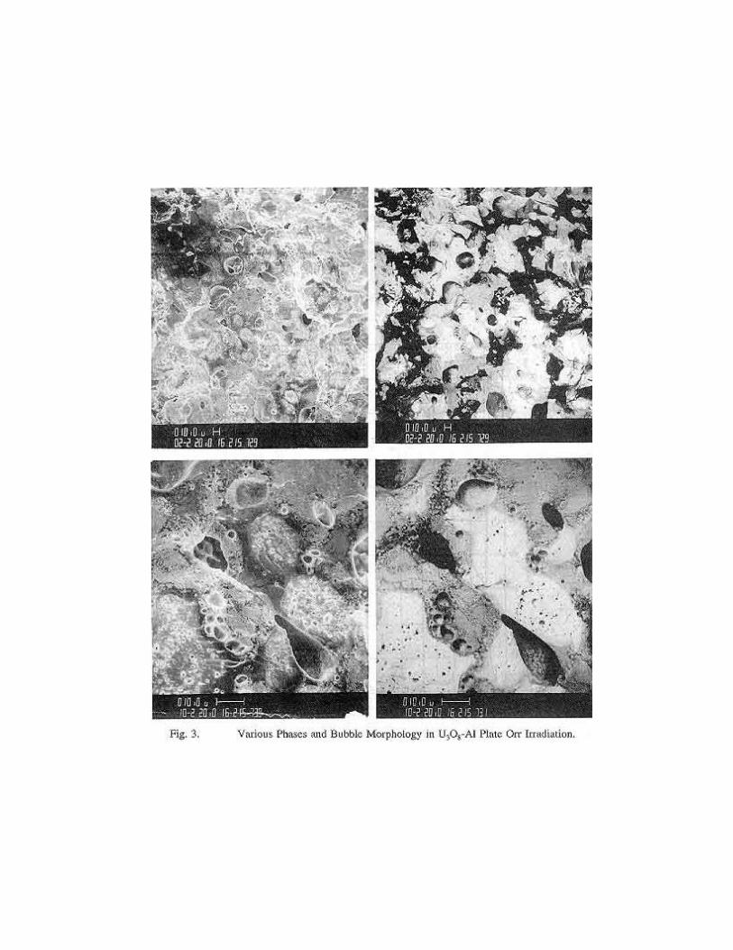
widely used dispersion fuel. As shown in Fig. 3, the phase identified as “2" in Martin’s workactually consists of two phases. These are, judging from electron back-scatter images, most likelythe UAl and Al O reaction products. The other aluminum-containing phase (“3" in Martin’s work)4 2 3
has a U/O ratio near that of U O . This phase is the original U O into which substantial aluminum3 8 3 8
has diffused. The globular phase that contains no aluminum has a U/O ratio equal to that of U O4 9
(see Table I). The microstructure of this reacted U O , combined with the information learned in3 8
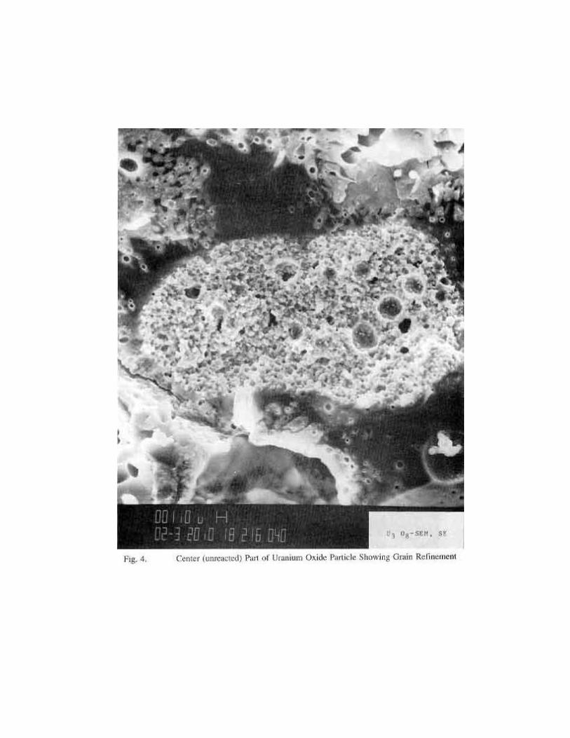
previous work, can help explain the swelling behavior of this dispersion fuel. The globular phase ispresumably U O , a cubic phase similar to UO . The granular appearance of the fracture surface4 9 2
shown in Fig. 4 suggests that the grain refinement previously observed in UO has occurred here and2
that the swelling behavior of this phase is similar to that of UO . Phase “3", U O containing2 3 8(7)
aluminum, has a smooth glassy fracture surface and contains some relatively large gas bubbles. U O3 8
was found to become amorphous during irradiation ; this may account for its appearance and the[8]
evidently high diffusivity of aluminum at these low temperatures.
Table I. Results of Auger Microprobe Analysis onIrradiated U O -Al Dispersion Fuel.3 8
Phase U O Al (at.%) O/Ma
3 23 62 15 2.7 (U O )3 8
4 31 69 0 2.2 (U O )4 9
Oxygen-to-metal ratio.a
More important to the overall swelling behavior is the UAl -Al O mixed reaction phase. We4 2 3
may assume that Al O is amorphous and very plastic due to recoil damage from the finely dispersed2 3
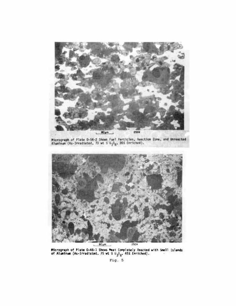
UAl , giving rise to the relatively large bubbles observed to be formed in this phase (see Fig. 5). So4
long as the reacted fuel particles remain largely isolated, as in a moderately loaded dispersion suchas shown in Fig. 1, swelling will be very modest and predictable to a very high burnup. However, inhighly loaded dispersions, where most of the matrix aluminum may be consumed by the reaction,there is a definite limit to fission gas retention of the UAl -Al O phase, as is evident in the4 2 3
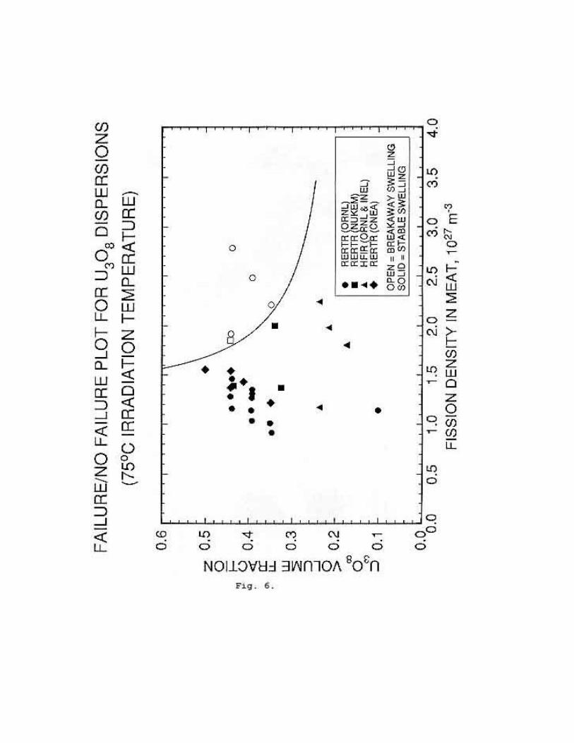
micrograph of the 75 wt.% LEU fuel shown in Fig. 5. Continued fissioning results in rapid swellingdue to very large interconnected bubbles in the reaction phases and, eventually in failure of the fuelplate. The limiting conditions in terms of loading and burnup capability of the fuel are shownschematically in Fig. 6. Here we have used fission density in the meat as opposed to fission densityin the fuel particle as the variable since the original fuel particle has been lost through reaction.

P ' Po23%
13
exp &FD0.1
,
U3O8%43
Al 6 3 UO2 %23
Al2O3
UO2 %43
% x Al 6 UAlx %23
Al2O3.
Experience in the U.S. with UO in aluminum is limited to only a few experimental2
irradiations, for UO never gained the acceptance in the US that U O did, chiefly because of swelling2 3 8
problems encountered during fabrication early in the development of oxide-aluminum fuel plates.However, more recent experimental work has shown that this problem can be eliminated. In testswhere UO and U O dispersions were irradiated together , it was shown that generally the behavior2 3 8
[9]
of UO -Al is similar to that of U O -Al.2 3 8
SWELLING MODELS
During irradiation, fuel plates and tubes increase in diameter (thickness) as a result of swellingof the fuel core. The swelling is a direct result of the accumulation of fission-product elements in thefuel. Although the accumulation of fission products is, to first order, directly proportional to theburnup of U, the resultant swelling is also affected by several microstructural changes that occur235
in the fuel core during irradiation, namely the reaction between the aluminum matrix and the UO fuel,2
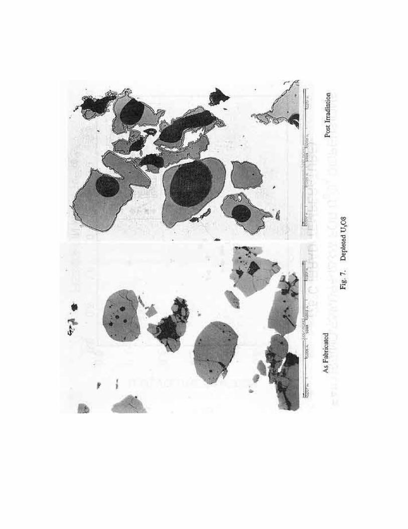
and sintering of the as-fabricated porosity. An important factor in reducing the overall amount of netswelling is radiation-enhanced sintering of fabrication voids. In U O , this effect was first3 8
demonstrated by Reinke , and later confirmed in an experiment by Martin et al. , in which U O[10] [5]3 8
dispersion fuel made with depleted uranium was irradiated. The fabrication voids within the U O3 8
particles, as well as cracks and gaps resulting from fabrication, were found to have sintered tospherical (or elliptical) cavities after irradiation (see Fig. 7). It is well established that an increase indispersant loading also increases fabrication voids, and, although this porosity largely persists to highburnup, as is apparent in Fig. 5, some fractional reduction of the void volume takes place duringsintering, contributing an appreciable amount of negative core swelling in the case of highly loadedfuel. The experiments of Reinke and Adamson indicate that this effect occurs early in the[10] [11]
irradiation and amounts to a 1/3 reduction in void volume. The formula used in DART to calculatethe sintered porosity, P, is as follows:
(1)where P is the as-fabricated core porosity fraction and FD is the core fission density in units of 100
21
cm .-3
The chemical reaction of uranium oxide and aluminum proceeds according to the followingequation:
(2)and
(3)
These reactions result in a net decrease in volume, and therefore represent a negative core

y 2/t ' k exp &Q
RT,
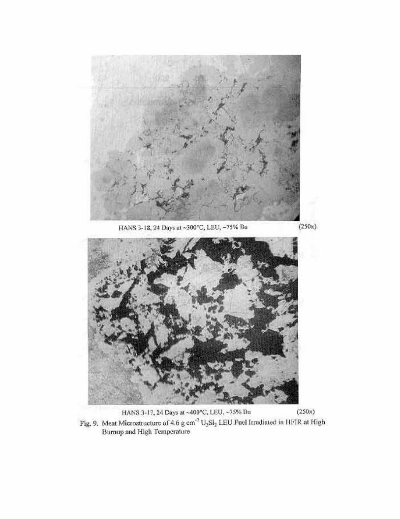
swelling component. Published data from HFIR , MTR , and SRL were used to develop a[12] [13] [14]
correlation for the rate of reaction between U O and aluminum. The correlation, expressed in terms3 8
of the width, y, of the interaction zone at the periphery of an assumed average spherical fuel particleis shown in Fig. 8 and is of an Arrhenius type;
(4)where t in the irradiation time
y the reactor depthk the reaction rate constantQ the activation energy
This correlation predicts the U O -Al reaction, measured by quantitative metallography, of the ORR3 8
miniplates that are used in this analysis (see Figs. 8 and 9).
The DART mechanical analysis addresses the mechanical behavior of dispersion fuel plates,tubes, and fuel rods. The model examines a system of spherical fuel particles surrounded by a largespherical shell of matrix material bonded to an outer shell of aluminum cladding. This approach treatsthe inner sphere as an elastically deforming body and the spherical shell as perfectly plastic. TheDART swelling models provide the driving force for mechanical deformation. The model is deriveddirectly from the equations of equilibrium, compatibility, strain displacement, and the constitutiveequations (stress-strain relationships) coupled with the assumption of incompressibility of plasticstrains. The boundary conditions assume finite radial stresses at the center of the inner sphere, nodiscontinuity in the radial stress at the fuel/matrix interface, and no pressure on the outer surface ofthe spherical shell. It is also assumed that thermal expansion and swelling are not functions of radialposition and that the outer radius of the spherical shell approaches infinity. This approach to thermaland swelling strains is based on calculations that indicate the temperature changes across a fuel plateor rod are small.
No change in yield stress with fluence is considered. Evaluation of available data indicatesthat the change in yield stress due to fluence is negligible. Inclusion of this phenomenon wouldslightly reduce deformation estimates. In addition, the effects of irradiation-enhanced creep andirradiation hardening are not considered. Consideration of these phenomena would require time-dependent deformation analysis, which would add significantly to the complexity and executionefficiency of the DART code. The effects of irradiation-enhanced creep and hardening are accountedfor by the inclusion of a phenomenological factor that multiplies the aluminum yield strength. Thevalue of this factor depends on the geometry of the element, i.e. plate or rod.
The model consists of the stress analysis of a hard sphere of radius a, assumed to behave
elastically, surrounded by a spherical shell with outer radius b of a softer material that is assumed to
behave in a perfectly plastic manner (b>>a). This plastic behavior is assumed to extend out to a
plastic radius r such that a<r <b. This procedure yields an equation for the interfacial pressurec c(radial stress) at the fuel/matrix interface in terms of fuel particle swelling and plastic deformation inthe matrix (i.e., as the interfacial pressure increases, plastic flow is induced in the matrix out to some

Pi ' 2 13
% Inrc
aSy ,
V ro % )V f
V co
'4/3B a 3
4/3B r 3c
'arc
3
,
V fo
V co
)V f
V co
Ph ' Pi '23
1 & InV f
o % )Vf
V eo
$Al Sy ,
radius beyond which only elastic deformation occurs). Based on the results of a general solution tothe problem, an approximation is introduced that avoids simultaneous solution for the interfacialpressure and the radius of plastic deformation. For positive interface pressure P ,i
(5)where S is the yield stress determined from the von Mises criterion for plastic flow. The results ofy
the general solution indicate that r increases rapidly to include most of the matrix aluminum. Thus,cit appears reasonable to make the approximation that the fuel volume fraction is given by
(6)
where is the as-fabricated fuel volume fraction in the core and is the increase in fuel
volume fraction due to processes such as as-fabricated pore closure and fuel particle swelling. Thus,from Eqs. 5 and 6,
(7)where P has been identified with the hydrostatic stress within the fuel particle P , and $ is ai h Alphenomenological factor (discussed above) that has been introduced to account for the effects ofirradiation (e.g., irradiation-enhanced creep and hardening). The value of $ used for describing fuelAlplates and tubes is 0.13.
The growth of fission gas bubbles depends on the hydrostatic pressure P in the fuel adjacenth
to the bubble surface. Equation 7 relates P to the overall fuel volume fraction and the aluminumhyield stress and therefore provides an estimate of the average hydrostatic stress within the fuelparticle. As seen in the above sections, a gradient in fuel composition will, in general, exist acrossthe fuel particle. This phase gradient will give rise to the gradient in swelling and, thus, a gradientin stress. To realistically calculate the fission gas bubble size distributions and, hence, fuel swelling,a mechanism for evaluating the stress gradient within the fuel particle must be introduced.
DART employs a radial nodalization scheme to characterize temperature, stress, swelling, andphase gradients. As discussed above a phenomenological factor has been introduced in theelastic/perfectly plastic analysis of fuel particle deformation within an aluminum matrix to account forthe effects of irradiation (e.g., irradiation-enhanced creep and hardening) without resorting to a much-more-complicated time-dependent deformation analysis. The fuel-aluminum reaction moves from thefuel particle surface inward. When the reaction front has crossed a fuel node, that node is considered

TCS ' FPS % RPS % AFP ,
$Rp ' $al / [(1&VAM/0.01) % 1],
transformed to the reaction-product phase, and the nodal volume change due to the reaction isimplemented, as well as the volume change in the matrix due to the loss of aluminum. The total coreswelling (TCS) is given by
(8)
where FPS = fission product swelling, RPS = reaction product swelling, and AFP = as-fabricatedporosity. The swelling fuel particles cause yielding of the matrix aluminum and cladding deformation.During the initial phase of the irradiation, when both the fuel volume fraction and the volume fractionof reaction product is considerably less than the volume fraction of aluminum matrix, the swelling rateprimarily depends on the plastic yielding of the aluminum matrix and cladding. As amount of reactionproduct increases, the swelling rate will depend more on the "yielding" of the amorphous reactionproduct than on the plastic yielding of the remaining aluminum matrix. It is assumed in the analysisthat when the aluminum volume fraction reaches 10%, the effect of the yielding of the amorphousreaction product becomes important. At this point, the effective yield strength $ S of aluminumAl yin Eq. 7 is replaced with the effective yield strength of the two-phase mixture, i.e.,
(9)where VAM is the aluminum volume fraction. Thus, from Eq. 9, when the matrix aluminum hascompletely disappeared, the effective yield strength is reduced by a factor of 3.5.
CALCULATIONS
A. U O -Al3 8
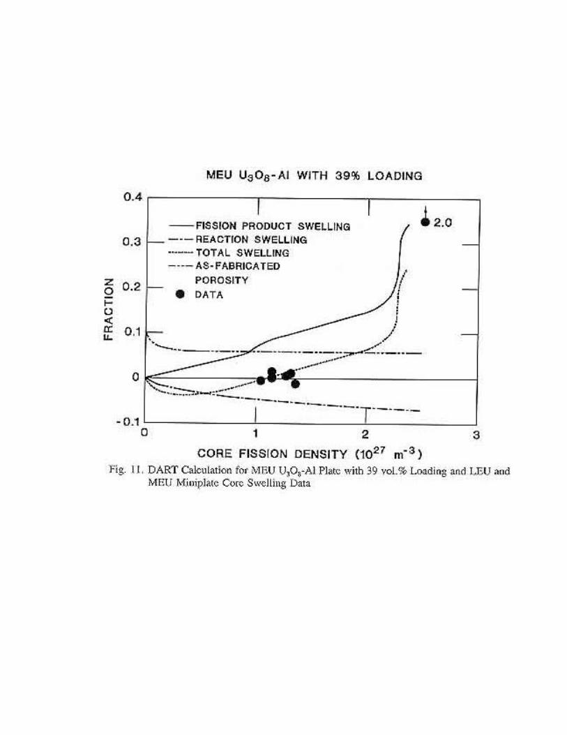
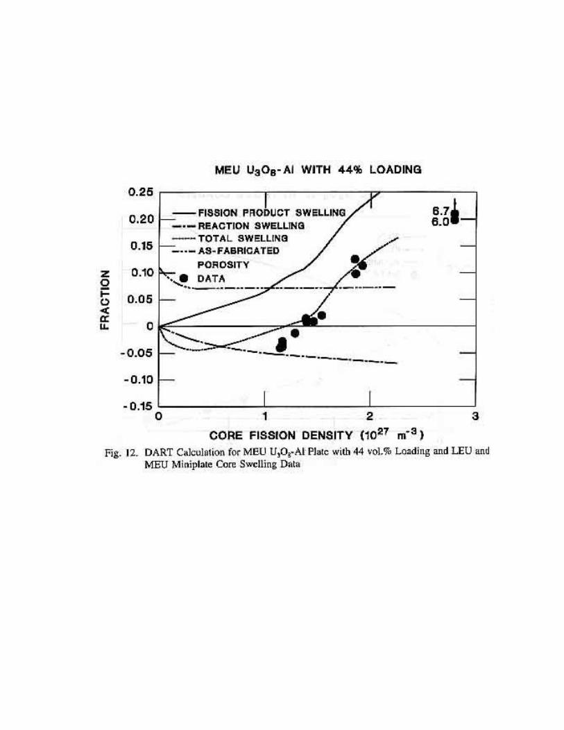
Figures 10-12 show the results of DART calculations at 100EC for fission-product swelling,reaction swelling, total swelling, and as-fabricated porosity as a function of the core fission densitycompared with data from LEU and MEU U O -Al irradiations of plates with with fuel loadings of 443 8
vol.% (Fig. 12), 39 vol.% (Fig. 11), and 35 vol.% (Fig. 10), respectively. The total swelling duringthe early phase of irradiation is negative due to the sintering of the as-fabricated porosity and coreshrinkage due to the reaction between the U O and the matrix aluminum. Subsequent to the3 8
sintering of the as-fabricated porosity, the total swelling increases due to fission product swelling.Recrystalization of the fuel leads to enhanced swelling rates (at about 1 x 10 fissions m in Figs. 10-27 -3
12). As the irradiation proceeds and the fuel continues to react with the matrix aluminum, the fuelvolume fraction increases while the aluminum volume fraction decreases (see Fig. 13). Thus, themorphology of the core evolves from U O fuel particles in an aluminum matrix to UO (or U O )3 8 2 4 9
particles surrounded by increasing amounts of UAl and Al O reaction products, and decreasingx 2 3
amounts of aluminum matrix. Al O is amorphous, and the composite reaction product is presumably2 3
much softer and more ductile than the matrix aluminum. In addition, fission gas bubbles grow at anenhanced rate in the irradiated amorphous reaction product. This is analogous to bubble behaviorin irradiated U Si.3

The transition from swelling fuel particles surrounded by a yielding aluminum matrix to fuelparticles surrounded by a considerably softer reaction product matrix is described by the effectiveyield stress formulation given in Eqs. 7-9; that is, when the aluminum volume fraction reaches 10%(see Fig. 13), the assumption is made that the presence of the reaction product starts affecting theeffective yield stress. The effective yield stress of the reaction product is assumed to be a factor of3.5 times softer than that of the matrix aluminum.
This transition occurs in the 44 vol.% case (Fig. 12) at about 1.5 x 10 fissions m where the27 -3
swelling rate increases due to the presence of fission gas bubbles in the "weaker" amorphous reactionproduct. As can be seen from Fig. 12, this formulation provides a plausible interpretation of the data.The calculations shown in Figs. 11 and 13 for the 39 vol.% case are also in agreement with theobservations. The 39 vol.% case reaches 10% aluminum volume fraction at about 2.25 x 10 fissions27
m (Fig. 13) and failure of the plate (200% swelling) occurs by 2.5 x 10 fissions m . In contrast-3 27 -3
to the 39 and 44 vol.% fuel loading cases discussed above, the 35% case remains stable throughoutthe irradiation. The calculations for this irradiation, shown in Fig. 10, predict that the irradiation isstable because the aluminum volume fraction never drops below 10%.
The model predicts a much-more-rapid failure of the 39 vol.% plate than of the 44 vol.%plate, as seen by comparing Figs 11 and 12. The explanation is as follows. Since a much-longerirradiation time is required to reduce the aluminum volume fraction to 10% in the 39 vol.% plate thanin the 44 vol.% plate, a much larger amount of fission gas is available to drive the swelling, resultingin a more rapid expansion of the gas bubbles.
B. UO -Al2
To calculate the swelling in Russian tubular MR elements, it is assumed that the modelsderived for U O also apply to UO . Mechanical analysis shows that the relatively large-diameter,3 8 2
thin-wall fuel tubes behave as fuel plates. It is further assumed that the average UO particle size is2
80 µm, and the fuel loading at 4 g LEU cm is 42 vol.%. Because core temperature and as-fabricated-3
porosity are not known, two values for each of these parameters were chosen, i.e., 100EC and 140EC,and 5 and 10 vol.%, respectively.
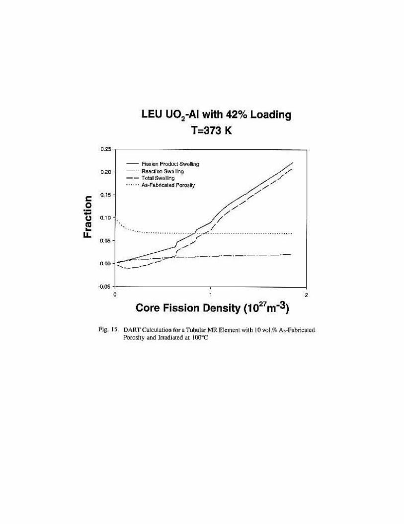
The results shown in Figs. 14 and 15 indicate that for the 100EC cases, the core swelling ismoderate and no pillowing of the tubes is anticipated below ~86% burnup of the U. Fig. 16 shows235
the predicted change in core constituent volume fractions as the irradiation proceeds for the case with5% as-fabricated porosity.
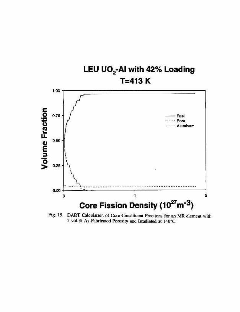
In the case of 140EC, shown in Figs. 17 and 18, the core swelling is much larger, ~30% at fullburnup. This is due to the fact that all matrix aluminum is consumed early in the irradiation (see Fig.19) and fission gas bubble growth in the reaction product [occurs over a relatively long irradiationinterval. Based on the U O experience (see Figs. 11 and 12), swelling values of -20% in a fully3 8
reacted core are likely to be either at the threshold of or already in the pillowing stage.
CONCLUSIONS
The DART aluminum-fuel interaction models were developed based on U O -Al irradiation3 8
data. An initial evaluation of UO -Al data indicates that the aluminum matrix/fuel reaction in UO2 2
is similar to that in U O -Al. Excessive deformation of the tubular fuel element occurs when the3 8
aluminum volume fraction decreases to about 10%. At this point, fuel particle swelling driven bygaseous fission products is restrained by a "weak" amorphous reaction product and the relatively"weak" tube wall. The combination of an aluminum volume feraction < 10% and meat swelling >20% provides a breakaway swelling criterion based on the analysis of the U O -Al irradiation data.3 8
The DART calculations predict that LEU UO -Al with a 42% fuel volume loading (4 g U/cm ) and2-3
5 vol.% initial porosity irradiated at a fuel temperature of 413 K will undergo breakaway swelling ata core burnup of about 1.12 x 10 fission m (~63% U burnup). On the other hand, if the27 -3 235
irradiation temperature is lowered to 373 K, breakaway swelling is not predicted to occur until 1.47x 10 fissions m (~86% U burnup).27 -3 235
REFERENCES
1. G. L. Copeland, (ORNL), and J. L. Snelgrove, (ANL), "Examination of Irradiated High-U-Loaded U O -Al Fuel Plates," 1982 International Meeting on Research and Test Reactor Core3 8
Conversions From HEU to LEU Fuels, Argonne, IL (1982).
2. J. Gómez, R. Morando, E. E. Pérez and D. R. Giorsetti, (CNEA), G. L. Copeland, (ORNL),G. L. Hofman and J. L. Snelgrove, (ANL), "Postirradiation Examination of High-U-LoadedLow-Enriched U O , UAl , and U Si Test Fuel Plates, 1984 International Meeting on3 8 2 3
Reduced Enrichment for Research and Test Reactors, Argonne, IL (1984).
3. M. F. Hrovat and H.-W. Hassel, (NUKEM), "Recent Status and Future Aspect of Plate TypeFuel Element Technology with High Uranium Density at NUKEM," 1982 InternationalMeeting on Research and Test Reactor Core Conversions from HEU to LEU Fuels, Argonne,IL (1982).
4. J. Rest, J. L. Snelgrove, and G. L. Hofman, (ANL), "DART Model for Thermal Conductivityof U Si Aluminum Dispersion Fuel," 1995 International Meeting on Reduced Enrichment for3 2
Research and Test Reactors, Paris, France (1995).
5. M. M. Martin, et al., ORNL-4856.
6. G. L. Hofman, et al., Nucl. Tech. 72 (1986).
7. J. Rest and G. L. Hofman, J. Nucl. Mater., 210, pp 187-202 (1994).
8. R. M. Berman, et al., JNM 2 (1960).
9. G. W. Gibson, IDO-16934 (1963).
10. Reine, ANL-6665 (1963).
11. G. M. Adamson, et al., Plansee Proc. (1961)."Powder Metallurgy in the Nuclear Age", Springer Verlag, Vienna, Austria (1962).
12. A. E. Richt, et al., ORNL-4714 (1971).
13. M. J. Graber, et al., IDO-17154 (1965).
14. J. L. Snelgrove, et al., "Evaluation of Existing Technology Base for Candidate Fuels for theHWR-NPR," ANL/NPR-93/002 (1993).

TABLE IISWELLING DATA FOR U O -AL MINIPLATES3 8
Original Volume Fraction Core Fission
Plate No. Wt.% U O U O Al Voids Density Swelling3 8 3 8
(X10 ) %21
O-59-3 25.9 10.1 88.7 1.2 1.14 3.0O-49-4 65.1 34.8 57.8 7.4 0.92 1.0O-56-4 65.0 35.0 58.2 6.9 0.92 0.9O-52-2 65.0 34.5 57.5 7.9 0.91 0.1O-52-1 65.0 34.5 57.5 7.9 0.91 0.0O-53-4 64.9 35.1 58.6 6.3 1.01 1.1O-46-6 64.0 34.8 58.1 7.1 2.21 9.7
O-57-1 70.0 39.2 51.9 8.9 1.26 0.5O-57-2 70.0 39.2 51.8 9.0 1.27 0.3O-54-1 69.9 39.5 52.5 8.0 1.27 0.4O-50-4 70.0 39.2 52.0 8.8 1.31 0.9O-50-5 69.9 39.2 52.1 8.6 1.35 1.2O-50-6 69.9 39.2 52.1 8.7 1.35 1.2O-50-2 70.0 39.2 51.9 8.9 1.03 -0.7O-57-4 70.0 39.4 52.1 8.6 1.04 -0.7O-54-6 69.9 39.4 52.3 8.3 1.14 0.0O-54-2 70.0 39.5 52.4 8.1 1.14 1.3O-47-2 69.9 39.2 52.1 8.7 2.48 209.0*
O-51-1 74.9 43.9 45.4 10.7 1.16 -3.1O-59-2 74.9 43.7 45.2 11.0 1.15 -3.8O-51-5 75.0 44.0 45.4 10.5 1.16 -2.8O-58-4 75.0 43.9 45.2 10.9 1.16 -3.8O-58-6 75.0 43.9 45.2 10.9 1.16 -3.6O-55-4 74.9 44.3 45.8 9.9 1.28 -1.3O-55-3 75.0 44.2 45.4 10.4 1.28 -1.3O-48-2 75.1 44.2 45.2 10.7 1.92 11.2O-48-1 75.0 43.9 45.3 10.8 2.78 601.0*O-48-6 74.9 43.9 45.4 10.7 2.78 670.0*O-58-7 74.9 43.9 45.3 10.8 1.46 0.9
304N 61.8 32.6 62.2 5.2 1.37 2.1308N 61.9 32.5 62.0 5.5 1.37 1.6405N 63.8 34.0 59.5 6.5 2.00 2.9407N 63.8 34.0 59.6 6.4 2.00 3.0
505N 74.6 43.5 45.8 10.7 1.39 0.9506N 73.9 43.4 47.5 9.1 1.39 1.5613N 75.0 44.3 45.7 10.0 1.86 9.8614N 75.0 44.2 45.5 10.3 1.85 12.6
RA-209 64.7 35.0 58.9 6.2 1.22 1.7RA-218 71.9 41.2 49.8 9.0 1.43 1.8RA-219 64.9 34.8 58.2 7.0 1.21 1.8RA-222 74.9 44.2 45.8 10.0 1.54 2.2
* Pillowed PlatesO-xx-x Oak Ridge National LabxxxN NUKEMRA-xxx CNEA