Ironless in-wheel hub motor design by using multi … · Ironless In-Wheel Hub Motor Design by...
5
Ironless In-Wheel Hub Motor Design by Using Multi-Domain Finite Element Analyses Oliver Winter ∗ , Stephan Ucsnik § , Michael Rudolph ∗ , Christian Kral ∗ , Erich Schmidt ‡ , AIT Austrian Institute of Technology, Mobility Department, ∗ Electric Drive Technologies, § Light Metal Technologies, 1210 Vienna, Austria, Email: [email protected] ‡ Vienna University of Technology, Institute of Energy Systems and Electrical Drives, 1040 Vienna, Austria Abstract—In this paper, a lightweight ironless axial flux per- manent magnet drive concept is presented. The in-wheel hub motor has a high torque to weight ratio and achieves a high efficiency, which extends the operation range of battery powered vehicles. The steps from preliminary design to manufacturing of the components are described. The paper includes Finite Element Analyses in different physical domains. NOMENCLATURE CFD Computational fluid dynamics. CFRP Carbon fibre reinforced plastic. EM Electromagnetic calculation. FEA Finite element analysis. FVA Finite volume analysis. GRP Glass fibre reinforced plastic. ICE Internal combustion engine. I. I NTRODUCTION A mayor drawback of electric vehicles is nowadays their limited operation range. Consequently, various drive train concepts like many types of hybrid and near wheel electrical motors have been developed. Although various concept cars and even standard models were presented on the market, their limited range in comparison to ICE powered vehicles is still an unresolved problem. Mainly because of weight limitations, the energy-storage capacity of a battery is significantly smaller than that of a fuel tank. In-wheel hub motors improve this situation because they minimize the vehicle mass. The added unsprung mass does not impair driving comfort or safety [1], [2]. Among all types of electric machines, axial flux machines provide the highest torque to volume ratio if the radial diameter is not strictly limited [3], [4]. The most efficient, light weighted topology is the air cored axial flux machine equipped with magnets in Halbach arrangement [5], [6]. If both minimum mass and high efficiency are desired, this topology is preferred and it is therefore used in the proposed design. The effect of flux concentration due to changing magnetiza- tion patterns in magnetic materials was discovered in 1973 [7]. Later, it was named after K. Halbach who worked on undulators for the production of synchrotron radiation [8]. Applied to rotating electric machines, Halbach magnet arrays produce higher torque as magnetically-backed rotors [9]. A 2D representation of a double sided Halbach magnet array is shown in Fig. 1. Airgap winding Halbach magnet array Halbach Magnet array (i) (ii) Fig. 1. Double sided Halbach magnet array arrangement without back iron, (i) magnetization pattern, (ii) resulting field pattern II. SPECIFICATION AND PROJECT WORKFLOW The main objective of most in-wheel concepts (e.g. Michelin ”active wheel”, Siemens VDO/Continental ”ecorner”, Volvo Protean ”ReCharge”, Mitsubishi ”MiEV”) is the direct sub- stitution of the ICE and the gearbox. Such in-wheel concepts are used for vehicles from A-class up to transporters. The continuous power output for the given examples ranges from 20 to 64 kW per wheel. Assuming a nominal efficiency of η = 92%, the nominal thermal losses of each electric machine are in the range from 1.6 kW to 5.12 kW. Due to limited space inside a standard rim, it is assumed that the heat transfer surface to the cooling medium (mostly liquid cooled) TABLE I VIRTUAL VEHICLE SPECIFICATION Description Symbol Nominal value Vehicle mass mvv 250 kg Frontal area Avv 1.8 m 2 Aerodynamic coefficient cw 0.220 Rolling coefficient cr 0.008 Nominal speed vnom 80 km/h 978-1-4673-1301-8/12/$31.00 ©2012 IEEE 2012 International Symposium on Power Electronics, Electrical Drives, Automation and Motion 1474
-
Upload
dinhnguyet -
Category
Documents
-
view
227 -
download
1
Transcript of Ironless in-wheel hub motor design by using multi … · Ironless In-Wheel Hub Motor Design by...

Ironless In-Wheel Hub Motor Design by UsingMulti-Domain Finite Element Analyses
Oliver Winter∗, Stephan Ucsnik§, Michael Rudolph∗, Christian Kral∗, Erich Schmidt‡,AIT Austrian Institute of Technology, Mobility Department,
∗Electric Drive Technologies, §Light Metal Technologies, 1210 Vienna, Austria, Email: [email protected]‡Vienna University of Technology, Institute of Energy Systems and Electrical Drives, 1040 Vienna, Austria
Abstract—In this paper, a lightweight ironless axial flux per-manent magnet drive concept is presented. The in-wheel hubmotor has a high torque to weight ratio and achieves a highefficiency, which extends the operation range of battery poweredvehicles. The steps from preliminary design to manufacturing ofthe components are described. The paper includes Finite ElementAnalyses in different physical domains.
NOMENCLATURE
CFD Computational fluid dynamics.
CFRP Carbon fibre reinforced plastic.
EM Electromagnetic calculation.
FEA Finite element analysis.
FVA Finite volume analysis.
GRP Glass fibre reinforced plastic.
ICE Internal combustion engine.
I. INTRODUCTION
A mayor drawback of electric vehicles is nowadays their
limited operation range. Consequently, various drive train
concepts like many types of hybrid and near wheel electrical
motors have been developed. Although various concept cars
and even standard models were presented on the market, their
limited range in comparison to ICE powered vehicles is still
an unresolved problem. Mainly because of weight limitations,
the energy-storage capacity of a battery is significantly smaller
than that of a fuel tank. In-wheel hub motors improve this
situation because they minimize the vehicle mass. The added
unsprung mass does not impair driving comfort or safety
[1], [2]. Among all types of electric machines, axial flux
machines provide the highest torque to volume ratio if the
radial diameter is not strictly limited [3], [4]. The most
efficient, light weighted topology is the air cored axial flux
machine equipped with magnets in Halbach arrangement [5],
[6]. If both minimum mass and high efficiency are desired, this
topology is preferred and it is therefore used in the proposed
design.
The effect of flux concentration due to changing magnetiza-
tion patterns in magnetic materials was discovered in 1973
[7]. Later, it was named after K. Halbach who worked on
undulators for the production of synchrotron radiation [8].
Applied to rotating electric machines, Halbach magnet arrays
produce higher torque as magnetically-backed rotors [9]. A
2D representation of a double sided Halbach magnet array is
shown in Fig. 1.
Airgap winding
Halbach magnet array
Halbach Magnet array
(i)
(ii)
Fig. 1. Double sided Halbach magnet array arrangement without back iron,(i) magnetization pattern, (ii) resulting field pattern
II. SPECIFICATION AND PROJECT WORKFLOW
The main objective of most in-wheel concepts (e.g. Michelin
”active wheel”, Siemens VDO/Continental ”ecorner”, Volvo
Protean ”ReCharge”, Mitsubishi ”MiEV”) is the direct sub-
stitution of the ICE and the gearbox. Such in-wheel concepts
are used for vehicles from A-class up to transporters. The
continuous power output for the given examples ranges from
20 to 64 kW per wheel. Assuming a nominal efficiency
of η = 92%, the nominal thermal losses of each electric
machine are in the range from 1.6 kW to 5.12 kW. Due to
limited space inside a standard rim, it is assumed that the heat
transfer surface to the cooling medium (mostly liquid cooled)
TABLE IVIRTUAL VEHICLE SPECIFICATION
Description Symbol Nominal value
Vehicle mass mvv 250 kg
Frontal area Avv 1.8 m2
Aerodynamic coefficient cw 0.220
Rolling coefficient cr 0.008
Nominal speed vnom 80 km/h
978-1-4673-1301-8/12/$31.00 ©2012 IEEE
2012International Symposium on Power Electronics,Electrical Drives, Automation and Motion
1474

TABLE IIMOTOR DESIGN SPECIFICATION
Description Symbol Nominal value
Continuous output power Pnom 3500 W
Peak power (10 s) Ppeak 5·Pnom
Speed at 80 km/h nn 660 rpm
Continuous torque Tnom 55 Nm
Peak torque (10 s) Tpeak 5·Tnom
Nominal torque/active weight 4.8 Nm/kg
Peak torque/active weight 24 Nm/kg
is not sufficient for reliable operation, especially in case of
peak loads. Consequently, the aim of this paper is to present
the development of an in-wheel hub motor with maximum
efficiency and minimum mass added to the vehicle. High
efficiency should maximize the operation range and prevent
thermal overloads. The considered machine should drive a vir-
tual vehicle with specifications listed in Table I. If in a different
vehicle the mass exceeds these specifications, an additional
hub motor may be added to achieve the desired performance.
Based on the specifications of Table I, the required continuous
power was calculated to reach the maximum speed. The rolling
resistance of the tires Fr , the aerodynamic drag Fd, and the
force Frise required to overcome an assumed slope of an angle
α = 20◦ resulted in the motor design specification given in
Table II. The required power Pnom was calculated according
to
Pr = Frvnom = crgmvvvnom,
Pd = Fdvnom =1
2cwρAvvv
3nom,
Prise = Frisevnom = mvvg sin(α)vnom,
Pnom =Pr + Pd + Prise
η(1)
with an assumed drive train efficiency η = 92 %. The other
parameters are the mass density of air ρ = 1.25 kg/m3 and
the constant of gravity g = 9.81 m/s2. To reach comfortable
acceleration but within tolerable temperature rise, the desired
peak power was set to 5 times the continuous power for a
period of 10 s. This overload case has to be verified by
CFD and drive cycle analysis, which is partially covered in
Subsection III-D.
The comparison of torque to weight ratios is common
practice [10], but without taking the cooling system into
account, it may be misleading. Nevertheless, the commercially
available CSIRO motor with standard magnet arrangement [5]
stands out by 97.5% efficiency and 1.95 Nm/kg (active parts).
By adding forced air cooling, the continuous torque to weight
ratio of was increased to 4.7 Nm/kg with unchanged efficiency.
The CSIRO system serves as a benchmark for the motor to be
developed in this paper. The goal is to achieve the increased
torque to weight ratio not only theoretically but practically
proven by a prototype. The design and validation workflow is
shown in Fig. 2.
Virtual vehicle specification
Analytical calculation
Preliminary design
EM
FEA
Structural
FEA
CFD
FVA
Temperatures,
cooling system
specification
Material stress
and deformation,
fatigue analysis
Material specification, joining
techniques, partial functional models
Manufacturing and assembly
Testing and validation
Losse
s
Torq
ue
Forc
es
Fig. 2. Design and validation work flow
III. METHODS
A. Analytical calculation and mechanical design
Basic parameters like the feasible number of magnet seg-
ments per magnetic wavelength and the general size of the
motor were calculated according to [11]. The peak magnetic
flux density B for segmented Halbach arrays with the magnet
height hm and the number of magnets nm per spatial period
λ is given by
B = Br
⎛⎝1− e
−2πhm
λ
⎞⎠ si
(π
nm
). (2)
Br denotes the remanent magnetic flux density of the chosen
magnet material. Under the assumption of sinusoidal current
Irms and magnetic flux φ derived by B, the electromagnetic
torque T is
T =m1√2pNφIrms. (3)
Here, m1 is the number of phases, p is the number of pole
pairs, and N is the number of turns per phase. The general
design is shown in Fig. 3. The wheel hub is an important
mechanical part for the motor design. The weight of the
vehicle and the motor torque have to be transferred between
the chassis and motor. Two symmetric CFRP half rims are
mounted onto the hub with deep groove ball bearings and are
1475

(i)
(iii) (iii)
(iv)
(v)
(ii) (ii)
(vi)
Fig. 3. Cross section of in-wheel hub motor: (i) light metal hub, (ii)bearings, (iii) two symmetric CFRP half rims, (iv) air cored winding withGRP connection to the hub, (v) two Halbach magnet array rings, (vi) brakedisk
bolted together at their outer circumference (just inside the
tyre). Two rim edges provide the support for a standard tire.
The inner surface of each half rim is connected to the magnet
array ring to provide the magnetic field which interacts with
the winding. The air cored winding consists of Litz wires to
limit eddy current losses and is encapsulated by casted resin
containing filler. The inner winding head is connected to the
spoked hub using multiple layers of GRP and membranes
between the four hub spokes.
B. Electromagnetic design and FEA
As indicated in Fig. 2, 3D electromagnetic FEA is used
for determining the input data for the CFD and the structural
analyses. A detailed winding and magnet array section model
with approximately 120 000 second order tetrahedral elements
was created and the geometry is shown in Fig. 4. The magne-
tostatic solver calculates the magnet attraction forces between
the two CFRP rims, evolved torque, flux density distributions,
and winding losses. A detailed design study of the magnet
shapes and their effect on the evolved torque as well as the
induced voltage characteristic are given in [12].
C. Structural FEA
Structural FEAs of the mayor parts have been carried out to
analyse different load cases like acceleration during cornering.
The considered loads are given in Table III. The half rims were
modelled with quasi-isotropic CFRP laminat and combinations
of the load cases like cornering with acceleration were applied.
The result for the emergency brake load case result is shown in
Fig. 5. The failure criterion according the theory of Puck was
Fig. 4. 3D motor section for electromagnetic FEA
TABLE IIIMECHANICAL LOAD CASES
Description Symbol Nominal value
Vehicle weight (mvv ·g) Fvvm 2450 N
Maximum torque Tpeak 275 Nm
Emergency mechanical braking torque Temb 260 Nm
Magnet attraction force Fmag 12 kN
Cornering transverse force (1.5·mvv ·g) Fct 3680 N
Curb contact (angle 30◦, 2.5·mvv ·g) Fcc 6130 N
Tire pressure ptire 5 bar
used for the judgement of critical fibre and inter-fibre failure.
Consequently, the maximum stress has to be transformed into
the fibre direction and perpendicular to the fibre at the volume
of interest. The number of CFRP layers were increased until
criterion was fulfilled.
The primary purpose of the wheel hub is to provide the
Fig. 5. CFRP structural FEA result, stress plot, scale: -43.5 – 43.5 MPa,applied load: braking torque, vehicle mass, tire pressure and corneringtransverse force
1476
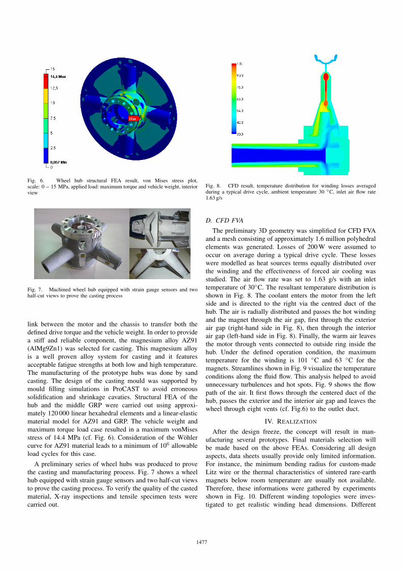
Fig. 6. Wheel hub structural FEA result, von Mises stress plot,scale: 0 – 15 MPa, applied load: maximum torque and vehicle weight, interiorview
Fig. 7. Machined wheel hub equipped with strain gauge sensors and twohalf-cut views to prove the casting process
link between the motor and the chassis to transfer both the
defined drive torque and the vehicle weight. In order to provide
a stiff and reliable component, the magnesium alloy AZ91
(AlMg9Zn1) was selected for casting. This magnesium alloy
is a well proven alloy system for casting and it features
acceptable fatigue strengths at both low and high temperature.
The manufacturing of the prototype hubs was done by sand
casting. The design of the casting mould was supported by
mould filling simulations in ProCAST to avoid erroneous
solidification and shrinkage cavaties. Structural FEA of the
hub and the middle GRP were carried out using approxi-
mately 120 000 linear hexahedral elements and a linear-elastic
material model for AZ91 and GRP. The vehicle weight and
maximum torque load case resulted in a maximum vonMises
stress of 14.4 MPa (cf. Fig. 6). Consideration of the Wohler
curve for AZ91 material leads to a minimum of 106 allowable
load cycles for this case.
A preliminary series of wheel hubs was produced to prove
the casting and manufacturing process. Fig. 7 shows a wheel
hub equipped with strain gauge sensors and two half-cut views
to prove the casting process. To verify the quality of the casted
material, X-ray inspections and tensile specimen tests were
carried out.
Fig. 8. CFD result, temperature distribution for winding losses averagedduring a typical drive cycle, ambient temperature 30 ◦C, inlet air flow rate1.63 g/s
D. CFD FVA
The preliminary 3D geometry was simplified for CFD FVA
and a mesh consisting of approximately 1.6 million polyhedral
elements was generated. Losses of 200 W were assumed to
occur on average during a typical drive cycle. These losses
were modelled as heat sources terms equally distributed over
the winding and the effectiveness of forced air cooling was
studied. The air flow rate was set to 1.63 g/s with an inlet
temperature of 30◦C. The resultant temperature distribution is
shown in Fig. 8. The coolant enters the motor from the left
side and is directed to the right via the centred duct of the
hub. The air is radially distributed and passes the hot winding
and the magnet through the air gap, first through the exterior
air gap (right-hand side in Fig. 8), then through the interior
air gap (left-hand side in Fig. 8). Finally, the warm air leaves
the motor through vents connected to outside ring inside the
hub. Under the defined operation condition, the maximum
temperature for the winding is 101 ◦C and 63 ◦C for the
magnets. Streamlines shown in Fig. 9 visualize the temperature
conditions along the fluid flow. This analysis helped to avoid
unnecessary turbulences and hot spots. Fig. 9 shows the flow
path of the air. It first flows through the centered duct of the
hub, passes the exterior and the interior air gap and leaves the
wheel through eight vents (cf. Fig.6) to the outlet duct.
IV. REALIZATION
After the design freeze, the concept will result in man-
ufacturing several prototypes. Final materials selection will
be made based on the above FEAs. Considering all design
aspects, data sheets usually provide only limited information.
For instance, the minimum bending radius for custom-made
Litz wire or the thermal characteristics of sintered rare-earth
magnets below room temperature are usually not available.
Therefore, these informations were gathered by experiments
shown in Fig. 10. Different winding topologies were inves-
tigated to get realistic winding head dimensions. Different
1477

Fig. 9. CFD result, temperature distribution along the streamlines, averageddrive cycle winding losses, ambient temperature 30 ◦C, inlet air velocity 2 m/s,exterior view
(i) (ii)
(iii)
Fig. 10. Functional models, (i) Air gap winding, (ii) Double sided Halbachmagnet array (9 pieces 10x10x45 mm each), (iii) Moulded air gap winding
resins were used for manufacturing quarter models of the
molded air gap winding. Fig. 10 (iii) shows a design with
polyurethane resin. Significant magnetic forces occur during
the assembly of the Halbach arrays. Small scale linear arrays
were manufactured in order to determine different assembly
strategies. An example is shown in Fig. 10 (ii). Degrading
effects ranging from –20 ◦C to the maximum operating tem-
perature were measured and evaluated for different magnet ma-
terial grades. Electromagnetic FEA and measurements showed
an augmented temperature degrading effect within segmented
Halbach arrays [13].
V. CONCLUSION
A concept for an ironless in-wheel hub motor and the work
flow towards manufacturing and assembly were presented in
this paper. The virtual vehicle specification and analytical de-
sign variations lead to a preliminary design and the creation of
3D models. 3D EM FEAs demonstrated the functionality and
provided source data for CFD FVA illustrating the temperature
distribution and the heat flows of the cooling system. Structural
FEAs yielded the performance and fatigue behavior of the
used components. Moreover, several concepts for manufactur-
ing the components were devised and experimentally tested.
These concepts include joining and encapsulation techniques,
winding arrangement, and magnet assembly.
VI. ACKNOWLEDGMENT
The authors gratefully acknowledge the support of
the Austrian Research Promotion Agency (Oesterreichische
Forschungsfoerderungsgesellschaft mbH, Klima- und Energie-
fonds, Neue Energien 2020) for the research project 829727
HeAL - High efficient ironless drive for lightweight vehiclesand the project partner DFM technologies.
REFERENCES
[1] M. Anderson and D. Harty, “Unsprung mass with in-wheel motors-mythsand realities,” in 10th International Symposium on Advanced VehicleControl, (AVEC’10), Aug. 2010, pp. 261–266.
[2] D. van Schalkwyk and M. Kamper, “Effect of hub motor mass onstability and comfort of electric vehicles,” in IEEE Vehicle Power andPropulsion Conference, (VPPC’06), Sept. 2006, pp. 1–6.
[3] Z. Zhang, F. Profumo, and A. Tonconi, “Axial flux interior PM syn-chronous motors for electric vehicle drives,” Symposium on PowerElectronics Electrical Drives Automation and Advanced Electric Motors,(SPEEDAM’94), pp. 323–328, Jun. 1994.
[4] F. Profumo, F. Eastham, A. Tenconi, and G. Gianolio, “”Plastic” electricmotors: a viable solution for axial flux machines,” in Proceedingsof the 2002 IEEE International Symposium on Industrial Electronics,(ISIE’02), vol. 1, 2002, pp. 1–10.
[5] H. Lovatt, V. Ramsden, and B. Mecrow, “Design of an in-wheel motorfor a solar-powered electric vehicle,” IEE Proceedings Electric PowerApplications, vol. 145, no. 5, pp. 402–408, Sept. 1998.
[6] R. Al Zaher, S. de Groot, H. Polinder, and P. Wieringa, “Comparisonof an axial flux and a radial flux permanent magnet motor for solarrace cars,” in XIX International Conference on Electrical Machines,(ICEM’2010), Sept. 2010, pp. 1–6.
[7] J. Mallinson, “One-sided fluxes – A magnetic curiosity?” IEEE Trans-actions on Magnetics, vol. 9, no. 4, pp. 678–682, Dec. 1973.
[8] K. Halbach, “Design of permanent multipole magnets with oriented rareearth cobalt material,” Nuclear Instruments and Methods, vol. 169, no. 1,pp. 1–10, 1980.
[9] J. Ofori-Tenkorrang and J. Lang, “A comparative analysis of torqueproduction in Halbach and conventional surface-mounted permanent-magnet synchronous motors,” in Conference Record of the 1995 IEEE30th IAS Annual Meeting Industry Applications Conference, (IAS’95),vol. 1, Oct. 1995, pp. 657–663.
[10] H. Zelaya De La Parra, F. Magnussen, and S. Bosga, “Challenges forelectric machines and power electronics in automotive applications,”in International Conference on Ecological Vehicles and RenewableEnergies, (EVER’09), Nov. 2009, pp. 1–9.
[11] J. F. Gieras, R.-J. Wang, and M. J. Kamper, Axial Flux PermanentMagnet Brushless Machines, 1st ed. Dordrecht, The Neatherlands:Kluwer Academic Publishers, 2004.
[12] O. Winter, C. Kral, and E. Schmidt, “Design study of magnet shapesfor axial Halbach arrays using 3D finite element analyses,” Acceptedfor presentation at XX International Conference on Electrical Machines,(ICEM’12), p. 6, Sept. 2012.
[13] O. Winter, C. Kral, and E. Schmidt, “Augmented temperature degradingeffect of rare earth magnets arranged in segmented Halbach arrays,”Accepted for presentation at IEEE International Magnetics Conference,(INTERMAG’12), p. 4, May 2012.
1478