IPv4 Run-Out and IPv4-IPv6 Co-Existence Scenarios IPv4 and IPv6 Co-Existence October 2010 1....
82
Network Working Group J. Arkko Internet-Draft Ericsson Intended status: Informational M. Townsley Expires: April 25, 2011 Cisco October 22, 2010 IPv4 Run-Out and IPv4-IPv6 Co-Existence Scenarios draft-arkko-townsley-coexistence-06 Abstract When IPv6 was designed, it was expected that the transition from IPv4 to IPv6 would occur more smoothly and expeditiously than experience has revealed. The growth of the IPv4 Internet and predicted depletion of the free pool of IPv4 address blocks on a foreseeable horizon has highlighted an urgent need to revisit IPv6 deployment models. This document provides an overview of deployment scenarios with the goal of helping to understand what types of additional tools the industry needs to assist in IPv4 and IPv6 co-existence and transition. This document was originally created as input to the Montreal co- existence interim meeting in October 2008, which led to the rechartering of the Behave and Softwire working groups to take on new IPv4 and IPv6 coexistence work. This document is published as a historical record of the thinking at the time, but hopefully also helps understand the rationale behind current IETF tools for co- existence and transition. Status of this Memo This Internet-Draft is submitted to IETF in full conformance with the provisions of BCP 78 and BCP 79. Internet-Drafts are working documents of the Internet Engineering Task Force (IETF), its areas, and its working groups. Note that other groups may also distribute working documents as Internet- Drafts. Internet-Drafts are draft documents valid for a maximum of six months and may be updated, replaced, or obsoleted by other documents at any time. It is inappropriate to use Internet-Drafts as reference material or to cite them other than as "work in progress." The list of current Internet-Drafts can be accessed at http://www.ietf.org/ietf/1id-abstracts.txt. Arkko & Townsley Expires April 25, 2011 [Page 1]
Transcript of IPv4 Run-Out and IPv4-IPv6 Co-Existence Scenarios IPv4 and IPv6 Co-Existence October 2010 1....

Network Working Group J. ArkkoInternet-Draft EricssonIntended status: Informational M. TownsleyExpires: April 25, 2011 Cisco October 22, 2010
IPv4 Run-Out and IPv4-IPv6 Co-Existence Scenarios draft-arkko-townsley-coexistence-06
Abstract
When IPv6 was designed, it was expected that the transition from IPv4 to IPv6 would occur more smoothly and expeditiously than experience has revealed. The growth of the IPv4 Internet and predicted depletion of the free pool of IPv4 address blocks on a foreseeable horizon has highlighted an urgent need to revisit IPv6 deployment models. This document provides an overview of deployment scenarios with the goal of helping to understand what types of additional tools the industry needs to assist in IPv4 and IPv6 co-existence and transition.
This document was originally created as input to the Montreal co- existence interim meeting in October 2008, which led to the rechartering of the Behave and Softwire working groups to take on new IPv4 and IPv6 coexistence work. This document is published as a historical record of the thinking at the time, but hopefully also helps understand the rationale behind current IETF tools for co- existence and transition.
Status of this Memo
This Internet-Draft is submitted to IETF in full conformance with the provisions of BCP 78 and BCP 79.
Internet-Drafts are working documents of the Internet Engineering Task Force (IETF), its areas, and its working groups. Note that other groups may also distribute working documents as Internet- Drafts.
Internet-Drafts are draft documents valid for a maximum of six months and may be updated, replaced, or obsoleted by other documents at any time. It is inappropriate to use Internet-Drafts as reference material or to cite them other than as "work in progress."
The list of current Internet-Drafts can be accessed at http://www.ietf.org/ietf/1id-abstracts.txt.
Arkko & Townsley Expires April 25, 2011 [Page 1]

Internet-Draft IPv4 and IPv6 Co-Existence October 2010
The list of Internet-Draft Shadow Directories can be accessed at http://www.ietf.org/shadow.html.
This Internet-Draft will expire on April 25, 2011.
Copyright Notice
Copyright (c) 2010 IETF Trust and the persons identified as the document authors. All rights reserved.
This document is subject to BCP 78 and the IETF Trust’s Legal Provisions Relating to IETF Documents (http://trustee.ietf.org/license-info) in effect on the date of publication of this document. Please review these documents carefully, as they describe your rights and restrictions with respect to this document. Code Components extracted from this document must include Simplified BSD License text as described in Section 4.e of the Trust Legal Provisions and are provided without warranty as described in the BSD License.
Arkko & Townsley Expires April 25, 2011 [Page 2]

Internet-Draft IPv4 and IPv6 Co-Existence October 2010
Table of Contents
1. Introduction . . . . . . . . . . . . . . . . . . . . . . . . . 4 2. Scenarios . . . . . . . . . . . . . . . . . . . . . . . . . . 5 2.1. Reaching the IPv4 Internet . . . . . . . . . . . . . . . . 6 2.1.1. NAT444 . . . . . . . . . . . . . . . . . . . . . . . . 6 2.1.2. Distributed NAT . . . . . . . . . . . . . . . . . . . 8 2.1.3. Recommendation . . . . . . . . . . . . . . . . . . . . 10 2.2. Running out of IPv4 Private Address Space . . . . . . . . 11 2.3. Enterprise IPv6 Only Networks . . . . . . . . . . . . . . 13 2.4. Reaching Private IPv4 Only Servers . . . . . . . . . . . . 14 2.5. Reaching IPv6 Only Servers . . . . . . . . . . . . . . . . 16 3. Security Considerations . . . . . . . . . . . . . . . . . . . 17 4. IANA Considerations . . . . . . . . . . . . . . . . . . . . . 18 5. Conclusions . . . . . . . . . . . . . . . . . . . . . . . . . 18 6. References . . . . . . . . . . . . . . . . . . . . . . . . . . 19 6.1. Normative References . . . . . . . . . . . . . . . . . . . 19 6.2. Informative References . . . . . . . . . . . . . . . . . . 19 Appendix A. Acknowledgments . . . . . . . . . . . . . . . . . . . 21 Authors’ Addresses . . . . . . . . . . . . . . . . . . . . . . . . 21
Arkko & Townsley Expires April 25, 2011 [Page 3]

Internet-Draft IPv4 and IPv6 Co-Existence October 2010
1. Introduction
This document was originally created as input to the Montreal co- existence interim meeting in October 2008, which led to the rechartering of the Behave and Softwire working groups to take on new IPv4 and IPv6 coexistence work. This document is published as a historical record of the thinking at the time, but hopefully also helps understand the rationale behind current IETF tools for co- existence and transition.
When IPv6 was designed, it was expected that IPv6 would be enabled, in part or in whole, while continuing to run IPv4 side-by-side on the same network nodes and hosts. This method of transition is referred to as "Dual-Stack" [RFC4213] and has been the prevailing method driving the specifications and available tools for IPv6 to date.
Experience has shown that large-scale deployment of IPv6 takes time, effort, and significant investment. With IPv4 address pool depletion on the foreseeable horizon [Huston.IPv4], network operators and Internet Service Providers are being forced to consider network designs that no longer assume the same level of access to unique global IPv4 addresses. IPv6 alone does not alleviate this concern given the basic assumption that all hosts and nodes will be Dual- Stack until the eventual sunsetting of IPv4-only equipment. In short, the time-frames for the growth of the IPv4 Internet, the universal deployment of Dual-Stack IPv4 and IPv6, and the final transition to an IPv6-dominant Internet are not in alignment with what was originally expected.
While Dual-Stack remains the most well-understood approach to deploying IPv6 today, current realities dictate a re-assessment of the tools available for other deployment models that are likely to emerge. In particular, the implications of deploying multiple layers of IPv4 address translation need to be considered, as well as those associated with translation between IPv4 and IPv6 which led to the deprecation of [RFC2766] as detailed in [RFC4966]. This document outlines some of the scenarios where these address and protocol translation mechanisms could be useful, in addition to methods where carrying IPv4 over IPv6 may be used to assist in transition to IPv6 and co-existence with IPv4. We purposefully avoid a description of classic Dual-Stack methods, as well as IPv6 over IPv4 tunneling. Instead, this document focuses on scenarios which are driving tools we have historically not been developing standard solutions around.
It should be understood that the scenarios in this document represent new deployment models and are intended to complement, not replace existing ones. For instance, Dual-Stack continues to be the most recommended deployment model. Note that Dual-Stack is not limited to
Arkko & Townsley Expires April 25, 2011 [Page 4]

Internet-Draft IPv4 and IPv6 Co-Existence October 2010
situations where all hosts can acquire public IPv4 addresses. A common deployment scenario is running Dual-Stack on the IPv6 side with public addresses, and on the IPv4 side with just one public address and a traditional IPv4 NAT. Generally speaking, offering native connectivity with both IP versions is preferred over the use of translation or tunneling mechanisms when sufficient address space is available.
2. Scenarios
This section identifies five deployment scenarios which we believe have a significant level of near to medium term demand somewhere on the globe. We will discuss these in the following sections, while walking through a bit of the design space to get an understanding of the types of tools that could be developed to solve each. In particular, we want the reader to be consider what type of new equipment must be introduced in the network and where for each scenario, which nodes must be changed in some way, and which nodes must work together in an interoperable manner via a new or existing protocol.
The five scenarios are:
o Reaching the IPv4 Internet with less than one global IPv4 address per subscriber or subscriber household available (Section 2.1).
o Running a large network needing more addresses than those available in private RFC 1918 address space (Section 2.2).
o Running an IPv6-only network for operational simplicity as compared to Dual-Stack, while still needing access to the global IPv4 Internet for some, but not all, connectivity (Section 2.3).
o Reaching one or more privately addressed IPv4 only servers via IPv6 (Section 2.4).
o Accessing IPv6-only servers from IPv4 only clients (Section 2.5).
Arkko & Townsley Expires April 25, 2011 [Page 5]

Internet-Draft IPv4 and IPv6 Co-Existence October 2010
2.1. Reaching the IPv4 Internet
+----+ +---------------+ IPv4 host(s)-----+ GW +------IPv4-------------| IPv4 Internet | +----+ +---------------+
<---private v4--->NAT<--------------public v4----------------->
Figure 1: Accessing the IPv4 Internet today
Figure 1 shows a typical model for accessing the IPv4 Internet today, with the gateway device implementing a Network Address and Port Translation (NAPT, or more simply referred to in this document as NAT). The NAT function serves a number of purposes, one of which is to allow more hosts behind the gateway (GW) than there are IPv4 addresses presented to the Internet. This multiplexing of IP addresses comes at great cost to the original end-to-end model of Internet, but nonetheless is the dominant method of access today, particularly to residential subscribers.
Taking the typical residential subscriber as an example, each subscriber line is allocated one global IPv4 address for it to use with as many devices as the NAT GW and local network can handle. As IPv4 address space becomes more constrained and without substantial movement to IPv6, it is expected that service providers will be pressured to assign a single global IPv4 address to multiple subscribers. Indeed, in some deployments this is already the case.
2.1.1. NAT444
When there is less than one address per subscriber at a given time, address multiplexing must be performed at a location where visibility to more than one subscriber can be realized. The most obvious place for this is within the service provider network itself, requiring the service provider to acquire and operate NAT equipment to allow sharing of addresses across multiple subscribers. For deployments where the GW is owned and operated by the customer, this becomes operational overhead for the Internet Service Provider (ISP) that it will no longer be able to rely on the customer and the seller of the GW device for.
This new address translation node has been termed a "Carrier Grade NAT", or CGN [I-D.nishitani-cgn]. The CGN’s insertion into the ISP network is shown in Figure 2.
Arkko & Townsley Expires April 25, 2011 [Page 6]

Internet-Draft IPv4 and IPv6 Co-Existence October 2010
+----+ +---+ +-------------+ IPv4 host(s)-----+ GW +------IPv4---------+CGN+--+IPv4 Internet| +----+ +---+ +-------------+
<---private v4--->NAT<----private v4------>NAT<----public v4--->
Figure 2: Employing two NAT devices, NAT444
This solution approach is known as "NAT444" or "Double-NAT" and is discussed further in [I-D.wing-nat-pt-replacement-comparison].
It is important to note that while multiple levels of multiplexing of IPv4 addresses is occurring here, there is no aggregation of NAT state between the GW and CGN. Every flow that is originated in the subscriber home is represented as duplicate state in the GW and CGN. For example, if there are 4 PCs in a subscriber home, each with 25 open TCP sessions, both the GW and CGN must track 100 sessions each for that subscriber line.
NAT444 has the enticing property that it seems, at first glance, that the CGN can be deployed without any change to the GW device or other node in the network. While it is true that a GW which can accept a lease for a global IPv4 address would very likely accept a translated IPv4 address as well, the CGN is neither transparent to the GW or the subscriber. In short, it is a very different service model to offer a translated IPv4 address vs. a global IPv4 address to a customer. While many things may continue to work in both environments, some end-host applications may break, and GW port-mapping functionality will likely cease to work reliably. Further, if addresses between the subscriber network and service provider network overlap, ambiguous routes in the GW could lead to misdirected or black-holed traffic [I-D.shirasaki-isp-shared-addr]. Resolving this overlap through allocation of new private address space is difficult, as many existing devices rely on knowing what address ranges represent private addresses [I-D.azinger-additional-private-ipv4-space-issues].
Network operations which had previously been tied to a single IPv4 address for a subscriber would need to be considered when deploying NAT444 as well. These may include troubleshooting and OAM, accounting, logs (including legal intercept), QoS functions, anti- spoofing and security, backoffice systems, etc. Ironically, some of these considerations overlap with the kinds of considerations one needs to perform when deploying IPv6.
Consequences aside, NAT444 service is already being deployed in some networks for residential broadband service. It is safe to assume
Arkko & Townsley Expires April 25, 2011 [Page 7]

Internet-Draft IPv4 and IPv6 Co-Existence October 2010
that this trend will likely continue in the face of tightening IPv4 address availability. The operational considerations of NAT444 need to be well documented.
NAT444 assumes that the global IPv4 address offered to a residential subscriber today will simply be replaced with a single translated address. In order to try and circumvent performing NAT twice, and since the address being offered is no longer a global address, a service provider could begin offering a subnet of translated IPv4 addresses in hopes that the subscriber would route IPv4 in the GW rather than NAT. The same would be true if the GW was known to be an IP-unaware bridge. This makes assumptions on whether the ISP can enforce policies, or even identify specific capabilities, of the GW. Once we start opening the door to making changes at the GW, we have increased the potential design space considerably. The next section covers the same problem scenario of reaching the IPv4 Internet in the face of IPv4 address depletion, but with the added wrinkle that the GW can be updated or replaced along with the deployment of a CGN (or CGN-like) node.
2.1.2. Distributed NAT
Increasingly, service providers offering "triple-play" services own and manage a highly-functional GW in the subscriber home. These managed GWs generally have rather tight integration with the service provider network and applications. In these types of deployments, we can begin to consider what other possibilities exist besides NAT444 by assuming cooperative functionality between the CGN and GW.
If the connection between the GW and CGN is a point-to-point link (a common configuration between the GW and the "IP-Edge" in a number of access architectures), NAT-like functionality may be "split" between the GW and CGN rather than performing NAT444 as described in the previous section.
one frac addr one public addr +----+ +---+ +-------------+ IPv4 host(s)-----+ GW +-----p2p link------+CGN+--+IPv4 Internet| +----+ +---+ +-------------+
<---private v4---> NAT <----public v4---> (distributed, over a p2p link)
Figure 3: Distributed-NAT service
Arkko & Townsley Expires April 25, 2011 [Page 8]

Internet-Draft IPv4 and IPv6 Co-Existence October 2010
In this approach, multiple GWs share a common public IPv4 address, but with separate, non-overlapping, port ranges. Each such address/ port range pair is defined as a "fractional address". Each home gateway can use the address as if it were its own public address, except that only a limited port range is available to the gateway. The CGN is aware of the port ranges, which may be assigned in different ways, for instance during DHCP lease acquisition or dynamically when ports are needed [I-D.despres-v6ops-apbp]. The CGN directs traffic to the fractional address towards that subscriber’s GW device. This method has the advantage that the more complicated aspects of the NAT function (Application Layer Gateways (ALGs), port- mapping, etc.) remain in the GW, augmented only by the restricted port-range allocated to the fractional address for that GW. The CGN is then free to operate in a fairly stateless manner, forwarding based on IP address and port ranges and not tracking any individual flows from within the subscriber network. There are obvious scaling benefits to this approach within the CGN node, with the tradeoff of complexity in terms of the number of nodes and protocols that must work together in an interoperable manner. Further, the GW is still receiving a global IPv4 address, albeit only a "portion" of one in terms of available port usage. There are still outstanding questions in terms of how to handle protocols that run directly over IP and cannot use the divided port number ranges, and handling of fragmented packets, but the benefit is that we are no longer burdened by two layers of NAT as in NAT444.
Not all access architectures provide a natural point to point link between the GW and CGN to tie into. Further, the CGN may not be incorporated into the IP Edge device in networks that do have point- to-point links. For these cases, we can build our own point-to-point link using a tunnel. A tunnel is essentially a point to point link that we create when needed [I-D.ietf-intarea-tunnels]. This is illustrated in Figure 4.
one frac addr one public addr +----+ +---+ +-------------+ IPv4 host(s)-----+ GW +======tunnel=======+CGN+--+IPv4 Internet| +----+ +---+ +-------------+
<---private v4---> NAT <----public v4---> (distributed, over a tunnel)
Figure 4: Point-to-point link created through a tunnel
Arkko & Townsley Expires April 25, 2011 [Page 9]

Internet-Draft IPv4 and IPv6 Co-Existence October 2010
Figure 4 is essentially the same as Figure 3, except the data link is created with a tunnel. The tunnel could be created in any number of ways depending on the underlying network.
At this point, we have used a tunnel or point-to-point link with coordinated operation between the GW and CGN in order to keep most of the NAT functionality in the GW.
Given the assumption of a point-to-point link between GW and CGN, the CGN could perform the NAT function, allowing private, overlapping, space to all subscribers. For example, each subscriber GW may be assigned the same 10.0.0.0/8 address space (or all RFC 1918 [RFC1918] space for that matter). The GW then becomes a simple "tunneling router" and the CGN takes on the full NAT role. One can think of this design as effectively a layer-3 VPN, but with Virtual-NAT tables rather than Virtual-Routing tables.
2.1.3. Recommendation
This section dealt strictly with the problem of reaching the IPv4 Internet with limited public address space for each device in a network. We explored combining NAT functions and tunnels between the GW and CGN to obtain similar results with different design tradeoffs. The methods presented can be summarized as:
a. Double-NAT (NAT444)
b. Single-NAT at CGN with a subnet and routing at the GW
c. Tunnel/link + Fractional IP (NAT at GW, port-routing at CGN)
d. Tunnel/link + Single NAT with overlapping RFC 1918 ("Virtual NAT" tables and routing at the GW)
In all of the above, the GW could be logically moved into a single host, potentially eliminating one level of NAT by that action alone. As long as the hosts themselves need only a single IPv4 address, methods b and d obviously are of little interest. This leaves methods a and c as the more interesting methods in cases where there is no analogous GW device (such as a campus network).
This document recommends the development of new guidelines and specifications to address the above methods. Cases where the home gateway both can and cannot be modified should be addressed.
Arkko & Townsley Expires April 25, 2011 [Page 10]

Internet-Draft IPv4 and IPv6 Co-Existence October 2010
2.2. Running out of IPv4 Private Address Space
In addition to public address space depletion, very large privately addressed networks are reaching exhaustion of RFC 1918 space on local networks as well. Very large service provider networks are prime candidates for this. Private address space is used locally in ISPs for a variety of things, including:
o control and management of service provider devices in subscriber premises (cable modems, set-top boxes, and so on) and
o addressing the subscriber’s NAT devices in a double NAT arrangement, and
o "walled garden" data, voice, or video services.
Some providers deal with this problem by dividing their network into parts, each on its own copy of the private space. However, this limits the way services can be deployed and what management systems can reach what devices. It is also operationally complicated in the sense that the network operators have to understand which private scope they are in.
Tunnels were used in the previous section to facilitate distribution of a single global IPv4 address across multiple endpoints without using NAT, or to allow overlapping address space to GWs or hosts connected to a CGN. The kind of tunnel or link was not specified. If the tunnel used carries IPv4 over IPv6, the portion of the IPv6 network traversed naturally need not be IPv4 capable, and need not utilize IPv4 addresses, private or public, for the tunnel traffic to traverse the network. This is shown in Figure 5.
IPv6-only network +----+ +---+ +-------------+ IPv4 host--------+ GW +=======tunnel========+CGN+--+IPv4 Internet| +----+ +---+ +-------------+
<---private v4----> <----- v4 over v6 -----> <---public v4---->
Figure 5: Running IPv4 over IPv6-only network
Each of the four approaches (a, b, c and d) from the Section 2.1 scenario could be applied here, and for brevity each iteration is not specified in full here. The models are essentially the same, just
Arkko & Townsley Expires April 25, 2011 [Page 11]

Internet-Draft IPv4 and IPv6 Co-Existence October 2010
that the tunnel is over an IPv6 network and carries IPv4 traffic. Note that while there are numerous solutions for carrying IPv6 over IPv4, this reverse mode is somewhat of an exception (one notable exception being the Softwire working group, as seen in [RFC4925]).
Once we have IPv6 to the GW (or host, if we consider the GW embedded in the host), enabling IPv6 and IPv4 over the IPv6 tunnel allows for Dual-Stack operation at the host or network behind the GW device. This is depicted in Figure 6:
+----+ +-------------+ IPv6 host-----+ | +------------------+IPv6 Internet| | +---IPv6-----+ +-------------+ Dual-Stack host-+ GW | | | +---+ +-------------+ IPv4 host-----+ +===v4 over v6 tunnel====+CGN+--+IPv4 Internet| +----+ +---+ +-------------+
<-----------private v4 (partially in tunnel)-->NAT<---public v4----> <-----------------------------public v6---------------------------->
Figure 6: "Dual-Stack Lite" operation over an IPv6-only network
In [I-D.ietf-softwire-dual-stack-lite] this is referred to as "Dual- Stack Lite" bowing to the fact that it is Dual-Stack at the gateway, but not at the network. As introduced in Section 2.1, if the CGN here is a full functioning NAT, hosts behind a Dual-Stack Lite gateway can support IPv4-only and IPv6-enabled applications across an IPv6-only network without provisioning a unique IPv4 addresses to each gateway. In fact, every gateway may have the same address.
While the high-level problem space in this scenario is to alleviate local usage of IPv4 addresses within a service provider network, the solution direction identified with IPv6 has interesting operational properties that should be pointed out. By tunneling IPv4 over IPv6 across the service provider network, the separate problems of transition the service provider network to IPv6, deploying IPv6 to subscribers, and continuing to provide IPv4 service can all be decoupled. The service provider could deploy IPv6 internally, turn off IPv4 internally, and still carry IPv4 traffic across the IPv6 core for end users. In the extreme case, all of that IPv4 traffic need not be provisioned with different IPv4 addresses for each endpoint as there is not IPv4 routing or forwarding within the network. Thus, there are no issues with IPv4 renumbering, address space allocation, etc. within the network itself.
Arkko & Townsley Expires April 25, 2011 [Page 12]

Internet-Draft IPv4 and IPv6 Co-Existence October 2010
It is recommended that the IETF develop tools to address this scenario for both a host and GW. It is assumed that both endpoints of the tunnel can be modified to support these new tools.
2.3. Enterprise IPv6 Only Networks
This scenario is about allowing an IPv6-only host or a host which has no interfaces connected to an IPv4 network, to reach servers on the IPv4 internet. This is an important scenario for what we sometimes call "greenfield" deployments. One example is an enterprise network that wishes to operate only IPv6 for operational simplicity, but still wishes to reach the content in the IPv4 Internet. For instance, a new office building may be provisioned with IPv6-only. This is shown in Figure 7.
+----+ +-------------+ | +------------------+IPv6 Internet+ | | +-------------+ IPv6 host-----------------+ GW | | | +-------------+ | +------------------+IPv4 Internet+ +----+ +-------------+
<-------------------------public v6-----------------------------> <-------public v6--------->NAT<----------public v4-------------->
Figure 7: Enterprise IPv6-only network
Other cases that have been mentioned include "greenfield" wireless service provider networks and sensor networks. This bears a striking resemblance to Section 2.2 as well, if one considers the service provider network to simply be a very special kind of enterprise network.
In the Section 2.2 scenario, we dipped into design space enough to illustrate that the service provider was able to implement an IPv6- only network to ease their addressing problems via tunneling. This came at the cost of touching two devices on the edges of this network; both the GW and the CGN have to support IPv6 and the tunneling mechanism over IPv6. The greenfield enterprise scenario is different from that one in the sense that there is only one place that the enterprise can easily modify: the border between its network and the IPv4 Internet. Obviously, the IPv4 Internet operates the way it already does. But in addition, the hosts in the enterprise network are commercially available devices, personal computers with
Arkko & Townsley Expires April 25, 2011 [Page 13]

Internet-Draft IPv4 and IPv6 Co-Existence October 2010
existing operating systems. While we consider in this scenario that all of the devices on the network are "modern" Dual-Stack capable devices, we do not want to have to rely upon kernel-level modifications to these OSes. This restriction drives us to a "one box" type of solution, where IPv6 can be translated into IPv4 to reach the public Internet. This is one situation where new or improved IETF specifications could have an effect to the user experience in these networks. In fairness, it should be noted that even a network-based solution will take time and effort to deploy. This is essentially, again, a tradeoff between one new piece of equipment in the network, or a cooperation between two.
One approach to deal with this environment is to provide an application level proxy at the edge of the network (GW). For instance, if the only application that needs to reach the IPv4 Internet is the web, then a HTTP/HTTPS proxy can easily convert traffic from IPv6 into IPv4 on the outside.
Another more generic approach is to employ an IPv6 to IPv4 translator device. This is discussed in [I-D.wing-nat-pt-replacement-comparison]. NAT64 is an one example of a translation scheme falling under this category [I-D.ietf-behave-v6v4-framework] [I-D.ietf-behave-dns64] [I-D.ietf-behave-v6v4-xlate] [I-D.ietf-behave-v6v4-xlate-stateful] [I-D.ietf-behave-address-format].
Translation will in most cases have some negative consequences for the end-to-end operation of Internet protocols. For instance, the issues with Network Address Translation - Protocol Translation (NAT-PT) [RFC2766] have been described in [RFC4966]. It is important to note that the choice of translation solution and the assumptions about the network where they are used impact the consequences. A translator for the general case has a number of issues that a translator for a more specific situation may not have at all.
It is recommended that the IETF develop tools to address this scenario. These tools need to allow existing IPv6 hosts to operate unchanged.
2.4. Reaching Private IPv4 Only Servers
This section discusses the specific problem of IPv4-only capable server farms that no longer can be allocated a sufficient number of public addresses. It is expected that for individual servers, addresses are going to be available for a long time in a reasonably easy manner. However, a large server farm may require a large enough block of addresses that it is either not feasible to allocate one or it becomes economically desirable to use the addresses for other
Arkko & Townsley Expires April 25, 2011 [Page 14]

Internet-Draft IPv4 and IPv6 Co-Existence October 2010
purposes.
Another use case for this scenario involves a service provider that is capable of acquiring a sufficient number of IPv4 addresses, and has already done so. However, the service provider also simply wishes to start to offer an IPv6 service but without yet touching the server farm by upgrading it to IPv6.
One option available in such a situation is to move those servers and their clients to IPv6. However, moving to IPv6 is not just the cost of the IPv6 connectivity, but the cost of moving the application itself away to IPv6. So, in this case the server farm is IPv4 only, there is an increasing cost for IPv4 connectivity, and an expensive bill for moving server infrastructure to IPv6. What can be done?
If the clients are IPv4-only as well, the problem is a hard one, and dealt with in more depth in Section 2.5. However, there are important cases where large sets of clients are IPv6-capable. In these cases it is possible to place the server farm in private IPv4 space and arrange some of gateway service from IPv6 to IPv4 to reach the servers. This is shown in Figure 8.
+----+ IPv6 Host(s)-------(Internet)-----+ GW +------Private IPv4 Servers +----+
<---------public v6--------------->NAT<------private v4---------->
Figure 8: Reaching servers in private IPv4 space
One approach to implement this is to use NAT64 to translate IPv6 into private IPv4 addresses. The private IPv4 addresses are mapped into IPv6 addresses within a known prefix(es). The GW at the edge of the server farm is aware of the mapping, as is DNS. AAAA records for each server name is given an IPv6 address that corresponds to the mapped private IPv4 address. Thus, each privately addressed IPv4 server is given a public IPv6 presentation. No DNS application level gateway (DNS-ALG) is needed in this case, contrary to what NAT-PT required, for instance.
This is very similar to Section 2.3 where we typically think of a small site with IPv6 needing to reach the public IPv4 Internet. The difference here is that we assume not a small IPv6 site, but the whole of the IPv6 Internet needing to reach a small IPv4 site. This example was driven by the enterprise network with IPv4 servers, but
Arkko & Townsley Expires April 25, 2011 [Page 15]

Internet-Draft IPv4 and IPv6 Co-Existence October 2010
could be scaled down to the individual subscriber home level as well. Here, the same technique could be used to, say, access an IPv4 webcam in the home from the IPv6 internet. All that is needed is the ability to update AAAA records appropriately, an IPv6 client (which could use Teredo [RFC4380] or some other method to obtain IPv6 reachability), and the NAT64 mechanism. In this sense, this method looks much like a "NAT/FW bypass" function.
An argument could be made that since the host is likely Dual-Stack, existing port mapping services or NAT traversal techniques could be used to reach the private space instead of IPv6. This would have to be done anyway if the hosts are not all IPv6-capable or connected. However, in the case that they are, the alternative techniques force additional limitations on the use of port numbers. In the case of IPv6 to IPv4 translation, the full port space would be available for each server even in the private space.
It is recommended that the IETF develop tools to address this scenario. These tools need to allow existing IPv4 servers to operate unchanged.
2.5. Reaching IPv6 Only Servers
This scenario is predicted to become increasingly important as IPv4 global connectivity sufficient for supporting server-oriented content becomes significantly more difficult to obtain than global IPv6 connectivity. Historically, the expectation has been that for connectivity to IPv6-only devices, devices would either need to be IPv6 connected, or Dual-Stack with the ability to setup an IPv6 over IPv4 tunnel in order to access the IPv6 Internet. Many "modern" device stacks have this capability, and for them this scenario does not present a problem as long as a suitable gateway to terminate the tunnel and route the IPv6 packets is available. But, for the server operator, it may be a difficult proposition to leave all IPv4-only devices without reachability. Thus, if a solution for IPv4-only devices to reach IPv6-only servers were realizable, the benefits would be clear. Not only could servers move directly to IPv6 without trudging through a difficult Dual-Stack period, but they could do so without risk of losing connectivity with the IPv4-only Internet.
Unfortunately, realizing this goal is complicated by the fact that IPv4 to IPv6 is considered "hard" since of course IPv6 has a much larger address space than IPv4. Thus, representing 128 bits in 32 bits is not possible, barring the use of techniques similar to NAT64, which uses IPv6 addresses to represent IPv4 addresses as well.
The main questions about this scenario are about the timing and priority. While the expectation that this scenario may be of
Arkko & Townsley Expires April 25, 2011 [Page 16]

Internet-Draft IPv4 and IPv6 Co-Existence October 2010
importance one day is readily acceptable, at time of this writing there are little or no IPv6-only servers of importance beyond contrived cases that the authors are aware of. The difficulty of making a decision about this case is that, quite possibly, when there is sufficient pressure on IPv4 in order to see IPv6-only servers, the vast majority of hosts either have IPv6 connectivity, or the ability to tunnel IPv6 over IPv4 one way or another.
This discussion makes assumptions about what is a "server" as well. For the majority of applications seen on the IPv4 Internet to date, this distinction has been more or less clear. This is perhaps in no small part due to the overhead today in creating a truly end to end application in the face of the fragmented addressing and reachability brought on by the various NATs and firewalls employed today. This is beginning to shift, however, as we see more and more pressure to connect people to one another in an end-to-end fashion -- with peer- to-peer techniques, for instance -- rather than simply content server to client. Thus, if we consider an "IPv6-only server" as what we classically consider as an "IPv4 server" today, there may not be a lot of demand for this in the near future. However, with a more distributed model of the Internet in mind there may be more opportunities to employ IPv6-only "servers" that we would normally extrapolate based on past experience with applications.
It is recommended that IETF addresses this scenario, though perhaps with a slightly lower priority than the others. In any case, when new tools are developed to support this, it should be obvious that we cannot assume any support for updating legacy IPv4 hosts in order to reach the IPv6-only servers.
3. Security Considerations
Security aspects of the individual solutions are discussed in more depth elsewhere, for instance in [I-D.ietf-softwire-dual-stack-lite] [I-D.ietf-behave-v6v4-framework] [I-D.ietf-behave-dns64] [I-D.ietf-behave-v6v4-xlate] [I-D.ietf-behave-v6v4-xlate-stateful] [I-D.wing-nat-pt-replacement-comparison] [RFC4966]. This document highlights just three issues:
o Any type of translation may have an impact how certain protocols can pass through. For example, IPsec needs support for NAT traversal, and the proliferation of NATs implies an even higher reliance on these mechanisms. It may also require additional support for new types of translation.
o Some solutions have a need to modify results obtained from DNS. This may have an impact on DNS Security, as discussed in
Arkko & Townsley Expires April 25, 2011 [Page 17]

Internet-Draft IPv4 and IPv6 Co-Existence October 2010
[RFC4966]. Minimization or even elimination of such problems is essential, as discussed in [I-D.ietf-behave-dns64].
o Tunneling solutions have their own security issues, for instance the need to secure tunnel endpoint discovery or to avoid opening up denial-of-service or reflection vulnerabilities [I-D.ietf-v6ops-tunnel-security-concerns].
4. IANA Considerations
This document has no actions for IANA.
5. Conclusions
The authors believe that the scenarios outlined in this document are among the top of the list of those that should to be addressed by the IETF community in short order. For each scenario, there are clearly different solution approaches with implementation, operations and deployment tradeoffs. Further, some approaches rely on existing or well-understood technology, while some require new protocols and changes to established network architecture. It is essential that these tradeoffs be considered, understood by the community at large, and in the end well-documented as part of the solution design.
After writing the initial version of this document, the Softwire working group was rechartered to address Section 2.2 scenario with a combination of existing tools (tunneling, IPv4 NATs) and some minor new ones (DHCP options) [I-D.ietf-softwire-dual-stack-lite]. Similarly, the Behave working group was rechartered to address scenarios from Section 2.3, Section 2.4, and Section 2.5. At the time this document is being published, proposals to address scenarios from Section 2.1 are still under consideration for new IETF work items.
This document set out to list scenarios that are important for the Internet community. While it introduces some design elements in order to understand and discuss tradeoffs, it does not list detailed requirements. In large part, the authors believe that exhaustive and detailed requirements would not be helpful at the expense of embarking on solutions given our current state of affairs. We do not expect any of the solutions to be perfect when measured from all vantage points. When looking for opportunities to deploy IPv6, reaching for perfection too far could become its own demise if we are not attentive to this. Our goal with this document is to support development of tools to help minimize the tangible problems that we are experiencing now, as well as those that we can best anticipate
Arkko & Townsley Expires April 25, 2011 [Page 18]

Internet-Draft IPv4 and IPv6 Co-Existence October 2010
down the road, in hopes of steering the Internet on its best course from here.
6. References
6.1. Normative References
[RFC1918] Rekhter, Y., Moskowitz, R., Karrenberg, D., Groot, G., and E. Lear, "Address Allocation for Private Internets", BCP 5, RFC 1918, February 1996.
[RFC4213] Nordmark, E. and R. Gilligan, "Basic Transition Mechanisms for IPv6 Hosts and Routers", RFC 4213, October 2005.
6.2. Informative References
[RFC2766] Tsirtsis, G. and P. Srisuresh, "Network Address Translation - Protocol Translation (NAT-PT)", RFC 2766, February 2000.
[RFC4380] Huitema, C., "Teredo: Tunneling IPv6 over UDP through Network Address Translations (NATs)", RFC 4380, February 2006.
[RFC4925] Li, X., Dawkins, S., Ward, D., and A. Durand, "Softwire Problem Statement", RFC 4925, July 2007.
[RFC4966] Aoun, C. and E. Davies, "Reasons to Move the Network Address Translator - Protocol Translator (NAT-PT) to Historic Status", RFC 4966, July 2007.
[I-D.wing-nat-pt-replacement-comparison] Wing, D., Ward, D., and A. Durand, "A Comparison of Proposals to Replace NAT-PT", Internet-Draft wing-nat-pt- replacement-comparison-00, September 2008.
[I-D.ietf-softwire-dual-stack-lite] Durand, A., Droms, R., Woodyatt, J., and Y. Lee, "Dual- Stack Lite Broadband Deployments Following IPv4 Exhaustion", draft-ietf-softwire-dual-stack-lite-06 (work in progress), August 2010.
[I-D.ietf-behave-v6v4-framework] Baker, F., Li, X., Bao, C., and K. Yin, "Framework for IPv4/IPv6 Translation", draft-ietf-behave-v6v4-framework-10 (work in progress), August 2010.
Arkko & Townsley Expires April 25, 2011 [Page 19]

Internet-Draft IPv4 and IPv6 Co-Existence October 2010
[I-D.ietf-behave-dns64] Bagnulo, M., Sullivan, A., Matthews, P., and I. Beijnum, "DNS64: DNS extensions for Network Address Translation from IPv6 Clients to IPv4 Servers", draft-ietf-behave-dns64-11 (work in progress), October 2010.
[I-D.ietf-behave-v6v4-xlate] Li, X., Bao, C., and F. Baker, "IP/ICMP Translation Algorithm", draft-ietf-behave-v6v4-xlate-23 (work in progress), September 2010.
[I-D.ietf-behave-v6v4-xlate-stateful] Bagnulo, M., Matthews, P., and I. Beijnum, "Stateful NAT64: Network Address and Protocol Translation from IPv6 Clients to IPv4 Servers", draft-ietf-behave-v6v4-xlate-stateful-12 (work in progress), July 2010.
[I-D.ietf-behave-address-format] Bao, C., Huitema, C., Bagnulo, M., Boucadair, M., and X. Li, "IPv6 Addressing of IPv4/IPv6 Translators", draft-ietf-behave-address-format-10 (work in progress), August 2010.
[I-D.ietf-intarea-tunnels] Touch, J. and M. Townsley, "Tunnels in the Internet Architecture", draft-ietf-intarea-tunnels-00 (work in progress), March 2010.
[I-D.despres-v6ops-apbp] Despres, R., "A Scalable IPv4-IPv6 Transition Architecture Need for an address-port-borrowing-protocol (APBP)", draft-despres-v6ops-apbp-01 (work in progress), July 2008.
[Huston.IPv4] Huston, G., "The IPv4 Internet Report", available at http://ipv4.potaroo.net, August 2008.
[I-D.nishitani-cgn] Nishitani, T., Miyakawa, S., Nakagawa, A., and H. Ashida, "Common Functions of Large Scale NAT (LSN)", draft-nishitani-cgn-02 (work in progress), June 2009.
[I-D.shirasaki-isp-shared-addr] Shirasaki, Y., Miyakawa, S., Nakagawa, A., Yamaguchi, J., and H. Ashida, "ISP Shared Address", draft-shirasaki-isp-shared-addr-02 (work in progress),
Arkko & Townsley Expires April 25, 2011 [Page 20]

Internet-Draft IPv4 and IPv6 Co-Existence October 2010
March 2009.
[I-D.azinger-additional-private-ipv4-space-issues] Azinger, M. and L. Vegoda, "Additional Private IPv4 Space Issues", draft-azinger-additional-private-ipv4-space-issues-04 (work in progress), April 2010.
[I-D.ietf-v6ops-tunnel-security-concerns] Krishnan, S., Thaler, D., and J. Hoagland, "Security Concerns With IP Tunneling", draft-ietf-v6ops-tunnel-security-concerns-03 (work in progress), October 2010.
Appendix A. Acknowledgments
Discussions with a number of people including Dave Thaler, Thomas Narten, Marcelo Bagnulo, Fred Baker, Remi Depres, Lorenzo Colitti, Dan Wing, Brian Carpenter, and feedback during the Internet Area open meeting at IETF-72 were essential to the creation of the content in this document.
Authors’ Addresses
Jari Arkko Ericsson Jorvas 02420 Finland
Email: [email protected]
Mark Townsley Cisco Paris 75006 France
Email: [email protected]
Arkko & Townsley Expires April 25, 2011 [Page 21]


This Internet-Draft, draft-bajko-pripaddrassign-03.txt, has expired, andhas been deleted from the Internet-Drafts directory. An Internet-Draftexpires 185 days from the date that it is posted unless it is replaced byan updated version, or the Secretariat has been notified that thedocument is under official review by the IESG or has been passed to theRFC Editor for review and/or publication as an RFC. This Internet-Draftwas not published as an RFC.
Internet-Drafts are not archival documents, and copies of Internet-Draftsthat have been deleted from the directory are not available. TheSecretariat does not have any information regarding the future plans ofthe authors or working group, if applicable, with respect to this deletedInternet-Draft. For more information, or to request a copy of thedocument, please contact the authors directly.
Draft Authors:Gabor Bajko<[email protected]>Teemu Savolainen<[email protected]>Mohammed Boucadair<[email protected]>Pierre Levis<[email protected]>

Network Working Group M. BoucadairInternet-Draft P. LevisIntended status: Informational France TelecomExpires: March 18, 2012 G. Bajko T. Savolainen Nokia T. Tsou Huawei Technologies (USA) September 15, 2011
Huawei Port Range Configuration Options for PPP IPCP draft-boucadair-pppext-portrange-option-09
Abstract
This document defines two Huawei IPCP (IP Configuration Protocol) Options used to convey a set of ports. These options can be used in the context of port range-based solutions or NAT-based ones for port delegation and forwarding purposes.
Requirements Language
The key words "MUST", "MUST NOT", "REQUIRED", "SHALL", "SHALL NOT", "SHOULD", "SHOULD NOT", "RECOMMENDED", "MAY", and "OPTIONAL" in this document are to be interpreted as described in RFC 2119 [RFC2119].
Status of this Memo
This Internet-Draft is submitted to IETF in full conformance with the provisions of BCP 78 and BCP 79.
Internet-Drafts are working documents of the Internet Engineering Task Force (IETF). Note that other groups may also distribute working documents as Internet-Drafts. The list of current Internet- Drafts is at http://datatracker.ietf.org/drafts/current/.
Internet-Drafts are draft documents valid for a maximum of six months and may be updated, replaced, or obsoleted by other documents at any time. It is inappropriate to use Internet-Drafts as reference material or to cite them other than as "work in progress."
This Internet-Draft will expire on March 18, 2012.
Copyright Notice
Copyright (c) 2011 IETF Trust and the persons identified as the document authors. All rights reserved.
Boucadair, et al. Expires March 18, 2012 [Page 1]

Internet-Draft Port Range IPCP Options September 2011
This document is subject to BCP 78 and the IETF Trust’s Legal Provisions Relating to IETF Documents (http://trustee.ietf.org/license-info) in effect on the date of publication of this document. Please review these documents carefully, as they describe your rights and restrictions with respect to this document. Code Components extracted from this document must include Simplified BSD License text as described in Section 4.e of the Trust Legal Provisions and are provided without warranty as described in the Simplified BSD License.
Table of Contents
1. Introduction . . . . . . . . . . . . . . . . . . . . . . . . . 3 1.1. Use Cases . . . . . . . . . . . . . . . . . . . . . . . . 3 1.2. Terminology . . . . . . . . . . . . . . . . . . . . . . . 3 2. Port Range Options . . . . . . . . . . . . . . . . . . . . . . 4 2.1. Description of Port Range Value and Port Range Mask . . . 4 2.2. Description of Cryptographically Random Port Range option . . . . . . . . . . . . . . . . . . . . . . . . . . 7 2.2.1. Random Port Delegation Function . . . . . . . . . . . 7 2.2.2. Description of Cryptographically Random Port Range Option . . . . . . . . . . . . . . . . . . . . . . . . 9 2.3. Illustration Examples . . . . . . . . . . . . . . . . . . 10 2.3.1. Overview . . . . . . . . . . . . . . . . . . . . . . . 10 2.3.2. Successful Flow: Port Range Options supported by both the Client and the Server . . . . . . . . . . . . 11 2.3.3. Port Range Option Not Supported by the Server . . . . 12 2.3.4. Port Range Option not Supported by the Client . . . . 14 3. IANA Considerations . . . . . . . . . . . . . . . . . . . . . 15 4. Security Considerations . . . . . . . . . . . . . . . . . . . 15 5. Contributors . . . . . . . . . . . . . . . . . . . . . . . . . 15 6. Acknowledgements . . . . . . . . . . . . . . . . . . . . . . . 15 7. References . . . . . . . . . . . . . . . . . . . . . . . . . . 15 7.1. Normative References . . . . . . . . . . . . . . . . . . . 15 7.2. Informative References . . . . . . . . . . . . . . . . . . 16 Authors’ Addresses . . . . . . . . . . . . . . . . . . . . . . . . 17
Boucadair, et al. Expires March 18, 2012 [Page 2]

Internet-Draft Port Range IPCP Options September 2011
1. Introduction
Within the context of IPv4 address depletion, several solutions have been investigated to share IPv4 addresses. Two flavors can be distinguished: NAT-based solutions (a.k.a., Carrier Grade NAT (CGN, [I-D.ietf-behave-lsn-requirements])) or port range based ones (e.g., [RFC6346] [I-D.boucadair-port-range][I-D.despres-sam]). Port range- based solutions do not require an additional NAT level in the service provider’s domain. Several means may be used to convey Port Range information.
This document defines the notion of Port Mask which is generic and flexible. Several allocation schemes may be implemented when using a Port Mask. It proposes a basic mechanism that allows the allocation of a unique port range to a requesting client. This document defines Huawei IPCP options to be used to carry Port Range information.
IPv4 address exhaustion is only provided as an example of the usage of the PPP IPCP Options defined in this document. In particular, Port Range Options may be used independently of the presence of IP- Address IPCP Option.
This document adheres to the consideration defined in [RFC2153].
This document is not a product of pppext working group.
Note that IPR disclosures apply to this document (see https://datatracker.ietf.org/ipr/).
1.1. Use Cases
Port Range Options can be used in port range-based solutions (e.g., [RFC6346]) or in a CGN-based solution. These options can be used in a CGN context to bypass the NAT (i.e., for transparent NAT traversal and avoid involving several NAT levels in the path) or to delegate one or a set of ports to the requesting client (e.g., avoid ALG (Application Level Gateway) or for port forwarding).
Section 3.3.1 of [RFC6346] specifies an example of usage of the options defined in this document.
1.2. Terminology
To differentiate between a Port Range containing a contiguous span of port numbers and a Port Range with non contiguous and possibly random port numbers, the following denominations are used:
Boucadair, et al. Expires March 18, 2012 [Page 3]

Internet-Draft Port Range IPCP Options September 2011
o Contiguous Port Range: a set of port values which form a contiguous sequence.
o Non Contiguous Port Range: a set of port values which does not form a contiguous sequence.
o Random Port Range: a cryptographically random set of port values.
Unless explicitly mentioned, Port Mask refers to the tuple (Port Range Value, Port Range Mask).
In addition, this document makes use of the following terms:
o Delegated port or delegated port range: a port or a range of ports belonging to an IP address managed by an upstream device (such as NAT), which are delegated to a client for use as source address and port when sending packets.
o Forwarded port or forwarder port range: a port or a range of ports belonging to an IP address managed by an upstream device such as (NAT), which is/are statically mapped to the internal IP address of the client and same port number of the client.
This memo uses the same terminology as per [RFC1661].
2. Port Range Options
This section defines the IPCP Option for Port Range delegation. The format of vendor-specific options is defined in [RFC2153]. Below are provided the values to be conveyed when the Port Range Option is used:
o Organizationally Unique Identifier (OUI): This field is set to 781DBA (hex).
o Kind: This field is set to F0 (hex).
o Value: The content of this field is specified in Section 2.1 and Section 2.2.2.
2.1. Description of Port Range Value and Port Range Mask
The Port Range Value and Port Range Mask are used to specify one range of ports (contiguous or not contiguous) pertaining to a given IP address. Concretely, Port Range Mask and Port Range Value are used to notify a remote peer about the Port Mask to be applied when selecting a port value as a source port. The Port Range Value is
Boucadair, et al. Expires March 18, 2012 [Page 4]

Internet-Draft Port Range IPCP Options September 2011
used to infer a set of allowed port values. A Port Range Mask defines a set of ports that all have in common a subset of pre- positioned bits. This set of ports is also called Port Range.
Two port numbers are said to belong to the same Port Range if and only if, they have the same Port Range Mask.
A Port Mask is composed of a Port Range Value and a Port Range Mask:
o The Port Range Value indicates the value of the significant bits of the Port Mask. The Port Range Value is coded as follows:
* The significant bits may take a value of 0 or 1.
* All the other bits (a.k.a., non significant ones) are set to 0.
o The Port Range Mask indicates, by the bit(s) set to 1, the position of the significant bits of the Port Range Value.
This IPCP Configuration Option provides a way to negotiate the Port Range to be used on the local end of the link. It allows the sender of the Configure-Request message to state which Port Range associated with a given IP address is desired, or to request the peer to provide the configuration. The peer can provide this information by NAKing the option, and returning a valid Port Range (i.e., (Port Range Value, Port Range Mask)).
When a peer issues a request enclosing IPCP Port Range Option, and if the server does not support this option, the Port Range Option is rejected by the server.
The set of ports conveyed in an IPCP Port Range Option applies to all transport protocols.
The set of ports conveyed in a IPCP Port Range Option are revoked when the link is not any more up (e.g., when Terminate-Request and Terminate-Ack are exchanged).
The Port Range IPCP option adheres to the format defined in Section 2.1 of [RFC2153]. The "value" field of the option defined in [RFC2153] when conveying Port Range IPCP Option is provided in Figure 1.
Boucadair, et al. Expires March 18, 2012 [Page 5]

Internet-Draft Port Range IPCP Options September 2011
0 1 2 3 0 1 2 3 4 5 6 7 8 9 0 1 2 3 4 5 6 7 8 9 0 1 2 3 4 5 6 7 8 9 0 1 +-+-+-+-+-+-+-+-+-+-+-+-+-+-+-+-+-+-+-+-+-+-+-+-+-+-+-+-+-+-+-+-+ |M| Reserved | Port Range Value | +-+-+-+-+-+-+-+-+-+-+-+-+-+-+-+-+-+-+-+-+-+-+-+-+-+-+-+-+-+-+-+-+ | Port Range Mask | +-+-+-+-+-+-+-+-+-+-+-+-+-+-+-+-+
MSB network order is used for encoding Port Range Value and Port Range Mask fields.
Figure 1: Format of the Port Range IPCP Option
o M: mode bit. It indicates the mode the port range is allocated for. A value of zero indicates the port ranges are delegated, while a value of 1 indicates the port ranges are port forwarded.
o Port Range Value (PRV): PRV indicates the value of the significant bits of the Port Mask. By default, no PRV is assigned.
o Port Range Mask (PRM): Port Range Mask indicates the position of the bits which are used to build the Port Range Value. By default, no PRM value is assigned. The 1 values in the Port Range Mask indicate by their position the significant bits of the Port Range Value.
Figure 2 provides an example of the resulting Port Range:
- Port Range Mask is set to 0001010000000000 (5120) and
- Port Range Value is set to 0000010000000000 (1024).
Boucadair, et al. Expires March 18, 2012 [Page 6]

Internet-Draft Port Range IPCP Options September 2011
0 1 0 1 2 3 4 5 6 7 8 9 0 1 2 3 4 5 +-+-+-+-+-+-+-+-+-+-+-+-+-+-+-+-+ |0 0 0 1 0 1 0 0 0 0 0 0 0 0 0 0| Port Range Mask +-+-+-+-+-+-+-+-+-+-+-+-+-+-+-+-+ | | | | (two significant bits) v v +-+-+-+-+-+-+-+-+-+-+-+-+-+-+-+-+ |0 0 0 0 0 1 0 0 0 0 0 0 0 0 0 0| Port Range Value +-+-+-+-+-+-+-+-+-+-+-+-+-+-+-+-+
+-+-+-+-+-+-+-+-+-+-+-+-+-+-+-+-+ |x x x 0 x 1 x x x x x x x x x x| Usable ports (x may be set to 0 or 1) +-+-+-+-+-+-+-+-+-+-+-+-+-+-+-+-+
Figure 2: Example of Port Range Mask and Port Range Value
Port values belonging to this Port Range must have the 4th bit (resp. the sixth one), from the left, set to 0 (resp. 1). Only these port values will be used by the peer when enforcing the configuration conveyed by PPP IPCP.
2.2. Description of Cryptographically Random Port Range option
A cryptographically random Port Range Option may be used as a mitigation tool against blind attacks described in [RFC6056].
2.2.1. Random Port Delegation Function
Delegating random ports can be achieved by defining a function which takes as input a key ’k’ and an integer ’x’ within the range (1024, 65535) and produces an output ’y’ also within the port range (1024, 65535).
The cryptographical mechanism uses the 1024-65535 port range rather than the ephemeral range, 49152 through 65535, for generating a set of ports to optimize the IPv4 address utilization efficiency (see "Appendix B. Address Space Multiplicative Factor" of [RFC6269]). This behavior is compliant with the recommendation to use the whole range 1024-65535 for the ephemeral port selection algorithms (See Section 3.2 of [RFC6056]).
The cryptographical mechanism ensures that the entire 64k port range can be efficiently distributed to multiple nodes in a way that when nodes calculate the ports, the results will never overlap with ports other nodes have calculated (property of permutation), and ports in
Boucadair, et al. Expires March 18, 2012 [Page 7]

Internet-Draft Port Range IPCP Options September 2011
the reserved range (smaller than 1024) are not used. As the randomization is done cryptographically, an attacker seeing a node using some port X cannot determine which other ports the node may be using (as the attacker does not know the key). Calculation of the random port list is done as follows:
The cryptographic mechanism uses an encryption function y = E(K,x) that takes as input a key K (for example, 128 bits) and an integer x (the plaintext) in range (1024, 65535), and produces an output y (the ciphertext), also an integer in range (1024, 65535). This section describes one such encryption function, but others are also possible.
The server will select the key K. When the server wants to allocate e.g. 2048 random ports, it selects a starting point ’a’ (1024 <= a <= 65536-2048) in a way that the port range (a, a+2048) does not overlap with any other active client, and calculates the values E(K,a), E(K,a+1), E(K,a+2), ..., E(K,a+2046), E(K,a+2047). These are the port numbers allocated for this node. Instead of sending the port numbers individually, the server just sends the values ’K’, ’ a’, and ’2048’. The client will then repeat the same calculation.
The server SHOULD use different K for each IPv4 address it allocates to make attacks as difficult as possible. This way, learning the K used in IPv4 address IP1 would not help in attacking IPv4 address IP2 that is allocated by the same server to different nodes.
With typical encryption functions (such as AES and DES), the input (plaintext) and output (ciphertext) are blocks of some fixed size; for example, 128 bits for AES, and 64 bits for DES. For port randomization, we need an encryption function whose input and output is an integer in range (1024, 65535).
One possible way to do this is to use the ’Generalized-Feistel Cipher’ [CIPHERS] construction by Black and Rogaway, with AES as the underlying round function.
This would look as follows (using pseudo-code): def E(k, x): y = Feistel16(k, x) if y >= 1024: return y else: return E(k, y)
Note that although E(k,x) is recursive, it is guaranteed to terminate. The average number of iterations is just slightly over 1.
Feistel16 is a 16-bit block cipher:
Boucadair, et al. Expires March 18, 2012 [Page 8]

Internet-Draft Port Range IPCP Options September 2011
def Feistel16(k, x): left = x & 0xff right = x >> 8 for round = 1 to 3: temp = left ^ FeistelRound(k, round, right)) left = right right = temp return (right << 8) | left The Feistel round function uses:
def FeistelRound(k, round, x): msg[0] = round msg[1] = x msg[2...15] = 0 return AES(k, msg)[0] Performance: To generate list of 2048 port numbers, about 6000 calls to AES are required (i.e., encrypting 96 kilobytes). Thus, it will not be a problem for any device that can do, for example, HTTPS (web browsing over SSL/TLS).
2.2.2. Description of Cryptographically Random Port Range Option
The cryptographically Random Port Range IPCP Option adheres to the format defined in Section 2.1 of [RFC2153]. The "value" field of the option defined in [RFC2153] when conveying cryptographically Random Port Range IPCP Option is illustrated in Figure 3
0 1 2 3 4 5 6 7 8 9 0 1 2 3 4 5 6 7 8 9 0 1 2 3 4 5 6 7 8 9 0 1 +-+-+-+-+-+-+-+-+-+-+-+-+-+-+-+-+-+-+-+-+-+-+-+-+-+-+-+-+-+-+-+-+ |M| Reserved | function | +-+-+-+-+-+-+-+-+-+-+-+-+-+-+-+-+-+-+-+-+-+-+-+-+-+-+-+-+-+-+-+-+ | starting point | number of delegated ports | +-+-+-+-+-+-+-+-+-+-+-+-+-+-+-+-+-+-+-+-+-+-+-+-+-+-+-+-+-+-+-+-+ | key K ... +-+-+-+-+-+-+-+-+-+-+-+-+-+-+-+-+-+-+-+-+-+-+-+-+-+-+-+-+-+-+-+-+ ... ... +-+-+-+-+-+-+-+-+-+-+-+-+-+-+-+-+-+-+-+-+-+-+-+-+-+-+-+-+-+-+-+-+ ... ... +-+-+-+-+-+-+-+-+-+-+-+-+-+-+-+-+-+-+-+-+-+-+-+-+-+-+-+-+-+-+-+-+ ... | +-+-+-+-+-+-+-+-+-+-+-+-+-+-+-+-+-+-+-+-+-+-+-+-+-+-+-+-+-+-+-+-+
Figure 3: Format of the cryptographically Random Port Range option
o M: mode bit. It indicates the mode the port range is allocated for. A value of zero indicates the port ranges are delegated, while a value of 1 indicates the port ranges are port forwarded.
Boucadair, et al. Expires March 18, 2012 [Page 9]

Internet-Draft Port Range IPCP Options September 2011
o Function: A 16 bit field whose value is associated with predefined encryption functions. This specification associates value 1 with the predefined function described in Section 2.2.1.
o Starting Point: A 16 bit value used as an input to the specified function
o Number of delegated ports: A 16 bit value specifying the number of ports delegated to the client for use as source port values.
o Key K: A 128 bit key used as input to the predefined function for delegated port calculation.
When the option is included in the IPCP Configure-Request ’key field’ and ’starting point’ field SHALL be set to all zeros. The requester MAY indicate in the ’function’ field which encryption function requester prefers, and in the ’number of delegated ports’ field the number of ports the requester would like to obtain. If requester has no preference it SHALL set also the ’function’ field and/or ’number of delegated ports’ field to zero.
The usage of the option in IPCP message negotiation (Request/Reject/ Nak/Ack) follows the logic described for Port Mask and Port Range options at Section 2.1.
2.3. Illustration Examples
2.3.1. Overview
These flows provide examples of the usage of IPCP to convey the Port Range Option. As illustrated in Figure 4, IPCP messages are exchanged between a Host and a BRAS (Broadband Access Server).
1. The first example illustrates a successful IPCP exchange;
2. The second example shows the IPCP exchange that occurs when Port Range Option is not supported by the server;
3. The third example shows the IPCP exchange that occurs when Port Range Option is not supported by the client;
4. The fourth example shows the IPCP exchange that occurs when Port Range Option is not supported by the client and a non null IP (i.e., an address different from 0.0.0.0) address is enclosed in the first configuration request issued by the peer.
Boucadair, et al. Expires March 18, 2012 [Page 10]

Internet-Draft Port Range IPCP Options September 2011
2.3.2. Successful Flow: Port Range Options supported by both the Client and the Server
The following message exchange (i.e., Figure 4) provides an example of successful IPCP configuration operation when the Port Range IPCP Option is used.
+-----+ +-----+ | Host| | BRAS| +-----+ +-----+ | | | (1) IPCP Configure-Request | | IP ADDRESS=0.0.0.0 | | PORT RANGE VALUE=0 | | PORT RANGE MASK=0 | |===============================================>| | | | (2) IPCP Configure-Nak | | IP ADDRESS=a.b.c.d | | PORT RANGE VALUE=80 | | PORT RANGE MASK=496 | |<===============================================| | | | (3) IPCP Configure-Request | | IP ADDRESS=a.b.c.d | | PORT RANGE VALUE=80 | | PORT RANGE MASK=496 | |===============================================>| | | | (4) IPCP Configure-Ack | | IP ADDRESS=a.b.c.d | | PORT RANGE VALUE=80 | | PORT RANGE MASK=496 | |<===============================================| | |
Figure 4: Successful flow
The main steps of this flow are listed below:
(1) The Host sends a first Configure-Request which includes the set of options it desires to negotiate. All these Configuration Options are negotiated simultaneously. In this example, Configure-Request carries information about IP-address, Port Range Value and Port Range Mask. In this example, IP-address Option is set to 0.0.0.0, Port Range Value is set to 0 and Port Range Mask
Boucadair, et al. Expires March 18, 2012 [Page 11]
Internet-Draft Port Range IPCP Options September 2011
is set to 0.
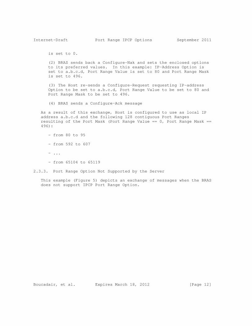
(2) BRAS sends back a Configure-Nak and sets the enclosed options to its preferred values. In this example: IP-Address Option is set to a.b.c.d, Port Range Value is set to 80 and Port Range Mask is set to 496.
(3) The Host re-sends a Configure-Request requesting IP-address Option to be set to a.b.c.d, Port Range Value to be set to 80 and Port Range Mask to be set to 496.
(4) BRAS sends a Configure-Ack message
As a result of this exchange, Host is configured to use as local IP address a.b.c.d and the following 128 contiguous Port Ranges resulting of the Port Mask (Port Range Value == 0, Port Range Mask == 496):
- from 80 to 95
- from 592 to 607
- ...
- from 65104 to 65119
2.3.3. Port Range Option Not Supported by the Server
This example (Figure 5) depicts an exchange of messages when the BRAS does not support IPCP Port Range Option.
Boucadair, et al. Expires March 18, 2012 [Page 12]

Internet-Draft Port Range IPCP Options September 2011
+-----+ +-----+ | Host| | BRAS| +-----+ +-----+ | | | (1) IPCP Configure-Request | | IP ADDRESS=0.0.0.0 | | PORT RANGE VALUE=0 | | PORT RANGE MASK=0 | |===============================================>| | | | (2) IPCP Configure-Reject | | PORT RANGE VALUE=0 | | PORT RANGE MASK=0 | |<===============================================| | | | (3) IPCP Configure-Request | | IP ADDRESS=0.0.0.0 | |===============================================>| | | | (4) IPCP Configure-Nak | | IP ADDRESS=a.b.c.d | |<===============================================| | | | (5) IPCP Configure-Request | | IP ADDRESS=a.b.c.d | |===============================================>| | | | (6) IPCP Configure-Ack | | IP ADDRESS=a.b.c.d | |<===============================================| | |
Figure 5: Failed flow: Port Range Option not supported by the server
The main steps of this flow are listed hereafter:
(1) The Host sends a first Configure-Request which includes the set of options it desires to negotiate. All these Configuration Options are negotiated simultaneously. In this example, Configure-Request carries the codes of IP-address, Port Range Value and Port Range Mask options. In this example, IP-address Option is set to 0.0.0.0, Port Range Value is set to 0 and Port Range Mask is set to 0.
(2) BRAS sends back a Configure-Reject to decline Port Range option.
Boucadair, et al. Expires March 18, 2012 [Page 13]

Internet-Draft Port Range IPCP Options September 2011
(3) The Host sends a Configure-Request which includes only the codes of IP-Address option. In this example, IP-Address Option is set to 0.0.0.0.
(4) BRAS sends back a Configure-Nak and sets the enclosed option to its preferred value. In this example: IP-Address Option is set to a.b.c.d.
(5) The Host re-sends a Configure-Request requesting IP-Address Option to be set to a.b.c.d.
(6) BRAS sends a Configure-Ack message.
As a result of this exchange, Host is configured to use as local IP address a.b.c.d. This IP address is not a shared IP address.
2.3.4. Port Range Option not Supported by the Client
This example (Figure 6) depicts exchanges when only shared IP addresses are assigned to end-user’s devices. The server is configured to assign only shared IP addresses. If Port Range Options are not enclosed in the configuration request, the request is rejected and the requesting peer will be unable to access the service as depicted in Figure 6.
+-----+ +-----+ | Host| | BRAS| +-----+ +-----+ | | | (1) IPCP Configure-Request | | IP ADDRESS=0.0.0.0 | |===============================================>| | | | (2) IPCP Protocol-Reject | |<===============================================| | |
Figure 6: Port Range Option not supported by the Client
The main steps of this flow are:
(1) The Host sends a Configure-Request requesting IP-Address Option to be set to 0.0.0.0 and without enclosing the Port Range Option.
Boucadair, et al. Expires March 18, 2012 [Page 14]

Internet-Draft Port Range IPCP Options September 2011
(2) BRAS sends a Protocol-Reject message.
As a result of this exchange, Host is not able to access the service.
3. IANA Considerations
No action is required from IANA since this document adheres to [RFC2153].
4. Security Considerations
This document does not introduce any security issue in addition to those related to PPP. Service providers should use authentication mechanisms such as CHAP [RFC1994] or PPP link encryption [RFC1968].
The use of small and non-random port range may increase host exposure to attacks described in [RFC6056]. This risk can be reduced by using larger port ranges, by using Random Port Range Option or by activating means to improve the robustness of TCP against Blind In- Window Attacks [RFC5961].
5. Contributors
Jean-Luc Grimault and Alain Villefranque contributed to this document.
6. Acknowledgements
The authors would like to thank C. Jacquenet, J. Carlson, B. Carpenter, M. Townsley and J. Arkko for their review.
7. References
7.1. Normative References
[RFC1661] Simpson, W., "The Point-to-Point Protocol (PPP)", STD 51, RFC 1661, July 1994.
[RFC1968] Meyer, G. and K. Fox, "The PPP Encryption Control Protocol (ECP)", RFC 1968, June 1996.
[RFC1994] Simpson, W., "PPP Challenge Handshake Authentication Protocol (CHAP)", RFC 1994, August 1996.
Boucadair, et al. Expires March 18, 2012 [Page 15]

Internet-Draft Port Range IPCP Options September 2011
[RFC2119] Bradner, S., "Key words for use in RFCs to Indicate Requirement Levels", BCP 14, RFC 2119, March 1997.
[RFC2153] Simpson, W. and K. Fox, "PPP Vendor Extensions", RFC 2153, May 1997.
[RFC5961] Ramaiah, A., Stewart, R., and M. Dalal, "Improving TCP’s Robustness to Blind In-Window Attacks", RFC 5961, August 2010.
7.2. Informative References
[CIPHERS] Black, J. and P. Rogaway, "Ciphers with Arbitrary Finite Domains Topics in Cryptology", 2002, < CT-RSA 2002, Lecture Notes in Computer Science vol. 2271>.
[I-D.boucadair-port-range] Boucadair, M., Levis, P., Bajko, G., and T. Savolainen, "IPv4 Connectivity Access in the Context of IPv4 Address Exhaustion: Port Range based IP Architecture", draft-boucadair-port-range-02 (work in progress), July 2009.
[I-D.despres-sam] Despres, R., "Scalable Multihoming across IPv6 Local- Address Routing Zones Global-Prefix/Local-Address Stateless Address Mapping (SAM)", draft-despres-sam-03 (work in progress), July 2009.
[I-D.ietf-behave-lsn-requirements] Perreault, S., Yamagata, I., Miyakawa, S., Nakagawa, A., and H. Ashida, "Common requirements for Carrier Grade NAT (CGN)", draft-ietf-behave-lsn-requirements-03 (work in progress), August 2011.
[RFC6056] Larsen, M. and F. Gont, "Recommendations for Transport- Protocol Port Randomization", BCP 156, RFC 6056, January 2011.
[RFC6269] Ford, M., Boucadair, M., Durand, A., Levis, P., and P. Roberts, "Issues with IP Address Sharing", RFC 6269, June 2011.
[RFC6346] Bush, R., "The Address plus Port (A+P) Approach to the IPv4 Address Shortage", RFC 6346, August 2011.
Boucadair, et al. Expires March 18, 2012 [Page 16]

Internet-Draft Port Range IPCP Options September 2011
Authors’ Addresses
Mohamed Boucadair France Telecom Rennes 35000 France
Email: [email protected]
Pierre Levis France Telecom Caen France
Email: [email protected]
Gabor Bajko Nokia
Email: gabor(dot)bajko(at)nokia(dot)com
Teemu Savolainen Nokia
Email: [email protected]
Tina Tsou Huawei Technologies (USA) 2330 Central Expressway Santa Clara, CA 95050 USA
Phone: +1 408 330 4424 Email: [email protected]
Boucadair, et al. Expires March 18, 2012 [Page 17]


Network Working Group R. Bush, Ed.Internet-Draft Internet Initiative JapanIntended status: Experimental May 31, 2011Expires: December 2, 2011
The A+P Approach to the IPv4 Address Shortage draft-ymbk-aplusp-10
Abstract
We are facing the exhaustion of the IANA IPv4 free IP address pool. Unfortunately, IPv6 is not yet deployed widely enough to fully replace IPv4, and it is unrealistic to expect that this is going to change before the depletion of IPv4 addresses. Letting hosts seamlessly communicate in an IPv4-world without assigning a unique globally routable IPv4 address to each of them is a challenging problem.
This draft proposes an IPv4 address sharing scheme, treating some of the port number bits as part of an extended IPv4 address (Address plus Port, or A+P). Instead of assigning a single IPv4 address to a single customer device, we propose to extend the address field by using bits from the port number range in the TCP/UDP header as additional end point identifiers, thus leaving a reduced range of ports available to applications. This means assigning the same IPv4 address to multiple clients (e.g., CPE, mobile phones), each with its assigned port-range. In the face of IPv4 address exhaustion, the need for addresses is stronger than the need to be able to address thousands of applications on a single host. If address translation is needed, the end-user should be in control of the translation process - not some smart boxes in the core.
Requirements Language
The key words "MUST", "MUST NOT", "REQUIRED", "SHALL", "SHALL NOT", "SHOULD", "SHOULD NOT", "RECOMMENDED", "MAY", and "OPTIONAL" in this document are to be interpreted as described in RFC 2119 [RFC2119].
Status of this Memo
This Internet-Draft is submitted in full conformance with the provisions of BCP 78 and BCP 79.
Internet-Drafts are working documents of the Internet Engineering Task Force (IETF). Note that other groups may also distribute working documents as Internet-Drafts. The list of current Internet- Drafts is at http://datatracker.ietf.org/drafts/current/.
Bush Expires December 2, 2011 [Page 1]

Internet-Draft A+P Addressing Extension May 2011
Internet-Drafts are draft documents valid for a maximum of six months and may be updated, replaced, or obsoleted by other documents at any time. It is inappropriate to use Internet-Drafts as reference material or to cite them other than as "work in progress."
This Internet-Draft will expire on December 2, 2011.
Copyright Notice
Copyright (c) 2011 IETF Trust and the persons identified as the document authors. All rights reserved.
This document is subject to BCP 78 and the IETF Trust’s Legal Provisions Relating to IETF Documents (http://trustee.ietf.org/license-info) in effect on the date of publication of this document. Please review these documents carefully, as they describe your rights and restrictions with respect to this document. Code Components extracted from this document must include Simplified BSD License text as described in Section 4.e of the Trust Legal Provisions and are provided without warranty as described in the Simplified BSD License.
Bush Expires December 2, 2011 [Page 2]

Internet-Draft A+P Addressing Extension May 2011
Table of Contents
1. Introduction . . . . . . . . . . . . . . . . . . . . . . . . . 4 1.1. Problems with Carrier Grade NATs . . . . . . . . . . . . . 4 2. Terminology . . . . . . . . . . . . . . . . . . . . . . . . . 5 3. Design Constraints and Functions . . . . . . . . . . . . . . . 6 3.1. Design Constraints . . . . . . . . . . . . . . . . . . . . 6 3.2. A+P Functions . . . . . . . . . . . . . . . . . . . . . . 7 3.3. Overview of the A+P Solution . . . . . . . . . . . . . . . 8 3.3.1. Signaling . . . . . . . . . . . . . . . . . . . . . . 9 3.3.2. Address Realm . . . . . . . . . . . . . . . . . . . . 11 3.3.3. Reasons for Allowing Multiple A+P Gateways . . . . . . 15 3.3.4. Overall A+P Architecture . . . . . . . . . . . . . . . 17 3.4. A+P experiments . . . . . . . . . . . . . . . . . . . . . 17 4. Stateless A+P Mapping Function . . . . . . . . . . . . . . . . 18 4.1. Stateless A+P Mapping gateway (SMAP) Function description . . . . . . . . . . . . . . . . . . . . . . . 18 4.2. Implementation Mode . . . . . . . . . . . . . . . . . . . 20 4.3. Towards IPv6-only Networks . . . . . . . . . . . . . . . . 22 4.4. PRR: On Stateless and Binding Table Modes . . . . . . . . 22 4.5. General recommendations on SMAP . . . . . . . . . . . . . 23 5. Deployment Scenarios . . . . . . . . . . . . . . . . . . . . . 24 5.1. A+P Deployment Models . . . . . . . . . . . . . . . . . . 24 5.1.1. A+P for Broadband Providers . . . . . . . . . . . . . 24 5.1.2. A+P for Mobile Providers . . . . . . . . . . . . . . . 24 5.1.3. A+P from the Provider Network Perspective . . . . . . 25 5.2. Dynamic Allocation of Port Ranges . . . . . . . . . . . . 27 5.3. Example of A+P-forwarded Packets . . . . . . . . . . . . . 28 5.3.1. Forwarding of Standard Packets . . . . . . . . . . . . 33 5.3.2. Handling ICMP . . . . . . . . . . . . . . . . . . . . 33 5.3.3. Fragmentation . . . . . . . . . . . . . . . . . . . . 34 5.3.4. Limitations of the A+P approach . . . . . . . . . . . 34 5.3.5. Port allocation strategy agnostic . . . . . . . . . . 35 6. IANA Considerations . . . . . . . . . . . . . . . . . . . . . 35 7. Security Considerations . . . . . . . . . . . . . . . . . . . 35 8. Authors . . . . . . . . . . . . . . . . . . . . . . . . . . . 36 9. Acknowledgments . . . . . . . . . . . . . . . . . . . . . . . 37 10. References . . . . . . . . . . . . . . . . . . . . . . . . . . 38 10.1. Normative References . . . . . . . . . . . . . . . . . . . 38 10.2. Informative References . . . . . . . . . . . . . . . . . . 38 Author’s Address . . . . . . . . . . . . . . . . . . . . . . . . . 40
Bush Expires December 2, 2011 [Page 3]

Internet-Draft A+P Addressing Extension May 2011
1. Introduction
This document describes a technique to deal with the imminent IPv4 address space exhaustion. Many large Internet Service Providers (ISPs) face the problem that their networks’ customer edges are so large that it will soon not be possible to provide each customer with a unique public IPv4 address. Therefore, although undesirable, address sharing, in the same molds as NAT, is inevitable.
To allow end-to-end connectivity between IPv4 speaking applications we propose to extend the semantics of the IPv4 address with bits from the UDP/TCP header. Assuming we could limit the applications’ port addressing to any number of bits lower than 16, we can increase the effective size of an IPv4 address by remaining additional bits of up to 16. In this scenario, 1 to 65536 customers could be multiplexed on the same IPv4 address, while allowing them a fixed or dynamic range of 1 to 65536 ports. Customers could for example receive initial fixed port range, defined by operator and dynamically request additional blocks, depending on their contract. We call this "extended addressing" or "A+P" (Address plus Port) addressing. The main advantage of A+P is that it preserves the Internet "end-to-end" paradigm by not requiring translation (at least for some ports) of an IP address.
1.1. Problems with Carrier Grade NATs
Various forms of NATs will be installed at various levels and places in the IPv4-Internet to achieve address compression. This document argues for mechanisms where this happens as close to the edge of the network as possible, thereby minimizing damage to the End-to-End Principle and allowing end-customers to retain control over the address and port translation. Therefore it is essential to create mechanisms to "bypass" NATs in the core when applicable and keep the control at the end-user.
With Carrier Grade NATs in the core of the network the user is trapped behind unchangeable application policies, and the deployment of new applications is hindered by the need to implement the corresponding Application Level Gateways (ALGs) on the CGNs. This is the opposite of the "end-to-end" model of the Internet.
With the smarts at the edges, one can easily deploy new applications between consenting end-points by merely tweaking the NATs at the corresponding Customer Premises Equipment (CPE), or even upgrading them to a new version that supports a specific ALG.
Today’s NATs are typically mitigated by offering the customers limited control over them, e.g. port forwarding or UPnP/NAT-PMP.
Bush Expires December 2, 2011 [Page 4]

Internet-Draft A+P Addressing Extension May 2011
However, this is not expected to work with CGNs. CGN proposals - other than DS-Lite [I-D.ietf-softwire-dual-stack-lite] with A+P or PCP [I-D.ietf-pcp-base]- admit that it is not expected that applications that require specific port assignment or port mapping from the NAT box will keep working.
Another issue with CGN is the trade-off between session state and network placement. The furthest from the edge the CGN placed, the more session state needs to be kept due to larger subscriber aggregation, and more disruption in the case of a failure. In order to reduce the state, CGNs would end up somewhere closer to the edge. The CGN hence trades scalability for the amount of state that needs to be kept, which makes optimally placing a CGN a hard engineering problem
In some deployment scenarios, CGN can be seen as single point of failure and therefore the availability of delivered services are impacted by the ones of CGN s devices. Means to ensure state synchronisation and failover would be required to allow for service continuity whenever a failure occurs.
Intra-domain paths may not be optimal for communications between two nodes connected to the same domain deploying CGNs, hence leading to path stretches.
2. Terminology
This document makes use of the following terms:
Public Realm: This realm contains only public routable IPv4 addresses. Packets in this realm are forwarded based on the destination IPv4 address
A+P Realm: This realm contains both public routable IPv4 and also A+P addresses.
A+P Packet: A regular IPv4 packet is forwarded based on the destination IPv4 address and the TCP/UDP port numbers.
Private Realm: This realm contains IPv4 addresses that are not globally routed. They may be taken from the [RFC1918] range. However, this document does not make such an assumption. We regard as private address space any IPv4 address, which needs to be translated in order to gain global connectivity, irrespective of whether it falls in [RFC1918] space or not.
Bush Expires December 2, 2011 [Page 5]

Internet-Draft A+P Addressing Extension May 2011
Port Range Router (PRR): A device that forwards A+P packets.
Customer Premises Equipment (CPE): cable/DSL modem.
Provider Edge Router (PE): Customer aggregation router
Provider Border Router (BR): Providers edge to other providers
Network Core Routers (Core): Provider routers which are not at the edges.
3. Design Constraints and Functions
The problem of address space shortage is first felt by providers with a very large end-user customer base, such as broadband providers and mobile service providers. Though the cases and requirements are slightly different, they share many commonalities. In the following we develop a set of overall design constraints for solutions addressing the IPv4 address shortage problem.
3.1. Design Constraints
We regard several constraints as important for our design:
1) End-to-End is under customer control: Customers shall have the ability to deploy new application protocols at will. IPv4 address shortage should not be a license to break the Internet’s end-to-end paradigm.
2) Backward compatibility: Approaches should be transparent to unaware users. Devices or existing applications should be able to work without modification. Emergence of new applications should not be limited.
3) Highly-scalable and minimal state core: Minimal state should be kept inside the ISP’s network. If the operator is rolling out A+P incrementally, it is understood there may be state in the core in the non-A+P part of such a roll-out.
4) Efficiency vs. complexity: Operators should have the flexibility to trade off port multiplexing efficiency and scalability and end-to-end transparency.
5) "Double-NAT" should be avoided: Multiple gateway devices might be present in a path, and once one has done some translation, those packets should not be re-translated.
Bush Expires December 2, 2011 [Page 6]

Internet-Draft A+P Addressing Extension May 2011
6) Legal traceability: ISPs must be able to provide the identity of a customer from the knowledge of the IPv4 public address and the port. This should have as low an impact as is reasonable on storage by the ISP. We assume that NATs on customer premises do not pose much of a problem, while provider NATs need to keep additional logs.
7) IPv6 deployment should be encouraged. NAT444 strongly biases the users to the deployment of RFC 1918 addressing.
Constraint 5 is important: while many techniques have been deployed to allow applications to work through a NAT, traversing cascaded NATs is crucial if NATs are being deployed in the core of a provider network.
3.2. A+P Functions
The A+P architecture can be split into three distinct functions: encaps/decaps, NAT, and signaling.
Encaps/decaps function: is used to forward port-restricted A+P- packets over intermediate legacy devices. The encapsulation function takes an IPv4 packet, looks up the IP and TCP/UDP headers, and puts the packet into the appropriate tunnel. The state needed to perform this action is comparable to a forwarding table. The decapsulation device SHOULD check if the source address and port of packets coming out of the tunnel are legitimate (e.g., see [BCP38]). Based on the result of such a check, the packet MAY be forwarded untranslated, it MAY be discarded or MAY be NATed. In this document we refer to a device that provides this encaps/decaps functionality as Port-Range- Router (PRR).
Network Address Translation (NAT) function: is used to connect legacy end-hosts. Unless upgraded, end-hosts or end-systems are not aware of A+P restrictions and therefore assume a full IP address. The NAT function performs any address or port translation, including Application Level Gateways (ALGs) whenever required. The state that has to be kept to implement this function is the mapping for which external addresses and ports have been mapped to which internal addresses and ports, just as in CPEs embedding NAT today. A subtle, but very important, difference should be noted here: the customer has control over the NATing process or might choose to "bypass" the NAT. If this is done, we call the NAT a large scale NAT (LSN). However, if the NAT that does NOT allow the customer to control the translation process, we refer to as a CGN.
Signaling function: is used in order to allow A+P-aware devices get to know which ports are assigned to be passed through untranslated
Bush Expires December 2, 2011 [Page 7]
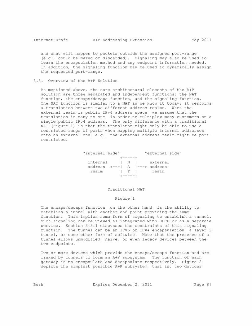
Internet-Draft A+P Addressing Extension May 2011
and what will happen to packets outside the assigned port-range (e.g., could be NATed or discarded). Signaling may also be used to learn the encapsulation method and any endpoint information needed. In addition, the signaling function may be used to dynamically assign the requested port-range.
3.3. Overview of the A+P Solution
As mentioned above, the core architectural elements of the A+P solution are three separated and independent functions: the NAT function, the encaps/decaps function, and the signaling function. The NAT function is similar to a NAT as we know it today: it performs a translation between two different address realms. When the external realm is public IPv4 address space, we assume that the translation is many-to-one, in order to multiplex many customers on a single public IPv4 address. The only difference with a traditional NAT (Figure 1) is that the translator might only be able to use a restricted range of ports when mapping multiple internal addresses onto an external one, e.g., the external address realm might be port- restricted.
"internal-side" "external-side" +-----+ internal | N | external address <---| A |---> address realm | T | realm +-----+
Traditional NAT
Figure 1
The encaps/decaps function, on the other hand, is the ability to establish a tunnel with another end-point providing the same function. This implies some form of signaling to establish a tunnel. Such signaling can be viewed as integrated with DHCP or as a separate service. Section 3.3.1 discusses the constraints of this signaling function. The tunnel can be an IPv6 or IPv4 encapsulation, a layer-2 tunnel, or some other form of softwire. Note that the presence of a tunnel allows unmodified, naive, or even legacy devices between the two endpoints.
Two or more devices which provide the encaps/decaps function and are linked by tunnels to form an A+P subsystem. The function of each gateway is to encapsulate and decapsulate respectively. Figure 2 depicts the simplest possible A+P subsystem, that is, two devices
Bush Expires December 2, 2011 [Page 8]

Internet-Draft A+P Addressing Extension May 2011
providing the encaps/decaps function.
+------------------------------------+ Private | +----------+ tunnel +----------+ | Public address --|-| gateway |==========| gateway |-|-- address realm | +----------+ +----------+ | realm +------------------------------------+ A+P subsystem
A simple A+P subsystem
Figure 2
Within an A+P subsystem, the public address realm is extended by using bits from the port number when forwarding packets. Each device is assigned one address from the external realm and a range of port numbers. Hence, devices which are part of an A+P subsystem can communicate with the public realm without the need for address translation (i.e., preserving end-to-end packet integrity): an A+P packet originated from within the A+P subsystem can be simply forwarded over tunnels up to the endpoint, where it gets decapsulated and routed in the external realm.
3.3.1. Signaling
The following information needs to be available on all the gateways in the A+P subsystem. It is expected that there will be a signaling protocols such as [I-D.bajko-pripaddrassign], [I-D.boucadair-dhcpv6-shared-address-option], [I-D.boucadair-pppext-portrange-option], or [I-D.ietf-pcp-base].
The information that needs to be shared is the following:
o a set of public IPv4 addresses,
o for each IPv4 address a starting point for the allocated port- range,
o number of delegated ports,
o optional key that enables partial or full preservation of entropy in port randomization - see [I-D.bajko-pripaddrassign],
o lifetime for each IPv4 address and allocated port-set,
Bush Expires December 2, 2011 [Page 9]

Internet-Draft A+P Addressing Extension May 2011
o the tunneling technology to be used (e.g., "IPv6-encapsulation")
o addresses of the tunnel endpoints (e.g., IPv6 address of tunnel endpoints)
o whether or not NAT function is provided by the gateway
o a device identification number and some authentication mechanisms
o a version number and some reserved bits for future use.
Note that the functions of encapsulation and decapsulation have been separated from the NAT function. However, to accommodate legacy hosts, NATing is likely to be provided at some point in the path; therefore the availability or absence of NATing MUST be communicated in signaling, as A+P is agnostic about NAT placement.
The port-ranges can be allocated in two different ways:
o If applications or end-hosts behind the CPE are not UPnPv2/NAT-PMP aware, then the CPE SHOULD request ports via mechanisms, e.g. as described in [I-D.bajko-pripaddrassign] and [I-D.boucadair-pppext-portrange-option]. Note that different port-ranges can have different lifetimes, and the CPE is not entitled to use them after they expire - unless it refreshes those ranges. It is up to the ISP to put mechanisms in place, that determine what percentage of already allocated port-ranges should be exhausted before a CPE may requests additional ranges, how often the CPE can request additional ranges, and so on. (To prevent Denial of Service attacks.)
o If applications behind the CPE are UPnPv2/NAT-PMP aware additional ports MAY be requested through that mechanism. In this case the CPE should forward those requests to the LSN and the LSN should reply reporting if the requested ports are available or not (and if they are not available some alternatives should be offered). Here again, to prevent potential denial of service attacks, mechanism should be in place to prevent UPnPv2/NAT-PMP packet storms and fast port allocation. Detailed description of this mechanism, called PCP is described in [I-D.ietf-pcp-base].
Whatever signaling mechanism is used inside the tunnels, DHCP, IPCP, or PCP-based, synchronization between signaling server and PRR must be established in both directions. For example, if we use DHCP as signaling mechanism, the PRR must communicate to DHCP server at least its IP range. The DHCP server then starts to allocate IPs and port- ranges to CPEs and communicates back to the PRR which IP and port range have been allocated to which CPE, so the PRR knows to which
Bush Expires December 2, 2011 [Page 10]

Internet-Draft A+P Addressing Extension May 2011
tunnel redirect incoming traffic. In addition, DHCP MUST also communicate lifetimes of port-ranges assigned to CPE via the PRR. DHCP server may be co-located with the PRR function to ease address management and also to avoid the need to introduce a communication protocol between the PRR and DHCP.
If UPnPv2/NAT-PMP is used as dynamic port allocation mechanism, the PRR must also communicate to the DHCP (or IPCP) server to avoid those ports. The PRR must somehow (DHCP or IPCP options) communicate back to CPE that allocation of ports was successful, so CPE adds those ports to existing port ranges.
Note that operation can be even simplified if a fixed length of port ranges are assigned to all customers and no differentiation is implemented based on port range length. In such case, the binding table maintained by the PRR can be dynamically built upon the receipt of a first packet form a port-restricted device.
3.3.2. Address Realm
Each gateway within the A+P subsystem manages a certain portion of A+P address space, that is, a portion of IPv4 space which is extended by borrowing bits from the port number. This address space may be a single, port-restricted IPv4 address. The gateway MAY use its managed A+P address space for several purposes:
o Allocation of a sub-portion of the A+P address space to other authenticated A+P gateways in the A+P subsystem (referred to as delegation). We call the allocated sub-portion delegated address space.
o Exchange of (untranslated) packets with the external address realm. For this to work, such packets MUST use source address and port belonging to the non-delegated address space.
If the gateway is also capable of performing the NAT function, it MAY translate packets arriving on an internal interface which are outside of its managed A+P address space into non-delegated address space.
Hence, a provider may have ’islands’ of A+P as they slowly deploy over time. The provider does not have to replace CPE until they want to provide the A+P function to an island of users or even to one particular user in a sea of non-A+P users.
An A+P gateway ("A"), accepts incoming connections from other A+P gateways ("B"). Upon connection establishment (provided appropriate authentication), B would "ask" A for delegation of an A+P address. In turn, A will inform B about its public IPv4 address, and will
Bush Expires December 2, 2011 [Page 11]

Internet-Draft A+P Addressing Extension May 2011
delegate a portion of its port-range to B. In addition, A will also negotiate the encaps/decaps function with B (e.g., let B know the address of the decaps device/other-end-point of the tunnel).
This could be implemented for example via a NAT-PMP or DHCP-like solution. In general the following rule applies: A sub-portion of the managed A+P address space is delegated as long as devices below ask for it, otherwise private IPv4 is provided to support legacy hosts.
In the following example, IPv4 address reserved for documentation blocks defined in [RFC5737] are used.
private +-----+ +-----+ public address ---| B |==========| A |--- Internet realm +-----+ +-----+
Address space realm of A: public IPv4 address = 192.0.2.1 port range = 0-65535
Address space realm of B: public IPv4 address = 192.0.2.1 port range = 2560-3071
Configuration example
Figure 3
Figure 3 illustrates a sample configuration. Note that A might actually consist of three different devices: one that handles signaling requests from B; one device that performs encapsulation and decapsulation; and, if provided, one device that performs NATing function (e.g., LSN). Packet forwarding is assumed to be as follows: In the "out-bound" case, a packet arrives from the private address realm to B. As stated above, B has two options: it can either apply or not apply the NAT function. The decision depends upon the specific configuration and/or the capabilities of A and B. Note that NAT functionality is required to support legacy hosts, however, this can be done at either of the two devices A or B. The term NAT refers to translating the packet into the managed A+P address (B has address 192.0.2.1 and ports 2560-3071 in the example above). We then have two options:
Bush Expires December 2, 2011 [Page 12]

Internet-Draft A+P Addressing Extension May 2011
1) B NATs the packet. The translated packet is then tunneled to A. A recognizes that the packet has already been translated, because the source address and port match the delegated space. A decapsulates the packet and releases it in the public Internet.
2) B does not NAT the packet. The untranslated packet is then tunneled to A. A recognizes that the packet has not been translated, so A forwards the packet to a co-located NATing device, which translates the packet and routes it in the public Internet. This device, e.g. - an LSN, has to store the mapping between the source port used to NAT and the tunnel where the packet came from, in order to correctly route the reply. Note that A cannot use a port number from the range that has been delegated to B. As a consequence A has to assign a part of its non-delegated address space to the NATing function.
"Inbound" packets are handled in the following way: a packet from the public realm arrives at A. A analyzes the destination port number to understand whether the packet needs to be NATed or not.
1) If the destination port number belongs to the range that A delegated to B, then A tunnels the packet to B. B NATs the packet using its stored mapping and forwards the translated packet to the private domain.
2) If the destination port number is from the address space of the LSN, then A passes the packet on to the co-located LSN which uses its stored mapping to NAT the packet into the private address realm of B. The appropriate tunnel is stored as well in the mapping of the initial NAT. The LSN then encapsulates the packet to B, which decapsulates it and normally routes it within its private realm.
3) Finally, if the destination port number neither falls in a delegated range, nor into the address range of the LSN, A discards the packet. If the packet is passed to the LSN, but no mapping can be found, the LSN discards the packet.
Observe that A must be able to receive all IPv4 packets destined to the public IPv4 address (192.0.2.1 in the example), so that it can make routing decisions according to the port number. On the other hand, B receives IPv4 packets destined to the public IPv4 address only via the established tunnel with A. In other words, B uses the public IPv4 address just for translation purposes, but it is not used to make routing decisions. This allows us to keep the routing logic at B as simple as described above, while enabling seamless communication between A+P devices sharing the same public IPv4 address.
Bush Expires December 2, 2011 [Page 13]

Internet-Draft A+P Addressing Extension May 2011
private +-----+ +-----+ public address ---| B |==========| A |--- Internet realm 1 +-----+ +-----+ | private +-----+ | address ---| C |============/ realm 2 +-----+
Address space realm of A: public IPv4 address = 192.0.2.1 port range = 0-65535
Address space realm of B: public IPv4 address = 192.0.2.1 port range = 2560-3071
Address space realm of C: public IPv4 address = 192.0.2.1 port range = 0-2559
Hierarchical A+P
Figure 4
Consider the example shown in Figure 4. Here both B and C use the encaps/decaps function to establish a tunnel with A, and they are assigned the same public IPv4 address with different, non-overlapping port-ranges. Assume that a host in B’s private realm sends a packet destined to address 192.0.2.1 and port 2000, and that B has been instructed to NAT all packets destined to 192.0.2.1. Under these assumptions, B receives the packet and NATs it using its own public IPv4 address (192.0.2.1) and a port selected from its configured port-range (e.g., 3000). B then tunnels the translated packet to A. When A receives the packet via the tunnel, it looks at the destination address and port, recognizes C’s delegated range, and then tunnels the packet to C. Observe that, apart from stripping the tunnel header, A handles the packet as if it came from the public Internet. When C receives the packet, it NATs the destination address into one address chosen from its private address realm, while keeping the source address (192.0.2.1) and port (3000) untranslated. Return traffic is handled the same way. Such a mechanism allows hosts behind A+P devices to communicate seamlessly even when they share the same public IPv4 address.
Please refer to Section 4 for a discussion of an alternative A+P mechanism that does not incur in path stretches penalties for intra- domain communication.
Bush Expires December 2, 2011 [Page 14]

Internet-Draft A+P Addressing Extension May 2011
3.3.3. Reasons for Allowing Multiple A+P Gateways
Since each device in an A+P subsystem provides the encaps/decaps function, new devices can establish tunnels and become in turn part of an A+P subsystem. As noted above, being part of an A+P subsystem implies the capability of talking to the external address realm without any translation. In particular, as described in the previous section, a device X in an A+P subsystem can be reached from the external domain by simply using the public IPv4 address and a port which has been delegated to X. Figure 5 shows an example where three devices are connected in a chain. In other words, A+P signaling can be used to extend end-to-end connectivity to the devices which are in an A+P subsystem. This allows A+P-aware applications (or OSes) running on end hosts to enter an A+P subsystem and exploit untranslated connectivity.
There are two modes for end-hosts to gain fine-grained control of end-to-end connectivity. The first is where actual end-hosts perform the NAT function and the encaps/decaps function which is required to join the A+P subsystem. This option works in a similar way to the NAT-in-the-host trick employed by virtualization software such as VMware, where the guest operating system is connected via a NAT to the host operating system. The second mode is applications which autonomously ask for an A+P address and use it to join the A+P subsystem. This capability is necessary for some applications that require end-to-end connectivity (e.g., applications that need to be contacted from outside).
+---------+ +---------+ +---------+ internal | gateway | | gateway | | gateway | external realm --| 1 |======| 2 |======| 3 |-- realm +---------+ +---------+ +---------+
An A+P subsystem with multiple devices
Figure 5
Whatever the reasons might be, the Internet was built on a paradigm that end-to-end connectivity is important. A+P makes this still possible in a time where address shortage forces ISPs to use NATs at various levels. In such sense, A+P can be regarded as a way to bypass NATs.
Bush Expires December 2, 2011 [Page 15]

Internet-Draft A+P Addressing Extension May 2011
+---+ (customer2) |A+P|-. +---+ +---+ \ NAT|A+P|-. \ +---+ | \ | forward if in-range +---+ \+---+ +---+ / |A+P|------|A+P|----|A+P|---- +---+ /+---+ +---+ \ / NAT if necessary / (cust1) (prov. (e.g., provider NAT) +---+ / router) |A+P|-’ +---+
A complex A+P subsystem
Figure 6
Figure 6 depicts a complex scenario, where the A+P subsystem is composed by multiple devices organized in a hierarchy. Each A+P gateway decapsulates the packet and then re-encapsulates it again to the next tunnel.
A packet can either be NATed when it enters the A+P subsystem, or at intermediate devices, or when it exits the A+P subsystem. This could be for example a gateway installed within the provider’s network, together with a LSN. Then each customer operates its own CPE. However, behind the CPE applications might also be A+P-aware and run their own A+P-gateways, which enables them to have end-to-end connectivity.
One limitation applies, if "delayed translation" is used (e.g., translation at the LSN instead of the CPE). If devices using "delayed translation" want to talk to each other they SHOULD use A+P addresses or out-of-band addressing.
Bush Expires December 2, 2011 [Page 16]

Internet-Draft A+P Addressing Extension May 2011
3.3.4. Overall A+P Architecture
A+P architecture
IPv4 Full-A+P AFTR CGN | | | | <-- Full IPv4 ---- Port range ---- Port range ---- Provider ---> allocated & dynamic & LSN NAT ONLY allocation (NAT on CPE (No mechanism) (no NAT) (NAT on CPE) and on LSN) for customer to bypass CGN)
Figure 7: A+P overall architecture
The A+P architecture defines various deployment options within an ISP. Figure 7 shows the spectrum of deployment options. On the far left is the common deployment method for broadband subscribers today, an IPv4 address unrestricted with full port-range. Full-A+P refers to a port-range allocation from the ISP. The customer must operate an A+P-aware CPE device and no NATing functionality is provided by the ISP. AFTR, such as DS-Lite [I-D.ietf-softwire-dual-stack-lite], is a hybrid. There is NAT present in the core (in this document referred to as LSN), but the user has the option to "bypass" that NAT in one form or an other, for example via A+P, NAT-PMP, etc... Finally, a service provider which only deploys CGN, will place a NAT in the providers core and does not allow the customer to "bypass" the translation process or modify ALGs on the NAT. The customer is provider-locked. Notice that all options (besides full IPv4) require some form of tunneling mechanism (e.g., 4in6) and a signaling mechanism (see Section 3.3.1).
3.4. A+P experiments
There are implementations of A+P as well as documented experiments. France Telecom did experiments, that are described in [I-D.deng-aplusp-experiment-results]. As seen in that experiment, most tested applications are unaffected. There are problems with torrent protocol and applications, as listening port is out of A+P port range and some UPnP may be required to make it work with A+P
Problems with BitTorrent have already been experienced in the wild by users trapped behind a non-UPnP-capable CPE. The current workaround for the end user is to statically map ports, which can be done in the A+P scenario as well.
Bittorrent tests and experiments in shared IP and port range
Bush Expires December 2, 2011 [Page 17]

Internet-Draft A+P Addressing Extension May 2011
environments are well described in [I-D.boucadair-behave-bittorrent-portrange]. Conclusions in that document tell us that two limitations were experienced. The first occurred when two clients sharing the same IP address tried to simultaneously retrieve the SAME file located in a SINGLE remote peer. The second limitation occured when a client tried to download a file located on several seeders, when those seeders shared the same IP address. Mutual file sharing between hosts having the same IP address has been checked. Indeed, machines having the same IP address can share files with no alteration compared to current IP architectures.
Working implementations of A+P can be found in ISC AFTR (http://www.isc.org/software/aftr), FT Orange opensource A+P (http://opensourceaplusp.weebly.com/) and 4RD from ipinfusion.com (stateless A+P).
4. Stateless A+P Mapping Function
4.1. Stateless A+P Mapping gateway (SMAP) Function description
SMAP stands for Stateless A+P Mapping. This function is responsible to encapsulate (Resp., decapsulate), in a stateless scheme, IPv4 packets in (Resp. from) IPv6 ones. A SMAP function may be hosted in a PRR, end-user device, etc.
As mentioned in Section 4.1 of [RFC6052], the suffix part may enclose the port.
Stateless A+P Mapping gateway (SMAP) consists in two basic functions as described in Figure 8.
1. SMAP encapsulates an IPv4 packet, destined to a shared IPv4 address, in IPv6 one. The IPv6 source address is constructed using an IPv4-Embedded IPv6 address [RFC6052] from the IPv4 source address and port number plus the IPv6 prefix which has been provisioned to the node performing the SMAP function. The destination IPv6 address is constructed using the shared IPv4 destination address and port number plus the IPv6 prefix which has been provisioned to the SMAP function and which is dedicated to IPv4 destination addresses.
2. SMAP extracts IPv4 incoming packets from IPv6 incoming ones which have IPv6 source addresses belonging to the prefix of the node performing the SMAP function. Extracted IPv4 packets are then forwarded to the point identified by the IPv4 destination address and port number.
Bush Expires December 2, 2011 [Page 18]

Internet-Draft A+P Addressing Extension May 2011
+-------------------+ | |----IPv6---\ ----IPv4---\| |----IPv4---\\ -----------/| |-----------// | |-----------/ | SMAP | | | /--IPv6----- /---IPv4----| |//---IPv4---- \-----------| |\\----------- | | \----------- +-------------------+
Figure 8: Stateless A+P Mapping Gateway Function
A SMAP-enabled node will perform the stateless 6/4 mapping function for all public shared IPv4 addresses for which it was designated as a stateless 6/4 mapping gateway.
To perform stateless 6/4 mapping function a SMAP gateway must:
o be provided with an IPv6 prefix (i.e., Pref6). The SMAP gateway uses this prefix to construct IPv6 source addresses for all IPv4 shared addresses for which it was designated as a SMAP gateway. The IPv6 prefix may be provisioned statically or dynamically (e.g., DHCP)
o be able to know the IPv6 prefix of the node serving as another SMAP gateway for IPv4 destination addresses. This prefix may be known in various ways:
* Default or Well Known Prefix (i.e., 64:ff9b::/96) which was provisioned statically or dynamically;
* Retained at the reception of incoming IPv4-in-IPv6 encapsulated packets;
* Discovered at the communication starting thanks to mechanisms as DNS resolution for example.
When the SMAP-enabled node receives IPv4 packets with IPv4 source addresses for which it was not designated as a SMAP gateway, it will not perform stateless 6/4 mapping function for those packets. Those packets will be handled in a classical way (i.e., forwarded, dropped or locally processed).
When the SMAP-enabled node receives IPv6 packets with IPv6 addresses which do not match with its IPv6 prefix, it will not perform the
Bush Expires December 2, 2011 [Page 19]

Internet-Draft A+P Addressing Extension May 2011
stateless 6/4 mapping function for those packets. Those packets will be handled in a classical way (i.e., forwarded, dropped or locally processed).
4.2. Implementation Mode
In this configuration, the node A performs the stateless mapping function on the received IPv4 traffic (encapsulated in IPv6 packets) before forwarding to the node B. The node B performs the stateless mapping function on the received IPv6 traffics (extracting IPv4 packets) before forwarding the IPv4 traffic to the destination identified by the IPv4 destination address and port number. In the opposite direction and as previously, the node B performs the stateless mapping function on the received IPv4 traffics (encapsulating in IPv6 packets) before forwarding to the node A. The node A performs the stateless mapping function on the received IPv6 traffic (extracting IPv4 packets) before forwarding the IPv4 traffic to the point identified by the IPv4 destination address and port number. In this case, only IPv6 traffic is managed in the network segment between the nodes A and B.
+------+ +------+ | |----IPv6---\ | | ----IPv4---\| |----IPv4---\\| |----IPv4---\ -----------/| |-----------//| |-----------/ | |-----------/ | | | SMAP | | SMAP | | | /----IPv6---| | /---IPv4----| |//---IPv4----| |/---IPv4---- \-----------| |\\-----------| |\----------- | | \-----------| | +------+ +------+ node A node B
Figure 9
Several deployment scenarios of the SMAP function may be envisaged in the context of Port Range based solutions:
o A SMAP function is embedded in a port-restricted device. Other SMAP-enabled nodes are deployed in the boundaries between IPv6- enabled realms and IPv4 ones. This scenario may be particularly deployed for intra-domain communications so as to interconnect heterogeneous realms (i.e., IPv6/IPv4) within the same AS.
o A SMAP function is embedded in a port-restricted device. Other
Bush Expires December 2, 2011 [Page 20]

Internet-Draft A+P Addressing Extension May 2011
SMAP-enabled nodes are deployed in the interconnection segment (with adjacent IPv4-only ones) of a given AS. This deployment scenario is more suitable for service providers targeting the deployment of IPv6 since it eases the migration to full IPv6. Core nodes are not required to activate anymore both IPv4 and IPv6 transfer capabilities.
Other considerations regarding the interconnection of SMAP-enabled domains should be elaborated. The following provides a non exhaustive list of interconnection schemes.
o The interconnection of two domains implementing the SMAP function may be deployed via IPv4 Internet (Figure 10): This means that IPv4 packets encapsulated in IPv6 one are transferred using IPv6 until reaching the first SMAP-node. Then these packets are de- encapsulated and are forwarded using IPv4 transfer capabilities. A remote SMAP-enabled node will receive those packets and proceeds to an IPv4-in-IPv6 encapsulation. These packets are then routed normally until reaching the port-restricted devices which de- encapsulates the packets.
+------+ +------+ +--------+ +------+ +------+ | |--IPv6--\ | | | | | |---IPv6--\ | | | |--IPv4--\\| |---|-IPv4---|--\| |---IPv4--\\| | | |--------//| |---|--------|--/| |---------//| | | |--------/ | | |Internet| | |---------/ | | | SMAP | | SMAP | | IPv4 | | SMAP | | SMAP | | | /--IPv6--| | | | | | /---IPv6--| | | |//--IPv4--| |/--|-IPv4---|---| |//--IPv4---| | | |\\--------| |\--|--------|---| |\\---------| | | | \--------| | | | | | \---------| | +------+ +------+ +--------+ +------+ +------+ Source node A node B Destination
Figure 10: Interconnection Scenario 1
o A second scheme is to interconnect two realms implementing the SMAP function using IPv6 (Figure 11). An IPv6 prefix (i.e., Pref6) assigned by IANA is used for this service. If appropriate routing configuration have been enforced, then the IPv6 encapsulated packets will be routed until the final destination. In order to implement this model, IPv4-inferred IPv6 prefixes are required to be injected in the IPv6 inter-domain routing tables.
Bush Expires December 2, 2011 [Page 21]

Internet-Draft A+P Addressing Extension May 2011
+------+ +------------+ +------+ | | | | | | | |----IPv6-----|----IPv6----|----IPv6----\ | | | |----IPv4-----|------------|----IPv4----\\| | | |-------------|------------|------------//| | | |-------------|------------|------------/ | | | SMAP | | Internet v6| | SMAP | | | /-----IPv6--|------------|-----IPv6-----| | | |//---IPv4----|------------|-------IPv4---| | | |\\-----------|------------|--------------| | | | \-----------|------------|--------------| | | | | | | | +------+ +------------+ +------+ Source Destination
Figure 11: Interconnection Scenario 2
4.3. Towards IPv6-only Networks
The deployment of SMAP function allows for smooth migration of networks to IPv6-only scheme while maintaining the delivery of IPv4 connectivity services to customers. The delivery of IPv4 connectivity services over an IPv6-only network does not require any stateful function to be deployed on the core network. Owing to this A+P mode, both the IPv4 service continuity and migration to an IPv6- only deployment model are facilitated.
4.4. PRR: On Stateless and Binding Table Modes
SMAP section discusses two modes: the binding and the stateless modes. Dynamic port allocation is not a feature of the stateless mode but it is supported in the binding mode. In the binding mode, distinct external IPv4 addresses may be used but this is not recommended.
o Stateless Mode
Complete stateless mapping implies that the IPv4 address and the significant bits coding the port range are reflected inside the IPv6 prefix assigned to the port-restricted device. This can be achieved either by embedding the full IPv4 address and the significant bits in the IPv6 prefix or by applying an algorithmic approach. Two alternatives are offered when such a stateless mapping is to be enabled:
- either using the IPv6 prefix already used for native IPv6 traffic,
Bush Expires December 2, 2011 [Page 22]

Internet-Draft A+P Addressing Extension May 2011
- or provide two prefixes to the port-restricted device: one for the native IPv6 traffic and one for the IPv4 traffic.
Note that:
- Providing two IPv6 prefixes has the advantages of allowing a /64 prefix for the port-restricted device along with another prefix (e.g., a /56 or /64) for native IPv6 traffic. This alternative spares the service provider to relate the native IPv6 traffic addressing plan to the IPv4 addressing plan. The drawback is the burden to allocate two prefixes to each port-restricted device and to route them. In addition, an address selection issue may be encountered.
- Providing one prefix for both needs (e.g., a /56 or a /64) spares the service provider to handle two types of IPv6 prefix for the port- restricted device and in routing tables. But the drawback is that it somewhat links strongly the IPv4 addressing plan to the allocated IPv6 prefixes.
As mentioned in Section 4.1 of [RFC6052], the suffix part may enclose the port.
o Binding Table Mode
Another alternative is to assign a "normal" IPv6 prefix to the port- restricted device and to use a binding table, which can be hosted by a service node, to correlate the (shared IPv4 address, Port Range) with an IPv6 address part of the assigned IPv6 prefix. For scalability reasons, this table should be instantiated within PRR- enabled nodes which are close to the port-restricted devices. The number of required entries if hosted at interconnection segment would be equal to the amount of subscribed users (one per port-restricted device).
4.5. General recommendations on SMAP
If Stateless A+P Mapping (SMAP) type of implementation is deployed over intermediate IPv6-ONLY-capable devices, it is recommended that default-routes are configured and IPv4 routing table is not "leaked" into IPv6 routing table in terms to have reachability for the packets going towards the internet.
One of stateless A+P variants is 4RD [I-D.despres-intarea-4rd]
Bush Expires December 2, 2011 [Page 23]

Internet-Draft A+P Addressing Extension May 2011
5. Deployment Scenarios
5.1. A+P Deployment Models
5.1.1. A+P for Broadband Providers
Some large broadband providers will not have enough public IPv4 address space to provide every customer with a single IP. The natural solution is sharing a single IP address among many customers. Multiplexing customers is usually accomplished by allocating different port numbers to different customers somewhere within the network of the provider.
It is expected that, when the provider wishes to enable A+P for a customer or a range of customers, the CPE can be upgraded or replaced to support A+P encaps/decaps functionality. Ideally the CPE also provides NATing functionality. Further, it is expected that at least another component in the ISP network provides the corresponding A+P functionality, and hence is able to establish an A+P subsystem with the CPE. This device is referred to as A+P router or port-range router (PRR), and could be located close to PE routers. The core of the network MUST support the tunneling protocol (which SHOULD be IPv6, as per Constraint 7) but MAY be another tunneling technology when necessary. In addition, we do not wish to restrict any initiative of customers who might want to run an A+P-capable network on or behind their CPE. To satisfy both Constraints 1 and 2 unmodified legacy hosts should keep working seamlessly, while upgraded/new end-systems should be given the opportunity to exploit enhanced features.
5.1.2. A+P for Mobile Providers
In the case of mobile service provider the situation is slightly different. The A+P border is assumed to be the gateway (e.g., GGSN/ PDN GW of 3GPP, or ASN GW of WiMAX). The need to extend the address is not within the provider network, but on the edge between the mobile phone devices and the gateway. While desirable, IPv6 connectivity may or may not be provided.
For mobile providers we use the following terms and assumptions:
1. Provider Network (PN)
2. Gateway (GW)
3. Mobile Phone device (phone)
Bush Expires December 2, 2011 [Page 24]

Internet-Draft A+P Addressing Extension May 2011
4. Devices behind phone, e.g., laptop computer connecting via phone to Internet.
We expect that the gateway has a pool of IPv4 addresses and is always in the data-path of the packets. Transport between the gateway and phone devices is assumed to be an end-to-end layer-2 tunnel. We assume that phone as well as gateway can be upgraded to support A+P. However, some applications running on the phone or devices behind the phone (such as laptop computers connecting via the phone), are not expected to be upgraded. Again, while we do not expect that devices behind the phone will be A+P aware/upgraded we also do not want to hinder their evolution. In this sense the mobile phone would be comparable to the CPE in the broadband provider case; the gateway to the PRR/LSN box in the network of the broadband provider.
5.1.3. A+P from the Provider Network Perspective
ISPs suffering from IPv4 address space exhaustion are interested in achieving a high address space compression ratio. In this respect, an A+P subsystem allows much more flexibility than traditional NATs: the NAT can be placed at the customer, and/or in the provider network. In addition hosts or applications can request ports and thus have untranslated end-to-end connectivity.
+---------------------------+ private | +------+ A+P-in +-----+ | dual-stacked (RFC1918) --|-| CPE |==-IPv6-==| PRR |-|-- network space | +------+ tunnel +-----+ | (public addresses) | ^ +-----+ | | | IPv6-only | LSN | | | | network +-----+ | +----+----------------- ^ --+ | | on customer within provider premises and control network
A simple A+P subsystem example
Figure 12
Consider the deployment scenario in Figure 12, where an A+P subsystem is formed by the CPE and a PRR within the ISP core network, preferably close to the customer edge, and represents the border from where on packets are forwarded based on address and port. The provider MAY deploy a LSN co-located with the PRR to handle packets that have not been translated by the CPE. In such a configuration,
Bush Expires December 2, 2011 [Page 25]

Internet-Draft A+P Addressing Extension May 2011
the ISP allows the customer to freely decide whether the translation is done at the CPE or at the LSN. In order to establish the A+P subsystem, the CPE will be configured automatically (e.g. via a signaling protocol, that conforms to the requirements stated above).
Note that the CPE in the example above is only provisioned with an IPv6 address on the external interface.
+------------ IPv6-only transport ------------+ | +---------------+ | | | | |A+P-application| | +--------+ | +-----+ | dual-stacked | | on end-host |=|==| CPE w/ |==|==| PRR |-|-- network | +---------------+ | +--------+ | +-----+ | (public addresses) +---------------+ | +--------+ | +-----+ | private IPv4 <-*--+->| NAT | | | LSN | | address space \ | +--------+ | +-----+ | for legacy +|--------------|----------+ hosts | | | | end-host with | CPE device | provider upgraded | on customer | network application | premises |
An extended A+P subsystem with end-host running A+P-aware applications
Figure 13
Figure 13 shows an example of how an upgraded application running on a legacy end-host can connect to another host in the public realm. The legacy host is provisioned with a private IPv4 address allocated by the CPE. Any packet sent from the legacy host will be NATed either at the CPE (if configured to do so), or at the LSN (if available).
An A+P-aware application running on the end-host MAY use the signaling described in Section 3.3.1 to connect to the A+P-subsystem. In this case, the application will be delegated some space in the A+P address realm, and will be able to contact the public realm (i.e., the public Internet) without the need for translation.
Note that part of A+P signaling is that the NATs are optional. However, if neither the CPE nor the PRR provides NATing functionality, then it will not be possible to connect legacy end- hosts.
Bush Expires December 2, 2011 [Page 26]

Internet-Draft A+P Addressing Extension May 2011
To enable packet forwarding with A+P, the ISP MUST install at its A+P border a PRR which encaps/decaps packets. However, to achieve a higher address space compression ratio and/or to support CPEs without NATing functionality, the ISP MAY decide to provide an LSN as well. If no LSN is installed in some part of the ISP’s topology, all CPE in that part of the topology MUST support NAT functionality. For reasons of scalability, it is assumed that the PRR is located within the access-portion of the network. The CPE would be configured automatically (e.g. via an extended DHCP or NAT-PMP, which has the signaling requirements stated above) with the address of the PRR, and if a LSN is being provided or not. Figure 12 illustrates a possible deployment scenario.
5.2. Dynamic Allocation of Port Ranges
Allocating a fixed number of ports to all CPEs may lead to exhaustion of ports for high usage customers. This is a perfect recipe for upsetting more demanding customers. On the other hand, allocating to all customers ports sufficient to match the needs of peak users will not be very efficient. A mechanism for dynamic allocation of port ranges allows the ISP to achieve two goals; a more efficient compression ratio of number of customers on one IPv4 address and, on the other hand, not limiting the more demanding customers’ communication.
Additional allocation of ports, or port ranges may be made after an initial static allocation of ports.
The mechanism would prefer allocations of port ranges from the same IP address as the initial allocation. If it is not possible to allocate an additional port range from the same IP, then mechanism can allocate a port range from another IP within the same subnet. With every additional port range allocation, the PRR updates its routing table. The mechanism for allocating additional port ranges may be part of normal signaling that is used to authenticate CPE to ISP.
The ISP controls the dynamic allocation of port ranges by the PRR by setting the initial allocation size and maximum number of allocations per CPE, or the maximum allocations per subscription, depending on subscription level. There is a general observation that the more demanding customer uses around 1024 ports when heavily communicating. So, for example, a first suggestion might be 128 ports initially and then dynamic allocations of ranges of 128 ports up to 511 more allocations maximum. A configured maximum number of allocations could be used to prevent one customer acting in destructive manner should they become infected. The maximum number of allocations might also be more finely grained, with parameters of how many allocations
Bush Expires December 2, 2011 [Page 27]

Internet-Draft A+P Addressing Extension May 2011
a user may request per some time frame. If this is used, evasive applications may need to be limited in their bad behavior, for example one additional allocation per minute would considerably slow a port request storm.
There is likely no minimum request size. This is because A+P-aware applications running on end-hosts MAY request a single port (or a few ports) for the CPE to be contacted on (e.g., VoIP clients register a public IP and a single delegated port from the CPE, and accept incoming calls on that port). The implementation on the CPE or PRR will dictate how to handle such requests for smaller blocks: For example, half of available blocks might be used for "block- allocations", 1/6 for single port requests, and the rest for NATing.
Another possible mechanism to allocate additional ports is UPnP/ NAT-PMP (as defined in Section 3.3.1), if applications behind CPE support it. In case of the LSN implementation (DS-Lite), as described in the A+P overall architecture section, signaling packets are simply forwarded by the CPE to the LSN and back to the host running the application which requested the ports, and PRR allocates requested port to appropriate CPE. The same behavior may be chosen with AFTR, if requested ports are outside of static initial port allocation. If a full A+P implementation is selected, than UPnPv2/ NAT-PMP packets are accepted by the CPE, processed, and the requested port number is communicated through normal signaling mechanism between CPE and PRR tunnel endpoints (PCP).
5.3. Example of A+P-forwarded Packets
This section provides a detailed example of A+P setup, configuration, and packet flow from an end-host connected to A+P Service Provider to any host in the IPv4 Internet, and how the return packets flow back. The following example discusses an A+P-unaware end-host, where the NATing is done at the CPE. Figure 14 illustrates how the CPE receives an IPv4 packet from the end-user device. We first describe the case where the CPE has been configured to provide the NAT functionality (e.g., by the customer through interaction with a website, or automatic signaling). In the following, we call a packet which is translated at the CPE an A+P-forwarded packet, an analogy with the port-forwarding function employed in today’s CPEs. Upon receiving a packet from the internal interface, the CPE translates, encapsulates and forwards it to the PRR. The NAT on the CPE is assumed to have a default route to the public realm through its tunnel interface.
When the PRR receives the A+P-forwarded packet, it de-capsulates the inner IPv4 packet and checks the source address. If the source address does match the range assigned to A+P enabled CPEs, then the
Bush Expires December 2, 2011 [Page 28]

Internet-Draft A+P Addressing Extension May 2011
PRR simply forwards the decapsulated packet onward. This is always the case for A+P-forwarded packets. Otherwise, the PRR assumes that the packet is not A+P-forwarded, and passes it to the LSN function, which in-turn translates and forward the packet based on the destination address. Figure 14 shows the packet flow for an outgoing A+P-forwarded packet.
Bush Expires December 2, 2011 [Page 29]

Internet-Draft A+P Addressing Extension May 2011
+-----------+ | Host | +-----+-----+ | | 198.51.100.2 IPv4 datagram 1 | | | | v | 198.51.100.1 +---------|---------+ |CPE | | +--------|||--------+ | ||| 2001:db8::2 | ||| 192.0.2.3 (100-200) IPv6 datagram 2| ||| | |||<-IPv4-in-IPv6 | ||| -----|-|||------- / | ||| \ | ISP access network | \ | ||| / -----|-|||------- | ||| v ||| 2001:db8::1 +--------|||--------+ |PRR ||| | +---------|---------+ | | 192.0.2.1 IPv4 datagram 3 | | -----|--|-------- / | | \ | ISP network / | \ Internet / -----|--|-------- | | v | 203.0.113.1 +-----+-----+ | IPv4 Host | +-----------+
Figure 14: Forwarding of Outgoing A+P-forwarded Packets
Bush Expires December 2, 2011 [Page 30]

Internet-Draft A+P Addressing Extension May 2011
+-----------------+--------------+-----------------------------+ | Datagram | Header field | Contents | +-----------------+--------------+-----------------------------+ | IPv4 datagram 1 | IPv4 Dst | 203.0.113.1 | | | IPv4 Src | 198.51.100.2 | | | TCP Dst | 80 | | | TCP Src | 8000 | | --------------- | ------------ | --------------------------- | | IPv6 Datagram 2 | IPv6 Dst | 2001:db8::1 | | | IPv6 Src | 2001:db8::2 | | | IPv4 Dst | 203.0.113.1 | | | IPv4 Src | 192.0.2.3 | | | TCP Dst | 80 | | | TCP Src | 100 | | --------------- | ------------ | --------------------------- | | IPv4 datagram 3 | IPv4 Dst | 203.0.113.1 | | | IPv4 Src | 192.0.2.3 | | | TCP Dst | 80 | | | TCP Src | 100 | +-----------------+--------------+-----------------------------+
Datagram header contents
An incoming packet undergoes the reverse process. When the PRR receives an IPv4 packet on an external interface, it first checks whether the destination address falls within the A+P CPE delegated range or not. If the address space was delegated, then PRR encapsulates the incoming packet and forwards it through the appropriate tunnel for that IP/port range. If the address space was not-delegated the packet would be handed to the LSN to check if a mapping is available.
Figure 15 shows how an incoming packet is forwarded, under the assumption that the port number matches the port range which was delegated to the CPE.
Bush Expires December 2, 2011 [Page 31]

Internet-Draft A+P Addressing Extension May 2011
+-----------+ | Host | +-----+-----+ ^ | 198.51.100.2 IPv4 datagram 3 | | | | | | 198.51.100.1 +---------|---------+ |CPE | | +--------|||--------+ ^ ||| 2001:db8::2 | ||| 192.0.2.3 (100-200) IPv6 datagram 2| ||| | |||<-IPv4-in-IPv6 | ||| -----|-|||------- / | ||| \ | ISP access network | \ | ||| / -----|-|||------- | ||| | ||| 2001:db8::1 +--------|||--------+ |PRR ||| | +---------|---------+ ^ | 192.0.2.1 IPv4 datagram 1 | | -----|--|-------- / | | \ | ISP network / | \ Internet / -----|--|-------- | | | | 203.0.113.1 +-----+-----+ | IPv4 Host | +-----------+
Figure 15: Forwarding of Incoming A+P-forwarded Packets
Bush Expires December 2, 2011 [Page 32]

Internet-Draft A+P Addressing Extension May 2011
+-----------------+--------------+-----------------------------+ | Datagram | Header field | Contents | +-----------------+--------------+-----------------------------+ | IPv4 datagram 1 | IPv4 Dst | 198.51.100.3 | | | IPv4 Src | 203.0.113.1 | | | TCP Dst | 100 | | | TCP Src | 80 | | --------------- | ------------ | --------------------------- | | IPv6 Datagram 2 | IPv6 Dst | 2001:db8::2 | | | IPv6 Src | 2001:db8::1 | | | IPv4 Dst | 198.51.100.3 | | | IP Src | 203.0.113.1 | | | TCP Dst | 100 | | | TCP Src | 80 | | --------------- | ------------ | --------------------------- | | IPv4 datagram 3 | IPv4 Dst | 198.51.100.2 | | | IPv4 Src | 203.0.113.1 | | | TCP Dst | 8000 | | | TCP Src | 80 | +-----------------+--------------+-----------------------------+
Datagram header contents
Note that datagram 1 travels untranslated up to the CPE, thus the customer has the same control over the translation as it has today where s/he has an home gateway with customizable port-forwarding.
5.3.1. Forwarding of Standard Packets
Packets for which the CPE does not have a corresponding port forwarding rule are tunneled to the PRR which provides the LSN function. We underline that the LSN MUST NOT use the delegated space for NATting. See [I-D.ietf-softwire-dual-stack-lite] for network diagrams which illustrate the packet flow in this case.
5.3.2. Handling ICMP
ICMP is problematic for all NATs, because it lacks port numbers. A+P routing exacerbates the problem.
Most ICMP messages fall into one of two categories: error reports, or ECHO/ECHO reply (commonly known as "ping"). For error reports, the offending packet header is embedded within the ICMP packet; NAT devices can then rewrite that portion and route the packet to the actual destination host. This functionality will remain the same with A+P; however, the PRR will need to examine the embedded header to extract the port number, while the A+P gateway will do the necessary rewriting.
Bush Expires December 2, 2011 [Page 33]

Internet-Draft A+P Addressing Extension May 2011
ECHO and ECHO reply are more problematic. For ECHO, the A+P gateway device must rewrite the "Identifier" and perhaps "Sequence Number" fields in the ICMP request, treating them as if they were port numbers. This way, the PRR can build the correct A+P address for the returning ECHO replies, so they can be correctly routed back to the appropriate host in the same way as TCP/UDP packets. Pings originated from the Public Realm (Internet) towards an A+P device are not supported.
5.3.3. Fragmentation
In order to deliver a fragmented IP packet to its final destination (among those having the same IP address), the PRR should activate a dedicated procedure similar to the one used by [I-D.ietf-behave-v6v4-xlate-stateful], section 3.5 in a sense that it should reassemble the fragments in order to look at the destination port number.
Note that it is recommended to use a PMTUD path discovery mechanism (e.g., [RFC1191]).
Security issues related to fragmentation are out of scope of this document. For more details, refer to [RFC1858].
5.3.4. Limitations of the A+P approach
One limitation that A+P shares with any other IP address-sharing mechanism is the availability of well-known ports. In fact, services run by customers that share the same IP address will be distinguished by the port number. As a consequence, it will be impossible for two customers who share the same IP address to run services on the same port (e.g., port 80). Unfortunately, working around this limitation usually implies application-specific hacks (e.g., HTTP and HTTPS redirection), discussion of which is out of the scope of this document. Of course, a provider might charge more for giving a customer the well-known port range, 0..1024, thus allowing the customer to provide externally available services. Many applications require the availability of well known ports. However, those applications are not expected to work in A+P environment unless they can adapt to work with different ports. However, such application do not work behind today’s NATs either.
Another problem which is common to all NATs is coexistence with IPsec. In fact, a NAT which also translates port numbers prevents AH and ESP from functioning properly, both in tunnel and in transport mode. In this respect, we stress that, since an A+P subsystem exhibits the same external behavior as a NAT, well-known workarounds (such as [RFC3715]) can be employed.
Bush Expires December 2, 2011 [Page 34]

Internet-Draft A+P Addressing Extension May 2011
A+P, as all other port sharing solutions also suffers from the issues documented in [I-D.ietf-intarea-shared-addressing-issues], but that’s something we’ll have to live with.
For the host-based A+P, issues related to applications conflicts trying to bind to an out-of-range port are to be further assessed. Note that extensions to the host-based model have been proposed in the past (e.g., Port Enhanced ARP extension documented in http://software.merit.edu/pe-arp/).
5.3.5. Port allocation strategy agnostic
Issues, rised by [I-D.thaler-port-restricted-ip-issues] have been analyzed in [I-D.dec-stateless-4v6]. As seen in that document, most of the issues apply to host based port sharing solutions. A+P is not intended to be host based port sharing solution.
Conclusion of [I-D.dec-stateless-4v6] document is, that the set of issues specifically attributed to A+P either do not apply to CPE- based flavours, or can be mitigated. A+P solution represents a reasonable trade off compared to alternatives in areas such as binding logging (for data storage purposes), ease as of deployment and operations, all of which are actually facilitated by such a solution.
6. IANA Considerations
This document makes no request of IANA.
Note to RFC Editor: this section may be removed on publication as an RFC.
7. Security Considerations
With CGN/LSNs, tracing hackers, spammers and other criminals will be difficult, requiring logging, recording, and storing of all connection based mapping information. The need for storage implies a tradeoff. On one hand, the LSNs can manage addresses and ports as dynamically as possible in order to maximize aggregation. On the other hand, the more quickly the mapping between private and public space changes, the more information needs to be recorded. This would not only cause concern for law enforcement services, but also for privacy advocates.
A+P offers a better set of tradeoffs. All that needs to be logged is the allocation of a range of port numbers to a customer. By design,
Bush Expires December 2, 2011 [Page 35]

Internet-Draft A+P Addressing Extension May 2011
this will be done rarely, improving scalability. If the NAT functionality is moved further up the tree, the logging requirement will be as well, increasing the load on one node, but giving it more resources to allocate to a busy customer, perhaps decreasing the frequency of allocation requests.
The other extreme is A+P NAT on the customer premises. Such a node would be no different than today’s NAT boxes, which do no such logging. We thus conclude that A+P is no worse than today’s situation, while being considerably better than CGNs.
8. Authors
This document has 9 primary authors, which is not allowed in the header of Internet-Drafts. This is the list of actual authors of this document.
Gabor Bajko Nokia Email: gabor(dot)bajko(at)nokia(dot)com
Mohamed Boucadair France Telecom 3, Av Francois Chateaux Rennes 35000 France Email: [email protected]
Steven M. Bellovin Columbia University 1214 Amsterdam Avenue MC 0401 New York, NY 10027 US Phone: +1 212 939 7149 Email: [email protected]
Randy Bush Internet Initiative Japan 5147 Crystal Springs Bainbridge Island, Washington 98110 US Phone: +1 206 780 0431 x1 Email: [email protected]
Luca Cittadini Universita’ Roma Tre
Bush Expires December 2, 2011 [Page 36]

Internet-Draft A+P Addressing Extension May 2011
via della Vasca Navale, 79 Rome, 00146 Italy Phone: +39 06 5733 3215 Email: [email protected]
Olaf Maennel Loughborough University Department of Computer Science - N.2.03 Loughborough United Kindom Phone: +44 115 714 0042 Email: [email protected]
Reinaldo Penno Juniper Networks 1194 North Mathilda Avenue Sunnyvale, California 94089 USA Email: [email protected]
Teemu Savolainen Nokia Hermiankatu 12 D TAMPERE, FI-33720 Finland Email: [email protected]
Jan Zorz Go6 Institute Slovenia Frankovo naselje 165 Skofja Loka, 4220 Slovenia Email: [email protected]
9. Acknowledgments
The authors wish to especially thank Remi Despres, and Pierre Levis for their help on the development of the A+P approach. We also thank David Ward for review, constructive criticism, and interminable questions, and Dave Thaler for useful criticism on "stackable" A+P gateways. We would also like to thank the following persons for their feedback on earlier versions of this work: Rob Austein, Gert Doering, Dino Farinacci, Russ Housley, Ruediger Volk, Tina Tsou and Pasi Sarolahti.
Bush Expires December 2, 2011 [Page 37]

Internet-Draft A+P Addressing Extension May 2011
10. References
10.1. Normative References
[RFC2119] Bradner, S., "Key words for use in RFCs to Indicate Requirement Levels", BCP 14, RFC 2119, March 1997.
10.2. Informative References
[BCP38] Ferguson, P. and D. Senie, "Network Ingress Filtering: Defeating Denial of Service Attacks which employ IP Source Address Spoofing", BCP 38, May 2000.
[I-D.bajko-pripaddrassign] Bajko, G., Savolainen, T., Boucadair, M., and P. Levis, "Port Restricted IP Address Assignment", draft-bajko-pripaddrassign-03 (work in progress), September 2010.
[I-D.boucadair-behave-bittorrent-portrange] Boucadair, M., Grimault, J., Levis, P., and A. Villefranque, "Behaviour of BitTorrent service in an IP Shared Address Environment", draft-boucadair-behave-bittorrent-portrange-02 (work in progress), January 2009.
[I-D.boucadair-dhcpv6-shared-address-option] Boucadair, M., Levis, P., Grimault, J., Savolainen, T., and G. Bajko, "Dynamic Host Configuration Protocol (DHCPv6) Options for Shared IP Addresses Solutions", draft-boucadair-dhcpv6-shared-address-option-01 (work in progress), December 2009.
[I-D.boucadair-pppext-portrange-option] Boucadair, M., Levis, P., and T. Savolainen, "Port Range Configuration Options for PPP IPCP", draft-boucadair-pppext-portrange-option-04 (work in progress), September 2010.
[I-D.dec-stateless-4v6] Dec, W., "Stateless 4Via6 Address Sharing", draft-dec-stateless-4v6-01 (work in progress), March 2011.
[I-D.deng-aplusp-experiment-results] Deng, X., Boucadair, M., and F. Telecom, "Implementing A+P in the provider’s IPv6-only network", draft-deng-aplusp-experiment-results-00 (work in progress), March 2011.
Bush Expires December 2, 2011 [Page 38]

Internet-Draft A+P Addressing Extension May 2011
[I-D.despres-intarea-4rd] Despres, R., Matsushima, S., Murakami, T., and O. Troan, "IPv4 Residual Deployment across IPv6-Service networks (4rd) ISP-NAT’s made optional", draft-despres-intarea-4rd-01 (work in progress), March 2011.
[I-D.ietf-behave-v6v4-xlate-stateful] Bagnulo, M., Matthews, P., and I. Beijnum, "Stateful NAT64: Network Address and Protocol Translation from IPv6 Clients to IPv4 Servers", draft-ietf-behave-v6v4-xlate-stateful-12 (work in progress), July 2010.
[I-D.ietf-intarea-shared-addressing-issues] Ford, M., Boucadair, M., Durand, A., Levis, P., and P. Roberts, "Issues with IP Address Sharing", draft-ietf-intarea-shared-addressing-issues-05 (work in progress), March 2011.
[I-D.ietf-pcp-base] Wing, D., Cheshire, S., Boucadair, M., and R. Penno, "Port Control Protocol (PCP)", draft-ietf-pcp-base-08 (work in progress), April 2011.
[I-D.ietf-softwire-dual-stack-lite] Durand, A., Droms, R., Woodyatt, J., and Y. Lee, "Dual- Stack Lite Broadband Deployments Following IPv4 Exhaustion", draft-ietf-softwire-dual-stack-lite-07 (work in progress), March 2011.
[I-D.thaler-port-restricted-ip-issues] Thaler, D., "Issues With Port-Restricted IP Addresses", draft-thaler-port-restricted-ip-issues-00 (work in progress), February 2010.
[RFC1191] Mogul, J. and S. Deering, "Path MTU discovery", RFC 1191, November 1990.
[RFC1858] Ziemba, G., Reed, D., and P. Traina, "Security Considerations for IP Fragment Filtering", RFC 1858, October 1995.
[RFC1918] Rekhter, Y., Moskowitz, R., Karrenberg, D., Groot, G., and E. Lear, "Address Allocation for Private Internets", BCP 5, RFC 1918, February 1996.
[RFC3715] Aboba, B. and W. Dixon, "IPsec-Network Address Translation
Bush Expires December 2, 2011 [Page 39]

Internet-Draft A+P Addressing Extension May 2011
(NAT) Compatibility Requirements", RFC 3715, March 2004.
[RFC6052] Bao, C., Huitema, C., Bagnulo, M., Boucadair, M., and X. Li, "IPv6 Addressing of IPv4/IPv6 Translators", RFC 6052, October 2010.
Author’s Address
Randy Bush (editor) Internet Initiative Japan 5147 Crystal Springs Bainbridge Island, Washington 98110 US
Phone: +1 206 780 0431 x1 Email: [email protected]
Bush Expires December 2, 2011 [Page 40]