IPTV STANDARD IP Broadcasting Specifications IPTVFJ … · IPTVFJ STD-0004 -ii- 4.2 Communication...
365
English Translation IPTV STANDARD IP Broadcasting Specifications IPTVFJ STD-0004 Version 1.2 Created on September 1, 2008 (Version 1.0) Revised on November 28, 2008 (Version 1.1) Revised on July 30, 2010 (Version 1.2) IPTV Forum Japan
Transcript of IPTV STANDARD IP Broadcasting Specifications IPTVFJ … · IPTVFJ STD-0004 -ii- 4.2 Communication...
English Translation
IPTV STANDARD
IP Broadcasting Specifications
IPTVFJ STD-0004 Version 1.2
Created on September 1, 2008 (Version 1.0) Revised on November 28, 2008 (Version 1.1) Revised on July 30, 2010 (Version 1.2)
IPTV Forum Japan

General Notes to the English Translation of IPTV Standards 1. The copyright of this document is ascribed to the IPTV Forum Japan(IPTVFJ). 2. All rights reserved. No part of this document may be reproduced, stored in a retrieval
system, or transmitted, in any form or by any means, without the prior written permission of IPTVFJ.
3. The IPTV Standards are usually written in Japanese and approved by the IPTVFJ
Technical Committee. This document is a translation into English of the approved document for the purpose of convenience of users. If there are any discrepancies in the content, expressions, etc., between the Japanese original and this translated document, the Japanese original shall prevail.
4. The establishment, revision and abolishment of IPTV Standards are approved at the
IPTVFJ Technical Committee, which meets several times a year. Approved IPTV Standards, in their original language, are made publicly available through web posting, generally in about a few weeks after the date of approval. The original document of this translation may have been further revised and therefore users are encouraged to check the latest version at an appropriate page under the following URL:
http://www.iptvforum.jp/en/
IPTVFJ STD-0004
—i—
Table of Contents
Chapter 1 General Information .................................................................................................. 11.1 Introduction .......................................................................................................................... 11.2 References Cited ................................................................................................................... 21.3 Glossary ................................................................................................................................. 4
Chapter 2 Overview ................................................................................................................... 192.1 Service Requirements ........................................................................................................ 192.2 System Model ...................................................................................................................... 21
2.2.1 SI Server ...................................................................................................................... 212.2.2 CAS Server .................................................................................................................. 222.2.3 Portal Server ............................................................................................................... 222.2.4 License Renewal Notification Information Server ................................................... 222.2.5 IP Broadcasting Service Transmission Server .......................................................... 222.2.6 Customer/Contract Management Server and Billing/Settlement Server ............... 23
2.3 System Flow ........................................................................................................................ 242.3.1 Acquisition of Initial Information and Reception/Playback of IP Broadcasting
Promotional Services .................................................................................................. 242.3.2 Subscription to IP Broadcasting Service ~ Reception/Playback of Service ............ 25
Chapter 3 Receiver Model ......................................................................................................... 273.1 Receiver Model .................................................................................................................... 27
3.1.1 Receiver Reference Model ........................................................................................... 273.1.2 Receiver Data Flow ............................. エラー! ブックマークが定義されていません。
3.2 Functional Requirements of Receiver ............................................................................... 303.2.1 Communication Process ............................................................................................. 303.2.2 Video/Audio Decoding Process and Output ............................................................... 313.2.3 High-speed Digital Interface ...................................................................................... 323.2.4 IP Interface Specifications .......................................................................................... 323.2.5 Copy Control ................................................................................................................ 323.2.6 Output Terminals ........................................................................................................ 353.2.7 Service channel Selection ........................................................................................... 353.2.8 Switching between ESes ............................................................................................. 393.2.9 EPG .............................................................................................................................. 393.2.10 Program Reservation .................................................................................................. 44
3.3 Supplement ......................................................................................................................... 463.3.1 Specifications of PSI/SI Operation for Partial TS Output ....................................... 463.3.2 Specifications of Table Operations ............................................................................. 503.3.3 IP Interface Operation Specifications ........................................................................ 72
3.4 Explanation ......................................................................................................................... 933.4.1 Guidelines on transition of status in IP broadcast viewing ..................................... 933.4.2 Copy Generation Management System-Analog (CGMS-A) ..................................... 943.4.3 Guidelines on Display of IP Broadcasting Programs ............................................... 973.4.4 Specifications on Use of SI by Receiver ..................................................................... 97
Chapter 4 Video Streaming Protocol ........................................................................................ 984.1 Communication Protocols .................................................................................................. 98
4.1.1 Multicast ...................................................................................................................... 984.1.2 RTP ............................................................................................................................ 104
IPTVFJ STD-0004
-ii-
4.2 Communication Sequence in IP Broadcasting Service .................................................. 1084.2.1 Streaming System Model ......................................................................................... 1084.2.2 Acquisition of Multicast Address ............................................................................. 1084.2.3 Multicast Processing (from Play to End) ................................................................. 1094.2.4 Service Channel Selection Processing ...................................................................... 111
4.3 Streaming Quality .............................................................................................................1124.3.1 FEC .............................................................................................................................1124.3.2 Clock Synchronization .............................................................................................. 122
Chapter 5 Video Content ......................................................................................................... 1245.1 Encoding of Information Sources .................................................................................... 124
5.1.1 Video ........................................................................................................................... 1245.1.2 Audio .......................................................................................................................... 1265.1.3 Caption ....................................................................................................................... 129
5.2 Multiplexing ...................................................................................................................... 1305.2.1 Multiplexing within Service ..................................................................................... 1305.2.2 Detailed Operation of MPEG-2 (Systems) .............................................................. 1325.2.3 Time-stamped TS ...................................................................................................... 1345.2.4 Multiplexing of Service ............................................................................................. 1355.2.5 Guidelines on TS Operation ..................................................................................... 136
5.3 Operations ......................................................................................................................... 1395.3.1 Extraordinary Programming ................................................................................... 1395.3.2 Multi-view Television ................................................................................................ 1395.3.3 Event Relay ............................................................................................................... 1395.3.4 Handling of Broadcast Suspension .......................................................................... 1395.3.5 Accuracy of Clock for IP Broadcasting Service Transmission Server ................... 1405.3.6 Guidelines on Operation for IP Broadcasting Service Providers .......................... 140
5.4 Assignment of Various Types of Values .......................................................................... 1435.4.1 Guidelines on Methods of Assigning Various Types of Values ............................... 1435.4.2 Identifiers .................................................................................................................. 143
Chapter 6 Specifications for Conditional Access System(CAS) ............................................ 1456.1 Reference Model and Functional Requirements of CAS ............................................... 145
6.1.1 Reference Model of CAS ........................................................................................... 1456.1.2 License Model ............................................................................................................ 1476.1.3 CAS Processing Operation Model ............................................................................ 150
6.2 Details of CAS System ..................................................................................................... 1606.2.1 Specifications on License ID ..................................................................................... 1606.2.2 License Renewal Notification Information File ...................................................... 161
6.3 CAS Related Functional Requirements for Receivers ................................................... 1636.3.1 Dealing with Error in License Acquisition Processing ........................................... 1636.3.2 Holding and Managing Licenses .............................................................................. 1646.3.3 License Renewal Processing ..................................................................................... 1646.3.4 Acquisition of License Renewal Information .......................................................... 1646.3.5 Pay/Free Programs and Scrambling in IP Broadcasting Service .......................... 1656.3.6 Program Reservation in IP Broadcasting Service .................................................. 1666.3.7 Receiver Operation When Revoked ......................................................................... 1666.3.8 Copy Control and Output Control ........................................................................... 1666.3.9 Validation of Valid CAS System ............................................................................... 167
IPTVFJ STD-0004
—iii—
6.3.10 Signature Verification for CAS Server URI
. エラー! ブックマークが定義されていま
せん。
6.3.11 Processing Relating to Trusted Time ....................................................................... 1676.4 Transmission Operation Rules ........................................................................................ 168
6.4.1 Pay/Free Programs and Scrambling in IP Broadcasting Service .......................... 1686.4.2 Operation of MC License in IP Broadcasting Service ............................................ 1686.4.3 Operation of ECM and Scrambling in IP Broadcasting Service ............................ 1696.4.4 CAS Server Operation .............................................................................................. 1716.4.5 Operation of License renewal notification information Server ............................. 171
Chapter 7 PSI/SI ...................................................................................................................... 172Operation in General .................................................................................................................. 1727.1 Introduction ...................................................................................................................... 172
7.1.1 Preface ....................................................................................................................... 1727.1.2 Purpose ...................................................................................................................... 1727.1.3 Scope .......................................................................................................................... 172
7.2 Coding of Character Strings ............................................................................................ 1737.2.1 Character Set ............................................................................................................ 1737.2.2 Control Codes ............................................................................................................ 1737.2.3 Initialization .............................................................................................................. 1737.2.4 Use of Unspecified Characters(Gaiji) ...................................................................... 1737.2.5 Maximum Length of Strings .................................................................................... 173
7.3 Definitions of Tables/Descriptors .................................................................................... 1747.3.1 Table Types and Identification ................................................................................. 1747.3.2 Descriptor Types and Identification ........................................................................ 1777.3.3 Use of Identifiers ....................................................................................................... 179
7.4 Use of Items Common to All Tables ................................................................................ 1807.4.1 Use of version_number ............................................................................................. 1807.4.2 Use of current_next_indicator .................................................................................. 1807.4.3 Use of running_status .............................................................................................. 1817.4.4 Use of "reserved" and reserved_future_use Items .................................................. 1817.4.5 Scrambling ................................................................................................................. 181
7.5 Change of SI ...................................................................................................................... 1817.6 Definitions of Services and Events ................................................................................. 181
7.6.1 Definitions of Services and Service Types ............................................................... 1817.6.2 Definition of Event .................................................................................................... 182
7.7 IP Broadcast Transmission Model and IP Broadcaster ................................................. 1857.7.1 Network Configuration ............................................................................................. 1857.7.2 Media Types ............................................................................................................... 1857.7.3 Operation of IP Broadcaster ..................................................................................... 186
7.8 Commonly Operated SI and Individually Operated SI ................................................. 1887.8.1 Concepts of Commonly Operated SI and Individually Operated SI ..................... 1887.8.2 Tables and Descriptors Operated in PSI and Commonly Operated SI ................. 1917.8.3 Tables and Descriptors Operated in Individually Operated SI ............................. 195
7.9 TS Packetization and Transmission Specifications ....................................................... 1957.9.1 Detailed Specifications on Arrangement of Sections in TS Packets ..................... 1957.9.2 Details of Transmission of TS Packets .................................................................... 1957.9.3 Continuity Counter ................................................................................................... 196
IPTVFJ STD-0004
-iv-
7.10 Table (Section) Transmission Operation ......................................................................... 1967.10.1 Division of Section ..................................................................................................... 1967.10.2 Arrangement of Descriptors in Section ................................................................... 1967.10.3 Definition of Period Group and Retransmission cycle ........................................... 1967.10.4 Change of Period and Default Retransmission cycle ............................................. 1987.10.5 Period Adjustment .................................................................................................... 2007.10.6 Transmission Interval of Each Section .................................................................... 2007.10.7 Details of SI Transmission within Period Group .................................................... 2007.10.8 Specifications on Updating of Sub-tables ................................................................ 2017.10.9 Updating of Each Table ............................................................................................ 202
7.11 EIT Transmission Operation ........................................................................................... 2037.11.1 EIT Transmission Operation Model ........................................................................ 2037.11.2 Setting EIT [schedule] Period Group ...................................................................... 2057.11.3 Assignment of table_id and section_number in EIT .............................................. 2087.11.4 EIT[schedule] Transmission Operation with Lapse of Time ................................. 2107.11.5 Specifications on Update Operation at End of Day ................................................ 210
7.12 Use of component_tag ...................................................................................................... 2127.12.1 Concept of component_tag and PID ......................................................................... 2127.12.2 Assignment of component_tag Value ....................................................................... 2137.12.3 Assignment of PID .................................................................................................... 214
7.13 Definition of Service On/Off The Air ............................................................................... 2147.14 Operation of Time Information ....................................................................................... 215
7.14.1 Date/Time Information Encoded in SI ..................................................................... 2157.14.2 MJD in and after 2038 .............................................................................................. 215
Details of Operation .................................................................................................................... 2177.15 Event Sharing ................................................................................................................... 2177.16 Operation of Series Event ................................................................................................ 217
7.16.1 Descriptor Used ......................................................................................................... 2177.16.2 Assignment of Values ................................................................................................ 2177.16.3 Termination of Series ................................................................................................ 2187.16.4 Examples of Operation ............................................................................................. 219
7.17 Change of Event Arrangement ........................................................................................ 2217.18 Conditional Access ............................................................................................................ 221
7.18.1 Specifying EMM Stream ........................................................................................... 2227.18.2 Setting Billing Unit for Program ............................................................................. 2227.18.3 Setting Information for Confirmation of Reservation of Viewing (Recording) ..... 2237.18.4 Setting Parental Rate ............................................................................................... 2247.18.5 Setting Billing Unit for Multi-view TV ................................................................... 2257.18.6 Setting Control for Display of Automatically Displayed Messages ....................... 2257.18.7 Setting Link to CA Alternative Service ................................................................... 225
7.19 Digital Copy Control ........................................................................................................ 2257.19.1 Order of Priority for Copy Control Information ...................................................... 2267.19.2 Default Digital Copy Control Information .............................................................. 2267.19.3 Information About Maximum Transmission Rate .................................................. 2267.19.4 Content Output Control ........................................................................................... 2287.19.5 Temporary Storage of Content ................................................................................. 228
7.20 Extraordinary Services .................................................................................................... 229
IPTVFJ STD-0004
—v—
7.21 Event Relay ....................................................................................................................... 2297.22 Multi-view Television (MVTV) ........................................................................................ 2297.23 Emergency Warning Broadcast ....................................................................................... 2297.24 Operation of PSI/SI in Caption Broadcast ..................................................................... 2297.25 Operation of Daylight-saving Time ................................................................................. 2297.26 Change of Service/TS Configuration ............................................................................... 229
7.26.1 Service Addition/Deletion/Relocation between TSes .............................................. 2307.26.2 Addition/Deletion of TS ............................................................................................ 2317.26.3 Relocation of TS Delivery Address ........................................................................... 231
Details of Table Operation .......................................................................................................... 2327.27 Operation of PSI Tables ................................................................................................... 232
7.27.1 Program Association Table (PAT) ............................................................................ 2327.27.2 Program Map Table (PMT) ....................................................................................... 235
7.28 Operation of SI Tables ...................................................................................................... 2477.28.1 Network Information Table (NIT) ........................................................................... 2477.28.2 Broadcaster Information Table (BIT) ...................................................................... 2597.28.3 Service Description Table (SDT) .............................................................................. 2687.28.4 Event Information Table (EIT) ................................................................................ 2817.28.5 Stuffing Table (ST) .................................................................................................... 3067.28.6 Descriptor not Defined in Any Table ....................................................................... 306
[Appendix A] Operation Specifications on H.264/MPEG-4 AVC ............................................... 307A.1 Outline of H.264/MPEG-4 AVC ....................................................................................... 307A.2 Profiles and Levels ........................................................................................................... 308A.3 Picture Format ................................................................................................................. 308A.4 Frame Rate ....................................................................................................................... 309A.5 Picture Structure .............................................................................................................. 309A.6 Data Structure of Bit Stream .......................................................................................... 309A.7 Structure of GOP .............................................................................................................. 312A.8 Restrictions on Encoding Tools ........................................................................................ 315A.9 HRD Conformance ............................................................................................................ 316A.10 Multiplexing Based on MPEG-2 System Standard ....................................................... 316A.11 Transmission of Identifier Indicating End of Sequence ................................................ 317A.12 Seamless Switching in IP Broadcast .............................................................................. 317A.13 Restrictions on Syntax in H.264/MPEG-4 AVC Stream ................................................ 319A.14 Pan-scan Rectangle SEI ................................................................................................... 324
[Appendix B] Application Specifications of Marlin IPTV-ES System in CAS Specifications .. 328B.1 Reference Specifications on Marlin IPTV-ES System ................................................... 328B.2 License Encoding Specifications ..................................................................................... 328
B.2.1 IDLicense ID in Request for License Acquisition ................................................... 328B.2.2 License ....................................................................................................................... 329
B.3 License Transmission Specifications .............................................................................. 330B.4 ECM Encoding/Transmission Specifications .................................................................. 331B.5 Content Encryption Specifications .................................................................................. 331B.6 CRL Specifications ........................................................................................................... 331B.7 CAS Server URL Signature Verification Specifications ................................................ 332B.8 Trusted Time Specifications ............................................................................................ 332B.9 CAS/DRM Client Identifier (DRM_ID) ........................................................................... 332
IPTVFJ STD-0004
-vi-
B.10 Copy Control and Output Control ................................................................................... 332B.11 CAS System Name ........................................................................................................... 332
[Appendix C] Specifications on Genre Code Table at Start of Broadcast ................................. 333C.1 Presupposed Operation .................................................................................................... 341
[Appendix D] Specifications on Program Characteristic Code Tables (Operation of user_nibble) ................................................................................................................................. 342
[Appendix E] Specifications on List of Reserved Words at Start of Broadcast ........................ 342[Appendix F] Specifications on Character Set Used in SI ......................................................... 342[Appendix G] Specifications: Unified Operation and Display .................................................... 343[Appendix H] Explanation: Operation Relating to CAS ............................................................. 344
H.1 Operation of Work Keys and Tier Bits ............................................................................ 344H.2 Use Cases for Contract/License Operation in IP Broadcasting Service ....................... 346
H.2.1 New Contract ............................................................................................................. 346H.2.2 Partial Cancellation of Service (Change of Tier Bit String) .................................. 347H.2.3 Cancellation of All Channels Associated with One MC License ............................ 348H.2.4 Off-line Change of Contract ..................................................................................... 349
H.3 Use Case of MC License Update Operation Based on License renewal notification information .................................................................................................................................. 350
H.3.1 New Contract ............................................................................................................. 350H.3.2 Partial Cancellation (Change of Tier Bit String) .................................................... 352
[Appendix I] Explanation: Estimation of Amount of Information in Commonly Operated SI 353I.1 Presuppositions ................................................................................................................ 353I.2 BIT ..................................................................................................................................... 354I.3 SDT .................................................................................................................................... 354I.4 EIT [p/f] ............................................................................................................................. 354I.5 EIT [schedule basic] ......................................................................................................... 354I.6 Summary ........................................................................................................................... 355References (PSI/SI Receiver Guidelines) ................................................................................... 356
IPTVFJ STD-0004
—1—
Chapter 1 General Information
1.1 Introduction These Specifications are intended to define the requirements for the supply of IP broadcasting services to fixed receivers within the IPTV service — a video service utilizing an IP network.
An IP broadcasting service is a broadcast-type service provided by means of multicast streaming. This does not include IP simultaneous retransmission service. There are two types of IP broadcasting service. In one type, the service provider multicasts service streams it receives from content providers. In the other type, the service provider multicasts service streams it produces for itself.
IPTVFJ STD-0004
-2-
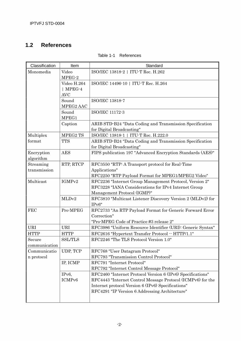
1.2 References
Table 1-1 References
Classification Item Standard Monomedia Video
MPEG-2 ISO/IEC 13818-2 | ITU-T Rec. H.262
Video H.264 | MPEG-4 AVC
ISO/IEC 14496-10 | ITU-T Rec. H.264
Sound MPEG2 AAC
ISO/IEC 13818-7
Sound MPEG1
ISO/IEC 11172-3
Caption ARIB STD-B24 "Data Coding and Transmission Specification for Digital Broadcasting"
Multiplex format
MPEG2 TS ISO/IEC 13818-1 | ITU-T Rec. H.222.0 TTS ARIB STD-B24 "Data Coding and Transmission Specification
for Digital Broadcasting" Encryption algorithm
AES FIPS publication 197 "Advanced Encryption Standards (AES)"
Streaming transmission
RTP, RTCP RFC3550 "RTP: A Transport protocol for Real-Time Applications" RFC2250 "RTP Payload Format for MPEG1/MPEG2 Video"
Multicast IGMPv2 RFC2236 "Internet Group Management Protocol, Version 2" RFC3228 "IANA Considerations for IPv4 Internet Group Management Protocol (IGMP)"
MLDv2 RFC3810 "Multicast Listener Discovery Version 2 (MLDv2) for IPv6"
FEC Pro-MPEG RFC2733 "An RTP Payload Format for Generic Forward Error Correction" "Pro-MPEG Code of Practice #3 release 2"
URI URI RFC3986 "Uniform Resource Identifier (URI): Generic Syntax" HTTP HTTP RFC2616 "Hypertext Transfer Protocol -- HTTP/1.1" Secure communication
SSL/TLS RFC2246 "The TLS Protocol Version 1.0"
Communication protocol
UDP, TCP RFC768 "User Datagram Protocol" RFC793 "Transmission Control Protocol"
IP, ICMP RFC791 "Internet Protocol" RFC792 "Internet Control Message Protocol"
IPv6, ICMPv6
RFC2460 "Internet Protocol Version 6 (IPv6) Specifications" RFC4443 "Internet Control Message Protocol (ICMPv6) for the Internet protocol Version 6 (IPv6) Specifications" RFC4291 "IP Version 6 Addressing Architecture"

IPTVFJ STD-0004
—3—
Digital broadcasting related
ARIB STD-B1 "Receivers for CS Digital Broadcasting" ARIB STD-B5 "Data Multiplex Broadcasting for Conventional Television Using Vertical Blanking Interval" ARIB STD-B10 "Service Information for Digital Broadcasting System" ARIB STD-B20 "Transmission and Operation Conditions for BS Digital Broadcasting" ARIB STD-B21 "Receiver for Digital Broadcasting" ARIB STD-B24 "Data Coding and Transmission Specification for Digital Broadcasting" ARIB STD-B25 "Conditional Access System Specifications for Digital Broadcasting" ARIB STD-B31 "Transmission System for Digital Terrestrial Television Broadcasting" ARIB STD-B32 "Video Coding, Audio Coding and Multiplexing Specifications for Digital Broadcasting" ARIB STD-B38 "Coding, Transmission and Storage Specifications for Broadcasting System Based on Home Servers" ARIB TR-B14 "Operational Guidelines for Digital Terrestrial Television Broadcasting" ARIB TR-B15 "Operational Guidelines for Digital Sattelite Broadcasting" ARIB TR-B27 "Digital Broadcasting System based on Home Servers"
CAS related Marlin Marlin IPTV End-point Service Specification Version 1.0.2(or later version) Marlin IPTV-ES Implementation Guidelines for IP Multicast Version 1.3(or later version) Marlin IPTV-ES/J Specific Compliance Rules for IP Multicast Version 1.3(or later version) Marlin Trust Management Document for IPTV-ES Version 1.3(or later version)
High-speed digital interface related
DTCP "DLNA Networked Device Interoperability Guidelines" Digital Living Network Alliance "Digital Transmission Content Protection Specifications Volume 1" Digital Transmission Licensing Administrator "DTCP Volume 1 Supplement E Mapping DTCP to IP" Digital Transmission Licensing Administrator

IPTVFJ STD-0004
-4-
1.3 Glossary
Table 1-2 Glossary
Terms Description 8-bit character code A code system that requires a lower overhead for
switching between character sets than 7-bit code, which increases character transmission efficiency.
Across-the-board program This is a program which is arranged on the same schedule over two or more consecutive days.
actual (actual TS, EIT actual)
The term “actual TS” refers to a service provider’s own TS. The term “EIT actual” refers to an EIT that is sent out by a service provider’s own TS.
Adaptation field This field is used when transmitting information, including PCR, and stuffing empty spaces.
AES Advanced Encryption Standard: AES is the next-generation encryption standard of the U.S. government that was approved in 2001 by the National Institute of Standards and Technology (NIST) of the U.S. Department of Commerce.
Area code This is the code indicating a specific area that is to be put in the emergency information descriptor during an emergency warning broadcast (see Appendix D to ARIB STD-B10).
ARIB Association of Radio Industries and Business: An organization which standardizes the technologies that are related to radio utilization in Japan, whose members consist of broadcasters, telecommunication companies and manufacturers.
Basic (schedule basic) This is program information that is based on the information sent out in Commonly operated SIs.
Basic registration To register a viewer with a service provider as a customer and allow the viewer to apply for the use of services provided by service providers.
BAT Bouquet Association Table: BAT contains bouquet names, service channels, etc. It is not used in IP broadcasts for the time being.
BCD Binary Coded Decimal BIT Broadcaster Information Table: In IP broadcasting,
BIT indicates a table containing IP broadcaster configuration information. BIT lists services provided by IP broadcasters and links to their portals.
IPTVFJ STD-0004
—5—
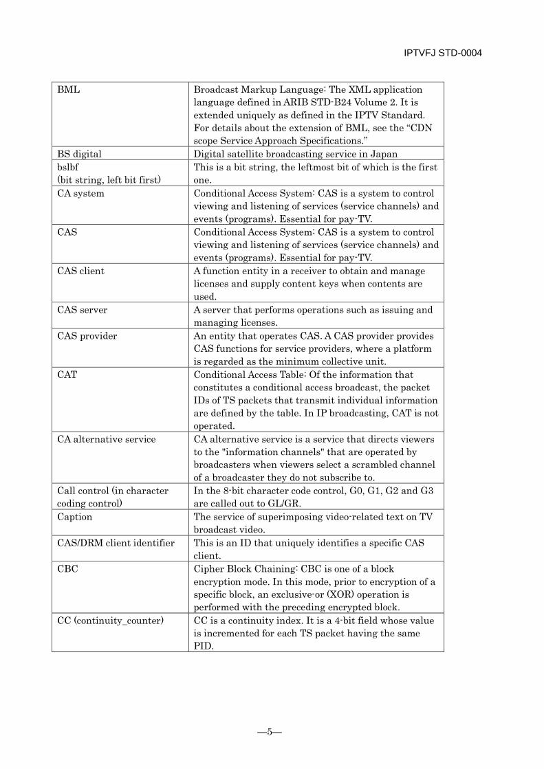
BML Broadcast Markup Language: The XML application language defined in ARIB STD-B24 Volume 2. It is extended uniquely as defined in the IPTV Standard. For details about the extension of BML, see the “CDN scope Service Approach Specifications.”
BS digital Digital satellite broadcasting service in Japan bslbf (bit string, left bit first)
This is a bit string, the leftmost bit of which is the first one.
CA system Conditional Access System: CAS is a system to control viewing and listening of services (service channels) and events (programs). Essential for pay-TV.
CAS Conditional Access System: CAS is a system to control viewing and listening of services (service channels) and events (programs). Essential for pay-TV.
CAS client A function entity in a receiver to obtain and manage licenses and supply content keys when contents are used.
CAS server A server that performs operations such as issuing and managing licenses.
CAS provider An entity that operates CAS. A CAS provider provides CAS functions for service providers, where a platform is regarded as the minimum collective unit.
CAT Conditional Access Table: Of the information that constitutes a conditional access broadcast, the packet IDs of TS packets that transmit individual information are defined by the table. In IP broadcasting, CAT is not operated.
CA alternative service CA alternative service is a service that directs viewers to the "information channels" that are operated by broadcasters when viewers select a scrambled channel of a broadcaster they do not subscribe to.
Call control (in character coding control)
In the 8-bit character code control, G0, G1, G2 and G3 are called out to GL/GR.
Caption The service of superimposing video-related text on TV broadcast video.
CAS/DRM client identifier This is an ID that uniquely identifies a specific CAS client.
CBC Cipher Block Chaining: CBC is one of a block encryption mode. In this mode, prior to encryption of a specific block, an exclusive-or (XOR) operation is performed with the preceding encrypted block.
CC (continuity_counter) CC is a continuity index. It is a 4-bit field whose value is incremented for each TS packet having the same PID.
IPTVFJ STD-0004
-6-
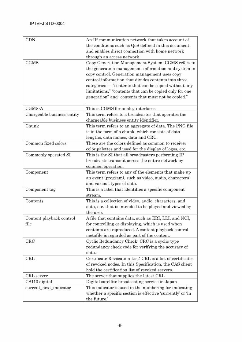
CDN An IP communication network that takes account of the conditions such as QoS defined in this document and enables direct connection with home network through an access network.
CGMS Copy Generation Management System: CGMS refers to the generation management information and system in copy control. Generation management uses copy control information that divides contents into three categories — “contents that can be copied without any limitations,” “contents that can be copied only for one generation” and “contents that must not be copied.”
CGMS-A This is CGMS for analog interfaces. Chargeable business entity This term refers to a broadcaster that operates the
chargeable business entity identifier. Chunk This term refers to an aggregate of data. The PNG file
is in the form of a chunk, which consists of data lengths, data names, data and CRC.
Common fixed colors These are the colors defined as common to receiver color palettes and used for the display of logos, etc.
Commonly operated SI This is the SI that all broadcasters performing IP broadcasts transmit across the entire network by common operation.
Component This term refers to any of the elements that make up an event (program), such as video, audio, characters and various types of data.
Component tag This is a label that identifies a specific component stream.
Contents This is a collection of video, audio, characters, and data, etc. that is intended to be played and viewed by the user.
Content playback control file
A file that contains data, such as ERI, LLI, and NCI, for controlling or displaying, which is used when contents are reproduced. A content playback control metafile is regarded as part of the content.
CRC Cyclic Redundancy Check: CRC is a cyclic-type redundancy check code for verifying the accuracy of data.
CRL Certificate Revocation List: CRL is a list of certificates of revoked nodes. In this Specification, the CAS client hold the certification list of revoked servers.
CRL server The server that supplies the latest CRL. CS110 digital Digital satellite broadcasting service in Japan current_next_indicator This indicator is used in the numbering for indicating
whether a specific section is effective ‘currently’ or ‘in the future.’
IPTVFJ STD-0004
—7—
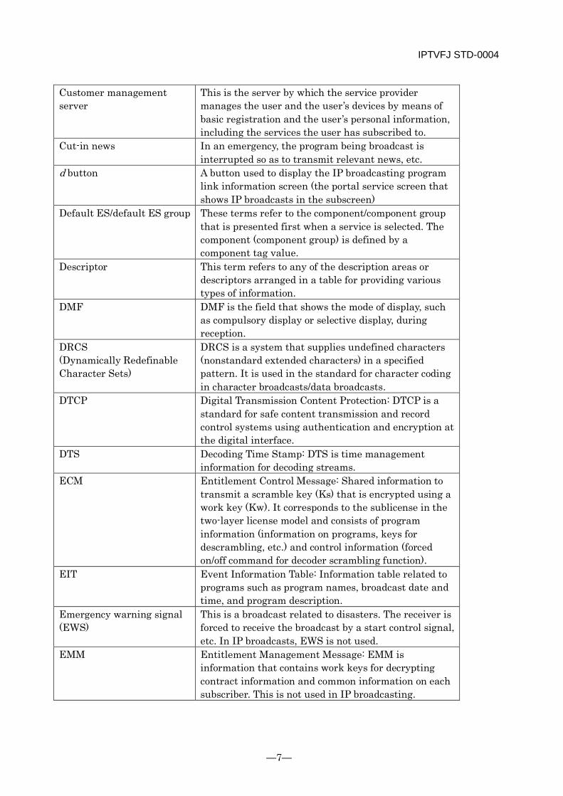
Customer management server
This is the server by which the service provider manages the user and the user’s devices by means of basic registration and the user’s personal information, including the services the user has subscribed to.
Cut-in news In an emergency, the program being broadcast is interrupted so as to transmit relevant news, etc.
d button A button used to display the IP broadcasting program link information screen (the portal service screen that shows IP broadcasts in the subscreen)
Default ES/default ES group These terms refer to the component/component group that is presented first when a service is selected. The component (component group) is defined by a component tag value.
Descriptor This term refers to any of the description areas or descriptors arranged in a table for providing various types of information.
DMF DMF is the field that shows the mode of display, such as compulsory display or selective display, during reception.
DRCS (Dynamically Redefinable Character Sets)
DRCS is a system that supplies undefined characters (nonstandard extended characters) in a specified pattern. It is used in the standard for character coding in character broadcasts/data broadcasts.
DTCP Digital Transmission Content Protection: DTCP is a standard for safe content transmission and record control systems using authentication and encryption at the digital interface.
DTS Decoding Time Stamp: DTS is time management information for decoding streams.
ECM Entitlement Control Message: Shared information to transmit a scramble key (Ks) that is encrypted using a work key (Kw). It corresponds to the sublicense in the two-layer license model and consists of program information (information on programs, keys for descrambling, etc.) and control information (forced on/off command for decoder scrambling function).
EIT Event Information Table: Information table related to programs such as program names, broadcast date and time, and program description.
Emergency warning signal (EWS)
This is a broadcast related to disasters. The receiver is forced to receive the broadcast by a start control signal, etc. In IP broadcasts, EWS is not used.
EMM Entitlement Management Message: EMM is information that contains work keys for decrypting contract information and common information on each subscriber. This is not used in IP broadcasting.
IPTVFJ STD-0004
-8-
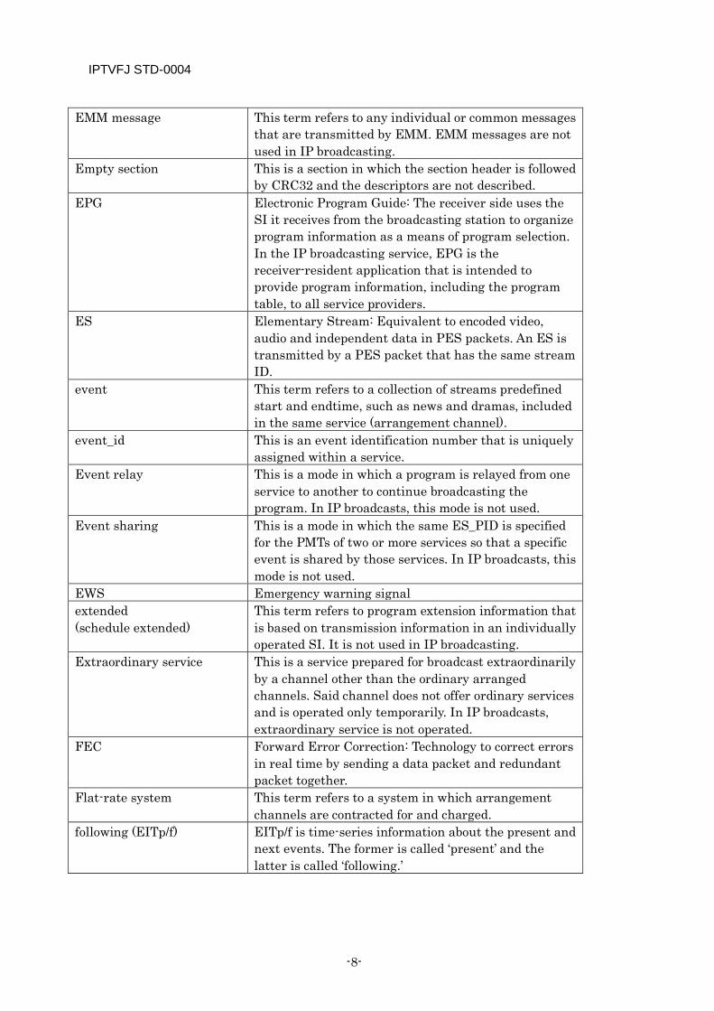
EMM message This term refers to any individual or common messages that are transmitted by EMM. EMM messages are not used in IP broadcasting.
Empty section This is a section in which the section header is followed by CRC32 and the descriptors are not described.
EPG Electronic Program Guide: The receiver side uses the SI it receives from the broadcasting station to organize program information as a means of program selection. In the IP broadcasting service, EPG is the receiver-resident application that is intended to provide program information, including the program table, to all service providers.
ES Elementary Stream: Equivalent to encoded video, audio and independent data in PES packets. An ES is transmitted by a PES packet that has the same stream ID.
event This term refers to a collection of streams predefined start and endtime, such as news and dramas, included in the same service (arrangement channel).
event_id This is an event identification number that is uniquely assigned within a service.
Event relay This is a mode in which a program is relayed from one service to another to continue broadcasting the program. In IP broadcasts, this mode is not used.
Event sharing This is a mode in which the same ES_PID is specified for the PMTs of two or more services so that a specific event is shared by those services. In IP broadcasts, this mode is not used.
EWS Emergency warning signal extended (schedule extended)
This term refers to program extension information that is based on transmission information in an individually operated SI. It is not used in IP broadcasting.
Extraordinary service This is a service prepared for broadcast extraordinarily by a channel other than the ordinary arranged channels. Said channel does not offer ordinary services and is operated only temporarily. In IP broadcasts, extraordinary service is not operated.
FEC Forward Error Correction: Technology to correct errors in real time by sending a data packet and redundant packet together.
Flat-rate system This term refers to a system in which arrangement channels are contracted for and charged.
following (EITp/f) EITp/f is time-series information about the present and next events. The former is called ‘present’ and the latter is called ‘following.’
IPTVFJ STD-0004
—9—
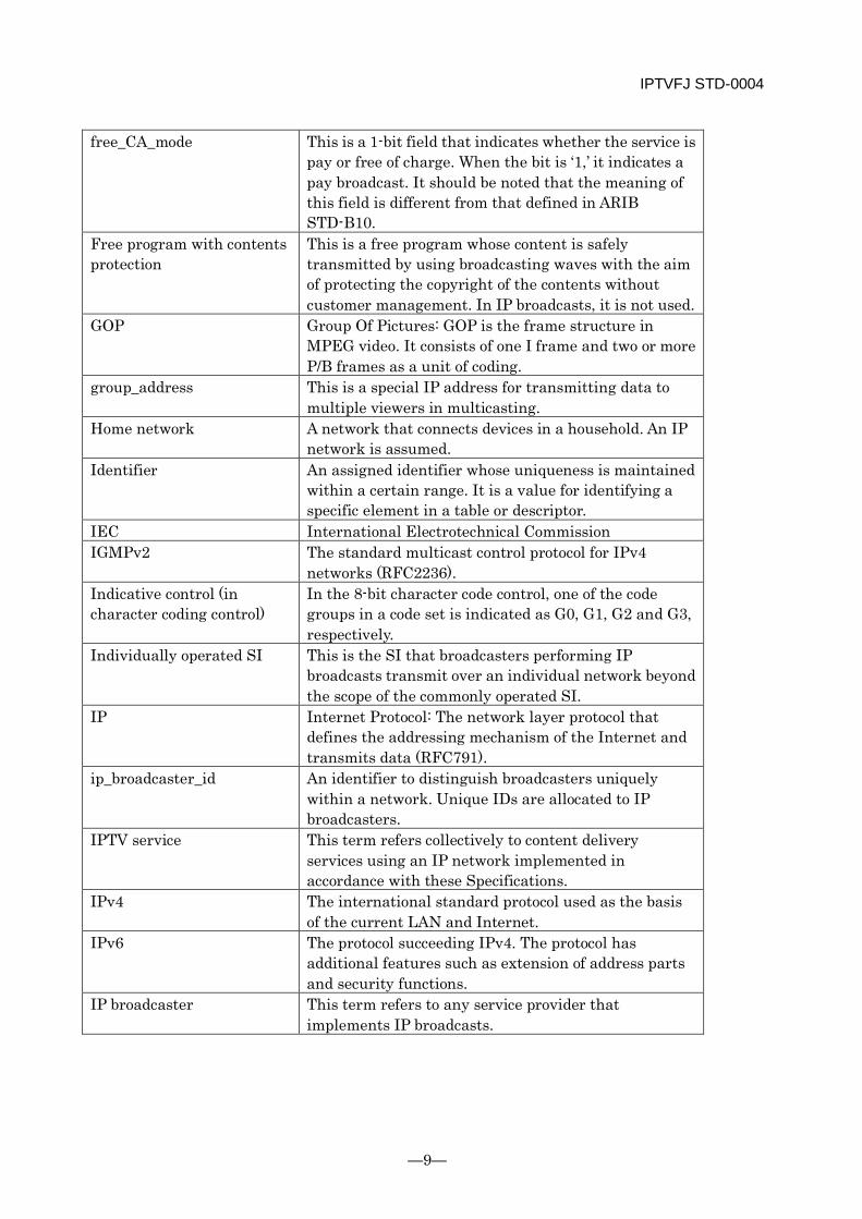
free_CA_mode This is a 1-bit field that indicates whether the service is pay or free of charge. When the bit is ‘1,’ it indicates a pay broadcast. It should be noted that the meaning of this field is different from that defined in ARIB STD-B10.
Free program with contents protection
This is a free program whose content is safely transmitted by using broadcasting waves with the aim of protecting the copyright of the contents without customer management. In IP broadcasts, it is not used.
GOP Group Of Pictures: GOP is the frame structure in MPEG video. It consists of one I frame and two or more P/B frames as a unit of coding.
group_address This is a special IP address for transmitting data to multiple viewers in multicasting.
Home network A network that connects devices in a household. An IP network is assumed.
Identifier An assigned identifier whose uniqueness is maintained within a certain range. It is a value for identifying a specific element in a table or descriptor.
IEC International Electrotechnical Commission IGMPv2 The standard multicast control protocol for IPv4
networks (RFC2236). Indicative control (in character coding control)
In the 8-bit character code control, one of the code groups in a code set is indicated as G0, G1, G2 and G3, respectively.
Individually operated SI This is the SI that broadcasters performing IP broadcasts transmit over an individual network beyond the scope of the commonly operated SI.
IP Internet Protocol: The network layer protocol that defines the addressing mechanism of the Internet and transmits data (RFC791).
ip_broadcaster_id An identifier to distinguish broadcasters uniquely within a network. Unique IDs are allocated to IP broadcasters.
IPTV service This term refers collectively to content delivery services using an IP network implemented in accordance with these Specifications.
IPv4 The international standard protocol used as the basis of the current LAN and Internet.
IPv6 The protocol succeeding IPv4. The protocol has additional features such as extension of address parts and security functions.
IP broadcaster This term refers to any service provider that implements IP broadcasts.
IPTVFJ STD-0004
-10-
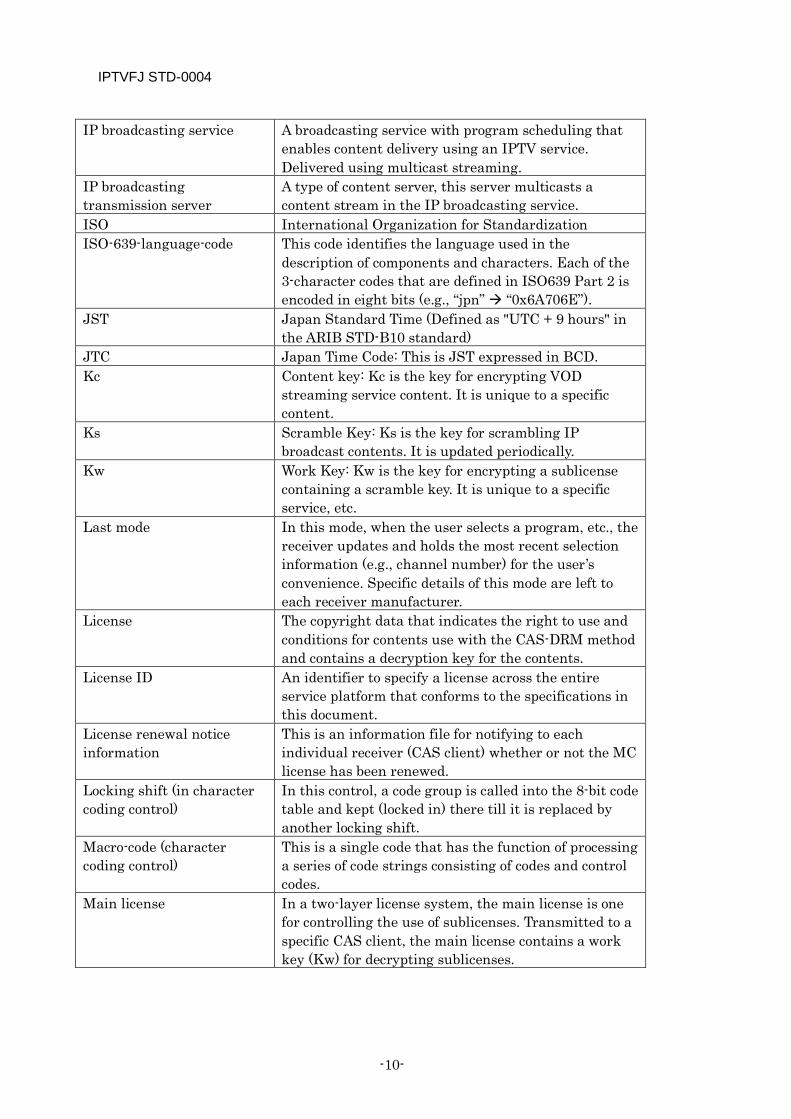
IP broadcasting service A broadcasting service with program scheduling that enables content delivery using an IPTV service. Delivered using multicast streaming.
IP broadcasting transmission server
A type of content server, this server multicasts a content stream in the IP broadcasting service.
ISO International Organization for Standardization ISO-639-language-code This code identifies the language used in the
description of components and characters. Each of the 3-character codes that are defined in ISO639 Part 2 is encoded in eight bits (e.g., “jpn” “0x6A706E”).
JST Japan Standard Time (Defined as "UTC + 9 hours" in the ARIB STD-B10 standard)
JTC Japan Time Code: This is JST expressed in BCD. Kc Content key: Kc is the key for encrypting VOD
streaming service content. It is unique to a specific content.
Ks Scramble Key: Ks is the key for scrambling IP broadcast contents. It is updated periodically.
Kw Work Key: Kw is the key for encrypting a sublicense containing a scramble key. It is unique to a specific service, etc.
Last mode In this mode, when the user selects a program, etc., the receiver updates and holds the most recent selection information (e.g., channel number) for the user’s convenience. Specific details of this mode are left to each receiver manufacturer.
License The copyright data that indicates the right to use and conditions for contents use with the CAS-DRM method and contains a decryption key for the contents.
License ID An identifier to specify a license across the entire service platform that conforms to the specifications in this document.
License renewal notice information
This is an information file for notifying to each individual receiver (CAS client) whether or not the MC license has been renewed.
Locking shift (in character coding control)
In this control, a code group is called into the 8-bit code table and kept (locked in) there till it is replaced by another locking shift.
Macro-code (character coding control)
This is a single code that has the function of processing a series of code strings consisting of codes and control codes.
Main license In a two-layer license system, the main license is one for controlling the use of sublicenses. Transmitted to a specific CAS client, the main license contains a work key (Kw) for decrypting sublicenses.
IPTVFJ STD-0004
—11—
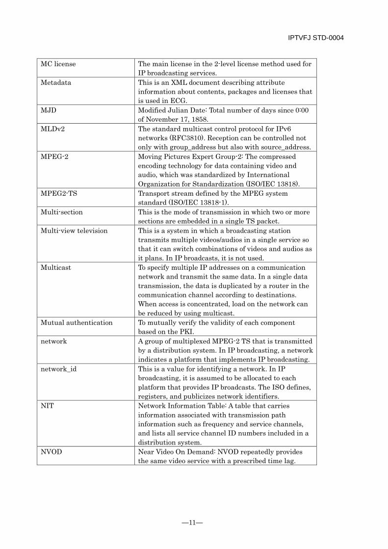
MC license The main license in the 2-level license method used for IP broadcasting services.
Metadata This is an XML document describing attribute information about contents, packages and licenses that is used in ECG.
MJD Modified Julian Date: Total number of days since 0:00 of November 17, 1858.
MLDv2 The standard multicast control protocol for IPv6 networks (RFC3810). Reception can be controlled not only with group_address but also with source_address.
MPEG-2 Moving Pictures Expert Group-2: The compressed encoding technology for data containing video and audio, which was standardized by International Organization for Standardization (ISO/IEC 13818).
MPEG2-TS Transport stream defined by the MPEG system standard (ISO/IEC 13818-1).
Multi-section This is the mode of transmission in which two or more sections are embedded in a single TS packet.
Multi-view television This is a system in which a broadcasting station transmits multiple videos/audios in a single service so that it can switch combinations of videos and audios as it plans. In IP broadcasts, it is not used.
Multicast To specify multiple IP addresses on a communication network and transmit the same data. In a single data transmission, the data is duplicated by a router in the communication channel according to destinations. When access is concentrated, load on the network can be reduced by using multicast.
Mutual authentication To mutually verify the validity of each component based on the PKI.
network A group of multiplexed MPEG-2 TS that is transmitted by a distribution system. In IP broadcasting, a network indicates a platform that implements IP broadcasting.
network_id This is a value for identifying a network. In IP broadcasting, it is assumed to be allocated to each platform that provides IP broadcasts. The ISO defines, registers, and publicizes network identifiers.
NIT Network Information Table: A table that carries information associated with transmission path information such as frequency and service channels, and lists all service channel ID numbers included in a distribution system.
NVOD Near Video On Demand: NVOD repeatedly provides the same video service with a prescribed time lag.
IPTVFJ STD-0004
-12-
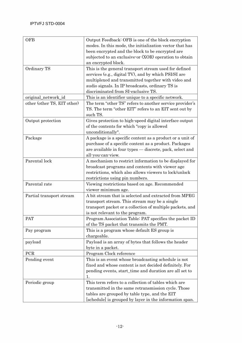
OFB Output Feedback: OFB is one of the block encryption modes. In this mode, the initialization vector that has been encrypted and the block to be encrypted are subjected to an exclusive-or (XOR) operation to obtain an encrypted block.
Ordinary TS This is the general transport stream used for defined services (e.g., digital TV), and by which PSI/SI are multiplexed and transmitted together with video and audio signals. In IP broadcasts, ordinary TS is discriminated from SI-exclusive TS.
original_network_id This is an identifier unique to a specific network. other (other TS, EIT other) The term “other TS” refers to another service provider’s
TS. The term “other EIT” refers to an EIT sent out by such TS.
Output protection Gives protection to high-speed digital interface output of the contents for which "copy is allowed unconditionally".
Package A package is a specific content as a product or a unit of purchase of a specific content as a product. Packages are available in four types — discrete, pack, select and all-you-can-view.
Parental lock A mechanism to restrict information to be displayed for broadcast programs and contents with viewer age restrictions, which also allows viewers to lock/unlock restrictions using pin numbers.
Parental rate Viewing restrictions based on age. Recommended viewer minimum age.
Partial transport stream A bit stream that is selected and extracted from MPEG transport stream. This stream may be a single transport packet or a collection of multiple packets, and is not relevant to the program.
PAT Program Association Table: PAT specifies the packet ID of the TS packet that transmits the PMT.
Pay program This is a program whose default ES group is chargeable.
payload Payload is an array of bytes that follows the header byte in a packet.
PCR Program Clock reference Pending event This is an event whose broadcasting schedule is not
fixed and whose content is not decided definitely. For pending events, start_time and duration are all set to 1.
Periodic group This term refers to a collection of tables which are transmitted in the same retransmission cycle. Those tables are grouped by table type, and the EIT [schedule] is grouped by layer in the information span.
IPTVFJ STD-0004
—13—
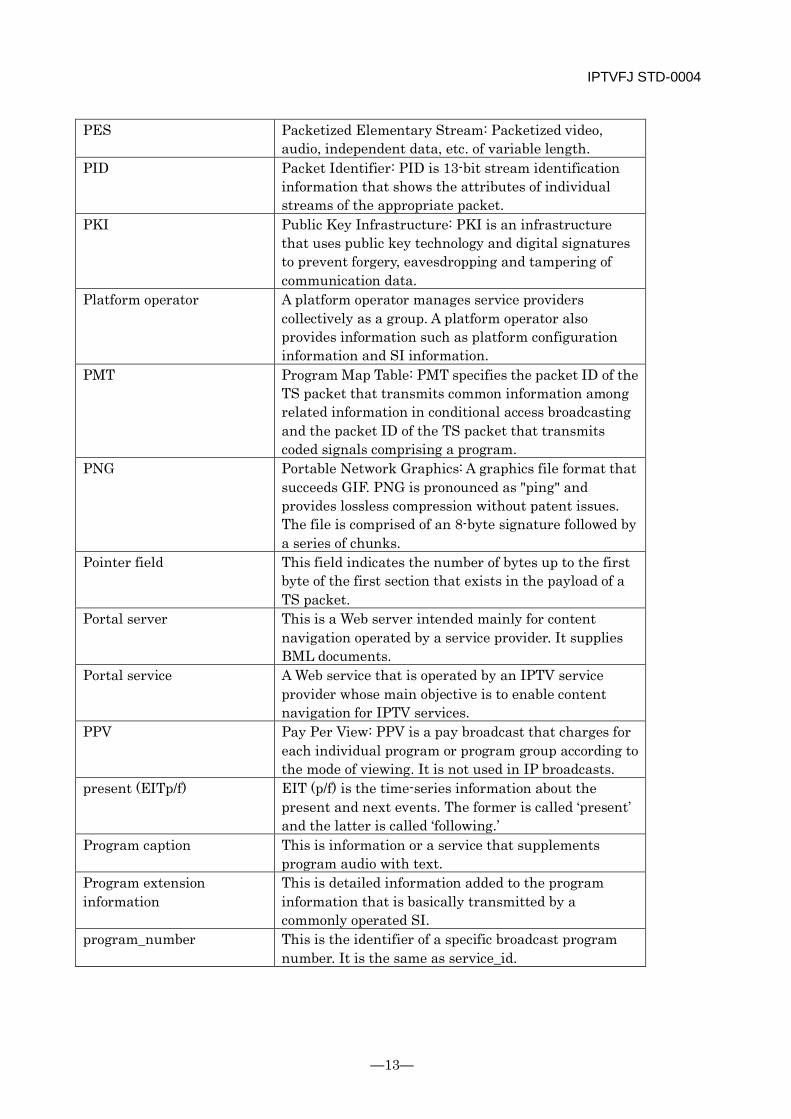
PES Packetized Elementary Stream: Packetized video, audio, independent data, etc. of variable length.
PID Packet Identifier: PID is 13-bit stream identification information that shows the attributes of individual streams of the appropriate packet.
PKI Public Key Infrastructure: PKI is an infrastructure that uses public key technology and digital signatures to prevent forgery, eavesdropping and tampering of communication data.
Platform operator A platform operator manages service providers collectively as a group. A platform operator also provides information such as platform configuration information and SI information.
PMT Program Map Table: PMT specifies the packet ID of the TS packet that transmits common information among related information in conditional access broadcasting and the packet ID of the TS packet that transmits coded signals comprising a program.
PNG Portable Network Graphics: A graphics file format that succeeds GIF. PNG is pronounced as "ping" and provides lossless compression without patent issues. The file is comprised of an 8-byte signature followed by a series of chunks.
Pointer field This field indicates the number of bytes up to the first byte of the first section that exists in the payload of a TS packet.
Portal server This is a Web server intended mainly for content navigation operated by a service provider. It supplies BML documents.
Portal service A Web service that is operated by an IPTV service provider whose main objective is to enable content navigation for IPTV services.
PPV Pay Per View: PPV is a pay broadcast that charges for each individual program or program group according to the mode of viewing. It is not used in IP broadcasts.
present (EITp/f) EIT (p/f) is the time-series information about the present and next events. The former is called ‘present’ and the latter is called ‘following.’
Program caption This is information or a service that supplements program audio with text.
Program extension information
This is detailed information added to the program information that is basically transmitted by a commonly operated SI.
program_number This is the identifier of a specific broadcast program number. It is the same as service_id.
IPTVFJ STD-0004
-14-
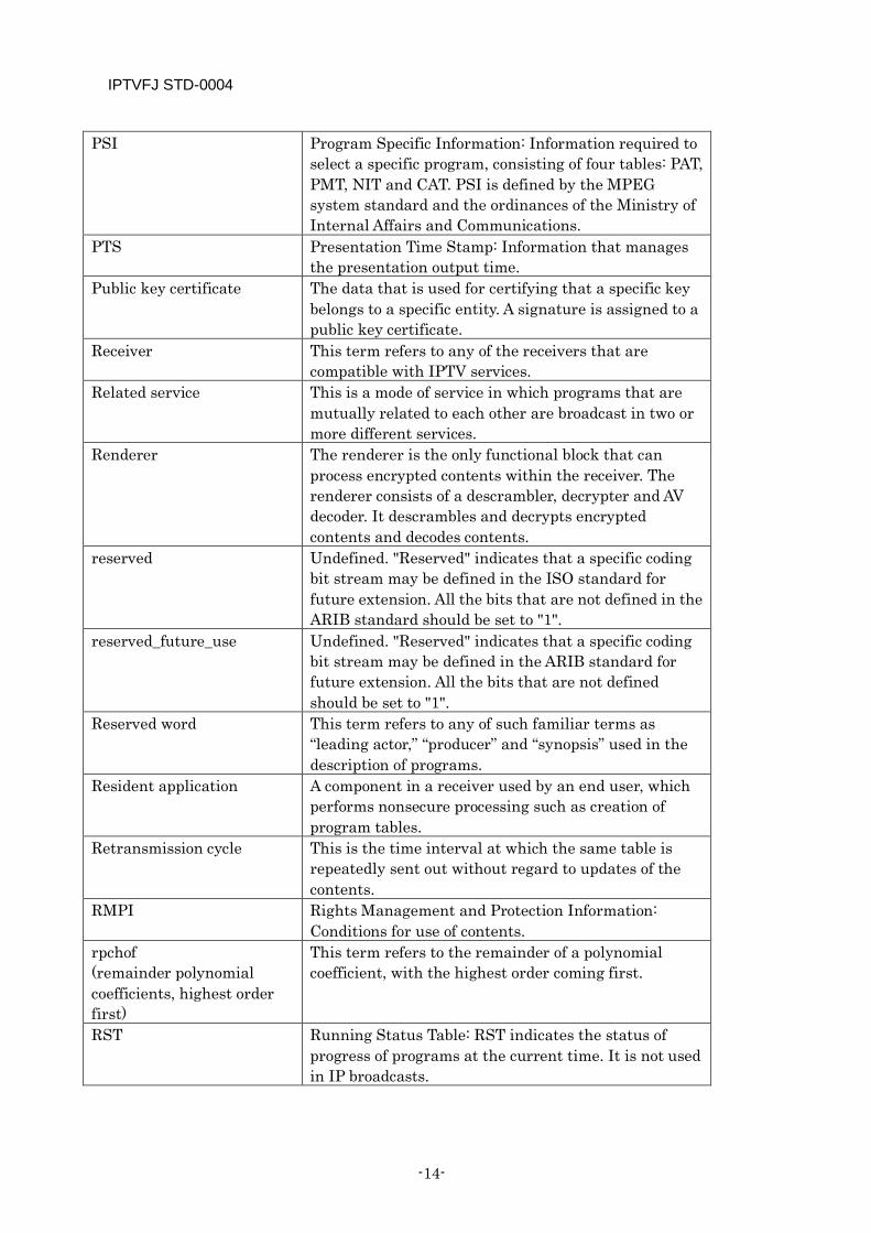
PSI Program Specific Information: Information required to select a specific program, consisting of four tables: PAT, PMT, NIT and CAT. PSI is defined by the MPEG system standard and the ordinances of the Ministry of Internal Affairs and Communications.
PTS Presentation Time Stamp: Information that manages the presentation output time.
Public key certificate The data that is used for certifying that a specific key belongs to a specific entity. A signature is assigned to a public key certificate.
Receiver This term refers to any of the receivers that are compatible with IPTV services.
Related service This is a mode of service in which programs that are mutually related to each other are broadcast in two or more different services.
Renderer The renderer is the only functional block that can process encrypted contents within the receiver. The renderer consists of a descrambler, decrypter and AV decoder. It descrambles and decrypts encrypted contents and decodes contents.
reserved Undefined. "Reserved" indicates that a specific coding bit stream may be defined in the ISO standard for future extension. All the bits that are not defined in the ARIB standard should be set to "1".
reserved_future_use Undefined. "Reserved" indicates that a specific coding bit stream may be defined in the ARIB standard for future extension. All the bits that are not defined should be set to "1".
Reserved word This term refers to any of such familiar terms as “leading actor,” “producer” and “synopsis” used in the description of programs.
Resident application A component in a receiver used by an end user, which performs nonsecure processing such as creation of program tables.
Retransmission cycle This is the time interval at which the same table is repeatedly sent out without regard to updates of the contents.
RMPI Rights Management and Protection Information: Conditions for use of contents.
rpchof (remainder polynomial coefficients, highest order first)
This term refers to the remainder of a polynomial coefficient, with the highest order coming first.
RST Running Status Table: RST indicates the status of progress of programs at the current time. It is not used in IP broadcasts.
IPTVFJ STD-0004
—15—
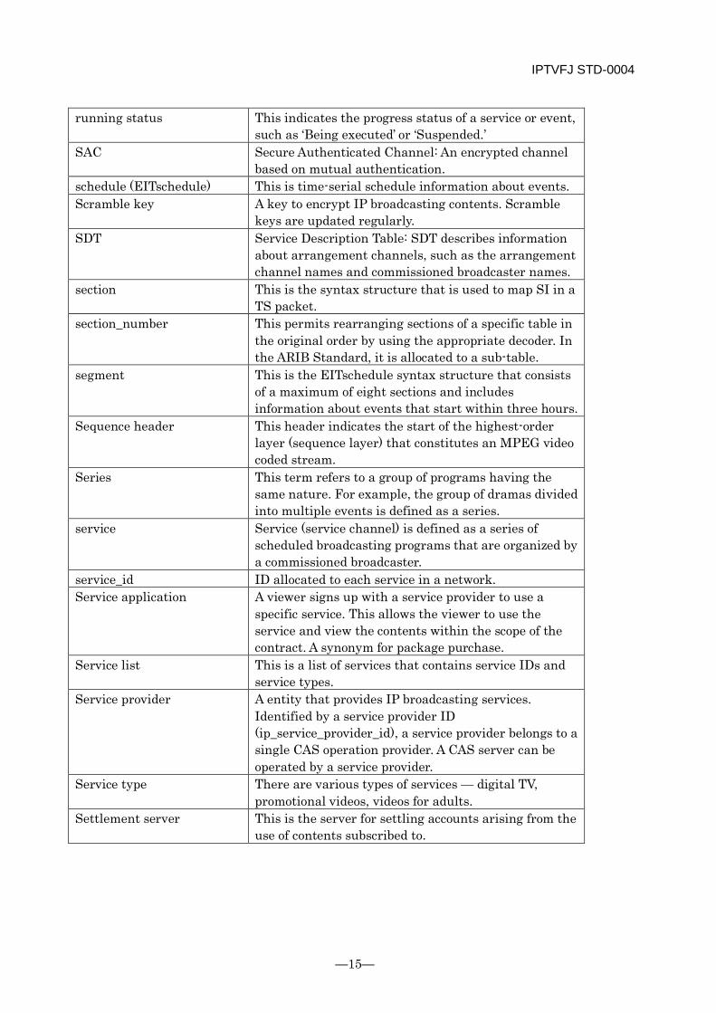
running status This indicates the progress status of a service or event, such as ‘Being executed’ or ‘Suspended.’
SAC Secure Authenticated Channel: An encrypted channel based on mutual authentication.
schedule (EITschedule) This is time-serial schedule information about events. Scramble key A key to encrypt IP broadcasting contents. Scramble
keys are updated regularly. SDT Service Description Table: SDT describes information
about arrangement channels, such as the arrangement channel names and commissioned broadcaster names.
section This is the syntax structure that is used to map SI in a TS packet.
section_number This permits rearranging sections of a specific table in the original order by using the appropriate decoder. In the ARIB Standard, it is allocated to a sub-table.
segment This is the EITschedule syntax structure that consists of a maximum of eight sections and includes information about events that start within three hours.
Sequence header This header indicates the start of the highest-order layer (sequence layer) that constitutes an MPEG video coded stream.
Series This term refers to a group of programs having the same nature. For example, the group of dramas divided into multiple events is defined as a series.
service Service (service channel) is defined as a series of scheduled broadcasting programs that are organized by a commissioned broadcaster.
service_id ID allocated to each service in a network. Service application A viewer signs up with a service provider to use a
specific service. This allows the viewer to use the service and view the contents within the scope of the contract. A synonym for package purchase.
Service list This is a list of services that contains service IDs and service types.
Service provider A entity that provides IP broadcasting services. Identified by a service provider ID (ip_service_provider_id), a service provider belongs to a single CAS operation provider. A CAS server can be operated by a service provider.
Service type There are various types of services — digital TV, promotional videos, videos for adults.
Settlement server This is the server for settling accounts arising from the use of contents subscribed to.

IPTVFJ STD-0004
-16-
SI Service Information: Various information defined to improve the convenience of program selection. SI is defined by the ordinances of the Ministry of Internal Affairs and Communications and its details are defined by the ARIB standard. SI also includes MPEG-2 PSI information in addition to the expanded portion of the ARIB standard.
SI-exclusive TS A special transport stream that does not contain video and audio signals but contains SI only. Service is not defined, so PAT and PMT are not multiplexed. In IP broadcasting, SI dedicated streams are used to transmit the EIT schedule for all channels collectively and effectively.
SI transmission parameter This parameter indicates the period of retransmission for each periodic group. It is described in the SI transmission parameter descriptor.
Single program This is a program which is not arranged in a series or across the board. It is an irregular program.
Single shift (in control of character coding)
This term refers to the control mode in which only one code that follows a single shift is temporarily called into the 8-bit coding table.
source_address This is the IP address of the server that transmits data to group_address in a multicast.
Special symbol This is a so-called undefined character. Special symbols, such as synthesized characters, are arranged separately from Chinese characters, alphanumeric characters, etc.
ST Stuffing Table: ST is used to invalidate a specific table. STC System Time Clock: STC is a 27-MHz reference timing
clock in an encoder/decoder. STD Standard Stuffing This term refers to the process of filling the remainder
of a TS packet with 0xFF. sub_table This is a group of sections that have the same table_id
and the same table_id_extension. Sublicense In a two-layer license system, this term refers to a
license that is sent out without specifying any CAS client. The scramble key (Ks) that is periodically updated by the work key (Kw) of the main license is encrypted and sent out. When used in IP broadcasting, the sublicense is transmitted in the ECM mode.
Superimpose A service that provides captions that are asynchronous to the main video, audio and data. It is used for up-to-the-minute news, changes in the program schedule, and time signals, etc.
IPTVFJ STD-0004
—17—
table This consists of two or more sub-tables that have the same table_id.
table_id This identifier defines the table to which a section belongs.
table_id_extension This is used to identify a specific sub-table. Temporary storage This term refers to the process of temporarily storing
content on a recording medium to permit viewing the content on a time-shift basis.
Tier This term refers to a system in which each program or each group of programs is contracted for and charged.
Tier bit array The array of tier bits corresponding to the contracts (tiers) that are included in the MC license. The tier bit array indicates whether there are multiple contracts for the MC license.
TOT Time Offset Table: TOT specifies the current date and time, and the time difference between the actual time and the displayed time when the summer time is applied. In IP broadcasting, TOT and TDT are not transmitted.
Transmission frequency This is a synonym for retransmission cycle. TS Transport Stream: The transport stream defined by the
MPEG system standard (ISO/IEC 13818-1). In IP broadcasts, one network contains multiple TSes that are classified as normal TS and SI-exclusive TS.
TS_id This is an identifier allocated to each TS. It is unique to each TS within a network.
TS packet This is a fixed-length (188-byte) packet defined in ISO/IEC 13818-1.
TTS Time-stamped TS: TTS is a transport stream in which each of 188-byte MPEG-2 transport packets is prefixed with a 4-byte timestamp (in increments of 27 MHz). It is defined in ARIB STD-B24.
Two-layer license system This is a license system whereby the sublicenses controlling the use of contents and the main license controlling the use of sublicenses are transmitted from the CAS server to the CAS client.
uimsbf This is an unsigned integer with the most significant bit coming first.
URI Uniform Resource Identifier: The description method to indicate where information is located. URI includes URL.
UTC Universal Time Coordinated: Time commonly used around the world that is determined based on international agreement.

IPTVFJ STD-0004
-18-
version_number When updating information in a table, a sub-table having the next version number is sent out to indicate that new PSI/SI data, including the latest information, is going to be transmitted.
Work key (Kw) This is the key for encrypting a sublicense containing a scramble key (Ks). It is unique to each service, etc.
IPTVFJ STD-0004
—19—
Chapter 2 Overview
2.1 Service Requirements The service requirements on which the contents of these Specifications are based are described below.
(1) Network Environment
As the applicable network, a Contents Delivery Network (CDN) that supports multicast transmissions and that takes into account QoS and other conditions relating to the delivery of video contents is to be used.
(2) Receiver Functions and Presupposed Product Types
Receivers exclusively for reception and playback Receivers that are not provided with a large-capacity storage medium (HDD, etc.) and that only function to receive and reproduce IPTV services. As product types, TV and set-top boxes are assumed.
Receivers with built-in storage Receivers that incorporate a large-capacity storage medium (HDD, etc.). In addition receiving and reproducing IPTV services, the receiver records IP broadcasting services. As product type, HDD recorders are assumed.
(3) Mode of Operation for IP Broadcasting Service
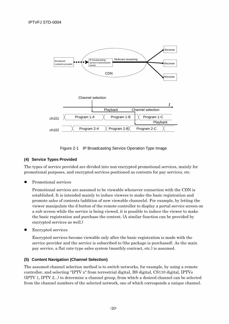
As the mode of operation for IP broadcasting service, it is assumed that, as shown in Figure 2-1, service streams sent out over a dedicated line, etc. by a contents provider outside the CDN are transmitted as an IP broadcasting service by multicast streaming to receivers via an IP broadcasting service transmission server operated by a service provider.
It is also assumed that IP broadcasting service providers produce service streams for themselves and multicast them directly to the CDN from its server.
IPTVFJ STD-0004
-20-
Figure 2-1 IP Broadcasting Service Operation Type Image
(4) Service Types Provided
The types of service provided are divided into non-encrypted promotional services, mainly for promotional purposes, and encrypted services positioned as contents for pay services, etc.
Promotional services
Promotional services are assumed to be viewable whenever connection with the CDN is established. It is intended mainly to induce viewers to make the basic registration and promote sales of contents (addition of new viewable channels). For example, by letting the viewer manipulate the d button of the remote controller to display a portal service screen on a sub-screen while the service is being viewed, it is possible to induce the viewer to make the basic registration and purchase the content. (A similar function can be provided by encrypted services as well.)
Encrypted services
Encrypted services become viewable only after the basic registration is made with the service provider and the service is subscribed to (the package is purchased). As the main pay service, a flat rate-type sales system (monthly contract, etc.) is assumed.
(5) Content Navigation (Channel Selection)
The assumed channel selection method is to switch networks, for example, by using a remote controller, and selecting "IPTV x" from terrestrial digital, BS digital, CS110 digital, IPTVs (IPTV 1, IPTV 2...) to determine a channel group, from which a desired channel can be selected from the channel numbers of the selected network, one of which corresponds a unique channel.
IP broadcasting service transmission server
Receiver
Broadcast contents provider
CDN
Multicast streaming
Program 1-A
t
ch101
ch102
Channel selection
Playback Channel selection
Receiver
Receiver
Program 1-B Program 1-C
Program 2-A Program 2-B Program 2-C
Playback
IPTVFJ STD-0004
—21—
The number of affiliated channels corresponds to the number of the platform operators operating IP broadcasting services on the CDN, with whom the viewers conclude contracts. This number may increase or decrease in the future.
Several means of channel selection are presupposed as follows.
Direct selection and up/down channel selection When "IPTV x" is selected using the network switching button of a remote controller, the viewer selects a desired channel directly by entering the channel number using the number buttons, or selects a desired channel by pressing the up/down button until the desired channel is chosen by going through the channels sequentially. Application of one-touch channel selection can also be assumed.
Channel selection by EPG When "IPTV x" is selected by using the network switching button of a remote controller, the viewer uses the EPG button to display the EPG screen. In the EPG screen, the viewer selects a desired channel by choosing a channel (program). Alternatively, the viewer can work scheduled channel selection by selecting desired program and performing requried operation.
Channel selection using a portal The viewer selects a desired channel by accessing the portal of a specific provider to display the portal screen and selecting a channel (program) in the channel selection/program selection screen of the IP broadcasting service, which is generated by the provider in multimedia format.
2.2 System Model An IP broadcasting service system model is shown in Figure 2-2. It should be noted that the classification of servers in the figure is a logical one: it does not represent the physical server configuration. It should also be noted that not all of the server functions in the system model need be provided.
The outline of each of the servers is given below.
2.2.1 SI Server The SI server supplies the PSI/SI information that is necessary for the receiver to select an IP broadcasting service and display the EPG.
In the CDN scope, the SI server is operated by the platform provider that offers IP broadcasting service, and this server is necessary for the service provider to provide its IP broadcasting service. The receiver obtains the PSI/SI information by periodically accessing stream of the multicast address that can be got from “PF configuration information” defined in 5.1.2 “PF configuration information file” of IPTVFJ STD-0006 “IPTV Standard: CDN-scope Service Approach Specifications.”
IPTVFJ STD-0004
-22-
2.2.2 CAS Server The CAS server issues and manages licenses and establishes a high-security communication link with the CAS client of the receiver to supply licenses. The receiver obtains a license by accessing this server at the time of content playback.
In the CDN scope, the CAS server is operated by the CAS operator, and this server is indispensable for the service provider to provide its IP broadcasting service. As the URI of this CAS server, it is used the "CAS server URI"that is recorded in the NVRAM of the receiver by the basic registration information recording function of the BML document of the service provider portal, during “basic registration” as defined in 3.3.1.4.3 “Management of Basic registration information” of IPTVFJ STD-0006 “IPTV Standard: CDN-scope Service Approach Specifications.”
2.2.3 Portal Server The portal server provides portal services for entry into and navigation through the IPTV service. This server provides the means of IPTV service promotion and content navigation as Web services. In addition, the portal server may process various types of registration screen and perform authentication processing in cooperation with the customer/contract management functions,. It is assumed that the receiver accesses this server by the viewer’s operation.
In the CDN scope, a portal server is operated by each service provider and every service provider must have this server. The URI of this server is obtained from “PF configuration information” defined in 5.1.2 “PF configuration information file” of IPTVFJ STD-B0006 “IPTV Standard: CDN-scope Service Approach Specifications.”
2.2.4 License Renewal Notification Information Server This server notifies the receiver whether or not the license for IP broadcasting service has been renewed.
In the CDN scope, this server is, as a rule, operated by the service provider that utilizes this renewal scheme. The receiver periodically accesses the license renewal notification information server of the service provider that viewer has finished the basic registration for obtainning license renewal notification information by using the URI of the server obtained from “PF configuration information” defined in 5.1.2 “PF configuration information file” of IPTVFJ STD-0006 “IPTV Standard: CDN-scope Service Approach Specifications.”
2.2.5 IP Broadcasting Service Transmission Server This is a server operated by the service provider that provides IP broadcasting service. This server delivers video streams for providing IP broadcasting services. It is generally assumed that the server receives broadcast video signals sent out from transmitting equipment of an outside contents provider and transmits them by multicast streaming. When the receiver selects an IP broadcasting service, it must access the stream of the multicast address associated with that service. In the CDN scope, the IP broadcasting service stream transmitted from this server is accessed via the NIT parameters of the SI information that is obtained from the SI server.

IPTVFJ STD-0004
—23—
2.2.6 Customer/Contract Management Server and Billing/Settlement Server This is the server for customer management, including management of contracts with users, and is the server for settlement of accounts are outside of the scope of these Specifications.
These servers manage the identifiers involved in basic registration and the CAS/DRM client identifiers (DRM_ID) and, together with the portal server, perform authentication processing and manage purchases, etc. by users while the receiver is connected to the portal server. These servers do not directly communicate with the receiver. When providing services to the receiver, they are connected to the receiver via a portal server, etc.
Figure 2-2 IP Broadcasting Service System Model
Receiver
Billing/settlement server
IP broadcasting service
transmission equipment
Streams exclusive for SI (multicast)
Licenses
Web pages
License renewal notification information
IP broadcasting service streams (multicast)
SI server
CAS server
Customer/contract management server
License renewal notification server
IP broadcasting service transmission server
Portal server
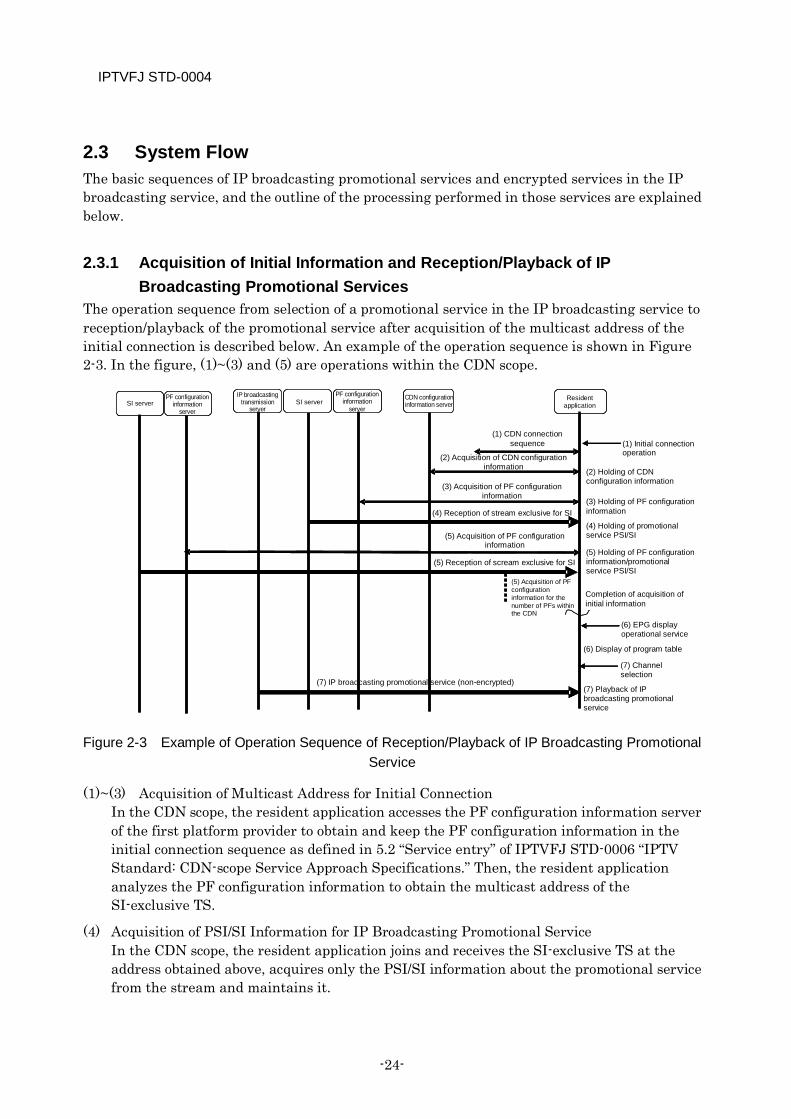
IPTVFJ STD-0004
-24-
2.3 System Flow The basic sequences of IP broadcasting promotional services and encrypted services in the IP broadcasting service, and the outline of the processing performed in those services are explained below.
2.3.1 Acquisition of Initial Information and Reception/Playback of IP Broadcasting Promotional Services
The operation sequence from selection of a promotional service in the IP broadcasting service to reception/playback of the promotional service after acquisition of the multicast address of the initial connection is described below. An example of the operation sequence is shown in Figure 2-3. In the figure, (1)~(3) and (5) are operations within the CDN scope.
Figure 2-3 Example of Operation Sequence of Reception/Playback of IP Broadcasting Promotional Service
(1)~(3) Acquisition of Multicast Address for Initial Connection In the CDN scope, the resident application accesses the PF configuration information server of the first platform provider to obtain and keep the PF configuration information in the initial connection sequence as defined in 5.2 “Service entry” of IPTVFJ STD-0006 “IPTV Standard: CDN-scope Service Approach Specifications.” Then, the resident application analyzes the PF configuration information to obtain the multicast address of the SI-exclusive TS.
(4) Acquisition of PSI/SI Information for IP Broadcasting Promotional Service In the CDN scope, the resident application joins and receives the SI-exclusive TS at the address obtained above, acquires only the PSI/SI information about the promotional service from the stream and maintains it.
(2) Acquisition of CDN configuration information
Resident application
CDN configuration information server
PF configuration information
server
IP broadcasting transmission
server SI server SI server
(1) CDN connection sequence
PF configuration information
server
(1) Initial connection operation
(2) Holding of CDN configuration information
(3) Acquisition of PF configuration information
(3) Holding of PF configuration information (4) Reception of stream exclusive for SI (4) Holding of promotional service PSI/SI (5) Acquisition of PF configuration
information
(5) Reception of scream exclusive for SI (5) Holding of PF configuration information/promotional service PSI/SI
(5) Acquisition of PF configuration information for the number of PFs within the CDN
Completion of acquisition of initial information
(6) EPG display operational service
(6) Display of program table (7) Channel selection
(7) IP broadcasting promotional service (non-encrypted) (7) Playback of IP broadcasting promotional service
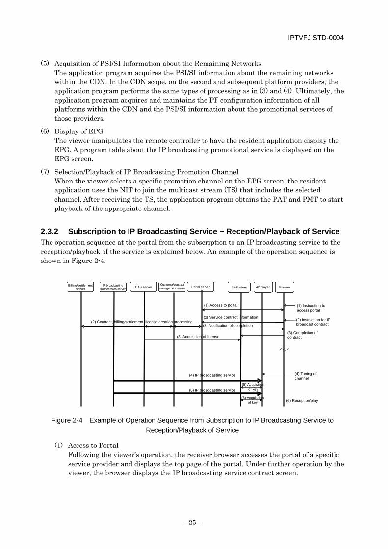
IPTVFJ STD-0004
—25—
(5) Acquisition of PSI/SI Information about the Remaining Networks The application program acquires the PSI/SI information about the remaining networks within the CDN. In the CDN scope, on the second and subsequent platform providers, the application program performs the same types of processing as in (3) and (4). Ultimately, the application program acquires and maintains the PF configuration information of all platforms within the CDN and the PSI/SI information about the promotional services of those providers.
(6) Display of EPG The viewer manipulates the remote controller to have the resident application display the EPG. A program table about the IP broadcasting promotional service is displayed on the EPG screen.
(7) Selection/Playback of IP Broadcasting Promotion Channel When the viewer selects a specific promotion channel on the EPG screen, the resident application uses the NIT to join the multicast stream (TS) that includes the selected channel. After receiving the TS, the application program obtains the PAT and PMT to start playback of the appropriate channel.
2.3.2 Subscription to IP Broadcasting Service ~ Reception/Playback of Service The operation sequence at the portal from the subscription to an IP broadcasting service to the reception/playback of the service is explained below. An example of the operation sequence is shown in Figure 2-4.
Figure 2-4 Example of Operation Sequence from Subscription to IP Broadcasting Service to Reception/Playback of Service
(1) Access to Portal Following the viewer’s operation, the receiver browser accesses the portal of a specific service provider and displays the top page of the portal. Under further operation by the viewer, the browser displays the IP broadcasting service contract screen.
Billing/settlement server
IP broadcasting transmission server CAS server
Customer/contract management server Portal server CAS client AV player
(1) Access to portal (1) Instruction to access portal
(2) Contract, billing/settlement, license creation processing (2) Service contract information (2) Instruction for IP broadcast contract (3) Notification of completion
(3) Completion of contract (3) Acquisition of license
(4) IP broadcasting service (4) Tuning of channel
(5) Acquisition of key (6) IP broadcasting service
(6) Acquisition of key (6) Reception/play
Browser
IPTVFJ STD-0004
-26-
(2) Subscription to Service Following the viewer’s operation, the browser transmits to the portal server the information about the subscription to a specific service, containing the CAS/DRM client identifier (DRM_ID), etc. Then, the portal server communicates with other related servers so that the customer/contract management server registers the subscription, that the billing/settlement server performs the appropriate processing, and that the CAS server generates a license.
(3) Processing after Completion of Subscription Upon completion of the processing of the subscription at the server side, the browser executes the appropriate document to obtain the license from the CAS server and maintains it in the CAS client.
(4) Selection of IP Broadcasting Service Channel After completing the subscription to the IP broadcasting service, the viewer uses the remote controller to select the IP broadcasting channel that provides the subscribed service. The resident application uses the NIT to join the appropriate stream and start receiving the stream.
(5) Acquisition of Scramble Key The AV player obtains the ECM from the received stream and inputs it to the CAS client. When the license has been issued, the CAS client outputs a scramble key.
(6) Reception/Playback of IP Broadcasting Service The AV player uses the above scramble key to decrypt the received stream and starts playing it. After that, each time the ECM is updated, the AV player performs the processing in (5) above and continues decrypting the stream by using the scramble key that is continually updated.
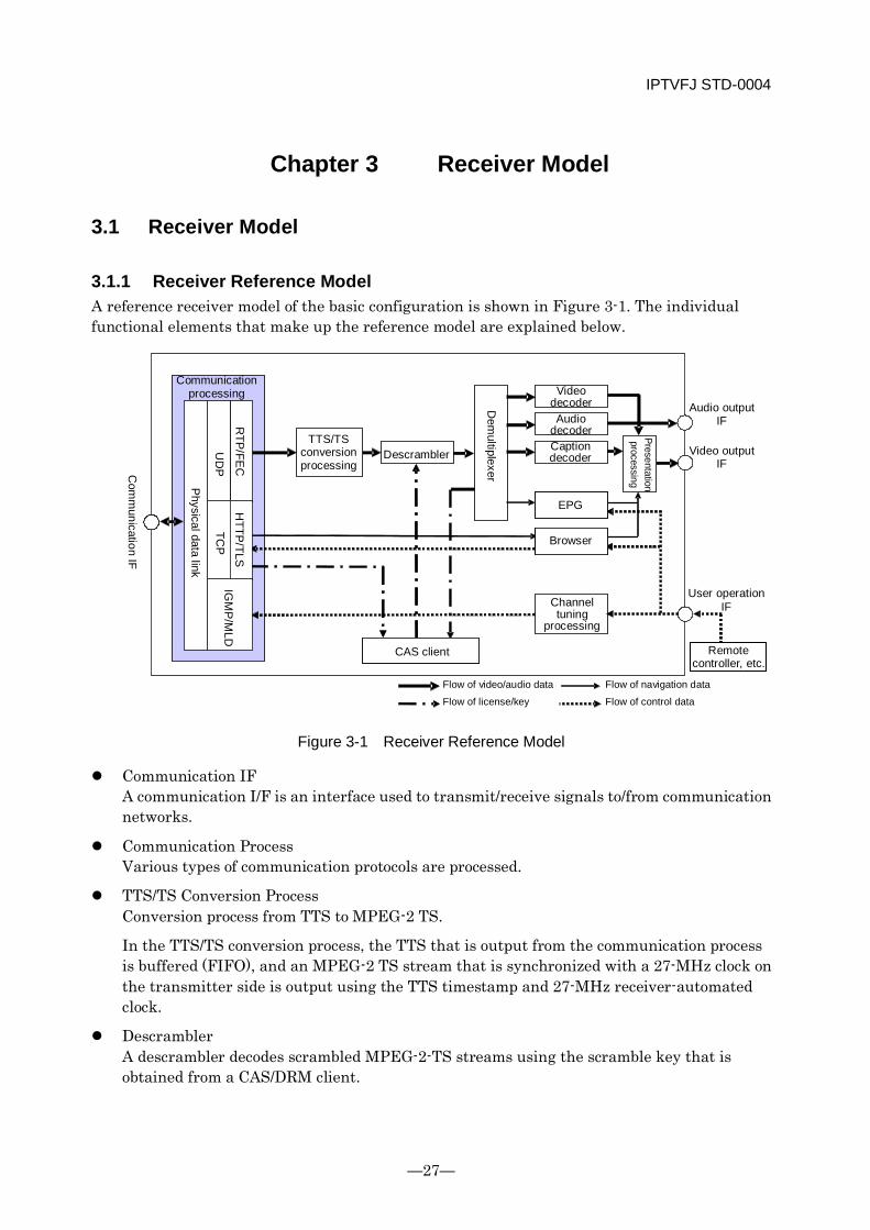
IPTVFJ STD-0004
—27—
Chapter 3 Receiver Model
3.1 Receiver Model
3.1.1 Receiver Reference Model A reference receiver model of the basic configuration is shown in Figure 3-1. The individual functional elements that make up the reference model are explained below.
Figure 3-1 Receiver Reference Model
Communication IF A communication I/F is an interface used to transmit/receive signals to/from communication networks.
Communication Process Various types of communication protocols are processed.
TTS/TS Conversion Process Conversion process from TTS to MPEG-2 TS.
In the TTS/TS conversion process, the TTS that is output from the communication process is buffered (FIFO), and an MPEG-2 TS stream that is synchronized with a 27-MHz clock on the transmitter side is output using the TTS timestamp and 27-MHz receiver-automated clock.
Descrambler A descrambler decodes scrambled MPEG-2-TS streams using the scramble key that is obtained from a CAS/DRM client.
Com
munication IF
Communication processing
Physical data link
UD
P
RTP
/FEC
H
TTP/TLS
TCP
IG
MP
/MLD
TTS/TS conversion processing
Descrambler
Dem
ultiplexer Video
decoder Audio
decoder Caption
decoder
EPG
Browser
Presentation processing
Audio output IF
Video output IF
Channel tuning
processing
User operation IF
CAS client Remote controller, etc.
Flow of video/audio data
Flow of navigation data Flow of license/key
Flow of control data
IPTVFJ STD-0004
-28-
Demultiplexer A demultiplexer splits multiplexed MPEG-2 TS streams into video streams, audio streams, captions, PSI/SI, and ECM packets, etc.
Video Decoder A video decoder decodes video data.
Audio Decoder An audio decoder decodes audio data.
Caption Decoder A caption decoder decodes caption data.
Channel Selection Process An application used to select IP broadcasting services.
Presentation Process In the presentation process, data such as stream data from video decoders, browsers, EPG and ECG are merged to generate data that is presented to viewers.
Video Output I/F A video output I/F is an interface used to output video signals to displays.
Audio Output I/F An audio output I/F is an interface used to output audio signals to speakers.
Browser An application to provide the function of executing and presenting BML/HTML documents obtained from the portal server. In the CDN scope, the browser handles BML documents.
EPG An EPG extracts the SI provided in IP broadcasting services and provides navigation functions including functions to display IP broadcast program lists, and program details, etc.
User Operation IF This interface receives user-operated events from the outside. As the user operation IF, an operation button/panel on the receiver’s body and remote controllers, etc. are assumed.
CAS Client A CAS client obtains a license from a CAS server. If the IP broadcasting service is used, the CAS client extracts the scramble key from the ECM which is obtained from the IP broadcasting stream, and then supplies the scramble key to the descrambler.
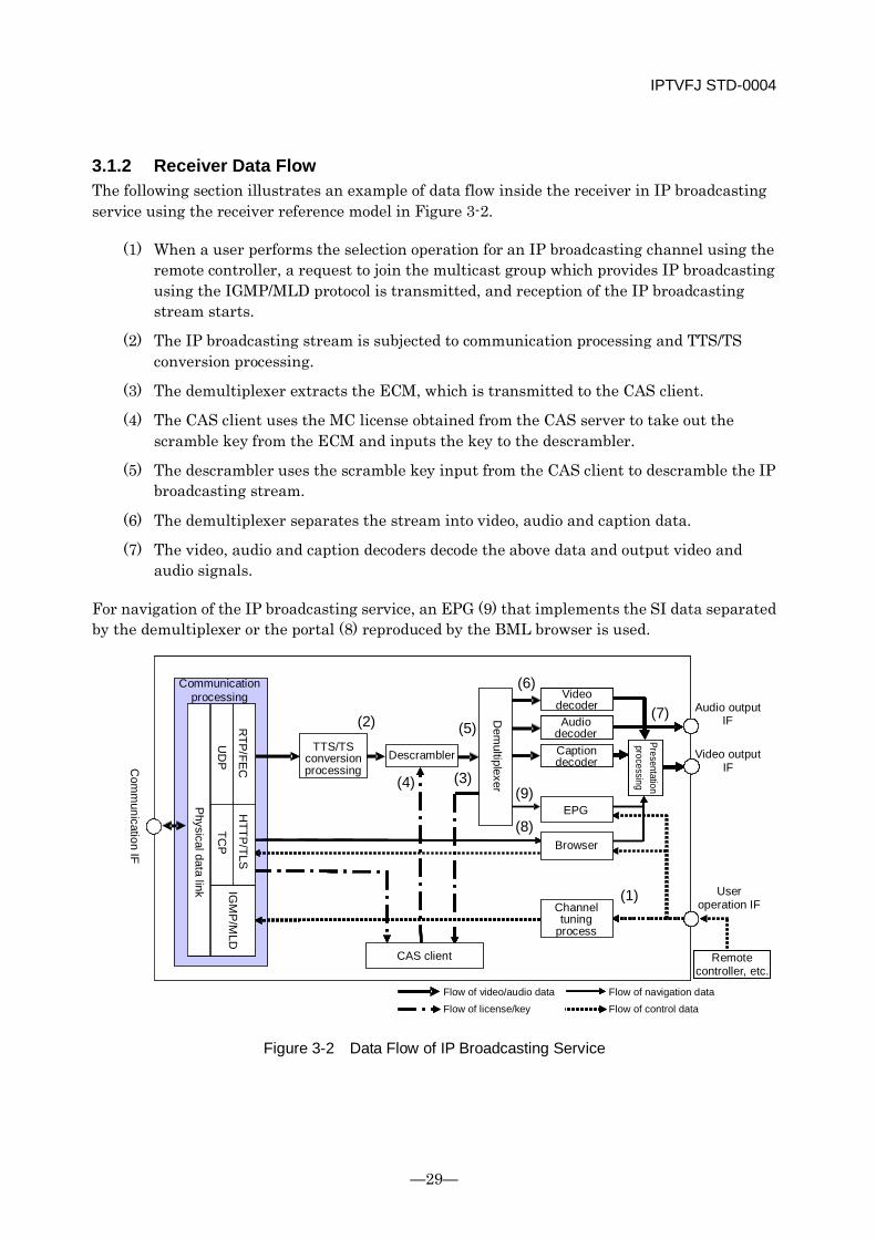
IPTVFJ STD-0004
—29—
3.1.2 Receiver Data Flow The following section illustrates an example of data flow inside the receiver in IP broadcasting service using the receiver reference model in Figure 3-2.
(1) When a user performs the selection operation for an IP broadcasting channel using the remote controller, a request to join the multicast group which provides IP broadcasting using the IGMP/MLD protocol is transmitted, and reception of the IP broadcasting stream starts.
(2) The IP broadcasting stream is subjected to communication processing and TTS/TS conversion processing.
(3) The demultiplexer extracts the ECM, which is transmitted to the CAS client.
(4) The CAS client uses the MC license obtained from the CAS server to take out the scramble key from the ECM and inputs the key to the descrambler.
(5) The descrambler uses the scramble key input from the CAS client to descramble the IP broadcasting stream.
(6) The demultiplexer separates the stream into video, audio and caption data.
(7) The video, audio and caption decoders decode the above data and output video and audio signals.
For navigation of the IP broadcasting service, an EPG (9) that implements the SI data separated by the demultiplexer or the portal (8) reproduced by the BML browser is used.
Figure 3-2 Data Flow of IP Broadcasting Service
UDP
TCP
UDP
TCP
UDP
TCP
UDP
TCP
Communication processing
Physical data link
UD
P
RTP
/FEC
TCP
HTTP
/TLS
IGM
P/M
LD
TTS/TS conversion processing
Descrambler
Dem
ultiplexer
Video decoder Audio
decoder Caption decoder
Presentation processing
Audio output IF
EPG
Browser
Video output IF
Channel tuning
process
CAS client
User operation IF
Remote controller, etc.
Flow of video/audio data Flow of navigation data Flow of license/key Flow of control data
(2) (5)
(4) (3)
(6)
(9)
(8)
(7)
(1)
Com
munication IF
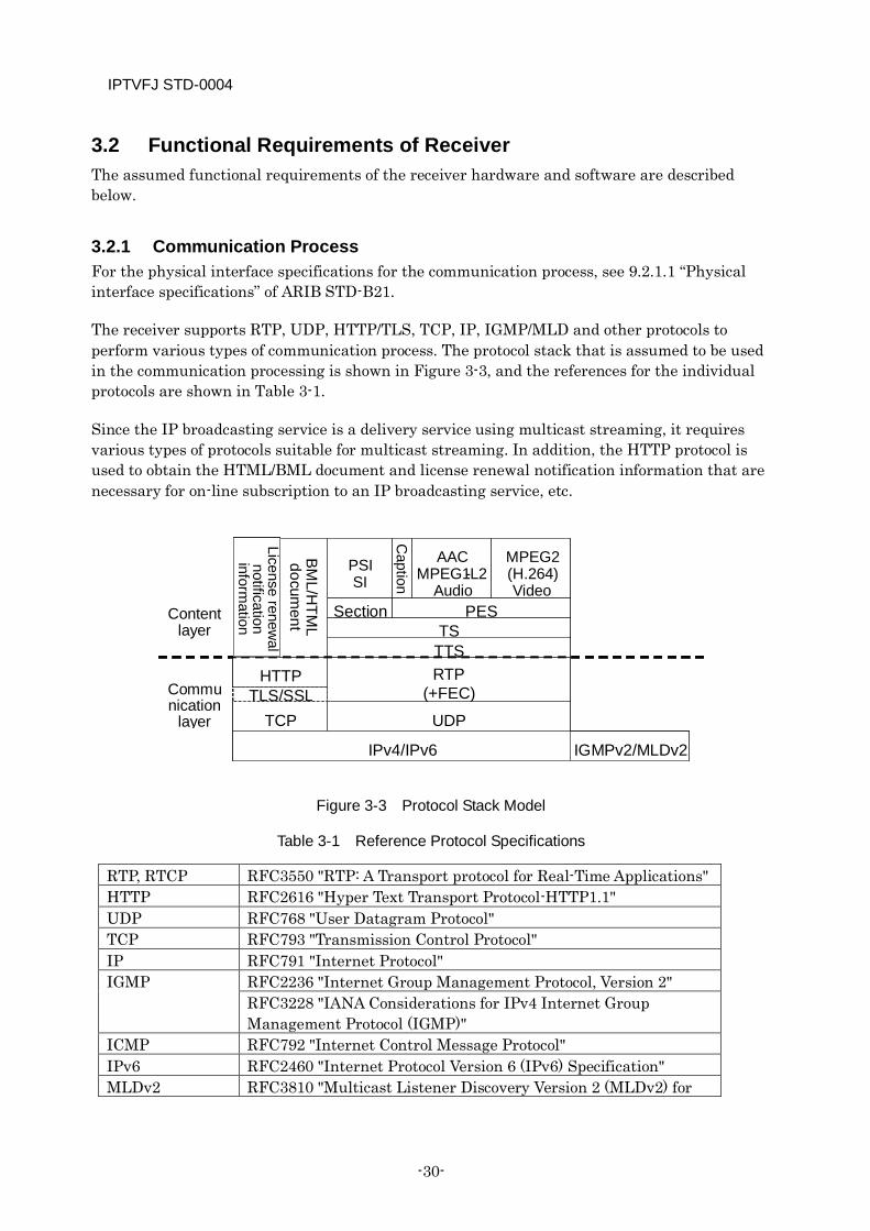
IPTVFJ STD-0004
-30-
3.2 Functional Requirements of Receiver The assumed functional requirements of the receiver hardware and software are described below.
3.2.1 Communication Process For the physical interface specifications for the communication process, see 9.2.1.1 “Physical interface specifications” of ARIB STD-B21.
The receiver supports RTP, UDP, HTTP/TLS, TCP, IP, IGMP/MLD and other protocols to perform various types of communication process. The protocol stack that is assumed to be used in the communication processing is shown in Figure 3-3, and the references for the individual protocols are shown in Table 3-1.
Since the IP broadcasting service is a delivery service using multicast streaming, it requires various types of protocols suitable for multicast streaming. In addition, the HTTP protocol is used to obtain the HTML/BML document and license renewal notification information that are necessary for on-line subscription to an IP broadcasting service, etc.
Figure 3-3 Protocol Stack Model
Table 3-1 Reference Protocol Specifications
RTP, RTCP RFC3550 "RTP: A Transport protocol for Real-Time Applications" HTTP RFC2616 "Hyper Text Transport Protocol-HTTP1.1" UDP RFC768 "User Datagram Protocol" TCP RFC793 "Transmission Control Protocol" IP RFC791 "Internet Protocol" IGMP RFC2236 "Internet Group Management Protocol, Version 2"
RFC3228 "IANA Considerations for IPv4 Internet Group Management Protocol (IGMP)"
ICMP RFC792 "Internet Control Message Protocol" IPv6 RFC2460 "Internet Protocol Version 6 (IPv6) Specification" MLDv2 RFC3810 "Multicast Listener Discovery Version 2 (MLDv2) for
IPv4/IPv6 IGMPv2/MLDv2
TCP UDP TLS/SSL
HTTP RTP (+FEC)
TTS TS
PES Section
MPEG2 (H.264) Video
AAC MPEG1 - L2
Audio PSI SI
IPv4/IPv6 IGMPv2/MLDv2
TCP UDP TLS/SSL
HTTP RTP (+FEC)
TTS TS
PES Section
MPEG2 (H.264) Video
AAC MPEG1 - L2
Audio PSI SI
IPv4/IPv6 IGMPv2/MLDv2
TCP UDP TLS/SSL
HTTP RTP (+FEC)
TTS TS
PES Section
MPEG2 (H.264) Video
AAC MPEG1 - L2
Audio PSI SI
IPv4/IPv6 IGMPv2/MLDv2
TCP UDP TLS/SSL
HTTP RTP (+FEC)
TTS TS
PES Section
MPEG2 (H.264) Video
AAC MPEG1 - L2
Audio
Caption
PSI SI
BML/H
TML
document
Content layer
Communication
layer
License renewal
notification inform
ation
IPTVFJ STD-0004
—31—
IPv6" ICMPv6 RFC4443 "Internet Control Message Protocol (ICMPv6) for the
Internet protocol Version 6 (IPv6) Specification" RFC4291 "IP Version 6 Addressing Architecture"
3.2.1.1 FEC FEC (Forward Error Correction) is effective to minimize the influence of packet loss, which can occur on the network. By incorporating FEC function, the receiver can ensure stable streaming quality.
Incorporating FEC in the receiver is optional. When used, the following requirements shall be met. A receiver without FEC should view service content by ignoring the FEC packet and receiving only the media packet.
For the FEC specifications, see 4.3.1 of these Specifications.
The FEC system shall be Pro-MPEG FEC CoP3. However, some other FEC system may also be used at the same time.
From the standpoint of implementing stable playback for prolonged periods (about one week or so), it is recommended that the receiver should support at least Pro-MPEG 1D FEC.
The FEC systems that are used in IP broadcasts are notified to the receiver by the IP distribution system descriptor of the NIT.
From among FEC systems notified to the receiver, the receiver shall select the FEC that is on the highest order in the notification and supported by the receiver, and use it in the decoding process.
If no FEC system is notified to the receiver, the receiver judges that the FEC function at the transmitting side has been turned off. In this case, the receiver should receive only the media packet for viewing the contents.
3.2.2 Video/Audio Decoding Process and Output Concerning the video decoding process of the receiver and the video output format, see 6.1.1 and 6.1.2 under 6.1 “Video decoding process and output signals” of ARIB STD-B21 for ISO/IEC 13818-2 [MPEG-2]. For ISO/IEC 14496-10 [H264|MPEG-4 AVC], see [Appendix A] of these Specifications.
Concerning the audio decoding process of the receiver and the audio output format, see 6.2 “Audio decoding process and output” of ARIB STD-B21 and Appendix 4 “Down-mix processing in the AAC decoder” of ARIB STD-B21 for ISO/IEC 13818-7 Audio [MPEG2 AAC]. For ISO/IEC 11172-3 Audio [MPEG1 Audio], see 5.1.2.1 of these Specifications.
IPTVFJ STD-0004
-32-
3.2.3 High-speed Digital Interface When the receiver is equipped with a high-speed digital interface, see Chapter 9 “Specifications for High-speed Digital Interfaces” of ARIB STD-B21 and Appendix 2 “High-speed Digital Interface” of ARIB STD-B21.
3.2.3.1 Restriction on Output of Partial TS During output of an IP broadcasting program, components which cannot be scrambled should not be output.
3.2.3.2 PSI/SI Table Operational Specifications for Partial TS Output In order to allow for the connection of an MPEG stream recorder to the receiver, specifications of partial TS transmitted from/to the receiver via a high-speed digital interface shall be defined. For details, see 3.3.1 of these Specifications.
3.2.3.3 IEEE1394 Control Command See ARIB STD-B21.
3.2.4 IP Interface Specifications When the receiver is equipped with an IP interface as a high-speed digital interface, see 9.2 “IP interface specifications” of ARIB STD-B21 and Appendix 2 “High-speed digital interfaces” of ARIB STD-B21.
For a detailed description of IP interface operation, see 3.3.3 of these Specifications.
When a wireless LAN is used, there are concerns that some device which is not recognized by the user may attempt to connect to the LAN. When the receiver is equipped with an IP interface, therefore, consideration shall be given to preventing the user from being disturbed by such attempts.
3.2.5 Copy Control Concerning copy control, the receiver shall, as a rule, implement the control based on the license in the CAS system as defined in Chapter 6 of these Specifications.
Specifically, in the copy control in IP broadcasts, the output control information that is contained in the ECM defined in 6.3.8 of these Specifications and in the applicable CAS system shall be used.
The above output control information contains control information that corresponds to the various types of control information that make up the digital copy control descriptor and content usage descriptor. In the following paragraphs, the control information used in various types of output control shall be referred to as corresponding to the appropriate control information name in the above descriptors.
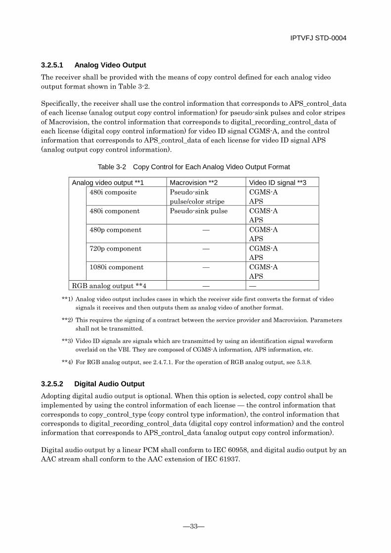
IPTVFJ STD-0004
—33—
3.2.5.1 Analog Video Output The receiver shall be provided with the means of copy control defined for each analog video output format shown in Table 3-2.
Specifically, the receiver shall use the control information that corresponds to APS_control_data of each license (analog output copy control information) for pseudo-sink pulses and color stripes of Macrovision, the control information that corresponds to digital_recording_control_data of each license (digital copy control information) for video ID signal CGMS-A, and the control information that corresponds to APS_control_data of each license for video ID signal APS (analog output copy control information).
Table 3-2 Copy Control for Each Analog Video Output Format
Analog video output **1 Macrovision **2 Video ID signal **3 480i composite Pseudo-sink
pulse/color stripe CGMS-A APS
480i component Pseudo-sink pulse CGMS-A APS
480p component — CGMS-A APS
720p component — CGMS-A APS
1080i component — CGMS-A APS
RGB analog output **4 — —
**1) Analog video output includes cases in which the receiver side first converts the format of video signals it receives and then outputs them as analog video of another format.
**2) This requires the signing of a contract between the service provider and Macrovision. Parameters shall not be transmitted.
**3) Video ID signals are signals which are transmitted by using an identification signal waveform overlaid on the VBI. They are composed of CGMS-A information, APS information, etc.
**4) For RGB analog output, see 2.4.7.1. For the operation of RGB analog output, see 5.3.8.
3.2.5.2 Digital Audio Output Adopting digital audio output is optional. When this option is selected, copy control shall be implemented by using the control information of each license — the control information that corresponds to copy_control_type (copy control type information), the control information that corresponds to digital_recording_control_data (digital copy control information) and the control information that corresponds to APS_control_data (analog output copy control information).
Digital audio output by a linear PCM shall conform to IEC 60958, and digital audio output by an AAC stream shall conform to the AAC extension of IEC 61937.
IPTVFJ STD-0004
-34-
3.2.5.3 High-speed Digital Interface Output A high-speed digital interface is optional. When this option is selected, the following conditions shall be met.
Copy control shall be implemented using the control information that corresponds to copy_control_type and the control information that corresponds to digital_recording_control_data, of each license.
The copyright protection system specified by service providers shall be DTCP. When DTCP is used, the DTCP_descriptor shall be inserted. For details, see the DTCP Specifications.
When only audio streams are output using a high-speed digital interface in accordance with serial interface specifications, the following conditions shall be met.
The IEC 60958 conformant format (includes the IEC 61937 conformant format) of IEC 61883-6 shall be applied.
Channel_status to be embedded in the IEC 60958 conformant format of IEC 61883-6 shall be set in accordance with digital_recording_control_data in the digital copy control descriptor.
Copy control shall be implemented by using the control information corresponding to copy_control_type and the control information corresponding to digital_recording_control_type, of the license.
The copyright protection system specified by service providers shall be DTCP.
When DTCP is used, the DTCP_descriptor shall be inserted. For details, see the DTCP Specifications.
3.2.5.4 Digital Video Output When a receiver equipped with DVI outputs contents, the copy of which is limited or the protection of which is specified, those contents shall be properly protected in accordance with the HDCP Specifications. For operation details, see 6.3.8 of these Specifications.
3.2.5.5 Digital AV Output When a receiver equipped with HDMI outputs contents, the copy of which is limited or the protection of which is specified, those contents shall be properly protected in accordance with the HDCP Specifications. For operation details, see 6.3.8 of these Specifications.
3.2.5.6 Removable Recording Medium When the receiver records IP services that it receives on a removable recording medium, the Specifications defined in 6.3.8 of these Specifications shall be followed.
IPTVFJ STD-0004
—35—
3.2.6 Output Terminals
3.2.6.1 RGB Analog Terminal Providing a VGA terminal is optional. When this option is selected, it is necessary to provide a connector which conforms to Section 4 “Physical Connections” of the Enhanced Display Data Channel Standard (Version 1) issued by VESA and to output signals in a format which conforms to Section 2 “VESA Video Signal Definition” of the Video Signal Standard (Version 1, Rev. 1) issued by VESA.
Providing a DVI analog output terminal is optional. When this option is selected, it is recommended that a connector which conforms to Section 5 “Physical Interconnect Specifications” of the Digital Visual Interface DVI (Revision 1.0) issued by DDWG be provided. The terminal shall output signals in a format which conforms to 2.5 “Analog” of Section 2 “Architectural Requirements” of the Digital Visual Interface DVI (Revision 1.0).
For operation of RGB analog output, see 3.4.2 of these Specifications.
3.2.6.2 Digital Video Terminal Providing a DVI terminal is optional. When this option is selected, it is recommended that a connector which conforms to Section 5 “Physical Interconnect Specifications” of the Digital Visual Interface DVI (Revision 1.0) issued by DDWG be provided. The terminal shall output signals in a format which conforms to Section 2 “Architectural Requirements” of the Digital Visual Interface DVI (Revision 1.0).
For the access control system, see Chapter 6 of these Specifications. For the protection of contents, see 6.3.8 of these Specifications.
3.2.6.3 Digital AV Output Terminal Providing an HDMI terminal is optional. When this option is selected, the terminal shall conform to the High-Definition Multimedia Interface Specification issued by HDMI Licensing, LLC.
For the access control system, see Chapter 6 of these Specifications. For the protection of contents, see 6.3.8 of these Specifications.
3.2.7 Service channel Selection The basic operation involved in service channel selection is described below. It should be noted that the description given below does not preclude any other method of channel selection: the method of channel selection is basically left to each individual receiver manufacturer.
The channel selection operation is performed according to the PSI. An example of the selection process is shown in Figure 3-4.
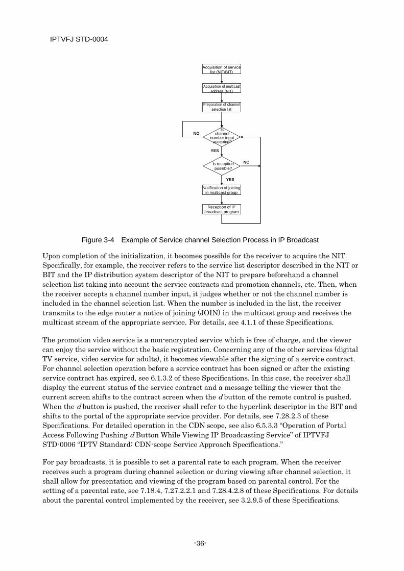
IPTVFJ STD-0004
-36-
Figure 3-4 Example of Service channel Selection Process in IP Broadcast
Upon completion of the initialization, it becomes possible for the receiver to acquire the NIT. Specifically, for example, the receiver refers to the service list descriptor described in the NIT or BIT and the IP distribution system descriptor of the NIT to prepare beforehand a channel selection list taking into account the service contracts and promotion channels, etc. Then, when the receiver accepts a channel number input, it judges whether or not the channel number is included in the channel selection list. When the number is included in the list, the receiver transmits to the edge router a notice of joining (JOIN) in the multicast group and receives the multicast stream of the appropriate service. For details, see 4.1.1 of these Specifications.
The promotion video service is a non-encrypted service which is free of charge, and the viewer can enjoy the service without the basic registration. Concerning any of the other services (digital TV service, video service for adults), it becomes viewable after the signing of a service contract. For channel selection operation before a service contract has been signed or after the existing service contract has expired, see 6.1.3.2 of these Specifications. In this case, the receiver shall display the current status of the service contract and a message telling the viewer that the current screen shifts to the contract screen when the d button of the remote control is pushed. When the d button is pushed, the receiver shall refer to the hyperlink descriptor in the BIT and shifts to the portal of the appropriate service provider. For details, see 7.28.2.3 of these Specifications. For detailed operation in the CDN scope, see also 6.5.3.3 “Operation of Portal Access Following Pushing d Button While Viewing IP Broadcasting Service” of IPTVFJ STD-0006 “IPTV Standard: CDN-scope Service Approach Specifications.”
For pay broadcasts, it is possible to set a parental rate to each program. When the receiver receives such a program during channel selection or during viewing after channel selection, it shall allow for presentation and viewing of the program based on parental control. For the setting of a parental rate, see 7.18.4, 7.27.2.2.1 and 7.28.4.2.8 of these Specifications. For details about the parental control implemented by the receiver, see 3.2.9.5 of these Specifications.
Acquisition of service list (NIT/BIT)
Preparation of channel selection list
Is reception possible?
Reception of IP broadcast program
Acquisition of multicast address (NIT)
Notification of joining in multicast group
YES
NO
Is channel
number input accepted?
YES
NO
IPTVFJ STD-0004
—37—
The above differences between services can be seen from service_type described in the service list descriptor in the NIT, etc. For details, see 7.6.1 of these Specifications.
It should be noted that the SI-exclusive TS is intended only to supply specific information, such as EIT [schedule], to the receiver, and that it is not directly involved in channel selection by the viewer.
For any unusual service conditions which the receiver can easily perceive, such as the suspension of broadcast of a selected program, the receiver shall display a message advising this to the viewer. For the definition of “suspension of broadcast,” see 5.3.4 of these Specifications.
3.2.7.1 Method of Channel Selection The basic method of channel selection shall be direct selection by the input of a three-digit channel number. However, out of consideration for viewer convenience, a better user interface shall be provided, which includes using the channel UP/DOWN button, one-touch channel selection, and channel selection from the EPG.
In addition, the receiver shall display the relevant information about the selected channel (three-digit channel number, service name, logo, etc.) by means of banner indication, etc. upon channel selection.
3.2.7.1.1 Direct Channel Selection by Inputting a Three-digit Channel Number
When the viewer pushes any number key, the receiver enters channel selection mode to allow input of a three-digit channel number.
If the input of a three-digit channel number is not completed within a prescribed time (about 5 seconds), the screen returns to normal mode, displaying the current channel information.
When a three-digit channel number is input within the prescribed time, the receiver judges whether or not the channel is included in the receivable service list it has already prepared. If the channel is not found in the list, the receiver displays a message “Channel not found.”
When the channel is found in the list, the receiver performs the channel selection processing, sets the last mode, and displays the channel information after channel selection.
3.2.7.1.2 Channel Selection via the Channel UP/DOWN Button
Each time the viewer pushes the channel UP/DOWN button, a channel is displayed in the order indicated by service_id (3-digit channel number).
When the UP button is pushed, the receiver selects the service immediately above the channel number that is currently selected. Note, however, that if the currently selected channel number is the largest one in the list, the receiver selects the smallest channel number.
When the DOWN button is pushed, the receiver selects the service immediately under the channel number that is currently selected. Note, however, that if the currently selected
IPTVFJ STD-0004
-38-
channel number is the smallest one in the list, the receiver selects the largest channel number.
After selection of a channel, the receiver sets the last mode and displays the channel information.
3.2.7.1.3 One-touch Channel Selection
Concerning the allocation of a channel selection function to a specific button, no special rules are set on the factory setting of the receiver.
After selection of a channel, the receiver sets the last mode and displays the channel information.
3.2.7.1.4 Channel Selection via EPG
After selection of a channel, the receiver sets the last mode and displays the channel information.
3.2.7.2 Switching Between Networks, etc. In IP broadcasting, two or more IP broadcasting networks may exist on a single CDN. Similarly, on a single IP broadcasting network, there may be two or more service providers. Such network can be identified by the network_id in the NIT, etc. and service providers can be identified by the broadcaster_id in the BIT. Although any receiver can connect to a single CDN at a time, it shall be provided with means of selecting each of the available networks on the basis of the PSI/SI information and the information on the IP broadcasting networks that exist on the CDN (in the CDN scope, the CDN configuration information and PF configuration information that the receiver obtains).
In addition, it is assumed that some receivers will be equipped with the capability to receive terrestrial digital broadcasts, BS digital broadcasts and other broadcasting media as well. Those receivers shall be provided with means of switching between networks.
3.2.7.3 Other Matters to be Heeded Even after the receiver has selected a channel, it periodically receives from the edge router
an inquiry about the status of joining the multicast address group. It should be noted that multicast delivery might be stopped if the receiver fails to respond to the inquiry within a prescribed time.
When switching quickly between channels, AV may stream before switching flow into the communication network, in excess of the upper limit of the NW bandwidth (includes home networks). If this happens, temporary loss of data, etc. is possible. In view of this, it is desirable that the receiver be equipped with a function to limit the channel-switching speed.
In IP broadcasting, unlike ordinary broadcasting, the receiver must not always be kept ready for reception. Rather, from the standpoint of effective utilization of the access network band, it is desirable that the receiver should leave the multicast of the IP
IPTVFJ STD-0004
—39—
broadcasting service of the selected channel and enter into the state in which it is not receiving any IP broadcast unless it is playing or recording some content.
3.2.8 Switching between ESes Although the function defined here is in itself indispensable, the method of implementing it shall be left to each individual receiver.
3.2.8.1 Default ES For the method of selecting the first ES to be decoded (default ES) from among more than one ES if it is not specified when the receiver selects a service, see 5.2.1.4 of these Specifications.
3.2.8.2 Selection of Audio ES There are cases in which more than one audio ES is transmitted to the receiver at a time. Therefore, the receiver shall be equipped with a user interface which permits selecting the desired ES. It is desirable that the user interface should permit the viewer to select the default ES during channel switching and to cyclically switch between the selection of Main/Sub and the selection of audio ES by using the Audio button of the remote controller. If the user interface is such that the viewer selects the desired audio from a menu, the receiver shall display the relevant audio information according to the text_char information in the audio component descriptor.
3.2.8.3 Selection of Caption A maximum of one caption ES may exist. Concerning the caption ES, the receiver shall permit selecting either “Do not display caption” or “Display one of languages existing in caption ES.” The former shall be the default. It is desirable that the viewer should be able to cyclically switch between them by using the Caption button of the remote controller. If the user interface is such that the viewer selects the caption ES from a menu, the receiver shall display the language information according to the information described by selector_byte in the data content descriptor.
3.2.9 EPG The EPG functions (program table display, program search, program reservation, etc.) using SI and the EPG user interface shall, as a rule, be left to each individual receiver manufacturer. However, in consideration of the viewer’s convenience and to facilitate the production of SI, the following specifications and guidelines are provided.
3.2.9.1 Modeling of EPG Functions
3.2.9.1.1 EPG Screen
It is assumed as a screen model (e.g., program table in the image of radio/TV column of general newspaper) to obtain the program information about each IP broadcasting service from the
IPTVFJ STD-0004
-40-
SI-exclusive TS for EPG, store the program information in the receiver’s memory, and display the most detailed information about all the IP broadcasting services.
3.2.9.1.2 EPG Information that The Receiver Needs to Obtain
The EPG screen in IP broadcasting is displayed by obtaining and using the configuration information file, EIT [schedule], EIT [p/f] and logo information. The receiver obtains these pieces of information as described below.
(a) EIT [schedule]
The EIT [schedule] that describes program information is transmitted by an SI-exclusive TS for EPG. For details about the EIT transmission operation, see 7.11.1.3 of these Specifications.
In the CDN scope, the receiver obtains the SI-exclusive TS for EPG by selecting the appropriate SI server via the multicast address, etc. described in the SI server information prepared for each platform in the configuration information file that is obtained from the PF configuration information server.
It is desirable that the receiver should select the SI server at least once a day to update the program information.
(b) EIT [p/f]
The present and following programs of the channel that is currently selected can be obtained from EIT [p/f] too. By referring to EIT [p/f] successively, it is possible to reflect on the EPG screen any change in the program information due to flexible program changes, etc. The method of reflection shall be left to each individual receiver manufacturer.
(c) Logo Information
Concerning the acquisition of logo information, it shall, as a rule, be left to each individual receiver manufacturer.
In the CDN scope, if logo information is necessary for presenting a logo to the EPG, the receiver shall use the HTTP protocol to obtain from the logo data server the logo information according to the logo server information that is prepared for each platform in the configuration information file on the PF configuration information server.
If the version number described in the logo file name of the logo server information has been updated from the logo file obtained previously, the receiver shall obtain the new logo data and replace the old logo data with it before presenting the logo to the EPG.
3.2.9.1.3 Specifications and Guidelines on EPG
Arrangements shall be made to prevent the program selection operation from being impeded by abnormal transmission of the SI table. Even if the SI information is not normally transmitted to the receiver, the receiver shall be able to perform the channel selection and display operations using the PSI information.

IPTVFJ STD-0004
—41—
When displaying a list of channels or program information, it is desirable that the receiver should display the currently selected (received) channel at the position on the screen that stands out most.
When the receiver accumulates SI, it is possible that the receiver provides the EPG with obsolete information because of the difference between the time at which SI is accumulated and the current time. Therefore, it is desirable that in the receiver instruction manual, etc., a note should be given to the effect that the program is subject to change without prior notice and that there might be some discrepancy between the contents of the EPG and those of the actual broadcast.
The default character string when the text_char area in the audio component descriptor is omitted shall be ‘audio.’ In the case of dual mono, however, the default character string shall be ‘first audio CR (Carriage Return) second audio.’
It is desirable that the receiver should have the function of obtaining the latest program information about all the receivable services at the request of the viewer while the receiver power supply is on. In executing this function, however, it is necessary to let the viewer understand that updating all the program information takes a long time. Besides, arrangements shall be made to prevent the function from being executed thoughtlessly. While the receiver is obtaining program information, it may interrupt the reception of audio/video signals.
3.2.9.2 Program Table The receiver must not fail to display information about a specific service provider or channel even though it can normally obtain the SI.
It is desirable that the EPG should be independently displayed for each individual network.
The presence of every program offered must be indicated in some form regardless of the program length.
When there are long programs, including ones that last for more than 24 hours, it must be possible for the viewer to recognize the presence thereof even if the EPG displays any time belt during the broadcast.
When the program table is displayed in the image of the radio/TV column of a newspaper, it is desirable that it should be displayed in the same format as in the newspaper (10 double-byte characters per line).
In the program table (program titles + program captions), multi-hour programs shall each be displayed within 40 characters. However, the number of characters may be reduced to 20 (20 or less for programs which last for 30 minutes or less) if the available display space is limited.
The program table shall be displayed in such a manner that the viewer can see whether the service contract for each individual channel has been signed or not.
IPTVFJ STD-0004
-42-
It is desirable that the receiver should be able to display attributes of programs. Here, the term “attributes” refers to the video mode, audio mode, caption, digital copy permitted/prohibited, parental information, etc. which are transmitted by SI.
It is desirable that the channel scroll through the program table should be loop scroll.
It is desirable that the receiver should present EPG in such a manner that the viewer can identify the individual service providers to which the channels displayed belong.
In the display of EPG on IP broadcasts, whether to display EPG for each individual service provider or for all service providers is left to each receiver manufacturer. For non-scrambled channels at least, it is desirable that the receiver should be able to present EPG information even when the basic registration of the service providers associated with them has not been made.
In the display of program information in EPG, it is desirable that the contracted program information should be displayed preferentially.
As a method of displaying EPG, the receiver may display reduced IP broadcasting video on the EPG screen or α-blend the EPG screen on the IP broadcasting video. When displaying the EPG screen, the receiver may interrupt the play of the IP broadcast or VOD program that is being viewed.
When the EPG function is invoked during pseudo-data broadcast (display in L-shaped window) or portal display, the current screen display may be interrupted.
The display of service provider logos, platform provider logos and channel logos on the program table screen is left to each receiver manufacturer. When displaying information about service providers, platform providers and channels, it is desirable that those logos should be displayed at the same time. It should be noted, however, that if the receiver cannot obtain those logos because of network conditions, etc., the presentation of logos may be omitted. In this case, the alternative method of display is left to each receiver manufacturer.
When displaying channel logos in the EPG, it is desirable that the receiver should present those channels which are presented on the EPG screen equally.
3.2.9.3 Program Search It is desirable that the receiver should have the function of searching for programs by program genre transmitted by using content_nibble_1 (major classification) and content_nibble_2 (intermediate classification) of content_descriptor. When this function is provided, the receiver shall allow program searches even by the major classification information alone.
It is desirable that the program search function should also be applicable to the program genre of user_nibble extended specially for IP broadcasts.
IPTVFJ STD-0004
—43—
3.2.9.4 Display of Program Information In designing the display layout of detailed program information, guidelines on how the information should be displayed on the receiver are required. When the receiver displays detailed program information, the number of characters per line shall, as a rule, be 20 in double-byte characters.
* The above number of characters corresponds to an area of 480 horizontal dots (one-half of the horizontal width) when 24-dot fonts are used at the character pattern definition (960*540) in HD.
3.2.9.5 Parental Control In IP broadcasting, there is the possibility that programs for which a parental rate is set will be broadcast. Therefore, it is desirable that consideration should be given to implementing the parental control in EPG, program search and program information display as well.
In displaying the EPG, it is desirable to implement the parental control in accordance with Table 3-3.
The parental control of video services for adults with a parental rating of 0x11 (R-20) shall be operated on a channel basis, not on a program basis. When a parental rate is set at the receiver, the specific user interface for resetting it in the EPG shall be left to each receiver manufacturer.
At the receiver, the EPG shall operate according to the parental control conditions set on the initialization screen.
When displaying a program genre on the program search screen, etc., parental control shall not be defined.
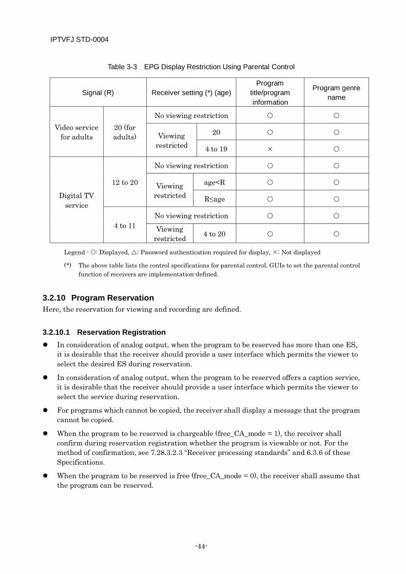
IPTVFJ STD-0004
-44-
Table 3-3 EPG Display Restriction Using Parental Control
Signal (R) Receiver setting (*) (age) Program
title/program information
Program genre name
Video service for adults
20 (for adults)
No viewing restriction
Viewing restricted
20
4 to 19
Digital TV service
12 to 20
No viewing restriction
Viewing restricted
age<R
R≤age
4 to 11 No viewing restriction
Viewing restricted 4 to 20
Legend - : Displayed, : Password authentication required for display, : Not displayed
(*) The above table lists the control specifications for parental control. GUIs to set the parental control function of receivers are implementation-defined.
3.2.10 Program Reservation Here, the reservation for viewing and recording are defined.
3.2.10.1 Reservation Registration In consideration of analog output, when the program to be reserved has more than one ES,
it is desirable that the receiver should provide a user interface which permits the viewer to select the desired ES during reservation.
In consideration of analog output, when the program to be reserved offers a caption service, it is desirable that the receiver should provide a user interface which permits the viewer to select the service during reservation.
For programs which cannot be copied, the receiver shall display a message that the program cannot be copied.
When the program to be reserved is chargeable (free_CA_mode = 1), the receiver shall confirm during reservation registration whether the program is viewable or not. For the method of confirmation, see 7.28.3.2.3 “Receiver processing standards” and 6.3.6 of these Specifications.
When the program to be reserved is free (free_CA_mode = 0), the receiver shall assume that the program can be reserved.
IPTVFJ STD-0004
—45—
When a parental rate is set for a program to be reserved, the receiver shall register the reservation only when the program can be presented and viewed under the parental controls. For the setting of parental rates, see 7.18.4 of these Specifications.
3.2.10.2 Confirmation of Reserved Program The receiver shall have a user interface which permits the viewer to confirm the program
that has been reserved.
It is desirable that the receiver should have the function of displaying a list of reserved programs.
The receiver shall permit the viewer to cancel any of the programs that have been reserved.
3.2.10.3 Execution of Reservation The reservation operation shall be executed according to EIT [p/f] in the TS that transmits
the reserved program. When programs are continuously reserved across two or more channels by EPG reservation, there is the possibility that the reservations partly overlap at the time of switching from one program to another. In this case, which program is to be given priority depends on how the receiver is implemented. It is desirable, however, that the receiver should display the overlap of reservations and leave the choice to the viewer.
The registration of program reservation shall be automatically eliminated when the program is finished.
If the starting time and/or the ending time of a reserved program is changed, it is desirable that the receiver should execute the reservation according to the change. For changing the time of a reserved program, see 7.17 of these Specifications.
When executing the reservation of a program for which a parental rate is set, the reservation shall be executed in the same way as for programs without a parental rate since the program has been subjected to parental control during reservation registration.
The receiver operation in the case of contention for the receiver resource, such as the execution of a reservation during the execution of some other service, shall be left to each receiver manufacturer.

IPTVFJ STD-0004
-46-
3.3 Supplement
3.3.1 Specifications of PSI/SI Operation for Partial TS Output The specifications of PSI/SI operation for the partial TS output of IP broadcasting are described below.
3.3.1.1 Definitions of Tables/Descriptors
Table types and identification
When exporting an IP broadcast in the form of partial TS, the PSI/SI tables described in Table 3-4 shall be inserted. For details of each table, see ARIB STD-B10 and STD-B21.
Table 3-4 PSI/SI Tables Used in IP Broadcasting
Table name Outline of function Program Association Table (PAT) This table specifies the packet identifier of the
TS packet that transmits the PMT associated with partial TS.
Program Map Table (PMT) This table specifies the packet identifier of the TS packet that transmits coded signals which constitute a broadcast program.
Discontinuity Information Table (DIT) This table indicates the point of change at which the service information on the program transmitted by partial TS might be discontinuous.
Selection Information Table (SIT) This table indicates the information about the program transmitted by partial TS.
The PID values of transport stream packets which transmit partial TS sections are shown in Table 3-5.
Table 3-5 Allocation of PID to PSI/SI
PID Table 0x0000 PAT Specified indirectly by PAT PMT 0x001E DIT 0x001F SIT
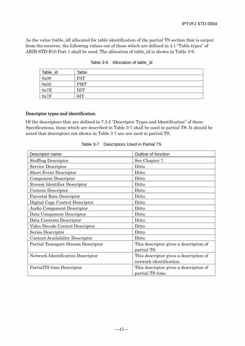
IPTVFJ STD-0004
—47—
As the value (table_id) allocated for table identification of the partial TS section that is output from the receiver, the following values out of those which are defined in 4.1 “Table types” of ARIB STD-B10 Part 1 shall be used. The allocation of table_id is shown in Table 3-6.
Table 3-6 Allocation of table_id
Table_id Table 0x00 PAT 0x02 PMT 0x7E DIT 0x7F SIT
Descriptor types and identification
Of the descriptors that are defined in 7.3.2 “Descriptor Types and Identification” of these Specifications, those which are described in Table 3-7 shall be used in partial TS. It should be noted that descriptors not shown in Table 3-7 are not used in partial TS.
Table 3-7 Descriptors Used in Partial TS
Descriptor name Outline of function Stuffing Descriptor See Chapter 7. Service Descriptor Ditto Short Event Descriptor Ditto Component Descriptor Ditto Stream Identifier Descriptor Ditto Content Descriptor Ditto Parental Rate Descriptor Ditto Digital Copy Control Descriptor Ditto Audio Component Descriptor Ditto Data Component Descriptor Ditto Data Contents Descriptor Ditto Video Decode Control Descriptor Ditto Series Descriptor Ditto Content Availability Descriptor Ditto Partial Transport Stream Descriptor This descriptor gives a description of
partial TS. Network Identification Descriptor This descriptor gives a description of
network identification. PartialTS time Descriptor This descriptor gives a description of
partial TS time.
IPTVFJ STD-0004
-48-
3.3.1.2 Operation of Common Items in The Tables
Use of version_number
Assignment of version_number
The version_number is assigned to each table independently.
The PMT to be output by partial TS may be output by using the same version_number as used in the broadcast only when the PMT used in the broadcast can be directly inserted as the PMT of the partial TS. On the other hand, as the table version_number when the receiver reconfigures PAT, DIT, SIT and PMT, the receiver may assign any number to each table as the initial version number.
Timing of change
When the broadcast PMT is directly output by partial TS, the timing of change of the version number may be the same as that in the broadcast. In the case of a table which has been reconfigured by the receiver, however, the version number shall be changed when it becomes necessary to modify the table information. For the use of version_number when the change of streams involves the insertion of DIT, see the item on DIT. When the change of streams does not involve the insertion of DIT, the delay in changing the version number against the change of streams must be made as small as possible.
Change of version
As a rule, the version_number shall be managed by the receiver, which may output any number as the initial version number. Ordinarily, version_number is incremented by 1 each time the current version is updated or revised. It should be noted, however, that in a broadcast, the version number of PMT is not always changed properly. Even in such a case, it is recommended that the PMT be output by the proper use of version_number.
When the change of streams involves the insertion of DIT too, it is recommended that the version number be incremented by 1.
Use of current_next_indicator
In all the tables that are to be output, current_next_indicator shall be set to ‘1.’ Any table in which current_next_indicator is ‘0’ shall not be output. When the receiver configures the tables, it must set ‘1’ for them.
Use of running_status
The value of running_status in SIT shall always be 0x0 (undefined) when the SIT is output.
Operation of reserved, ISO_reserved and reserved_future_use
All the bits shall be set to ‘1’ when the table is output.
3.3.1.3 Retransmission cycle (Repetition Period) of Each Table The maximum period of repetition of each table in partial TS is shown in Table 3-8.
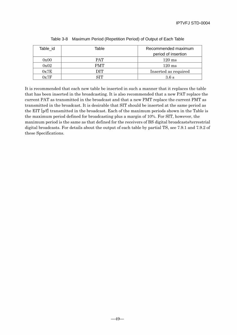
IPTVFJ STD-0004
—49—
Table 3-8 Maximum Period (Repetition Period) of Output of Each Table
Table_id Table Recommended maximum period of insertion
0x00 PAT 120 ms 0x02 PMT 120 ms 0x7E DIT Inserted as required 0x7F SIT 3.6 s
It is recommended that each new table be inserted in such a manner that it replaces the table that has been inserted in the broadcasting. It is also recommended that a new PAT replace the current PAT as transmitted in the broadcast and that a new PMT replace the current PMT as transmitted in the broadcast. It is desirable that SIT should be inserted at the same period as the EIT [p/f] transmitted in the broadcast. Each of the maximum periods shown in the Table is the maximum period defined for broadcasting plus a margin of 10%. For SIT, however, the maximum period is the same as that defined for the receivers of BS digital broadcasts/terrestrial digital broadcasts. For details about the output of each table by partial TS, see 7.9.1 and 7.9.2 of these Specifications.
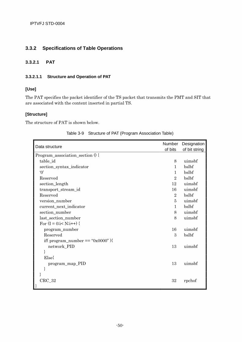
IPTVFJ STD-0004
-50-
3.3.2 Specifications of Table Operations
3.3.2.1 PAT
3.3.2.1.1 Structure and Operation of PAT
[Use]
The PAT specifies the packet identifier of the TS packet that transmits the PMT and SIT that are associated with the content inserted in partial TS.
[Structure]
The structure of PAT is shown below.
Table 3-9 Structure of PAT (Program Association Table)
Data structure Number of bits
Designation of bit string
Program_association_section () { table_id 8 uimsbf section_syntax_indicator 1 bslbf ‘0’ 1 bslbf Reserved 2 bslbf section_length 12 uimsbf transport_stream_id 16 uimsbf Reserved 2 bslbf version_number 5 uimsbf current_next_indicator 1 bslbf section_number 8 uimsbf last_section_number 8 uimsbf For (I = 0;i< N;i++) {
program_number 16 uimsbf Reserved 3 bslbf if( program_number == “0x0000” ){
network_PID 13 uimsbf } Else{
program_map_PID 13 uimsbf }
} CRC_32 32 rpchof
}
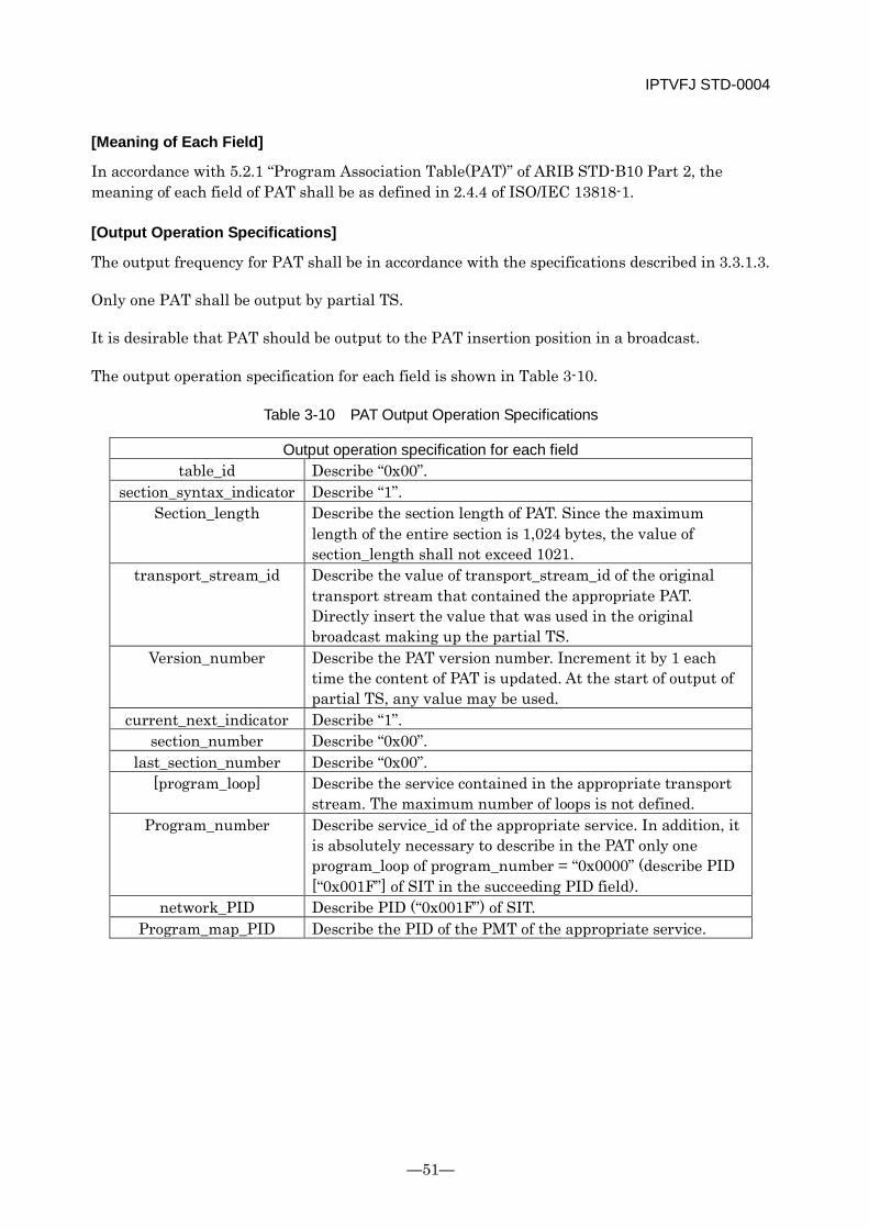
IPTVFJ STD-0004
—51—
[Meaning of Each Field]
In accordance with 5.2.1 “Program Association Table(PAT)” of ARIB STD-B10 Part 2, the meaning of each field of PAT shall be as defined in 2.4.4 of ISO/IEC 13818-1.
[Output Operation Specifications]
The output frequency for PAT shall be in accordance with the specifications described in 3.3.1.3.
Only one PAT shall be output by partial TS.
It is desirable that PAT should be output to the PAT insertion position in a broadcast.
The output operation specification for each field is shown in Table 3-10.
Table 3-10 PAT Output Operation Specifications
Output operation specification for each field table_id Describe “0x00”.
section_syntax_indicator Describe “1”. Section_length Describe the section length of PAT. Since the maximum
length of the entire section is 1,024 bytes, the value of section_length shall not exceed 1021.
transport_stream_id Describe the value of transport_stream_id of the original transport stream that contained the appropriate PAT. Directly insert the value that was used in the original broadcast making up the partial TS.
Version_number Describe the PAT version number. Increment it by 1 each time the content of PAT is updated. At the start of output of partial TS, any value may be used.
current_next_indicator Describe “1”. section_number Describe “0x00”.
last_section_number Describe “0x00”. [program_loop] Describe the service contained in the appropriate transport
stream. The maximum number of loops is not defined. Program_number Describe service_id of the appropriate service. In addition, it
is absolutely necessary to describe in the PAT only one program_loop of program_number = “0x0000” (describe PID [“0x001F”] of SIT in the succeeding PID field).
network_PID Describe PID (“0x001F”) of SIT. Program_map_PID Describe the PID of the PMT of the appropriate service.
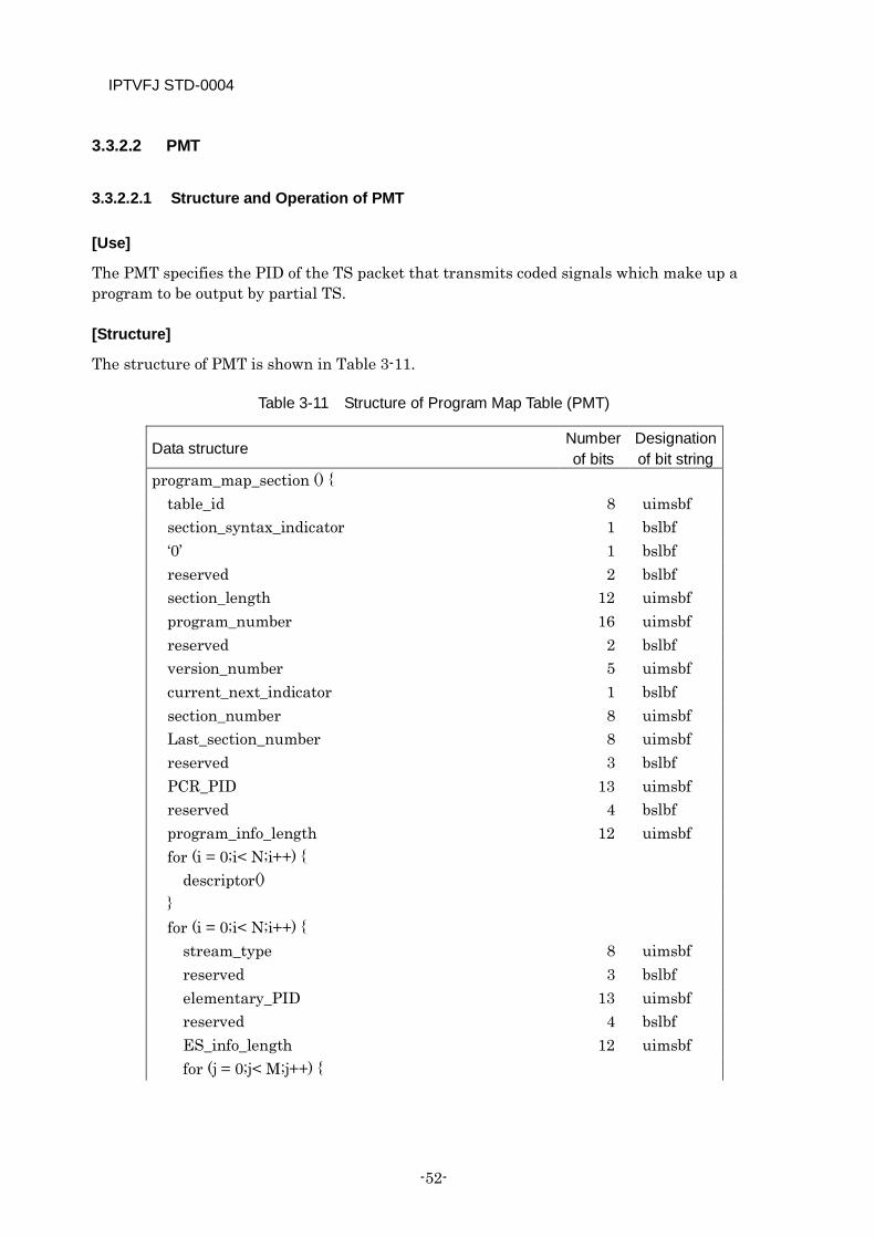
IPTVFJ STD-0004
-52-
3.3.2.2 PMT
3.3.2.2.1 Structure and Operation of PMT
[Use]
The PMT specifies the PID of the TS packet that transmits coded signals which make up a program to be output by partial TS.
[Structure]
The structure of PMT is shown in Table 3-11.
Table 3-11 Structure of Program Map Table (PMT)
Data structure Number of bits
Designation of bit string
program_map_section () { table_id 8 uimsbf section_syntax_indicator 1 bslbf ‘0’ 1 bslbf reserved 2 bslbf section_length 12 uimsbf program_number 16 uimsbf reserved 2 bslbf version_number 5 uimsbf current_next_indicator 1 bslbf section_number 8 uimsbf Last_section_number 8 uimsbf reserved 3 bslbf PCR_PID 13 uimsbf reserved 4 bslbf program_info_length 12 uimsbf for (i = 0;i< N;i++) {
descriptor() } for (i = 0;i< N;i++) {
stream_type 8 uimsbf reserved 3 bslbf elementary_PID 13 uimsbf reserved 4 bslbf ES_info_length 12 uimsbf for (j = 0;j< M;j++) {
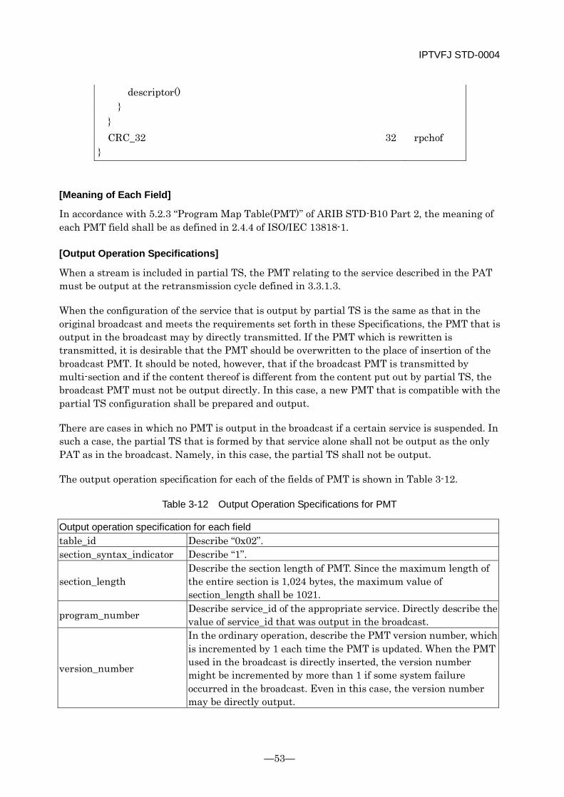
IPTVFJ STD-0004
—53—
descriptor() }
} CRC_32 32 rpchof
}
[Meaning of Each Field]
In accordance with 5.2.3 “Program Map Table(PMT)” of ARIB STD-B10 Part 2, the meaning of each PMT field shall be as defined in 2.4.4 of ISO/IEC 13818-1.
[Output Operation Specifications]
When a stream is included in partial TS, the PMT relating to the service described in the PAT must be output at the retransmission cycle defined in 3.3.1.3.
When the configuration of the service that is output by partial TS is the same as that in the original broadcast and meets the requirements set forth in these Specifications, the PMT that is output in the broadcast may by directly transmitted. If the PMT which is rewritten is transmitted, it is desirable that the PMT should be overwritten to the place of insertion of the broadcast PMT. It should be noted, however, that if the broadcast PMT is transmitted by multi-section and if the content thereof is different from the content put out by partial TS, the broadcast PMT must not be output directly. In this case, a new PMT that is compatible with the partial TS configuration shall be prepared and output.
There are cases in which no PMT is output in the broadcast if a certain service is suspended. In such a case, the partial TS that is formed by that service alone shall not be output as the only PAT as in the broadcast. Namely, in this case, the partial TS shall not be output.
The output operation specification for each of the fields of PMT is shown in Table 3-12.
Table 3-12 Output Operation Specifications for PMT
Output operation specification for each field table_id Describe “0x02”. section_syntax_indicator Describe “1”.
section_length Describe the section length of PMT. Since the maximum length of the entire section is 1,024 bytes, the maximum value of section_length shall be 1021.
program_number Describe service_id of the appropriate service. Directly describe the value of service_id that was output in the broadcast.
version_number
In the ordinary operation, describe the PMT version number, which is incremented by 1 each time the PMT is updated. When the PMT used in the broadcast is directly inserted, the version number might be incremented by more than 1 if some system failure occurred in the broadcast. Even in this case, the version number may be directly output.
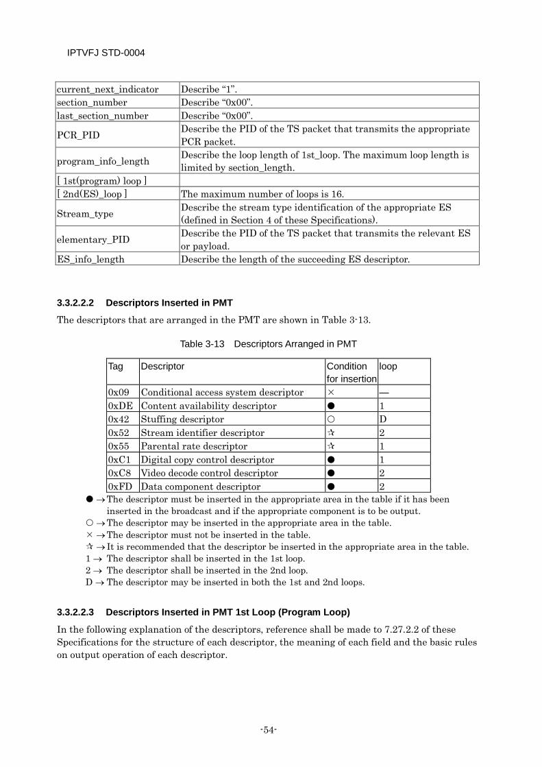
IPTVFJ STD-0004
-54-
current_next_indicator Describe “1”. section_number Describe “0x00”. last_section_number Describe “0x00”.
PCR_PID Describe the PID of the TS packet that transmits the appropriate PCR packet.
program_info_length Describe the loop length of 1st_loop. The maximum loop length is limited by section_length.
[ 1st(program) loop ] [ 2nd(ES)_loop ] The maximum number of loops is 16.
Stream_type Describe the stream type identification of the appropriate ES (defined in Section 4 of these Specifications).
elementary_PID Describe the PID of the TS packet that transmits the relevant ES or payload.
ES_info_length Describe the length of the succeeding ES descriptor.
3.3.2.2.2 Descriptors Inserted in PMT
The descriptors that are arranged in the PMT are shown in Table 3-13.
Table 3-13 Descriptors Arranged in PMT
Tag Descriptor Condition for insertion
loop
0x09 Conditional access system descriptor — 0xDE Content availability descriptor 1 0x42 Stuffing descriptor D 0x52 Stream identifier descriptor 2 0x55 Parental rate descriptor 1 0xC1 Digital copy control descriptor 1 0xC8 Video decode control descriptor 2 0xFD Data component descriptor 2
→ The descriptor must be inserted in the appropriate area in the table if it has been inserted in the broadcast and if the appropriate component is to be output.
→ The descriptor may be inserted in the appropriate area in the table. → The descriptor must not be inserted in the table. → It is recommended that the descriptor be inserted in the appropriate area in the table. 1 → The descriptor shall be inserted in the 1st loop. 2 → The descriptor shall be inserted in the 2nd loop. D → The descriptor may be inserted in both the 1st and 2nd loops.
3.3.2.2.3 Descriptors Inserted in PMT 1st Loop (Program Loop)
In the following explanation of the descriptors, reference shall be made to 7.27.2.2 of these Specifications for the structure of each descriptor, the meaning of each field and the basic rules on output operation of each descriptor.
IPTVFJ STD-0004
—55—
3.3.2.2.3.1 Digital Copy Control Descriptor
For details of this descriptor, see 7.27.2.2.2 of these Specifications.
[Use]
This descriptor is inserted when digital copy control information is indicated to all the appropriate services and/or when the maximum transmission rate is described.
[Output Operation Specifications]
When the appropriate ES is subject to digital copy control and when it has been described in the original broadcast, this descriptor must be inserted to show the various types of copy control information. If the broadcast service is a pay program (ECM is transmitted), the descriptor shall be rewritten into the value specified by the output control information of the ECM associated with the service before it is inserted.
3.3.2.2.3.2 Parental Rate Descriptor
[Use]
This descriptor describes a parental rate for a specific event.
Since this descriptor is not operated in PMT in broadcasts, it shall be prepared automatically within the receiver.
[Output Operation Specifications]
In the broadcast, the parental rate that is described in the first byte of the private_data_byte field of the 1st loop conditional access system descriptor for the appropriate event shall be used as the value of the rating field. For details of the operation of this descriptor, see 7.28.4.2.8 of these Specifications.
The parental control function during the reception of partial TS shall be an option.
3.3.2.2.3.3 Content Availability Descriptor
[Use]
For the use of this descriptor, see 7.27.2.2.3 of these Specifications.
[Output Operation Specifications]
This descriptor is inserted to show the control information about the storage and output for the entire appropriate service. It is operated in combination with the digital copy control descriptor. Therefore, as in the case of the digital copy control descriptor, the various types of control information associated with the content availability descriptor must be inserted when the descriptor was described in the original broadcast. It should be noted, however, that if the broadcast service is a pay program (ECM is transmitted), the descriptor shall be rewritten into the value specified by the output control information of the ECM associated with the appropriate service before it is inserted.
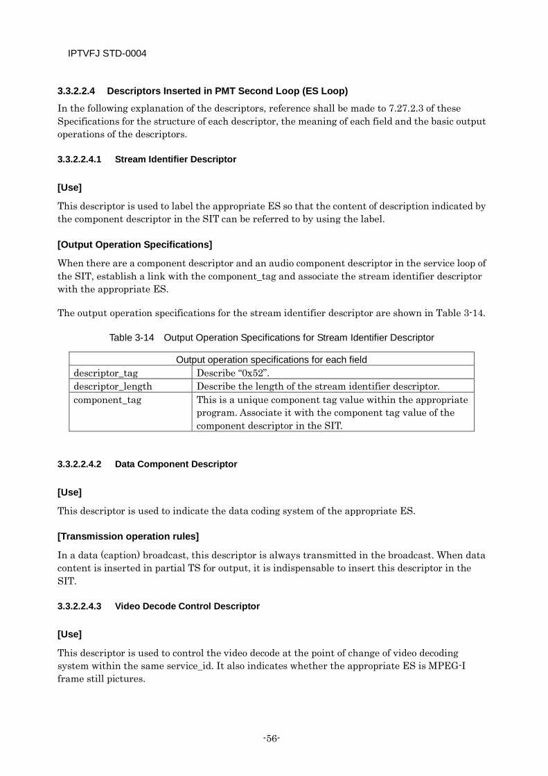
IPTVFJ STD-0004
-56-
3.3.2.2.4 Descriptors Inserted in PMT Second Loop (ES Loop)
In the following explanation of the descriptors, reference shall be made to 7.27.2.3 of these Specifications for the structure of each descriptor, the meaning of each field and the basic output operations of the descriptors.
3.3.2.2.4.1 Stream Identifier Descriptor
[Use]
This descriptor is used to label the appropriate ES so that the content of description indicated by the component descriptor in the SIT can be referred to by using the label.
[Output Operation Specifications]
When there are a component descriptor and an audio component descriptor in the service loop of the SIT, establish a link with the component_tag and associate the stream identifier descriptor with the appropriate ES.
The output operation specifications for the stream identifier descriptor are shown in Table 3-14.
Table 3-14 Output Operation Specifications for Stream Identifier Descriptor
Output operation specifications for each field descriptor_tag Describe “0x52”. descriptor_length Describe the length of the stream identifier descriptor. component_tag This is a unique component tag value within the appropriate
program. Associate it with the component tag value of the component descriptor in the SIT.
3.3.2.2.4.2 Data Component Descriptor
[Use]
This descriptor is used to indicate the data coding system of the appropriate ES.
[Transmission operation rules]
In a data (caption) broadcast, this descriptor is always transmitted in the broadcast. When data content is inserted in partial TS for output, it is indispensable to insert this descriptor in the SIT.
3.3.2.2.4.3 Video Decode Control Descriptor
[Use]
This descriptor is used to control the video decode at the point of change of video decoding system within the same service_id. It also indicates whether the appropriate ES is MPEG-I frame still pictures.
IPTVFJ STD-0004
—57—
[Output Operation Specifications]
This descriptor shall be inserted when it is described in the original broadcast and when the video making up partial TS is required to perform the operation specified by this descriptor.
[Other Special Remarks]
The video decode control descriptor contains two types of information for implementing the following reception control.
(1) Implementing seamless video switching when the video format is changed.
(2) Determining whether or not the broadcast is a still-picture broadcast based on MPEG-I frames.
When the same control as in broadcast reception is to be implemented during playback, it is recommended that the above two types of information be output. It should be noted, however, that in IP broadcasts, still-picture broadcasts are not implemented.
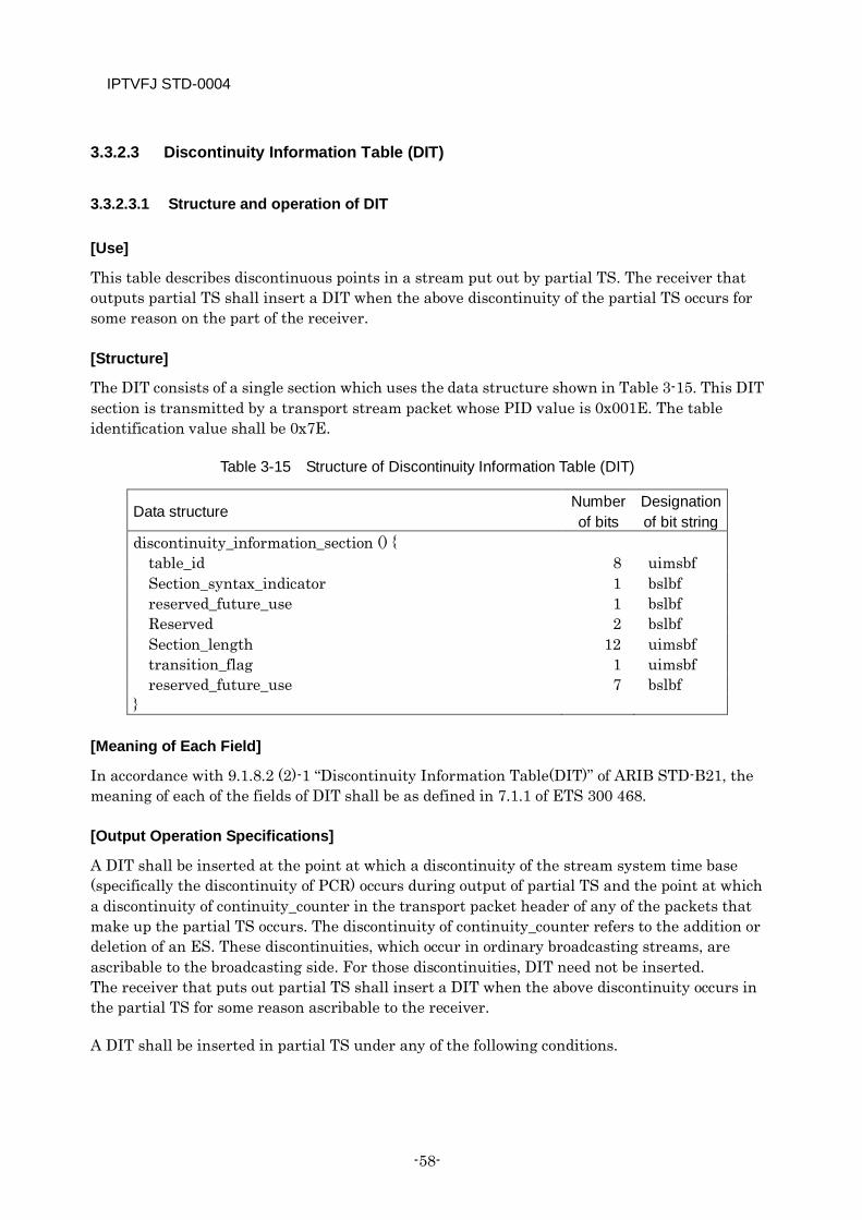
IPTVFJ STD-0004
-58-
3.3.2.3 Discontinuity Information Table (DIT)
3.3.2.3.1 Structure and operation of DIT
[Use]
This table describes discontinuous points in a stream put out by partial TS. The receiver that outputs partial TS shall insert a DIT when the above discontinuity of the partial TS occurs for some reason on the part of the receiver.
[Structure]
The DIT consists of a single section which uses the data structure shown in Table 3-15. This DIT section is transmitted by a transport stream packet whose PID value is 0x001E. The table identification value shall be 0x7E.
Table 3-15 Structure of Discontinuity Information Table (DIT)
Data structure Number of bits
Designation of bit string
discontinuity_information_section () { table_id 8 uimsbf Section_syntax_indicator 1 bslbf reserved_future_use 1 bslbf Reserved 2 bslbf Section_length 12 uimsbf transition_flag 1 uimsbf reserved_future_use 7 bslbf
}
[Meaning of Each Field]
In accordance with 9.1.8.2 (2)-1 “Discontinuity Information Table(DIT)” of ARIB STD-B21, the meaning of each of the fields of DIT shall be as defined in 7.1.1 of ETS 300 468.
[Output Operation Specifications]
A DIT shall be inserted at the point at which a discontinuity of the stream system time base (specifically the discontinuity of PCR) occurs during output of partial TS and the point at which a discontinuity of continuity_counter in the transport packet header of any of the packets that make up the partial TS occurs. The discontinuity of continuity_counter refers to the addition or deletion of an ES. These discontinuities, which occur in ordinary broadcasting streams, are ascribable to the broadcasting side. For those discontinuities, DIT need not be inserted. The receiver that puts out partial TS shall insert a DIT when the above discontinuity occurs in the partial TS for some reason ascribable to the receiver.
A DIT shall be inserted in partial TS under any of the following conditions.
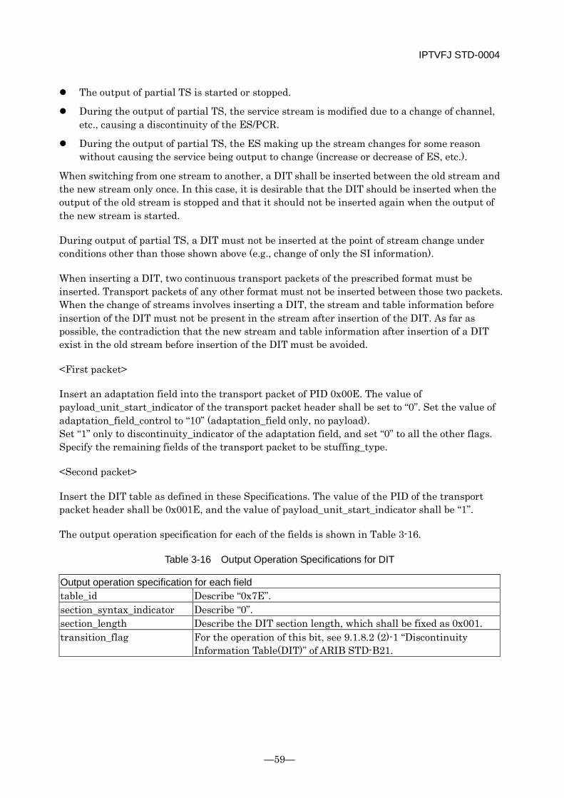
IPTVFJ STD-0004
—59—
The output of partial TS is started or stopped.
During the output of partial TS, the service stream is modified due to a change of channel, etc., causing a discontinuity of the ES/PCR.
During the output of partial TS, the ES making up the stream changes for some reason without causing the service being output to change (increase or decrease of ES, etc.).
When switching from one stream to another, a DIT shall be inserted between the old stream and the new stream only once. In this case, it is desirable that the DIT should be inserted when the output of the old stream is stopped and that it should not be inserted again when the output of the new stream is started.
During output of partial TS, a DIT must not be inserted at the point of stream change under conditions other than those shown above (e.g., change of only the SI information).
When inserting a DIT, two continuous transport packets of the prescribed format must be inserted. Transport packets of any other format must not be inserted between those two packets. When the change of streams involves inserting a DIT, the stream and table information before insertion of the DIT must not be present in the stream after insertion of the DIT. As far as possible, the contradiction that the new stream and table information after insertion of a DIT exist in the old stream before insertion of the DIT must be avoided.
<First packet>
Insert an adaptation field into the transport packet of PID 0x00E. The value of payload_unit_start_indicator of the transport packet header shall be set to “0”. Set the value of adaptation_field_control to “10” (adaptation_field only, no payload). Set “1” only to discontinuity_indicator of the adaptation field, and set “0” to all the other flags. Specify the remaining fields of the transport packet to be stuffing_type.
<Second packet>
Insert the DIT table as defined in these Specifications. The value of the PID of the transport packet header shall be 0x001E, and the value of payload_unit_start_indicator shall be “1”.
The output operation specification for each of the fields is shown in Table 3-16.
Table 3-16 Output Operation Specifications for DIT
Output operation specification for each field table_id Describe “0x7E”. section_syntax_indicator Describe “0”. section_length Describe the DIT section length, which shall be fixed as 0x001. transition_flag For the operation of this bit, see 9.1.8.2 (2)-1 “Discontinuity
Information Table(DIT)” of ARIB STD-B21.
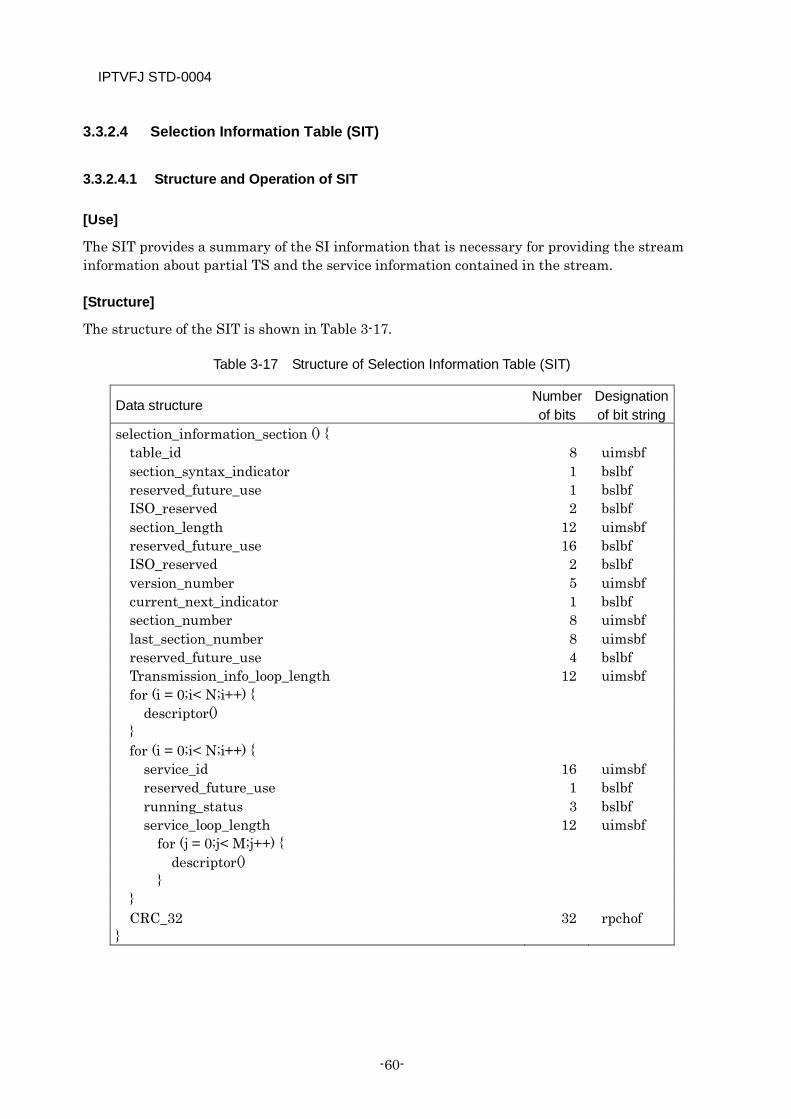
IPTVFJ STD-0004
-60-
3.3.2.4 Selection Information Table (SIT)
3.3.2.4.1 Structure and Operation of SIT
[Use]
The SIT provides a summary of the SI information that is necessary for providing the stream information about partial TS and the service information contained in the stream.
[Structure]
The structure of the SIT is shown in Table 3-17.
Table 3-17 Structure of Selection Information Table (SIT)
Data structure Number of bits
Designation of bit string
selection_information_section () { table_id 8 uimsbf section_syntax_indicator 1 bslbf reserved_future_use 1 bslbf ISO_reserved 2 bslbf section_length 12 uimsbf reserved_future_use 16 bslbf ISO_reserved 2 bslbf version_number 5 uimsbf current_next_indicator 1 bslbf section_number 8 uimsbf last_section_number 8 uimsbf reserved_future_use 4 bslbf Transmission_info_loop_length 12 uimsbf for (i = 0;i< N;i++) {
descriptor() } for (i = 0;i< N;i++) {
service_id 16 uimsbf reserved_future_use 1 bslbf running_status 3 bslbf service_loop_length 12 uimsbf
for (j = 0;j< M;j++) { descriptor()
} } CRC_32 32 rpchof
}
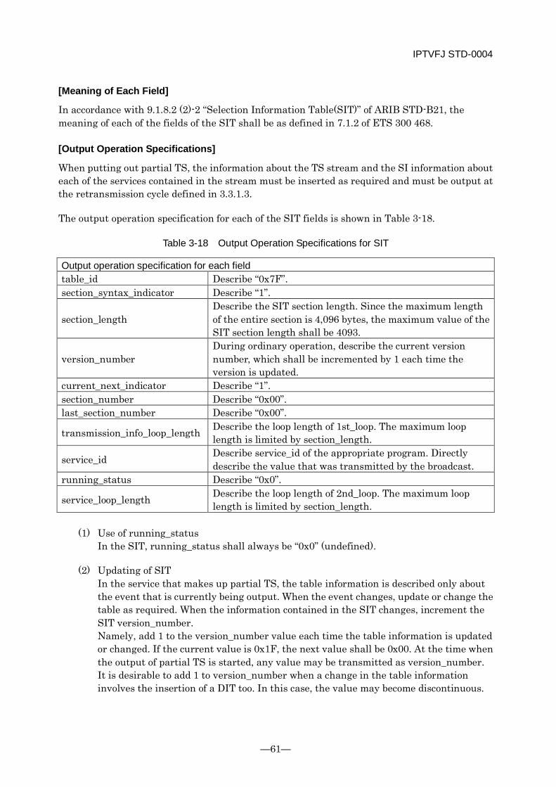
IPTVFJ STD-0004
—61—
[Meaning of Each Field]
In accordance with 9.1.8.2 (2)-2 “Selection Information Table(SIT)” of ARIB STD-B21, the meaning of each of the fields of the SIT shall be as defined in 7.1.2 of ETS 300 468.
[Output Operation Specifications]
When putting out partial TS, the information about the TS stream and the SI information about each of the services contained in the stream must be inserted as required and must be output at the retransmission cycle defined in 3.3.1.3.
The output operation specification for each of the SIT fields is shown in Table 3-18.
Table 3-18 Output Operation Specifications for SIT
Output operation specification for each field table_id Describe “0x7F”. section_syntax_indicator Describe “1”.
section_length Describe the SIT section length. Since the maximum length of the entire section is 4,096 bytes, the maximum value of the SIT section length shall be 4093.
version_number During ordinary operation, describe the current version number, which shall be incremented by 1 each time the version is updated.
current_next_indicator Describe “1”. section_number Describe “0x00”. last_section_number Describe “0x00”.
transmission_info_loop_length Describe the loop length of 1st_loop. The maximum loop length is limited by section_length.
service_id Describe service_id of the appropriate program. Directly describe the value that was transmitted by the broadcast.
running_status Describe “0x0”.
service_loop_length Describe the loop length of 2nd_loop. The maximum loop length is limited by section_length.
(1) Use of running_status
In the SIT, running_status shall always be “0x0” (undefined).
(2) Updating of SIT In the service that makes up partial TS, the table information is described only about the event that is currently being output. When the event changes, update or change the table as required. When the information contained in the SIT changes, increment the SIT version_number. Namely, add 1 to the version_number value each time the table information is updated or changed. If the current value is 0x1F, the next value shall be 0x00. At the time when the output of partial TS is started, any value may be transmitted as version_number. It is desirable to add 1 to version_number when a change in the table information involves the insertion of a DIT too. In this case, the value may become discontinuous.
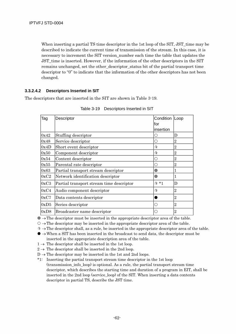
IPTVFJ STD-0004
-62-
When inserting a partial TS time descriptor in the 1st loop of the SIT, JST_time may be described to indicate the current time of transmission of the stream. In this case, it is necessary to increment the SIT version_number each time the table that updates the JST_time is inserted. However, if the information of the other descriptors in the SIT remains unchanged, set the other_descriptor_status bit of the partial transport time descriptor to “0” to indicate that the information of the other descriptors has not been changed.
3.3.2.4.2 Descriptors Inserted in SIT
The descriptors that are inserted in the SIT are shown in Table 3-19.
Table 3-19 Descriptors Inserted in SIT
Tag Descriptor Condition for insertion
Loop
0x42 Stuffing descriptor D 0x48 Service descriptor 2 0x4D Short event descriptor 2 0x50 Component descriptor 2 0x54 Content descriptor 2 0x55 Parental rate descriptor 2 0x63 Partial transport stream descriptor 1 0xC2 Network identification descriptor 1 0xC3 Partial transport stream time descriptor *1 D 0xC4 Audio component descriptor 2 0xC7 Data contents descriptor 2 0xD5 Series descriptor 2 0xD8 Broadcaster name descriptor 2
→ The descriptor must be inserted in the appropriate descriptor area of the table. → The descriptor may be inserted in the appropriate descriptor area of the table. → The descriptor shall, as a rule, be inserted in the appropriate descriptor area of the table. → When a SIT has been inserted in the broadcast to send data, the descriptor must be
inserted in the appropriate description area of the table. 1 → The descriptor shall be inserted in the 1st loop. 2 → The descriptor shall be inserted in the 2nd loop. D → The descriptor may be inserted in the 1st and 2nd loops. *1: Inserting the partial transport stream time descriptor in the 1st loop
(transmission_info_loop) is optional. As a rule, the partial transport stream time descriptor, which describes the starting time and duration of a program in EIT, shall be inserted in the 2nd loop (service_loop) of the SIT. When inserting a data contents descriptor in partial TS, describe the JST time.
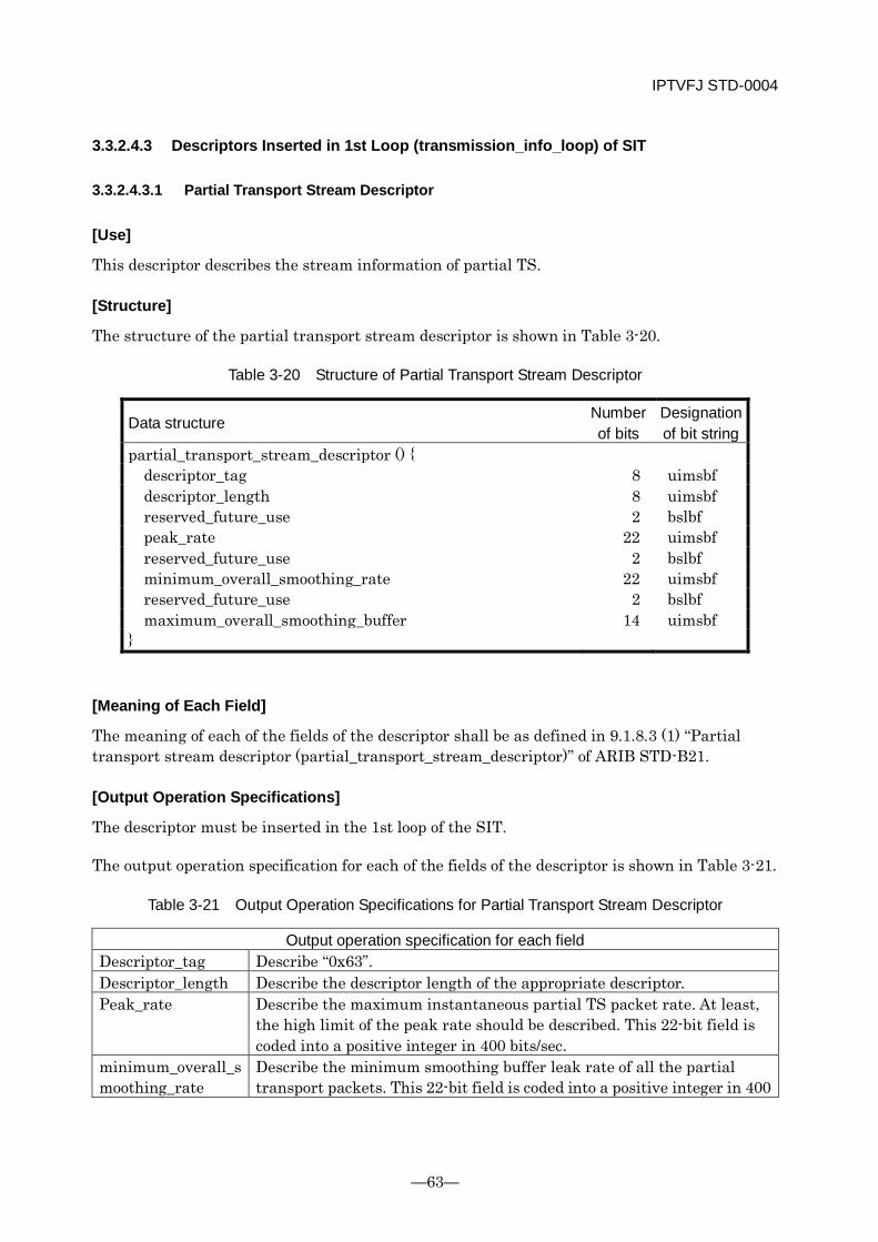
IPTVFJ STD-0004
—63—
3.3.2.4.3 Descriptors Inserted in 1st Loop (transmission_info_loop) of SIT
3.3.2.4.3.1 Partial Transport Stream Descriptor
[Use]
This descriptor describes the stream information of partial TS.
[Structure]
The structure of the partial transport stream descriptor is shown in Table 3-20.
Table 3-20 Structure of Partial Transport Stream Descriptor
Data structure Number of bits
Designation of bit string
partial_transport_stream_descriptor () { descriptor_tag 8 uimsbf descriptor_length 8 uimsbf reserved_future_use 2 bslbf peak_rate 22 uimsbf reserved_future_use 2 bslbf minimum_overall_smoothing_rate 22 uimsbf reserved_future_use 2 bslbf maximum_overall_smoothing_buffer 14 uimsbf
}
[Meaning of Each Field]
The meaning of each of the fields of the descriptor shall be as defined in 9.1.8.3 (1) “Partial transport stream descriptor (partial_transport_stream_descriptor)” of ARIB STD-B21.
[Output Operation Specifications]
The descriptor must be inserted in the 1st loop of the SIT.
The output operation specification for each of the fields of the descriptor is shown in Table 3-21.
Table 3-21 Output Operation Specifications for Partial Transport Stream Descriptor
Output operation specification for each field Descriptor_tag Describe “0x63”. Descriptor_length Describe the descriptor length of the appropriate descriptor. Peak_rate Describe the maximum instantaneous partial TS packet rate. At least,
the high limit of the peak rate should be described. This 22-bit field is coded into a positive integer in 400 bits/sec.
minimum_overall_smoothing_rate
Describe the minimum smoothing buffer leak rate of all the partial transport packets. This 22-bit field is coded into a positive integer in 400
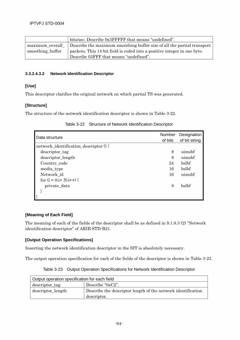
IPTVFJ STD-0004
-64-
bits/sec. Describe 0x3FFFFF that means “undefined”. maximum_overall_smoothing_buffer
Describe the maximum smoothing buffer size of all the partial transport packets. This 14-bit field is coded into a positive integer in one byte. Describe 03FFF that means “undefined”.
3.3.2.4.3.2 Network Identification Descriptor
[Use]
This descriptor clarifies the original network on which partial TS was generated.
[Structure]
The structure of the network identification descriptor is shown in Table 3-22.
Table 3-22 Structure of Network Identification Descriptor
Data structure Number of bits
Designation of bit string
network_identification_descriptor () { descriptor_tag 8 uimsbf descriptor_length 8 uimsbf Country_code 24 bslbf media_type 16 bslbf Network_id 16 uimsbf for (i = 0;i< N;i++) {
private_data 8 bslbf }
}
[Meaning of Each Field]
The meaning of each of the fields of the descriptor shall be as defined in 9.1.8.3 (2) “Network identification descriptor” of ARIB STD-B21.
[Output Operation Specifications]
Inserting the network identification descriptor in the SIT is absolutely necessary.
The output operation specification for each of the fields of the descriptor is shown in Table 3-23.
Table 3-23 Output Operation Specifications for Network Identification Descriptor
Output operation specification for each field descriptor_tag Describe “0xC2”. descriptor_length Describe the descriptor length of the network identification
descriptor.
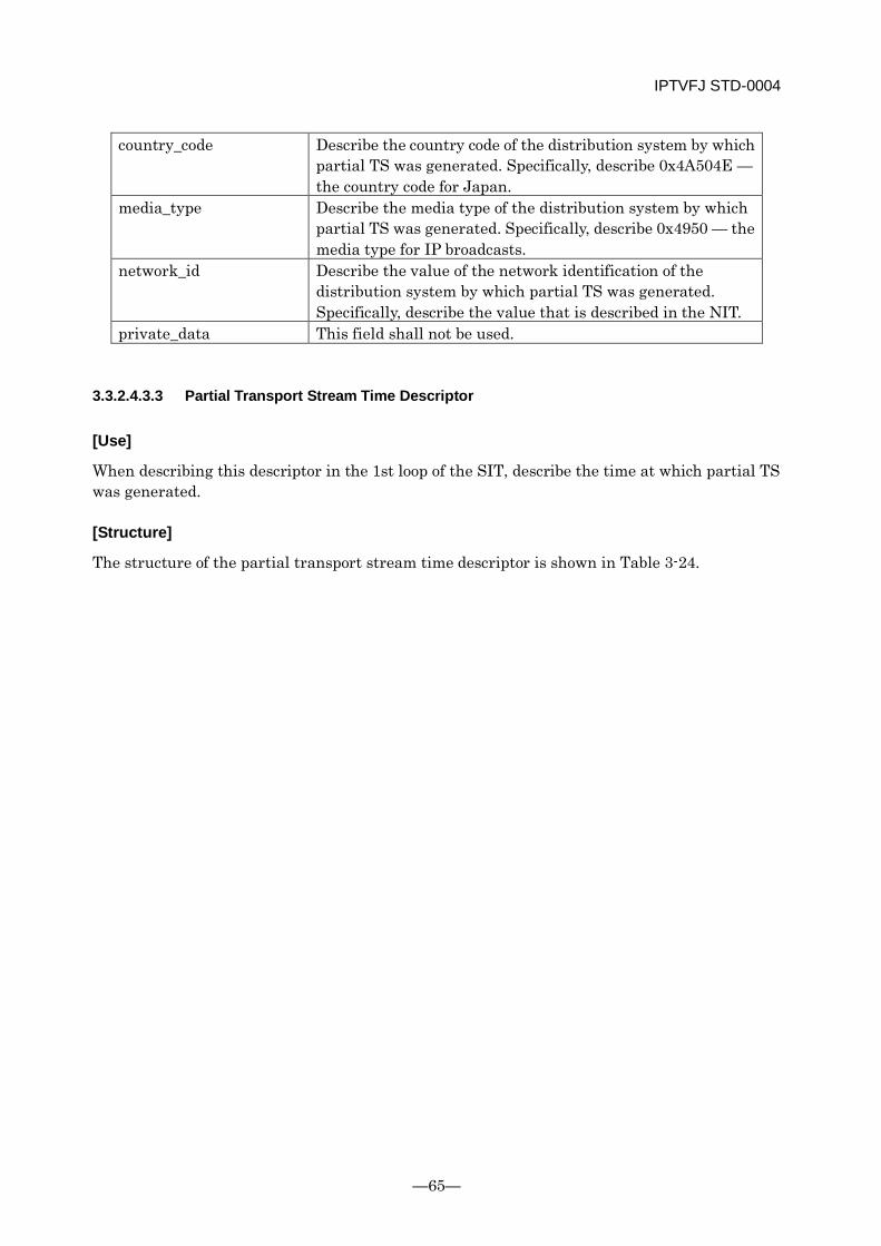
IPTVFJ STD-0004
—65—
country_code Describe the country code of the distribution system by which partial TS was generated. Specifically, describe 0x4A504E — the country code for Japan.
media_type Describe the media type of the distribution system by which partial TS was generated. Specifically, describe 0x4950 — the media type for IP broadcasts.
network_id Describe the value of the network identification of the distribution system by which partial TS was generated. Specifically, describe the value that is described in the NIT.
private_data This field shall not be used.
3.3.2.4.3.3 Partial Transport Stream Time Descriptor
[Use]
When describing this descriptor in the 1st loop of the SIT, describe the time at which partial TS was generated.
[Structure]
The structure of the partial transport stream time descriptor is shown in Table 3-24.
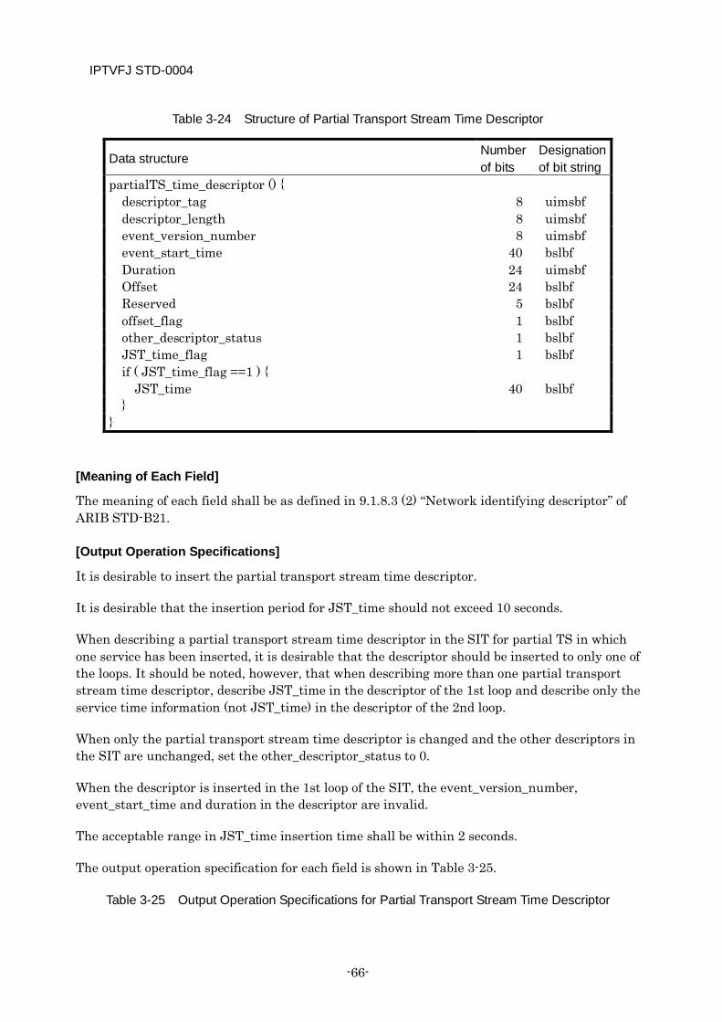
IPTVFJ STD-0004
-66-
Table 3-24 Structure of Partial Transport Stream Time Descriptor
Data structure Number of bits
Designation of bit string
partialTS_time_descriptor () { descriptor_tag 8 uimsbf descriptor_length 8 uimsbf event_version_number 8 uimsbf event_start_time 40 bslbf Duration 24 uimsbf Offset 24 bslbf Reserved 5 bslbf offset_flag 1 bslbf other_descriptor_status 1 bslbf JST_time_flag 1 bslbf if ( JST_time_flag ==1 ) {
JST_time 40 bslbf }
}
[Meaning of Each Field]
The meaning of each field shall be as defined in 9.1.8.3 (2) “Network identifying descriptor” of ARIB STD-B21.
[Output Operation Specifications]
It is desirable to insert the partial transport stream time descriptor.
It is desirable that the insertion period for JST_time should not exceed 10 seconds.
When describing a partial transport stream time descriptor in the SIT for partial TS in which one service has been inserted, it is desirable that the descriptor should be inserted to only one of the loops. It should be noted, however, that when describing more than one partial transport stream time descriptor, describe JST_time in the descriptor of the 1st loop and describe only the service time information (not JST_time) in the descriptor of the 2nd loop.
When only the partial transport stream time descriptor is changed and the other descriptors in the SIT are unchanged, set the other_descriptor_status to 0.
When the descriptor is inserted in the 1st loop of the SIT, the event_version_number, event_start_time and duration in the descriptor are invalid.
The acceptable range in JST_time insertion time shall be within 2 seconds.
The output operation specification for each field is shown in Table 3-25.
Table 3-25 Output Operation Specifications for Partial Transport Stream Time Descriptor
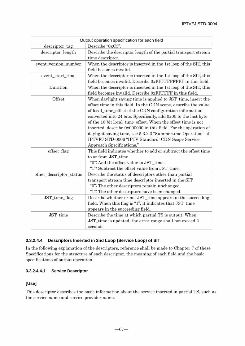
IPTVFJ STD-0004
—67—
Output operation specification for each field descriptor_tag Describe “0xC3”.
descriptor_length Describe the descriptor length of the partial transport stream time descriptor.
event_version_number When the descriptor is inserted in the 1st loop of the SIT, this field becomes invalid.
event_start_time When the descriptor is inserted in the 1st loop of the SIT, this field becomes invalid. Describe 0xFFFFFFFFFF in this field.
Duration When the descriptor is inserted in the 1st loop of the SIT, this field becomes invalid. Describe 0xFFFFFF in this field.
Offset When daylight saving time is applied to JST_time, insert the offset time in this field. In the CDN scope, describe the value of local_time_offset of the CDN configuration information converted into 24 bits. Specifically, add 0x00 to the last byte of the 16-bit local_time_offset. When the offset time is not inserted, describe 0x000000 in this field. For the operation of daylight saving time, see 5.3.2.3 “Summertime Operation” of IPTVFJ STD-0006 “IPTV Standard: CDN Scope Service Approach Specifications.”
offset_flag This field indicates whether to add or subtract the offset time to or from JST_time. “0”: Add the offset value to JST_time. “1”: Subtract the offset value from JST_time.
other_descriptor_status Describe the status of descriptors other than partial transport stream time descriptor inserted in the SIT. “0”: The other descriptors remain unchanged. “1”: The other descriptors have been changed.
JST_time_flag Describe whether or not JST_time appears in the succeeding field. When this flag is “1”, it indicates that JST_time appears in the succeeding field.
JST_time Describe the time at which partial TS is output. When JST_time is updated, the error range shall not exceed 2 seconds.
3.3.2.4.4 Descriptors Inserted in 2nd Loop (Service Loop) of SIT
In the following explanation of the descriptors, reference shall be made to Chapter 7 of these Specifications for the structure of each descriptor, the meaning of each field and the basic specifications of output operation.
3.3.2.4.4.1 Service Descriptor
[Use]
This descriptor describes the basic information about the service inserted in partial TS, such as the service name and service provider name.
IPTVFJ STD-0004
-68-
[Output Operation Specifications]
Only one service descriptor shall be inserted for the appropriate service.
The service provider name and service name shall be those which are obtained from the broadcast.
3.3.2.4.4.2 Short Event Descriptor
[Use]
This descriptor describes the event name and short character information about the event.
[Output Operation Specifications]
As a rule, this descriptor shall be inserted in the SIT.
Only one short event descriptor shall be output for one event.
Output the short event descriptor that has been obtained from the broadcast.
3.3.2.4.4.3 Component Descriptor
[Use]
This descriptor describes the information about the video component stream making up an event.
[Output Operation Specifications]
In a broadcast, one component descriptor is always output for each of the video components that are included in an event. Therefore, when a stream identification descriptor has been inserted in the PMT, the component descriptor that is associated with the video component inserted in the SIT and that has been transmitted by the broadcast shall, as a rule, be inserted in the SIT.
[Other Special Remarks]
In a broadcast the description of a component may not correspond with the actual component due to a change of mode in the event, etc. In this case, although it is desirable that arrangements should be made to prevent any contradiction in the configuration of partial TS, the value of the descriptor that has been transmitted by the broadcast may directly be set in the SIT. (In a broadcast, component_type of the component descriptor describes the representative component type of the broadcast program and the value thereof is not changed on a real-time basis even if the mode is changed while the program is broadcast. This should be kept in mind when putting out partial TS.)
3.3.2.4.4.4 Parental Rate Descriptor
[Use]
This descriptor describes a parental rate for an event.
IPTVFJ STD-0004
—69—
[Output Operation Specifications]
This descriptor may be inserted only in an event in which the same descriptor has been inserted in a broadcast.
3.3.2.4.4.5 Audio Component Descriptor
[Use]
This descriptor describes the information about the audio component stream that constitutes an event.
[Output Operation Specifications]
In a broadcast, one audio component descriptor is always output for each of the audio components that are included in an event. Therefore, when a stream identification descriptor has been inserted in the PMT, the descriptor that is associated with the audio component inserted in the SIT and that has been transmitted by the broadcast shall, as a rule, be directly inserted in the SIT.
[Other Special Remarks]
In a broadcast, the description of a component may not correspond with the actual component due to a change of mode, etc. in the broadcast event. In this case, although it is desirable that arrangements should be made to prevent any contradiction in the configuration of partial TS, the value of the audio component descriptor that has been transmitted by the broadcast may directly be set in the SIT. (The component_type of this descriptor describes the representative component type of the program and the value thereof is not changed on a real-time basis even if the mode is changed during the program. This should be kept in mind when exporting partial TS.)
3.3.2.4.4.6 Data Content Descriptor
[Use]
This descriptor describes the information about the data component stream that constitutes an event.
[Output Operation Specifications]
In a broadcast, a data content descriptor may be optionally transmitted for a data component (caption) included in an event. When data containing a data content descriptor is inserted in partial TS, it is necessary to insert the descriptor in the SIT.
3.3.2.4.4.7 Content Descriptor
[Use]
This descriptor describes the information about the genre of an event.
IPTVFJ STD-0004
-70-
[Output Operation Specifications]
Inserting this descriptor in the SIT is optional.
When this descriptor is inserted in the SIT, a single content descriptor for each program may be optionally transmitted in the broadcast. When this descriptor is transmitted, the value thereof shall be directly inserted in the SIT.
3.3.2.4.4.8 Series Descriptor
[Use]
This descriptor is used to identify a series program.
[Output Operation Specifications]
When inserting this descriptor in the SIT, directly describe the one that has been transmitted by the broadcast.
3.3.2.4.4.9 Broadcaster Name Descriptor
[Use]
This descriptor is used to indicate an IP broadcaster name.
[Output Operation Specifications]
When inserting this descriptor in the SIT, directly describe the one that has been transmitted by the broadcast.
3.3.2.4.4.10 Partial Transport Stream Time Descriptor
[Use]
When this descriptor is inserted in the 2nd loop of the SIT, it describes the time information about the event inserted in the SIT.
[Structure]
For the structure of the partial transport stream time descriptor, see Table 3-24.
[Meaning of Each Field]
The meaning of each field shall be as defined in 9.1.8.3 (2) “Network identification descriptor” of ARIB STD-B21.
[Output Operation Specifications]
This descriptor shall, as a rule, be inserted in the SIT.
When inserting JST_time, it is desirable that the period of insertion should not exceed 10 seconds.
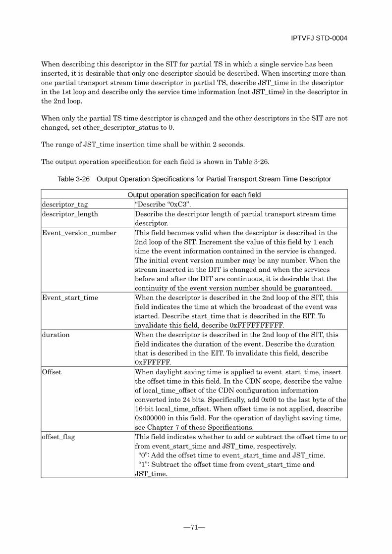
IPTVFJ STD-0004
—71—
When describing this descriptor in the SIT for partial TS in which a single service has been inserted, it is desirable that only one descriptor should be described. When inserting more than one partial transport stream time descriptor in partial TS, describe JST_time in the descriptor in the 1st loop and describe only the service time information (not JST_time) in the descriptor in the 2nd loop.
When only the partial TS time descriptor is changed and the other descriptors in the SIT are not changed, set other_descriptor_status to 0.
The range of JST_time insertion time shall be within 2 seconds.
The output operation specification for each field is shown in Table 3-26.
Table 3-26 Output Operation Specifications for Partial Transport Stream Time Descriptor
Output operation specification for each field descriptor_tag “Describe “0xC3”. descriptor_length Describe the descriptor length of partial transport stream time
descriptor. Event_version_number This field becomes valid when the descriptor is described in the
2nd loop of the SIT. Increment the value of this field by 1 each time the event information contained in the service is changed. The initial event version number may be any number. When the stream inserted in the DIT is changed and when the services before and after the DIT are continuous, it is desirable that the continuity of the event version number should be guaranteed.
Event_start_time When the descriptor is described in the 2nd loop of the SIT, this field indicates the time at which the broadcast of the event was started. Describe start_time that is described in the EIT. To invalidate this field, describe 0xFFFFFFFFFF.
duration When the descriptor is described in the 2nd loop of the SIT, this field indicates the duration of the event. Describe the duration that is described in the EIT. To invalidate this field, describe 0xFFFFFF.
Offset When daylight saving time is applied to event_start_time, insert the offset time in this field. In the CDN scope, describe the value of local_time_offset of the CDN configuration information converted into 24 bits. Specifically, add 0x00 to the last byte of the 16-bit local_time_offset. When offset time is not applied, describe 0x000000 in this field. For the operation of daylight saving time, see Chapter 7 of these Specifications.
offset_flag This field indicates whether to add or subtract the offset time to or from event_start_time and JST_time, respectively. “0”: Add the offset time to event_start_time and JST_time. “1”: Subtract the offset time from event_start_time and JST_time.
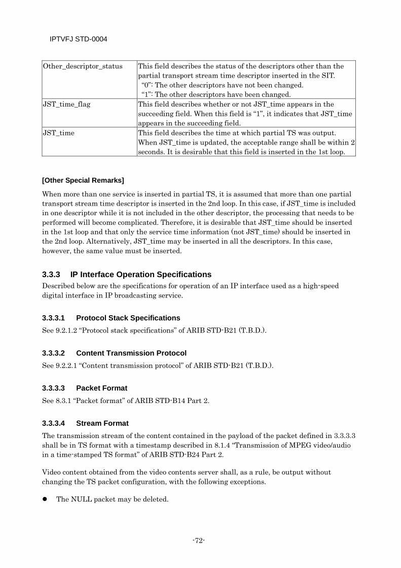
IPTVFJ STD-0004
-72-
Other_descriptor_status This field describes the status of the descriptors other than the partial transport stream time descriptor inserted in the SIT. “0”: The other descriptors have not been changed. “1”: The other descriptors have been changed.
JST_time_flag This field describes whether or not JST_time appears in the succeeding field. When this field is “1”, it indicates that JST_time appears in the succeeding field.
JST_time This field describes the time at which partial TS was output. When JST_time is updated, the acceptable range shall be within 2 seconds. It is desirable that this field is inserted in the 1st loop.
[Other Special Remarks]
When more than one service is inserted in partial TS, it is assumed that more than one partial transport stream time descriptor is inserted in the 2nd loop. In this case, if JST_time is included in one descriptor while it is not included in the other descriptor, the processing that needs to be performed will become complicated. Therefore, it is desirable that JST_time should be inserted in the 1st loop and that only the service time information (not JST_time) should be inserted in the 2nd loop. Alternatively, JST_time may be inserted in all the descriptors. In this case, however, the same value must be inserted.
3.3.3 IP Interface Operation Specifications Described below are the specifications for operation of an IP interface used as a high-speed digital interface in IP broadcasting service.
3.3.3.1 Protocol Stack Specifications See 9.2.1.2 “Protocol stack specifications” of ARIB STD-B21 (T.B.D.).
3.3.3.2 Content Transmission Protocol See 9.2.2.1 “Content transmission protocol” of ARIB STD-B21 (T.B.D.).
3.3.3.3 Packet Format See 8.3.1 “Packet format” of ARIB STD-B14 Part 2.
3.3.3.4 Stream Format The transmission stream of the content contained in the payload of the packet defined in 3.3.3.3 shall be in TS format with a timestamp described in 8.1.4 “Transmission of MPEG video/audio in a time-stamped TS format” of ARIB STD-B24 Part 2.
Video content obtained from the video contents server shall, as a rule, be output without changing the TS packet configuration, with the following exceptions.
The NULL packet may be deleted.
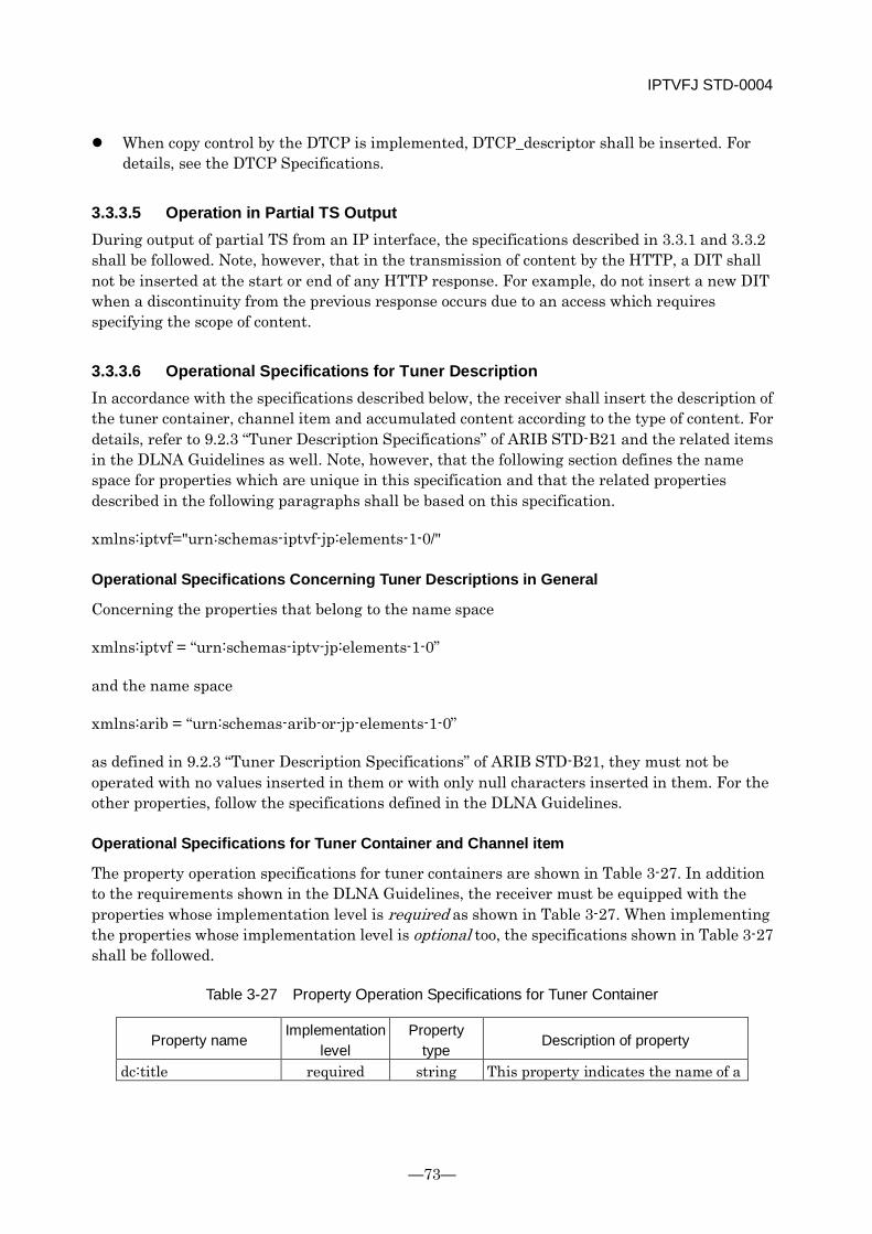
IPTVFJ STD-0004
—73—
When copy control by the DTCP is implemented, DTCP_descriptor shall be inserted. For details, see the DTCP Specifications.
3.3.3.5 Operation in Partial TS Output During output of partial TS from an IP interface, the specifications described in 3.3.1 and 3.3.2 shall be followed. Note, however, that in the transmission of content by the HTTP, a DIT shall not be inserted at the start or end of any HTTP response. For example, do not insert a new DIT when a discontinuity from the previous response occurs due to an access which requires specifying the scope of content.
3.3.3.6 Operational Specifications for Tuner Description In accordance with the specifications described below, the receiver shall insert the description of the tuner container, channel item and accumulated content according to the type of content. For details, refer to 9.2.3 “Tuner Description Specifications” of ARIB STD-B21 and the related items in the DLNA Guidelines as well. Note, however, that the following section defines the name space for properties which are unique in this specification and that the related properties described in the following paragraphs shall be based on this specification.
xmlns:iptvf="urn:schemas-iptvf-jp:elements-1-0/"
Operational Specifications Concerning Tuner Descriptions in General
Concerning the properties that belong to the name space
xmlns:iptvf = “urn:schemas-iptv-jp:elements-1-0”
and the name space
xmlns:arib = “urn:schemas-arib-or-jp-elements-1-0”
as defined in 9.2.3 “Tuner Description Specifications” of ARIB STD-B21, they must not be operated with no values inserted in them or with only null characters inserted in them. For the other properties, follow the specifications defined in the DLNA Guidelines.
Operational Specifications for Tuner Container and Channel item
The property operation specifications for tuner containers are shown in Table 3-27. In addition to the requirements shown in the DLNA Guidelines, the receiver must be equipped with the properties whose implementation level is required as shown in Table 3-27. When implementing the properties whose implementation level is optional too, the specifications shown in Table 3-27 shall be followed.
Table 3-27 Property Operation Specifications for Tuner Container
Property name Implementation
level Property
type Description of property
dc:title required string This property indicates the name of a
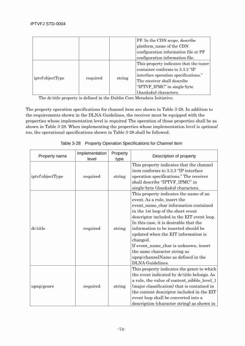
IPTVFJ STD-0004
-74-
PF. In the CDN scope, describe platform_name of the CDN configuration information file or PF configuration information file.
iptvf:objectType required string
This property indicates that the tuner container conforms to 3.3.3 “IP interface operation specifications.” The receiver shall describe “IPTVF_IPMC” in single-byte (hankaku) characters.
The dc:title property is defined in the Dublin Core Metadata Initiative. The property operation specifications for channel item are shown in Table 3-28. In addition to the requirements shown in the DLNA Guidelines, the receiver must be equipped with the properties whose implementation level is required. The operation of those properties shall be as shown in Table 3-28. When implementing the properties whose implementation level is optional too, the operational specifications shown in Table 3-28 shall be followed.
Table 3-28 Property Operation Specifications for Channel Item
Property name Implementation level
Property type Description of property
iptvf:objectType required string
This property indicates that the channel item conforms to 3.3.3 “IP interface operation specifications.” The receiver shall describe “IPTVF_IPMC” in single-byte (hankaku) characters.
dc:title required string
This property indicates the name of an event. As a rule, insert the event_name_char information contained in the 1st loop of the short event descriptor included in the EIT event loop. In this case, it is desirable that the information to be inserted should be updated when the EIT information is changed. If event_name_char is unknown, insert the same character string as upnp:channelName as defined in the DLNA Guidelines.
upnp:genre required string
This property indicates the genre to which the event indicated by dc:title belongs. As a rule, the value of content_nibble_level_1 (major classification) that is contained in the content descriptor included in the EIT event loop shall be converted into a description (character string) as shown in
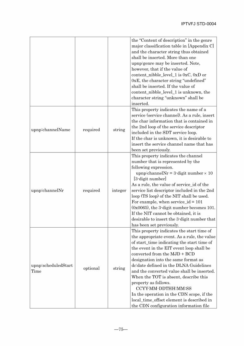
IPTVFJ STD-0004
—75—
the “Content of description” in the genre major classification table in [Appendix C] and the character string thus obtained shall be inserted. More than one upnp:genre may be inserted. Note, however, that if the value of content_nibble_level_1 is 0xC, 0xD or 0xE, the character string “undefined” shall be inserted. If the value of content_nibble_level_1 is unknown, the character string “unknown” shall be inserted.
upnp:channelName required string
This property indicates the name of a service (service channel). As a rule, insert the char information that is contained in the 2nd loop of the service descriptor included in the SDT service loop. If the char is unknown, it is desirable to insert the service channel name that has been set previously.
upnp:channelNr required integer
This property indicates the channel number that is represented by the following expression.
upnp:channelNr = 3-digit number × 10 [3-digit number] As a rule, the value of service_id of the service list descriptor included in the 2nd loop (TS loop) of the NIT shall be used. For example, when service_id = 101 (0x0065), the 3-digit number becomes 101. If the NIT cannot be obtained, it is desirable to insert the 3-digit number that has been set previously.
upnp:scheduledStartTime optional string
This property indicates the start time of the appropriate event. As a rule, the value of start_time indicating the start time of the event in the EIT event loop shall be converted from the MJD + BCD designation into the same format as dc:date defined in the DLNA Guidelines and the converted value shall be inserted. When the TOT is absent, describe this property as follows.
CCYY-MM-DDTHH:MM:SS In the operation in the CDN scope, if the local_time_offset element is described in the CDN configuration information file
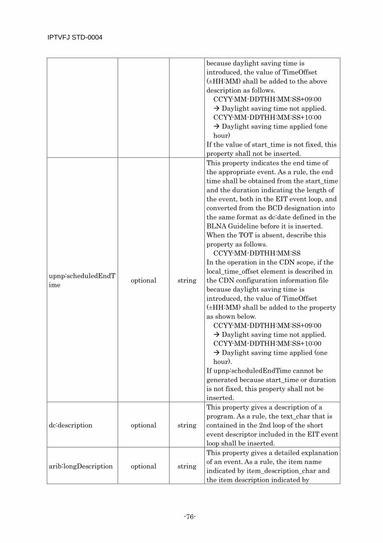
IPTVFJ STD-0004
-76-
because daylight saving time is introduced, the value of TimeOffset (±HH:MM) shall be added to the above description as follows.
CCYY-MM-DDTHH:MM:SS+09:00 Daylight saving time not applied. CCYY-MM-DDTHH:MM:SS+10:00 Daylight saving time applied (one hour)
If the value of start_time is not fixed, this property shall not be inserted.
upnp:scheduledEndTime optional string
This property indicates the end time of the appropriate event. As a rule, the end time shall be obtained from the start_time and the duration indicating the length of the event, both in the EIT event loop, and converted from the BCD designation into the same format as dc:date defined in the BLNA Guideline before it is inserted. When the TOT is absent, describe this property as follows.
CCYY-MM-DDTHH:MM:SS In the operation in the CDN scope, if the local_time_offset element is described in the CDN configuration information file because daylight saving time is introduced, the value of TimeOffset (±HH:MM) shall be added to the property as shown below.
CCYY-MM-DDTHH:MM:SS+09:00 Daylight saving time not applied. CCYY-MM-DDTHH:MM:SS+10:00 Daylight saving time applied (one hour).
If upnp:scheduledEndTime cannot be generated because start_time or duration is not fixed, this property shall not be inserted.
dc:description optional string
This property gives a description of a program. As a rule, the text_char that is contained in the 2nd loop of the short event descriptor included in the EIT event loop shall be inserted.
arib:longDescription optional string
This property gives a detailed explanation of an event. As a rule, the item name indicated by item_description_char and the item description indicated by
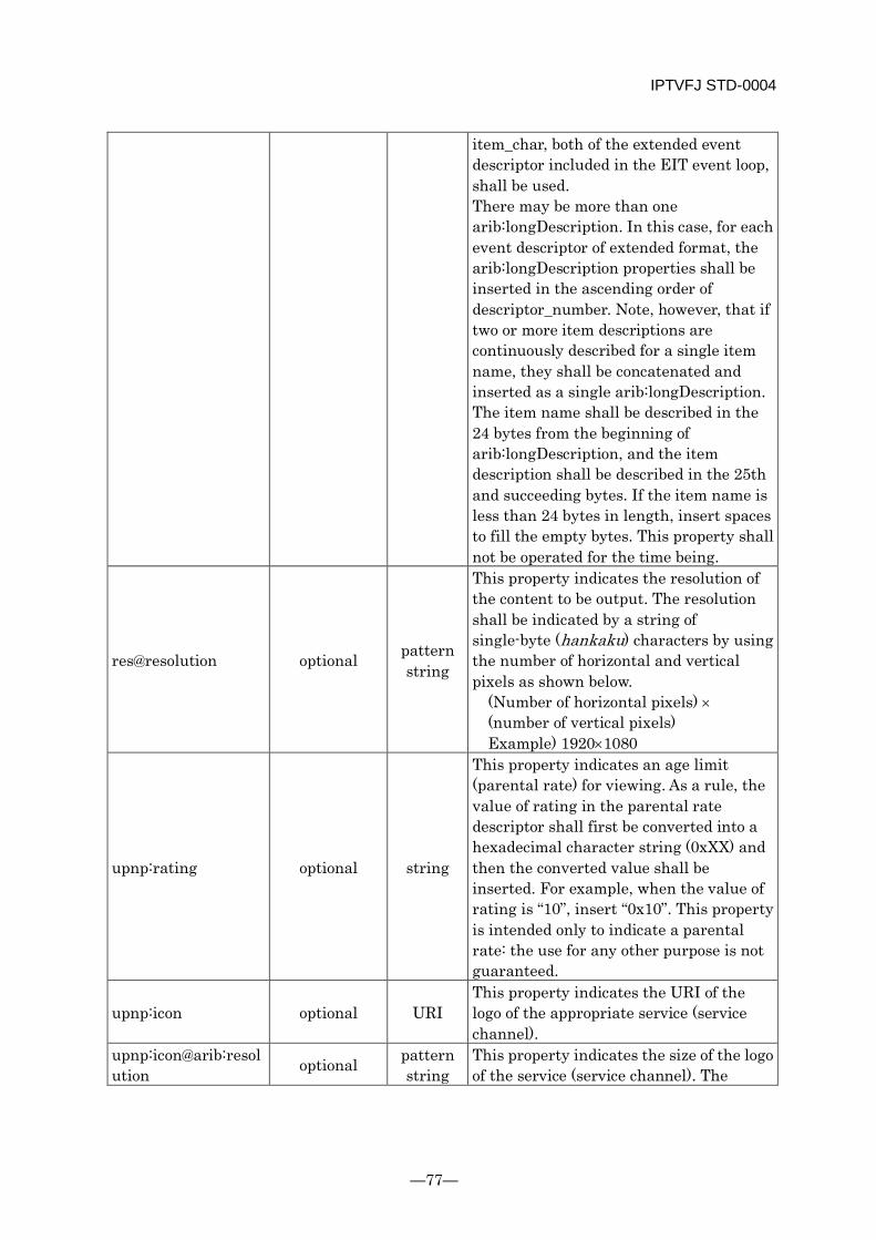
IPTVFJ STD-0004
—77—
item_char, both of the extended event descriptor included in the EIT event loop, shall be used. There may be more than one arib:longDescription. In this case, for each event descriptor of extended format, the arib:longDescription properties shall be inserted in the ascending order of descriptor_number. Note, however, that if two or more item descriptions are continuously described for a single item name, they shall be concatenated and inserted as a single arib:longDescription. The item name shall be described in the 24 bytes from the beginning of arib:longDescription, and the item description shall be described in the 25th and succeeding bytes. If the item name is less than 24 bytes in length, insert spaces to fill the empty bytes. This property shall not be operated for the time being.
res@resolution optional pattern string
This property indicates the resolution of the content to be output. The resolution shall be indicated by a string of single-byte (hankaku) characters by using the number of horizontal and vertical pixels as shown below.
(Number of horizontal pixels) × (number of vertical pixels) Example) 1920×1080
upnp:rating optional string
This property indicates an age limit (parental rate) for viewing. As a rule, the value of rating in the parental rate descriptor shall first be converted into a hexadecimal character string (0xXX) and then the converted value shall be inserted. For example, when the value of rating is “10”, insert “0x10”. This property is intended only to indicate a parental rate: the use for any other purpose is not guaranteed.
upnp:icon optional URI This property indicates the URI of the logo of the appropriate service (service channel).
upnp:icon@arib:resolution optional pattern
string This property indicates the size of the logo of the service (service channel). The
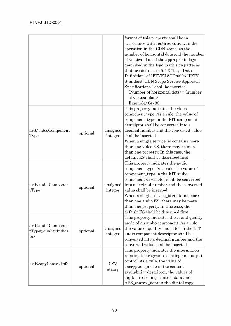
IPTVFJ STD-0004
-78-
format of this property shall be in accordance with res@resolution. In the operation in the CDN scope, as the number of horizontal dots and the number of vertical dots of the appropriate logo described in the logo mark size patterns that are defined in 5.4.3 “Logo Data Definition” of IPTVFJ STD-0006 “IPTV Standard: CDN Scope Service Approach Specifications.” shall be inserted.
(Number of horizontal dots) × (number of vertical dots) Example) 64×36
arib:videoComponentType optional unsigned
integer
This property indicates the video component type. As a rule, the value of component_type in the EIT component descriptor shall be converted into a decimal number and the converted value shall be inserted. When a single service_id contains more than one video ES, there may be more than one property. In this case, the default ES shall be described first.
arib:audioComponentType optional unsigned
integer
This property indicates the audio component type. As a rule, the value of component_type in the EIT audio component descriptor shall be converted into a decimal number and the converted value shall be inserted. When a single service_id contains more than one audio ES, there may be more than one property. In this case, the default ES shall be described first.
arib:audioComponentType@qualityIndicator
optional unsigned integer
This property indicates the sound quality mode of an audio component. As a rule, the value of quality_indicator in the EIT audio component descriptor shall be converted into a decimal number and the converted value shall be inserted.
arib:copyControlInfo optional CSV
string
This property indicates the information relating to program recording and output control. As a rule, the value of encryption_mode in the content availability descriptor, the values of digital_recording_control_data and APS_control_data in the digital copy
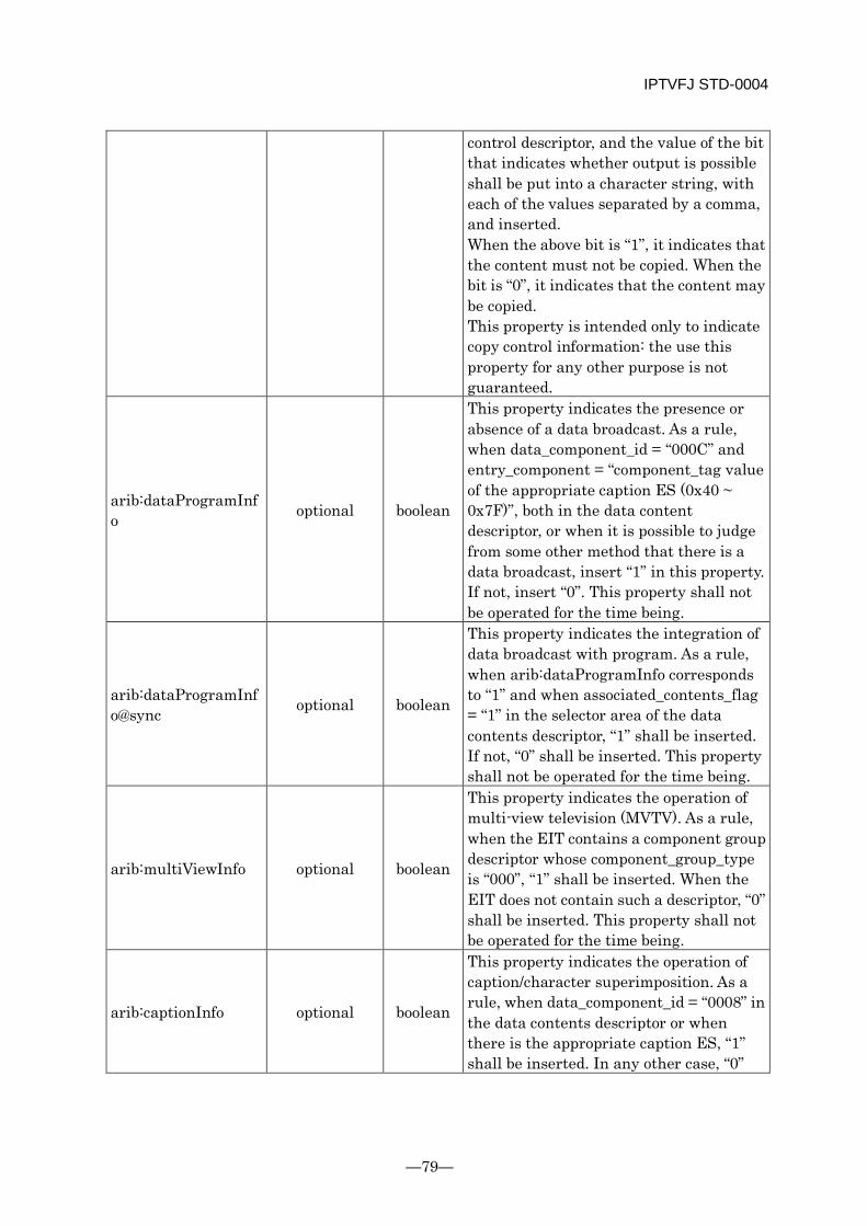
IPTVFJ STD-0004
—79—
control descriptor, and the value of the bit that indicates whether output is possible shall be put into a character string, with each of the values separated by a comma, and inserted. When the above bit is “1”, it indicates that the content must not be copied. When the bit is “0”, it indicates that the content may be copied. This property is intended only to indicate copy control information: the use this property for any other purpose is not guaranteed.
arib:dataProgramInfo optional boolean
This property indicates the presence or absence of a data broadcast. As a rule, when data_component_id = “000C” and entry_component = “component_tag value of the appropriate caption ES (0x40 ~ 0x7F)”, both in the data content descriptor, or when it is possible to judge from some other method that there is a data broadcast, insert “1” in this property. If not, insert “0”. This property shall not be operated for the time being.
arib:dataProgramInfo@sync optional boolean
This property indicates the integration of data broadcast with program. As a rule, when arib:dataProgramInfo corresponds to “1” and when associated_contents_flag = “1” in the selector area of the data contents descriptor, “1” shall be inserted. If not, “0” shall be inserted. This property shall not be operated for the time being.
arib:multiViewInfo optional boolean
This property indicates the operation of multi-view television (MVTV). As a rule, when the EIT contains a component group descriptor whose component_group_type is “000”, “1” shall be inserted. When the EIT does not contain such a descriptor, “0” shall be inserted. This property shall not be operated for the time being.
arib:captionInfo optional boolean
This property indicates the operation of caption/character superimposition. As a rule, when data_component_id = “0008” in the data contents descriptor or when there is the appropriate caption ES, “1” shall be inserted. In any other case, “0”
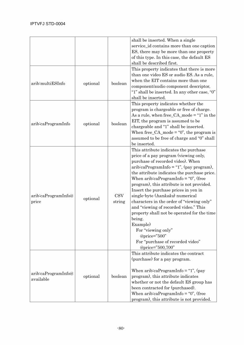
IPTVFJ STD-0004
-80-
shall be inserted. When a single service_id contains more than one caption ES, there may be more than one property of this type. In this case, the default ES shall be described first.
arib:multiESInfo optional boolean
This property indicates that there is more than one video ES or audio ES. As a rule, when the EIT contains more than one component/audio component descriptor, “1” shall be inserted. In any other case, “0” shall be inserted.
arib:caProgramInfo optional boolean
This property indicates whether the program is chargeable or free of charge. As a rule, when free_CA_mode = “1” in the EIT, the program is assumed to be chargeable and “1” shall be inserted. When free_CA_mode = “0”, the program is assumed to be free of charge and “0” shall be inserted.
arib:caProgramInfo@price optional CSV
string
This attribute indicates the purchase price of a pay program (viewing only, purchase of recorded video). When arib:caProgramInfo = “1”, (pay program), the attribute indicates the purchase price. When arib:caProgramInfo = “0”, (free program), this attribute is not provided. Insert the purchase prices in yen in single-byte (hankaku) numerical characters in the order of “viewing only” and “viewing of recorded video.” This property shall not be operated for the time being. Example) For “viewing only” @price=”500” For “purchase of recorded video” @price=”500,700”
arib:caProgramInfo@available optional boolean
This attribute indicates the contract (purchase) for a pay program. When arib:caProgramInfo = “1”, (pay program), this attribute indicates whether or not the default ES group has been contracted for (purchased). When arib:caProgramInfo = “0”, (free program), this attribute is not provided.
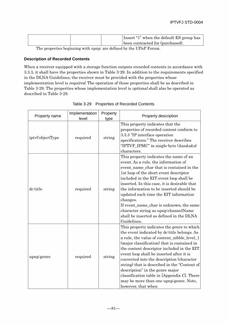
IPTVFJ STD-0004
—81—
Insert “1” when the default ES group has been contracted for (purchased).
The properties beginning with upnp: are defined by the UPnP Forum.
Description of Recorded Contents
When a receiver equipped with a storage function outputs recorded contents in accordance with 3.3.3, it shall have the properties shown in Table 3-29. In addition to the requirements specified in the DLNA Guidelines, the receiver must be provided with the properties whose implementation level is required. The operation of those properties shall be as described in Table 3-29. The properties whose implementation level is optional shall also be operated as described in Table 3-29.
Table 3-29 Properties of Recorded Contents
Property name Implementation level
Property type Property description
iptvf:objectType required string
This property indicates that the properties of recorded content conform to 3.3.3 “IP interface operation specifications.” The receiver describes “IPTVF_IPMC” in single-byte (hankaku) characters.
dc:title required string
This property indicates the name of an event. As a rule, the information of event_name_char that is contained in the 1st loop of the short event descriptor included in the EIT event loop shall be inserted. In this case, it is desirable that the information to be inserted should be updated each time the EIT information changes. If event_name_char is unknown, the same character string as upnp:channelName shall be inserted as defined in the DLNA Guidelines.
upnp:genre required string
This property indicates the genre to which the event indicated by dc:title belongs. As a rule, the value of content_nibble_level_1 (major classification) that is contained in the content descriptor included in the EIT event loop shall be inserted after it is converted into the description (character string) that is described in the “Content of description” in the genre major classification table in [Appendix C]. There may be more than one upnp:genre. Note, however, that when
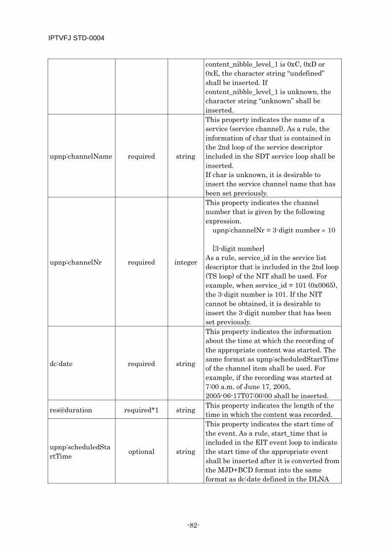
IPTVFJ STD-0004
-82-
content_nibble_level_1 is 0xC, 0xD or 0xE, the character string “undefined” shall be inserted. If content_nibble_level_1 is unknown, the character string “unknown” shall be inserted.
upnp:channelName required string
This property indicates the name of a service (service channel). As a rule, the information of char that is contained in the 2nd loop of the service descriptor included in the SDT service loop shall be inserted. If char is unknown, it is desirable to insert the service channel name that has been set previously.
upnp:channelNr required integer
This property indicates the channel number that is given by the following expression.
upnp:channelNr = 3-digit number × 10 [3-digit number]
As a rule, service_id in the service list descriptor that is included in the 2nd loop (TS loop) of the NIT shall be used. For example, when service_id = 101 (0x0065), the 3-digit number is 101. If the NIT cannot be obtained, it is desirable to insert the 3-digit number that has been set previously.
dc:date required string
This property indicates the information about the time at which the recording of the appropriate content was started. The same format as upnp:scheduledStartTime of the channel item shall be used. For example, if the recording was started at 7:00 a.m. of June 17, 2005, 2005-06-17T07:00:00 shall be inserted.
res@duration required*1 string This property indicates the length of the time in which the content was recorded.
upnp:scheduledStartTime optional string
This property indicates the start time of the event. As a rule, start_time that is included in the EIT event loop to indicate the start time of the appropriate event shall be inserted after it is converted from the MJD+BCD format into the same format as dc:date defined in the DLNA
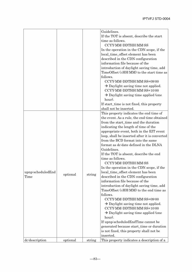
IPTVFJ STD-0004
—83—
Guidelines. If the TOT is absent, describe the start time as follows.
CCYY-MM-DDTHH:MM:SS In the operation in the CDN scope, if the local_time_offset element has been described in the CDN configuration information file because of the introduction of daylight saving time, add TimeOffset (±HH:MM) to the start time as follows.
CCYY-MM-DDTHH:MM:SS+09:00 Daylight saving time not applied. CCYY-MM-DDTHH:MM:SS+10:00 Daylight saving time applied (one hour).
If start_time is not fixed, this property shall not be inserted.
upnp:scheduledEndTime optional string
This property indicates the end time of the event. As a rule, the end time obtained from the start_time and the duration indicating the length of time of the appropriate event, both in the EIT event loop, shall be inserted after it is converted from the BCD format into the same format as dc:date defined in the DLNA Guidelines. If the TOT is absent, describe the end time as follows.
CCYY-MM-DDTHH:MM:SS In the operation in the CDN scope, if the local_time_offset element has been described in the CDN configuration information file because of the introduction of daylight saving time, add TimeOffset (±HH:MM) to the end time as follows.
CCYY-MM-DDTHH:MM:SS+09:00 Daylight saving time not applied. CCYY-MM-DDTHH:MM:SS+10:00 Daylight saving time applied (one hour).
If upnp:scheduledEndTime cannot be generated because start_time or duration is not fixed, this property shall not be inserted.
dc:description optional string This property indicates a description of a

IPTVFJ STD-0004
-84-
program. As a rule, text_char that is contained in the 2nd loop of the short event descriptor included in the EIT event loop shall be inserted.
arib:longDescription optional string
This property indicates a detailed explanation of an event. As a rule, the item name indicated by item_description_char and the item description indicated by item_char, both in the event descriptor of extended format included in the EIT event loop, shall be used. There may be more than one arib:longDescription. In this case, for each event descriptor of extended format, insert arib:longDescription in the ascending order of descriptor_number. Note, however, that if two or more item descriptions are contiguously described for a single item name, concatenate them and insert them as a single arib:longDescription. Describe the item name in the first 24 bytes of arib:longDescription, and describe the item description in the 25th and succeeding bytes. If the item name is less than 24 bytes in length, insert null characters to fill the empty bytes.
res@resolution optional pattern string
This property indicates the resolution of the content to be output. The resolution shall be indicated by a string of single-byte (hankaku) characters by using the number of horizontal and vertical pixels as shown below.
(Number of horizontal pixels) × (number of vertical pixels) Example) 1920 × 1080
upnp:rating optional string
This property indicates an age limit (parental rate) for viewing. As a rule, the value of rating in the parental rate descriptor shall be inserted after it is converted into a hexadecimal character string 0xXX. For example, when the value of rating is “10”, insert “0x10”. This property is intended only to indicate parental rate: the use of this property for any other purpose is not guaranteed.
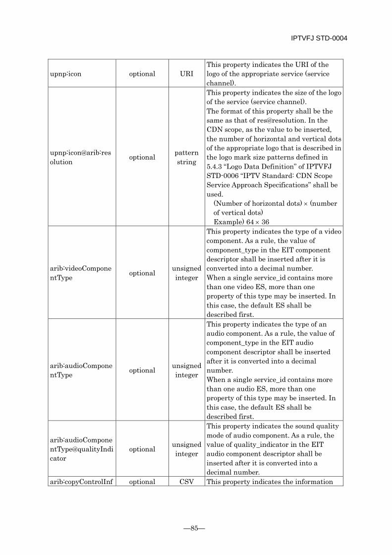
IPTVFJ STD-0004
—85—
upnp:icon optional URI This property indicates the URI of the logo of the appropriate service (service channel).
upnp:icon@arib:resolution optional pattern
string
This property indicates the size of the logo of the service (service channel). The format of this property shall be the same as that of res@resolution. In the CDN scope, as the value to be inserted, the number of horizontal and vertical dots of the appropriate logo that is described in the logo mark size patterns defined in 5.4.3 “Logo Data Definition” of IPTVFJ STD-0006 “IPTV Standard: CDN Scope Service Approach Specifications” shall be used.
(Number of horizontal dots) × (number of vertical dots) Example) 64 × 36
arib:videoComponentType optional unsigned
integer
This property indicates the type of a video component. As a rule, the value of component_type in the EIT component descriptor shall be inserted after it is converted into a decimal number. When a single service_id contains more than one video ES, more than one property of this type may be inserted. In this case, the default ES shall be described first.
arib:audioComponentType optional unsigned
integer
This property indicates the type of an audio component. As a rule, the value of component_type in the EIT audio component descriptor shall be inserted after it is converted into a decimal number. When a single service_id contains more than one audio ES, more than one property of this type may be inserted. In this case, the default ES shall be described first.
arib:audioComponentType@qualityIndicator
optional unsigned integer
This property indicates the sound quality mode of audio component. As a rule, the value of quality_indicator in the EIT audio component descriptor shall be inserted after it is converted into a decimal number.
arib:copyControlInf optional CSV This property indicates the information
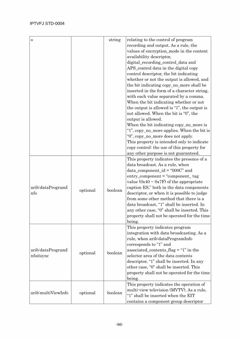
IPTVFJ STD-0004
-86-
o string relating to the control of program recording and output. As a rule, the values of encryption_mode in the content availability descriptor, digital_recording_control_data and APS_control data in the digital copy control descriptor, the bit indicating whether or not the output is allowed, and the bit indicating copy_no_more shall be inserted in the form of a character string, with each value separated by a comma. When the bit indicating whether or not the output is allowed is “1”, the output is not allowed. When the bit is “0”, the output is allowed. When the bit indicating copy_no_more is “1”, copy_no_more applies. When the bit is “0”, copy_no_more does not apply. This property is intended only to indicate copy control: the use of this property for any other purpose is not guaranteed.
arib:dataProgramInfo optional boolean
This property indicates the presence of a data broadcast. As a rule, when data_component_id = “000C” and entry_component = “component_ tag value (0x40 ~ 0x7F) of the appropriate caption ES,” both in the data components descriptor, or when it is possible to judge from some other method that there is a data broadcast, “1” shall be inserted. In any other case, “0” shall be inserted. This property shall not be operated for the time being.
arib:dataProgramInfo@sync optional boolean
This property indicates program integration with data broadcasting. As a rule, when arib:dataProgramInfo corresponds to “1” and associated_contents_flag = “1” in the selector area of the data contents descriptor, “1” shall be inserted. In any other case, “0” shall be inserted. This property shall not be operated for the time being.
arib:multiViewInfo optional boolean
This property indicates the operation of multi-view television (MVTV). As a rule, “1” shall be inserted when the EIT contains a component group descriptor
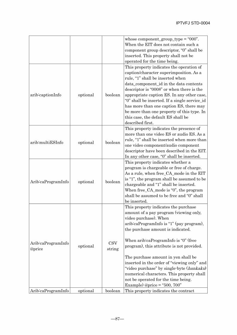
IPTVFJ STD-0004
—87—
whose component_group_type = “000”. When the EIT does not contain such a component group descriptor, “0” shall be inserted. This property shall not be operated for the time being.
arib:captionInfo optional boolean
This property indicates the operation of caption/character superimposition. As a rule, “1” shall be inserted when data_component_id in the data contents descriptor is “0008” or when there is the appropriate caption ES. In any other case, “0” shall be inserted. If a single service_id has more than one caption ES, there may be more than one property of this type. In this case, the default ES shall be described first.
arib:multiESInfo optional boolean
This property indicates the presence of more than one video ES or audio ES. As a rule, “1” shall be inserted when more than one video component/audio component descriptor have been described in the EIT. In any other case, “0” shall be inserted.
Arib:caProgramInfo optional boolean
This property indicates whether a program is chargeable or free of charge. As a rule, when free_CA_mode in the EIT is “1”, the program shall be assumed to be chargeable and “1” shall be inserted. When free_CA_mode is “0”, the program shall be assumed to be free and “0” shall be inserted.
Arib:caProgramInfo@price optional CSV
string
This property indicates the purchase amount of a pay program (viewing only, video purchase). When arib:caProgramInfo is “1” (pay program), the purchase amount is indicated. When arib:caProgramInfo is “0” (free program), this attribute is not provided. The purchase amount in yen shall be inserted in the order of “viewing only” and “video purchase” by single-byte (hankaku) numerical characters. This property shall not be operated for the time being. Example) @price = “500, 700”
Arib:caProgramInfo optional boolean This property indicates the contract
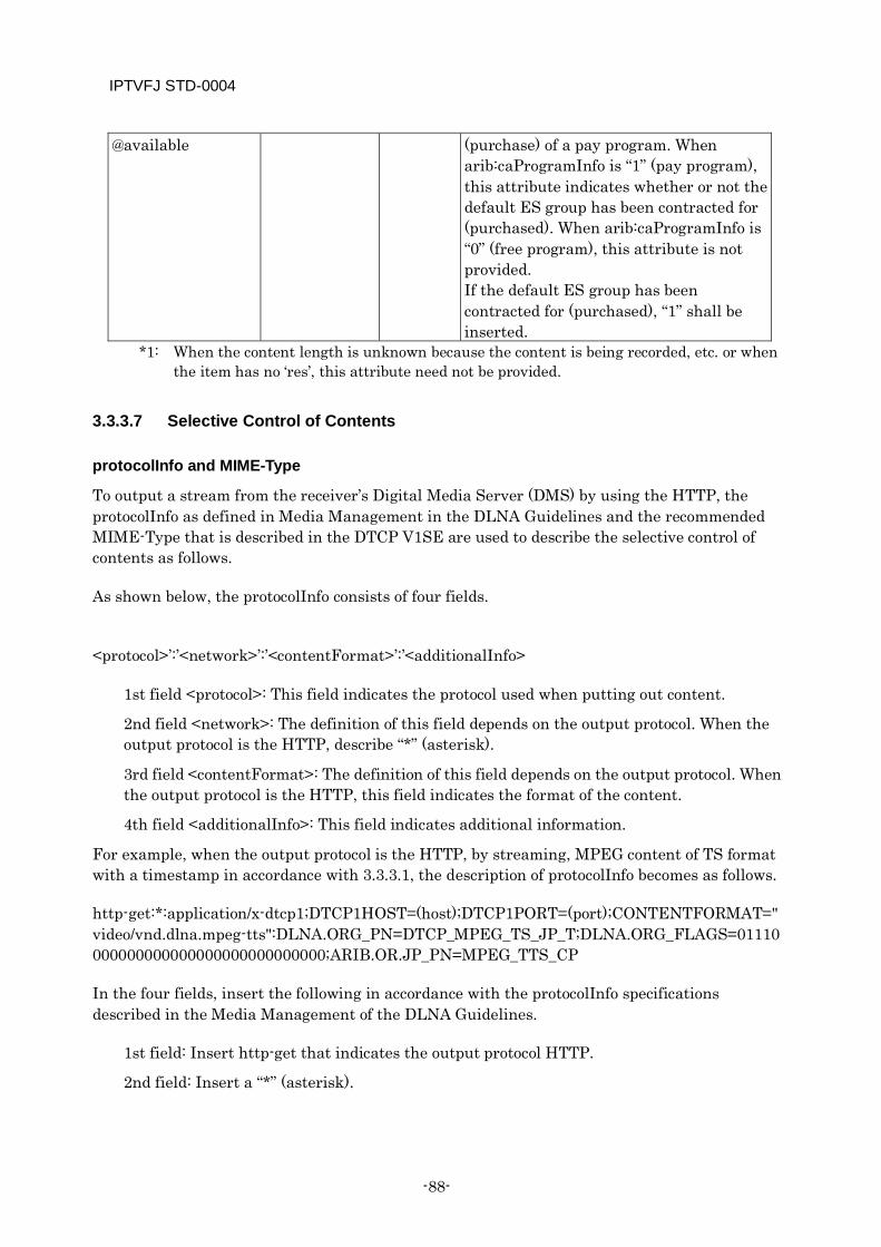
IPTVFJ STD-0004
-88-
@available (purchase) of a pay program. When arib:caProgramInfo is “1” (pay program), this attribute indicates whether or not the default ES group has been contracted for (purchased). When arib:caProgramInfo is “0” (free program), this attribute is not provided. If the default ES group has been contracted for (purchased), “1” shall be inserted.
*1: When the content length is unknown because the content is being recorded, etc. or when the item has no ‘res’, this attribute need not be provided.
3.3.3.7 Selective Control of Contents
protocolInfo and MIME-Type
To output a stream from the receiver’s Digital Media Server (DMS) by using the HTTP, the protocolInfo as defined in Media Management in the DLNA Guidelines and the recommended MIME-Type that is described in the DTCP V1SE are used to describe the selective control of contents as follows.
As shown below, the protocolInfo consists of four fields.
<protocol>’:’<network>’:’<contentFormat>’:’<additionalInfo>
1st field <protocol>: This field indicates the protocol used when putting out content.
2nd field <network>: The definition of this field depends on the output protocol. When the output protocol is the HTTP, describe “*” (asterisk).
3rd field <contentFormat>: The definition of this field depends on the output protocol. When the output protocol is the HTTP, this field indicates the format of the content.
4th field <additionalInfo>: This field indicates additional information.
For example, when the output protocol is the HTTP, by streaming, MPEG content of TS format with a timestamp in accordance with 3.3.3.1, the description of protocolInfo becomes as follows.
http-get:*:application/x-dtcp1;DTCP1HOST=(host);DTCP1PORT=(port);CONTENTFORMAT="video/vnd.dlna.mpeg-tts":DLNA.ORG_PN=DTCP_MPEG_TS_JP_T;DLNA.ORG_FLAGS=01110000000000000000000000000000;ARIB.OR.JP_PN=MPEG_TTS_CP
In the four fields, insert the following in accordance with the protocolInfo specifications described in the Media Management of the DLNA Guidelines.
1st field: Insert http-get that indicates the output protocol HTTP.
2nd field: Insert a “*” (asterisk).
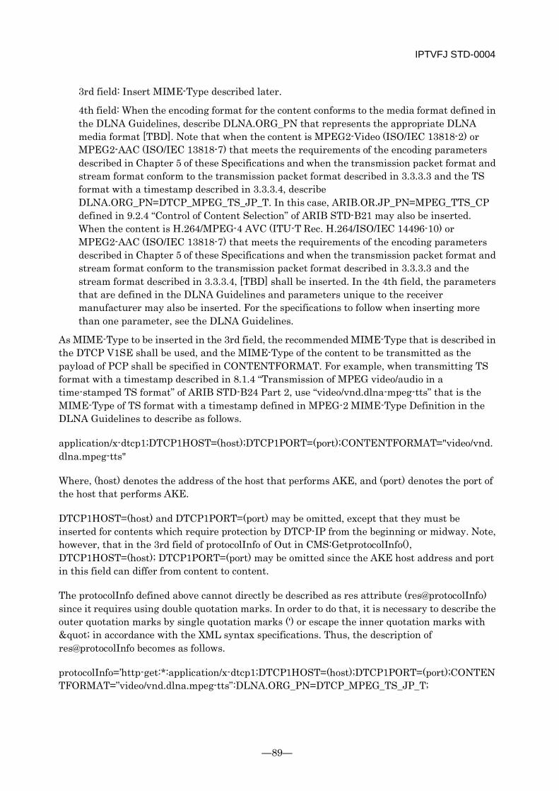
IPTVFJ STD-0004
—89—
3rd field: Insert MIME-Type described later.
4th field: When the encoding format for the content conforms to the media format defined in the DLNA Guidelines, describe DLNA.ORG_PN that represents the appropriate DLNA media format [TBD]. Note that when the content is MPEG2-Video (ISO/IEC 13818-2) or MPEG2-AAC (ISO/IEC 13818-7) that meets the requirements of the encoding parameters described in Chapter 5 of these Specifications and when the transmission packet format and stream format conform to the transmission packet format described in 3.3.3.3 and the TS format with a timestamp described in 3.3.3.4, describe DLNA.ORG_PN=DTCP_MPEG_TS_JP_T. In this case, ARIB.OR.JP_PN=MPEG_TTS_CP defined in 9.2.4 “Control of Content Selection” of ARIB STD-B21 may also be inserted. When the content is H.264/MPEG-4 AVC (ITU-T Rec. H.264/ISO/IEC 14496-10) or MPEG2-AAC (ISO/IEC 13818-7) that meets the requirements of the encoding parameters described in Chapter 5 of these Specifications and when the transmission packet format and stream format conform to the transmission packet format described in 3.3.3.3 and the stream format described in 3.3.3.4, [TBD] shall be inserted. In the 4th field, the parameters that are defined in the DLNA Guidelines and parameters unique to the receiver manufacturer may also be inserted. For the specifications to follow when inserting more than one parameter, see the DLNA Guidelines.
As MIME-Type to be inserted in the 3rd field, the recommended MIME-Type that is described in the DTCP V1SE shall be used, and the MIME-Type of the content to be transmitted as the payload of PCP shall be specified in CONTENTFORMAT. For example, when transmitting TS format with a timestamp described in 8.1.4 “Transmission of MPEG video/audio in a time-stamped TS format” of ARIB STD-B24 Part 2, use “video/vnd.dlna-mpeg-tts” that is the MIME-Type of TS format with a timestamp defined in MPEG-2 MIME-Type Definition in the DLNA Guidelines to describe as follows.
application/x-dtcp1;DTCP1HOST=(host);DTCP1PORT=(port);CONTENTFORMAT="video/vnd.dlna.mpeg-tts"
Where, (host) denotes the address of the host that performs AKE, and (port) denotes the port of the host that performs AKE.
DTCP1HOST=(host) and DTCP1PORT=(port) may be omitted, except that they must be inserted for contents which require protection by DTCP-IP from the beginning or midway. Note, however, that in the 3rd field of protocolInfo of Out in CMS:GetprotocolInfo(), DTCP1HOST=(host); DTCP1PORT=(port) may be omitted since the AKE host address and port in this field can differ from content to content.
The protocolInfo defined above cannot directly be described as res attribute (res@protocolInfo) since it requires using double quotation marks. In order to do that, it is necessary to describe the outer quotation marks by single quotation marks (') or escape the inner quotation marks with " in accordance with the XML syntax specifications. Thus, the description of res@protocolInfo becomes as follows.
protocolInfo=’http-get:*:application/x-dtcp1;DTCP1HOST=(host);DTCP1PORT=(port);CONTENTFORMAT=”video/vnd.dlna.mpeg-tts”:DLNA.ORG_PN=DTCP_MPEG_TS_JP_T;
IPTVFJ STD-0004
-90-
DLNA.ORG_FLAGS=01110000000000000000000000000000;ARIB.OR.JP_PN=MPEG_TTS_CP’
or
protocolInfo=”http-get:*:application/x-dtcp1;DTCP1HOST=(host);DTCP1PORT=(port);CONTENTFORMAT="video/vnd.dlna.mpeg-tts":DLNA.ORG_PN=DTCP_MPEG_TS_JP_T; DLNA.ORG_FLAGS=01110000000000000000000000000000;ARIB.OR.JP_PN=MPEG_TTS_CP”
URI of content protected by DTCP-IP
For the URI of the content protected by DTCP-IP that is described as the value of res in the tuner description, the recommended URI format that is described in the DTCP V1SE need not be used.
Content-Type header field of HTTP header
In the HTTP request or HTTP response relating to content protected by DTCP-IP, the address and port number of the host that executes AKE shall be included in the Content-Type header field inserted in the HTTP header as defined in the DTCP V1SE. This MIME-Type is the same as the MIME-Type that is described in the 3rd field of protocolInfo mentioned earlier.
Content-Type:application/x-dtcp1;DTCP1HOST=(host);DTCP1PORT=(port);CONTENTFORMAT=“video/vnd.dlna.mpeg-tts“
Access to content with range specification
When the receiver supports the access to content with a range specified by TimeSeekRange.dlna.org described in the DLNA Guidelines, it shall follow the related specifications of the DLNA Guidelines.
When the receiver supports the access to content with a range specified by Range.dtcp.com described in the DTCP V1SE, it shall follow the specifications described below.
When the receiver responds to the access to content with a range specified by Range.dtcp.com, it shall describe, in the 4th field of res@protocolInfo of the appropriate content, cleartextbyteseek-full or lop-cleartextbytes flag of DLNA.ORG_FLAGS defined in the DLNA Guidelines as True. “ARIB.OR.JP_OP=1” as defined in 9.2.4 “Control of Content Selection” of ARIB STD-B21 may also be inserted. For contents to which the receiver does not respond, the parameter ARIB.OR.JP_OP shall not be inserted.
The format of Range.dtcp.com shall be as follows.
Range.dtcp.com = "Range.dtcp.com" ":" range-specifier
range-specifier = byte-range-specifier
byte-range-specifier = bytes-unit "=" byte-range-set
bytes-unit = "bytes"
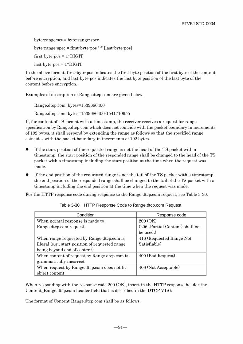
IPTVFJ STD-0004
—91—
byte-range-set = byte-range-spec
byte-range-spec = first-byte-pos "-" [last-byte-pos]
first-byte-pos = 1*DIGIT
last-byte-pos = 1*DIGIT
In the above format, first-byte-pos indicates the first byte position of the first byte of the content before encryption, and last-byte-pos indicates the last byte position of the last byte of the content before encryption.
Examples of description of Range.dtcp.com are given below.
Range.dtcp.com: bytes=1539686400-
Range.dtcp.com: bytes=1539686400-1541710655
If, for content of TS format with a timestamp, the receiver receives a request for range specification by Range.dtcp.com which does not coincide with the packet boundary in increments of 192 bytes, it shall respond by extending the range as follows so that the specified range coincides with the packet boundary in increments of 192 bytes.
If the start position of the requested range is not the head of the TS packet with a timestamp, the start position of the responded range shall be changed to the head of the TS packet with a timestamp including the start position at the time when the request was made.
If the end position of the requested range is not the tail of the TS packet with a timestamp, the end position of the responded range shall be changed to the tail of the TS packet with a timestamp including the end position at the time when the request was made.
For the HTTP response code during response to the Range.dtcp.com request, see Table 3-30.
Table 3-30 HTTP Response Code to Range.dtcp.com Request
Condition Response code When normal response is made to Range.dtcp.com request
200 (OK) (206 (Partial Content) shall not be used.)
When range requested by Range.dtcp.com is illegal (e.g., start position of requested range being beyond end of content)
416 (Requested Range Not Satisfiable)
When content of request by Range.dtcp.com is grammatically incorrect
400 (Bad Request)
When request by Range.dtcp.com does not fit object content
406 (Not Acceptable)
When responding with the response code 200 (OK), insert in the HTTP response header the Content_Range.dtcp.com header field that is described in the DTCP V1SE.
The format of Content-Range.dtcp.com shall be as follows.

IPTVFJ STD-0004
-92-
Content-Range.dtcp.com = "Content-Range.dtcp.com" ":" content-range-spec
content-range-spec = byte-content-range-spec
byte-content-range-spec = bytes-unit SP byte-range-resp-spec "/" ( instance-length | "*" )
bytes-unit = "bytes"
byte-range-resp-spec = first-byte-pos "-" last-byte-pos
first-byte-pos = 1*DIGIT
last-byte-pos = 1*DIGIT
instance-length = 1*DIGIT
In the above format, the first-byte-pos indicates the position of the first byte of the content before encryption, and the last-byte-pos indicates the position of the last byte of the content before encryption.
The instance-length indicates the overall size of the content before encryption. Note that if the overall size is difficult to calculate, “*” may be used in the Content-Range.
An example of description of Content-Range.dtcp.com is given below.
Content-Range.dtcp.com: bytes 1539686400-1541710655/9238118400
When accessing content of TS format with a timestamp in the receiver by using Content-Range.dtcp.com, it is desirable to specify the range that coincides with the packet boundary of TS format with a timestamp in increments of 192 bytes.
3.3.3.8 Specifications on Conversion of Extended Characters Used in Tuner Description
The character code that is used in the receiver tuner description shall be in accordance with the specifications described in 9.2.3 “Tuner Description Specifications” of ARIB STD-B21. However, concerning the group of additional symbols defined in 7.1 “JIS 8bit Character Code” of ARIB STD-B24, Volume 1, Part 2, it shall be in accordance with Table 7-19 “Code Values for Added Symbols Set” in ARIB STD-B24, Volume 1, Part 2.
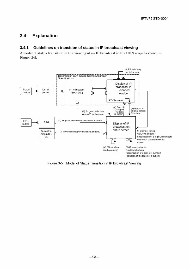
IPTVFJ STD-0004
—93—
3.4 Explanation
3.4.1 Guidelines on transition of status in IP broadcast viewing A model of status transition in the viewing of an IP broadcast in the CDN scope is shown in Figure 3-5.
Figure 3-5 Model of Status Transition in IP Broadcast Viewing
EPG EPG
Portal button
List of portals
Described in CDN Scope Service Approach Specifications
IPTV browser (EPG, etc.)
Display of IP broadcast in
L-shaped window
IPTV browser
(1) Program selection (Arrow/Enter buttons)
(6) Start of L-shaped
window (d button)
(7) Return to original screen (d button)
EPG button
(2) Program selection (Arrow/Enter buttons)
Terrestrial digital/BS/
CS
(3) NW switching (NW switching buttons)
Display of IP broadcast on entire screen
(4) ES switching (audio/caption)
(9) Channel tuning (Up/Down buttons) (specification of 3-digit CH number) (one-touch channel selection button)
(5) Channel selection (Up/Down buttons) (specification of 3-digit CH number) (selection at the touch of a button)
(8) ES switching (audio/caption)
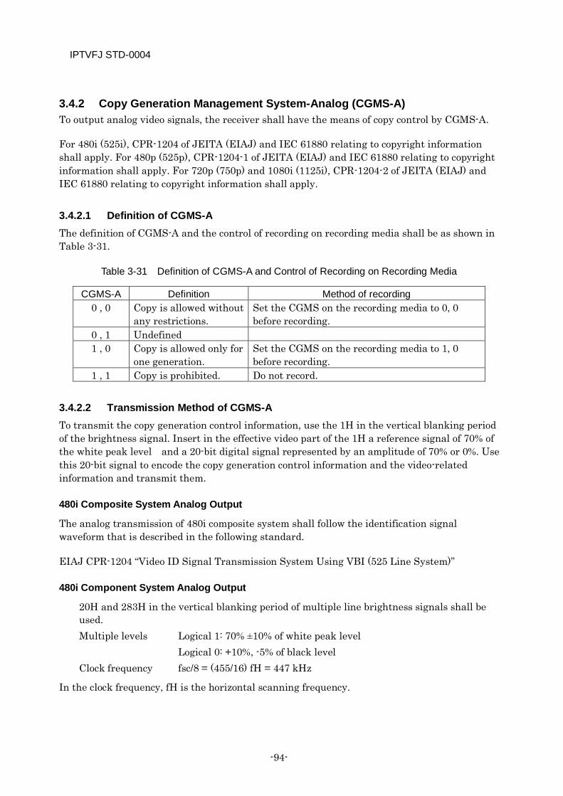
IPTVFJ STD-0004
-94-
3.4.2 Copy Generation Management System-Analog (CGMS-A) To output analog video signals, the receiver shall have the means of copy control by CGMS-A.
For 480i (525i), CPR-1204 of JEITA (EIAJ) and IEC 61880 relating to copyright information shall apply. For 480p (525p), CPR-1204-1 of JEITA (EIAJ) and IEC 61880 relating to copyright information shall apply. For 720p (750p) and 1080i (1125i), CPR-1204-2 of JEITA (EIAJ) and IEC 61880 relating to copyright information shall apply.
3.4.2.1 Definition of CGMS-A The definition of CGMS-A and the control of recording on recording media shall be as shown in Table 3-31.
Table 3-31 Definition of CGMS-A and Control of Recording on Recording Media
CGMS-A Definition Method of recording 0 , 0 Copy is allowed without
any restrictions. Set the CGMS on the recording media to 0, 0 before recording.
0 , 1 Undefined 1 , 0 Copy is allowed only for
one generation. Set the CGMS on the recording media to 1, 0 before recording.
1 , 1 Copy is prohibited. Do not record.
3.4.2.2 Transmission Method of CGMS-A To transmit the copy generation control information, use the 1H in the vertical blanking period of the brightness signal. Insert in the effective video part of the 1H a reference signal of 70% of the white peak level and a 20-bit digital signal represented by an amplitude of 70% or 0%. Use this 20-bit signal to encode the copy generation control information and the video-related information and transmit them.
480i Composite System Analog Output
The analog transmission of 480i composite system shall follow the identification signal waveform that is described in the following standard.
EIAJ CPR-1204 “Video ID Signal Transmission System Using VBI (525 Line System)”
480i Component System Analog Output
20H and 283H in the vertical blanking period of multiple line brightness signals shall be used. Multiple levels Logical 1: 70% ±10% of white peak level Logical 0: +10%, -5% of black level Clock frequency fsc/8 = (455/16) fH = 447 kHz
In the clock frequency, fH is the horizontal scanning frequency.

IPTVFJ STD-0004
—95—
The transmission signal waveform is shown in Figure 3-6. The cumulative error time from the startup of Ref to bit 20 shall be within 0.44 μs.
Figure 3-6 480i Component System Identification Signal Waveform
480p Component System Analog Output
The analog transmission of 480p component system shall follow the identification signal waveform that is described in the following standard.
EIAJ CPR-1204-1 “Video ID Signal Transmission System Using VBI (525p System)”
720p Component System Analog Output
The analog transmission of 720p component system shall follow the identification signal waveform that is described in the following standard.
EIAJ CPR-1204-2 “Video ID Signal Transmission System Using VBI (750p/1125i System)”
1080i Component System Analog Output
The analog transmission of 1080i component system shall follow the identification signal waveform that is described in the following standard.
EIAJ CPR-1204-2 “Video ID Signal Transmission System Using VBI (750p/1125i System)”
3.4.2.3 Allocation of Identification Signal The identification signal consists of 20 bits of information, which is divided into WORD0 (2 bits), WORD1 (4 bits), WORD2 (8 bits) and CRCC (6 bits).
The signal configuration is described in detail below. The unspecified bits shall be handled as unused (“0”).
Ref bit3 bit20 70%
+700mV
0mV
50% T±50ns
T=1/(fsc/8)=2.235µs 22T
Logical 0: +10%, -5% of black level
11.2µs±0.3µs -300mV
49.1µs±0.44µs
bit2 bit1 Logical 1: 70% ±10% of white peak level
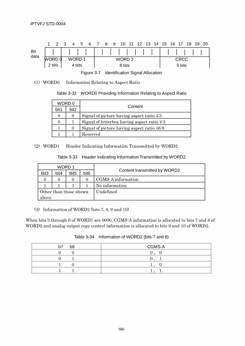
IPTVFJ STD-0004
-96-
Figure 3-7 Identification Signal Allocation
(1) WORD0 Information Relating to Aspect Ratio
Table 3-32 WORD0 Providing Information Relating to Aspect Ratio
WORD 0 Content
bit1 bit2 0 0 Signal of picture having aspect ratio 4:3 0 1 Signal of letterbox having aspect ratio 4:3 1 0 Signal of picture having aspect ratio 16:9 1 1 Reserved
(2) WORD1 Header Indicating Information Transmitted by WORD2
Table 3-33 Header Indicating Information Transmitted by WORD2
WORD 1 Content transmitted by WORD2
Bit3 bit4 Bit5 bit6 0 0 0 0 CGMS-A information 1 1 1 1 No information
Other than those shown above
Undefined
(3) Information of WORD2 (bits 7, 8, 9 and 10)
When bits 3 through 6 of WORD1 are 0000, CGMS-A information is allocated to bits 7 and 8 of WORD2 and analog output copy control information is allocated to bits 9 and 10 of WORD2.
Table 3-34 Information of WORD2 (bits 7 and 8)
b7 b8 CGMS-A 0 0 0 , 0 0 1 0 , 1 1 0 1 , 0 1 1 1 , 1
WORD 2 8 bits
CRCC 6 bits
Bit data
1 2 3 4 5 6 7 8 9 10 11 12 13 14 15 16 17 18 19 20
WORD 1 4 bits
WORD 0 2 bits
IPTVFJ STD-0004
—97—
3.4.3 Guidelines on Display of IP Broadcasting Programs Concerning the display of an IP broadcast program, it is desirable that the receiver should observe the following matters. When the receiver has the function of storing data and/or the function of controlling an external recorder, it should also observe the following matters.
The receiver shall not use IP broadcast signals or descriptors, data, etc. included in IP broadcast signals, etc. to implement the function of automatically cutting or skipping announcements, advertisements, etc. or automatically controlling the storage function and external recorder. Note that this does not apply to the fast forward play, pause, etc. performed by the user.
During presentation of an IP broadcast program, the receiver shall not intentionally mix entirely irrelevant contents, etc. in the program or present them together with the program. For example, if, during presentation of an IP broadcast program, the receiver intentionally mixes in the program some content, announcement or advertisement that has nothing to do with the program, there is a fear that the viewer may misunderstand that the content, announcement or advertisement is an inseparable part of the program. Generating a situation where the viewer misunderstands that the television broadcast screen and the Internet browser screen are one and the same thing applies to this fear. Note, however, that the receiver is allowed to have the capability to present multiple contents on one screen at a time through the viewer’s operation (e.g., 2-screen display or segmented-screen display). The receiver is also allowed to temporarily display information about the viewer’s operation and the receiver’s condition, such as the channel number of IP broadcast, on condition that the information displayed can be erased automatically or manually.
During presentation of an IP broadcast program, the receiver shall not play any audio that has nothing to do with the program, even if the audio is soundless. For example, the receiver shall not play background music (BGM) that is totally irrelevant to the broadcast program or content being presented.
3.4.4 Specifications on Use of SI by Receiver Concerning the use of Service Information (SI), the receiver shall observe the following specifications.
The receiver must not be equipped with the capability to output only SI that it obtains. Note, however, that this specification does not apply when the receiver outputs SI relating to specific content for the purpose of duplicating the content privately.
The receiver must not be equipped with the capability to display SI together with any content that has nothing to do with the SI. For example, the receiver shall not display in the program table any content (e.g., advertisement) that is irrelevant to the programs.
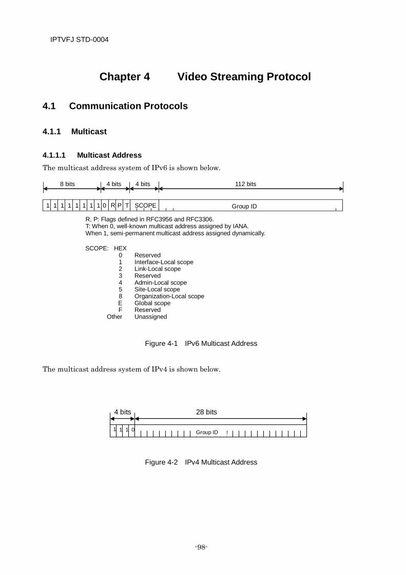
IPTVFJ STD-0004
-98-
Chapter 4 Video Streaming Protocol
4.1 Communication Protocols
4.1.1 Multicast
4.1.1.1 Multicast Address The multicast address system of IPv6 is shown below.
Figure 4-1 IPv6 Multicast Address
The multicast address system of IPv4 is shown below.
Figure 4-2 IPv4 Multicast Address
Group ID 1 1 1 1 1 1 1 1 0 R P T SCOPE
8 bits 4 bits 4 bits 112 bits
SCOPE: HEX 0 Reserved 1 Interface-Local scope 2 Link-Local scope 3 Reserved 4 Admin-Local scope 5 Site-Local scope 8 Organization-Local scope E Global scope F Reserved Other Unassigned
R, P: Flags defined in RFC3956 and RFC3306. T: When 0, well-known multicast address assigned by IANA. When 1, semi-permanent multicast address assigned dynamically.
1 1 1 0
4 bits 28 bits
Group ID
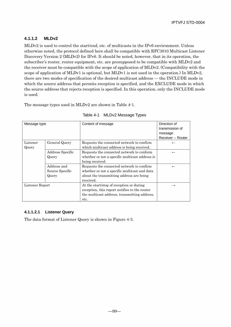
IPTVFJ STD-0004
—99—
4.1.1.2 MLDv2 MLDv2 is used to control the start/end, etc. of multicasts in the IPv6 environment. Unless otherwise noted, the protocol defined here shall be compatible with RFC3810 Multicast Listener Discovery Version 2 (MLDv2) for IPv6. It should be noted, however, that in its operation, the subscriber’s router, router equipment, etc. are presupposed to be compatible with MLDv2 and the receiver must be compatible with the scope of application of MLDv2. (Compatibility with the scope of application of MLDv1 is optional, but MLDv1 is not used in the operation.) In MLDv2, there are two modes of specification of the desired multicast address — the INCLUDE mode in which the source address that permits reception is specified, and the EXCLUDE mode in which the source address that rejects reception is specified. In this operation, only the INCLUDE mode is used.
The message types used in MLDv2 are shown in Table 4-1.
Table 4-1 MLDv2 Message Types
Message type Content of message Direction of transmission of message Receiver -- Router
Listener Query
General Query Requests the connected network to confirm which multicast address is being received.
←
Address Specific Query
Requests the connected network to conform whether or not a specific multicast address is being received.
←
Address and Source Specific Query
Requests the connected network to confirm whether or not a specific multicast and data about the transmitting address are being received.
←
Listener Report At the start/stop of reception or during reception, this report notifies to the router the multicast address, transmitting address, etc.
→
4.1.1.2.1 Listener Query
The data format of Listener Query is shown in Figure 4-3.
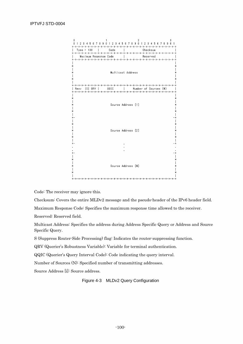
IPTVFJ STD-0004
-100-
Code: The receiver may ignore this.
Checksum: Covers the entire MLDv2 message and the pseudo-header of the IPv6 header field.
Maximum Response Code: Specifies the maximum response time allowed to the receiver.
Reserved: Reserved field.
Multicast Address: Specifies the address during Address Specific Query or Address and Source Specific Query.
S (Suppress Router-Side Processing) flag: Indicates the router-suppressing function.
QRV (Querier’s Robustness Variable): Variable for terminal authentication.
QQIC (Querier’s Query Interval Code): Code indicating the query interval.
Number of Sources (N): Specified number of transmitting addresses.
Source Address [i]: Source address.
Figure 4-3 MLDv2 Query Configuration
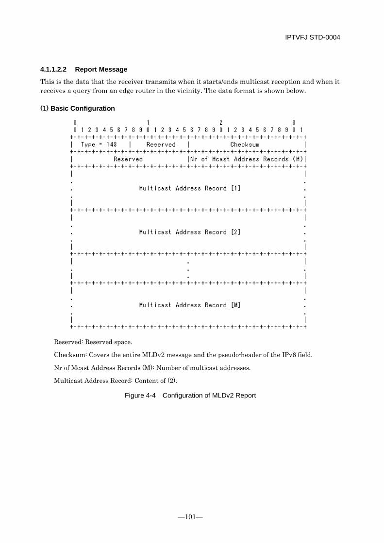
IPTVFJ STD-0004
—101—
4.1.1.2.2 Report Message
This is the data that the receiver transmits when it starts/ends multicast reception and when it receives a query from an edge router in the vicinity. The data format is shown below.
(1) Basic Configuration
Reserved: Reserved space.
Checksum: Covers the entire MLDv2 message and the pseudo-header of the IPv6 field.
Nr of Mcast Address Records (M): Number of multicast addresses.
Multicast Address Record: Content of (2).
Figure 4-4 Configuration of MLDv2 Report
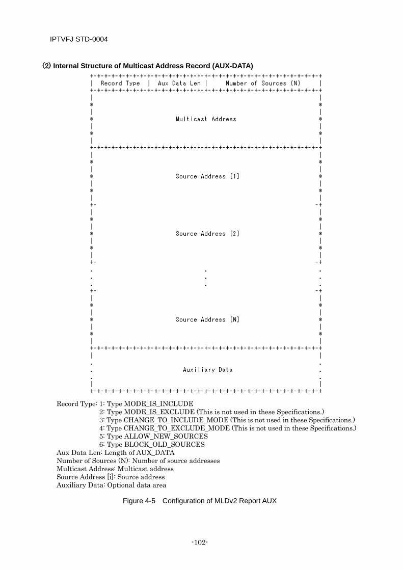
IPTVFJ STD-0004
-102-
(2) Internal Structure of Multicast Address Record (AUX-DATA)
Record Type: 1: Type MODE_IS_INCLUDE 2: Type MODE_IS_EXCLUDE (This is not used in these Specifications.) 3: Type CHANGE_TO_INCLUDE_MODE (This is not used in these Specifications.) 4: Type CHANGE_TO_EXCLUDE_MODE (This is not used in these Specifications.) 5: Type ALLOW_NEW_SOURCES 6: Type BLOCK_OLD_SOURCES Aux Data Len: Length of AUX_DATA Number of Sources (N): Number of source addresses Multicast Address: Multicast address Source Address [i]: Source address Auxiliary Data: Optional data area
Figure 4-5 Configuration of MLDv2 Report AUX
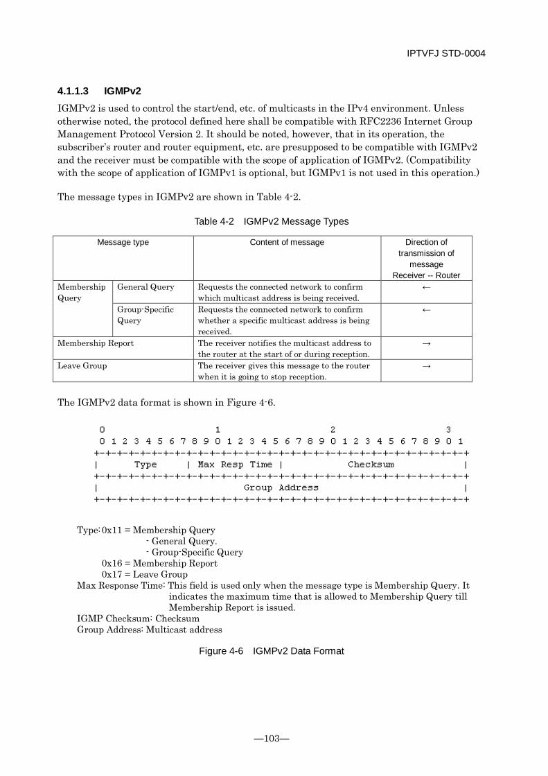
IPTVFJ STD-0004
—103—
4.1.1.3 IGMPv2 IGMPv2 is used to control the start/end, etc. of multicasts in the IPv4 environment. Unless otherwise noted, the protocol defined here shall be compatible with RFC2236 Internet Group Management Protocol Version 2. It should be noted, however, that in its operation, the subscriber’s router and router equipment, etc. are presupposed to be compatible with IGMPv2 and the receiver must be compatible with the scope of application of IGMPv2. (Compatibility with the scope of application of IGMPv1 is optional, but IGMPv1 is not used in this operation.)
The message types in IGMPv2 are shown in Table 4-2.
Table 4-2 IGMPv2 Message Types
Message type Content of message Direction of transmission of
message Receiver -- Router
Membership Query
General Query Requests the connected network to confirm which multicast address is being received.
←
Group-Specific Query
Requests the connected network to confirm whether a specific multicast address is being received.
←
Membership Report The receiver notifies the multicast address to the router at the start of or during reception.
→
Leave Group The receiver gives this message to the router when it is going to stop reception.
→
The IGMPv2 data format is shown in Figure 4-6.
Type: 0x11 = Membership Query - General Query. - Group-Specific Query 0x16 = Membership Report 0x17 = Leave Group Max Response Time: This field is used only when the message type is Membership Query. It
indicates the maximum time that is allowed to Membership Query till Membership Report is issued.
IGMP Checksum: Checksum Group Address: Multicast address
Figure 4-6 IGMPv2 Data Format
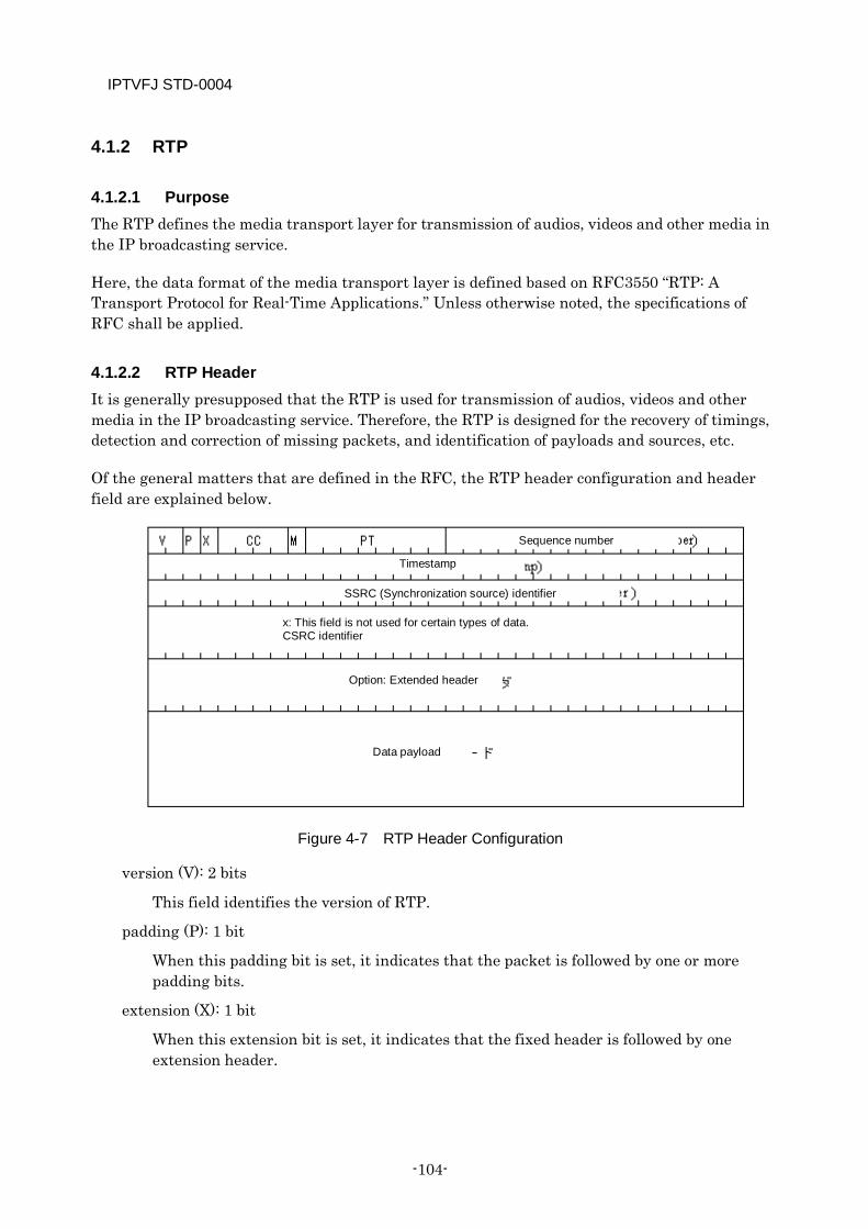
IPTVFJ STD-0004
-104-
4.1.2 RTP
4.1.2.1 Purpose The RTP defines the media transport layer for transmission of audios, videos and other media in the IP broadcasting service.
Here, the data format of the media transport layer is defined based on RFC3550 “RTP: A Transport Protocol for Real-Time Applications.” Unless otherwise noted, the specifications of RFC shall be applied.
4.1.2.2 RTP Header It is generally presupposed that the RTP is used for transmission of audios, videos and other media in the IP broadcasting service. Therefore, the RTP is designed for the recovery of timings, detection and correction of missing packets, and identification of payloads and sources, etc.
Of the general matters that are defined in the RFC, the RTP header configuration and header field are explained below.
Figure 4-7 RTP Header Configuration
version (V): 2 bits
This field identifies the version of RTP.
padding (P): 1 bit
When this padding bit is set, it indicates that the packet is followed by one or more padding bits.
extension (X): 1 bit
When this extension bit is set, it indicates that the fixed header is followed by one extension header.
Option: Extended header
Sequence number
Timestamp
SSRC (Synchronization source) identifier
x: This field is not used for certain types of data. CSRC identifier
Data payload
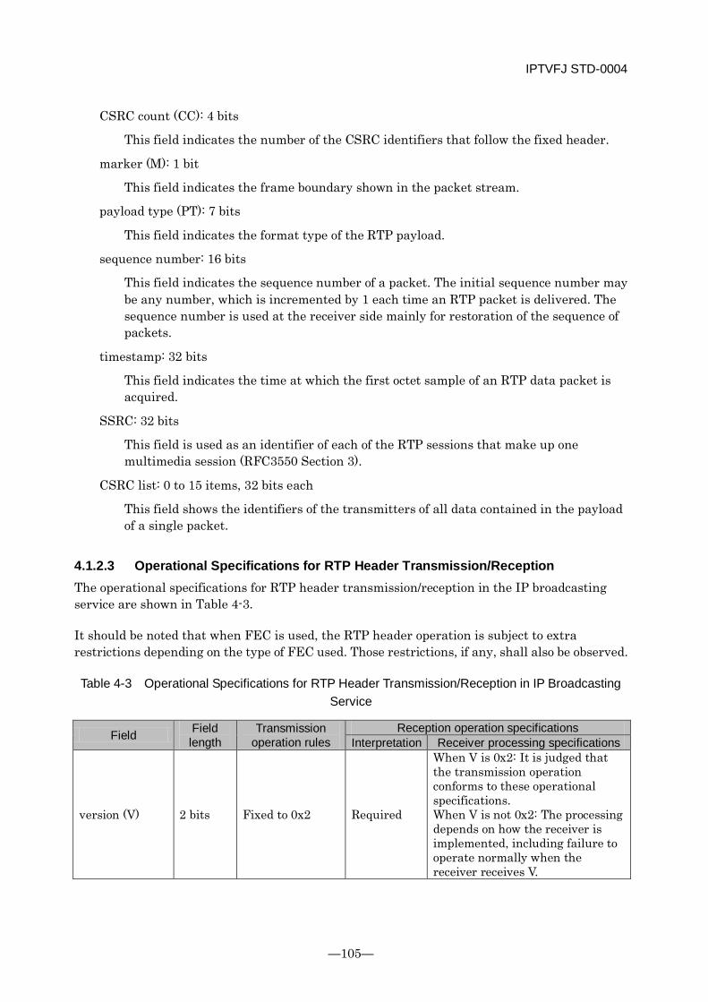
IPTVFJ STD-0004
—105—
CSRC count (CC): 4 bits
This field indicates the number of the CSRC identifiers that follow the fixed header.
marker (M): 1 bit
This field indicates the frame boundary shown in the packet stream.
payload type (PT): 7 bits
This field indicates the format type of the RTP payload.
sequence number: 16 bits
This field indicates the sequence number of a packet. The initial sequence number may be any number, which is incremented by 1 each time an RTP packet is delivered. The sequence number is used at the receiver side mainly for restoration of the sequence of packets.
timestamp: 32 bits
This field indicates the time at which the first octet sample of an RTP data packet is acquired.
SSRC: 32 bits
This field is used as an identifier of each of the RTP sessions that make up one multimedia session (RFC3550 Section 3).
CSRC list: 0 to 15 items, 32 bits each
This field shows the identifiers of the transmitters of all data contained in the payload of a single packet.
4.1.2.3 Operational Specifications for RTP Header Transmission/Reception The operational specifications for RTP header transmission/reception in the IP broadcasting service are shown in Table 4-3.
It should be noted that when FEC is used, the RTP header operation is subject to extra restrictions depending on the type of FEC used. Those restrictions, if any, shall also be observed.
Table 4-3 Operational Specifications for RTP Header Transmission/Reception in IP Broadcasting Service
Field Field length
Transmission operation rules
Reception operation specifications Interpretation Receiver processing specifications
version (V) 2 bits Fixed to 0x2 Required
When V is 0x2: It is judged that the transmission operation conforms to these operational specifications. When V is not 0x2: The processing depends on how the receiver is implemented, including failure to operate normally when the receiver receives V.
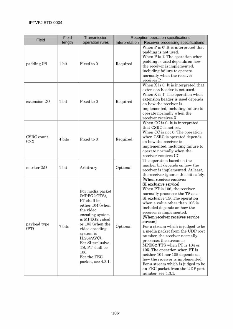
IPTVFJ STD-0004
-106-
Field Field length
Transmission operation rules
Reception operation specifications Interpretation Receiver processing specifications
padding (P) 1 bit Fixed to 0 Required
When P is 0: It is interpreted that padding is not used. When P is 1: The operation when padding is used depends on how the receiver is implemented, including failure to operate normally when the receiver receives P.
extension (X) 1 bit Fixed to 0 Required
When X is 0: It is interpreted that extension header is not used. When X is 1: The operation when extension header is used depends on how the receiver is implemented, including failure to operate normally when the receiver receives X.
CSRC count (CC) 4 bits Fixed to 0 Required
When CC is 0: It is interpreted that CSRC is not set. When CC is not 0: The operation when CSRC is operated depends on how the receiver is implemented, including failure to operate normally when the receiver receives CC.
marker (M) 1 bit Arbitrary Optional The operation based on the marker bit depends on how the receiver is implemented. At least, the receiver ignores this bit safely.
payload type (PT) 7 bits
For media packet (MPEG2-TTS), PT shall be either 104 (when the video encoding system is MPEG2 video) or 105 (when the video encoding system is H.264/AVC). For SI-exclusive TS, PT shall be 106. For the FEC packet, see 4.3.1.
Optional
[When receiver receives SI-exclusive service] When PT is 106, the receiver normally processes the TS as a SI-exclusive TS. The operation when a value other than 106 is included depends on how the receiver is implemented. [When receiver receives service stream] For a stream which is judged to be a media packet from the UDP port number, the receiver normally processes the stream as MPEG2-TTS when PT is 104 or 105. The operation when PT is neither 104 nor 105 depends on how the receiver is implemented. For a stream which is judged to be an FEC packet from the UDP port number, see 4.3.1.
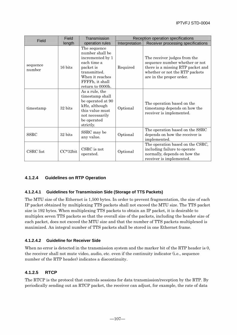
IPTVFJ STD-0004
—107—
Field Field length
Transmission operation rules
Reception operation specifications Interpretation Receiver processing specifications
sequence number 16 bits
The sequence number shall be incremented by 1 each time a packet is transmitted. When it reaches FFFFh, it shall return to 0000h.
Required
The receiver judges from the sequence number whether or not there is a missing RTP packet and whether or not the RTP packets are in the proper order.
timestamp 32 bits
As a rule, the timestamp shall be operated at 90 kHz, although this value must not necessarily be operated strictly.
Optional The operation based on the timestamp depends on how the receiver is implemented.
SSRC 32 bits SSRC may be any value. Optional
The operation based on the SSRC depends on how the receiver is implemented.
CSRC list CC*32bit CSRC is not operated. Optional
The operation based on the CSRC, including failure to operate normally, depends on how the receiver is implemented.
4.1.2.4 Guidelines on RTP Operation
4.1.2.4.1 Guidelines for Transmission Side (Storage of TTS Packets)
The MTU size of the Ethernet is 1,500 bytes. In order to prevent fragmentation, the size of each IP packet obtained by multiplexing TTS packets shall not exceed the MTU size. The TTS packet size is 192 bytes. When multiplexing TTS packets to obtain an IP packet, it is desirable to multiplex seven TTS packets so that the overall size of the packets, including the header size of each packet, does not exceed the MTU size and that the number of TTS packets multiplexed is maximized. An integral number of TTS packets shall be stored in one Ethernet frame.
4.1.2.4.2 Guideline for Receiver Side
When no error is detected in the transmission system and the marker bit of the RTP header is 0, the receiver shall not mute video, audio, etc. even if the continuity indicator (i.e., sequence number of the RTP header) indicates a discontinuity.
4.1.2.5 RTCP The RTCP is the protocol that controls sessions for data transmission/reception by the RTP. By periodically sending out an RTCP packet, the receiver can adjust, for example, the rate of data
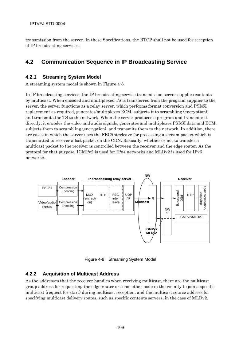
IPTVFJ STD-0004
-108-
transmission from the server. In these Specifications, the RTCP shall not be used for reception of IP broadcasting services.
4.2 Communication Sequence in IP Broadcasting Service
4.2.1 Streaming System Model A streaming system model is shown in Figure 4-8.
In IP broadcasting services, the IP broadcasting service transmission server supplies contents by multicast. When encoded and multiplexed TS is transferred from the program supplier to the server, the server functions as a relay server, which performs format conversion and PSI/SI replacement as required, generates/multiplexes ECM, subjects it to scrambling (encryption), and transmits the TS to the network. When the server produces a program and transmits it directly, it encodes the video and audio signals, generates and multiplexes PSI/SI data and ECM, subjects them to scrambling (encryption), and transmits them to the network. In addition, there are cases in which the server uses the FEC/interleave for processing a stream packet which is transmitted to recover a lost packet on the CDN. Basically, whether or not to transfer a multicast packet to the receiver is controlled between the receiver and the edge router. As the protocol for that purpose, IGMPv2 is used for IPv4 networks and MLDv2 is used for IPv6 networks.
Figure 4-8 Streaming System Model
4.2.2 Acquisition of Multicast Address As the addresses that the receiver handles when receiving multicast, there are the multicast group address for requesting the edge router or some other node in the vicinity to join a specific multicast (request for start) during multicast reception, and the multicast source address for specifying multicast delivery routes, such as specific contents servers, in the case of MLDv2.
PSI/SI
Video/audio signals
Compression Encoding
Compression Encoding
Encoder
MUX (encrypti
on)
RTP
FEC inter leave
UDP /IP
IP broadcasting relay server NW
R
NW /IF
FEC
processing
RTP
Synchronization/
decoding
IGMPv2/MLDv2
IGMPv2 MLDv2
Receiver
Multicast
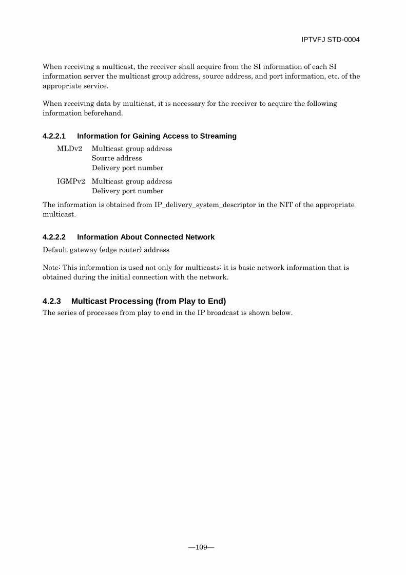
IPTVFJ STD-0004
—109—
When receiving a multicast, the receiver shall acquire from the SI information of each SI information server the multicast group address, source address, and port information, etc. of the appropriate service.
When receiving data by multicast, it is necessary for the receiver to acquire the following information beforehand.
4.2.2.1 Information for Gaining Access to Streaming MLDv2 Multicast group address Source address Delivery port number
IGMPv2 Multicast group address Delivery port number
The information is obtained from IP_delivery_system_descriptor in the NIT of the appropriate multicast.
4.2.2.2 Information About Connected Network Default gateway (edge router) address
Note: This information is used not only for multicasts: it is basic network information that is obtained during the initial connection with the network.
4.2.3 Multicast Processing (from Play to End) The series of processes from play to end in the IP broadcast is shown below.
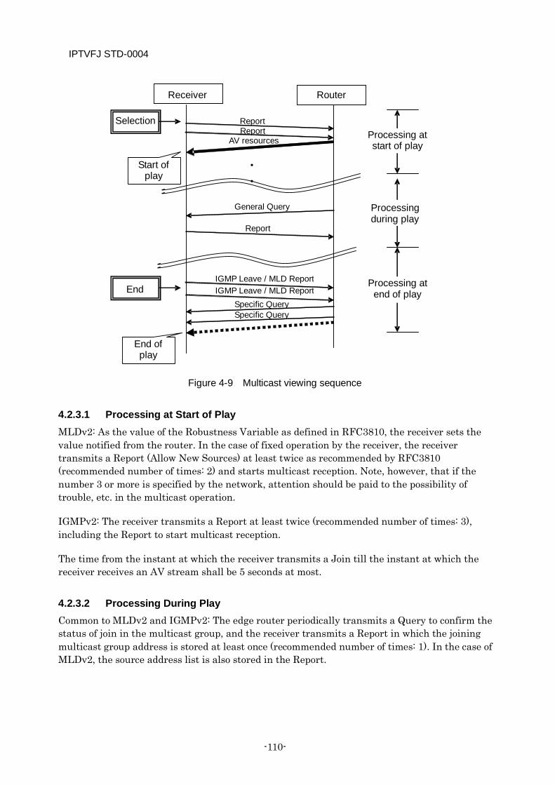
IPTVFJ STD-0004
-110-
Figure 4-9 Multicast viewing sequence
4.2.3.1 Processing at Start of Play MLDv2: As the value of the Robustness Variable as defined in RFC3810, the receiver sets the value notified from the router. In the case of fixed operation by the receiver, the receiver transmits a Report (Allow New Sources) at least twice as recommended by RFC3810 (recommended number of times: 2) and starts multicast reception. Note, however, that if the number 3 or more is specified by the network, attention should be paid to the possibility of trouble, etc. in the multicast operation.
IGMPv2: The receiver transmits a Report at least twice (recommended number of times: 3), including the Report to start multicast reception.
The time from the instant at which the receiver transmits a Join till the instant at which the receiver receives an AV stream shall be 5 seconds at most.
4.2.3.2 Processing During Play Common to MLDv2 and IGMPv2: The edge router periodically transmits a Query to confirm the status of join in the multicast group, and the receiver transmits a Report in which the joining multicast group address is stored at least once (recommended number of times: 1). In the case of MLDv2, the source address list is also stored in the Report.
Report
• •
Report
Specific Query Specific Query
General Query
Report
IGMP Leave / MLD Report IGMP Leave / MLD Report
End of play
Receiver Router
Selection
Start of play
AV resources Processing at start of play
Processing during play
End Processing at end of play
IPTVFJ STD-0004
—111—
4.2.3.3 Processing at End of Play MLDv2: As the value of the Robustness Variable defined in RFC3810, the receiver sets the value that is notified from the router. In the case of a fixed operation by the receiver, the receiver transmits an MLD Report to the router at least twice as recommended by RFC3810 (recommended number of times: 2) to end the multicast reception. Note, however, that if the number 3 or more is specified by the network, attention should be paid to the possibility of trouble, etc. in the multicast operation.
IGMPv2: The receiver transmits an IGMP Leave to the router at least once (recommended number of times: 2) to end the multicast reception.
4.2.4 Service Channel Selection Processing The service channel switching process in IP broadcasts is shown below.
Figure 4-10 Channel Switching Sequence
In the switching process, the end of viewing and the start of play are performed without interruption.
The Report for starting the play of the new AV stream after the switching may be transmitted before the old AV stream stops.
Note, however, that when the switching is done at high speed, more than one AV streams before the switching flows through the communication network. In this case, attention should be paid to the implementation of the receiver with reference to Chapter 3.
•
•
Specific Query Specific Query
Report (B)
IGMP Leave/MLD Report (A)
Report (B)
IGMP Leave/MLD Report (A)
Program B: AV resources
Receiver Router
Program A is being played
Program A: AV resources
Channel switching
A B
Program A stopped
Channel switching
processing
Program B is started
The AV resources of Program B may be transmitted before the transmission of those of
Program A is stopped.
IPTVFJ STD-0004
-112-
Concerning the time from the transmission of a Leave to the stopping of the stream, the following two cases are presupposed.
(1) In the case of a CDN in which the router stops the stream without issuing a Group-Specific Query (v4)/Source Specific Query (v6) in response to the Leave request from the receiver, sufficient time from transmission of the Leave to stopping of the stream shall be 300 ms.
(2) In the case of a CDN in which the router stops the stream after issuing a Group-Specific Query (v4)/Source Specific Query (v6) in response to the Leave request from the receiver and after confirming the status of other receivers, sufficient time from transmission of the Leave to stopping of the stream shall be 2.x seconds.
In the CDN scope, which of the above cases applies to the connected network is specified by the channel switching control flag in the CDN configuration information.
4.3 Streaming Quality In streaming distribution, there are concerns that a packet loss on the network or mistiming in asynchronous-type communication may disrupt the video/audio signals. From the standpoint of ensuring stable playback of the transmission server and the receiver for a long period of time, therefore, it is desirable that the following measures to improve the streaming quality should be implemented.
Here, the expression “stable playback of the receiver for a long period of time” means that in a steady state without traffic congestion the receiver receives TS streams without packet loss on a stable basis for a week or so.
4.3.1 FEC If a packet loss occurs on the network, it can disrupt video and audio signals. Therefore, suitable measures should be taken to prevent packet losses. Specifically, if a packet loss has occurred, it is necessary to recover it by using FEC.
Both the transmission server and the receiver are adaptable to FEC. When the same FEC is used in transmission and reception, it can be used by the server and the receiver. Providing the FEC function is optional.
When providing the receiver with FEC, RFC2733 and its extension shall, as a rule, be followed. In this operation specification, Pro-MPEG FEC Code of Practice #3 release 2 (“Pro-MPEG FEC”) is adopted. Note, however, that adopting the FEC system (“Pro-MPEG 1D FEC”), whereby both the transmitting side and receiving side process only the FEC packets in the vertical direction (see 4.3.1.5), is also allowed. When some other FEC system that is not currently defined in this operation specification is employed, as well as when the server operates the Pro-MPEG FEC two dimensionally (“Pro-MPEG 2D FEC”) whereby it processes FEC packets in the horizontal direction too (see 4.3.1.5), an FEC system which permits transmitting and receiving media packets and FEC packets using different ports so that even a receiver without the FEC function can receive those packets shall be employed. In this case, the receiver without the FEC function
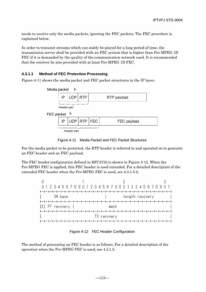
IPTVFJ STD-0004
—113—
needs to receive only the media packets, ignoring the FEC packets. The FEC procedure is explained below.
In order to transmit streams which can stably be played for a long period of time, the transmission server shall be provided with an FEC system that is higher than Pro-MPEG 1D FEC if it is demanded by the quality of the communication network used. It is recommended that the receiver be also provided with at least Pro-MPEG 1D FEC.
4.3.1.1 Method of FEC Protection Processing Figure 4-11 shows the media packet and FEC packet structures in the IP layer.
Figure 4-11 Media Packet and FEC Packet Structures
For the media packet to be protected, the RTP header is referred to and operated on to generate an FEC header and an FEC payload.
The FEC header configuration defined in RFC2733 is shown in Figure 4-12. When the Pro-MPEG FEC is applied, this FEC header is used extended. For a detailed description of the extended FEC header when the Pro-MPEG FEC is used, see 4.3.1.5.2.
Figure 4-12 FEC Header Configuration
The method of generating an FEC header is as follows. For a detailed description of the operation when the Pro-MPEG FEC is used, see 4.3.1.5.
FEC packet
Media packet
Header part
Header part
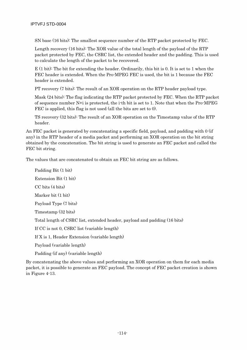
IPTVFJ STD-0004
-114-
SN base (16 bits): The smallest sequence number of the RTP packet protected by FEC.
Length recovery (16 bits): The XOR value of the total length of the payload of the RTP packet protected by FEC, the CSRC list, the extended header and the padding. This is used to calculate the length of the packet to be recovered.
E (1 bit): The bit for extending the header. Ordinarily, this bit is 0. It is set to 1 when the FEC header is extended. When the Pro-MPEG FEC is used, the bit is 1 because the FEC header is extended.
PT recovery (7 bits): The result of an XOR operation on the RTP header payload type.
Mask (24 bits): The flag indicating the RTP packet protected by FEC. When the RTP packet of sequence number N+i is protected, the i-th bit is set to 1. Note that when the Pro-MPEG FEC is applied, this flag is not used (all the bits are set to 0).
TS recovery (32 bits): The result of an XOR operation on the Timestamp value of the RTP header.
An FEC packet is generated by concatenating a specific field, payload, and padding with 0 (if any) in the RTP header of a media packet and performing an XOR operation on the bit string obtained by the concatenation. The bit string is used to generate an FEC packet and called the FEC bit string.
The values that are concatenated to obtain an FEC bit string are as follows.
Padding Bit (1 bit)
Extension Bit (1 bit)
CC bits (4 bits)
Marker bit (1 bit)
Payload Type (7 bits)
Timestamp (32 bits)
Total length of CSRC list, extended header, payload and padding (16 bits)
If CC is not 0, CSRC list (variable length)
If X is 1, Header Extension (variable length)
Payload (variable length)
Padding (if any) (variable length)
By concatenating the above values and performing an XOR operation on them for each media packet, it is possible to generate an FEC payload. The concept of FEC packet creation is shown in Figure 4-13.
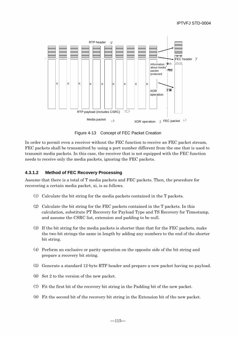
IPTVFJ STD-0004
—115—
Figure 4-13 Concept of FEC Packet Creation
In order to permit even a receiver without the FEC function to receive an FEC packet stream, FEC packets shall be transmitted by using a port number different from the one that is used to transmit media packets. In this case, the receiver that is not equipped with the FEC function needs to receive only the media packets, ignoring the FEC packets.
4.3.1.2 Method of FEC Recovery Processing Assume that there is a total of T media packets and FEC packets. Then, the procedure for recovering a certain media packet, xi, is as follows.
(1) Calculate the bit string for the media packets contained in the T packets.
(2) Calculate the bit string for the FEC packets contained in the T packets. In this calculation, substitute PT Recovery for Payload Type and TS Recovery for Timestamp, and assume the CSRC list, extension and padding to be null.
(3) If the bit string for the media packets is shorter than that for the FEC packets, make the two bit strings the same in length by adding any numbers to the end of the shorter bit string.
(4) Perform an exclusive or parity operation on the opposite side of the bit string and prepare a recovery bit string.
(5) Generate a standard 12-byte RTP header and prepare a new packet having no payload.
(6) Set 2 to the version of the new packet.
(7) Fit the first bit of the recovery bit string in the Padding bit of the new packet.
(8) Fit the second bit of the recovery bit string in the Extension bit of the new packet.
XOR operation
RTP header
Information about media packet protected
FEC header
XOR operation
RTP payload (includes CSRC)
Media packet FEC packet
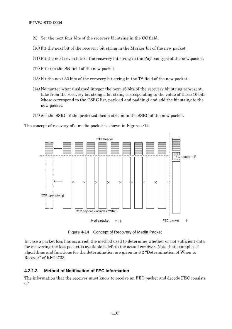
IPTVFJ STD-0004
-116-
(9) Set the next four bits of the recovery bit string in the CC field.
(10) Fit the next bit of the recovery bit string in the Marker bit of the new packet.
(11) Fit the next seven bits of the recovery bit string in the Payload type of the new packet.
(12) Fit xi in the SN field of the new packet.
(13) Fit the next 32 bits of the recovery bit string in the TS field of the new packet.
(14) No matter what unsigned integer the next 16 bits of the recovery bit string represent, take from the recovery bit string a bit string corresponding to the value of those 16 bits (these correspond to the CSRC list, payload and padding) and add the bit string to the new packet.
(15) Set the SSRC of the protected media stream in the SSRC of the new packet.
The concept of recovery of a media packet is shown in Figure 4-14.
Figure 4-14 Concept of Recovery of Media Packet
In case a packet loss has occurred, the method used to determine whether or not sufficient data for recovering the lost packet is available is left to the actual receiver. Note that examples of algorithms and functions for the determination are given in 8.2 “Determination of When to Recover” of RFC2733.
4.3.1.3 Method of Notification of FEC Information The information that the receiver must know to receive an FEC packet and decode FEC consists of:
FEC packet
RTP header
FEC header
XOR operation
RTP payload (includes CSRC)
Media packet
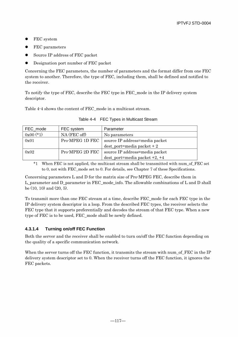
IPTVFJ STD-0004
—117—
FEC system
FEC parameters
Source IP address of FEC packet
Designation port number of FEC packet
Concerning the FEC parameters, the number of parameters and the format differ from one FEC system to another. Therefore, the type of FEC, including them, shall be defined and notified to the receiver.
To notify the type of FEC, describe the FEC type in FEC_mode in the IP delivery system descriptor.
Table 4-4 shows the content of FEC_mode in a multicast stream.
Table 4-4 FEC Types in Multicast Stream
FEC_mode FEC system Parameter 0x00 (*1) NA (FEC off) No parameters 0x01 Pro-MPEG 1D FEC source IP address=media packet
dest_port=media packet + 2 0x02 Pro-MPEG 2D FEC source IP address=media packet
dest_port=media packet +2, +4 *1 When FEC is not applied, the multicast stream shall be transmitted with num_of_FEC set
to 0, not with FEC_mode set to 0. For details, see Chapter 7 of these Specifications.
Concerning parameters L and D for the matrix size of Pro-MPEG FEC, describe them in L_parameter and D_parameter in FEC_mode_info. The allowable combinations of L and D shall be (10, 10) and (20, 5).
To transmit more than one FEC stream at a time, describe FEC_mode for each FEC type in the IP delivery system descriptor in a loop. From the described FEC types, the receiver selects the FEC type that it supports preferentially and decodes the stream of that FEC type. When a new type of FEC is to be used, FEC_mode shall be newly defined.
4.3.1.4 Turning on/off FEC Function Both the server and the receiver shall be enabled to turn on/off the FEC function depending on the quality of a specific communication network.
When the server turns off the FEC function, it transmits the stream with num_of_FEC in the IP delivery system descriptor set to 0. When the receiver turns off the FEC function, it ignores the FEC packets.
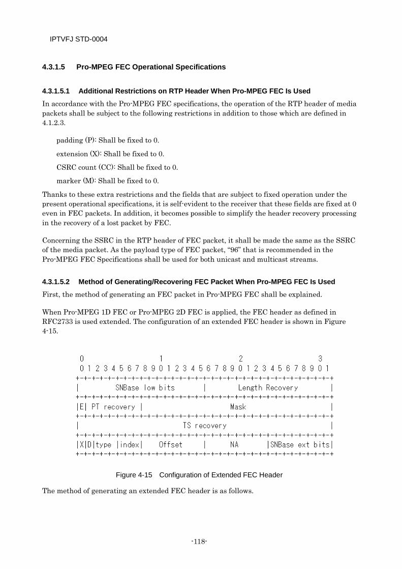
IPTVFJ STD-0004
-118-
4.3.1.5 Pro-MPEG FEC Operational Specifications
4.3.1.5.1 Additional Restrictions on RTP Header When Pro-MPEG FEC Is Used
In accordance with the Pro-MPEG FEC specifications, the operation of the RTP header of media packets shall be subject to the following restrictions in addition to those which are defined in 4.1.2.3.
padding (P): Shall be fixed to 0.
extension (X): Shall be fixed to 0.
CSRC count (CC): Shall be fixed to 0.
marker (M): Shall be fixed to 0.
Thanks to these extra restrictions and the fields that are subject to fixed operation under the present operational specifications, it is self-evident to the receiver that these fields are fixed at 0 even in FEC packets. In addition, it becomes possible to simplify the header recovery processing in the recovery of a lost packet by FEC.
Concerning the SSRC in the RTP header of FEC packet, it shall be made the same as the SSRC of the media packet. As the payload type of FEC packet, “96” that is recommended in the Pro-MPEG FEC Specifications shall be used for both unicast and multicast streams.
4.3.1.5.2 Method of Generating/Recovering FEC Packet When Pro-MPEG FEC Is Used
First, the method of generating an FEC packet in Pro-MPEG FEC shall be explained.
When Pro-MPEG 1D FEC or Pro-MPEG 2D FEC is applied, the FEC header as defined in RFC2733 is used extended. The configuration of an extended FEC header is shown in Figure 4-15.
Figure 4-15 Configuration of Extended FEC Header
The method of generating an extended FEC header is as follows.

IPTVFJ STD-0004
—119—
SNBase low bits (16 bits): The lower 16 bits of the smallest sequence number of the RTP packet protected by FEC. When the sequence number falls within 16 bits, describe it directly.
Length recovery (16 bits): The XOR value of the total length of payload, CSRC list, extended header and padding of the RTP packet protected by FEC. This is used to calculate the length of the packet to be recovered.
E (1 bit): The bit for header extension. Set this bit to 1 to extend the FEC header.
PT recovery (7 bits): The result of an XOR operation on the payload type of the RTP header.
Mask (24 bits): Set all these bits to 0. (In this case, the NA field is used.)
TS recovery (32 bits): The result of an XOR operation on the Timestamp value of the RTP header.
X (1 bit): Set this bit to 0. (It is reserved for header extension in the future.)
D (1 bit): Set this bit to 0 for FEC in vertical direction (column) and 1 for FEC in horizontal direction (row).
Type (3 bits): Set these bits to 0 since XOR operations are performed (XOR = 0, hamming = 1, Reed-Solomon = 2).
Index (3 bits): Set these bits to 0 for XOR operation (used when performing more complicated FEC processing).
Offset (8 bits): Indicates the period of media packets — L for vertical (column) FEC and 1 for horizontal (row) FEC.
NA (8 bits): Indicates the number of media packets protected—D for vertical (column) FEC and L for horizontal (row) FEC.
SNBase ext bits (8 bits): Used when 16 bits are insufficient for the sequence number. In the case of MPEG2-TS, set these bits to 0 since 16 bits are sufficient for the sequence number.
The operations performed for Pro-MPEG FEC (L × D = 10 × 10) are shown in Fig. Figure 4-16. In the case of Pro-MPEG 1D FEC, the operation is performed on the FEC headers and FEC payloads in the vertical direction of the matrix to generate 10 FEC packets in the vertical direction (column). In the case of Pro-MPEG 2D FEC, the operation is also performed in the horizontal direction to generate 10 FEC packets in the horizontal direction (row).
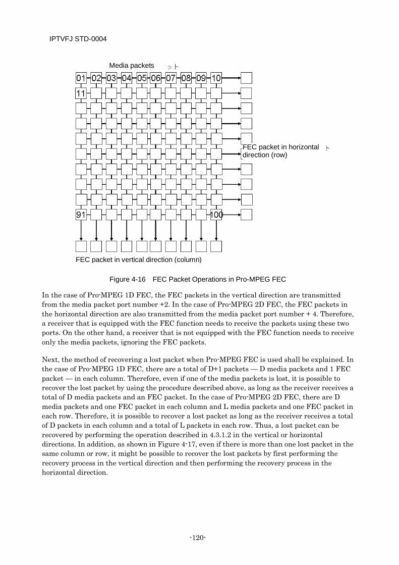
IPTVFJ STD-0004
-120-
Figure 4-16 FEC Packet Operations in Pro-MPEG FEC
In the case of Pro-MPEG 1D FEC, the FEC packets in the vertical direction are transmitted from the media packet port number +2. In the case of Pro-MPEG 2D FEC, the FEC packets in the horizontal direction are also transmitted from the media packet port number + 4. Therefore, a receiver that is equipped with the FEC function needs to receive the packets using these two ports. On the other hand, a receiver that is not equipped with the FEC function needs to receive only the media packets, ignoring the FEC packets.
Next, the method of recovering a lost packet when Pro-MPEG FEC is used shall be explained. In the case of Pro-MPEG 1D FEC, there are a total of D+1 packets — D media packets and 1 FEC packet — in each column. Therefore, even if one of the media packets is lost, it is possible to recover the lost packet by using the procedure described above, as long as the receiver receives a total of D media packets and an FEC packet. In the case of Pro-MPEG 2D FEC, there are D media packets and one FEC packet in each column and L media packets and one FEC packet in each row. Therefore, it is possible to recover a lost packet as long as the receiver receives a total of D packets in each column and a total of L packets in each row. Thus, a lost packet can be recovered by performing the operation described in 4.3.1.2 in the vertical or horizontal directions. In addition, as shown in Figure 4-17, even if there is more than one lost packet in the same column or row, it might be possible to recover the lost packets by first performing the recovery process in the vertical direction and then performing the recovery process in the horizontal direction.
FEC packet in vertical direction (column)
Media packets
FEC packet in horizontal direction (row)
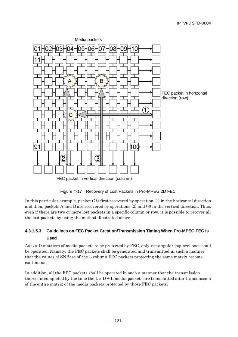
IPTVFJ STD-0004
—121—
Figure 4-17 Recovery of Lost Packets in Pro-MPEG 2D FEC
In this particular example, packet C is first recovered by operation (1) in the horizontal direction and then, packets A and B are recovered by operations (2) and (3) in the vertical direction. Thus, even if there are two or more lost packets in a specific column or row, it is possible to recover all the lost packets by using the method illustrated above.
4.3.1.5.3 Guidelines on FEC Packet Creation/Transmission Timing When Pro-MPEG FEC Is Used
As L × D matrices of media packets to be protected by FEC, only rectangular (square) ones shall be operated. Namely, the FEC packets shall be generated and transmitted in such a manner that the values of SNBase of the L column FEC packets protecting the same matrix become continuous.
In addition, all the FEC packets shall be operated in such a manner that the transmission thereof is completed by the time the L × D + L media packets are transmitted after transmission of the entire matrix of the media packets protected by those FEC packets.
FEC packet in horizontal direction (row)
Media packets
FEC packet in vertical direction (column)
IPTVFJ STD-0004
-122-
When the value of SSRC in the RTP header of a media packet is changed as a result of channel source switching, etc., the creation of FEC packets shall be limited to those FEC packets which can be generated from the SSRC before it is changed, rather than mix media packets having a different SSRC in the same matrix. FEC packets after the change of SSRC shall be generated from a new matrix of media packets.
4.3.2 Clock Synchronization Unlike RF transmission using radio waves, IP transmission is an asynchronous-type communication, in which explicit transfer of the clock information is difficult. However, in order to ensure stable play for a long period of time, the clock synchronization mechanism from the transmitting side to the receiving side is important.
Since IP transmissions demand a best-effort transmission system, a robust synchronization mechanism which takes into account various types of disturbances, such as packet loss, jittering and burst, is required.
In these Specifications, from the standpoint of performance/accuracy of synchronization and compatibility with other relevant standards, etc., the timestamped TS (TTS) as defined in ARIB STD-B24 shall be introduced. In TTS, a 4-byte, 27-MHz-based timestamp is prefixed to the beginning of each TS packet (188 bytes in length).
In IP broadcasting services, TTS shall be used, and a 27-MHz timestamp added to each TS packet shall be synchronized with the PCR of the appropriate TS. The receiver, which is equipped with the TTS decoding function, stores the TTS packet it receives in the FIFO memory to buffer it and compares the local counter value with the timestamp value of the TTS packet in the FIFO memory to perform the gating process to output the TTS packet. In so doing, it is possible to implement clock synchronization by subjecting the local counter to subordinate synchronization with the clock at the transmitting side. Although the method of subordinate synchronization is left to the actual receiver, several methods are presupposed, including the method that uses the transmitter-side 27-MHz information provided by the TTS timestamp and the method that uses the remaining capacity of the FIFO memory.
The process of clock synchronization by TTS between the transmitter and the receiver is shown in Figure 4-18.

IPTVFJ STD-0004
—123—
Figure 4-18 System Configuration Relating to Clock Synchronization
Audio decoding
Transmitting side Real-time system
Multiplexing Generating TTS
Addition of 4-byte
timestamp FEC
(optional) IP
processing UDP
IP processi
ng UDP
FEC (optional)
Decoding TTS
Video decoding
Receiving side
Network
IPTVFJ STD-0004
-124-
Chapter 5 Video Content
5.1 Encoding of Information Sources
5.1.1 Video
5.1.1.1 Specifications on Input Signals
<Specifications on Video Format>
The specifications on <video format> in 4.1.1 “Provisions Regarding Input Signals” of ARIB TR-B14 Volume 7 shall be followed.
Note, however, that as defined below, the 480p (525p) video format shall not be operated.
In the explanations given in the following paragraphs, the following descriptions indicate the same video format.
525 scanning lines (number of effective scanning lines: 483) and sequential scanning
vertical_size_value=480 and progressive_sequence=1
480p
525p
<Aspect Ratio>
In the case of MPEG2, the specifications on <aspect ratio> in 4.1.1 “Provisions Regarding Input Signals” of ARIB TR-B14 Volume 7 shall be followed. Note, however, that the video signals (vertical_size_value = 480 and progressive_sequence = 1) that are subject to 525 scanning lines (number of effective scanning lines: 483) and sequential scanning shall not be operated.
In the case of H.264/MPEG4 AVC, [Appendix A] A.14 “Pan-scan rectangle SEI” shall be followed.
<Colorimetry>
The specifications on <colorimetry> in 4.1.1 “Provisions Regarding Input Signals” of ARIB TR-B14 Volume 7 shall be followed.
<Encode Area>
The specifications on <encode area> in 4.1.1 “Provisions Regarding Input Signals” of ARIB TR-B14 Part 7 shall be followed.
<GOP Structure>
The GOP length shall, as a rule, be 500 ms and shall not exceed 1 s.

IPTVFJ STD-0004
—125—
5.1.1.2 Details of MPEG-2 (Video) Operation
<Moving Picture Formats>
720×480I MP@ML
480×480I MP@ML
<Encoding System>
The specifications on <encoding system> in 4.1.2 “Detailed Information on the Operation of MPEG-2 (Video)” of ARIB TR-B14 Volume 7 shall be followed.
<Restrictions on Encoding Parameters>
The <restrictions on encoding parameters> in 4.1.2 “Detailed Information on the Operation of MPEG-2 (Video)” of ARIB TR-B14 Volume 7 shall be followed; provided, however, that the following formats shall not be operated.
Format (480p) with vertical_size_value = 480 and progressive_sequence = 1
MP@LL moving pictures and still pictures (MPEG still pictures)
In addition, reference shall not be made to the description relating to the partial reception layer.
Table 5-1 Restrictions on Encoding Parameters
Parameter values of sequence_header Parameter value
of sequence_ extension
Parameter values of sequence_display
_extension
vertical_ size_value
horizontal_ size_value
aspect_ ratio_
information
progressive _sequence
display_ vertical_
size
display_ horizontal
_size
1080 1920 2 0 1080 1440 1440 1080
720 1280 2 1 720 960 480 720 2 0 480 540 480 720 3 0 360 720
<Change of Encoding Parameters>
It is desirable to follow the Appendix “Operating Guidelines” in ARIB STD-B32.
<Range of Video Encoding Rate>
For the time being, the range of video encoding rate shall be as shown below. However, each individual station shall decide the bit rate in actual transmission with due consideration given to the picture quality.
MP@ML : 1.5~10 Mbps
IPTVFJ STD-0004
-126-
5.1.1.3 Details of H264/MPEG-4 AVC Video Operation The specifications defined in [Appendix A] to this document shall be followed.
<Moving Picture Formats>
1920×1080I [email protected]
1440×1080I [email protected]
1280×720P [email protected]
720×480I [email protected]/3.1/3.2
<Range of Video Encoding Rate>
The range of video encoding rate shall be as shown below. However, each individual station shall decide the bit rate in actual transmission with due consideration given to the picture quality
[email protected] : 3~15 Mbps [email protected]/3.1/3.2 : 0.5~8 Mbps
5.1.1.4 Combinations of Video/Audio Encoding Systems The video/audio encoding systems shall be operated in either of the following combinations.
Combination 1 (SD service) Combination 2 (HD/SD service) Video encoding MPEG2 Video H264/MPEG-4 AVC Audio encoding MPEG2-AAC
MPEG1-L2 MPEG2-AAC
5.1.2 Audio
5.1.2.1 MPEG1 (Audio)
5.1.2.1.1 Specifications on MPEG1 (Audio) Input Signals
<Sampling Rate>
(1) In each service, the same sampling rate shall always be used. This is to prevent the occurrence of a mute part within the same broadcasting station service when the D/A converter clock is changed.
(2) The sampling rate shall be 32 kHz or 48 kHz.
<Audio Modes>
The audio modes shall be single channel, dual channel and stereo.

IPTVFJ STD-0004
—127—
<Emphasis>
Emphasis shall not be used.
5.1.2.1.2 Details of MPEG1 (Audio) Operation
The specifications defined in Explanation 1.2 “Main system parameters” of ARIB STD-B1 shall be followed.
CRC shall be operated in such a manner that the receiver can use it.
Layer 2 shall be used for encoding.
5.1.2.1.3 Range of Audio Encoding Rate
As the bit rates of audio encoding, the following values shall be applied.
5.1.2.2 MPEG2 (Audio)
5.1.2.2.1 Specifications on MPEG2 (Audio) Input Signals
<Sampling Rate>
(1) In each service, the same sampling rate shall always be used. This is to prevent the occurrence of a mute part within the same broadcasting station service when the D/A converter clock is changed.
(2) The sampling rate shall be 48 kHz.
<Audio Mode>
The audio modes in 1 ADTS shall be in accordance with the recommended audio modes defined in 5.1 “Input Audio Format” of ARIB STD-B32 Part 2.
<Downmix Coefficient>
The specifications defined in 5.2 “Audio Coding System” of ARIB STD-B32 Part 2 and 6.2.1 “Audio Decoding Process” of ARIB STD-B21 shall be followed.
There are cases in which a downmix coefficient is not transmitted. In such cases, the default value shall be used for decoding. When a downmix coefficient other than the default value is used, it must be transmitted.
<Audio Level>
The audio level shall be in accordance with 4.2.1 “Provisions Regarding Input Signals” of ARIB TR-B14 Volume 7.
Standard stereo : 64 kbps, 96 kbps, 128 kbps, 192 kbps, 224 kbps, 256 kbps, 384 kbps
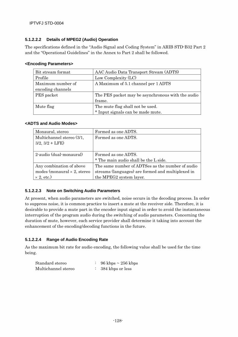
IPTVFJ STD-0004
-128-
5.1.2.2.2 Details of MPEG2 (Audio) Operation
The specifications defined in the “Audio Signal and Coding System” in ARIB STD-B32 Part 2 and the “Operational Guidelines” in the Annex to Part 2 shall be followed.
<Encoding Parameters>
Bit stream format AAC Audio Data Transport Stream (ADTS) Profile Low Complexity (LC) Maximum number of encoding channels
A Maximum of 5.1 channel per 1 ADTS
PES packet The PES packet may be asynchronous with the audio frame.
Mute flag The mute flag shall not be used. * Input signals can be made mute.
<ADTS and Audio Modes>
Monaural, stereo Formed as one ADTS. Multichannel stereo (3/1, 3/2, 3/2 + LFE)
Formed as one ADTS.
2-audio (dual-monaural) Formed as one ADTS. * The main audio shall be the L side.
Any combination of above modes (monaural × 2, stereo × 2, etc.)
The same number of ADTSes as the number of audio streams (languages) are formed and multiplexed in the MPEG2 system layer.
5.1.2.2.3 Note on Switching Audio Parameters
At present, when audio parameters are switched, noise occurs in the decoding process. In order to suppress noise, it is common practice to insert a mute at the receiver side. Therefore, it is desirable to provide a mute part in the encoder input signal in order to avoid the instantaneous interruption of the program audio during the switching of audio parameters. Concerning the duration of mute, however, each service provider shall determine it taking into account the enhancement of the encoding/decoding functions in the future.
5.1.2.2.4 Range of Audio Encoding Rate
As the maximum bit rate for audio encoding, the following value shall be used for the time being.
Standard stereo : 96 kbps ~ 256 kbps Multichannel stereo : 384 kbps or less
IPTVFJ STD-0004
—129—
5.1.3 Caption
5.1.3.1 Scope and Definition of Service The caption service for streams received at the receiver refers to the following.
Caption: The caption service synchronized with the main video/audio (e.g., translated caption).
Concerning the specifications on captions, reference is made to the caption specifications that are included in Section 2, Chapter 4 “Operation of Caption and Superimpose Encoding” of Volume 3 “Specifications for Data Broadcasting Operations” in ARIB TR-B14 “Operational Specifications on Terrestrial Digital Television Broadcasting.” Note, however, that the roll-up mode, caption outscreen display function and character superimposition are not operated. Details of the caption service are given below.
5.1.3.2 Configuration and Transmission Operation Of the specifications defined in 4.2 “Composition and Transmission Operation” Volume 3, Section 2 of ARIB TR-B14, the specifications on captions shall be referred to.
Concerning the following items, however, the following specifications shall apply.
4.2.1 (3) Number of ES
(4) Multi-view, the multi-view of ES shall not be operated.
(5) Temporary service, the temporary service of ES shall not be operated.
4.2.8.1 In the operation of component tags, the transmission of partial reception layer shall not be operated.
4.2.8.4 In the operation of descriptors, “Data Contents Descriptor” shall not be operated.
4.2.8.7 Data Contents Descriptor shall not be operated.
5.1.3.3 Video Resolution and Caption Display Format Refer to the specifications defined in 4.3 “Visual Pixel Size and Display Format of Caption/Superimpose” of ARIB TR-B14 Volume 3, Section 2.
5.1.3.4 Characters Used in Captions Refer to the specifications defined in 4.4 “Characters Used in Caption/Superimpose” of ARIB TR-B14 Volume 3, Section 2.
5.1.3.5 Control Codes Used in Captions Refer to the specifications on captions in 4.5 “Control Codes Used in Caption/Superimpose” of ARIB TR-B14 Volume 3, Section 2.
IPTVFJ STD-0004
-130-
5.1.3.6 Operation of DRCS Refer to the specifications on captions in 4.6 “Operation of the DRCS” of ARIB TR-B14 Volume 3, Section 2.
5.1.3.7 Operation of Initialization Action Refer to the specifications on captions in 4.7 “Operation of Initialization” of ARIB TR-B14 Volume 3, Section 2.
5.1.3.8 Monomedia Used in Captions Refer to the specifications on captions in 4.8 “Mono-media Used in Caption and Superimpose” of ARIB TR-B14 Volume 3, Section 2.
5.1.3.9 Desirable Receiver Operations Refer to the specifications on captions in 4.9 “Expected Performance of the Receiver Units” of ARIB TR-B14 Volume 3, Section 2.
5.1.3.10 Roll-up Mode The roll-up mode defined in 4.10 “Roll-up Mode(Optional)” of ARIB TR-B14 Volume 3, Section 2 shall not be operated.
Note, however, that the receiver shall not malfunction even if it receives data indicating the roll-up mode.
5.1.3.11 Caption Outscreen The caption out-screen defined in 4.11 “Caption Outscreen Display Function(Optional)” of ARIB TR-B14 Volume 3, Section 2 shall not be operated.
5.2 Multiplexing
5.2.1 Multiplexing within Service
5.2.1.1 Restrictions on Change of Encoding Parameters During operation of encoding parameters, the following restrictions shall be followed.
In the video ES within a service, the video encoding system shall, as a rule, be operated in a fixed format. For example, in a specific event, etc., the video encoding system must not carelessly be changed (H264 MPEG2 or MPEG2 H264). If it is absolutely necessary to change the current video encoding system because of the introduction of HDTV in the service, etc., a service suspension section must be provided. For details about the suspension section, see 5.3.4.
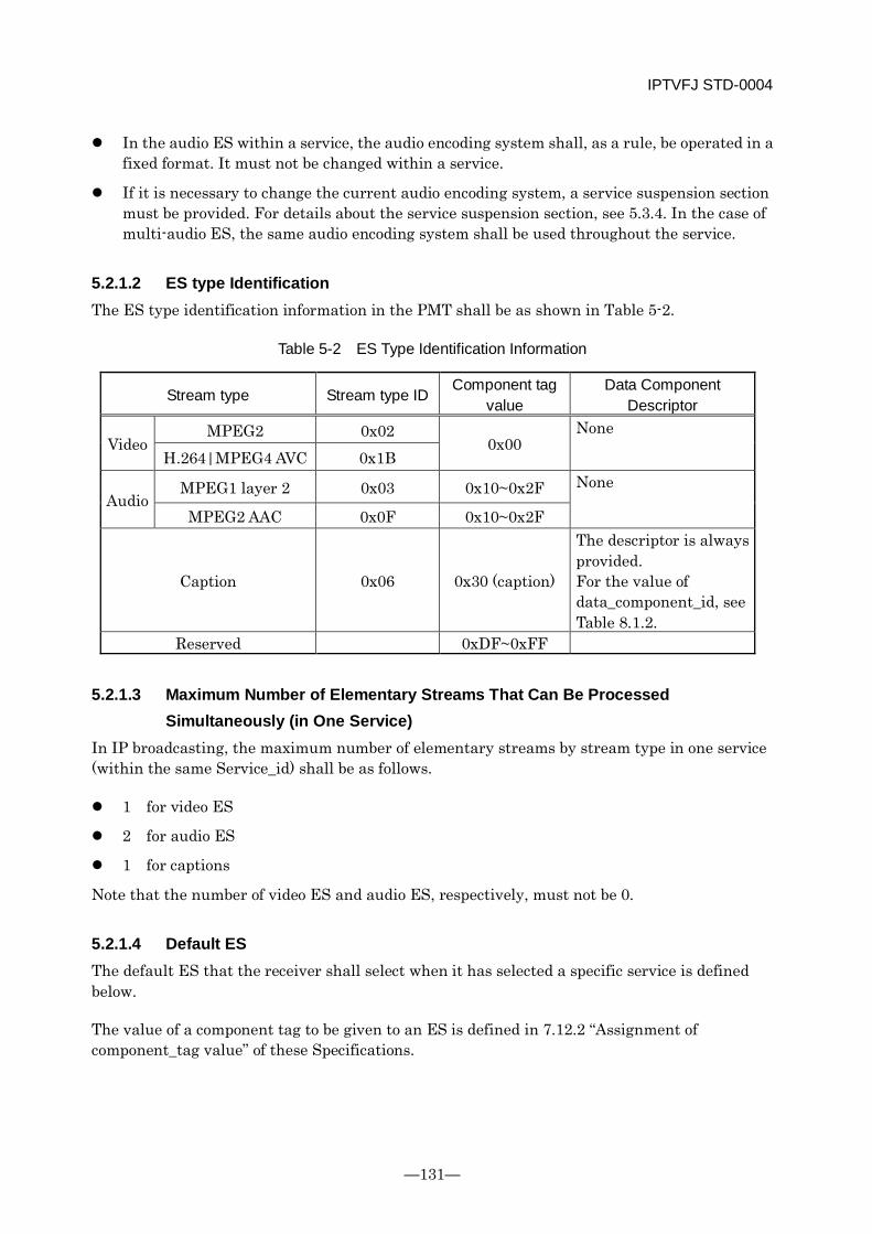
IPTVFJ STD-0004
—131—
In the audio ES within a service, the audio encoding system shall, as a rule, be operated in a fixed format. It must not be changed within a service.
If it is necessary to change the current audio encoding system, a service suspension section must be provided. For details about the service suspension section, see 5.3.4. In the case of multi-audio ES, the same audio encoding system shall be used throughout the service.
5.2.1.2 ES type Identification The ES type identification information in the PMT shall be as shown in Table 5-2.
Table 5-2 ES Type Identification Information
Stream type Stream type ID Component tag
value Data Component
Descriptor
Video MPEG2 0x02
0x00 None
H.264|MPEG4 AVC 0x1B
Audio MPEG1 layer 2 0x03 0x10~0x2F None
MPEG2 AAC 0x0F 0x10~0x2F
Caption 0x06 0x30 (caption)
The descriptor is always provided. For the value of data_component_id, see Table 8.1.2.
Reserved 0xDF~0xFF
5.2.1.3 Maximum Number of Elementary Streams That Can Be Processed Simultaneously (in One Service)
In IP broadcasting, the maximum number of elementary streams by stream type in one service (within the same Service_id) shall be as follows.
1 for video ES
2 for audio ES
1 for captions
Note that the number of video ES and audio ES, respectively, must not be 0.
5.2.1.4 Default ES The default ES that the receiver shall select when it has selected a specific service is defined below.
The value of a component tag to be given to an ES is defined in 7.12.2 “Assignment of component_tag value” of these Specifications.

IPTVFJ STD-0004
-132-
According to 7.12.2, the default ES by stream type can be defined based on the component tag value that is described in the appropriate Stream Identification Descriptor in the PMT, as follows.
Video stream: The ES whose component tag value is 0x00. Audio stream: The ES whose component tag value is 0x10 Caption stream: The ES whose component tag value is 0x30
5.2.2 Detailed Operation of MPEG-2 (Systems)
5.2.2.1 Definition of Services The services by media type shall be defined as follows.
Digital TV service: This is a service that contains one or more video streams and one or more audio streams in a broadcast and that permits even a receiver not equipped with the data broadcast receiving function to always enjoy the service programs on a stable basis.
Digital audio service: This service shall not be operated.
Data broadcast service: This service shall not be operated.
Promotion video service: This is a service that is transmitted non-scrambled (free program).
5.2.2.2 Synchronization of Video, Audio and Captions The receiver side synchronizes video, audio and caption signals using the PTS or the DTS or both. Therefore, the transmitting side shall control the synchronization of video, audio and caption signals so that the receiver can function properly.
5.2.2.3 Multiplexing of SI The maximum bit rate assigned to SI that is multiplexed in ordinary TS shall be as follows.
SI: Max 1 Mbps for the entire SI (average bit rate per second; see 7.9.2 for details).
5.2.2.4 Operation of PAT and NIT (1) In the PAT, only one program_number and only one program_map_PID shall be
inserted. (2) The sequencial order of TS and services described in the NIT has no meaning: it has
nothing to do with the receiver operation.
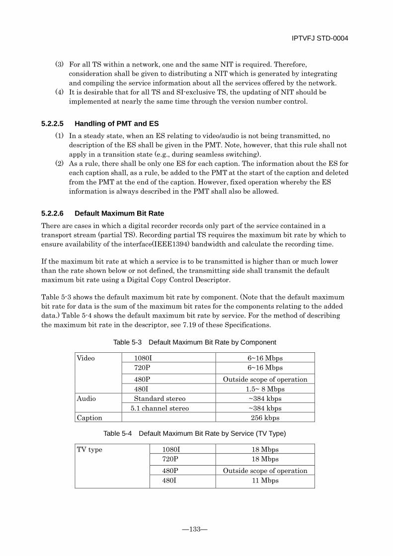
IPTVFJ STD-0004
—133—
(3) For all TS within a network, one and the same NIT is required. Therefore, consideration shall be given to distributing a NIT which is generated by integrating and compiling the service information about all the services offered by the network.
(4) It is desirable that for all TS and SI-exclusive TS, the updating of NIT should be implemented at nearly the same time through the version number control.
5.2.2.5 Handling of PMT and ES (1) In a steady state, when an ES relating to video/audio is not being transmitted, no
description of the ES shall be given in the PMT. Note, however, that this rule shall not apply in a transition state (e.g., during seamless switching).
(2) As a rule, there shall be only one ES for each caption. The information about the ES for each caption shall, as a rule, be added to the PMT at the start of the caption and deleted from the PMT at the end of the caption. However, fixed operation whereby the ES information is always described in the PMT shall also be allowed.
5.2.2.6 Default Maximum Bit Rate There are cases in which a digital recorder records only part of the service contained in a transport stream (partial TS). Recording partial TS requires the maximum bit rate by which to ensure availability of the interface(IEEE1394) bandwidth and calculate the recording time.
If the maximum bit rate at which a service is to be transmitted is higher than or much lower than the rate shown below or not defined, the transmitting side shall transmit the default maximum bit rate using a Digital Copy Control Descriptor.
Table 5-3 shows the default maximum bit rate by component. (Note that the default maximum bit rate for data is the sum of the maximum bit rates for the components relating to the added data.) Table 5-4 shows the default maximum bit rate by service. For the method of describing the maximum bit rate in the descriptor, see 7.19 of these Specifications.
Table 5-3 Default Maximum Bit Rate by Component
Video 1080I 6~16 Mbps 720P 6~16 Mbps 480P Outside scope of operation 480I 1.5~ 8 Mbps
Audio Standard stereo ~384 kbps 5.1 channel stereo ~384 kbps
Caption 256 kbps
Table 5-4 Default Maximum Bit Rate by Service (TV Type)
TV type 1080I 18 Mbps 720P 18 Mbps 480P Outside scope of operation 480I 11 Mbps
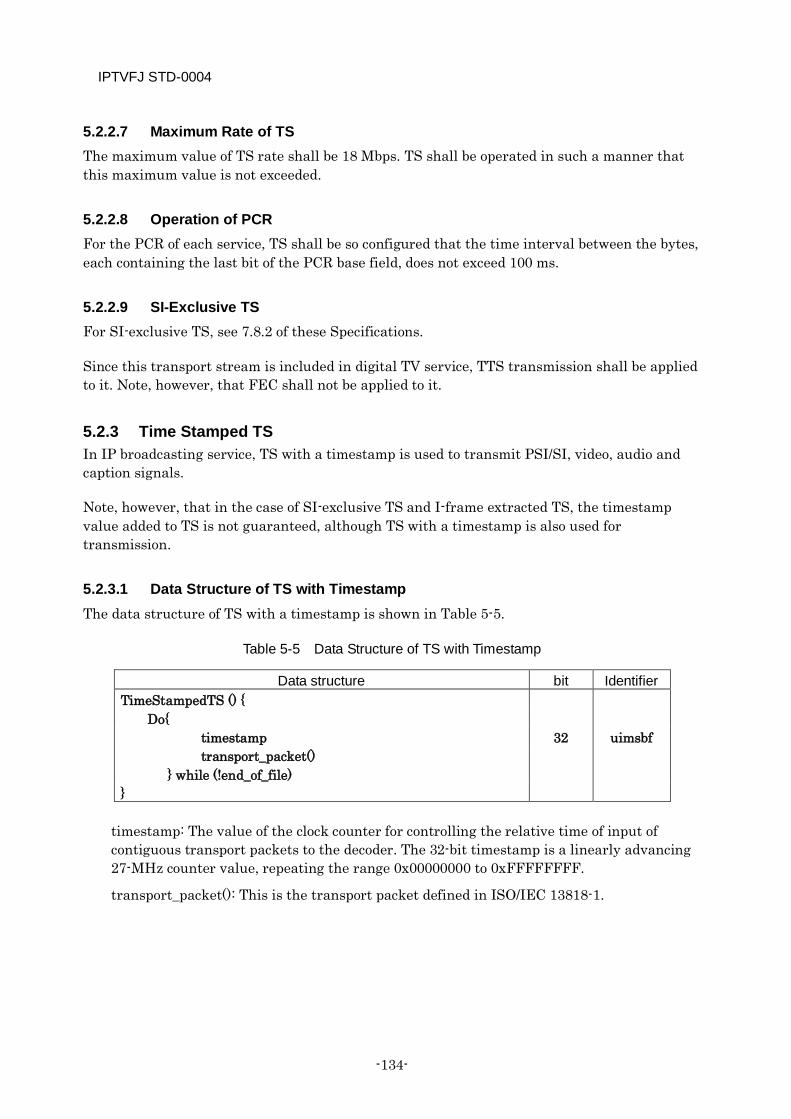
IPTVFJ STD-0004
-134-
5.2.2.7 Maximum Rate of TS The maximum value of TS rate shall be 18 Mbps. TS shall be operated in such a manner that this maximum value is not exceeded.
5.2.2.8 Operation of PCR For the PCR of each service, TS shall be so configured that the time interval between the bytes, each containing the last bit of the PCR base field, does not exceed 100 ms.
5.2.2.9 SI-Exclusive TS For SI-exclusive TS, see 7.8.2 of these Specifications.
Since this transport stream is included in digital TV service, TTS transmission shall be applied to it. Note, however, that FEC shall not be applied to it.
5.2.3 Time Stamped TS In IP broadcasting service, TS with a timestamp is used to transmit PSI/SI, video, audio and caption signals.
Note, however, that in the case of SI-exclusive TS and I-frame extracted TS, the timestamp value added to TS is not guaranteed, although TS with a timestamp is also used for transmission.
5.2.3.1 Data Structure of TS with Timestamp The data structure of TS with a timestamp is shown in Table 5-5.
Table 5-5 Data Structure of TS with Timestamp
Data structure bit Identifier TimeStampedTS () {
Do{ timestamp 32 uimsbf transport_packet() } while (!end_of_file) }
timestamp: The value of the clock counter for controlling the relative time of input of contiguous transport packets to the decoder. The 32-bit timestamp is a linearly advancing 27-MHz counter value, repeating the range 0x00000000 to 0xFFFFFFFF.
transport_packet(): This is the transport packet defined in ISO/IEC 13818-1.
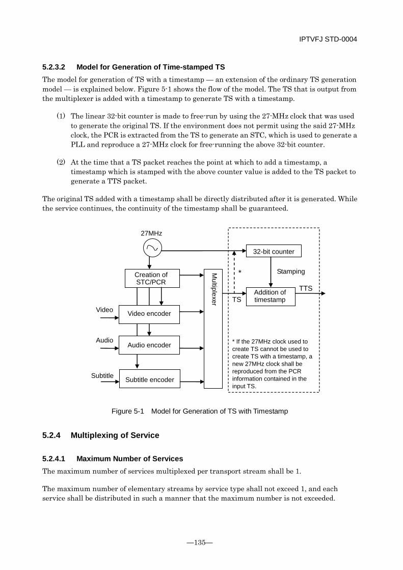
IPTVFJ STD-0004
—135—
5.2.3.2 Model for Generation of Time-stamped TS The model for generation of TS with a timestamp — an extension of the ordinary TS generation model — is explained below. Figure 5-1 shows the flow of the model. The TS that is output from the multiplexer is added with a timestamp to generate TS with a timestamp.
(1) The linear 32-bit counter is made to free-run by using the 27-MHz clock that was used to generate the original TS. If the environment does not permit using the said 27-MHz clock, the PCR is extracted from the TS to generate an STC, which is used to generate a PLL and reproduce a 27-MHz clock for free-running the above 32-bit counter.
(2) At the time that a TS packet reaches the point at which to add a timestamp, a timestamp which is stamped with the above counter value is added to the TS packet to generate a TTS packet.
The original TS added with a timestamp shall be directly distributed after it is generated. While the service continues, the continuity of the timestamp shall be guaranteed.
Audio encoder
Creation of STC/PCR
Multiplexer
Video encoder
TS TTS
Video
Audio
27MHz
32-bit counter
Subtitle encoder Subtitle
* If the 27MHz clock used to create TS cannot be used to create TS with a timestamp, a new 27MHz clock shall be reproduced from the PCR information contained in the input TS.
*
Addition of timestamp
Stamping
Figure 5-1 Model for Generation of TS with Timestamp
5.2.4 Multiplexing of Service
5.2.4.1 Maximum Number of Services The maximum number of services multiplexed per transport stream shall be 1.
The maximum number of elementary streams by service type shall not exceed 1, and each service shall be distributed in such a manner that the maximum number is not exceeded.
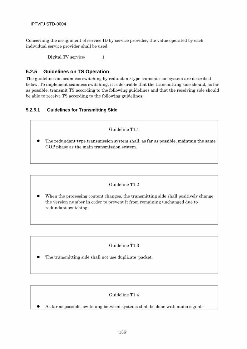
IPTVFJ STD-0004
-136-
Concerning the assignment of service ID by service provider, the value operated by each individual service provider shall be used.
Digital TV service: 1
5.2.5 Guidelines on TS Operation The guidelines on seamless switching by redundant-type transmission system are described below. To implement seamless switching, it is desirable that the transmitting side should, as far as possible, transmit TS according to the following guidelines and that the receiving side should be able to receive TS according to the following guidelines.
5.2.5.1 Guidelines for Transmitting Side
Guideline T1.1
The redundant-type transmission system shall, as far as possible, maintain the same
GOP phase as the main transmission system.
Guideline T1.2
When the processing content changes, the transmitting side shall positively change
the version number in order to prevent it from remaining unchanged due to redundant switching.
Guideline T1.3
The transmitting side shall not use duplicate_packet.
Guideline T1.4
As far as possible, switching between systems shall be done with audio signals
IPTVFJ STD-0004
—137—
muted.
5.2.5.2 Guidelines for Receiving Side
Guideline R1.1
If no errors has been detected in the transmission system and
transport_error_indicator is not set, the video or audio should not be muted even when a discontinuity has been found in the continuity index(continyity_counter).
Guideline R1.2
Even when the version number changes, the receiving side shall not perform
unnecessary processing as long as the content of decoding process remains the same.
Guideline R1.3
Even when the PTS differential of audio PES packets jitters by 0 to about two times
before and after switching, the receiving side shall, as far as possible, avoid muting the audio signals. Instead, it shall render the problem harmless by controlling the playback clock pitch, performing skipping and repeating processing, etc.
Guideline R1.4
The receiving side shall discard incomplete sections, such as those which are
discontinued midstream or which start from the middle. Instead, it shall use the next complete section that it receives.

IPTVFJ STD-0004
-138-
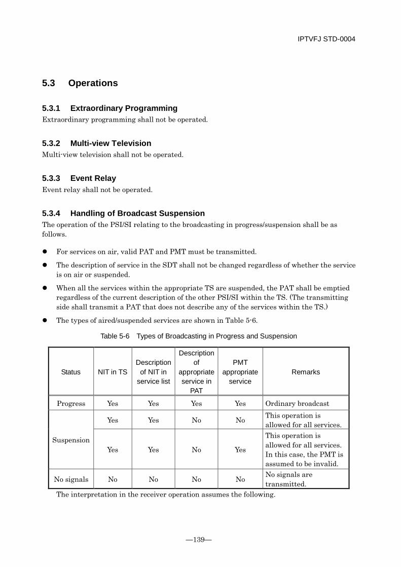
IPTVFJ STD-0004
—139—
5.3 Operations
5.3.1 Extraordinary Programming Extraordinary programming shall not be operated.
5.3.2 Multi-view Television Multi-view television shall not be operated.
5.3.3 Event Relay Event relay shall not be operated.
5.3.4 Handling of Broadcast Suspension The operation of the PSI/SI relating to the broadcasting in progress/suspension shall be as follows.
For services on air, valid PAT and PMT must be transmitted.
The description of service in the SDT shall not be changed regardless of whether the service is on air or suspended.
When all the services within the appropriate TS are suspended, the PAT shall be emptied regardless of the current description of the other PSI/SI within the TS. (The transmitting side shall transmit a PAT that does not describe any of the services within the TS.)
The types of aired/suspended services are shown in Table 5-6.
Table 5-6 Types of Broadcasting in Progress and Suspension
Status NIT in TS Description
of NIT in service list
Description of
appropriate service in
PAT
PMT appropriate
service Remarks
Progress Yes Yes Yes Yes Ordinary broadcast
Suspension
Yes Yes No No This operation is allowed for all services.
Yes Yes No Yes
This operation is allowed for all services. In this case, the PMT is assumed to be invalid.
No signals No No No No No signals are transmitted.
The interpretation in the receiver operation assumes the following.
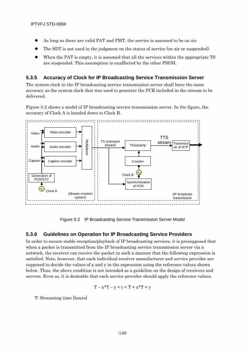
IPTVFJ STD-0004
-140-
As long as there are valid PAT and PMT, the service is assumed to be on air.
The SDT is not used in the judgment on the status of service (on air or suspended).
When the PAT is empty, it is assumed that all the services within the appropriate TS are suspended. This assumption is unaffected by the other PSI/SI.
5.3.5 Accuracy of Clock for IP Broadcasting Service Transmission Server The system clock in the IP broadcasting service transmission server shall have the same accuracy as the system clock that was used to generate the PCR included in the stream to be delivered.
Figure 5-2 shows a model of IP broadcasting service transmission server. In the figure, the accuracy of Clock A is handed down to Clock B.
Figure 5-2 IP Broadcasting Service Transmission Server Model
5.3.6 Guidelines on Operation for IP Broadcasting Service Providers In order to ensure stable reception/playback of IP broadcasting services, it is presupposed that when a packet is transmitted from the IP broadcasting service transmission server via a network, the receiver can receive the packet in such a manner that the following expression is satisfied. Note, however, that each individual receiver manufacturer and service provider are supposed to decide the values of x and y in the expression using the reference values shown below. Thus, the above condition is not intended as a guideline on the design of receivers and servers. Even so, it is desirable that each service provider should apply the reference values.
T – x*T – y < t < T + x*T + y
T: Streaming time [hours]
Timestamp
Video Video encoder
Audio encoder
Generation of PCR/STC
Caption encoder
Audio
Caption M
ultiplexer
Synchronization of PCR
Counter
Clock A
Clock B
Transmission of RTP
(Stream creation system)
TS (transport stream)
TTS stream
(IP broadcast transmission
IPTVFJ STD-0004
—141—
This indicates the time difference between TTS timestamp values at any two points in the stream received.
t: Time in which the receiver actually receives the packets that are transmitted within T
This indicates the time in which the packets within T are actually transmitted.
x: Coefficient indicating the accuracy of the IP broadcasting service transmission server clock [ms/hour] (Note 1).
This coefficient is 108 when the accuracy of the system clock used in the generation of PCR is handed down.
y: Jitter during reception of packet [ms].
The value of y represents the total of jitters in the IP broadcasting service transmission server and the network. In order to enable the receiver to perform the stream reception/playback operation stably and speedily, it is desirable that the value of y should be 100 or less. However, for the time being, the value of y may be up to approximately 300 if it is unavoidable due to difficulties involved in the operation of the transmission server.
Note 1: This coefficient does not include the clock error components, such as the PCR accuracy, inherent in the IP broadcasting service.
Packet bursts received by the receiver shall be a maximum of 3,125 KB (25 Mbps*) per second (157 KB ±100% per 50 ms). As a rule, the burst per 50 ms shall be operated in such a manner that it does not occur with consecutive packets.
* The value for the volume of data in an Ethernet packet at a TS rate of 18 Mbps when the Pro-MPEG 2D FEC is implemented.
Next, the method of confirming that the above guidelines are met is explained with an example. Figure 5-3 shows a method of measuring the quality of transmission. The IP broadcasting service transmission server is connected directly to a network analyzer, etc. The network analyzer directly receives the stream from the server. From the TTS timestamp information that is contained in the packets received and the timing information that indicates the actual reception time of the packets, it is possible to confirm its conformity to the guidelines.
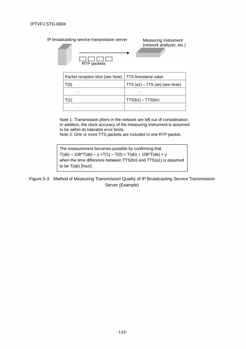
IPTVFJ STD-0004
-142-
Figure 5-3 Method of Measuring Transmission Quality of IP Broadcasting Service Transmission Server (Example)
Measuring instrument (network analyzer, etc.)
IP broadcasting service transmission server
RTP packets
The measurement becomes possible by confirming that T(ab) – 108*T(ab) – y <T(1) – T(0) < T(ab) + 108*T(ab) + y when the time difference between TTS(bn) and TTS(a1) is assumed to be T(ab) [hour].
Note 1: Transmission jitters in the network are left out of consideration. In addition, the clock accuracy of the measuring instrument is assumed to be within its tolerable error limits. Note 2: One or more TTS packets are included in one RTP packet.
Packet reception time (see Note) TTS timestamp value
T(0) TTS (a1) – TTS (an) (see Note)
: :
T(1) TTS(b1) – TTS(bn)
: :

IPTVFJ STD-0004
—143—
5.4 Assignment of Various Types of Values
5.4.1 Guidelines on Methods of Assigning Various Types of Values
5.4.1.1 Assignment of Value to Transport Stream Identifier (transport_stream_id) Assign a value to the 16-bit transport_stream_id in accordance with the following specifications.
The same value shall be assigned to transport_stream_id and service_id.
Neither the value 0x0000 nor the value 0xFFFF shall be assigned to transport_stream_id.
5.4.1.2 Service Identifier Assign to service_id a 3-digit decimal number converted to a 16-bit binary number.
5.4.1.3 IP Broadcaster ID (ip_broadcaster_id) On the assumption that a value is to be assigned to each of the IP broadcasting service providers within the network, ip_broadcaster_id shall be provided.
The guidelines on the assignment of a value to ip_broadcaster_id are as follows.
(1) The value 0x00 shall not be assigned.
(2) The values assigned shall be continuous starting from 0x01.
(3) The values assigned shall be binary.
5.4.2 Identifiers
5.4.2.1 Value of Network Identifier Each IP broadcasting service provider shall apply for a network identifier, to which a unique value is assigned by ARIB.
5.4.2.2 Values of Other Identifiers Of the following identifiers, the conditional access system identifier is provided by ARIB. Note, however, that the value assigned to this identifier is not unique to each IP broadcasting service provider: it is a value defined by the IPTV Standard.
Table 5-7 Values Assigned to Other Identifiers
Identifier Value Remarks Conditional access system identifier (CA_system_id)
0x00D

IPTVFJ STD-0004
-144-
Data component identifier (data_component_id)
Caption encoding system 0x0008 System management identifier (system_management_id)
broadcasting_flag: “01”
(non-broadcasting) broadcasting_identifi
er: “000001” (IP broadcasting)
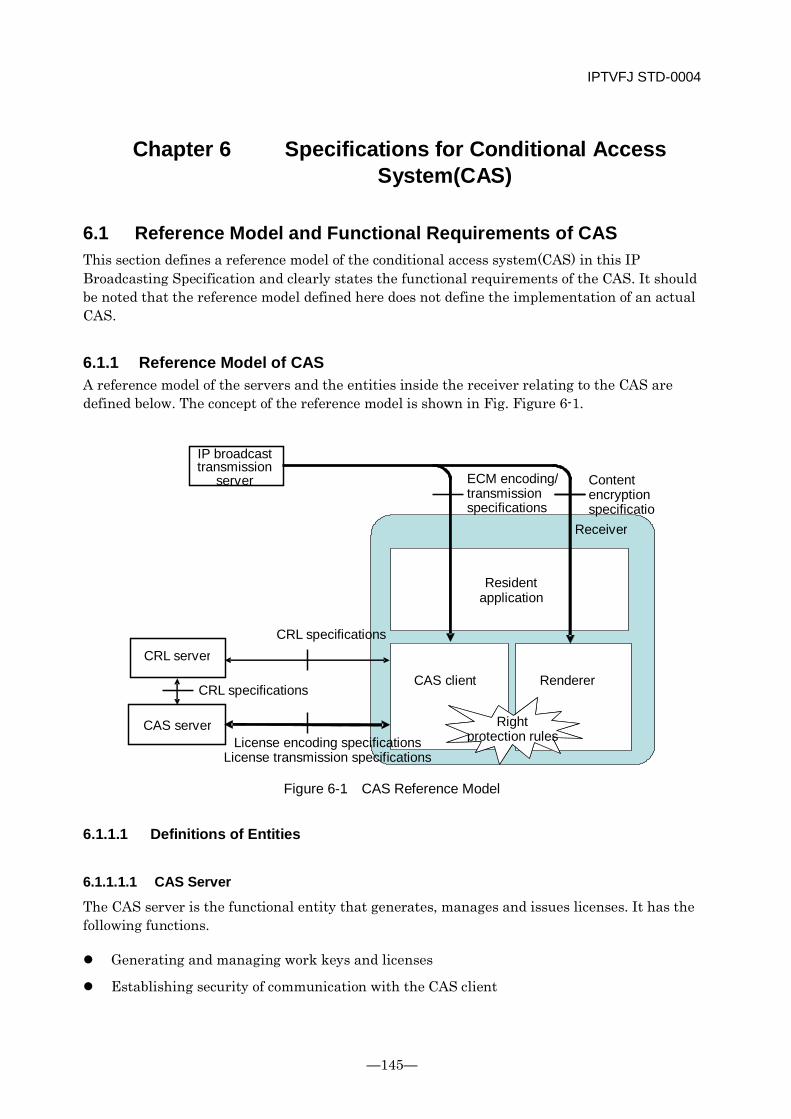
IPTVFJ STD-0004
—145—
Chapter 6 Specifications for Conditional Access System(CAS)
6.1 Reference Model and Functional Requirements of CAS This section defines a reference model of the conditional access system(CAS) in this IP Broadcasting Specification and clearly states the functional requirements of the CAS. It should be noted that the reference model defined here does not define the implementation of an actual CAS.
6.1.1 Reference Model of CAS A reference model of the servers and the entities inside the receiver relating to the CAS are defined below. The concept of the reference model is shown in Fig. Figure 6-1.
Figure 6-1 CAS Reference Model
6.1.1.1 Definitions of Entities
6.1.1.1.1 CAS Server
The CAS server is the functional entity that generates, manages and issues licenses. It has the following functions.
Generating and managing work keys and licenses
Establishing security of communication with the CAS client
IP broadcast transmission
server
CRL server
CAS server
Resident application
CAS client Renderer
Right protection rules
CRL specifications
License encoding specifications License transmission specifications
Content encryption specificatio
Receiver
ECM encoding/ transmission specifications
CRL specifications
IPTVFJ STD-0004
-146-
Judging whether or not to issue a license requested from the CAS client and transferring it to the CAS client where appropriate
Transferring trusted time information to the CAS client when requested
Generating scramble keys and sublicenses (ECM)
Updating and managing CRLs
6.1.1.1.2 CRL Server
The CRL server is the functional entity that generates, manages and issues CRLs relating to the CAS server and the CAS client. It has the following functions.
Generating, updating and managing CRLs of the CAS server and the CAS client
Transferring CRLs to the CAS server/CAS client when requested
6.1.1.1.3 IP Broadcast Transmission Server
The IP broadcast transmission server is the functional entity that transmits encrypted IP broadcasting service streams. It has the following function.
Multiplexing ECM and transmitting service streams encrypted by a scramble key
6.1.1.1.4 CAS Client
The CAS client is the functional entity within the receiver that acquires and manages licenses and supplies a scramble key to the renderer when content is used. It has the following functions.
Establishing a secure communication link through mutual authentication with the CAS server
Acquiring licenses from the CAS server and managing them
Extracting a scramble key from the ECM and supplying it to the renderer in IP broadcasting services
Updating and managing the CRLs through communication with the CRL server
6.1.1.1.5 Renderer
The renderer is the functional entity within the receiver that receives and decodes encrypted IP broadcasting service streams and reproduces contents. It has the following functions (It includes descrambler, demultiplexer, video decoder, audio decoder, caption decoder and presentation processing in the receiver model shown in 3.1).
Descrambling encrypted streams by using a scramble key obtained from the CAS client
Decoding descrambled streams
Implementing playback output control based on the information about conditions for the use of license obtained from the CAS client

IPTVFJ STD-0004
—147—
6.1.1.1.6 Resident Application
This is the software installed in the receiver to control the sequence of the entire process for implementing an IP broadcasting service.
6.1.1.2 CAS Specifications
6.1.1.2.1 License Encoding Specifications
These are the specifications on encoding licenses as a substance. They consist of work keys and information about conditions for the use of licenses.
6.1.1.2.2 License Transmission Specifications
These specifications define the communication protocols for establishing a secure communication link between the CAS client and the CAS server and for enabling the CAS server to deliver licenses safely. They represent important technical specifications that underlie the CAS, calling for a high degree of communication security through mutual authentication.
6.1.1.2.3 ECM Encoding/Transmission Specifications
These specifications define the encoding and transmission of the ECM packet that functions as the sublicense of the two-layer license model described later and that is multiplexed in a content stream in the IP broadcasting service.
6.1.1.2.4 Content Encryption Specifications
These specifications define the encryption of content streams in the IP broadcasting service.
6.1.1.2.5 CRL Specifications
These specifications define the encoding, transmission, updating and operation of the CRL that describes invalidated servers and the encoding, transmission, updating and operation of the CRL that describes unauthorized receivers (CAS clients).
6.1.1.2.6 Specifications on Rights Protection in Receivers
These specifications provide standards for the implementation of the CAS client and renderer and define the playback output control and copy control based on the information about conditions for use of licenses.
6.1.2 License Model
6.1.2.1 Definition of License The term “license” refers to the right to play or otherwise use specific content. Sometimes, it refers to data that shows the right to use specific content and that permits using the content
IPTVFJ STD-0004
-148-
only when the specified conditions for use are met. A license includes work keys, scramble key and information about the conditions for use of content.
6.1.2.2 License Delivery System In the IP broadcasting service, the license delivery system handles two layers of license — ECM and MC license. The ECM is the sublicense that is issued for each of contents and delivered together with the content, and the MC license is the main license that is delivered separately from the content according to the contract for use of content. The concept of license delivery in the IP broadcasting service is shown in the scheme of the license delivery system in Fig. 6-2.
The ECM (sublicense) that contains the key (scramble key: Ks) for encrypting an IP broadcast stream (content) and the information about the conditions for use of content (RMPIs) is encrypted using the work key Kw, and delivered together with the content (or as part of the content). On the other hand, the MC license (main license) that contains the work key Kw, and the general information about the conditions for use of content (RMPIm) is delivered separately from the content.
This delivery system is similar to the conditional access system in digital broadcasting. Namely, the ECM is, as a TS packet, multiplexed in the content stream before it is delivered. The scramble key Ks, contained in the ECM is renewed at certain intervals, and the decrypting part functions in receiver as a descrambler descrambles (decrypts) the stream. The flow of license delivery and use in the IP broadcasting service is explained below.
(1) The CAS server generates a work key (Kw) and an MC license (main license) containing the work key (Kw) and the information about the conditions for use of content (RMPIm).
(2) When requested from the CAS client, the CAS server delivers the MC license to the CAS client, which holds the MC license.
(3) The CAS server generates a scramble key (Ks) and an ECM packet as a sublicense containing the scramble key and the information about the conditions for use of content (RMPIs). Then, the contents server scrambles the content stream by using the scramble key (Ks), multiplexes the ECM packet in the stream, and transmits the stream.
(4) The receiver receives the content stream, extracts the ECM packet from the stream, and sends it to the CAS client. The CAS client decrypts the ECM by using the Kw contained in the MC license and checks the integrated condition from the two pieces of information regarding the conditions for use of content (RMPIm and RMPIs). When the CAS client confirms that the specified conditions for use of content are met, it takes out the scramble key (Ks) and sets it in the descrambler of the renderer.
(5) The renderer inside the receiver descrambles the content stream and subjects it to AV decoding. Concerning the playback output, the restrictions defined in the information about the conditions for use of content are applied.
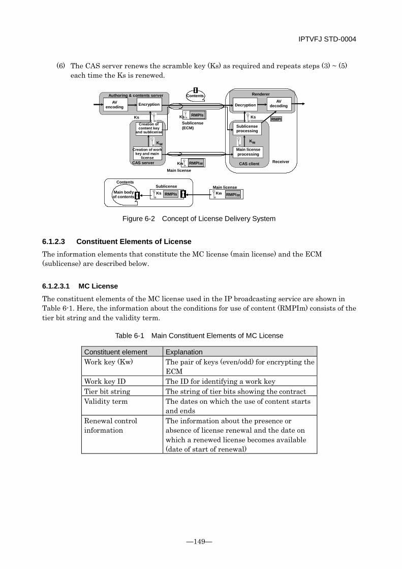
IPTVFJ STD-0004
—149—
(6) The CAS server renews the scramble key (Ks) as required and repeats steps (3) ~ (5) each time the Ks is renewed.
Figure 6-2 Concept of License Delivery System
6.1.2.3 Constituent Elements of License The information elements that constitute the MC license (main license) and the ECM (sublicense) are described below.
6.1.2.3.1 MC License
The constituent elements of the MC license used in the IP broadcasting service are shown in Table 6-1. Here, the information about the conditions for use of content (RMPIm) consists of the tier bit string and the validity term.
Table 6-1 Main Constituent Elements of MC License
Constituent element Explanation Work key (Kw) The pair of keys (even/odd) for encrypting the
ECM Work key ID The ID for identifying a work key Tier bit string The string of tier bits showing the contract Validity term The dates on which the use of content starts
and ends Renewal control information
The information about the presence or absence of license renewal and the date on which a renewed license becomes available (date of start of renewal)
K
Decryption
Main license processing
AV decoding
Ks
Kw RMPI m
Ks RMPI
Contents
Main license
Receiver CAS client
Renderer Authoring & contents server
Sublicense processing
K w K w
Ks RMPIs
Ks RMPIs Main body of contents
Sublicense Kw RMPI m
Main license Contents
AV encoding Encryption
Sublicense (ECM)
Creation of content key
and sublicense
Creation of work key and main
license CAS server
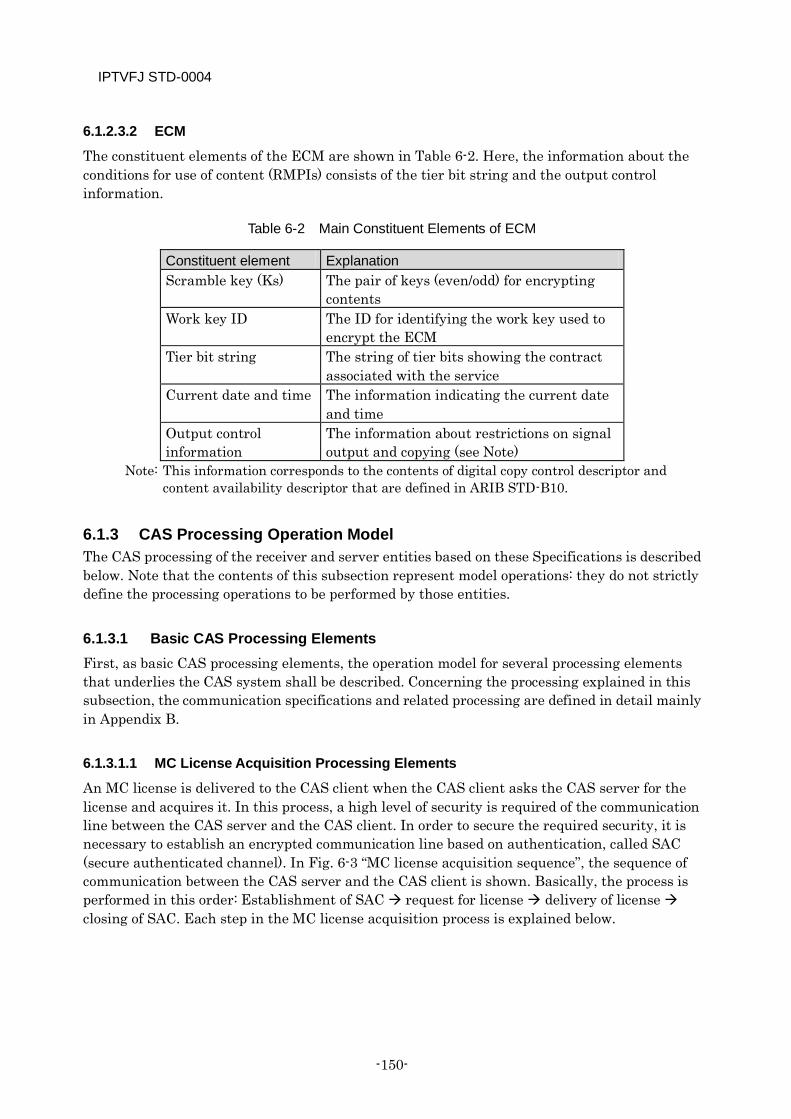
IPTVFJ STD-0004
-150-
6.1.2.3.2 ECM
The constituent elements of the ECM are shown in Table 6-2. Here, the information about the conditions for use of content (RMPIs) consists of the tier bit string and the output control information.
Table 6-2 Main Constituent Elements of ECM
Constituent element Explanation Scramble key (Ks) The pair of keys (even/odd) for encrypting
contents Work key ID The ID for identifying the work key used to
encrypt the ECM Tier bit string The string of tier bits showing the contract
associated with the service Current date and time The information indicating the current date
and time Output control information
The information about restrictions on signal output and copying (see Note)
Note: This information corresponds to the contents of digital copy control descriptor and content availability descriptor that are defined in ARIB STD-B10.
6.1.3 CAS Processing Operation Model The CAS processing of the receiver and server entities based on these Specifications is described below. Note that the contents of this subsection represent model operations: they do not strictly define the processing operations to be performed by those entities.
6.1.3.1 Basic CAS Processing Elements First, as basic CAS processing elements, the operation model for several processing elements that underlies the CAS system shall be described. Concerning the processing explained in this subsection, the communication specifications and related processing are defined in detail mainly in Appendix B.
6.1.3.1.1 MC License Acquisition Processing Elements
An MC license is delivered to the CAS client when the CAS client asks the CAS server for the license and acquires it. In this process, a high level of security is required of the communication line between the CAS server and the CAS client. In order to secure the required security, it is necessary to establish an encrypted communication line based on authentication, called SAC (secure authenticated channel). In Fig. 6-3 “MC license acquisition sequence”, the sequence of communication between the CAS server and the CAS client is shown. Basically, the process is performed in this order: Establishment of SAC request for license delivery of license closing of SAC. Each step in the MC license acquisition process is explained below.
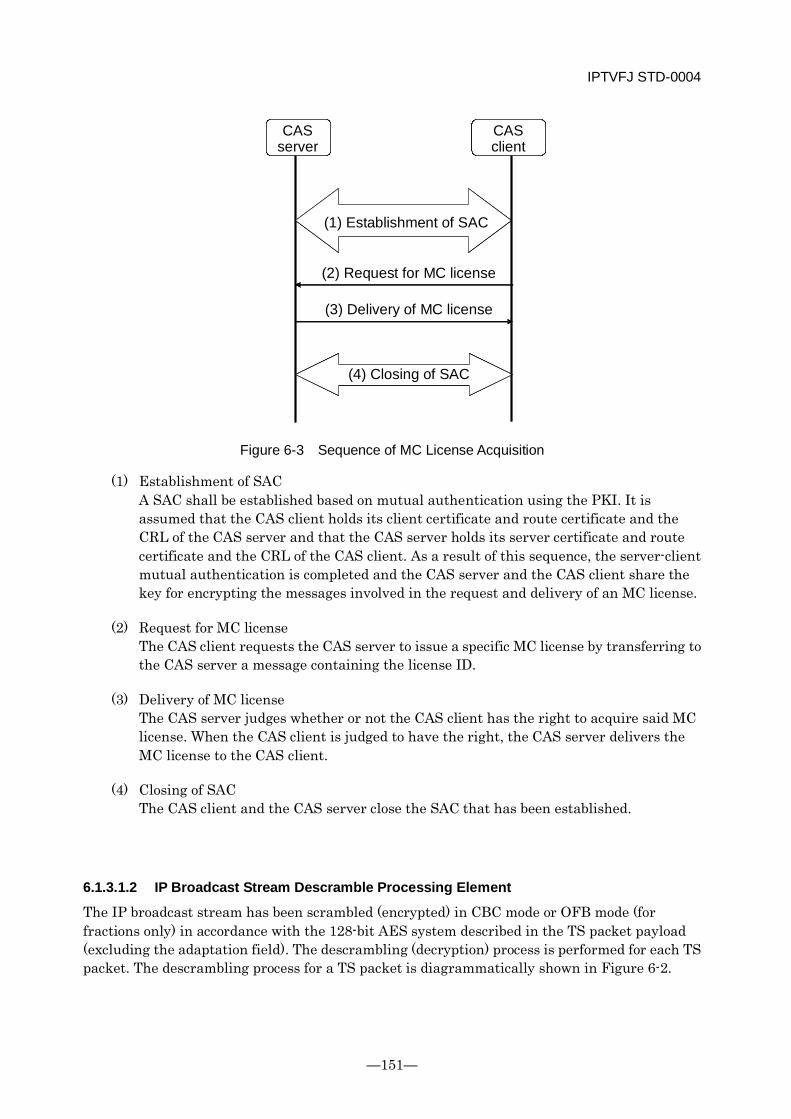
IPTVFJ STD-0004
—151—
Figure 6-3 Sequence of MC License Acquisition
(1) Establishment of SAC A SAC shall be established based on mutual authentication using the PKI. It is assumed that the CAS client holds its client certificate and route certificate and the CRL of the CAS server and that the CAS server holds its server certificate and route certificate and the CRL of the CAS client. As a result of this sequence, the server-client mutual authentication is completed and the CAS server and the CAS client share the key for encrypting the messages involved in the request and delivery of an MC license.
(2) Request for MC license The CAS client requests the CAS server to issue a specific MC license by transferring to the CAS server a message containing the license ID.
(3) Delivery of MC license The CAS server judges whether or not the CAS client has the right to acquire said MC license. When the CAS client is judged to have the right, the CAS server delivers the MC license to the CAS client.
(4) Closing of SAC The CAS client and the CAS server close the SAC that has been established.
6.1.3.1.2 IP Broadcast Stream Descramble Processing Element
The IP broadcast stream has been scrambled (encrypted) in CBC mode or OFB mode (for fractions only) in accordance with the 128-bit AES system described in the TS packet payload (excluding the adaptation field). The descrambling (decryption) process is performed for each TS packet. The descrambling process for a TS packet is diagrammatically shown in Figure 6-2.
CAS server
CAS client
(1) Establishment of SAC
(2) Request for MC license
(3) Delivery of MC license
(4) Closing of SAC
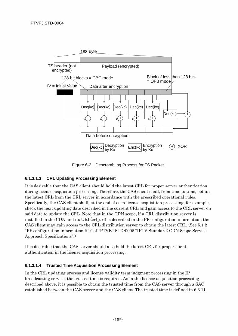
IPTVFJ STD-0004
-152-
Figure 6-2 Descrambling Process for TS Packet
6.1.3.1.3 CRL Updating Processing Element
It is desirable that the CAS client should hold the latest CRL for proper server authentication during license acquisition processing. Therefore, the CAS client shall, from time to time, obtain the latest CRL from the CRL server in accordance with the prescribed operational rules. Specifically, the CAS client shall, at the end of each license acquisition processing, for example, check the next updating date described in the current CRL and gain access to the CRL server on said date to update the CRL. Note that in the CDN scope, if a CRL distribution server is installed in the CDN and its URI (crl_url) is described in the PF configuration information, the CAS client may gain access to the CRL distribution server to obtain the latest CRL. (See 5.1.2 “PF configuration information file” of IPTVFJ STD-0006 “IPTV Standard: CDN Scope Service Approach Specifications”.)
It is desirable that the CAS server should also hold the latest CRL for proper client authentication in the license acquisition processing.
6.1.3.1.4 Trusted Time Acquisition Processing Element
In the CRL updating process and license validity term judgment processing in the IP broadcasting service, the trusted time is required. As in the license acquisition processing described above, it is possible to obtain the trusted time from the CAS server through a SAC established between the CAS server and the CAS client. The trusted time is defined in 6.3.11.
+
128-bit blocks = CBC mode
Dec(kc)
Dec(kc) +
Data before encryption
Dec(kc)
+
Dec(kc)
+
Dec(kc)
+
Dec(kc)
+
188 byte
Payload (encrypted)
+ XOR Dec(kc) Enc(kc)
IV = Initial Value Data after encryption
Block of less than 128 bits = OFB mode
Decryption by Kc
Encryption by Kc
TS header (not encrypted)
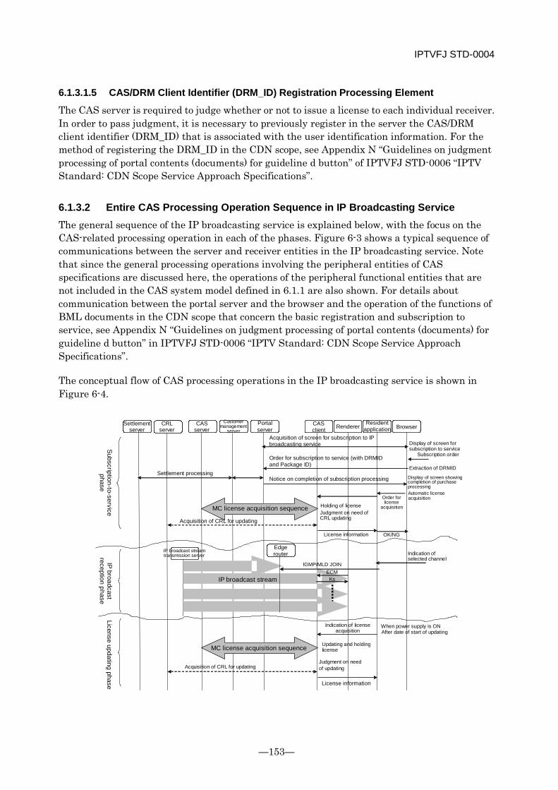
IPTVFJ STD-0004
—153—
6.1.3.1.5 CAS/DRM Client Identifier (DRM_ID) Registration Processing Element
The CAS server is required to judge whether or not to issue a license to each individual receiver. In order to pass judgment, it is necessary to previously register in the server the CAS/DRM client identifier (DRM_ID) that is associated with the user identification information. For the method of registering the DRM_ID in the CDN scope, see Appendix N “Guidelines on judgment processing of portal contents (documents) for guideline d button” of IPTVFJ STD-0006 “IPTV Standard: CDN Scope Service Approach Specifications”.
6.1.3.2 Entire CAS Processing Operation Sequence in IP Broadcasting Service The general sequence of the IP broadcasting service is explained below, with the focus on the CAS-related processing operation in each of the phases. Figure 6-3 shows a typical sequence of communications between the server and receiver entities in the IP broadcasting service. Note that since the general processing operations involving the peripheral entities of CAS specifications are discussed here, the operations of the peripheral functional entities that are not included in the CAS system model defined in 6.1.1 are also shown. For details about communication between the portal server and the browser and the operation of the functions of BML documents in the CDN scope that concern the basic registration and subscription to service, see Appendix N “Guidelines on judgment processing of portal contents (documents) for guideline d button” in IPTVFJ STD-0006 “IPTV Standard: CDN Scope Service Approach Specifications”.
The conceptual flow of CAS processing operations in the IP broadcasting service is shown in Figure 6-4.
ECM
OK/NG
IGMP/MLD JOIN ECM
Ks
Settlement server
CRL server
CAS server
Customer management
server Portal server
CAS client Renderer
Resident application Browser
Subscription-to-service phase
Settlement processing
Acquisition of screen for subscription to IP broadcasting service Display of screen for
subscription to service
Order for subscription to service (with DRMID and Package ID)
Subscription order
Extraction of DRMID
Notice on completion of subscription processing Display of screen showing completion of purchase processing Automatic license acquisition
MC license acquisition sequence Holding of license Judgment on need of CRL updating
Order for license
acquisition
Acquisition of CRL for updating
License information
IP broadcast reception phase
IP broadcast stream transmission server
Edge router Indication of
selected channel
IP broadcast stream
License updating phase
MC license acquisition sequence
Indication of license acquisition
When power supply is ON After date of start of updating
Updating and holding license
Acquisition of CRL for updating Judgment on need of updating
License information
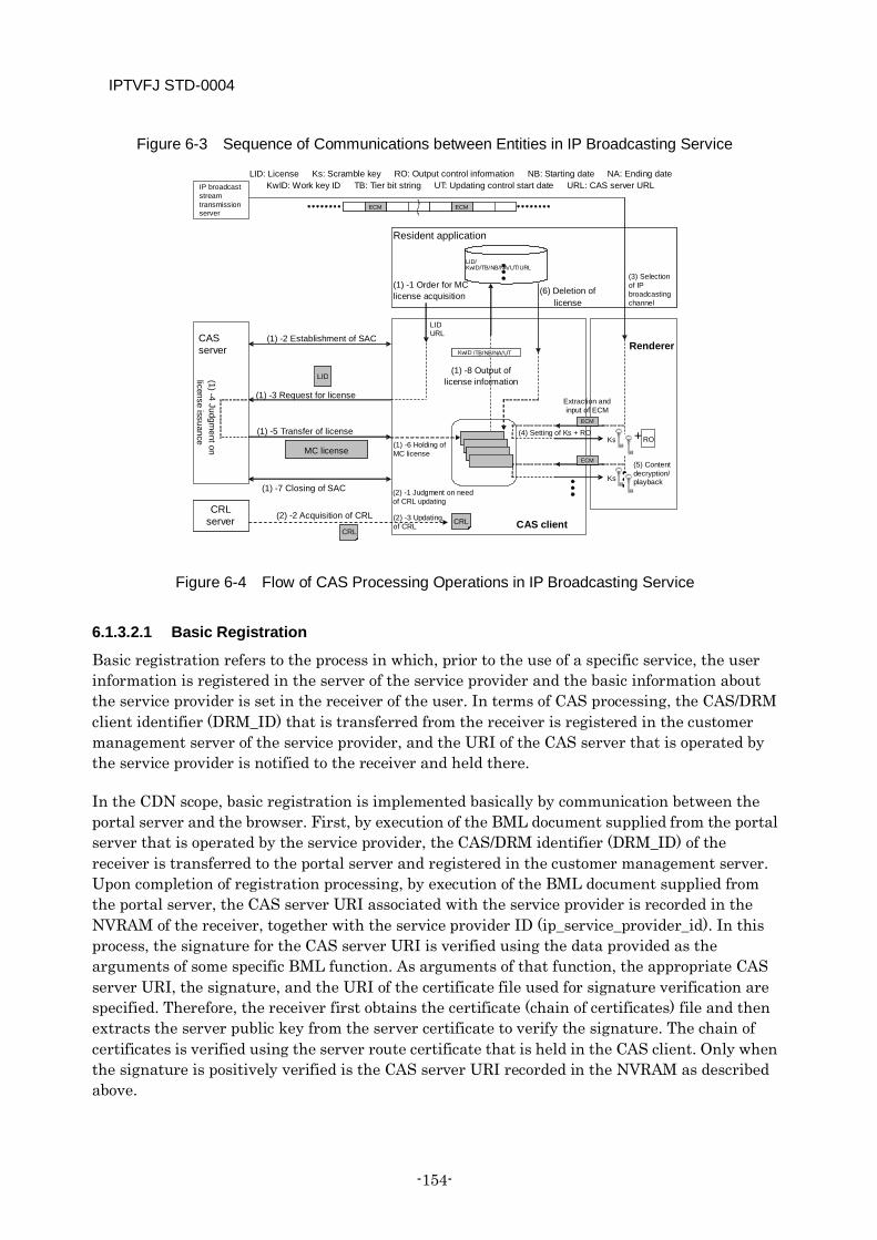
IPTVFJ STD-0004
-154-
Figure 6-3 Sequence of Communications between Entities in IP Broadcasting Service
Figure 6-4 Flow of CAS Processing Operations in IP Broadcasting Service
6.1.3.2.1 Basic Registration
Basic registration refers to the process in which, prior to the use of a specific service, the user information is registered in the server of the service provider and the basic information about the service provider is set in the receiver of the user. In terms of CAS processing, the CAS/DRM client identifier (DRM_ID) that is transferred from the receiver is registered in the customer management server of the service provider, and the URI of the CAS server that is operated by the service provider is notified to the receiver and held there.
In the CDN scope, basic registration is implemented basically by communication between the portal server and the browser. First, by execution of the BML document supplied from the portal server that is operated by the service provider, the CAS/DRM identifier (DRM_ID) of the receiver is transferred to the portal server and registered in the customer management server. Upon completion of registration processing, by execution of the BML document supplied from the portal server, the CAS server URI associated with the service provider is recorded in the NVRAM of the receiver, together with the service provider ID (ip_service_provider_id). In this process, the signature for the CAS server URI is verified using the data provided as the arguments of some specific BML function. As arguments of that function, the appropriate CAS server URI, the signature, and the URI of the certificate file used for signature verification are specified. Therefore, the receiver first obtains the certificate (chain of certificates) file and then extracts the server public key from the server certificate to verify the signature. The chain of certificates is verified using the server route certificate that is held in the CAS client. Only when the signature is positively verified is the CAS server URI recorded in the NVRAM as described above.
ECM RO + Ks
ECM Ks
LID
LID URL
KwID /TB/NB/NA/UT
LID/ KwID /TB/NB/NA/UT/URL
ECM ECM
ECM RO + Ks
ECM Ks
LID
CRL CRL
IP broadcast stream transmission server
Resident application
(1) -1 Order for MC license acquisition
(6) Deletion of license
(3) Selection of IP broadcasting channel
CAS server
(1) -2 Establishment of SAC
(1) -3 Request for license
(1) -4 Judgment on
license issuance
(1) -5 Transfer of license
MC license
(1) -7 Closing of SAC
CAS client
(1) -6 Holding of MC license
(1) -8 Output of license information
Extraction and input of ECM
(4) Setting of Ks + RO
(2) -1 Judgment on need of CRL updating
(2) -3 Updating of CRL
CRL server (2) -2 Acquisition of CRL
Renderer
(5) Content decryption/ playback
LID: License Ks: Scramble key RO: Output control information NB: Starting date NA: Ending date KwID: Work key ID TB: Tier bit string UT: Updating control start date URL: CAS server URL
IPTVFJ STD-0004
—155—
6.1.3.2.2 Subscription to Service
In the IP broadcasting service, subscription to service refers to the process in which a contract for the use of a specific IP broadcasting service is signed to enable the user to enjoy the service. In terms of CAS processing, the CAS server of the service provider makes it possible for the receiver of the subscriber to acquire a license for the service subscribed to and then, the receiver acquires an MC license for said service.
In the CDN scope, subscription to service is implemented basically by communication between the portal server and the browser. First, on the subscription-to-service page of the BML document supplied by the portal server, user authentication is implemented using the DRM_ID shown in Appendix V “Annotation: User Authentication in Portal Service” in IPTVFJ STD-0006 “IPTV Standard: CDN-scope Service Approach Specifications”. Then, the user performs the operation to sign a monthly contract for a specific IP broadcasting service package. At this time, the script on the BML document is executed and the appropriate package identification information is registered in the customer management server via the portal server. As long as the user’s personal information has been associated with the DRM_ID by basic registration, the customer management server can communicate with the settlement server to collect the charge involved in the subscription to service. In addition, since the above DRM_ID is associated with the license ID from the package identification information, the DRM_ID and the license ID are associated with each other and registered in the customer management server.
On the other hand, the license acquisition function that is described in the BML document for notification of the completion of subscription to service is executed to start the following license acquisition processing.
(1) License acquisition/holding process By executing the license acquisition function, the CAS client first reads out, the CAS server URI that has been recorded in its NVRAM during basic registration, refering the service provider ID (ip_service_provider_id) given as one of the arguments of the above function, and then performs the license acquisition processing described in 6.1.3.1.1 to obtain the MC license containing a pair of work keys (even key and odd key) from the CAS server. The MC license obtained is associated with the license ID and held in the NVRAM of the CAS client for management. It should be noted that when the contracted IP broadcasting service package requires more than one MC license, it is necessary to obtain all the required MC licenses. By using the above license acquisition function, however, it is possible to obtain them at the same time. The work key ID, tier bit string, validity term and time to start renewal that are contained in the MC license are so managed that they can be used by the resident application. In addition, ip_service_provider_id that is set as an argument of the above license acquisition function is associated with the acquired license for management (in order to obtain the CAS server URI of each individual service provider when renewing the license).
(2) CRL updating process Judgment is passed as to whether or not to update the CRL. Where necessary, the CRL updating process described in 6.1.3.1.3 is performed.
IPTVFJ STD-0004
-156-
In the CDN scope, it is conceivable that the subscription to service will be implemented off-line by telephone, mail, etc., rather than on-line by the BML document of the portal service. In this particular case, although the subscription to service is registered in the customer management server, the necessary license is not obtained by the receiver. Therefore, even after a service is subscribed to, the user cannot enjoy the service. It should be noted, however, that as shown in Appendix N “Guidelines on Decision Process in Portal Documents for d button” in IPTVFJ STD-0006 “IPTV Standard: CDN-scope Service Approach Specifications”, even in the above case, it is possible to enable the user to enjoy the service by following this procedure. First, while the appropriate service channel is selected, operate the d button to execute the BML document supplied by the service provider. In this BML document, it is possible to recognize the fact that the contract has been concluded through communication with the portal server but that the necessary license has not been obtained. Then, execute the license acquisition function.
6.1.3.2.3 Reception and Playback of IP Broadcasting Service
Once the MC license is obtained, the resident application of the receiver matches the work key ID and tier bit string contained in the license with the CA contract information descriptor in the SDT to permit the EPG to display the contracted service. When the user selects the contracted IP broadcasting service channel from the EPG or by means of direct channel selection, etc., the following process is performed.
(3) Selection of IP broadcasting service channel A JOIN message of the IGMP or MLD is sent to the edge router to select the specified service channel and receive the service stream.
(4) ECM processing The DEMUX extracts the ECM using the conditional access system descriptor inserted in the service stream PMT. The ECM is then transferred to the CAS client. As long as the MC license associated with the ECM is within the term of validity and both the ECM and MC license have at least one tier bit which is “1” in the same bit position, the ECM is decrypted by the work key (Kw) and the scramble key pair (Ks odd/even) is extracted from the ECM and set in the descrambler of the renderer. The scramble key pair is not output if the MC license specified by the ECM does not exist in the CAS client or if none of the tier bits of the MC license and ECM in the same bit position are “1” or if the term of validity of the MC license has expired. Judging whether or not the MC license is within the term of validity requires using the trusted time, which is described in 6.1.3.1.4. When the scramble key pair is output to enable playback of the service stream, the output control information contained in the ECM is also output to the renderer.
(5) Content decoding and playback The service stream is first descrambled by the descrambler and then subjected to AV decoding before it is reproduced and output. In this process, the output is controlled based on the output control information obtained from the ECM.
IPTVFJ STD-0004
—157—
6.1.3.2.4 Contract Renewal/Cancellation and License Renewal
In the IP broadcasting service, it is presupposed that flat service contracts (e.g., monthly contracts) are automatically renewed unless they are canceled. Therefore, it is presupposed that in the case of a monthly contract, the date of expiration of the contract is set to be, say, the end of each month throughout the period of automatic contract renewal and the license is renewed on or after the date of start of renewal set before the date of expiration of the contract. Specifically, based on the information about the date of start of renewal managed by the resident application, the receiver, during power input, etc. after the lapse of the date of start of renewal, re-acquires the MC license containing the work key pair (even and odd keys) as described in 6.1.3.2.2 and renews the old MC license by overwriting the new MC license of the same license ID on it. In the CDN scope, when re-acquiring the MC license, the receiver determines, from the ip_service_provider_id associated with the license that has been recorded in the receiver, the CAS server URI of the appropriate service provider that was recorded during the basic registration and uses the URI. It is also assumed that in consideration of security during license renewal, the work key will be renewed as required. Figure 6-5 shows two examples of license renewal. In one example, the work key is renewed during license renewal and in the other the work key is not renewed during license renewal.
In terms of CAS processing, canceling a service basically requires the receiver to cut off the chain of automatic renewal of the MC license. However, depending on the type of operation of the service provider and the terms of the contract, there can be a number of variations in the cancellation process. The presupposed operation for canceling a service in the CDN scope is explained below.
It is assumed that like the subscription to a service, the cancellation of a service is basically implemented on-line by communication between the portal server and the browser. On the service cancellation page of the BML document supplied by the portal server, the user performs the processing for canceling a specific IP broadcasting service package that has been under contract. Then, the script on the BML document is executed and the appropriate package identification information is transmitted to the customer management server via the portal server.
If, in addition to the canceled package, there is a package under contract within a specific work key (another tier bit that has been set exists), it is possible to enable the user to continue viewing even the canceled package until the end of the month by the following operation. In the document notifying completion of the cancellation, the date on which the viewing of the canceled package is disabled is set as the date of start of service renewal, and the user is made first to acquire a license of the same tier bit string as before and then to acquire another license with only the set tier bit of the canceled package reset next time the license is renewed.
If the canceled package is the only package within a specific work key (the only tier bit set), it is possible to disable further renewal of the license by making the user acquire a license with “No renewal” specified in the BML document notifying the cancellation. In this case, after the term of validity of the license expires, the resident application deletes said license when the power is switched on. Figure 6-6 shows an example of license renewal control implemented during service cancellation. What has been described above is just one example of a use case relating to a service contract. Various use cases for license acquisition (renewal) relating to the signing,
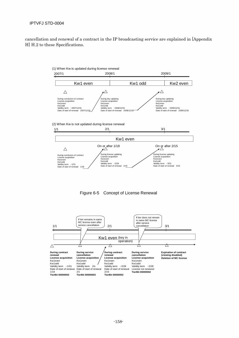
IPTVFJ STD-0004
-158-
cancellation and renewal of a contract in the IP broadcasting service are explained in [Appendix H] H.2 to these Specifications.
Figure 6-5 Concept of License Renewal
Kw1 even Kw1 odd Kw2 even
2007/1 2008/1 2009/1
(1) When Kw is updated during license renewal
Kw1 even
1/1 2/1 3/1
During conclusion of contract License acquisition Kw1even Kw1odd Validity term ~2007/12/31 Date of start of renewal 2007/12/18
During key updating License acquisition Kw1even Kw1odd Validity term ~2008/12/31 Date of start of renewal 2008/12/18
During key updating License acquisition Kw1even Kw1odd Validity term ~2009/12/31 Date of start of renewal 2009/12/18
(2) When Kw is not updated during license renewal
During conclusion of contract License acquisition Kw1even Kw1odd Validity term ~1/31 Date of start of renewal 1/18
On or after 1/18 On or after 2/15
During license updating License acquisition Kw1even Kw1odd Validity term ~2/28 Date of start of renewal 2/15
During license updating License acquisition Kw1even Kw1odd Validity term ~3/31 Date of start of renewal 3/15
Kw1 even (key in operation)
1/1
2/1 3/1
If tier remains in same MC license even after service cancellation
If tier does not remain in same MC license after service cancellation
During contract renewal License acquisition Kw1even Kw1odd Validity term ~1/31 Date of start of renewal 1/18 TierBit 00000003
During service cancellation License acquisition Kw1even Kw1odd Validity term 2/x Date of start of renewal 2/1 TierBit 00000003
During contract renewal License acquisition Kw1even Kw1odd Validity term ~2/28 Date of start of renewal 2/15 TierBit 00000002
During service cancellation License acquisition Kw1even Kw1odd Validity term ~2/28 License not renewed TierBit 00000002
Expiration of contract (viewing disabled) Deletion of MC license
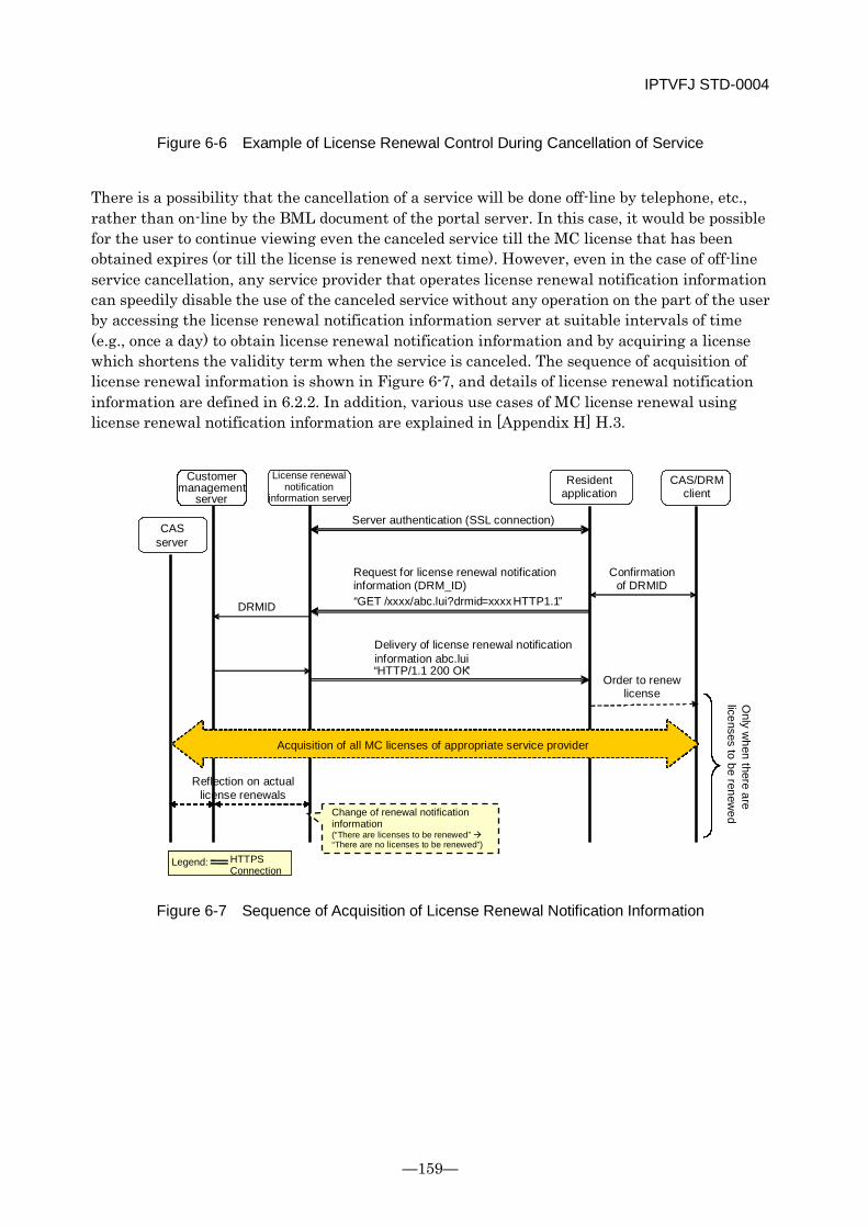
IPTVFJ STD-0004
—159—
Figure 6-6 Example of License Renewal Control During Cancellation of Service
There is a possibility that the cancellation of a service will be done off-line by telephone, etc., rather than on-line by the BML document of the portal server. In this case, it would be possible for the user to continue viewing even the canceled service till the MC license that has been obtained expires (or till the license is renewed next time). However, even in the case of off-line service cancellation, any service provider that operates license renewal notification information can speedily disable the use of the canceled service without any operation on the part of the user by accessing the license renewal notification information server at suitable intervals of time (e.g., once a day) to obtain license renewal notification information and by acquiring a license which shortens the validity term when the service is canceled. The sequence of acquisition of license renewal information is shown in Figure 6-7, and details of license renewal notification information are defined in 6.2.2. In addition, various use cases of MC license renewal using license renewal notification information are explained in [Appendix H] H.3.
Figure 6-7 Sequence of Acquisition of License Renewal Notification Information
DRMID
“ HTTP/1.1 200 OK ”
“ GET / xxxx/abc.lui ? drmid = xxxx HTTP1.1 ”
Customer management
server License renewal
notification information server
Resident application
CAS/DRM client
CAS server
Server authentication (SSL connection)
Request for license renewal notification information (DRM_ID)
Confirmation of DRMID
Delivery of license renewal notification information abc.lui
Order to renew license
Acquisition of all MC licenses of appropriate service provider
Only w
hen there are licenses to be renew
ed
Reflection on actual license renewals
Legend: HTTPS Connection
Change of renewal notification information (“There are licenses to be renewed” “There are no licenses to be renewed”)
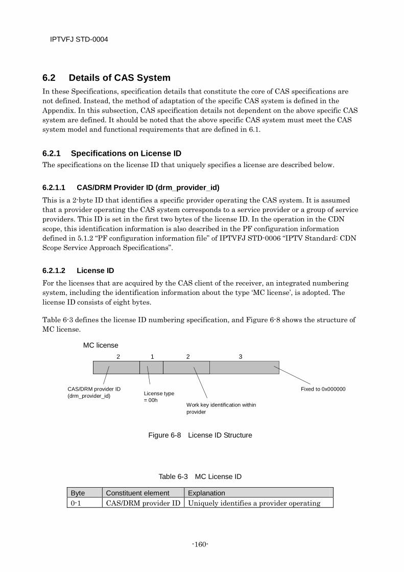
IPTVFJ STD-0004
-160-
6.2 Details of CAS System In these Specifications, specification details that constitute the core of CAS specifications are not defined. Instead, the method of adaptation of the specific CAS system is defined in the Appendix. In this subsection, CAS specification details not dependent on the above specific CAS system are defined. It should be noted that the above specific CAS system must meet the CAS system model and functional requirements that are defined in 6.1.
6.2.1 Specifications on License ID The specifications on the license ID that uniquely specifies a license are described below.
6.2.1.1 CAS/DRM Provider ID (drm_provider_id) This is a 2-byte ID that identifies a specific provider operating the CAS system. It is assumed that a provider operating the CAS system corresponds to a service provider or a group of service providers. This ID is set in the first two bytes of the license ID. In the operation in the CDN scope, this identification information is also described in the PF configuration information defined in 5.1.2 “PF configuration information file” of IPTVFJ STD-0006 “IPTV Standard: CDN Scope Service Approach Specifications”.
6.2.1.2 License ID For the licenses that are acquired by the CAS client of the receiver, an integrated numbering system, including the identification information about the type ‘MC license’, is adopted. The license ID consists of eight bytes.
Table 6-3 defines the license ID numbering specification, and Figure 6-8 shows the structure of MC license.
Figure 6-8 License ID Structure
Table 6-3 MC License ID
Byte Constituent element Explanation 0-1 CAS/DRM provider ID Uniquely identifies a provider operating
2 1 2 3 MC license
CAS/DRM provider ID (drm_provider_id) License type
= 00h Work key identification within provider
Fixed to 0x000000
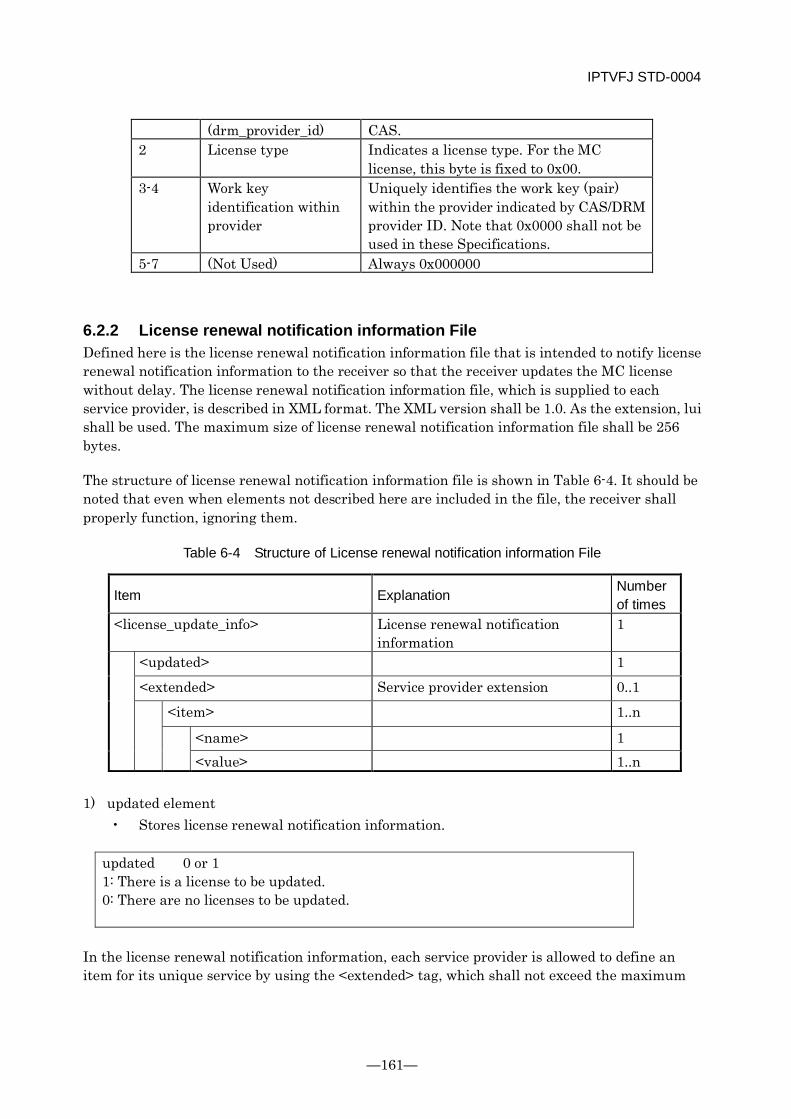
IPTVFJ STD-0004
—161—
(drm_provider_id) CAS. 2 License type Indicates a license type. For the MC
license, this byte is fixed to 0x00. 3-4 Work key
identification within provider
Uniquely identifies the work key (pair) within the provider indicated by CAS/DRM provider ID. Note that 0x0000 shall not be used in these Specifications.
5-7 (Not Used) Always 0x000000
6.2.2 License renewal notification information File Defined here is the license renewal notification information file that is intended to notify license renewal notification information to the receiver so that the receiver updates the MC license without delay. The license renewal notification information file, which is supplied to each service provider, is described in XML format. The XML version shall be 1.0. As the extension, lui shall be used. The maximum size of license renewal notification information file shall be 256 bytes.
The structure of license renewal notification information file is shown in Table 6-4. It should be noted that even when elements not described here are included in the file, the receiver shall properly function, ignoring them.
Table 6-4 Structure of License renewal notification information File
Item Explanation Number of times
<license_update_info> License renewal notification information
1
<updated> 1 <extended> Service provider extension 0..1 <item> 1..n
<name> 1 <value> 1..n
1) updated element
• Stores license renewal notification information.
updated 0 or 1 1: There is a license to be updated. 0: There are no licenses to be updated.
In the license renewal notification information, each service provider is allowed to define an item for its unique service by using the <extended> tag, which shall not exceed the maximum

IPTVFJ STD-0004
-162-
file size. In this case, in order to prevent the duplication of an item between service providers, the item name in the <name> tag shall be prefixed with “x-alphanumeric characters-” (these characters are unique to each service provider), like x-abc123-itemname. The operation of the receiver when the receiver receives an item unique to each service provider shall be left to how the receiver is implemented. If the receiver receives an item which cannot be interpreted, it shall ignore the item.
IPTVFJ STD-0004
—163—
6.3 CAS Related Functional Requirements for Receivers As a rule, the receiver is required to perform the processing that is performed by the operation model shown in 6.1.3 and the specific receiver processing that is defined in 6.2 and by the applicable CAS system.
The other types of CAS processing that are required to be performed by the receiver, related specifications and special remarks are described below. Note that the CAS functions shall be made available only in services of the service providers that have completed basic registration.
6.3.1 Dealing with Error in License Acquisition Processing It is conceivable that the receiver fails to obtain a license if any of the following events occurred during license acquisition processing.
(1) Connection with the CAS server failed. The timeout value for the receiver in its attempt to acquire a license depends on how the receiver has been implemented. In any case, however, it is not longer than 10 seconds.
(2) Establishment of an SAC failed due to server authentication error, client authentication error, etc.
(3) The CAS server rejected the receiver’s request for a license because the service had not been subscribed to, preventing the receiver from obtaining an effective license.
(4) The session for license acquisition could not be completed due to some trouble with the network or server.
If any of the above events has occurred, it is desirable to perform the following error processing according to the sequence of license acquisition.
In the operation in the CDN scope, if any of the above events has occurred during license acquisition using the license acquisition function that is defined in Chapter 6 “Specifications of BML for IPTV” of IPTVFJ STD-0006 “IPTV Standard: CDN Scope Service Approach Specifications”, terminate the operation of the function in accordance with the Specifications.
Concerning the receiver operation to be performed if any of the above events has occurred during license acquisition for renewal of the MC license, no special specifications are provided. However, it is necessary for the receiver to retry the acquisition of license taking into account the requirements described in 6.3.3. In the CDN scope, when the error has occurred, it is also desirable that the receiver should display the appropriate error code and error message that are defined in Chapter 3 “Receiver Specifications” of IPTVFJ STD-0006 “IPTV Standard: CDN-scope Service Approach Specifications”.
IPTVFJ STD-0004
-164-
6.3.2 Holding and Managing Licenses In order for the receiver to implement the CAS-related functions based on these Specifications, it is necessary that the receiver should hold and manage the acquired licenses as described below.
Concerning the MC license, it is assumed that the receiver acquires one each time it subscribes to a service. Since the receiver needs to hold and manage the MC license as long as the service contract continues in existence, an NVRAM that is capable of holding more than one MC license is required of the receiver. Although the capacity of the NVRAM used for that purpose is left to each individual receiver, it is necessary to determine the optimum capacity taking into consideration the number of service providers involved and the operation of the work keys of those service providers. In addition, the receiver shall manage the term of validity of each MC license and invalidate any MC license that has expired.
6.3.3 License Renewal Processing The operation for renewing an MC license is as defined in 6.1.3.2.4 of these Specifications. In order to implement this operation, it is desirable that the receiver should hold the information about when to start renewal of a specific license and should, without delay, perform the license re-acquisition processing when the renewal time has passed. It should be noted that when the time interval between the renewal time and the date of expiration of the license is short, the license re-acquisition processing should be speedily performed by the date of expiration. Otherwise, it becomes impossible for the receiver to receive the service despite the fact that the service contract is still valid.
6.3.4 Acquisition of License Renewal Information If the service provider operates license renewal information, the receiver may connect to the license renewal information server of the service provider and obtain license renewal information defined in 6.2.2.
To obtain the above information, the receiver uses GET of the HTTPS.
In the CDN scope, when the receiver connects to the license renewal information server, the HTTP authentication system defined in 5.5.8 “Authentication on Resident Applications” of IPTVFJ STD-0006 “IPTV Standard: CDN Scope Service Approach Specifications” shall be used to identify the user to whom the license renewal information is to be supplied.
Here, whether or not to renew the service provider’s MC license held by the receiver is checked. If the MC license is to be renewed, the CAS client shall acquire all the MC licenses of the service provider and rewrite them on the existing licenses even when the time to start renewal has not come yet.
Even when license renewal information is operated, the receiver shall hold the above information about the time to start license renewal and perform the license renewal processing when the time to start renewal has passed.
IPTVFJ STD-0004
—165—
It is desirable that the receiver should access the renewal inquiry server when the receiver is active and 24 hours or more have elapsed from the previous license acquisition.
In notifying the license renewal information, the time that is sufficient for the license renewal information server to perform the necessary processing shall be 15 seconds. Although the processing to be performed by the receiver when the server does not make any response within 15 seconds is left to how the receiver has been implemented, it is desirable that the receiver should retry several times at certain intervals.
6.3.5 Pay/Free Programs and Scrambling in IP Broadcasting Service In the IP broadcasting service, pay programs shall mean scrambled ones and free programs shall mean non-scrambled ones. (In actual operation, programs which are scrambled free of charge are conceivable. These programs are handled as pay programs for which ¥0 is charged.) Pay programs and free programs are distinguished from each other by free_CA_mode in the SDT and EIT. Pay programs constitute the pay service associated with the SDT whose free_CA_mode is “1”. The SDT of pay services always contains a CA contract information descriptor, and the pay services are subject to conditional access. On the other hand, ordinarily, free programs constitute the free service associated with the SDT whose free_CA_mode is “0”. The SDT of free services does not contain a CA contract information descriptor, and the free services are always non-scrambled. It should be noted, however, that there are cases in which a free program with free_CA_mode = 0 set in the EIT is included in a pay service with free_CA_mode =1 set in the SDT. (In such cases, the switching between scrambled program and non-scrambled program is done.) It should also be noted that there is no such thing as a free program requiring content protection.
The processing of a scrambled program shall be performed in the same way as the reception processing described in 6.1.3.2.3. While the ECM processing is performed based on ECM_PID shown in the conditional access system descriptor in the first loop of the PMT, the scrambled program is descrambled with reference to the scramble control flag of the TS scramble header. In no cases is a conditional access system descriptor inserted in the second loop of the PMT. Therefore, neither charging by component nor non-scrambling of only specific elementary streams (e.g., caption ES) is implemented. In the period of transition from scrambling to non-scrambling, etc., the ECM is not always sent out even when the conditional access system descriptor has been inserted in the first loop of the PMT. Even in this case, the descrambling process shall be continued with reference to the scramble control flag of the TS scramble header.
Non-scrambled programs do not require the above ECM processing since the conditional access system descriptor is absent. However, whether or not to refer to the scramble control flag of the TS packet header shall be optional. The processing to be performed when the receiver receives a stream whose scramble flag is ON shall be left to each individual receiver. If an error occurs during the reception, however, it is desirable that the receiver should display the appropriate error code and error message defined in Chapter 3 “Receiver Specifications” of IPTVFJ STD-0006 “IPTV Standard: CDN Scope Service Approach Specifications”.
IPTVFJ STD-0004
-166-
6.3.6 Program Reservation in IP Broadcasting Service When the receiver is going to reserve a pay program whose free_CA_mode in the EIT is 1, it uses the license ID and tier bit mask described in the CA contract information descriptor of the SDT to determine whether or not the program is viewable. Namely, when the upper five bytes of the license ID and the upper five bytes of the work key ID contained in the MC license that has already been acquired have the same value and when the AND between the tier bit string and the tier bit mask is not 0, the receiver judges the program viewable and performs reservation processing. (In order to perform reservation processing based on the above judgment, it is necessary for the receiver to hold the work key ID and tier bit string contained in the acquired MC license throughout the term of validity of the license.) When the receiver is going to record a pay program, it judges whether or not it is allowed to record the program from the digital copy control descriptor in the EIT.
After the term of validity of the license has expired, it is necessary to reflect it in the work key ID and tier bit string information without delay in order to disable the reservation of programs. On the other hand, when a program is reserved before expiration of the term of validity of the license, it is desirable that the receiver should perform the program reservation processing to permit viewing the program even if the program is scheduled to be broadcast some time after the date of expiration, on the assumption that the license will be renewed. It should be noted, however, that when the service contract is canceled after the reservation of a program, it might become impossible to view the program despite the fact that it has been reserved.
When a free program whose free_CA_mode in the EIT is 0, the receiver judges that the program can be reserved unconditionally.
6.3.7 Receiver Operation When Revoked If the receiver is revoked, the receiver can recognize the fact at the time it attempts to establish a SAC for acquisition of a license, because it is informed of the failure in verification of the client certificate at the CAS server.
In the IP broadcasting service, even a receiver that has been revoked can continue receiving the service until the date of expiration of the MC license it has already acquired. In this respect, there is no need to immediately disable the revoked receiver to receive the service.
On the other hand, it is desirable that a message stating that the receiver has been revoked should be displayed and the corrective action to take should be informed to the user. In addition, if the receiver is informed of revocation during its attempt to acquire a license, it is desirable that the receiver should hold the information and present it to the user when necessary. In the CDN scope, if the receiver is revoked, it is desirable that the receiver should display the appropriate error code and error message defined in Chapter 3 “Receiver Specifications” of IPTVFJ STD-0006 “IPTV Standard: CDN Scope Service Approach Specifications”.
6.3.8 Copy Control and Output Control For detailed operational specifications on the copy control and output control in the IP broadcasting service, see the application of the CAS system defined in Appendix B to these
IPTVFJ STD-0004
—167—
Specifications. In the case of pay programs, they shall be controlled in accordance with the output control information described in the ECM. For each pay program, a digital copy control descriptor and a content availability descriptor are inserted in the PMT. These descriptors must not be used directly for the purposes of copy control and output control. (As defined in 3.2.3, it is assumed that the above descriptors will be used during output of partial TS to a high-speed digital interface to overwrite the parameters of the descriptors in the PMT with the parameters of the output control information in the ECM based on the relationship described in Table B-3.) In the case of free IP broadcast programs, they shall be controlled with reference to the digital copy control descriptor and content availability descriptor if they have been inserted in the PMT. In IP broadcasts, it is assumed that switching from a free program to a pay program, or vice versa, can take place. It should be noted that in such a case, the above copy control and output control also need to be switched dynamically.
The digital copy control descriptor and content availability descriptor on the SDT and EIT can be used to display messages on the EPG and to judge whether or not programs are allowed to be recorded, regardless of whether the programs are pay or free.
6.3.9 Validation of Valid CAS System The receiver is required to confirm that the CAS system it employs is effective in the following CAS-related operations.
In the operation in the CDN scope, if the value of drm_system that is the argument of the license acquisition function is found to be invalid, the receiver shall terminate the license acquisition processing as an error.
If the value of CA_system_id of the conditional access system descriptor in the PMT is found to be invalid during reception of an IP broadcasting service, the receiver shall not perform the reception operation. In the CDN scope, if the above error occurs, it is desirable that the receiver should display the appropriate error code and error message defined in Chapter 3 “Receiver Specifications” of IPTVFJ STD-0006 “IPTV Standard: CDN Scope Service Approach Specifications”.
6.3.10 Signature Verification for CAS Server URI If the signature verification processing for the CAS server URI has resulted in an error, the subsequent process (e.g., basic registration processing) shall not be performed. In the operation in the CDN scope, if an error has occurred in the signature verification processing for the CAS server URI that is used in the basic registration information recording function defined in Chapter 6 “Specifications of BML for IPTV” of IPTVFJ STD-0006 “IPTV Standard: CDN Scope Service Approach Specifications”, the process shall be terminated and the function operation shall be assumed to have failed.
6.3.11 Processing Relating to Trusted Time The receiver must use a rationally accurate time to judge service availability based on the ECM during reception of an IP broadcasting service.
IPTVFJ STD-0004
-168-
6.4 Transmission Operation Rules On the whole, the CAS server and related servers that are operated in the IP broadcasting service are required to perform the same types of processing as the operation model shown in 6.1.3 and the service operation defined for the specific CAS system applied.
The other types of CAS processing to be performed by those servers are described below, together with the relevant specifications and special remarks.
6.4.1 Pay/Free Programs and Scrambling in IP Broadcasting Service In the IP broadcasting service, both pay programs and free programs are available based on the guideline as described above. (In the actual operation, programs which are scrambled free of charge may also be operated. These programs are handled as pay programs for which ¥0 is charged.)
For a pay program, in the SI stream and each service stream, free_CA_mode in both the SDT and EIT shall be set to 1 and a CA contract information descriptor shall always be inserted in the SDT. In the case of a free program, it shall be transmitted with free_CA_mode in at least the EIT set to 0. A free service for which free_CA_mode = 0 is set in the SDT consists only of a free program: the CA contract information descriptor shall not be inserted in the SDT.
In the service stream of a pay program, only one conditional access system descriptor must be inserted in the first loop of the PMT and the ECM associated with the descriptor shall be sent out. In addition, all the TS packets in the ES shall be scrambled before they are transmitted. Although the EMM and CAT are not operated in the IP broadcasting service, it is necessary that the MC license should be previously provided on the CAS server to permit viewing a pay program so as to make the user acquire the MC license when purchasing the service, etc. (In the operation in the CDN scope, the BML document of the portal is used to make the MC license acquired.)
For a free program, the conditional access system descriptor is not inserted in the PMT. Therefore, the ECM is not sent out and all the elementary streams are transmitted non-scrambled. Therefore, the MC license for a free program is unnecessary.
6.4.2 Operation of MC License in IP Broadcasting Service In the IP broadcasting service, the maximum number of work key pairs (i.e., the maximum number of MC licenses) that can simultaneously be operated for each CAS/DRM provider ID (drm_provider_id) shall be 16. It is not allowed to associate more than one work key (MC license) with a single IP broadcasting service at a time. Note, however, that more than one tier bit within the range of a work key (MC license) may be associated with a single IP broadcasting service.
Concerning the renewal of an MC license, it is desirable that the frequency of renewal should basically be not more than once per month in consideration of the life of the receiver’s NVRAM.
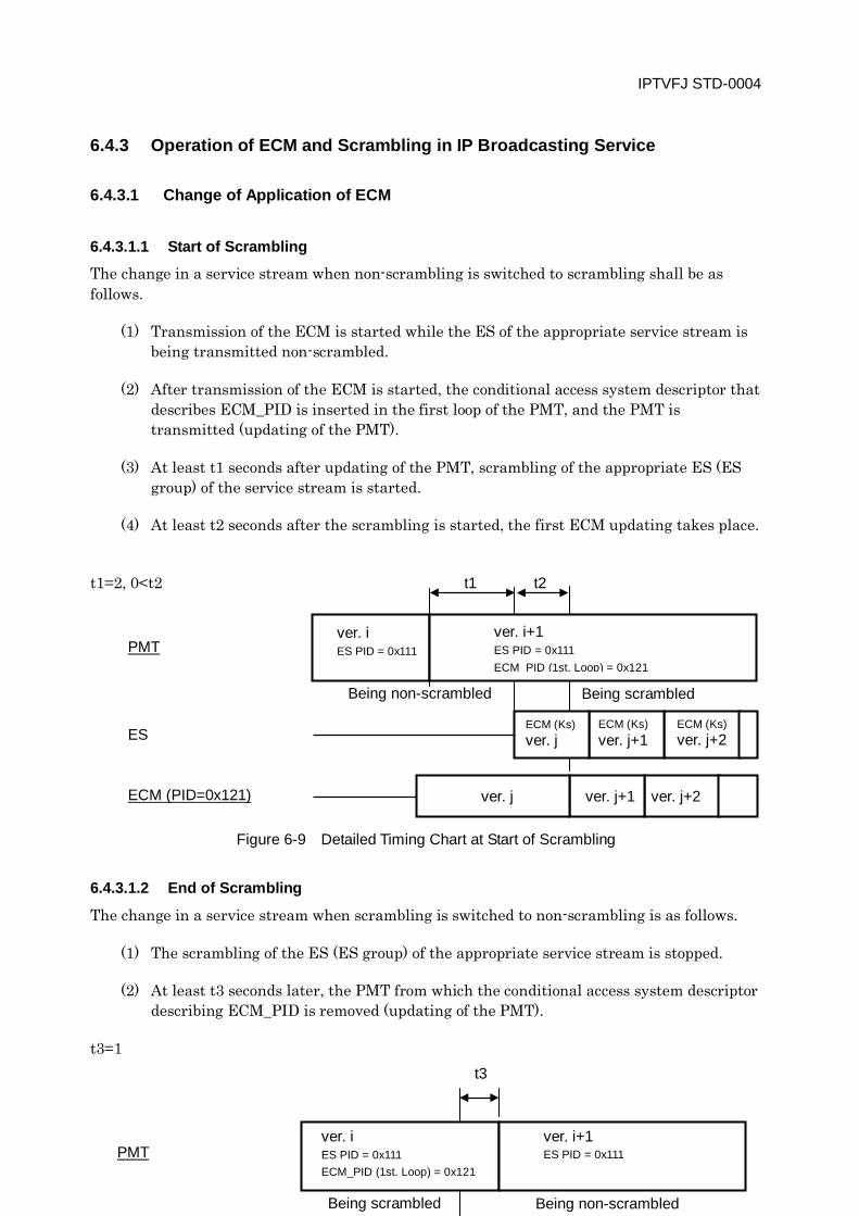
IPTVFJ STD-0004
—169—
6.4.3 Operation of ECM and Scrambling in IP Broadcasting Service
6.4.3.1 Change of Application of ECM
6.4.3.1.1 Start of Scrambling
The change in a service stream when non-scrambling is switched to scrambling shall be as follows.
(1) Transmission of the ECM is started while the ES of the appropriate service stream is being transmitted non-scrambled.
(2) After transmission of the ECM is started, the conditional access system descriptor that describes ECM_PID is inserted in the first loop of the PMT, and the PMT is transmitted (updating of the PMT).
(3) At least t1 seconds after updating of the PMT, scrambling of the appropriate ES (ES group) of the service stream is started.
(4) At least t2 seconds after the scrambling is started, the first ECM updating takes place.
t1=2, 0<t2
Figure 6-9 Detailed Timing Chart at Start of Scrambling
6.4.3.1.2 End of Scrambling
The change in a service stream when scrambling is switched to non-scrambling is as follows.
(1) The scrambling of the ES (ES group) of the appropriate service stream is stopped.
(2) At least t3 seconds later, the PMT from which the conditional access system descriptor describing ECM_PID is removed (updating of the PMT).
t3=1
PMT
ES
ECM (PID=0x121)
ver. i ES PID = 0x111
ver. i+1 ES PID = 0x111 ECM PID (1st. Loop) = 0x121
ver. j+2 ver. j+1 ver. j
t1 t2
Being scrambled Being non-scrambled
ECM (Ks) ver. j
ECM (Ks) ver. j+1
ECM (Ks) ver. j+2
t3
PMT ver. i ES PID = 0x111 ECM_PID (1st. Loop) = 0x121
ver. i+1 ES PID = 0x111
Being non-scrambled Being scrambled
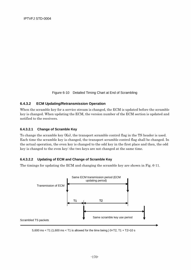
IPTVFJ STD-0004
-170-
Figure 6-10 Detailed Timing Chart at End of Scrambling
6.4.3.2 ECM Updating/Retransmission Operation When the scramble key for a service stream is changed, the ECM is updated before the scramble key is changed. When updating the ECM, the version number of the ECM section is updated and notified to the receivers.
6.4.3.2.1 Change of Scramble Key
To change the scramble key (Ks), the transport scramble control flag in the TS header is used. Each time the scramble key is changed, the transport scramble control flag shall be changed. In the actual operation, the even key is changed to the odd key in the first place and then, the odd key is changed to the even key: the two keys are not changed at the same time.
6.4.3.2.2 Updating of ECM and Change of Scramble Key
The timings for updating the ECM and changing the scramble key are shown in Fig. 6-11.
T2 T1
Transmission of ECM
Scrambled TS packets
Same ECM transmission period (ECM updating period)
Same scramble key use period
T2
5,600 ms < T1 (1,600 ms < T1 is allowed for the time being.) 0<T2, T1 + T2>10 s
T1
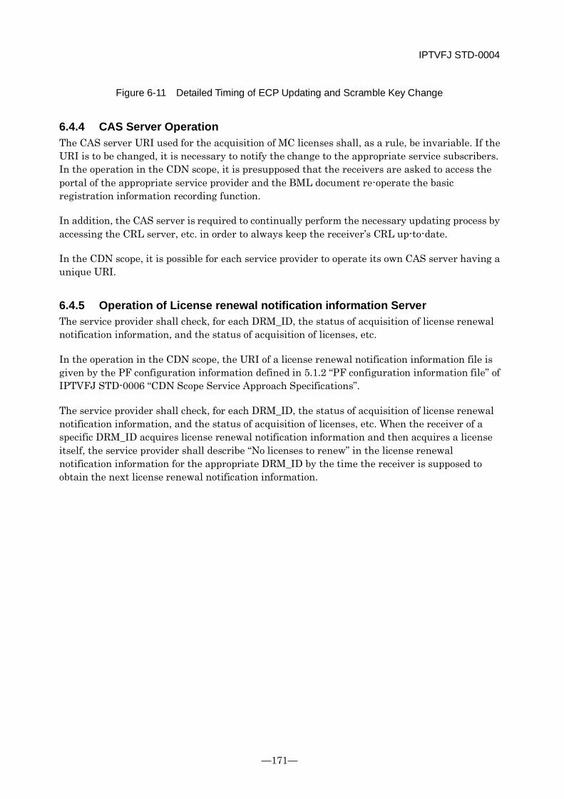
IPTVFJ STD-0004
—171—
Figure 6-11 Detailed Timing of ECP Updating and Scramble Key Change
6.4.4 CAS Server Operation The CAS server URI used for the acquisition of MC licenses shall, as a rule, be invariable. If the URI is to be changed, it is necessary to notify the change to the appropriate service subscribers. In the operation in the CDN scope, it is presupposed that the receivers are asked to access the portal of the appropriate service provider and the BML document re-operate the basic registration information recording function.
In addition, the CAS server is required to continually perform the necessary updating process by accessing the CRL server, etc. in order to always keep the receiver’s CRL up-to-date.
In the CDN scope, it is possible for each service provider to operate its own CAS server having a unique URI.
6.4.5 Operation of License renewal notification information Server The service provider shall check, for each DRM_ID, the status of acquisition of license renewal notification information, and the status of acquisition of licenses, etc.
In the operation in the CDN scope, the URI of a license renewal notification information file is given by the PF configuration information defined in 5.1.2 “PF configuration information file” of IPTVFJ STD-0006 “CDN Scope Service Approach Specifications”.
The service provider shall check, for each DRM_ID, the status of acquisition of license renewal notification information, and the status of acquisition of licenses, etc. When the receiver of a specific DRM_ID acquires license renewal notification information and then acquires a license itself, the service provider shall describe “No licenses to renew” in the license renewal notification information for the appropriate DRM_ID by the time the receiver is supposed to obtain the next license renewal notification information.

IPTVFJ STD-0004
-172-
Chapter 7 PSI/SI
Operation in General
7.1 Introduction
7.1.1 Preface The Electronic Program Guide (EPG) in the IP broadcasting service is implemented in accordance with the relevant ordinance and notification of the Ministry of Internal Affairs and Communications(MIC), Home Affairs, Posts and Telecommunications and the specifications defined by the Association of Radio Industries and Businesses (“ARIB”) in its standard specifications “Service Information for Digital Broadcasting” (ARIB STD-B10). In order to encourage positive use of said specifications, however, it was considered necessary to provide detailed specifications on the operation of PSI/SI. This is the reason why this section has been prepared.
The standard for transmission of transmission control information defined here is designed to enable each individual broadcaster using wire services to secure the flexibility of programming and the expandability of broadcasting for development of broadcast services in the future.
Each service provider shall transmit PSI/SI in accordance with these specifications.
It is desirable that the receiver should be able to receive PSI/SI signals which are transmitted in accordance with these specifications and that due care should be exercised to prevent the receiver from malfunctioning or getting into some other trouble when it receives unspecified signals, etc.
7.1.2 Purpose The purpose of this section is to define specifications for the transmission of PSI/SI in IP broadcasting in accordance with ARIB STD-B10 “Service Information for Digital Broadcasting”.
7.1.3 Scope These provisions apply to the structures of PSI and SI, signal types, basic data structures, the use of identifiers and transmission standards used in IP broadcasting.
These provisions have binding force, as described below:.
[On the receiving side] The specifications are intended primarily to specify the operation and transmission of PSI/SI in IP broadcasting: they do not absolutely require the receiver to be so implemented that it is compatible with the specified operation. It should be noted, however, that if the receiver
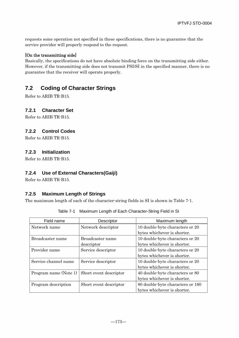
IPTVFJ STD-0004
—173—
requests some operation not specified in these specifications, there is no guarantee that the service provider will properly respond to the request.
[On the transmitting side] Basically, the specifications do not have absolute binding force on the transmitting side either. However, if the transmitting side does not transmit PSI/SI in the specified manner, there is no guarantee that the receiver will operate properly.
7.2 Coding of Character Strings Refer to ARIB TR-B15.
7.2.1 Character Set Refer to ARIB TR-B15.
7.2.2 Control Codes Refer to ARIB TR-B15.
7.2.3 Initialization Refer to ARIB TR-B15.
7.2.4 Use of External Characters(Gaiji) Refer to ARIB TR-B15.
7.2.5 Maximum Length of Strings The maximum length of each of the character-string fields in SI is shown in Table 7-1.
Table 7-1 Maximum Length of Each Character-String Field in SI
Field name Descriptor Maximum length Network name Network descriptor 10 double-byte characters or 20
bytes whichever is shorter. Broadcaster name Broadcaster name
descriptor 10 double-byte characters or 20 bytes whichever is shorter.
Provider name Service descriptor 10 double-byte characters or 20 bytes whichever is shorter.
Service channel name Service descriptor 10 double-byte characters or 20 bytes whichever is shorter.
Program name (Note 1) Short event descriptor 40 double-byte characters or 80 bytes whichever is shorter.
Program description Short event descriptor 80 double-byte characters or 160 bytes whichever is shorter.
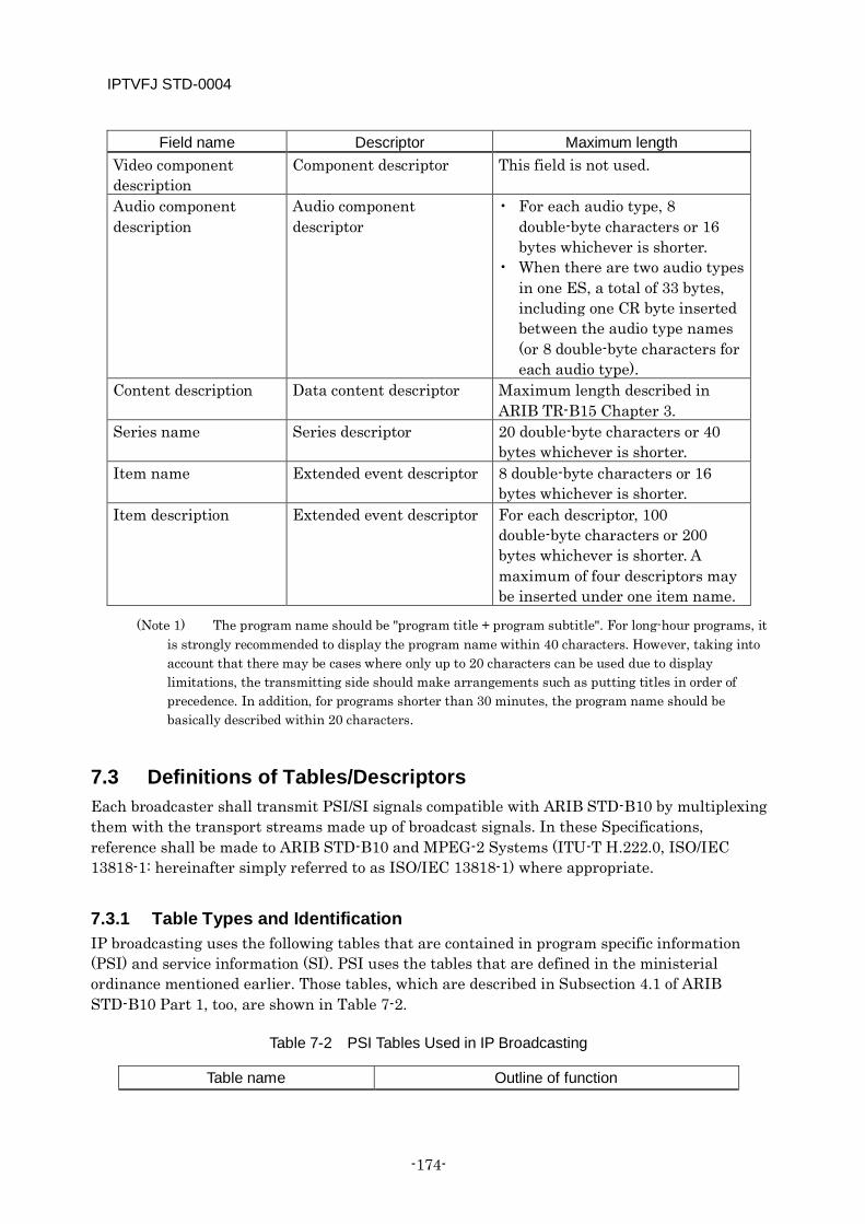
IPTVFJ STD-0004
-174-
Field name Descriptor Maximum length Video component description
Component descriptor This field is not used.
Audio component description
Audio component descriptor
• For each audio type, 8 double-byte characters or 16 bytes whichever is shorter.
• When there are two audio types in one ES, a total of 33 bytes, including one CR byte inserted between the audio type names (or 8 double-byte characters for each audio type).
Content description Data content descriptor Maximum length described in ARIB TR-B15 Chapter 3.
Series name Series descriptor 20 double-byte characters or 40 bytes whichever is shorter.
Item name Extended event descriptor 8 double-byte characters or 16 bytes whichever is shorter.
Item description Extended event descriptor For each descriptor, 100 double-byte characters or 200 bytes whichever is shorter. A maximum of four descriptors may be inserted under one item name.
(Note 1) The program name should be "program title + program subtitle". For long-hour programs, it is strongly recommended to display the program name within 40 characters. However, taking into account that there may be cases where only up to 20 characters can be used due to display limitations, the transmitting side should make arrangements such as putting titles in order of precedence. In addition, for programs shorter than 30 minutes, the program name should be basically described within 20 characters.
7.3 Definitions of Tables/Descriptors Each broadcaster shall transmit PSI/SI signals compatible with ARIB STD-B10 by multiplexing them with the transport streams made up of broadcast signals. In these Specifications, reference shall be made to ARIB STD-B10 and MPEG-2 Systems (ITU-T H.222.0, ISO/IEC 13818-1: hereinafter simply referred to as ISO/IEC 13818-1) where appropriate.
7.3.1 Table Types and Identification IP broadcasting uses the following tables that are contained in program specific information (PSI) and service information (SI). PSI uses the tables that are defined in the ministerial ordinance mentioned earlier. Those tables, which are described in Subsection 4.1 of ARIB STD-B10 Part 1, too, are shown in Table 7-2.
Table 7-2 PSI Tables Used in IP Broadcasting
Table name Outline of function
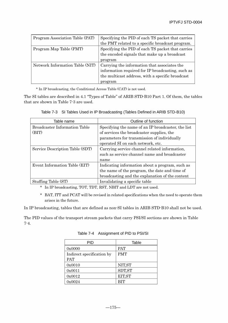
IPTVFJ STD-0004
—175—
Program Association Table (PAT) Specifying the PID of each TS packet that carries the PMT related to a specific broadcast program.
Program Map Table (PMT) Specifying the PID of each TS packet that carries the encoded signals that make up a broadcast program
Network Information Table (NIT) Carrying the information that associates the information required for IP broadcasting, such as the multicast address, with a specific broadcast program
* In IP broadcasting, the Conditional Access Table (CAT) is not used.
The SI tables are described in 4.1 “Types of Table” of ARIB STD-B10 Part 1. Of them, the tables that are shown in Table 7-3 are used.
Table 7-3 SI Tables Used in IP Broadcasting (Tables Defined in ARIB STD-B10)
Table name Outline of function Broadcaster Information Table (BIT)
Specifying the name of an IP broadcaster, the list of services the broadcaster supplies, the parameters for transmission of individually operated SI on each network, etc.
Service Description Table (SDT) Carrying service channel related information, such as service channel name and broadcaster name
Event Information Table (EIT) Indicating information about a program, such as the name of the program, the date and time of broadcasting and the explanation of the content
Stuffing Table (ST) Invalidating a specific table * In IP broadcasting, TOT, TDT, RST, NBIT and LDT are not used.
* BAT, ITT and PCAT will be revised in related specifications when the need to operate them arises in the future.
In IP broadcasting, tables that are defined as non-SI tables in ARIB STD-B10 shall not be used.
The PID values of the transport stream packets that carry PSI/SI sections are shown in Table 7-4.
Table 7-4 Assignment of PID to PSI/SI
PID Table 0x0000 PAT Indirect specification by PAT
PMT
0x0010 NIT,ST 0x0011 SDT,ST 0x0012 EIT,ST 0x0024 BIT
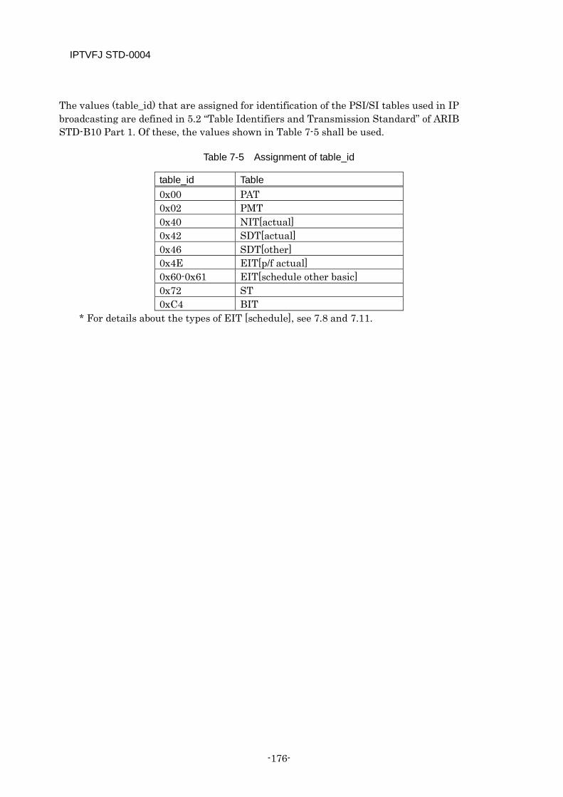
IPTVFJ STD-0004
-176-
The values (table_id) that are assigned for identification of the PSI/SI tables used in IP broadcasting are defined in 5.2 “Table Identifiers and Transmission Standard” of ARIB STD-B10 Part 1. Of these, the values shown in Table 7-5 shall be used.
Table 7-5 Assignment of table_id
table_id Table 0x00 PAT 0x02 PMT 0x40 NIT[actual] 0x42 SDT[actual] 0x46 SDT[other] 0x4E EIT[p/f actual] 0x60-0x61 EIT[schedule other basic] 0x72 ST 0xC4 BIT
* For details about the types of EIT [schedule], see 7.8 and 7.11.
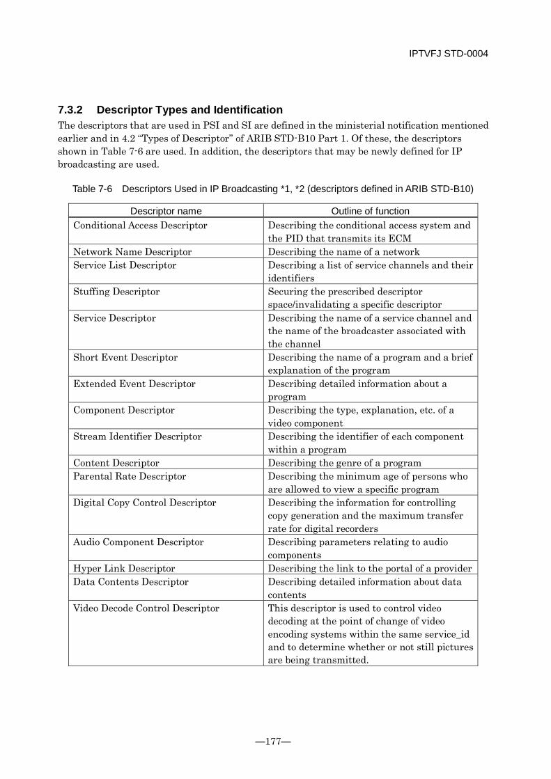
IPTVFJ STD-0004
—177—
7.3.2 Descriptor Types and Identification The descriptors that are used in PSI and SI are defined in the ministerial notification mentioned earlier and in 4.2 “Types of Descriptor” of ARIB STD-B10 Part 1. Of these, the descriptors shown in Table 7-6 are used. In addition, the descriptors that may be newly defined for IP broadcasting are used.
Table 7-6 Descriptors Used in IP Broadcasting *1, *2 (descriptors defined in ARIB STD-B10)
Descriptor name Outline of function Conditional Access Descriptor Describing the conditional access system and
the PID that transmits its ECM Network Name Descriptor Describing the name of a network Service List Descriptor Describing a list of service channels and their
identifiers Stuffing Descriptor Securing the prescribed descriptor
space/invalidating a specific descriptor Service Descriptor Describing the name of a service channel and
the name of the broadcaster associated with the channel
Short Event Descriptor Describing the name of a program and a brief explanation of the program
Extended Event Descriptor Describing detailed information about a program
Component Descriptor Describing the type, explanation, etc. of a video component
Stream Identifier Descriptor Describing the identifier of each component within a program
Content Descriptor Describing the genre of a program Parental Rate Descriptor Describing the minimum age of persons who
are allowed to view a specific program Digital Copy Control Descriptor Describing the information for controlling
copy generation and the maximum transfer rate for digital recorders
Audio Component Descriptor Describing parameters relating to audio components
Hyper Link Descriptor Describing the link to the portal of a provider Data Contents Descriptor Describing detailed information about data
contents Video Decode Control Descriptor This descriptor is used to control video
decoding at the point of change of video encoding systems within the same service_id and to determine whether or not still pictures are being transmitted.
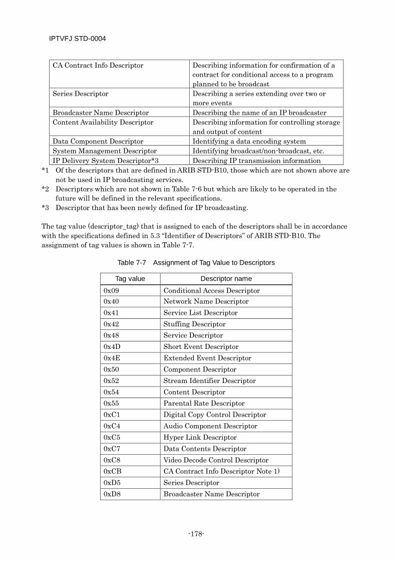
IPTVFJ STD-0004
-178-
CA Contract Info Descriptor Describing information for confirmation of a contract for conditional access to a program planned to be broadcast
Series Descriptor Describing a series extending over two or more events
Broadcaster Name Descriptor Describing the name of an IP broadcaster Content Availability Descriptor Describing information for controlling storage
and output of content Data Component Descriptor Identifying a data encoding system System Management Descriptor Identifying broadcast/non-broadcast, etc. IP Delivery System Descriptor*3 Describing IP transmission information
*1 Of the descriptors that are defined in ARIB STD-B10, those which are not shown above are not be used in IP broadcasting services.
*2 Descriptors which are not shown in Table 7-6 but which are likely to be operated in the future will be defined in the relevant specifications.
*3 Descriptor that has been newly defined for IP broadcasting. The tag value (descriptor_tag) that is assigned to each of the descriptors shall be in accordance with the specifications defined in 5.3 “Identifier of Descriptors” of ARIB STD-B10. The assignment of tag values is shown in Table 7-7.
Table 7-7 Assignment of Tag Value to Descriptors
Tag value Descriptor name
0x09 Conditional Access Descriptor 0x40 Network Name Descriptor 0x41 Service List Descriptor 0x42 Stuffing Descriptor 0x48 Service Descriptor 0x4D Short Event Descriptor 0x4E Extended Event Descriptor 0x50 Component Descriptor 0x52 Stream Identifier Descriptor 0x54 Content Descriptor 0x55 Parental Rate Descriptor 0xC1 Digital Copy Control Descriptor 0xC4 Audio Component Descriptor 0xC5 Hyper Link Descriptor 0xC7 Data Contents Descriptor 0xC8 Video Decode Control Descriptor 0xCB CA Contract Info Descriptor Note 1) 0xD5 Series Descriptor 0xD8 Broadcaster Name Descriptor
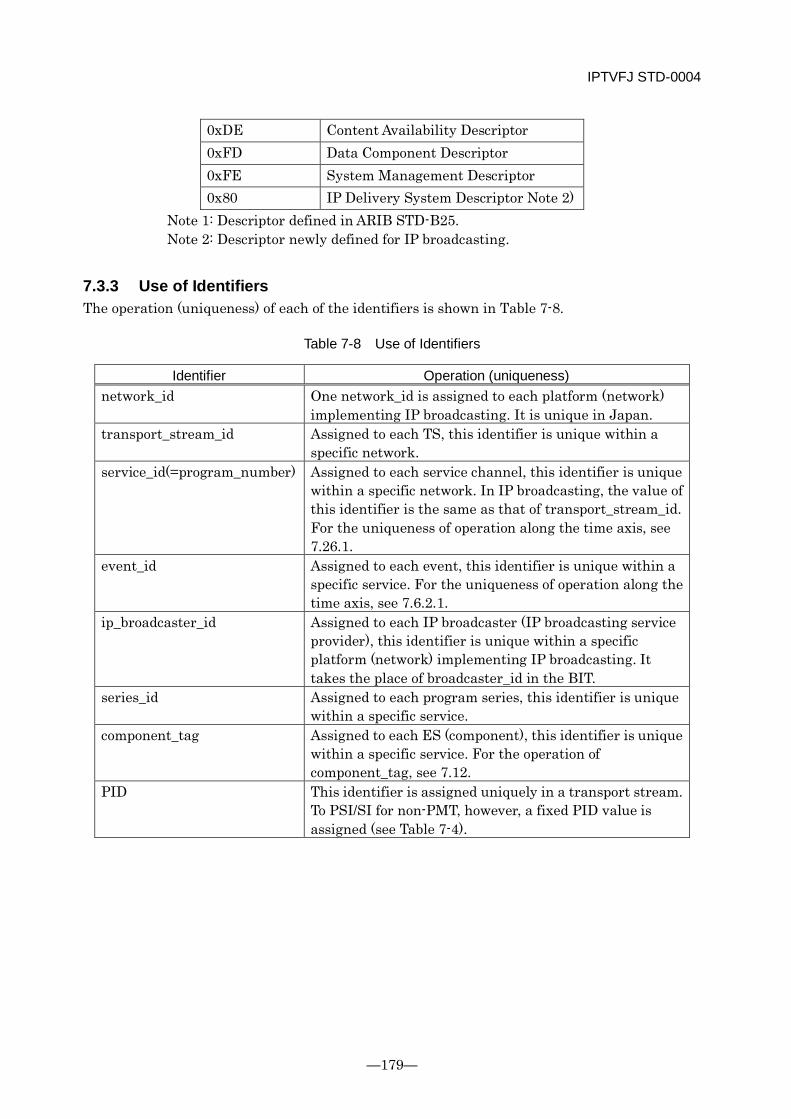
IPTVFJ STD-0004
—179—
0xDE Content Availability Descriptor 0xFD Data Component Descriptor 0xFE System Management Descriptor 0x80 IP Delivery System Descriptor Note 2)
Note 1: Descriptor defined in ARIB STD-B25. Note 2: Descriptor newly defined for IP broadcasting.
7.3.3 Use of Identifiers The operation (uniqueness) of each of the identifiers is shown in Table 7-8.
Table 7-8 Use of Identifiers
Identifier Operation (uniqueness) network_id One network_id is assigned to each platform (network)
implementing IP broadcasting. It is unique in Japan. transport_stream_id
Assigned to each TS, this identifier is unique within a specific network.
service_id(=program_number)
Assigned to each service channel, this identifier is unique within a specific network. In IP broadcasting, the value of this identifier is the same as that of transport_stream_id. For the uniqueness of operation along the time axis, see 7.26.1.
event_id
Assigned to each event, this identifier is unique within a specific service. For the uniqueness of operation along the time axis, see 7.6.2.1.
ip_broadcaster_id
Assigned to each IP broadcaster (IP broadcasting service provider), this identifier is unique within a specific platform (network) implementing IP broadcasting. It takes the place of broadcaster_id in the BIT.
series_id Assigned to each program series, this identifier is unique within a specific service.
component_tag Assigned to each ES (component), this identifier is unique within a specific service. For the operation of component_tag, see 7.12.
PID This identifier is assigned uniquely in a transport stream. To PSI/SI for non-PMT, however, a fixed PID value is assigned (see Table 7-4).

IPTVFJ STD-0004
-180-
7.4 Use of Items Common to All Tables
7.4.1 Use of version_number
7.4.1.1 Assignment of version_number and Securing of Identical version_number A version_number is assigned independently to each sub-table. Namely, the NIT and BIT that are transmitted by each transport stream within a specific network are given the same version_number in all the transport streams as long as table_id and table_id_extension are the same in value. On the other hand, the version_number assigned to the SDT [actual] has nothing to do with the version_number assigned to the SDT [other].
7.4.1.2 Change Timing There are cases in which each of the "other" tables transmitted by a transport SI-exclusive TS is updated somewhat later than each of the "actual" tables transmitted by an ordinary transport stream. (This is because the SI-exclusive TS requires extra time for processing and transmitting SI.)
When SDT is updated There is the possibility that the SDT [other] will be updated later than the SDT [actual].
When EIT is updated When the content of description in the EIT is changed due to flexible program schedule, etc., there is the possibility that the EIT [schedule other] will be changed later than the EIT [p/f actual].
7.4.1.3 Version Change Ordinarily, the version_number is incremented by 1 each time the current version is updated or changed. It should be noted, however, that under extraordinary circumstances, such as an equipment failure, the version_number might be incremented by 2 or more (not 1) or changed without any modification to the content of the current version.
7.4.1.4 Section Version Management The same version_number is assigned to the sections with the same table_id and table_id_extension within a TS. version_number should not differ among the sections with the same table_id and table_id_extension.
7.4.2 Use of current_next_indicator All the tables shall be transmitted with current_next_indicator set to “1”. Any tables with the value of current_next_indicator being 0 shall not be transmitted.
If any table with the value “0” is transmitted, the receiving side shall invalidate the table.
IPTVFJ STD-0004
—181—
7.4.3 Use of running_status The SDT and EIT shall be transmitted with all the values of running_status being undefined (0x0).
If they are transmitted with some other values set, the receiving side shall assume the values to be 0x0.
7.4.4 Use of "reserved" and reserved_future_use Items This item shall be transmitted with all the bits set to “1”.
The receiving side shall ignore this item no matter what value is set in it.
7.4.5 Scrambling In IP broadcasting, none of the tables that are defined in these Specifications must be scrambled.
7.5 Change of SI Any service provider may change the content of SI as required. However, since doing that carelessly can confuse the viewer, attention should be paid to the following points.
As a rule, the EIT information relating to recording control and viewing control should not be changed once it is defined. This is to prevent trouble with the recording function, etc. which can occur if there is a discrepancy between the receiver condition during reservation and the receiver condition during an actual broadcast.
The SDT information relating to recording control and viewing control is used interlocked with the EIT control information. As a rule, therefore, it should not be changed. If it is absolutely necessary to change the SDT information, it has to be so changed that the compatibility with the content of the EIT [schedule] is maintained.
Concerning the information that helps the viewer grasp the content of a program, such as the program name and program description, it should, as far as possible, be kept unchanged once it is defined.
7.6 Definitions of Services and Events
7.6.1 Definitions of Services and Service Types A service is a so-called service channel. It is defined as “sequence of programs under the control of a broadcaster which can be broadcast as part of a schedule” (quoted from 3.1 “Definitions” of ARIB STD-B10 Part 2).
It is assumed that a service is defined at the time when its service_id is described in the service list descriptor of the NIT. A service which is described in the service descriptor of the NIT
IPTVFJ STD-0004
-182-
should be always described in the SDT too. Therefore, if there is a service which has been described in the NIT service descriptor but which does not exist in the SDT, it may be assumed that the service is in a period of transition, that is, the service is about to be deleted or added. Even in this case, the service should be included in the scope of channel selection.
It should be noted that even a program whose service is not defined in the NIT may be transmitted. In this case, the program that has not been defined in the NIT must have been entered in the PAT. This program is not included in the scope of channel selection. As programs whose service is not defined in the NIT, there are, for example, test broadcasts. These programs do not permit direct channel selection by input of a channel number, etc.
To indicate the type of a specific service, one service_type must be assigned to the service. In IP broadcasting, the following service types shall be operated.
Digital TV service
A service which contains at least one video stream and which is intended mainly for the viewer to view the video stream(s)
Promotion video service
A service for publicizing the content of a program or service
Video service for adults
A video service providing only programs having a parental rate set on for viewers. In this service, unless a parental rate is preset in the receiver and the preset rate is 20 or more (there are no upper bounds), the receiver neither presents any programs nor displays any program information/channel information by means of the EPG, etc.
7.6.2 Definition of Events In 3.1 “Definitions” of ARIB STD-B10 Part 2, an event is defined as follows. “Grouping of elementary broadcast data streams with a with a defined start and end time belonging to a common service.” Since the term “program” has not been defined, what event is defined in the content of a broadcast is left to the judgment of each individual broadcaster.
It is assumed that an event is established at the time event_id appears in the event loop of the EIT. In IP broadcasting, there is more than one EIT, in commonly operated SI and in SI for independent operation. The event becomes effective when any one of them is described regardless of whether it is actual or other.
The basic concepts of event establishment are shown below.
No events shall be established during the period of service suspension. Therefore, during digital TV service, every event contains at least one video stream and one audio stream.
It is not always necessary to establish consecutive events throughout a service broadcast. Even during the service broadcast (i.e., when there is some component in the program), there may be a period in which no event exists.
IPTVFJ STD-0004
—183—
It is not allowed to establish events whose broadcasting times overlap within the same service.
The duration of any event that can be established shall be a maximum of 48 hours and a minimum of one minute. It should be noted, however, that under unavoidable circumstances the minimum duration may be less than one minute. In a case like this, it is desirable that as far as possible, the event should be so planned that its duration becomes one minute by, for example, integrating it with the preceding or succeeding event or setting the duration of the event as a period in which no events exist.
There are cases in which an event needs to be changed due to an unexpected incident or accident, etc. (See 7.17 “Change of programmed event”.) In IP broadcasting, which does not always presuppose flexible program scheduling, it can happen that start_time and duration of an event need to be changed or that an event becomes suspended. Although any decision on programming should be reflected in the EIT without delay, under certain circumstances an event program might remain unsettled for many hours.
When establishing an event, consideration should be given to the following points.
Establishing an event means not only deciding on a broadcast channel and broadcasting time and assigning event_id but also defining the “content of the broadcast.” From the standpoint of the viewer, the content of the program itself imagined from the program name and the content of program description is considered an established event. Therefore, as far as possible, broadcasting programs having different contents under the same event_id should be avoided.
However, concerning how to allocate events, each individual broadcaster should judge it in light of the definition of event and the basic concept of event establishment. (For example, a broadcaster might want to broadcast a series of movies of the same genre with the same event_id within a fixed time frame of movie broadcasting.)
7.6.2.1 Reuse of event_id (Uniqueness of Time Axis) For the event_id that is described in an EIT being transmitted, the same value must not be assigned to different events within the same service. Besides, even after the event description is erased and the value of event_id disappears from the EIT at the end or abortion of the event, the same value must neither be assigned to a different event nor be described in the EIT within 24 hours from the event ending time that is determined from the event start_time and duration described in the EIT (if the start_time and duration of the preceding event have been changed as a result of flexible program scheduling, etc., the event ending time before the change or the event ending time during the change or the event ending time after the change whichever is the latest.)
Explanation:
The value of event_id described in the EIT cannot be used for more than one event within the same service since event_id itself is unique within the service_id. However, when the ending time of an event has elapsed, the value of event_id assigned to that event disappears from the EIT, making it possible to assign the same value to a different event after a certain time. If, however, the same value is assigned to a different event soon after it disappears from the EIT, it
IPTVFJ STD-0004
-184-
would become considerably difficult for the receiving side to determine whether or not it is due to a change of events. In particular, if the preceding event is aborted and the event_id value assigned to that event is used for the current event with no time lag, it can cause the reservation operation to fail. To prevent that, it was decided to define the following specifications.
For the purpose of explanation of the specifications, a few examples are given below.
[Case 1] Assume that Event A having event_id = 0x0010, start_time = Aug. 20, 19:00 and duration = 1 hour is described in an EIT [schedule] on August 13. Then, the event will start at 19:00 on August 20 and end at 20:00 on the same day. At that ending time, the description of Event A will disappear from the EIT [p/f] and the EIT [schedule]. Now, assume again that the event_id (= 0x0010) used for Event A is to be used for Event B after the description of Event A disappears. Then, it is 20:00 on August 21 at the earliest that Event B can be described in the EIT since the description is prohibited for 24 hours after the ending time of Event A. What should be noted here is that information about Event B cannot be described in the EIT until 20:00 on August 21, regardless of the start_time and duration of Event B.
[Case 2] Assume that Event A mentioned in Case 1 is not broadcast and that the description thereof disappears from the EIT [schedule] on August 16, four days before the scheduled date. Even in this case, Event B having the same event_id as Event A cannot be described in the EIT until 20:00 on August 21 since the 24-hour embargo is counted from the scheduled ending time of Event A.
[Case 3] Assume that Event A mentioned in Case 1 undergoes a change in start_time/duration due to flexible programming, etc. and that the description thereof in the EIT is changed accordingly. In this case, the time of 24-hour embargo is counted from the ending time before the change or the ending time after the change or the ending time in the middle of the change (if the change is made more than once) whichever is the latest. Assume, for example, that Event A undergoes the following changes:
start_time = 19:00, Aug. 20; duration = 1 hour ↓ start_time = 20:00, Aug. 20; duration = 2 hours ↓ start_time = 20:00, Aug. 20; duration = 1 hour
Then, the latest ending time is marked when start_time = 20:00, Aug. 20 and duration = 2 hours. Although Event A actually ends at 21:00 of August 20, Event B cannot be described in the EIT until 22:00 on August 21 — 24 hours after 22:00 of August 20.
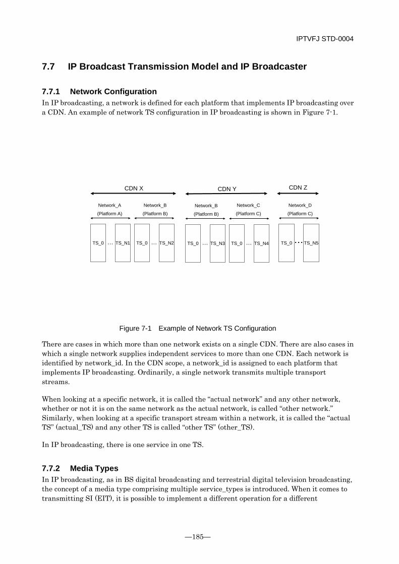
IPTVFJ STD-0004
—185—
7.7 IP Broadcast Transmission Model and IP Broadcaster
7.7.1 Network Configuration In IP broadcasting, a network is defined for each platform that implements IP broadcasting over a CDN. An example of network TS configuration in IP broadcasting is shown in Figure 7-1.
CDN X
…
Network_A
(Platform A)
TS_0 TS_N1 …TS_0 TS_N2 …TS_0 TS_N3
Network_B
(Platform B)
Network_B
(Platform B)
CDN Y
・・・
Network_D
(Platform C)
TS_0 TS_N5…TS_0 TS_N4
Network_C
(Platform C)
CDN Z
Figure 7-1 Example of Network TS Configuration
There are cases in which more than one network exists on a single CDN. There are also cases in which a single network supplies independent services to more than one CDN. Each network is identified by network_id. In the CDN scope, a network_id is assigned to each platform that implements IP broadcasting. Ordinarily, a single network transmits multiple transport streams.
When looking at a specific network, it is called the “actual network” and any other network, whether or not it is on the same network as the actual network, is called “other network.” Similarly, when looking at a specific transport stream within a network, it is called the “actual TS” (actual_TS) and any other TS is called “other TS” (other_TS).
In IP broadcasting, there is one service in one TS.
7.7.2 Media Types In IP broadcasting, as in BS digital broadcasting and terrestrial digital television broadcasting, the concept of a media type comprising multiple service_types is introduced. When it comes to transmitting SI (EIT), it is possible to implement a different operation for a different
IPTVFJ STD-0004
-186-
service_type. However, it is undesirable to define a new operational group each time a new service_type is introduced in the future. Therefore, an operational group called a media type that puts together multiple service_types is provided. The correspondence between media type and service_types and the service_types operated in IP broadcasting are shown in Table 7-9.
Table 7-9 Correspondence between media_type and service_types
Media type (media_type) Corresponding service_type Operation in IP
broadcasting Value Meaning Value Meaning
‘01’ TV type 0x01 Digital TV service 0xA5 Promotion video service 0x80 Video service for adults
Note: There is the possibility that service_types other than those shown above will be added in the future. In that case, their operation shall be defined separately. Even the service_types that are operated in BS digital broadcasting, wide-band CS digital broadcasting and terrestrial digital broadcasting are not always subject to the same operational specifications.
Any service_type must belong to a single media type. When a new service_type is added in the future, it shall be made to correspond to one of the three media types (TV type, audio type and data type). The information shown in the above table is not transmitted as a parameter. Therefore, the service information (SI) about the service of the newly added service_type is not accessible to any receiver that is not informed of said service_type. However, since it is presupposed that any receiver will not access a service of unknown service_type, there is no problem even if the receiver cannot receive the SI about such a service.
In the case of a receiver which is developed after the addition of a new service_type, it is capable of receiving the SI about the service of the new service_type since it is informed of the correspondence between the media type and the service_type. It should be noted that the correspondence that is once defined is not changed.
The media type has been worked out with special consideration given to the receiver operation in the presentation of program information and the selection of a channel. Therefore, the receiver can use the above media type when processing the TV type. When defining a new service_type, by contrast, it must be assigned to the proper media type with due consideration given to the media concerned.
7.7.3 Operation of IP Broadcaster The IP broadcaster is the unit of TS within a network in IP broadcasting. An IP broadcaster is assigned to each service provider implementing IP broadcasting within a network and is identified by broadcaster_id in the BIT described later. An example of the relationship between IP broadcaster and TS is shown in Figure 7-2.
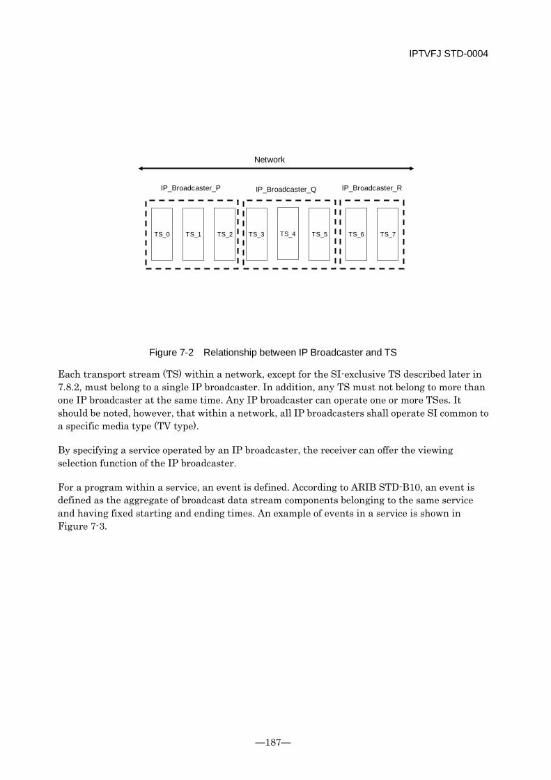
IPTVFJ STD-0004
—187—
Network
IP_Broadcaster_P
TS_0 TS_1 TS_2 TS_3 TS_4 TS_5 TS_6 TS_7
IP_Broadcaster_Q IP_Broadcaster_R
Figure 7-2 Relationship between IP Broadcaster and TS
Each transport stream (TS) within a network, except for the SI-exclusive TS described later in 7.8.2, must belong to a single IP broadcaster. In addition, any TS must not belong to more than one IP broadcaster at the same time. Any IP broadcaster can operate one or more TSes. It should be noted, however, that within a network, all IP broadcasters shall operate SI common to a specific media type (TV type).
By specifying a service operated by an IP broadcaster, the receiver can offer the viewing selection function of the IP broadcaster.
For a program within a service, an event is defined. According to ARIB STD-B10, an event is defined as the aggregate of broadcast data stream components belonging to the same service and having fixed starting and ending times. An example of events in a service is shown in Figure 7-3.
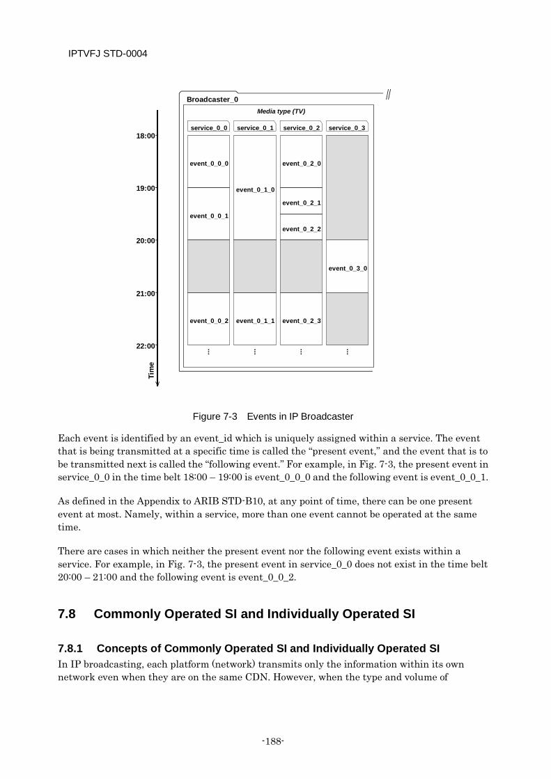
IPTVFJ STD-0004
-188-
Figure 7-3 Events in IP Broadcaster
Each event is identified by an event_id which is uniquely assigned within a service. The event that is being transmitted at a specific time is called the “present event,” and the event that is to be transmitted next is called the “following event.” For example, in Fig. 7-3, the present event in service_0_0 in the time belt 18:00 – 19:00 is event_0_0_0 and the following event is event_0_0_1.
As defined in the Appendix to ARIB STD-B10, at any point of time, there can be one present event at most. Namely, within a service, more than one event cannot be operated at the same time.
There are cases in which neither the present event nor the following event exists within a service. For example, in Fig. 7-3, the present event in service_0_0 does not exist in the time belt 20:00 – 21:00 and the following event is event_0_0_2.
7.8 Commonly Operated SI and Individually Operated SI
7.8.1 Concepts of Commonly Operated SI and Individually Operated SI In IP broadcasting, each platform (network) transmits only the information within its own network even when they are on the same CDN. However, when the type and volume of
Broadcaster_0 Media type (TV)
Tim
e
18:00
19:00
20:00
21:00
22:00
service_0_0
event_0_0_0
event_0_0_1
event_0_0_2
service_0_1
event_0_1_0
event_0_1_1
service_0_2
event_0_2_0
event_0_2_1
event_0_2_3
service_0_3
event_0_3_0
event_0_2_2
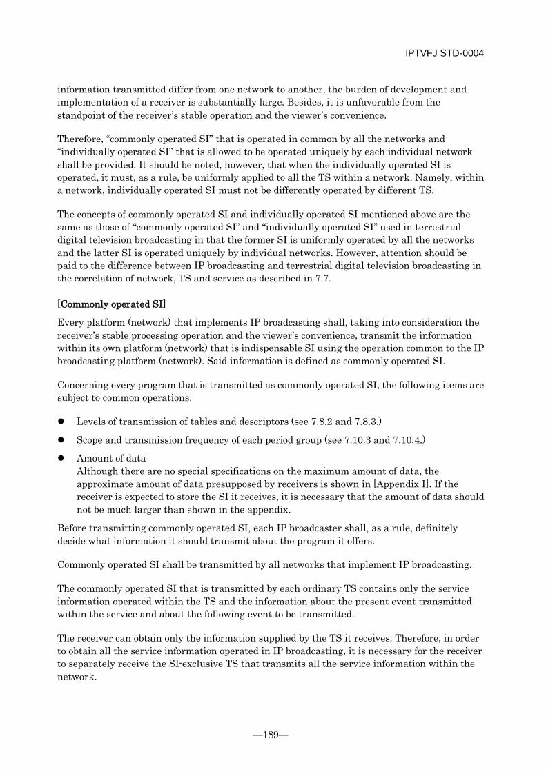
IPTVFJ STD-0004
—189—
information transmitted differ from one network to another, the burden of development and implementation of a receiver is substantially large. Besides, it is unfavorable from the standpoint of the receiver’s stable operation and the viewer’s convenience.
Therefore, “commonly operated SI” that is operated in common by all the networks and “individually operated SI” that is allowed to be operated uniquely by each individual network shall be provided. It should be noted, however, that when the individually operated SI is operated, it must, as a rule, be uniformly applied to all the TS within a network. Namely, within a network, individually operated SI must not be differently operated by different TS.
The concepts of commonly operated SI and individually operated SI mentioned above are the same as those of “commonly operated SI” and “individually operated SI” used in terrestrial digital television broadcasting in that the former SI is uniformly operated by all the networks and the latter SI is operated uniquely by individual networks. However, attention should be paid to the difference between IP broadcasting and terrestrial digital television broadcasting in the correlation of network, TS and service as described in 7.7.
[Commonly operated SI]
Every platform (network) that implements IP broadcasting shall, taking into consideration the receiver’s stable processing operation and the viewer’s convenience, transmit the information within its own platform (network) that is indispensable SI using the operation common to the IP broadcasting platform (network). Said information is defined as commonly operated SI.
Concerning every program that is transmitted as commonly operated SI, the following items are subject to common operations.
Levels of transmission of tables and descriptors (see 7.8.2 and 7.8.3.)
Scope and transmission frequency of each period group (see 7.10.3 and 7.10.4.)
Amount of data Although there are no special specifications on the maximum amount of data, the approximate amount of data presupposed by receivers is shown in [Appendix I]. If the receiver is expected to store the SI it receives, it is necessary that the amount of data should not be much larger than shown in the appendix.
Before transmitting commonly operated SI, each IP broadcaster shall, as a rule, definitely decide what information it should transmit about the program it offers.
Commonly operated SI shall be transmitted by all networks that implement IP broadcasting.
The commonly operated SI that is transmitted by each ordinary TS contains only the service information operated within the TS and the information about the present event transmitted within the service and about the following event to be transmitted.
The receiver can obtain only the information supplied by the TS it receives. Therefore, in order to obtain all the service information operated in IP broadcasting, it is necessary for the receiver to separately receive the SI-exclusive TS that transmits all the service information within the network.
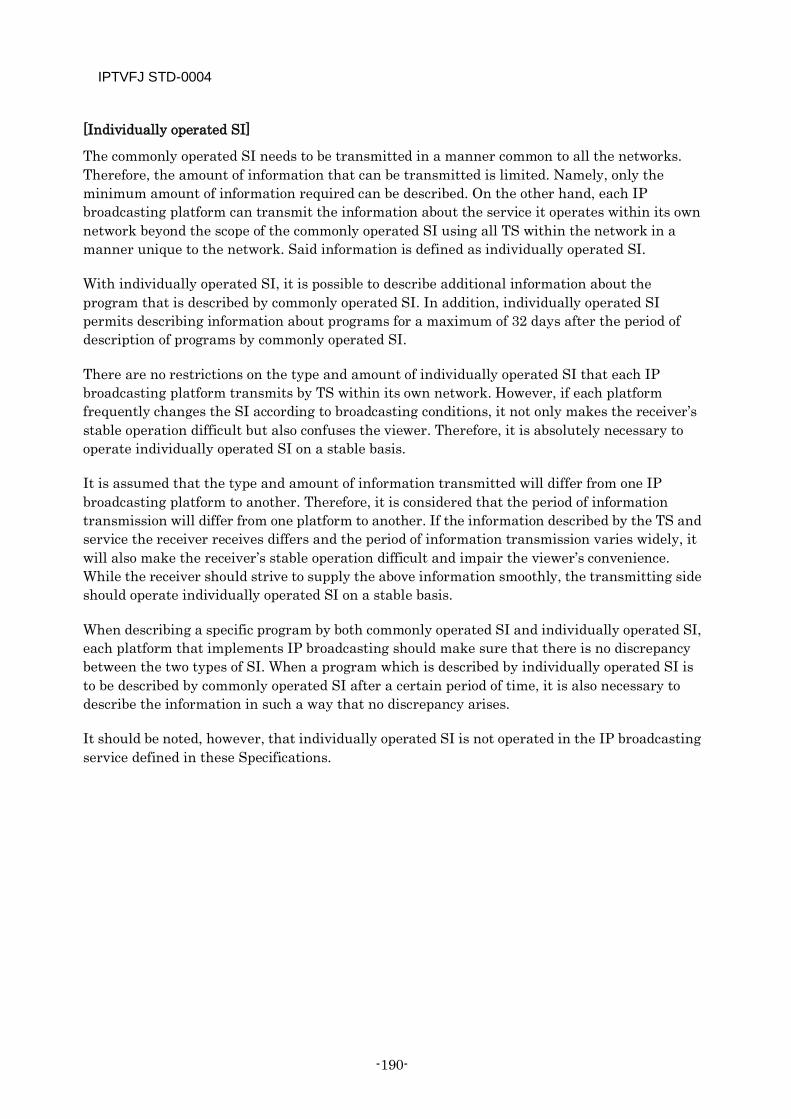
IPTVFJ STD-0004
-190-
[Individually operated SI]
The commonly operated SI needs to be transmitted in a manner common to all the networks. Therefore, the amount of information that can be transmitted is limited. Namely, only the minimum amount of information required can be described. On the other hand, each IP broadcasting platform can transmit the information about the service it operates within its own network beyond the scope of the commonly operated SI using all TS within the network in a manner unique to the network. Said information is defined as individually operated SI.
With individually operated SI, it is possible to describe additional information about the program that is described by commonly operated SI. In addition, individually operated SI permits describing information about programs for a maximum of 32 days after the period of description of programs by commonly operated SI.
There are no restrictions on the type and amount of individually operated SI that each IP broadcasting platform transmits by TS within its own network. However, if each platform frequently changes the SI according to broadcasting conditions, it not only makes the receiver’s stable operation difficult but also confuses the viewer. Therefore, it is absolutely necessary to operate individually operated SI on a stable basis.
It is assumed that the type and amount of information transmitted will differ from one IP broadcasting platform to another. Therefore, it is considered that the period of information transmission will differ from one platform to another. If the information described by the TS and service the receiver receives differs and the period of information transmission varies widely, it will also make the receiver’s stable operation difficult and impair the viewer’s convenience. While the receiver should strive to supply the above information smoothly, the transmitting side should operate individually operated SI on a stable basis.
When describing a specific program by both commonly operated SI and individually operated SI, each platform that implements IP broadcasting should make sure that there is no discrepancy between the two types of SI. When a program which is described by individually operated SI is to be described by commonly operated SI after a certain period of time, it is also necessary to describe the information in such a way that no discrepancy arises.
It should be noted, however, that individually operated SI is not operated in the IP broadcasting service defined in these Specifications.
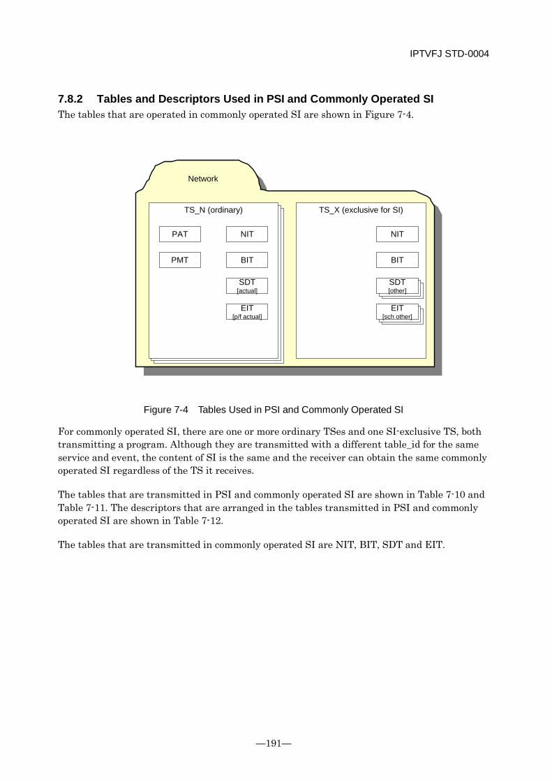
IPTVFJ STD-0004
—191—
7.8.2 Tables and Descriptors Used in PSI and Commonly Operated SI The tables that are operated in commonly operated SI are shown in Figure 7-4.
TS_NTS_N (ordinary)
NIT
BIT
SDT[actual]
EIT[p/f actual]
PAT
PMT
TS_X (exclusive for SI)
NIT
BIT
SDT[other]
EIT[sch other]
Network
Figure 7-4 Tables Used in PSI and Commonly Operated SI
For commonly operated SI, there are one or more ordinary TSes and one SI-exclusive TS, both transmitting a program. Although they are transmitted with a different table_id for the same service and event, the content of SI is the same and the receiver can obtain the same commonly operated SI regardless of the TS it receives.
The tables that are transmitted in PSI and commonly operated SI are shown in Table 7-10 and Table 7-11. The descriptors that are arranged in the tables transmitted in PSI and commonly operated SI are shown in Table 7-12.
The tables that are transmitted in commonly operated SI are NIT, BIT, SDT and EIT.

IPTVFJ STD-0004
-192-
[Ordinary TS]
The NIT is a table described for each IP broadcasting network. In IP broadcasting, only the sub-table (NIT [actual]) of the actual network is described. This table is transmitted by each TS.
The BIT is a table described for an IP broadcaster operated within each IP broadcasting network. Only one BIT is arranged for each IP broadcasting network. Like the NIT, this table is transmitted by each TS.
The SDT is a table described for a service operated in IP broadcasting. Only one sub-table (SDT [actual]) of the actual TS is arranged and transmitted.
The EIT is a table described for an event contained in a service operated in IP broadcasting. Concerning EIT [p/f], only the same number of sub-tables (EIT [p/f actual]) of the actual TS service as the number of services, that is, one sub-table, is arranged and transmitted. EIT [schedule actual]) is not transmitted.
[SI-exclusive TS]
The NIT and BIT are exactly the same as those which are arranged and transmitted by ordinary TS.
Concerning the SDT, the same number of tables (SDT [other]) about the services transmitted by ordinary TS as the TS are arranged and transmitted. Although the tables described have different table_id, the contents of the tables for the same service shall be the same.
Concerning the EIT, too, the same number of tables (EIT [other]) about the events operated within the TS as the TS services are arranged and transmitted. Note, however, that EIT [p/f other] is not transmitted: only the EIT [schedule other] is transmitted.
Thus, the table relating to the present or following event (EIT [p/f]) and the table relating to an event scheduled to be transmitted in a certain period of time (EIT [schedule]) are not transmitted by the same TS. These two tables differ in transmission route and table_id.
It is assumed that the period of the event to be described in EIT [schedule] differs according to the media type. However, as long as the media type is the same, the events described in TS are the same. In IP broadcasting, the events to be described are only those of TV type.
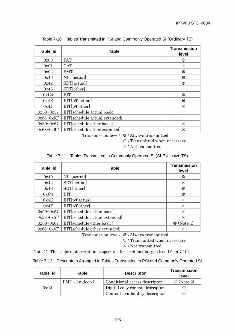
IPTVFJ STD-0004
—193—
Table 7-10 Tables Transmitted in PSI and Commonly Operated SI (Ordinary TS)
Table_id Table Transmission level
0x00 PAT 0x01 CAT 0x02 PMT 0x40 NIT[actual] 0x42 SDT[actual] 0x46 SDT[other] 0xC4 BIT 0x4E EIT[p/f actual] 0x4F EIT[p/f other]
0x50~0x57 EIT[schedule actual basic] 0x58~0x5F EIT[schedule actual extended] 0x60~0x67 EIT[schedule other basic] 0x68~0x6F EIT[schedule other extended]
Transmission level: : Always transmitted : Transmitted when necessary : Not transmitted
Table 7-11 Tables Transmitted in Commonly Operated SI (SI-Exclusive TS)
Table_id Table Transmission level
0x40 NIT[actual] 0x42 SDT[actual] 0x46 SDT[other] 0xC4 BIT 0x4E EIT[p/f actual] 0x4F EIT[p/f other]
0x50~0x57 EIT[schedule actual basic] 0x58~0x5F EIT[schedule actual extended] 0x60~0x67 EIT[schedule other basic] (Note 1) 0x68~0x6F EIT[schedule other extended]
Transmission level: : Always transmitted : Transmitted when necessary : Not transmitted
Note 1: The scope of description is specified for each media type (see D1 in 7.10).
Table 7-12 Descriptors Arranged in Tables Transmitted in PSI and Commonly Operated SI
Table_id Table Descriptor Transmission level
0x02 PMT ( 1st_loop ) Conditional access descriptor (Note 2)
Digital copy control descriptor Content availability descriptor
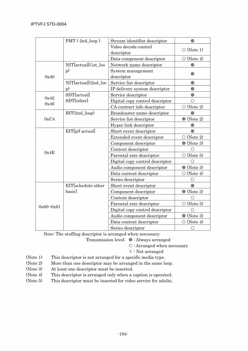
IPTVFJ STD-0004
-194-
PMT ( 2nd_loop ) Stream identifier descriptor Video decode control descriptor (Note 1)
Data component descriptor (Note 4)
0x40
NIT[actual](1st_loop)
Network name descriptor System management descriptor
NIT[actual](2nd_loop)
Service list descriptor IP delivery system descriptor
0x42 0x46
SDT[actual] SDT[other]
Service descriptor Digital copy control descriptor CA contract info descriptor (Note 2)
0xC4 BIT(2nd_loop) Broadcaster name descriptor
Service list descriptor (Note 2) Hyper link descriptor
0x4E
EIT[p/f actual]
Short event descriptor Extended event descriptor (Note 2) Component descriptor (Note 3) Content descriptor Parental rate descriptor (Note 5) Digital copy control descriptor Audio component descriptor (Note 3) Data content descriptor (Note 4) Series descriptor
0x60~0x61
EIT[schedule other basic]
Short event descriptor Component descriptor (Note 3) Content descriptor Parental rate descriptor (Note 5) Digital copy control descriptor Audio component descriptor (Note 3) Data content descriptor (Note 4) Series descriptor
Note: The stuffing descriptor is arranged when necessary. Transmission level: : Always arranged
: Arranged when necessary : Not arranged
(Note 1) This descriptor is not arranged for a specific media type. (Note 2) More than one descriptor may be arranged in the same loop. (Note 3) At least one descriptor must be inserted. (Note 4) This descriptor is arranged only when a caption is operated. (Note 5) This descriptor must be inserted for video service for adults.

IPTVFJ STD-0004
—195—
7.8.3 Tables and Descriptors Used in Individually Operated SI These tables and descriptors are not defined because they are not operated in the IP broadcasting service.
7.9 TS Packetization and Transmission Rules This section describes the specifications to be observed when forming the PSI/SI sections into TS packets and transmitting them.
7.9.1 Detailed Rules for Placement of Sections in TS Packets See ARIB TR-B15 Part 1.
7.9.2 Details of TS Packet Transmission In order to enable the receiver to receive PSI/SI section data on a stable basis, the TS packets shall be transmitted in accordance with the following specifications.
[Transmission operation rules]
(1) When transmitting sections, six or more TS packets shall not be consecutively transmitted by using the same PID. This specification applies when all TS packets are multiplexed on a transport stream, including video and audio data. It is valid irrespective of the band of the transport stream itself.
(2) The TS packets that transmit all the SI sections shall not be sent out at a rate exceeding 1 Mbps for the ordinary TS and 3 Mbps for the SI-exclusive TS. In each case, the number of bits is the total of bits of the SI tables contained in the same transport stream. The SI sections referred to here are the NIT, BIT, SDT, EIT and ST.
(3) The TS packets that transmit PSI sections shall not be sent out at a rate exceeding 320 kbps by using the same PID.
(4) When transmitting sections, TS packets of the same PID shall be sent out at a rate within 4 kB ±100% per 32 ms for the ordinary TS and within 12 kB ±100% per 32 ms for the SI-exclusive TS. The rate of 4 kB (12 kB) per 32 ms restates the rate of 1 Mbps (3 Mbps) in more detail for each PID. This specification presents a reception model for the sections on which these Specifications are based. Namely, this specification requires the receiver to have a 4 kB (12 kB) buffer for reception of data per PID and the ability to process a maximum of 4 kB (12 kB) of section data it receives within 32 ms. The rate of 4 kB (12 kB) ±100% means that a maximum of 8 kB (24 kB) can be transmitted in 32 ms. (Needless to say, considering that the specification described in 2) applies at the same time, it is evident that this condition is a momentary one.) Ordinarily, multiple items of PSI/SI data need to be processed at the same time. However, by taking into account the above reception model, it becomes possible to set optimum conditions for data reception according to the ability of each individual receiver.
IPTVFJ STD-0004
-196-
In IP broadcasts, the above four items are all that apply to the TS packets for transmitting PSI/SI tables. On the premise that the TS packets are sent out in accordance with those four items, the receiver must be so designed that it does not get into any trouble (at least in the TS packet receiving process).
7.9.3 Continuity Counter Ordinarily, the continuity counter is incremented by 1 at a time. However, during a system failure, etc., the continuity counter might be incremented by 2 or more at a time, although it is very rare. It is necessary that the receiver should be capable of normal operation even if such a discontinuity occurs.
7.10 Table (Section) Transmission Operation This section describes details of table (section) transmission operation. In 7.10.1 and 7.10.2, the general specifications on section configuration are described. In 7.10.3 and the subsequent subsections, the table (section) transmission specifications are described in detail with the focus on the concept of the period of transmission.
7.10.1 Division into Sections See ARIB TR-B15.
7.10.2 Placement of Descriptors into Section Concerning the arrangement of descriptors in PSI/SI sections, the following specifications shall be applied.
Basically, the descriptors may be arranged in the descriptor loop in any order. It should be noted, however, that the following rules shall be observed.
[Transmission operation rules]
When there are two or more identical descriptors, they shall be arranged consecutively.
The stream identifier descriptor that is arranged in the PMT shall be placed at the beginning of the descriptor loop.
7.10.3 Definition of Period Group and Retransmission Cycle A period group is an aggregate of information in each of the PSI/SI tables transmitted at the same retransmission cycle. Ordinarily, a period group is set for each PID value and each table_id. However, EIT [schedule] is subject to a special operation. For the concept of period group setting for EIT [schedule], see the description in 7.11.2.
For each period group, a period can be set individually. Multisections are also operated independently at a specific period. (For the relationship between multisection unit and period group, see 7.9.1.)
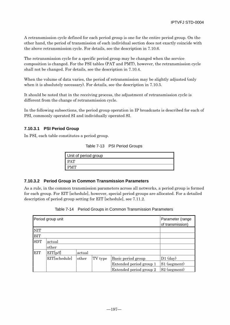
IPTVFJ STD-0004
—197—
A retransmission cycle defined for each period group is one for the entire period group. On the other hand, the period of transmission of each individual section does not exactly coincide with the above retransmission cycle. For details, see the description in 7.10.6.
The retransmission cycle for a specific period group may be changed when the service composition is changed. For the PSI tables (PAT and PMT), however, the retransmission cycle shall not be changed. For details, see the description in 7.10.4.
When the volume of data varies, the period of retransmission may be slightly adjusted (only when it is absolutely necessary). For details, see the description in 7.10.5.
It should be noted that in the receiving process, the adjustment of retransmission cycle is different from the change of retransmission cycle.
In the following subsections, the period group operation in IP broadcasts is described for each of PSI, commonly operated SI and individually operated SI.
7.10.3.1 PSI Period Group In PSI, each table constitutes a period group.
Table 7-13 PSI Period Groups
Unit of period group PAT PMT
7.10.3.2 Period Group in Common Transmission Parameters As a rule, in the common transmission parameters across all networks, a period group is formed for each group. For EIT [schedule], however, special period groups are allocated. For a detailed description of period group setting for EIT [schedule], see 7.11.2.
Table 7-14 Period Groups in Common Transmission Parameters
Period group unit Parameter (range of transmission)
NIT BIT SDT actual
other EIT EIT[p/f] actual
EIT[schedule] other TV type Basic period group D1 (day) Extended period group 1 S1 (segment) Extended period group 2 S2 (segment)
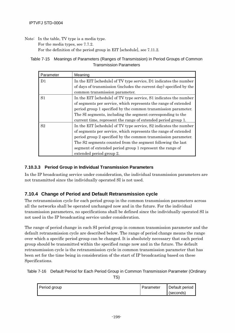
IPTVFJ STD-0004
-198-
Note: In the table, TV type is a media type. For the media types, see 7.7.2. For the definition of the period group in EIT [schedule], see 7.11.2.
Table 7-15 Meanings of Parameters (Ranges of Transmission) in Period Groups of Common Transmission Parameters
Parameter Meaning D1 In the EIT [schedule] of TV type service, D1 indicates the number
of days of transmission (includes the current day) specified by the common transmission parameter.
S1 In the EIT [schedule] of TV type service, S1 indicates the number of segments per service, which represents the range of extended period group 1 specified by the common transmission parameter. The SI segments, including the segment corresponding to the current time, represent the range of extended period group 1.
S2 In the EIT [schedule] of TV type service, S2 indicates the number of segments per service, which represents the range of extended period group 2 specified by the common transmission parameter. The S2 segments counted from the segment following the last segment of extended period group 1 represent the range of extended period group 2.
7.10.3.3 Period Group in Individual Transmission Parameters In the IP broadcasting service under consideration, the individual transmission parameters are not transmitted since the individually operated SI is not used.
7.10.4 Change of Period and Default Retransmission cycle The retransmission cycle for each period group in the common transmission parameters across all the networks shall be operated unchanged now and in the future. For the individual transmission parameters, no specifications shall be defined since the individually operated SI is not used in the IP broadcasting service under consideration.
The range of period change in each SI period group in common transmission parameter and the default retransmission cycle are described below. The range of period change means the range over which a specific period group can be changed. It is absolutely necessary that each period group should be transmitted within the specified range now and in the future. The default retransmission cycle is the retransmission cycle in common transmission parameter that has been set for the time being in consideration of the start of IP broadcasting based on these Specifications.
Table 7-16 Default Period for Each Period Group in Common Transmission Parameter (Ordinary TS)
Period group Parameter Default period (seconds)

IPTVFJ STD-0004
—199—
NIT 1 BIT 1 SDT[actual] 2 EIT[p/f actual] 1
Table 7-17 Default Period for Each Period Group in Common Transmission Parameter (SI-Exclusive TS)
Period group Parameter Default period (seconds)
NIT 1 BIT 1 SDT[other] 5 EIT[schedule] other TV type Basic period group D1 180
Extended period group 1
S1 5
Extended period group 2
S2 20
Table 7-18 Parameters Showing Range of Period Group in Common Transmission Parameter
Parameter Default
D1 8 days S1 3 segments S2 13 segments
Note: When the media type is TV type, the default of 8-day description for D1 and the default of 3 segments for S1 shall be operated fixed. The default of 3 segments is intended to enable cutting the information acquisition time, at least for 9 hours of program information, in consideration of the scope of display of the program table, etc.
For PSI, the period shall not be changed.
The retransmission cycle of each PSI table is shown below.
Table 7-19 PSI Retransmission cycle
Period group Retransmission cycle (seconds)
PAT 0.1 PMT 0.1
IPTVFJ STD-0004
-200-
7.10.5 Period Adjustment Ordinarily, each of the PSI/SI tables is transmitted at a retransmission cycle defined for each period group. However, there are cases in which the prescribed retransmission cycle is slightly shifted in order to deal with a difference in data volume, etc. from one time belt to another. (When preparing SI data, it is common practice to minutely define the volume of data so as to prevent the variation of data volume from one time belt to another. However, the variation of data volume cannot always be avoided because of a difference in data volume between EIT [p/f] events, a change made during event programming, etc.
The adjustable range of retransmission cycle in such cases is described below. In light of the following retransmission operation rules, the receiver should be so designed that it does not get into any trouble in the receiving process.
[Transmission operation rules]
For each of the tables defined in PSI/SI, the retransmission cycle set for each period group ±10% shall be the period adjustable range. In the case of EIT [p/f actual], for example, the prescribed period of 1 second may be changed within the range 0.9 to 1.1 seconds if the change is required due to the volume of transmission data, etc.
The adjustment of a period must always be made for each period group. For details, see the description in 7.10.7.
7.10.6 Transmission Interval of Each Section The retransmission cycle set for each period group does not indicate the interval of transmission of each of the sections in the period group. It is conceivable that the interval of transmission of a specific section in a period group varies widely due to a transmission jitter within the period group (see the description in 7.10.7 for details of SI transmission within a period group) or the behavior of the section when the data is updated (see the description in 7.10.8). It should be noted, however, that since the interval of section transmission is considered important because it is a major factor in the setting of a timeout for the receiver, it shall be operated in accordance with the following specifications.
[Transmission operation rules]
The maximum interval of transmission of each section shall be two times the retransmission cycle set for the period group to which the section belongs. Since this value is considered sufficient for said section to be transmitted without fail, it should be able to be used in the setting of a receiver timeout, etc. For example, any section that belongs to a period group having a retransmission cycle of 10 seconds can be positively transmitted in 22 seconds (two times 10 seconds plus the maximum adjustment period of 10%).
7.10.7 Details of SI Transmission within Period Group Within the range of the retransmission cycle set for each period group, SI shall be transmitted in accordance with the following specifications and guidelines.
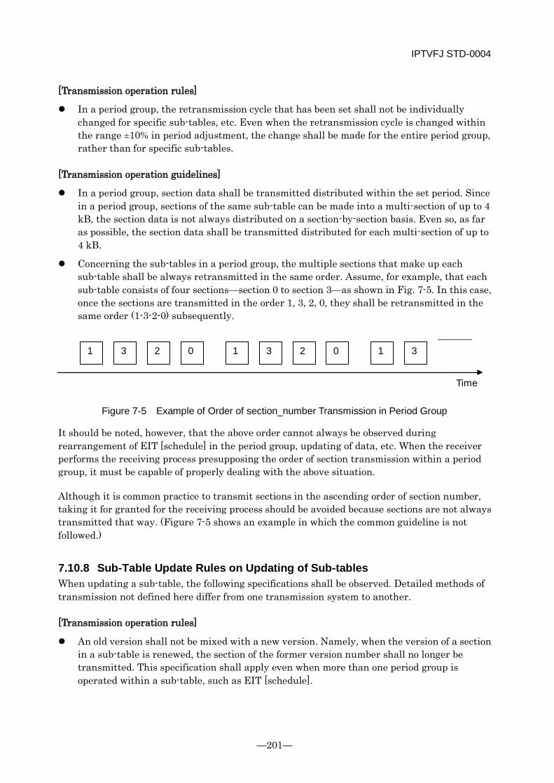
IPTVFJ STD-0004
—201—
[Transmission operation rules]
In a period group, the retransmission cycle that has been set shall not be individually changed for specific sub-tables, etc. Even when the retransmission cycle is changed within the range ±10% in period adjustment, the change shall be made for the entire period group, rather than for specific sub-tables.
[Transmission operation guidelines]
In a period group, section data shall be transmitted distributed within the set period. Since in a period group, sections of the same sub-table can be made into a multi-section of up to 4 kB, the section data is not always distributed on a section-by-section basis. Even so, as far as possible, the section data shall be transmitted distributed for each multi-section of up to 4 kB.
Concerning the sub-tables in a period group, the multiple sections that make up each sub-table shall be always retransmitted in the same order. Assume, for example, that each sub-table consists of four sections—section 0 to section 3—as shown in Fig. 7-5. In this case, once the sections are transmitted in the order 1, 3, 2, 0, they shall be retransmitted in the same order (1-3-2-0) subsequently.
Figure 7-5 Example of Order of section_number Transmission in Period Group
It should be noted, however, that the above order cannot always be observed during rearrangement of EIT [schedule] in the period group, updating of data, etc. When the receiver performs the receiving process presupposing the order of section transmission within a period group, it must be capable of properly dealing with the above situation.
Although it is common practice to transmit sections in the ascending order of section number, taking it for granted for the receiving process should be avoided because sections are not always transmitted that way. (Figure 7-5 shows an example in which the common guideline is not followed.)
7.10.8 Sub-Table Update Rules on Updating of Sub-tables When updating a sub-table, the following specifications shall be observed. Detailed methods of transmission not defined here differ from one transmission system to another.
[Transmission operation rules]
An old version shall not be mixed with a new version. Namely, when the version of a section in a sub-table is renewed, the section of the former version number shall no longer be transmitted. This specification shall apply even when more than one period group is operated within a sub-table, such as EIT [schedule].
1 2 3 0 1 2 3 0 1 3
Time
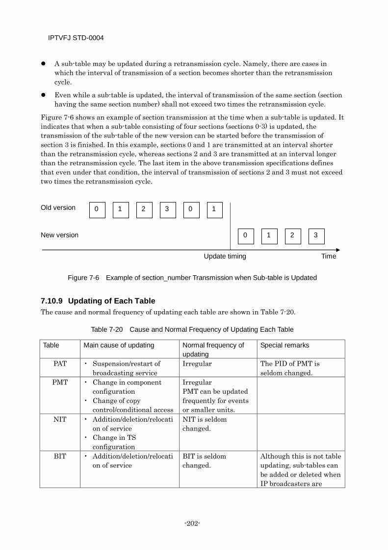
IPTVFJ STD-0004
-202-
A sub-table may be updated during a retransmission cycle. Namely, there are cases in which the interval of transmission of a section becomes shorter than the retransmission cycle.
Even while a sub-table is updated, the interval of transmission of the same section (section having the same section number) shall not exceed two times the retransmission cycle.
Figure 7-6 shows an example of section transmission at the time when a sub-table is updated. It indicates that when a sub-table consisting of four sections (sections 0-3) is updated, the transmission of the sub-table of the new version can be started before the transmission of section 3 is finished. In this example, sections 0 and 1 are transmitted at an interval shorter than the retransmission cycle, whereas sections 2 and 3 are transmitted at an interval longer than the retransmission cycle. The last item in the above transmission specifications defines that even under that condition, the interval of transmission of sections 2 and 3 must not exceed two times the retransmission cycle.
Old version New version
Figure 7-6 Example of section_number Transmission when Sub-table is Updated
7.10.9 Updating of Each Table The cause and normal frequency of updating each table are shown in Table 7-20.
Table 7-20 Cause and Normal Frequency of Updating Each Table
Table Main cause of updating Normal frequency of updating
Special remarks
PAT • Suspension/restart of broadcasting service
Irregular The PID of PMT is seldom changed.
PMT • Change in component configuration
• Change of copy control/conditional access
Irregular PMT can be updated frequently for events or smaller units.
NIT • Addition/deletion/relocation of service
• Change in TS configuration
NIT is seldom changed.
BIT • Addition/deletion/relocation of service
BIT is seldom changed.
Although this is not table updating, sub-tables can be added or deleted when IP broadcasters are
0 1 2 3 0 1
0 1 2 3
Time Update timing
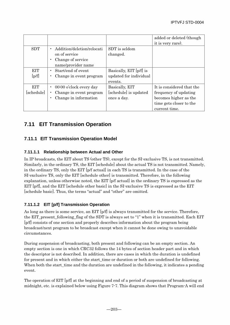
IPTVFJ STD-0004
—203—
added or deleted (though it is very rare).
SDT • Addition/deletion/relocation of service
• Change of service name/provider name
SDT is seldom changed.
EIT [p/f]
• Start/end of event • Change in event program
Basically, EIT [p/f] is updated for individual events.
EIT [schedule]
• 00:00 o’clock every day • Change in event program • Change in information
Basically, EIT [schedule] is updated once a day.
It is considered that the frequency of updating becomes higher as the time gets closer to the current time.
7.11 EIT Transmission Operation
7.11.1 EIT Transmission Operation Model
7.11.1.1 Relationship between Actual and Other In IP broadcasts, the EIT about TS (other TS), except for the SI-exclusive TS, is not transmitted. Similarly, in the ordinary TS, the EIT [schedule] about the actual TS is not transmitted. Namely, in the ordinary TS, only the EIT [p/f actual] in each TS is transmitted. In the case of the SI-exclusive TS, only the EIT [schedule other] is transmitted. Therefore, in the following explanation, unless otherwise noted, the EIT [p/f actual] in the ordinary TS is expressed as the EIT [p/f], and the EIT [schedule other basic] in the SI-exclusive TS is expressed as the EIT [schedule basic]. Thus, the terms “actual” and “other” are omitted.
7.11.1.2 EIT [p/f] Transmission Operation As long as there is some service, an EIT [p/f] is always transmitted for the service. Therefore, the EIT_present_following_flag of the SDT is always set to “1” when it is transmitted. Each EIT [p/f] consists of one section and properly describes information about the program being broadcast/next program to be broadcast except when it cannot be done owing to unavoidable circumstances.
During suspension of broadcasting, both present and following can be an empty section. An empty section is one in which CRC32 follows the 14 bytes of section header part and in which the descriptor is not described. In addition, there are cases in which the duration is undefined for present and in which either the start_time or duration or both are undefined for following. When both the start_time and the duration are undefined in the following, it indicates a pending event.
The operation of EIT [p/f] at the beginning and end of a period of suspension of broadcasting at midnight, etc. is explained below using Figure 7-7. This diagram shows that Program-A will end

IPTVFJ STD-0004
-204-
at 1:00 a.m. and the next Program-B is scheduled to start at 2:00 a.m. The basic operation is that the information about Program-B is described in EIT [f] and transmitted while Program-A is being broadcast (Pattern 1). Depending on the transmitting equipment, however, EIT [f] becomes an empty section (Pattern 2). In Pattern 2, the EIT [f] during the period of suspension is also an empty section. In this case, the information about Program-B must be described in the EIT [f] and transmitted not later than 30 seconds before Program-B starts.
It should be noted that the above period of suspension does not necessarily imply the suspension of video/audio components.
Figure 7-7 Transmission Operation of EIT [p/f] at Beginning and End of Suspension of Program Broadcast
The EIT [p/f actual] is program information about the service defined in the actual TS. Concerning an event broadcast by the actual TS over the actual network, it sets and generates the descriptors of commonly operated SI (see Table 7-12).
When transmitted, it forms a single period group regardless of the media type. The retransmission cycle is unified among all TS.
In the EIT [p/f], the running status shall always be “undefined” (0x0).
7.11.1.3 EIT [schedule basic] Transmission Operation
7.11.1.3.1 EIT [schedule basic] Transmission Operation Common to EIT for Common Operation and EIT for Individual Operation
Like the commonly operated SI and the individually operated SI described in 7.8, there are two types of EIT [schedule basic]—the EIT for common operation (EIT operated in common to all networks) and the EIT for individual operation (EIT operated differently from one network to another). As a rule, the EIT for common operation shall be operated.
The EIT [schedule basic] shall be transmitted in a period group which differs according to the media type. It should be noted, however, that in IP broadcasts, only the TV type shall be operated.
For an EIT [schedule basic], a table of a maximum of 8 sections shall be used every three hours (segment).
Program-A event_id=0x1023 Suspension period Program-B
event_id=0x1033
AM 1:00 AM 2:00
Program arrangement
EIT[p] = Program-A/EIT[f] = Program-B EIT[p] = Empty section/EIT[f] = Program-B EIT[p] = Program-B
EIT[p] = Program-A/EIT[f] = Empty section EIT[p] = Empty section/EIT[f] = Empty section EIT[p] = Program-B
EIT[p] = Empty section/EIT[f] = Program-B
AM 1:59:30 Pattern 1
Pattern 2
IPTVFJ STD-0004
—205—
The first EIT [schedule basic] that is transmitted (for example, the schedule for the eighth day from the start of transmission) shall be defined as the original one. For the original EIT [schedule basic], the copy control descriptor, parental rate descriptor and CA contract info descriptor that influence the reservation operation, etc. must not be changed. However, there are cases in which the short event descriptor and extended event descriptor are changed under unavoidable circumstances, such as when it is necessary to correct the name of a person.
When either start_time or duration or both are undefined in a program, the EIT [schedule basic] shall not be transmitted. The running status shall always be “undefined” (0x0).
7.11.1.3.2 EIT [schedule basic] Transmission Operation in Scope of EIT for Common Operation
In the scope of EIT for common operation, when the media type is TV type, the EIT [schedule basic] must be transmitted as one for D1 days (default value: 8 days) from the current day. Once it is decided to transmit any service, it shall be transmitted on a stable basis. On the current day, however, the EIT [schedule basic] shall be transmitted only in and after the segments including the current time. The transmission of the EIT [schedule basic] that has passed said time with the lapse of time shall be stopped in segments.
The EIT for common operation must not be operated using a value different from the default value.
The retransmission cycle defined for each period group shall be uniformly operated in all the networks. The EIT [schedule] period group is explained in detail in 7.11.2.
7.11.1.3.3 EIT [schedule basic] Transmission Operation in Scope of EIT for Individual Operation
The EIT for individual operation shall not be defined here since it is not operated in the IP broadcasting service under consideration.
7.11.1.4 Transmission Operation of EIT [schedule extended] The EIT [schedule extended] shall not be defined here since it is not operated in the IP broadcasting service under consideration.
7.11.2 Setting EIT [schedule] Period Group The EIT [schedule] integrates multiple tables to constitute a single unit of program information. In addition, it contains much larger amounts of data than other types of SI information. Therefore, the method of setting a period group for EIT [schedule] is different from the ordinary one in which a period group is set for each PID and each table_id. The concept of period group setting for EIT [schedule] is explained in detail below.
The transmission parameters of EIT[schedule] for common operation are common to all networks and operated fixed in the future.

IPTVFJ STD-0004
-206-
The EIT[schedule] period groups are divided into the basic period group and the extended period group.
In IP broadcasts, the EIT[schedule] is transmitted at a very long retransmission cycle on the premise that it is stored in the receiver before it is used. The period group that sets such a long retransmission cycle is called the basic period group. On the other hand, there are cases in which a period group having a short retransmission cycle is set to permit the receiver to perform certain operations during startup, etc. even when EIT[schedule] is not stored. This period group is called the extended period group.
The basic period group and extended period group are set for each of the table types of EIT[schedule]. Although the number of period groups is invariable, the number of transmission parameters for each period group is variable.
The basic period group and extended period group for each table type of EIT[schedule] (when viewed as one service) have the following relationships.
The basic period group has a longer retransmission cycle than all the extended period groups.
The extended period groups are continuous on the EIT[schedule] time axis, and the earlier the time, the shorter is the retransmission cycle of the period group.
The extended period group that has the shortest retransmission cycle always contains the segment of the current instant.
The EIT[schedule] shall be operated for each media type (see 7.7.2). If the EIT[schedule] is operated for different media types, the number of days of event information transmitted as EIT[schedule] differs and different retransmission cycles are set. It should be noted, however, that only the TV type is operated in IP broadcasts.
Whether or not to transmit an EIT[schedule] for specific service_type is shown in Table 7-21.
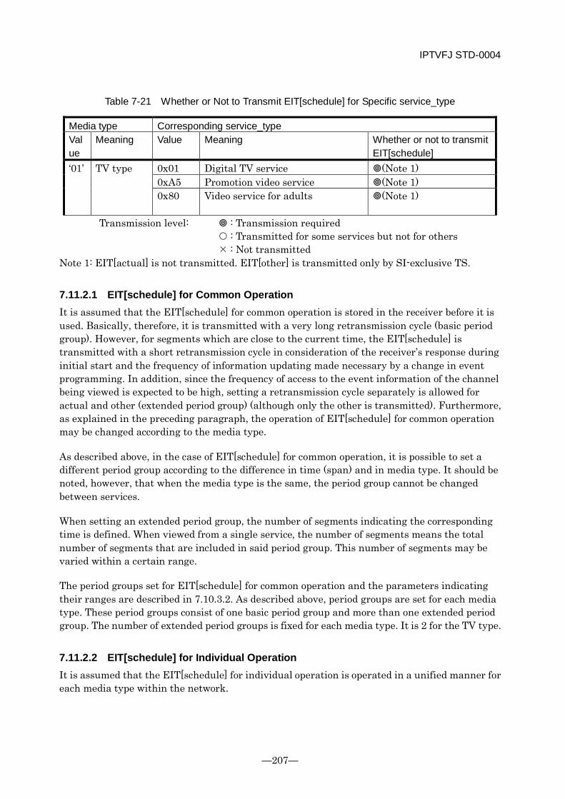
IPTVFJ STD-0004
—207—
Table 7-21 Whether or Not to Transmit EIT[schedule] for Specific service_type
Media type Corresponding service_type Value
Meaning Value Meaning Whether or not to transmit EIT[schedule]
‘01’ TV type 0x01 Digital TV service (Note 1) 0xA5 Promotion video service (Note 1) 0x80
Video service for adults (Note 1)
Transmission level: : Transmission required : Transmitted for some services but not for others : Not transmitted Note 1: EIT[actual] is not transmitted. EIT[other] is transmitted only by SI-exclusive TS.
7.11.2.1 EIT[schedule] for Common Operation It is assumed that the EIT[schedule] for common operation is stored in the receiver before it is used. Basically, therefore, it is transmitted with a very long retransmission cycle (basic period group). However, for segments which are close to the current time, the EIT[schedule] is transmitted with a short retransmission cycle in consideration of the receiver’s response during initial start and the frequency of information updating made necessary by a change in event programming. In addition, since the frequency of access to the event information of the channel being viewed is expected to be high, setting a retransmission cycle separately is allowed for actual and other (extended period group) (although only the other is transmitted). Furthermore, as explained in the preceding paragraph, the operation of EIT[schedule] for common operation may be changed according to the media type.
As described above, in the case of EIT[schedule] for common operation, it is possible to set a different period group according to the difference in time (span) and in media type. It should be noted, however, that when the media type is the same, the period group cannot be changed between services.
When setting an extended period group, the number of segments indicating the corresponding time is defined. When viewed from a single service, the number of segments means the total number of segments that are included in said period group. This number of segments may be varied within a certain range.
The period groups set for EIT[schedule] for common operation and the parameters indicating their ranges are described in 7.10.3.2. As described above, period groups are set for each media type. These period groups consist of one basic period group and more than one extended period group. The number of extended period groups is fixed for each media type. It is 2 for the TV type.
7.11.2.2 EIT[schedule] for Individual Operation It is assumed that the EIT[schedule] for individual operation is operated in a unified manner for each media type within the network.
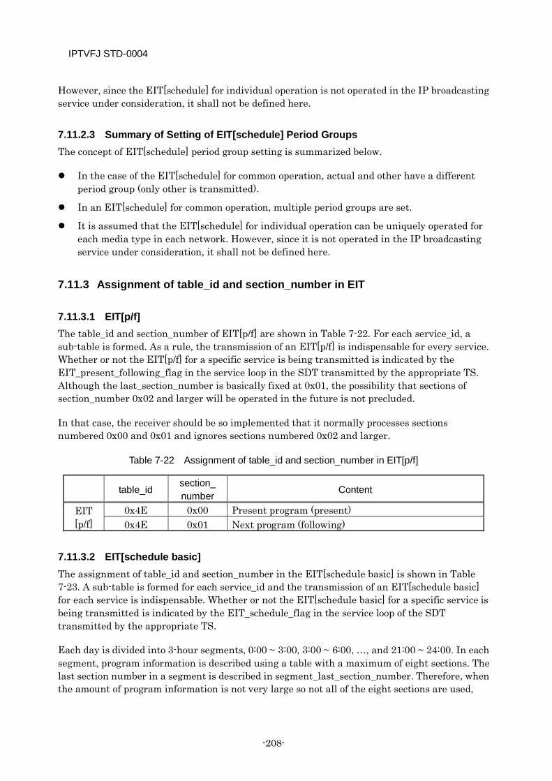
IPTVFJ STD-0004
-208-
However, since the EIT[schedule] for individual operation is not operated in the IP broadcasting service under consideration, it shall not be defined here.
7.11.2.3 Summary of Setting of EIT[schedule] Period Groups The concept of EIT[schedule] period group setting is summarized below.
In the case of the EIT[schedule] for common operation, actual and other have a different period group (only other is transmitted).
In an EIT[schedule] for common operation, multiple period groups are set.
It is assumed that the EIT[schedule] for individual operation can be uniquely operated for each media type in each network. However, since it is not operated in the IP broadcasting service under consideration, it shall not be defined here.
7.11.3 Assignment of table_id and section_number in EIT
7.11.3.1 EIT[p/f] The table_id and section_number of EIT[p/f] are shown in Table 7-22. For each service_id, a sub-table is formed. As a rule, the transmission of an EIT[p/f] is indispensable for every service. Whether or not the EIT[p/f] for a specific service is being transmitted is indicated by the EIT_present_following_flag in the service loop in the SDT transmitted by the appropriate TS. Although the last_section_number is basically fixed at 0x01, the possibility that sections of section_number 0x02 and larger will be operated in the future is not precluded.
In that case, the receiver should be so implemented that it normally processes sections numbered 0x00 and 0x01 and ignores sections numbered 0x02 and larger.
Table 7-22 Assignment of table_id and section_number in EIT[p/f]
table_id section_ number Content
EIT [p/f]
0x4E 0x00 Present program (present) 0x4E 0x01 Next program (following)
7.11.3.2 EIT[schedule basic] The assignment of table_id and section_number in the EIT[schedule basic] is shown in Table 7-23. A sub-table is formed for each service_id and the transmission of an EIT[schedule basic] for each service is indispensable. Whether or not the EIT[schedule basic] for a specific service is being transmitted is indicated by the EIT_schedule_flag in the service loop of the SDT transmitted by the appropriate TS.
Each day is divided into 3-hour segments, 0:00 ~ 3:00, 3:00 ~ 6:00, …, and 21:00 ~ 24:00. In each segment, program information is described using a table with a maximum of eight sections. The last section number in a segment is described in segment_last_section_number. Therefore, when the amount of program information is not very large so not all of the eight sections are used,
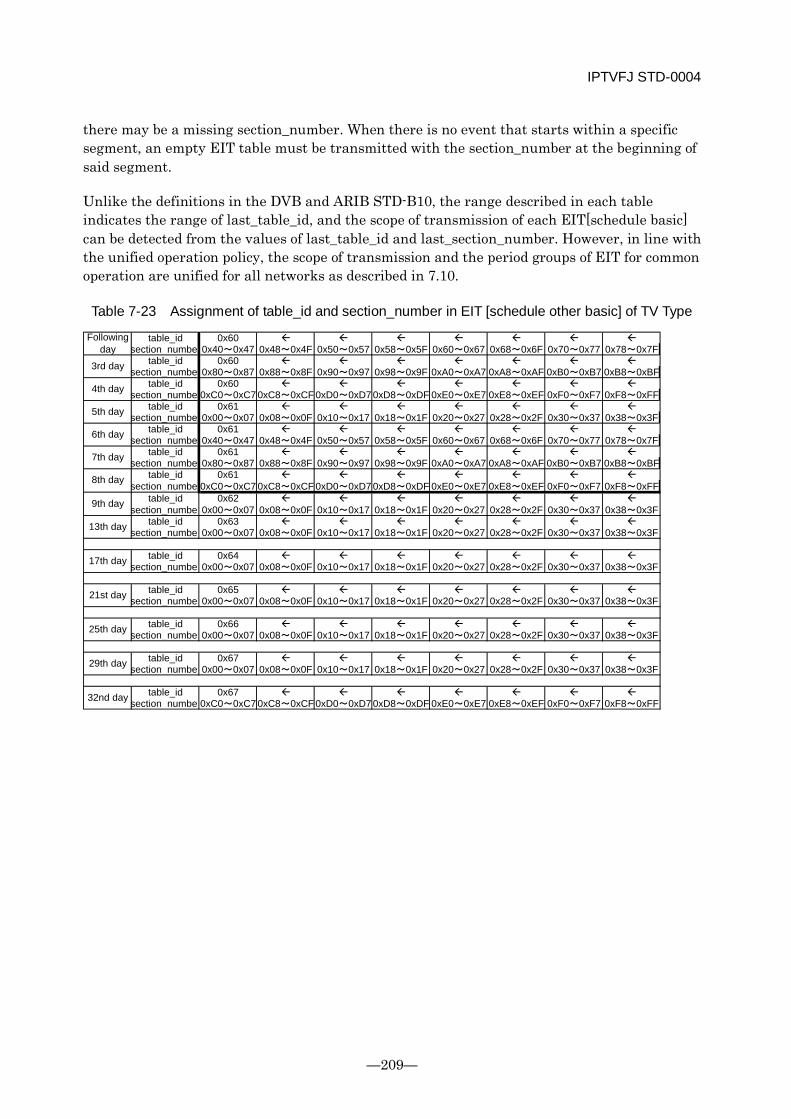
IPTVFJ STD-0004
—209—
there may be a missing section_number. When there is no event that starts within a specific segment, an empty EIT table must be transmitted with the section_number at the beginning of said segment.
Unlike the definitions in the DVB and ARIB STD-B10, the range described in each table indicates the range of last_table_id, and the scope of transmission of each EIT[schedule basic] can be detected from the values of last_table_id and last_section_number. However, in line with the unified operation policy, the scope of transmission and the period groups of EIT for common operation are unified for all networks as described in 7.10.
Table 7-23 Assignment of table_id and section_number in EIT [schedule other basic] of TV Type
table_id 0x60 section_number0x40~0x47 0x48~0x4F 0x50~0x57 0x58~0x5F 0x60~0x67 0x68~0x6F 0x70~0x77 0x78~0x7F
table_id 0x60 section_number0x80~0x87 0x88~0x8F 0x90~0x97 0x98~0x9F 0xA0~0xA7 0xA8~0xAF 0xB0~0xB7 0xB8~0xBF
table_id 0x60 section_number0xC0~0xC7 0xC8~0xCF 0xD0~0xD7 0xD8~0xDF 0xE0~0xE7 0xE8~0xEF 0xF0~0xF7 0xF8~0xFF
table_id 0x61 section_number0x00~0x07 0x08~0x0F 0x10~0x17 0x18~0x1F 0x20~0x27 0x28~0x2F 0x30~0x37 0x38~0x3F
table_id 0x61 section_number0x40~0x47 0x48~0x4F 0x50~0x57 0x58~0x5F 0x60~0x67 0x68~0x6F 0x70~0x77 0x78~0x7F
table_id 0x61 section_number0x80~0x87 0x88~0x8F 0x90~0x97 0x98~0x9F 0xA0~0xA7 0xA8~0xAF 0xB0~0xB7 0xB8~0xBF
table_id 0x61 section_number0xC0~0xC7 0xC8~0xCF 0xD0~0xD7 0xD8~0xDF 0xE0~0xE7 0xE8~0xEF 0xF0~0xF7 0xF8~0xFF
table_id 0x62 section_number0x00~0x07 0x08~0x0F 0x10~0x17 0x18~0x1F 0x20~0x27 0x28~0x2F 0x30~0x37 0x38~0x3F
table_id 0x63 section_number0x00~0x07 0x08~0x0F 0x10~0x17 0x18~0x1F 0x20~0x27 0x28~0x2F 0x30~0x37 0x38~0x3F
table_id 0x64 section_number0x00~0x07 0x08~0x0F 0x10~0x17 0x18~0x1F 0x20~0x27 0x28~0x2F 0x30~0x37 0x38~0x3F
table_id 0x65 section_number0x00~0x07 0x08~0x0F 0x10~0x17 0x18~0x1F 0x20~0x27 0x28~0x2F 0x30~0x37 0x38~0x3F
table_id 0x66 section_number0x00~0x07 0x08~0x0F 0x10~0x17 0x18~0x1F 0x20~0x27 0x28~0x2F 0x30~0x37 0x38~0x3F
table_id 0x67 section_number0x00~0x07 0x08~0x0F 0x10~0x17 0x18~0x1F 0x20~0x27 0x28~0x2F 0x30~0x37 0x38~0x3F
table_id 0x67 section_number0xC0~0xC7 0xC8~0xCF 0xD0~0xD7 0xD8~0xDF 0xE0~0xE7 0xE8~0xEF 0xF0~0xF7 0xF8~0xFF32nd day
21st day
25th day
29th day
8th day
9th day
13th day
17th day
4th day
5th day
6th day
7th day
Followingday
3rd day
IPTVFJ STD-0004
-210-
7.11.3.3 EIT[schedule extended] In IP broadcasts, as in BS/wide-band CS broadcasts and terrestrial broadcasts, it is presupposed that the EIT[schedule extended] will be operated with the scope of transmission and the description of descriptors fixed. However, since the EIT[schedule extended] is not operated in the IP broadcasting service under consideration, it is not defined here.
7.11.4 EIT[schedule] Transmission Operation with Lapse of Time The transmission of the sub-tables in each segment is stopped when the information contained in them becomes obsolete with the lapse of time. For example, the transmission of the segment containing information about the programs that are scheduled to start between 15:00 and 18:00 is stopped immediately at 18:00. Therefore, in the case of a program which extends over two segments, there is a certain time in which the EIT[schedule] is not transmitted for the program being broadcast. (In this case, the program is described only in the EIT[p/f].)
At 0:00 every day, the table_number and section_number are updated and the last day of the schedule (8 segments) in the scope defined for each media type is added. Thus, since the transmission of sub-tables is stopped by segment and started by day, the number of segments transmitted decreases by 1 every three hours to become 0 at the end of the day, when it returns to 8.
In a hierarchical transmission period (the transmission period changes according to the time span from the present), the information transmitted is shifted by segment. Namely, the transmission period defined for program information for 48 hours from the present, for example, means, at any point of time, the “period in which program information for 16 segments, including the segment to which the present belongs, is transmitted”.
Example: Assume that the present time is 19:30 on the 15th day. Then, the information transmitted in a “period of 48 hours from the present” is the information about the programs that start between 18:00 on the 15th day and 18:00 on the 17th day (information about the program that starts at 18:00 on the 17th day is not included).
7.11.5 Rules on Update Operation at End of Day Because of its structure, the EIT[schedule] must be updated at 0:00 every day. In the updating process, the following specifications shall apply.
(1) The updating process shall not take place before 0:00.
(2) A transition period of 60 seconds shall be set exactly at 0:00.
(3) After the transition period has passed, the EIT[schedule] of the old version (for the previous day) shall not be transmitted.
During the transition period, the transmission of the old version (the previous day’s table) is stopped and the transmission of the new version (the current day’s table) is started. Details of
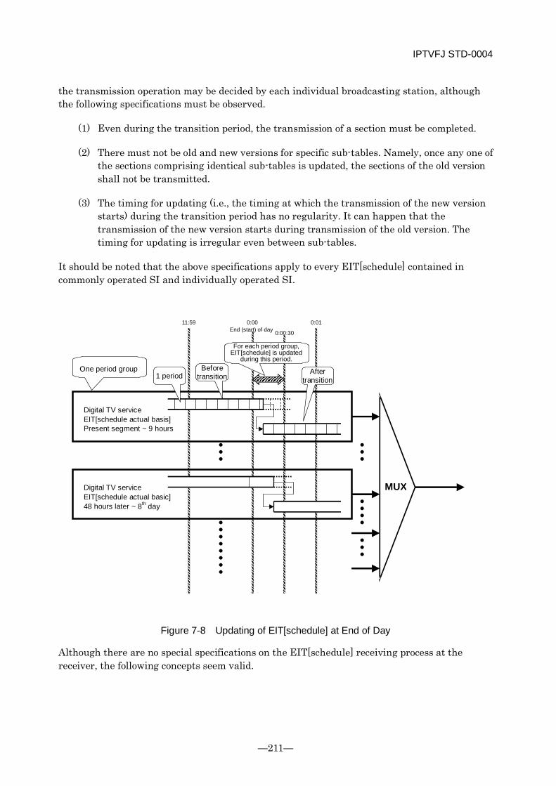
IPTVFJ STD-0004
—211—
the transmission operation may be decided by each individual broadcasting station, although the following specifications must be observed.
(1) Even during the transition period, the transmission of a section must be completed.
(2) There must not be old and new versions for specific sub-tables. Namely, once any one of the sections comprising identical sub-tables is updated, the sections of the old version shall not be transmitted.
(3) The timing for updating (i.e., the timing at which the transmission of the new version starts) during the transition period has no regularity. It can happen that the transmission of the new version starts during transmission of the old version. The timing for updating is irregular even between sub-tables.
It should be noted that the above specifications apply to every EIT[schedule] contained in commonly operated SI and individually operated SI.
Figure 7-8 Updating of EIT[schedule] at End of Day
Although there are no special specifications on the EIT[schedule] receiving process at the receiver, the following concepts seem valid.
11:59 0:00 End (start) of day
0:01
Digital TV service EIT[schedule actual basis] Present segment ~ 9 hours
MUX
0:00:30
One period group 1 period
Before transition
After transition
For each period group, EIT[schedule] is updated
during this period.
Digital TV service EIT[schedule actual basic] 48 hours later ~ 8th day
IPTVFJ STD-0004
-212-
(1) Since the current version is not replaced with a new version before 0:00, the receiver can perform the processing as usual until then. In this case, it is important to confirm that the processing performed does not extend beyond 0:00.
(2) Once the transition period has passed, the processing becomes stable. Therefore, the batch-receiving process, etc. should be performed after the transition period. However, since the content of the program information itself is not always changed, storing the program information of the old version is not always useless.
(3) When the transition period following 0:00 passes, the segment position always changes. It should not be expected that a segment before the change is transmitted during the transition period. It is necessary to pay special attention when acquiring a segment which extends beyond 0:00.
(4) When acquiring a specified segment to monitor updating of the scope of display of program table, for example, if the value of version_number at the new segment position is previously known, it is advisable to change the segment position exactly at 0:00 and obtain the program information using the value of the new version_number. (When it is necessary to set a timeout for the process, the transition period should be added to the timeout.) Even when the value of version_number is not previously known, it is generally possible to judge whether the version is old or new from the relationship between the acquired segment and the program starting time. It should be noted, however, that the above judgment cannot be made when there are no events (the section is empty). In this case, it is necessary to wait till the transition period ends.
7.12 Use of component_tag For all the ES defined in the PMT, setting a value of component_tag (arrangement of a stream identifier descriptor) is indispensable. In this subsection, the operation of component_tag and PID for ES is described.
7.12.1 Concept of component_tag and PID In both channel selection and reservation, the user selects the appropriate ES using SI. Therefore, the component_tag value that relates the user interface to a specific ES has an important meaning. During channel selection, the receiver selects an ES on the basis of the component_tag, finds its PID, separates the ES from the TS and decodes it. Concerning the ES that is being selected (displayed) too, the receiver continues decoding ES having the same value of component_tag. Namely, when ES of component_tag=”0x11” is displayed, for example, the receiver continues decoding ES of “0x11”, regardless of whether it is in an event or between events, unless the viewer performs some operation. When the component_tag that the receiver has selected and received disappears, the receiver selects a new component_tag. Therefore, the processing performed by the receiver becomes the same as in channel selection.
The principle that ES having the same component_tag value continues to be decoded applies even when the value of PID having said component_tag value is changed. However, when the ES_PID information defined in the PMT is changed, the receiver performs PID filtering control.
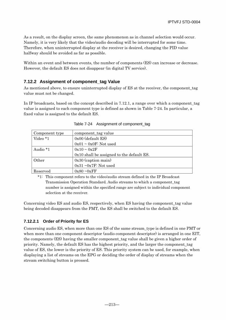
IPTVFJ STD-0004
—213—
As a result, on the display screen, the same phenomenon as in channel selection would occur. Namely, it is very likely that the video/audio decoding will be interrupted for some time. Therefore, when uninterrupted display at the receiver is desired, changing the PID value halfway should be avoided as far as possible.
Within an event and between events, the number of components (ES) can increase or decrease. However, the default ES does not disappear (in digital TV service).
7.12.2 Assignment of component_tag Value As mentioned above, to ensure uninterrupted display of ES at the receiver, the component_tag value must not be changed.
In IP broadcasts, based on the concept described in 7.12.1, a range over which a component_tag value is assigned to each component type is defined as shown in Table 7-24. In particular, a fixed value is assigned to the default ES.
Table 7-24 Assignment of component_tag
Component type component_tag value Video *1 0x00 (default ES)
0x01 ~ 0x0F: Not used Audio *1 0x10 ~ 0x2F
0x10 shall be assigned to the default ES. Other 0x30 (caption main)
0x31 ~0x7F: Not used Reserved 0x80 ~0xFF
*1: This component refers to the video/audio stream defined in the IP Broadcast Transmission Operation Standard. Audio streams to which a component_tag number is assigned within the specified range are subject to individual component selection at the receiver.
Concerning video ES and audio ES, respectively, when ES having the component_tag value being decoded disappears from the PMT, the ES shall be switched to the default ES.
7.12.2.1 Order of Priority for ES Concerning audio ES, when more than one ES of the same stream_type is defined in one PMT or when more than one component descriptor (audio component descriptor) is arranged in one EIT, the components (ES) having the smaller component_tag value shall be given a higher order of priority. Namely, the default ES has the highest priority, and the larger the component_tag value of ES, the lower is the priority of ES. This priority system can be used, for example, when displaying a list of streams on the EPG or deciding the order of display of streams when the stream switching button is pressed.
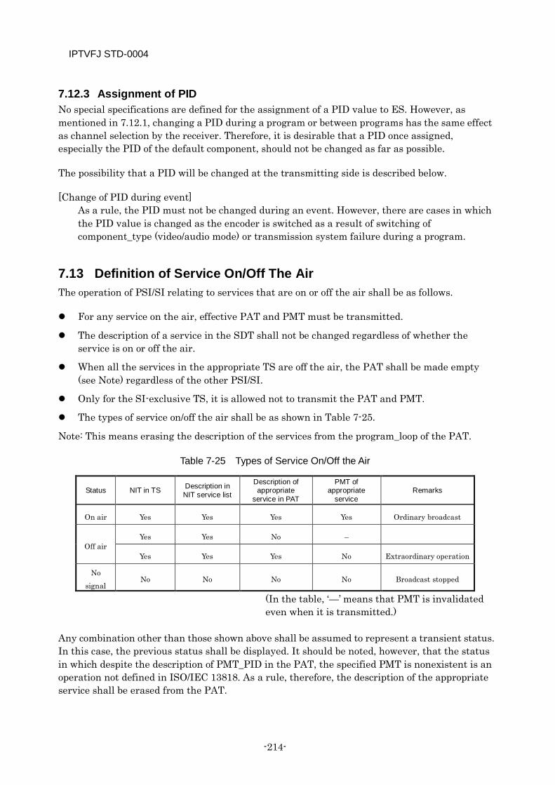
IPTVFJ STD-0004
-214-
7.12.3 Assignment of PID No special specifications are defined for the assignment of a PID value to ES. However, as mentioned in 7.12.1, changing a PID during a program or between programs has the same effect as channel selection by the receiver. Therefore, it is desirable that a PID once assigned, especially the PID of the default component, should not be changed as far as possible.
The possibility that a PID will be changed at the transmitting side is described below.
[Change of PID during event] As a rule, the PID must not be changed during an event. However, there are cases in which the PID value is changed as the encoder is switched as a result of switching of component_type (video/audio mode) or transmission system failure during a program.
7.13 Definition of Service On/Off The Air The operation of PSI/SI relating to services that are on or off the air shall be as follows.
For any service on the air, effective PAT and PMT must be transmitted.
The description of a service in the SDT shall not be changed regardless of whether the service is on or off the air.
When all the services in the appropriate TS are off the air, the PAT shall be made empty (see Note) regardless of the other PSI/SI.
Only for the SI-exclusive TS, it is allowed not to transmit the PAT and PMT.
The types of service on/off the air shall be as shown in Table 7-25.
Note: This means erasing the description of the services from the program_loop of the PAT.
Table 7-25 Types of Service On/Off the Air
Status NIT in TS Description in NIT service list
Description of appropriate
service in PAT
PMT of appropriate
service Remarks
On air Yes Yes Yes Yes Ordinary broadcast
Off air Yes Yes No –
Yes Yes Yes No Extraordinary operation
No signal
No No No No Broadcast stopped
(In the table, ‘—’ means that PMT is invalidated even when it is transmitted.)
Any combination other than those shown above shall be assumed to represent a transient status. In this case, the previous status shall be displayed. It should be noted, however, that the status in which despite the description of PMT_PID in the PAT, the specified PMT is nonexistent is an operation not defined in ISO/IEC 13818. As a rule, therefore, the description of the appropriate service shall be erased from the PAT.
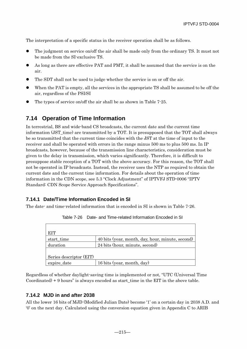
IPTVFJ STD-0004
—215—
The interpretation of a specific status in the receiver operation shall be as follows.
The judgment on service on/off the air shall be made only from the ordinary TS. It must not be made from the SI-exclusive TS.
As long as there are effective PAT and PMT, it shall be assumed that the service is on the air.
The SDT shall not be used to judge whether the service is on or off the air.
When the PAT is empty, all the services in the appropriate TS shall be assumed to be off the air, regardless of the PSI/SI
The types of service on/off the air shall be as shown in Table 7-25.
7.14 Operation of Time Information In terrestrial, BS and wide-band CS broadcasts, the current date and the current time information (JST_time) are transmitted by a TOT. It is presupposed that the TOT shall always be so transmitted that the current time coincides with the JST at the time of input to the receiver and shall be operated with errors in the range minus 500 ms to plus 500 ms. In IP broadcasts, however, because of the transmission line characteristics, consideration must be given to the delay in transmission, which varies significantly. Therefore, it is difficult to presuppose stable reception of a TOT with the above accuracy. For this reason, the TOT shall not be operated in IP broadcasts. Instead, the receiver uses the NTP as required to obtain the current date and the current time information. For details about the operation of time information in the CDN scope, see 5.3 “Clock Adjustment” of IPTVFJ STD-0006 “IPTV Standard: CDN Scope Service Approach Specifications”.
7.14.1 Date/Time Information Encoded in SI The date- and time-related information that is encoded in SI is shown in Table 7-26.
Table 7-26 Date- and Time-related Information Encoded in SI
EIT start_time 40 bits (year, month, day, hour, minute, second) duration 24 bits (hour, minute, second) Series descriptor (EIT) expire_date 16 bits (year, month, day)
Regardless of whether daylight-saving time is implemented or not, “UTC (Universal Time Coordinated) + 9 hours” is always encoded as start_time in the EIT in the above table.
7.14.2 MJD in and after 2038 All the lower 16 bits of MJD (Modified Julian Date) become ‘1’ on a certain day in 2038 A.D. and ‘0’ on the next day. Calculated using the conversion equation given in Appendix C to ARIB

IPTVFJ STD-0004
-216-
STD-B10 Part 2, the day on which all the 16 bits become ‘0’ takes us back to the 1800s. In IP broadcasts, therefore, the MJD shall be operated as follows.
Even after 2038 A.D., the conversion equation defined in Appendix C to ARIB STD-B10 Part 2 shall continue to be operated until February 28, 2100, and the lower 16 bits of the MJD value converted shall be transmitted.
At the receiver side, a reference date (e.g., the date of shipment of the receiver) shall be memorized. If the receiver receives information that is undoubtedly older than the reference date, it shall process the information assuming that the 17th bit is ‘1’.
After 2100, it is necessary to redefine the MJD conversion equation itself. At present, how the equation will be redefined is unknown.
IPTVFJ STD-0004
—217—
Details of Operation
7.15 Event Sharing Event sharing shall not be operated.
7.16 Operation of Series Event As one of applications handling programs as a group, reserving and recording, for example, a serial drama as a series can be considered.
The operation of series events is described below.
7.16.1 Descriptor Used To define a series, the series descriptor is used.
The series descriptors arranged in the EIT are transmitted as commonly operated SI.
Series descriptors are not always arranged for all events.
There are cases in which even when series descriptors are arranged in the EIT, the series name is not described. In this case, the receiver assumes that the program name described in the short event descriptor is the series name. To give a series name which is different from the program name, the series name must be described in the series descriptor.
7.16.2 Assignment of Values (1) series_id
A unique series_id is assigned to each service. For 100 days from the day following the day on which an event belonging to a certain series is broadcast last, the series_id of the series must not be assigned to a different series. If there is the same series_id in that period, it means that the event belongs to the same series.
(2) repeat_label There are cases in which a series is rebroadcast in the same period as the original broadcast. For example, there is an across-the-board drama which is originally broadcast in the morning and which is rebroadcast in the afternoon. In that case, repeat_label=0 is given to the original broadcast and repeat_label=1 is given to the rebroadcast. If there is another rebroadcast (e.g., the original drama rebroadcast over a different channel at night), repeat_label=2 is given to it. There may be one original broadcast and a maximum of 15 rebroadcasts in the same period. The value of repeat_label itself has no meaning: it is used only to distinguish between setup groups. Thus, repeat_label=1 does not mean the first rebroadcast. On the other hand, different repeat_labels clearly indicate rebroadcasts of different setup.
IPTVFJ STD-0004
-218-
From both the series_id and repeat_label, it is possible to uniquely distinguish between rebroadcasts. Basically, when the originally broadcast series is reserved, the program that is originally broadcast is to be reserved, whereas the program that is rebroadcast is to be reserved when the rebroadcast series is reserved. It should be noted, however, that since the same series_id means the same content of the program, if some other program has to be reserved at the same time, it is possible to reserve the same series of different setup. Even when a specific series is actually a rebroadcast of a series of the past, the rebroadcast may be handled as the original broadcast (repeat_label=0) unless the broadcasting periods do not overlap.
(3) program_pattern This indicates the pattern of setup of a series program. By this, it is possible to roughly estimate when the next event belonging to the series will be broadcast.
(4) expire_date_valid_flag The value of this flag is set to 0 when the date of completion of the series is not fixed.
(5) expire_date This describes the date in MJD until which the series is valid. Even if the receiver cannot recognize the last event of the series for any reason, it judges that the series is completed on that date. Said date need not necessarily be the same as the date of the final broadcast of the series: it may be some later date.
(6) episode_number The values of episode_number are in the range 0x000 (0) to 0xFFF (4095). The value “0x000” is used for news programs, etc. for which the number of episodes cannot be defined. Concerning multiple events which are given 0x000, the receiver does not recognize them as identical episodes. Ordinarily, the same episode_number is given to rebroadcasts of the number of identical episodes of a series.
(7) last_episode_number The values of last_episode_number are also in the range 0x000 (0) to 0xFFF (4095). The value 0x000 is used when the last episode number (i.e., the total number of programs) is not fixed. The event is the last one of the series when the last_episode_number is not 0 and the episode_number and last_episode_number are the same. For a program series with more than 4,095 episodes, it shall be divided into two (or more) series.
7.16.3 Termination of Series See ARIB TR-B15.
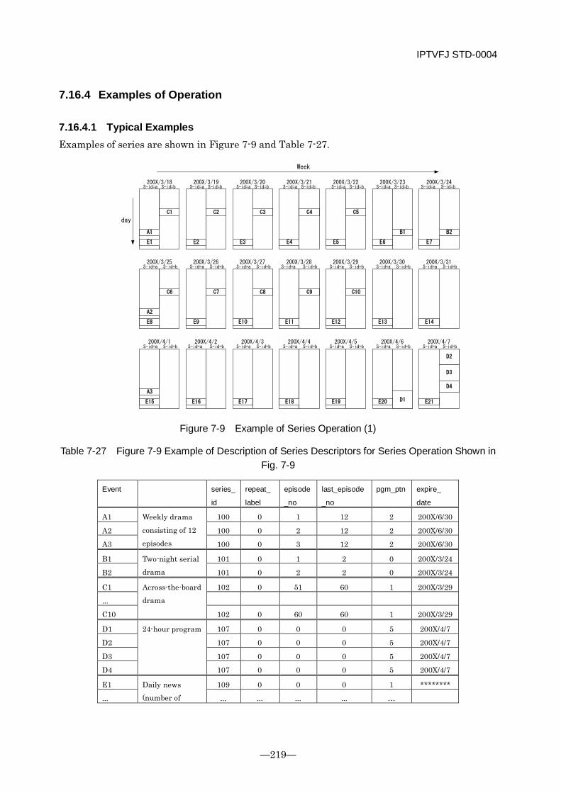
IPTVFJ STD-0004
—219—
7.16.4 Examples of Operation
7.16.4.1 Typical Examples Examples of series are shown in Figure 7-9 and Table 7-27.
A1
Week
day
S-id=a S-id=b S-id=a S-id=bS-id=a S-id=bS-id=a S-id=bS-id=a S-id=bS-id=a S-id=bS-id=a S-id=b
A2
S-id=a S-id=b S-id=aS-id=a S-id=bS-id=a S-id=bS-id=a S-id=bS-id=a S-id=bS-id=a S-id=b
S-id=a
A3
S-id=a S-id=b S-id=aS-id=a S-id=bS-id=a S-id=bS-id=a S-id=bS-id=a S-id=bS-id=a S-id=b
S-id=b
S-id=b
200X/3/18 200X/3/19 200X/3/20 200X/3/21 200X/3/22 200X/3/23 200X/3/24
200X/3/25 200X/3/26 200X/3/27 200X/3/28 200X/3/29 200X/3/30 200X/3/31
200X/4/1 200X/4/2 200X/4/3 200X/4/4 200X/4/5 200X/4/6 200X/4/7
B1 B2
C1 C2 C3 C4 C5
C6 C7 C8 C9 C10
D2
D1
D3
D4
E1 E2 E3 E4 E5 E6 E7
E8 E9 E10 E11 E12 E13 E14
E15 E16 E17 E18 E19 E20 E21
Figure 7-9 Example of Series Operation (1)
Table 7-27 Figure 7-9 Example of Description of Series Descriptors for Series Operation Shown in Fig. 7-9
Event series_
id
repeat_
label
episode
_no
last_episode
_no
pgm_ptn expire_
date
A1 Weekly drama consisting of 12 episodes
100 0 1 12 2 200X/6/30
A2 100 0 2 12 2 200X/6/30
A3 100 0 3 12 2 200X/6/30
B1 Two-night serial drama
101 0 1 2 0 200X/3/24
B2 101 0 2 2 0 200X/3/24
C1 Across-the-board drama
102 0 51 60 1 200X/3/29
...
C10 102 0 60 60 1 200X/3/29
D1 24-hour program 107 0 0 0 5 200X/4/7
D2 107 0 0 0 5 200X/4/7
D3 107 0 0 0 5 200X/4/7
D4 107 0 0 0 5 200X/4/7
E1 Daily news (number of
109 0 0 0 1 ********
... ... ... ... ... …
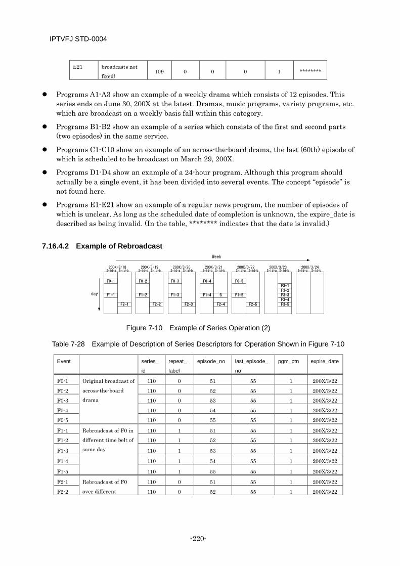
IPTVFJ STD-0004
-220-
E21 broadcasts not fixed)
109 0 0 0 1 ********
Programs A1-A3 show an example of a weekly drama which consists of 12 episodes. This
series ends on June 30, 200X at the latest. Dramas, music programs, variety programs, etc. which are broadcast on a weekly basis fall within this category.
Programs B1-B2 show an example of a series which consists of the first and second parts (two episodes) in the same service.
Programs C1-C10 show an example of an across-the-board drama, the last (60th) episode of which is scheduled to be broadcast on March 29, 200X.
Programs D1-D4 show an example of a 24-hour program. Although this program should actually be a single event, it has been divided into several events. The concept “episode” is not found here.
Programs E1-E21 show an example of a regular news program, the number of episodes of which is unclear. As long as the scheduled date of completion is unknown, the expire_date is described as being invalid. (In the table, ******** indicates that the date is invalid.)
7.16.4.2 Example of Rebroadcast Week
day
S-id=a S-id=b S-id=a S-id=bS-id=a S-id=bS-id=a S-id=bS-id=a S-id=bS-id=a S-id=bS-id=a S-id=b200X/3/18 200X/3/19 200X/3/20 200X/3/21 200X/3/22 200X/3/23 200X/3/24
F0-1 F0-2 F0-3 F0-4 F0-5
F1-1 F1-2 F1-3
F2-3F2-2F2-1
F1-4
F2-4
F1-5
F2-5
F3-1F3-2F3-3F3-4F3-5
G
Figure 7-10 Example of Series Operation (2)
Table 7-28 Example of Description of Series Descriptors for Operation Shown in Figure 7-10
Event series_
id
repeat_
label
episode_no last_episode_
no
pgm_ptn expire_date
F0-1 Original broadcast of across-the-board drama
110 0 51 55 1 200X/3/22
F0-2 110 0 52 55 1 200X/3/22
F0-3 110 0 53 55 1 200X/3/22
F0-4 110 0 54 55 1 200X/3/22
F0-5 110 0 55 55 1 200X/3/22
F1-1 Rebroadcast of F0 in different time belt of same day
110 1 51 55 1 200X/3/22
F1-2 110 1 52 55 1 200X/3/22
F1-3 110 1 53 55 1 200X/3/22
F1-4 110 1 54 55 1 200X/3/22
F1-5 110 1 55 55 1 200X/3/22
F2-1 Rebroadcast of F0 over different
110 0 51 55 1 200X/3/22
F2-2 110 0 52 55 1 200X/3/22
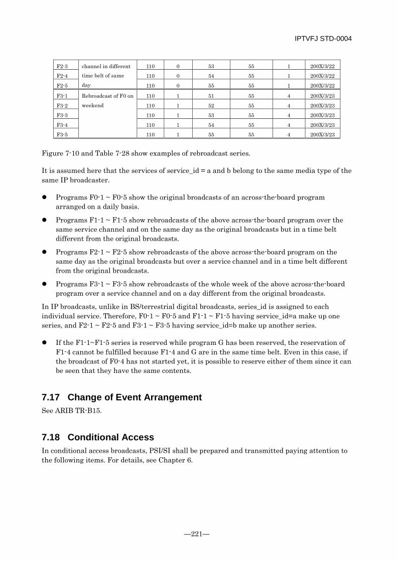
IPTVFJ STD-0004
—221—
F2-3 channel in different time belt of same day
110 0 53 55 1 200X/3/22
F2-4 110 0 54 55 1 200X/3/22
F2-5 110 0 55 55 1 200X/3/22
F3-1 Rebroadcast of F0 on weekend
110 1 51 55 4 200X/3/23
F3-2 110 1 52 55 4 200X/3/23
F3-3 110 1 53 55 4 200X/3/23
F3-4 110 1 54 55 4 200X/3/23
F3-5 110 1 55 55 4 200X/3/23
Figure 7-10 and Table 7-28 show examples of rebroadcast series.
It is assumed here that the services of service_id = a and b belong to the same media type of the same IP broadcaster.
Programs F0-1 ~ F0-5 show the original broadcasts of an across-the-board program arranged on a daily basis.
Programs F1-1 ~ F1-5 show rebroadcasts of the above across-the-board program over the same service channel and on the same day as the original broadcasts but in a time belt different from the original broadcasts.
Programs F2-1 ~ F2-5 show rebroadcasts of the above across-the-board program on the same day as the original broadcasts but over a service channel and in a time belt different from the original broadcasts.
Programs F3-1 ~ F3-5 show rebroadcasts of the whole week of the above across-the-board program over a service channel and on a day different from the original broadcasts.
In IP broadcasts, unlike in BS/terrestrial digital broadcasts, series_id is assigned to each individual service. Therefore, F0-1 ~ F0-5 and F1-1 ~ F1-5 having service_id=a make up one series, and F2-1 ~ F2-5 and F3-1 ~ F3-5 having service_id=b make up another series.
If the F1-1~F1-5 series is reserved while program G has been reserved, the reservation of F1-4 cannot be fulfilled because F1-4 and G are in the same time belt. Even in this case, if the broadcast of F0-4 has not started yet, it is possible to reserve either of them since it can be seen that they have the same contents.
7.17 Change of Event Arrangement See ARIB TR-B15.
7.18 Conditional Access In conditional access broadcasts, PSI/SI shall be prepared and transmitted paying attention to the following items. For details, see Chapter 6.

IPTVFJ STD-0004
-222-
7.18.1 Specifying EMM Stream In IP broadcasts, the EMM stream shall not be operated. Instead, the main license that corresponds to the EMM operated in BS digital broadcasts/terrestrial digital broadcasts shall be acquired from the CAS server by communication.
7.18.2 Setting Billing Unit for Program The setting of a billing unit and the relationships between billing unit and ECM and between ECM and scramble are described below.
Setting billing unit • Only one billing unit can be set for each program.
Relationship between billing unit and ECM • One ECM is associated with each billing unit.
Relationship between ECM and scramble • The ES that is associated with an ECM has been scrambled. • It should be noted, however, that when a transient response or filler is inserted between
programs at the transmitting side, the ES is not always scrambled even when it is associated with an ECM. Whether or not a specific component has been scrambled is indicated by the transport_scrambling_control field in the TS packet header.
From the standpoint of billing, programs are defined and classified as follows.
Free programs: Programs whose default ES group is not chargeable. • In IP broadcasts, all ES belonging to free programs are not chargeable.
Pay programs: Programs whose default ES group is chargeable. • For all ES, the same billing unit (ECM) must be set.
The default ES group in conditional access broadcasts is defined for each service_type (see Table 7-55) in consideration of the object of billing. It is shown in Table 7-29.
Table 7-29 Default ES Groups in Conditional Access Broadcasts
service_type Content Default ES group 0x01 Digital TV service Video default ES (component_tag=0x00),
Audio default ES (component_tag=0x10) 0x80
Video service for adults Video default ES (component_tag=0x00),
Audio default ES (component_tag=0x10) Services other than those shown above are not charged. Therefore, no default ES groups are defined for them.
IPTVFJ STD-0004
—223—
7.18.2.1 PMT When scrambling the PMT to charge for a program, a conditional access descriptor shall be arranged to specify an effective ECM. The specifications for descriptor arrangement are as follows.
(1) For a pay program, a conditional access descriptor specifying an effective ECM shall be arranged in the first loop.
(2) The conditional access descriptor shall not be arranged in the second loop.
7.18.2.2 SDT/EIT Concerning the SDT/EIT, in consideration of convenience during program reservation, etc., the free_CA_mode field shall be operated in IP broadcasts as follows to distinguish between free and pay programs.
0: Free program
1: Pay program
The specifications for setting the field are as follows.
In the SDT, a value for identification of free/pay programs determined by the provider for its service channel shall be set.
For example, for a flat/tier contract service channel which ordinarily broadcasts pay programs, the appropriate field of the SDT shall be set to “1”. This value shall not be changed even if free programs are broadcast in a certain period or time belt within the channel.
In the EIT, values for identification of free/pay programs must be set for individual programs.
Therefore, the receiver shall judge whether a specific program is free or pay on the basis of the value set in the EIT: it shall not use the SDT for this purpose.
7.18.3 Setting Information for Confirmation of Reservation of Viewing (Recording)
In the reservation of viewing (recording) of a pay program, the receiver uses the CA contract info descriptor to present the viewer with information about whether or not the program can be viewed (recorded). This descriptor shall be described paying attention to the following items.
In IP broadcasts, only the flat/tier billing for each service channel shall be operated. In IP broadcasts, only one billing unit shall be set. In the CA contract info descriptor,
only CA_unit_id=0x01 can be specified. In IP broadcasts, charge names must not be described because the PPV system is not
operated.
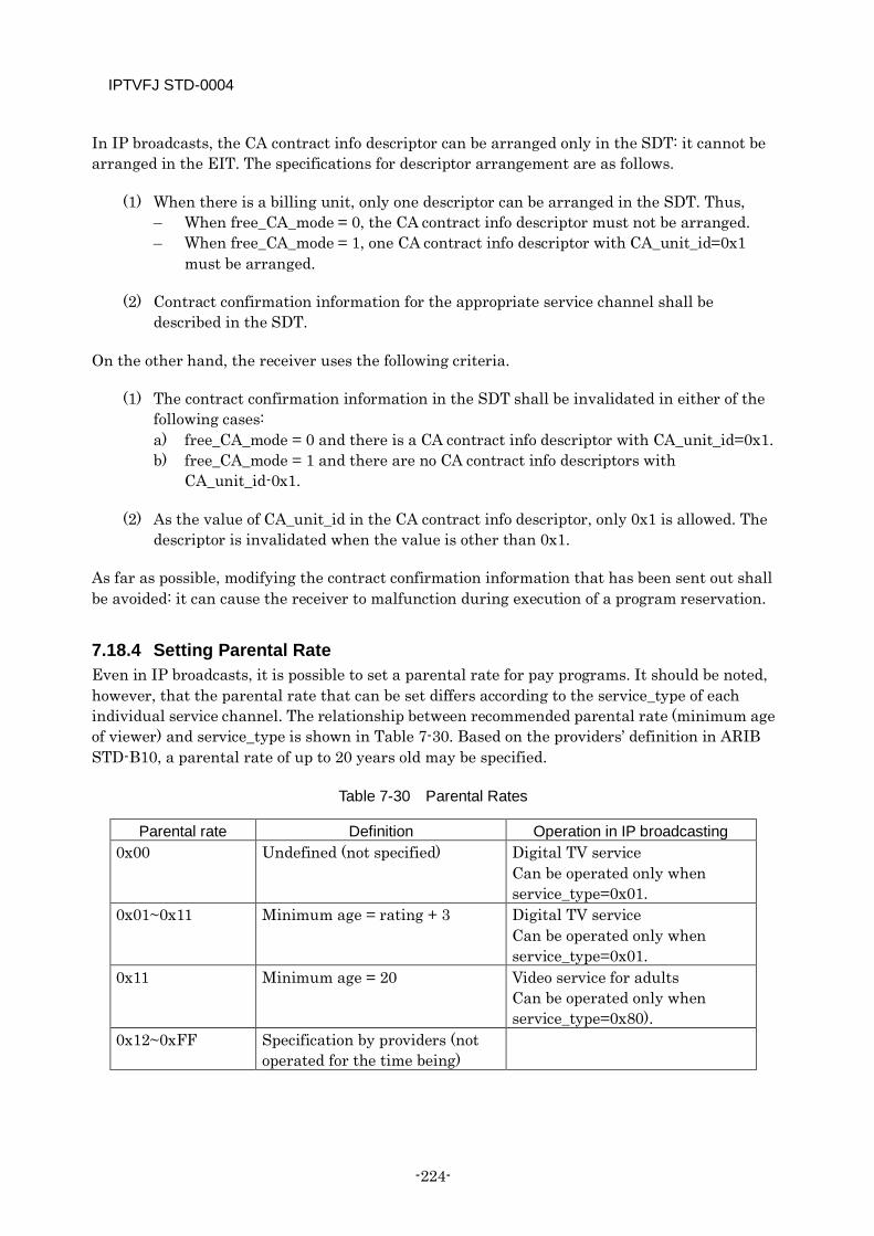
IPTVFJ STD-0004
-224-
In IP broadcasts, the CA contract info descriptor can be arranged only in the SDT: it cannot be arranged in the EIT. The specifications for descriptor arrangement are as follows.
(1) When there is a billing unit, only one descriptor can be arranged in the SDT. Thus, – When free_CA_mode = 0, the CA contract info descriptor must not be arranged. – When free_CA_mode = 1, one CA contract info descriptor with CA_unit_id=0x1
must be arranged.
(2) Contract confirmation information for the appropriate service channel shall be described in the SDT.
On the other hand, the receiver uses the following criteria.
(1) The contract confirmation information in the SDT shall be invalidated in either of the following cases: a) free_CA_mode = 0 and there is a CA contract info descriptor with CA_unit_id=0x1. b) free_CA_mode = 1 and there are no CA contract info descriptors with
CA_unit_id-0x1.
(2) As the value of CA_unit_id in the CA contract info descriptor, only 0x1 is allowed. The descriptor is invalidated when the value is other than 0x1.
As far as possible, modifying the contract confirmation information that has been sent out shall be avoided: it can cause the receiver to malfunction during execution of a program reservation.
7.18.4 Setting Parental Rate Even in IP broadcasts, it is possible to set a parental rate for pay programs. It should be noted, however, that the parental rate that can be set differs according to the service_type of each individual service channel. The relationship between recommended parental rate (minimum age of viewer) and service_type is shown in Table 7-30. Based on the providers’ definition in ARIB STD-B10, a parental rate of up to 20 years old may be specified.
Table 7-30 Parental Rates
Parental rate Definition Operation in IP broadcasting 0x00 Undefined (not specified) Digital TV service
Can be operated only when service_type=0x01.
0x01~0x11 Minimum age = rating + 3 Digital TV service Can be operated only when service_type=0x01.
0x11 Minimum age = 20 Video service for adults Can be operated only when service_type=0x80).
0x12~0xFF Specification by providers (not operated for the time being)

IPTVFJ STD-0004
—225—
It should be noted that a parental rate is set for each program: it must not be set for a specific component.
In these Specifications, the parental rate control shall be implemented in accordance with the following specifications.
(1) The parental rate shall be described only in the first byte of the private_data_byte area of the conditional access descriptor that is arranged in the 1st loop of the PMT.
(2) The parental rate shall be described in the rating field of the parental rate descriptor that is arranged in the EIT. It should be noted, however, that the same parental rate descriptor must be arranged in both the EIT[p/f actual] and the EIT[schedule other basic] of the appropriate program.
As far as possible, re-setting a parental rate once sent out should be avoided.
For details about the operation performed by the receiver when it recognizes a set parental rate, see Chapter 3.
7.18.5 Setting Billing Unit for Multi-view TV In IP broadcasts, multi-view TV is not operated.
7.18.6 Setting Control for Display of Automatically Displayed Messages In IP broadcasts, automatically displayed messages are not operated.
7.18.7 Setting Link to CA Alternative Service In IP broadcasts, the CA alternative services using the link descriptor, like those which are implemented in BS/wide-band CS/terrestrial broadcasts, are not operated. Instead, during selection of a non-contracted channel after the basic registration, the receiver is guided to the provider’s portal using the hyperlink descriptor of the BIT. For details, see 3.2.7 of these Specifications and 6.5.3.3 “Operation of Portal Access Following Pushing d Button While Viewing IP Broadcasting Service” of IPTVFJ STD-0006 “IPTV Standard: CDN Scope Service Approach Specifications”.
7.19 Digital Copy Control Each broadcaster uses the digital copy control descriptor and the content availability descriptor to transmit to the receiver and digital recorder the information about digital recording of programs and signal output conditions. The digital copy control descriptor specifies digital copy control information for the high-speed digital interface compatible with the DTCP, the maximum transmission rate used in the judgment on whether or not a specific program can be recorded and in the selection of a recording mode, etc. The content availability descriptor specifies the condition of encryption of output signals.
IPTVFJ STD-0004
-226-
The digital copy control descriptor can be arranged in the 1st loop of the PMT, the SDT and the EIT. The basic copy control shall be implemented in accordance with Annex F “Example of service provider define bit of digital copy control descriptor” to ARIB STD-B10. Detailed operation of copy control is explained in the subsection dealing with the digital copy control descriptor.
7.19.1 Order of Priority for Copy Control Information The information that is provided by the digital copy control descriptor arranged in the PMT is used when a program is actually recorded, and the copy control information that is described in the EIT is used when preparing for the recording of a program. If the copy control information is not described in the EIT but the digital copy control descriptor is arranged in the SDT, the content of the descriptor in the SDT shall be applied.
The final copy control is implemented in accordance with the content of the description in the PMT. When implementing copy control which is not the default one (see the next subsection), a digital copy control descriptor must also be arranged in the PMT. It should be noted that the final copy control of a pay program shall be implemented with reference to the copy control information described in the appropriate ECM.
The information provided by the digital copy control descriptor arranged in the SDT and the EIT, respectively, is used when the recording of an event is reserved. To specify copy control information for the entire service under consideration, the digital copy control descriptor shall be arranged in the SDT. When specifying copy control information for a specific event, the digital copy control descriptor shall be arranged in the EIT. If the copy control information is described in both the SDT and the EIT, preference shall be given to the content of the EIT.
7.19.2 Default Digital Copy Control Information The default digital copy control information when the digital copy control descriptor is not described in any of the PMT, SDT and EIT shall be equivalent to “copy is allowed without any restrictions”, that is, copy_control_type=‘01’ and digital_recording_control_data=‘00’ in digital TV service, promotion video service and video service for adults.
As already mentioned, the final copy control is implemented in accordance with the content of description in the PMT (ECM in the case of a pay program). It should be noted, therefore, that no matter what digital copy control information is contained in the EIT and SDT, “copy is allowed” is the final result unless a digital copy control descriptor not specifying “copy is allowed without any restrictions” is inserted in the PMT (ECM in the case of a pay program). In any case, as a basic matter, there must not be any inconsistency in information between SI (SDT and EIT) and PSI (PMT) and ECM in the case of a pay program.
7.19.3 Information About Maximum Transmission Rate In maximum_bit_rate of the digital copy control descriptor, a rough value rounded up in increments of 1/4 Mbps for each event is described. For example, “0x24” is described as maximum_bit_rate, it means that the maximum transmission rate is 9 Mbps. When the transmission rate is variable, the maximum rate shall be described. The maximum transmission
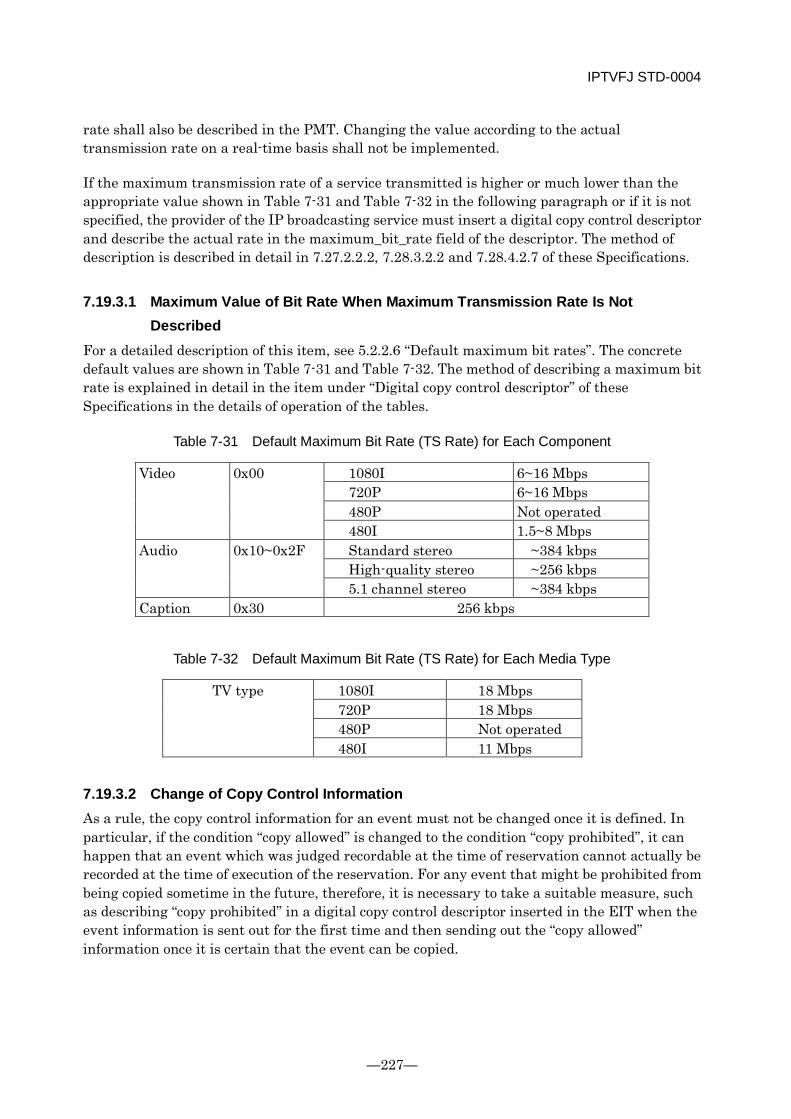
IPTVFJ STD-0004
—227—
rate shall also be described in the PMT. Changing the value according to the actual transmission rate on a real-time basis shall not be implemented.
If the maximum transmission rate of a service transmitted is higher or much lower than the appropriate value shown in Table 7-31 and Table 7-32 in the following paragraph or if it is not specified, the provider of the IP broadcasting service must insert a digital copy control descriptor and describe the actual rate in the maximum_bit_rate field of the descriptor. The method of description is described in detail in 7.27.2.2.2, 7.28.3.2.2 and 7.28.4.2.7 of these Specifications.
7.19.3.1 Maximum Value of Bit Rate When Maximum Transmission Rate Is Not Described
For a detailed description of this item, see 5.2.2.6 “Default maximum bit rates”. The concrete default values are shown in Table 7-31 and Table 7-32. The method of describing a maximum bit rate is explained in detail in the item under “Digital copy control descriptor” of these Specifications in the details of operation of the tables.
Table 7-31 Default Maximum Bit Rate (TS Rate) for Each Component
Video 0x00 1080I 6~16 Mbps 720P 6~16 Mbps 480P Not operated 480I 1.5~8 Mbps
Audio 0x10~0x2F Standard stereo ~384 kbps High-quality stereo ~256 kbps 5.1 channel stereo ~384 kbps
Caption 0x30 256 kbps
Table 7-32 Default Maximum Bit Rate (TS Rate) for Each Media Type
TV type 1080I 18 Mbps 720P 18 Mbps 480P Not operated 480I 11 Mbps
7.19.3.2 Change of Copy Control Information As a rule, the copy control information for an event must not be changed once it is defined. In particular, if the condition “copy allowed” is changed to the condition “copy prohibited”, it can happen that an event which was judged recordable at the time of reservation cannot actually be recorded at the time of execution of the reservation. For any event that might be prohibited from being copied sometime in the future, therefore, it is necessary to take a suitable measure, such as describing “copy prohibited” in a digital copy control descriptor inserted in the EIT when the event information is sent out for the first time and then sending out the “copy allowed” information once it is certain that the event can be copied.
IPTVFJ STD-0004
-228-
For the same reason as mentioned above, the content of the copy control information described in the SDT must not be changed easily. This is because there are cases in which the recording of a program is reserved based on the information described in the SDT when the EIT has no digital copy control descriptors. When changing the copy control information described in the SDT, it is necessary to make sure that no programs will be reserved based on the copy control information of the SDT by inserting a digital copy control descriptor in the EIT for each of all programs to be newly sent out, a maximum of N days (when transmission of N days of information is indicated in SI) prior to the planned change.
7.19.4 Content Output Control By using encryption_mode in the content availability descriptor, each broadcaster can control the output of “copy allowed” contents from its high-speed digital interface. The content availability descriptor can be inserted only in the 1st loop of the PMT. For details about the control of output of contents, see [Appendix B] to these Specifications.
7.19.4.1 Default Output Control The content availability descriptor is used in combination with the copy control information described in the digital copy control descriptor. Therefore, in the absence of a digital copy control descriptor, the content availability descriptor is invalid. The default output control when neither a content availability descriptor nor a digital copy control descriptor is inserted in the 1st loop of the PMT is encryption_mode=1 (output is not protected).
7.19.4.2 Output Protection The encryption_mode is valid for output from a high-speed digital interface when copy_control_type in the digital copy control descriptor is “01” and digital_recording_control_data indicates that “copy is allowed without any restrictions”. The default copy control information in the absence of a digital copy control descriptor can also be interpreted as one of those conditions. Without a digital copy control descriptor, the content availability descriptor cannot be valid. Therefore, in order to specify encryption_mode, it is absolutely necessary to insert the digital copy control descriptor that clearly shows the above conditions.
For a detailed description of the operation of encryption_mode, see [Appendix B] to these Specifications and the DTCP Specifications.
7.19.5 Temporary Storage of Content The concept of temporary storage is meaningful only when the copy control information indicates “copy prohibited”.
Even when the copy control information indicates “copy prohibited”, it is possible to temporarily store the content for a certain period of time.
IPTVFJ STD-0004
—229—
Although ARIB STD-B10 defines several different times allowed for temporary storage, only “one hour and 30 minutes” (retention_mode = “0” and retention_state = “111”) is defined in these Specifications.
For a detailed description of temporary storage, see [Appendix B].
7.20 Extraordinary Services No extraordinary services shall be operated.
7.21 Event Relay The event relay shall not be operated.
7.22 Multi-view Television (MVTV) Multi-view television shall not be operated.
7.23 Emergency Warning Broadcast Emergency warning broadcast shall not be operated.
7.24 Operation of PSI/SI in Caption Broadcast See ARIB TR-B15.
7.25 Operation of Daylight-saving Time In IP broadcasts, the TOT and the local time offset descriptor contained in it shall not be operated. For the operation of IP broadcast time information and daylight-saving time in the CDN scope, see the item under “Time information” in 5.3 “Clock Adjustment” of IPTVFJ STD-0006 “IPTV Standard: CDN-scope Service Approach Specifications”.
7.26 Change of Service/TS Configuration Since the definition of a service is very important from the standpoint of interface with the viewer, it shall not be changed easily. Thus, ordinarily, the definitions of service/TS are almost fixed.
However, under certain circumstances (e.g., network reorganization), the following cases are conceivable.
Service addition, deletion or relocation from one TS to another
TS addition or deletion
IPTVFJ STD-0004
-230-
TS delivery address change
It should be noted that the service type of a specific service shall not be changed.
7.26.1 Service Addition/Deletion/Relocation between TSes When a service is added, deleted or moved between TSes, it can be judged from the service list descriptor in the NIT. Namely, if a certain service has disappeared from the service list for each TS at the time the NIT is updated, it indicates that said service has been deleted. If some new service has been found in the service list, it indicates that said service has been added. The movement of a service between TSes indicates service addition and service deletion that take place concurrently. Namely, only the condition where the same service_id as the one that was defined in certain TS has been defined in another TS after updating of the NIT is regarded as service movement between TSes.
Since the NIT cannot always be monitored constantly, there can be cases in which it is impossible to determine whether a specific service has been re-added after it was deleted once or has been moved to the current TS from some other TS. In view of such a situation, any service provider that wants to reuse a service_id that has been deleted for a similar or different service is prohibited from defining said service_id for at least 32 days from the day on which it was deleted (uniqueness of service_id on a certain time axis).
When the NIT is updated, the related SI information shall also be updated almost concurrently. Due to the difference in transmission period, etc., there is the possibility that a temporary inconsistency in information will occur when the information is updated. Here, the inconsistency means the condition in which the SDT and EIT are not transmitted while they are described in the NIT or vice versa. In addition, during the movement of a service between TSes, it can happen that SDT and EIT of the same service_id are transmitted temporarily under a different TS ID.
When adding a service, the service shall be entered in the NIT service list and described in the SDT. At the same time, transmission of the necessary EIT shall be started. The service provider may freely decide how many days before start of the broadcasting the service is to be defined.
When deleting a service, the service shall be deleted from the NIT service list and the service description shall be deleted from the SDT. At the same time, transmission of the relevant EIT shall be terminated. Before deleting the service, broadcasting of the program shall be terminated and the service shall be suspended. After the service deletion, no events shall be set.
When moving a service between TSes, the service shall be relocated in the NIT service list and the content of the service description in the SDT shall be changed. At the same time, transmission of the old EIT shall be terminated and transmission of the new EIT shall be started. All this shall be done after broadcasting of the program is terminated and the service is suspended. No events extending beyond the time of the service movement between TSes shall be set. It should be noted that even when a service is moved between TSes, the event that is defined in the service is valid. It is advisable for the receiver not to refer to the transport_stream_id in confirming a specific event, etc.
IPTVFJ STD-0004
—231—
7.26.2 Addition/Deletion of TS The presence or absence of a TS added or deleted shall be judged from the TS loop in the NIT.
When a TS is added, transmission of the entire PSI/SI, including the PAT and NIT, might stop temporarily.
When deleting a TS, all the services shall be deleted or relocated beforehand.
7.26.3 Relocation of TS Delivery Address The relocation of a multicast address for delivery of a TS and a source address when MLDv2 is used shall be judged from the IP delivery system descriptor in the NIT. Prior to the relocation, broadcasting of programs in all the services within the TS shall be terminated and the services shall be suspended. Events which extend over the time of relocation of the multicast address and source address for the delivery of a TS shall not be set.
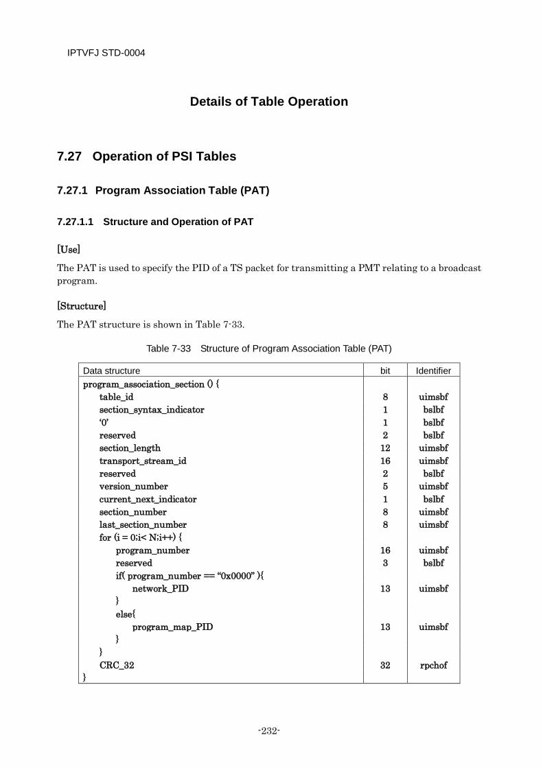
IPTVFJ STD-0004
-232-
Details of Table Operation
7.27 Operation of PSI Tables
7.27.1 Program Association Table (PAT)
7.27.1.1 Structure and Operation of PAT
[Use]
The PAT is used to specify the PID of a TS packet for transmitting a PMT relating to a broadcast program.
[Structure]
The PAT structure is shown in Table 7-33.
Table 7-33 Structure of Program Association Table (PAT)
Data structure bit Identifier program_association_section () {
table_id 8 uimsbf section_syntax_indicator 1 bslbf ‘0’ 1 bslbf reserved 2 bslbf section_length 12 uimsbf transport_stream_id 16 uimsbf reserved 2 bslbf version_number 5 uimsbf current_next_indicator 1 bslbf section_number 8 uimsbf last_section_number 8 uimsbf for (i = 0;i< N;i++) {
program_number 16 uimsbf reserved 3 bslbf if( program_number == “0x0000” ){
network_PID 13 uimsbf } else{
program_map_PID 13 uimsbf }
} CRC_32 32 rpchof
}
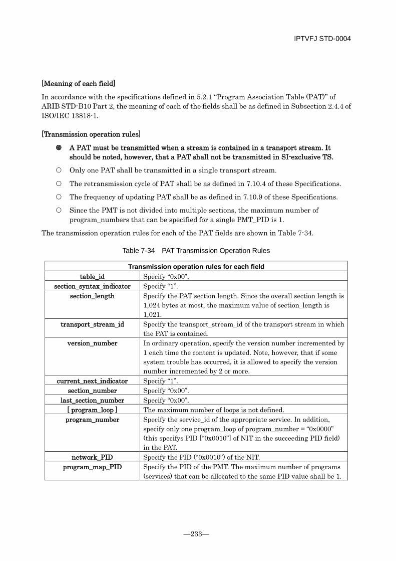
IPTVFJ STD-0004
—233—
[Meaning of each field]
In accordance with the specifications defined in 5.2.1 “Program Association Table (PAT)” of ARIB STD-B10 Part 2, the meaning of each of the fields shall be as defined in Subsection 2.4.4 of ISO/IEC 13818-1.
[Transmission operation rules]
A PAT must be transmitted when a stream is contained in a transport stream. It should be noted, however, that a PAT shall not be transmitted in SI-exclusive TS.
Only one PAT shall be transmitted in a single transport stream.
The retransmission cycle of PAT shall be as defined in 7.10.4 of these Specifications.
The frequency of updating PAT shall be as defined in 7.10.9 of these Specifications.
Since the PMT is not divided into multiple sections, the maximum number of program_numbers that can be specified for a single PMT_PID is 1.
The transmission operation rules for each of the PAT fields are shown in Table 7-34.
Table 7-34 PAT Transmission Operation Rules
Transmission operation rules for each field table_id Specify “0x00”.
section_syntax_indicator Specify “1”. section_length Specify the PAT section length. Since the overall section length is
1,024 bytes at most, the maximum value of section_length is 1,021.
transport_stream_id Specify the transport_stream_id of the transport stream in which the PAT is contained.
version_number In ordinary operation, specify the version number incremented by 1 each time the content is updated. Note, however, that if some system trouble has occurred, it is allowed to specify the version number incremented by 2 or more.
current_next_indicator Specify “1”. section_number Specify “0x00”.
last_section_number Specify “0x00”. [ program_loop ] The maximum number of loops is not defined. program_number Specify the service_id of the appropriate service. In addition,
specify only one program_loop of program_number = “0x0000” (this specifys PID [“0x0010”] of NIT in the succeeding PID field) in the PAT.
network_PID Specify the PID (“0x0010”) of the NIT. program_map_PID Specify the PID of the PMT. The maximum number of programs
(services) that can be allocated to the same PID value shall be 1.

IPTVFJ STD-0004
-234-
[Reception processing criteria]
If the receiver cannot receive a PAT, it determines that the transport stream does not contain any receivable stream or that the transmission system is not operating normally.
If the information of the service described in the NIT is not described in the PAT, the receiver determines that the service is dormant.
The receiving process standardsreception processing criteria for each of the PAT fields are shown in Table 7-35.
Table 7-35 Reception processing criteria for PAT
Reception processing criteria for each field table_id = “0x00”: The table is determined to be a PAT.
section_syntax_indicator = “0”: The section is determined invalid. = “1”: The section is determined valid.
section_length ≤ 1021: The length of the section. > 1021: The section is determined invalid.
transport_stream_id This is determined to be the ID of the transport stream that contains the PAT.
version_number If this has changed, the PAT is determined to have been updated. current_next_indicator = “0”: The section is determined invalid.
= “1”: The section is determined valid. section_number 0x00: The section is determined valid.
≠ 0x00: The section is determined invalid. last_section_number = 0x00: The section is determined valid.
≠ 0x00: The section is determined invalid. [ loop ]
program_number This is determined to be the service_id that is contained in the appropriate transport stream. If a service described in the NIT is not described in the PAT, it indicates that the service is dormant (see 7.13).
network_PID program_map_PID
[Other items that are worth special mention]
None

IPTVFJ STD-0004
—235—
7.27.2 Program Map Table (PMT)
7.27.2.1 Structure And Operation of PMT
[Use]
The PMT is used to specify the PID of a TS packet for transmitting each encoded signal which make up a broadcast program.
[Structure]
The PMT structure is shown in Table 7-36.
Table 7-36 Structure of Program Map Table (PMT)
Data structure bit Identifier program_map_section () {
table_id 8 uimsbf section_syntax_indicator 1 bslbf ‘0’ 1 bslbf reserved 2 bslbf section_length 12 uimsbf program_number 16 uimsbf reserved 2 bslbf version_number 5 uimsbf current_next_indicator 1 bslbf section_number 8 uimsbf last_section_number 8 uimsbf reserved 3 bslbf PCR_PID 13 uimsbf reserved 4 bslbf program_info_length 12 uimsbf for (i = 0;i< N;i++) {
descriptor() } for (i = 0;i< N;i++) {
stream_type 8 uimsbf reserved 3 bslbf elementary_PID 13 uimsbf reserved 4 bslbf ES_info_length 12 uimsbf for (j = 0;j< M;j++) {
descriptor() }
} CRC_32 32 rpchof
}
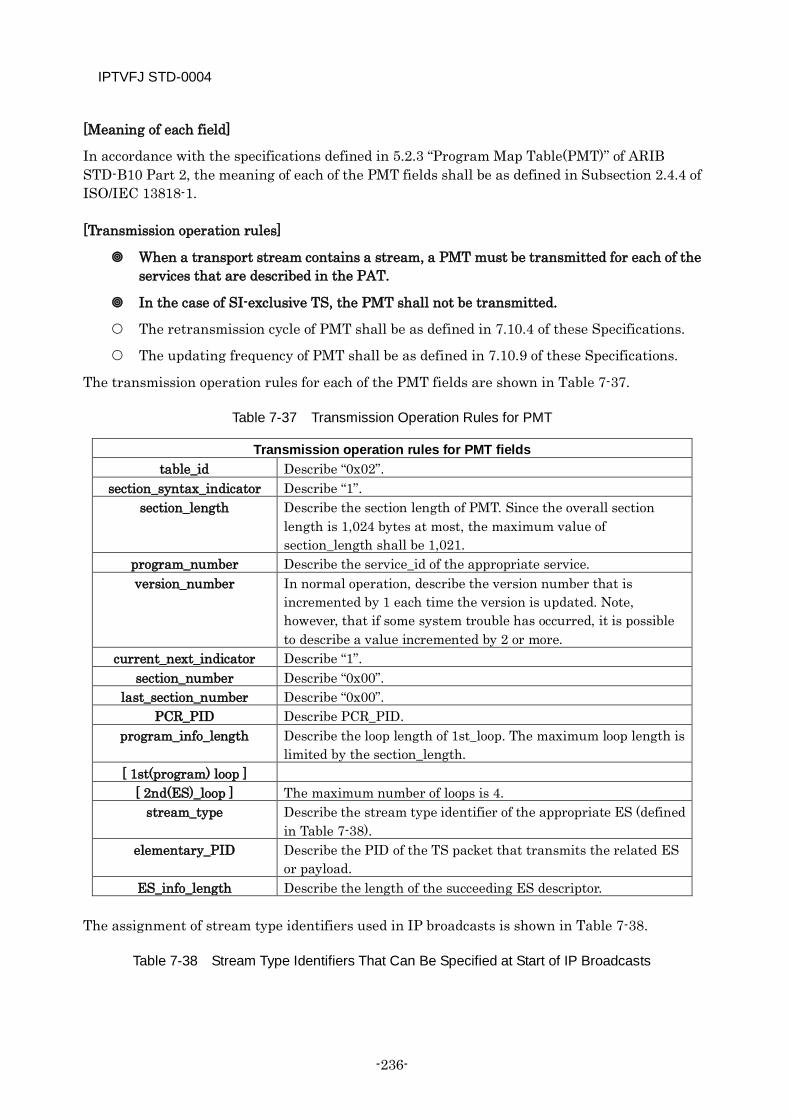
IPTVFJ STD-0004
-236-
[Meaning of each field]
In accordance with the specifications defined in 5.2.3 “Program Map Table(PMT)” of ARIB STD-B10 Part 2, the meaning of each of the PMT fields shall be as defined in Subsection 2.4.4 of ISO/IEC 13818-1.
[Transmission operation rules]
When a transport stream contains a stream, a PMT must be transmitted for each of the services that are described in the PAT.
In the case of SI-exclusive TS, the PMT shall not be transmitted.
The retransmission cycle of PMT shall be as defined in 7.10.4 of these Specifications.
The updating frequency of PMT shall be as defined in 7.10.9 of these Specifications.
The transmission operation rules for each of the PMT fields are shown in Table 7-37.
Table 7-37 Transmission Operation Rules for PMT
Transmission operation rules for PMT fields table_id Describe “0x02”.
section_syntax_indicator Describe “1”. section_length Describe the section length of PMT. Since the overall section
length is 1,024 bytes at most, the maximum value of section_length shall be 1,021.
program_number Describe the service_id of the appropriate service. version_number In normal operation, describe the version number that is
incremented by 1 each time the version is updated. Note, however, that if some system trouble has occurred, it is possible to describe a value incremented by 2 or more.
current_next_indicator Describe “1”. section_number Describe “0x00”.
last_section_number Describe “0x00”. PCR_PID Describe PCR_PID.
program_info_length Describe the loop length of 1st_loop. The maximum loop length is limited by the section_length.
[ 1st(program) loop ] [ 2nd(ES)_loop ] The maximum number of loops is 4.
stream_type Describe the stream type identifier of the appropriate ES (defined in Table 7-38).
elementary_PID Describe the PID of the TS packet that transmits the related ES or payload.
ES_info_length Describe the length of the succeeding ES descriptor. The assignment of stream type identifiers used in IP broadcasts is shown in Table 7-38.
Table 7-38 Stream Type Identifiers That Can Be Specified at Start of IP Broadcasts
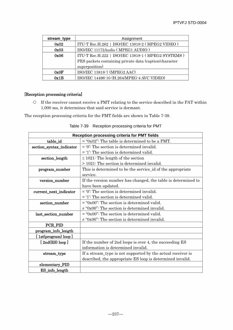
IPTVFJ STD-0004
—237—
stream_type Assignment 0x02 ITU-T Rec.H.262 | ISO/IEC 13818-2 ( MPEG2 VIDEO ) 0x03 ISO/IEC 11172Audio ( MPEG1 AUDIO ) 0x06 ITU-T Rec.H.222 | ISO/IEC 13818-1 ( MPEG2 SYSTEMS )
PES packets containing private data (caption/character superposition)
0x0F ISO/IEC 13818-7 (MPEG2 AAC) 0x1B ISO/IEC 14496-10 (H.264/MPEG-4 AVC VIDEO)
[Reception processing criteria]
If the receiver cannot receive a PMT relating to the service described in the PAT within 1,000 ms, it determines that said service is dormant.
The reception processing criteria for the PMT fields are shown in Table 7-39.
Table 7-39 Reception processing criteria for PMT
Reception processing criteria for PMT fields table_id = “0x02”: The table is determined to be a PMT.
section_syntax_indicator = ‘0’: The section is determined invalid. = ‘1’: The section is determined valid.
section_length ≤ 1021: The length of the section > 1021: The section is determined invalid.
program_number This is determined to be the service_id of the appropriate service.
version_number If the version number has changed, the table is determined to have been updated.
current_next_indicator = ‘0’: The section is determined invalid. = ‘1’: The section is determined valid.
section_number = “0x00”: The section is determined valid. ≠ “0x00”: The section is determined invalid.
last_section_number = “0x00”: The section is determined valid. ≠ “0x00”: The section is determined invalid.
PCR_PID program_info_length [ 1st(program) loop ]
[ 2nd(ES) loop ] If the number of 2nd loops is over 4, the succeeding ES information is determined invalid.
stream_type If a stream_type is not supported by the actual receiver is described, the appropriate ES loop is determined invalid.
elementary_PID ES_info_length
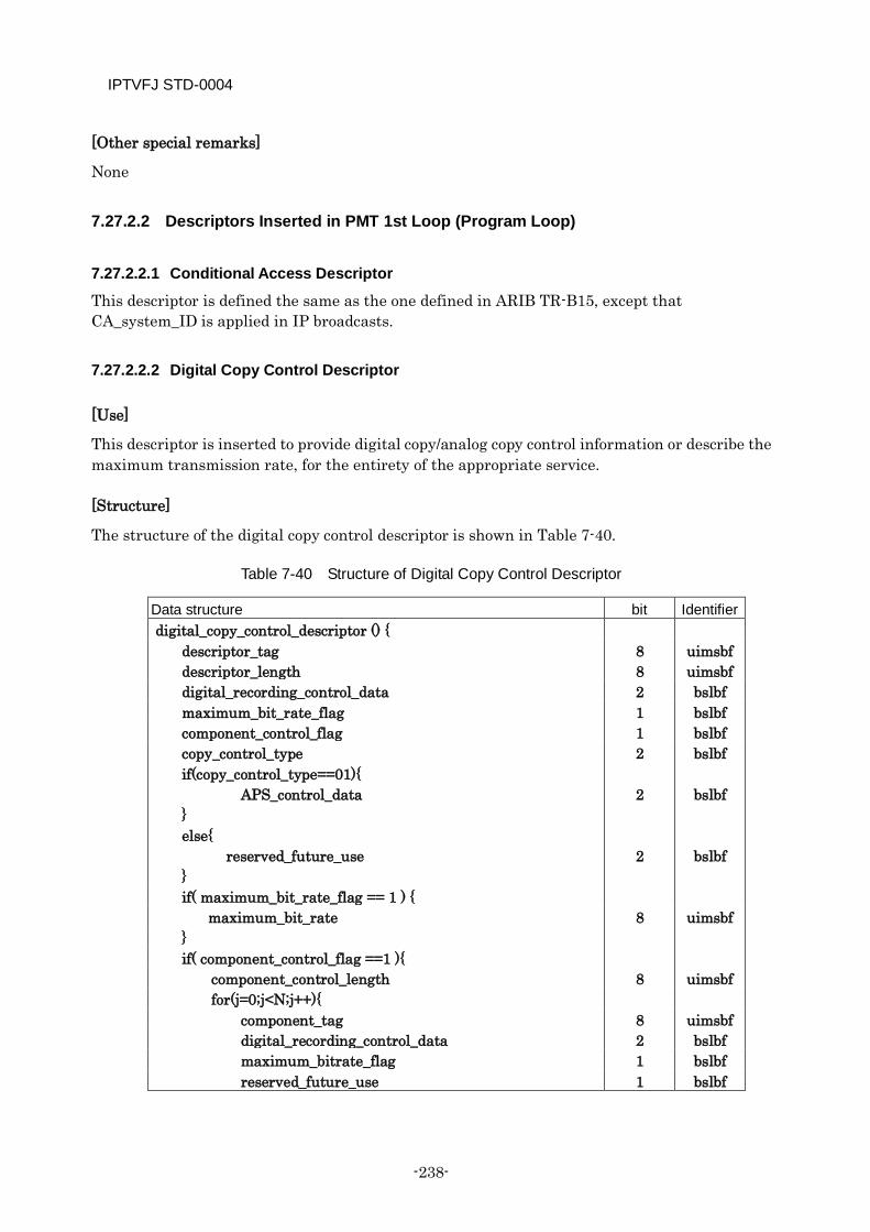
IPTVFJ STD-0004
-238-
[Other special remarks]
None
7.27.2.2 Descriptors Inserted in PMT 1st Loop (Program Loop)
7.27.2.2.1 Conditional Access Descriptor
This descriptor is defined the same as the one defined in ARIB TR-B15, except that CA_system_ID is applied in IP broadcasts.
7.27.2.2.2 Digital Copy Control Descriptor
[Use]
This descriptor is inserted to provide digital copy/analog copy control information or describe the maximum transmission rate, for the entirety of the appropriate service.
[Structure]
The structure of the digital copy control descriptor is shown in Table 7-40.
Table 7-40 Structure of Digital Copy Control Descriptor
Data structure bit Identifier digital_copy_control_descriptor () {
descriptor_tag 8 uimsbf descriptor_length 8 uimsbf digital_recording_control_data 2 bslbf maximum_bit_rate_flag 1 bslbf component_control_flag 1 bslbf copy_control_type if(copy_control_type==01){ APS_control_data } else{ reserved_future_use }
2 2 2
bslbf
bslbf
bslbf
if( maximum_bit_rate_flag == 1 ) { maximum_bit_rate 8 uimsbf
} if( component_control_flag ==1 ){ component_control_length 8 uimsbf for(j=0;j<N;j++){ component_tag 8 uimsbf digital_recording_control_data 2 bslbf maximum_bitrate_flag 1 bslbf reserved_future_use 1 bslbf
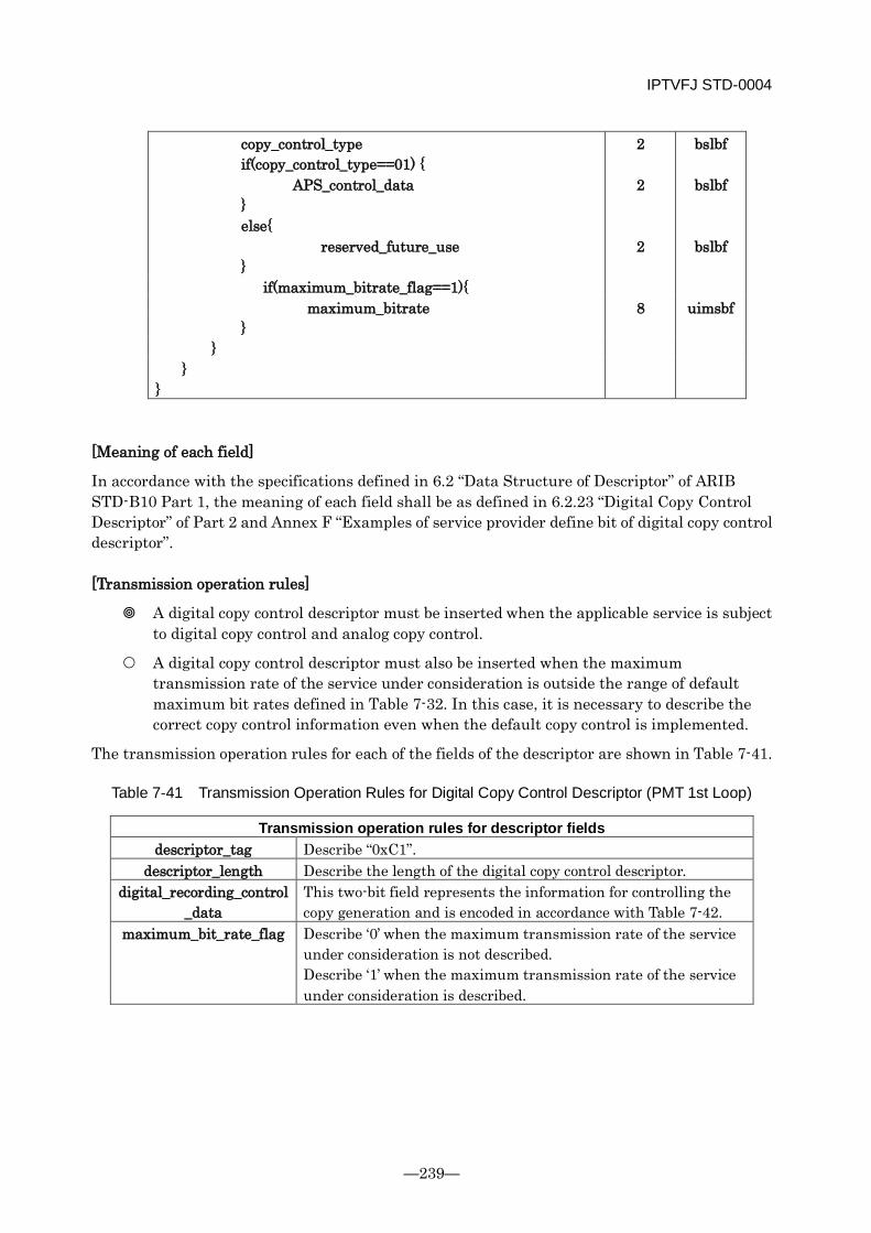
IPTVFJ STD-0004
—239—
copy_control_type if(copy_control_type==01) { APS_control_data } else{
reserved_future_use }
2 2 2
bslbf
bslbf
bslbf
if(maximum_bitrate_flag==1){ maximum_bitrate 8 uimsbf } } }
}
[Meaning of each field]
In accordance with the specifications defined in 6.2 “Data Structure of Descriptor” of ARIB STD-B10 Part 1, the meaning of each field shall be as defined in 6.2.23 “Digital Copy Control Descriptor” of Part 2 and Annex F “Examples of service provider define bit of digital copy control descriptor”.
[Transmission operation rules]
A digital copy control descriptor must be inserted when the applicable service is subject to digital copy control and analog copy control.
A digital copy control descriptor must also be inserted when the maximum transmission rate of the service under consideration is outside the range of default maximum bit rates defined in Table 7-32. In this case, it is necessary to describe the correct copy control information even when the default copy control is implemented.
The transmission operation rules for each of the fields of the descriptor are shown in Table 7-41.
Table 7-41 Transmission Operation Rules for Digital Copy Control Descriptor (PMT 1st Loop)
Transmission operation rules for descriptor fields descriptor_tag Describe “0xC1”.
descriptor_length Describe the length of the digital copy control descriptor. digital_recording_control
_data This two-bit field represents the information for controlling the copy generation and is encoded in accordance with Table 7-42.
maximum_bit_rate_flag Describe ‘0’ when the maximum transmission rate of the service under consideration is not described. Describe ‘1’ when the maximum transmission rate of the service under consideration is described.
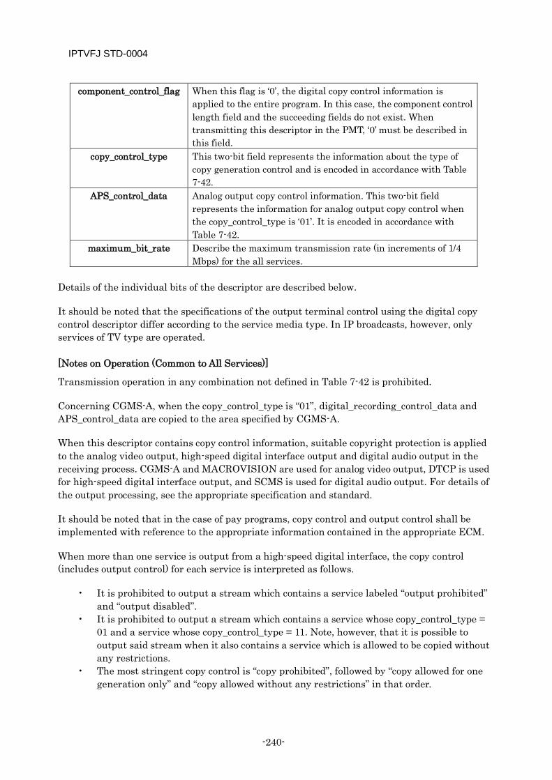
IPTVFJ STD-0004
-240-
component_control_flag When this flag is ‘0’, the digital copy control information is applied to the entire program. In this case, the component control length field and the succeeding fields do not exist. When transmitting this descriptor in the PMT, ‘0’ must be described in this field.
copy_control_type This two-bit field represents the information about the type of copy generation control and is encoded in accordance with Table 7-42.
APS_control_data Analog output copy control information. This two-bit field represents the information for analog output copy control when the copy_control_type is ‘01’. It is encoded in accordance with Table 7-42.
maximum_bit_rate Describe the maximum transmission rate (in increments of 1/4 Mbps) for the all services.
Details of the individual bits of the descriptor are described below.
It should be noted that the specifications of the output terminal control using the digital copy control descriptor differ according to the service media type. In IP broadcasts, however, only services of TV type are operated.
[Notes on Operation (Common to All Services)]
Transmission operation in any combination not defined in Table 7-42 is prohibited.
Concerning CGMS-A, when the copy_control_type is “01”, digital_recording_control_data and APS_control_data are copied to the area specified by CGMS-A.
When this descriptor contains copy control information, suitable copyright protection is applied to the analog video output, high-speed digital interface output and digital audio output in the receiving process. CGMS-A and MACROVISION are used for analog video output, DTCP is used for high-speed digital interface output, and SCMS is used for digital audio output. For details of the output processing, see the appropriate specification and standard.
It should be noted that in the case of pay programs, copy control and output control shall be implemented with reference to the appropriate information contained in the appropriate ECM.
When more than one service is output from a high-speed digital interface, the copy control (includes output control) for each service is interpreted as follows.
• It is prohibited to output a stream which contains a service labeled “output prohibited” and “output disabled”.
• It is prohibited to output a stream which contains a service whose copy_control_type = 01 and a service whose copy_control_type = 11. Note, however, that it is possible to output said stream when it also contains a service which is allowed to be copied without any restrictions.
• The most stringent copy control is “copy prohibited”, followed by “copy allowed for one generation only” and “copy allowed without any restrictions” in that order.

IPTVFJ STD-0004
—241—
It is necessary to properly reflect the copy control information in the copyright indication bit of the channel status specified in IEC 60958 and the category code.
The category code when a digital copy control descriptor has been inserted is 001_0000L.
Copy allowed without any restrictions: Set the copyright information bit to 1.
Copy allowed for one generation only: Set both the copyright information bit and the L bit of category code to 0.
Copy prohibited: Set the copyright information bit to 0 and the L bit of category code to 1.
When a digital copy control descriptor is not described, it is assumed that the service can be copied freely.
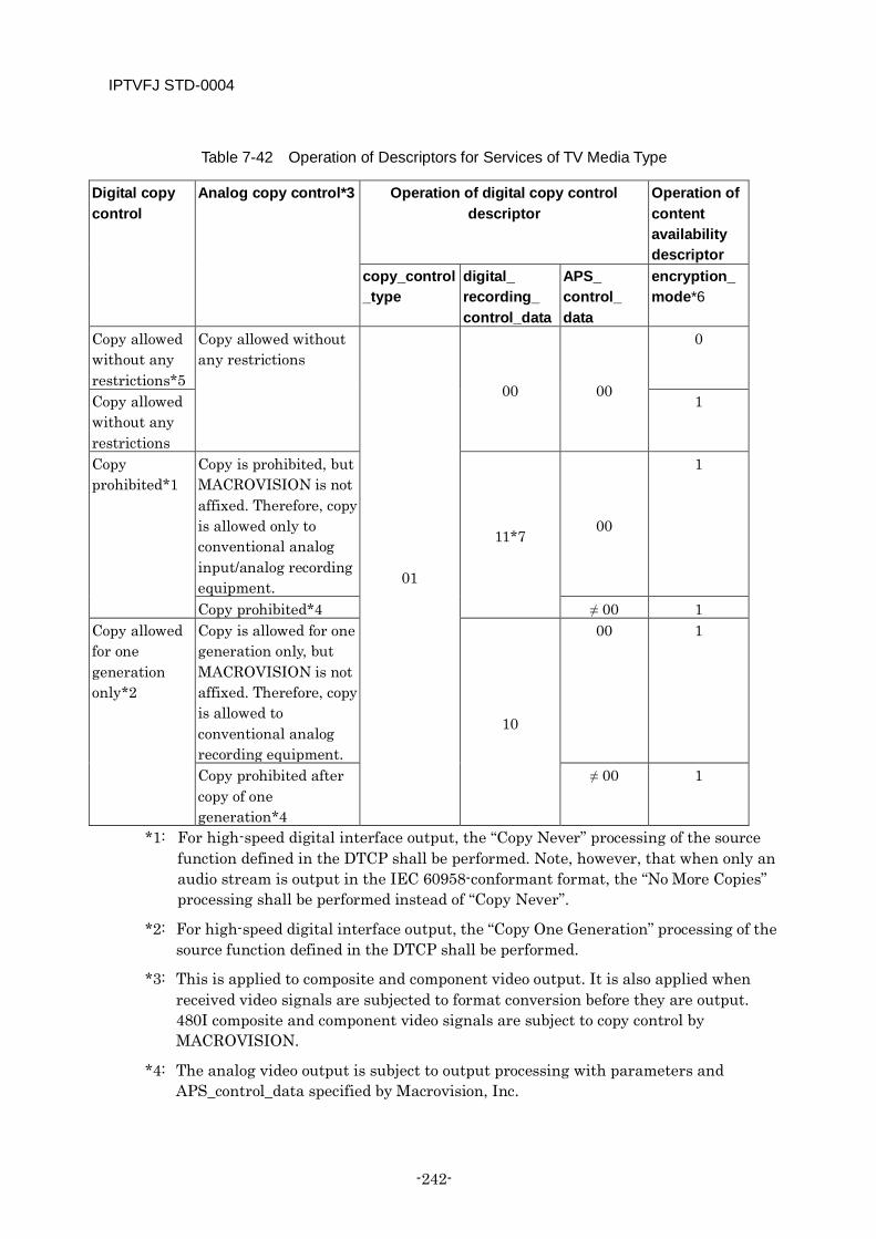
IPTVFJ STD-0004
-242-
Table 7-42 Operation of Descriptors for Services of TV Media Type
Digital copy control
Analog copy control*3 Operation of digital copy control descriptor
Operation of content availability descriptor
copy_control_type
digital_ recording_ control_data
APS_ control_ data
encryption_mode*6
Copy allowed without any restrictions*5
Copy allowed without any restrictions
01
00 00
0
Copy allowed without any restrictions
1
Copy prohibited*1
Copy is prohibited, but MACROVISION is not affixed. Therefore, copy is allowed only to conventional analog input/analog recording equipment.
11*7 00
1
Copy prohibited*4 ≠ 00 1 Copy allowed for one generation only*2
Copy is allowed for one generation only, but MACROVISION is not affixed. Therefore, copy is allowed to conventional analog recording equipment.
10
00 1
Copy prohibited after copy of one generation*4
≠ 00 1
*1: For high-speed digital interface output, the “Copy Never” processing of the source function defined in the DTCP shall be performed. Note, however, that when only an audio stream is output in the IEC 60958-conformant format, the “No More Copies” processing shall be performed instead of “Copy Never”.
*2: For high-speed digital interface output, the “Copy One Generation” processing of the source function defined in the DTCP shall be performed.
*3: This is applied to composite and component video output. It is also applied when received video signals are subjected to format conversion before they are output. 480I composite and component video signals are subject to copy control by MACROVISION.
*4: The analog video output is subject to output processing with parameters and APS_control_data specified by Macrovision, Inc.

IPTVFJ STD-0004
—243—
*5: High-speed digital interface output shall be encrypted in accordance with the DTCP specifications. Note, however, that when only an audio stream is output in the IEC 609568-conformant format, it shall not be encrypted.
*6: In the absence of a content availability descriptor, the encryption_mode is determined to be ‘1’.
*7: In IP broadcasts, Hyper-View is not operated. Therefore, a digital copy control descriptor with digital_recording_control_data ‘11’ is not operated. (For details, see [Appendix B].)
[Notes on Operation (Service of TV Media Type)]
When the service_type described in the service list descriptor of the NIT is “0x01” (digital TV service), “0xA5” (promotion video service) or “0x80” (video service for adults), the service must be encrypted in accordance with Table 7-42.
[Reception processing criteria]
The reception processing criteria for the individual fields are shown in Table 7-43.
Table 7-43 Reception processing criteria for Digital Copy Control Descriptor (PMT 1st Loop)
Reception processing criteria for individual fields descriptor_tag = “0xC1”: The descriptor is determined to be a digital copy control
descriptor. descriptor_length This is determined to be the length of the digital copy control
descriptor. digital_recording_control
_data This two-bit field represents the information for controlling copy generation and is decoded in accordance with Table 7-42.
maximum_bit_rate_flag = ‘0’: The maximum transmission rate of the appropriate service is determined to be within the range of default maximum bit rates defined in Table 7-31 and Table 7-32.
= ‘1’: It is determined that the maximum transmission rate of the appropriate service is described in the subsequent field.
component_control_flag = ‘0’: The descriptor is determined valid. = ‘1’: The descriptor is determined invalid.
copy_control_type This two-bit field represents the information about the type of copy generation control and is decoded in accordance with Table 7-42.
maximum_bit_rate This is determined to be the maximum transmission rate of the appropriate service.
[Other special remarks]
The copy control of analog output signals depends on a separate agreement between the broadcaster concerned and Macrovision, Inc., etc. Therefore, it is considered necessary to discuss it carefully in the future.
The reception processing to be performed in cases not defined in Table 7-42 is shown below.
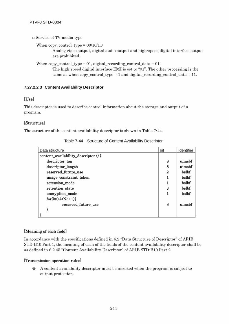
IPTVFJ STD-0004
-244-
□ Service of TV media type
When copy_control_type = 00/10/11: Analog video output, digital audio output and high-speed digital interface output are prohibited.
When copy_control_type = 01, digital_recording_control_data = 01: The high-speed digital interface EMI is set to “01”. The other processing is the same as when copy_control_type = 1 and digital_recording_control_data = 11.
7.27.2.2.3 Content Availability Descriptor
[Use]
This descriptor is used to describe control information about the storage and output of a program.
[Structure]
The structure of the content availability descriptor is shown in Table 7-44.
Table 7-44 Structure of Content Availability Descriptor
Data structure bit Identifier content_availability_descriptor () {
descriptor_tag 8 uimsbf descriptor_length 8 uimsbf reserved_future_use 2 bslbf image_constraint_token 1 bslbf retention_mode 1 bslbf retention_state 3 bslbf encryption_mode 1 bslbf for(i=0;i<N;i++){ reserved_future_use }
8
uimsbf
}
[Meaning of each field]
In accordance with the specifications defined in 6.2 “Data Structure of Descriptor” of ARIB STD-B10 Part 1, the meaning of each of the fields of the content availability descriptor shall be as defined in 6.2.45 “Content Availability Descriptor” of ARIB STD-B10 Part 2.
[Transmission operation rules]
A content availability descriptor must be inserted when the program is subject to output protection.
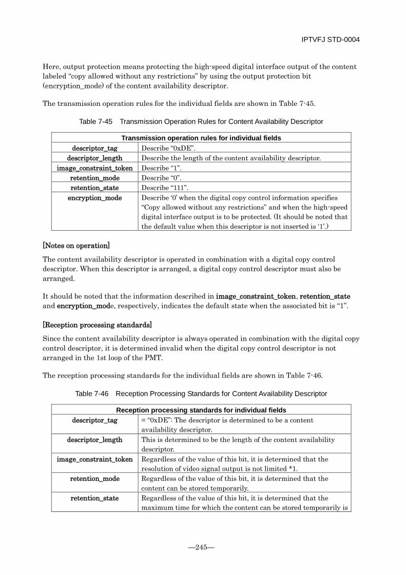
IPTVFJ STD-0004
—245—
Here, output protection means protecting the high-speed digital interface output of the content labeled “copy allowed without any restrictions” by using the output protection bit (encryption_mode) of the content availability descriptor.
The transmission operation rules for the individual fields are shown in Table 7-45.
Table 7-45 Transmission Operation Rules for Content Availability Descriptor
Transmission operation rules for individual fields descriptor_tag Describe “0xDE”.
descriptor_length Describe the length of the content availability descriptor. image_constraint_token Describe “1”.
retention_mode Describe “0”. retention_state Describe “111”.
encryption_mode Describe ‘0’ when the digital copy control information specifies “Copy allowed without any restrictions” and when the high-speed digital interface output is to be protected. (It should be noted that the default value when this descriptor is not inserted is ‘1’.)
[Notes on operation]
The content availability descriptor is operated in combination with a digital copy control descriptor. When this descriptor is arranged, a digital copy control descriptor must also be arranged.
It should be noted that the information described in image_constraint_token, retention_state and encryption_mode, respectively, indicates the default state when the associated bit is “1”.
[Reception processing standards]
Since the content availability descriptor is always operated in combination with the digital copy control descriptor, it is determined invalid when the digital copy control descriptor is not arranged in the 1st loop of the PMT.
The reception processing standards for the individual fields are shown in Table 7-46.
Table 7-46 Reception Processing Standards for Content Availability Descriptor
Reception processing standards for individual fields descriptor_tag = “0xDE”: The descriptor is determined to be a content
availability descriptor. descriptor_length This is determined to be the length of the content availability
descriptor. image_constraint_token Regardless of the value of this bit, it is determined that the
resolution of video signal output is not limited *1. retention_mode Regardless of the value of this bit, it is determined that the
content can be stored temporarily. retention_state Regardless of the value of this bit, it is determined that the
maximum time for which the content can be stored temporarily is
IPTVFJ STD-0004
-246-
one hour and 30 minutes *1. encryption_mode = ‘1’: It is determined that the high-speed digital interface output
is not protected *2. = ‘0’: It is determined that the high-speed digital interface output
is protected *2. *1: The bit makes sense only when the digital copy control information specifies “Copy
prohibited”. (For details, see [Appendix B].) *2: The bit makes sense only when the digital copy control information specifies “Copy allowed
without any restrictions”. (For details, see [Appendix B].)
[Other special remarks]
When this descriptor is not arranged, it is determined that the following fields have the following values.
• image_constraint_token=‘1’ • retention_mode=’0’ • retention_state=’111’ • encryption_mode=’1’
For details about the operation and processing, see 7.19 and [Appendix B].
The high-speed digital interface shall be controlled in accordance with the specifications defined in the DTCP.
7.27.2.3 Descriptors Inserted in PMT 2nd Loop (ES Loop)
7.27.2.3.1 Stream Identifier Descriptor
See ARIB TR-B15.
7.27.2.3.2 Data Component Descriptor
For the transmission operation of this descriptor, see ARIB TR-B15. It should be noted, however, that in IP broadcasts, only the components for transmitting captions are operated: the components for transmitting character superimpositions and data carousels are not operated.
7.27.2.3.3 Video Decode Control Descriptor
See ARIB TR-B15. It should be noted, however, that in IP broadcasts, still pictures are not operated.
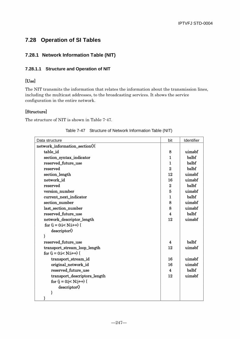
IPTVFJ STD-0004
—247—
7.28 Operation of SI Tables
7.28.1 Network Information Table (NIT)
7.28.1.1 Structure and Operation of NIT
[Use]
The NIT transmits the information that relates the information about the transmission lines, including the multicast addresses, to the broadcasting services. It shows the service configuration in the entire network.
[Structure]
The structure of NIT is shown in Table 7-47.
Table 7-47 Structure of Network Information Table (NIT)
Data structure bit Identifier network_information_section(){
table_id 8 uimsbf section_syntax_indicator 1 bslbf reserved_future_use 1 bslbf reserved 2 bslbf section_length 12 uimsbf network_id 16 uimsbf reserved 2 bslbf version_number 5 uimsbf current_next_indicator 1 bslbf section_number 8 uimsbf last_section_number 8 uimsbf reserved_future_use 4 bslbf network_descriptor_length 12 uimsbf for (i = 0;i< N;i++) {
descriptor() } reserved_future_use 4 bslbf transport_stream_loop_length 12 uimsbf for (i = 0;i< N;i++) {
transport_stream_id 16 uimsbf original_network_id 16 uimsbf reserved_future_use 4 bslbf transport_descriptors_length 12 uimsbf for (j = 0;j< N;j++) {
descriptor() }
}
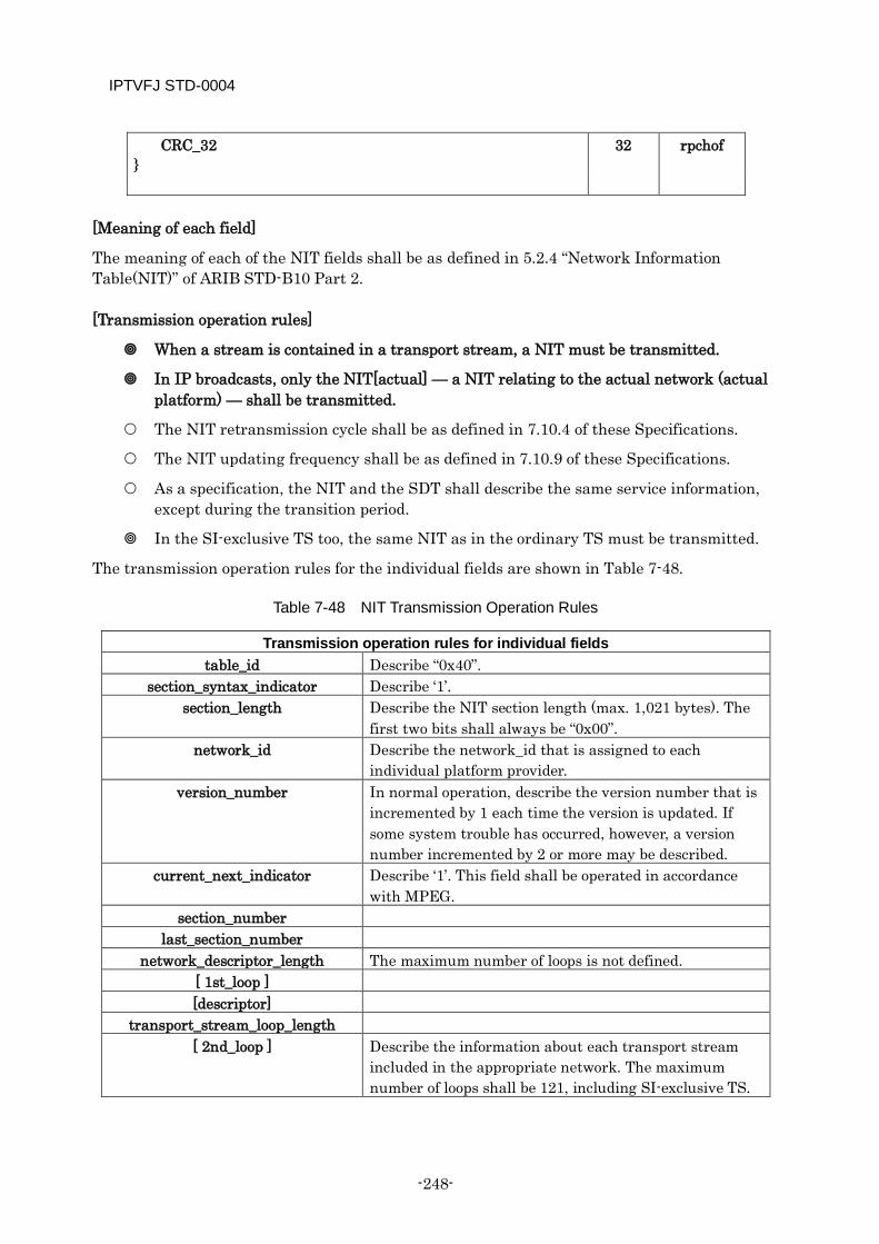
IPTVFJ STD-0004
-248-
CRC_32 32 rpchof }
[Meaning of each field]
The meaning of each of the NIT fields shall be as defined in 5.2.4 “Network Information Table(NIT)” of ARIB STD-B10 Part 2.
[Transmission operation rules]
When a stream is contained in a transport stream, a NIT must be transmitted.
In IP broadcasts, only the NIT[actual] — a NIT relating to the actual network (actual platform) — shall be transmitted.
The NIT retransmission cycle shall be as defined in 7.10.4 of these Specifications.
The NIT updating frequency shall be as defined in 7.10.9 of these Specifications.
As a specification, the NIT and the SDT shall describe the same service information, except during the transition period.
In the SI-exclusive TS too, the same NIT as in the ordinary TS must be transmitted.
The transmission operation rules for the individual fields are shown in Table 7-48.
Table 7-48 NIT Transmission Operation Rules
Transmission operation rules for individual fields table_id Describe “0x40”.
section_syntax_indicator Describe ‘1’. section_length Describe the NIT section length (max. 1,021 bytes). The
first two bits shall always be “0x00”. network_id Describe the network_id that is assigned to each
individual platform provider. version_number In normal operation, describe the version number that is
incremented by 1 each time the version is updated. If some system trouble has occurred, however, a version number incremented by 2 or more may be described.
current_next_indicator Describe ‘1’. This field shall be operated in accordance with MPEG.
section_number last_section_number
network_descriptor_length The maximum number of loops is not defined. [ 1st_loop ] [descriptor]
transport_stream_loop_length [ 2nd_loop ] Describe the information about each transport stream
included in the appropriate network. The maximum number of loops shall be 121, including SI-exclusive TS.
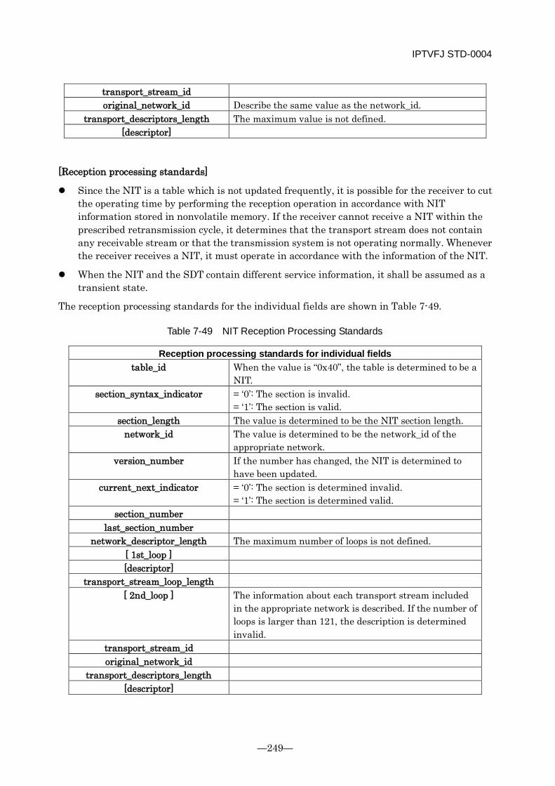
IPTVFJ STD-0004
—249—
transport_stream_id original_network_id Describe the same value as the network_id.
transport_descriptors_length The maximum value is not defined. [descriptor]
[Reception processing standards]
Since the NIT is a table which is not updated frequently, it is possible for the receiver to cut the operating time by performing the reception operation in accordance with NIT information stored in nonvolatile memory. If the receiver cannot receive a NIT within the prescribed retransmission cycle, it determines that the transport stream does not contain any receivable stream or that the transmission system is not operating normally. Whenever the receiver receives a NIT, it must operate in accordance with the information of the NIT.
When the NIT and the SDT contain different service information, it shall be assumed as a transient state.
The reception processing standards for the individual fields are shown in Table 7-49.
Table 7-49 NIT Reception Processing Standards
Reception processing standards for individual fields table_id When the value is “0x40”, the table is determined to be a
NIT. section_syntax_indicator = ‘0’: The section is invalid.
= ‘1’: The section is valid. section_length The value is determined to be the NIT section length.
network_id The value is determined to be the network_id of the appropriate network.
version_number If the number has changed, the NIT is determined to have been updated.
current_next_indicator = ‘0’: The section is determined invalid. = ‘1’: The section is determined valid.
section_number last_section_number
network_descriptor_length The maximum number of loops is not defined. [ 1st_loop ] [descriptor]
transport_stream_loop_length [ 2nd_loop ] The information about each transport stream included
in the appropriate network is described. If the number of loops is larger than 121, the description is determined invalid.
transport_stream_id original_network_id
transport_descriptors_length [descriptor]
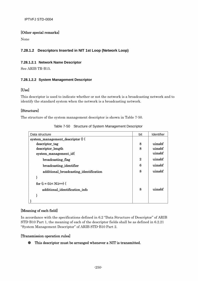
IPTVFJ STD-0004
-250-
[Other special remarks]
None
7.28.1.2 Descriptors Inserted in NIT 1st Loop (Network Loop)
7.28.1.2.1 Network Name Descriptor
See ARIB TR-B15.
7.28.1.2.2 System Management Descriptor
[Use]
This descriptor is used to indicate whether or not the network is a broadcasting network and to identify the standard system when the network is a broadcasting network.
[Structure]
The structure of the system management descriptor is shown in Table 7-50.
Table 7-50 Structure of System Management Descriptor
Data structure bit Identifier system_management_descriptor () {
descriptor_tag 8 uimsbf descriptor_length 8 uimsbf system_management_id{ uimsbf
broadcasting_flag 2 uimsbf
broadcasting_identifier 6 uimsbf
additional_broadcasting_identification 8 uimsbf
}
for (i = 0;i< N;i++) {
additional_identification_info 8 uimsbf
} }
[Meaning of each field]
In accordance with the specifications defined in 6.2 “Data Structure of Descriptor” of ARIB STD-B10 Part 1, the meaning of each of the descriptor fields shall be as defined in 6.2.21 “System Management Descriptor” of ARIB STD-B10 Part 2.
[Transmission operation rules]
This descriptor must be arranged whenever a NIT is transmitted.
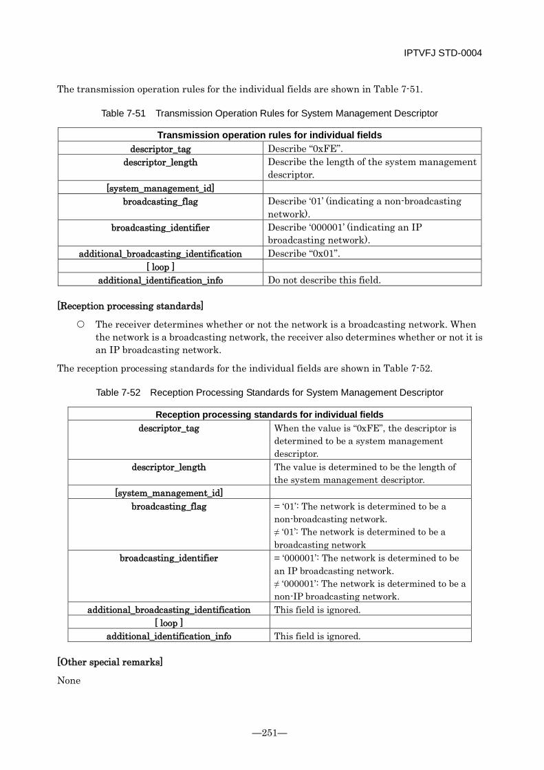
IPTVFJ STD-0004
—251—
The transmission operation rules for the individual fields are shown in Table 7-51.
Table 7-51 Transmission Operation Rules for System Management Descriptor
Transmission operation rules for individual fields descriptor_tag Describe “0xFE”.
descriptor_length Describe the length of the system management descriptor.
[system_management_id] broadcasting_flag Describe ‘01’ (indicating a non-broadcasting
network). broadcasting_identifier Describe ‘000001’ (indicating an IP
broadcasting network). additional_broadcasting_identification Describe “0x01”.
[ loop ] additional_identification_info Do not describe this field.
[Reception processing standards]
The receiver determines whether or not the network is a broadcasting network. When the network is a broadcasting network, the receiver also determines whether or not it is an IP broadcasting network.
The reception processing standards for the individual fields are shown in Table 7-52.
Table 7-52 Reception Processing Standards for System Management Descriptor
Reception processing standards for individual fields descriptor_tag When the value is “0xFE”, the descriptor is
determined to be a system management descriptor.
descriptor_length The value is determined to be the length of the system management descriptor.
[system_management_id] broadcasting_flag = ‘01’: The network is determined to be a
non-broadcasting network. ≠ ‘01’: The network is determined to be a broadcasting network
broadcasting_identifier = ‘000001’: The network is determined to be an IP broadcasting network. ≠ ‘000001’: The network is determined to be a non-IP broadcasting network.
additional_broadcasting_identification This field is ignored. [ loop ]
additional_identification_info This field is ignored.
[Other special remarks]
None
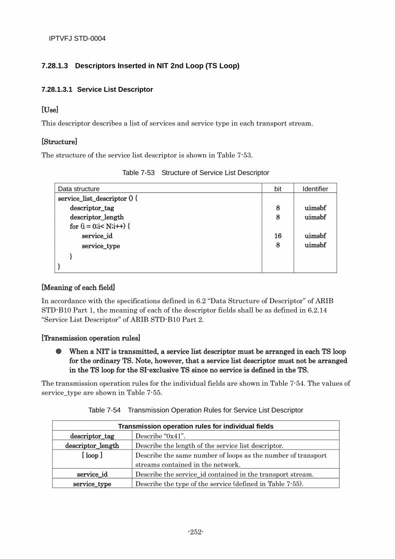
IPTVFJ STD-0004
-252-
7.28.1.3 Descriptors Inserted in NIT 2nd Loop (TS Loop)
7.28.1.3.1 Service List Descriptor
[Use]
This descriptor describes a list of services and service type in each transport stream.
[Structure]
The structure of the service list descriptor is shown in Table 7-53.
Table 7-53 Structure of Service List Descriptor
Data structure bit Identifier service_list_descriptor () {
descriptor_tag 8 uimsbf descriptor_length 8 uimsbf for (i = 0;i< N;i++) {
service_id 16 uimsbf service_type 8 uimsbf
} }
[Meaning of each field]
In accordance with the specifications defined in 6.2 “Data Structure of Descriptor” of ARIB STD-B10 Part 1, the meaning of each of the descriptor fields shall be as defined in 6.2.14 “Service List Descriptor” of ARIB STD-B10 Part 2.
[Transmission operation rules]
When a NIT is transmitted, a service list descriptor must be arranged in each TS loop for the ordinary TS. Note, however, that a service list descriptor must not be arranged in the TS loop for the SI-exclusive TS since no service is defined in the TS.
The transmission operation rules for the individual fields are shown in Table 7-54. The values of service_type are shown in Table 7-55.
Table 7-54 Transmission Operation Rules for Service List Descriptor
Transmission operation rules for individual fields descriptor_tag Describe “0x41”.
descriptor_length Describe the length of the service list descriptor. [ loop ] Describe the same number of loops as the number of transport
streams contained in the network. service_id Describe the service_id contained in the transport stream.
service_type Describe the type of the service (defined in Table 7-55).
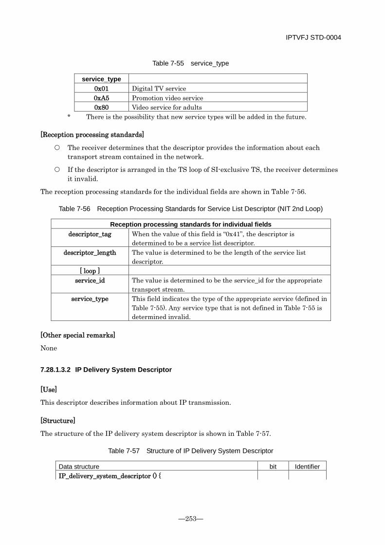
IPTVFJ STD-0004
—253—
Table 7-55 service_type
service_type 0x01 Digital TV service 0xA5 Promotion video service 0x80 Video service for adults
* There is the possibility that new service types will be added in the future.
[Reception processing standards]
The receiver determines that the descriptor provides the information about each transport stream contained in the network.
If the descriptor is arranged in the TS loop of SI-exclusive TS, the receiver determines it invalid.
The reception processing standards for the individual fields are shown in Table 7-56.
Table 7-56 Reception Processing Standards for Service List Descriptor (NIT 2nd Loop)
Reception processing standards for individual fields descriptor_tag When the value of this field is “0x41”, the descriptor is
determined to be a service list descriptor. descriptor_length The value is determined to be the length of the service list
descriptor. [ loop ]
service_id The value is determined to be the service_id for the appropriate transport stream.
service_type This field indicates the type of the appropriate service (defined in Table 7-55). Any service type that is not defined in Table 7-55 is determined invalid.
[Other special remarks]
None
7.28.1.3.2 IP Delivery System Descriptor
[Use]
This descriptor describes information about IP transmission.
[Structure]
The structure of the IP delivery system descriptor is shown in Table 7-57.
Table 7-57 Structure of IP Delivery System Descriptor
Data structure bit Identifier IP_delivery_system_descriptor () {
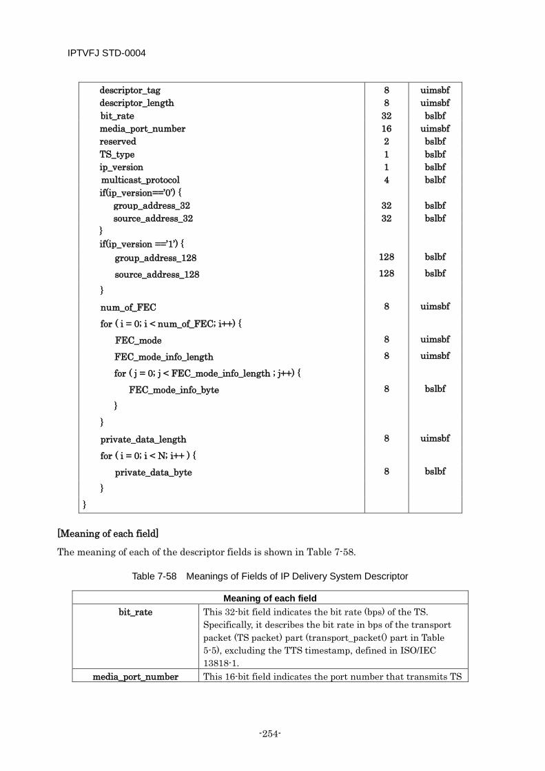
IPTVFJ STD-0004
-254-
descriptor_tag 8 uimsbf descriptor_length 8 uimsbf bit_rate 32 bslbf media_port_number 16 uimsbf reserved 2 bslbf TS_type 1 bslbf ip_version 1 bslbf multicast_protocol 4 bslbf if(ip_version==’0’) { group_address_32 32 bslbf source_address_32 32 bslbf } if(ip_version ==’1’) {
group_address_128 128 bslbf
source_address_128 128 bslbf
}
num_of_FEC 8 uimsbf
for ( i = 0; i < num_of_FEC; i++) {
FEC_mode 8 uimsbf
FEC_mode_info_length 8 uimsbf
for ( j = 0; j < FEC_mode_info_length ; j++) {
FEC_mode_info_byte 8 bslbf
}
}
private_data_length 8 uimsbf
for ( i = 0; i < N; i++ ) {
private_data_byte 8 bslbf
}
}
[Meaning of each field]
The meaning of each of the descriptor fields is shown in Table 7-58.
Table 7-58 Meanings of Fields of IP Delivery System Descriptor
Meaning of each field bit_rate This 32-bit field indicates the bit rate (bps) of the TS.
Specifically, it describes the bit rate in bps of the transport packet (TS packet) part (transport_packet() part in Table 5-5), excluding the TTS timestamp, defined in ISO/IEC 13818-1.
media_port_number This 16-bit field indicates the port number that transmits TS

IPTVFJ STD-0004
—255—
data. TS_type This 1-bit flag indicates the TS format type.
“0”: Ordinary TS “1”: SI-exclusive TS
ip_version This 1-bit flag indicates the version of IP transmission protocol. “0”: IPv4 transmission protocol “1”: IPv6 transmission protocol
multicast_protocol This 4-bit field indicates the multicast control protocol. At the start of IP broadcasting, either of the following values is defined. = 0x0: IGMPv2 control protocol = 0x1: MLDv2 control protocol
group_address_32 This 32-bit field indicates a multicast group address in IPv4. source_address_32 This 32-bit field indicates a multicast source address in IPv4. group_address_128 This 128-bit field indicates a multicast group address in IPv6. source_address_128 This 128-bit field indicates a multicast source address in
IPv6. num_of_FEC This field indicates the FEC system number that is applied. FEC_mode This 8-bit field indicates the FEC system. For the
relationship between the value of this field and the FEC system/parameter, see Table 7-59.
FEC_mode_info_length This 8-bit field indicates the length in bytes of the succeeding additional information about the FEC system.
[FEC_mode_info_byte] This 8-bit field indicates the additional information about the FEC system. For the structure and meaning of this field in each FEC_mode, see Table 7-60 and Table 7-61.
private_data_length This 8-bit field indicates the length in bytes of the succeeding private_data_byte.
[private_data_byte] This 8-bit field is used for descriptor extension in the future.
Table 7-59 FEC_modes That Can Be Specified in IP Broadcasts
FEC_mode FEC system Parameter 0x00(*1) FEC not applied.
0x01 Pro-MPEC 1D source IP address: Same as in media packet. FEC port number (vertical direction): media_port_number + 2
0x02 Pro-MPEG 2D source IP address: Same as in media packet. FEC port number (vertical direction): media_port_number + 2 FEC port number (horizontal direction): media_port_number + 4
0x03~0xFF Undefined *1 When FEC is not applied, the descriptor shall be transmitted with num_of_FEC, not
FEC_mode, set to 0.
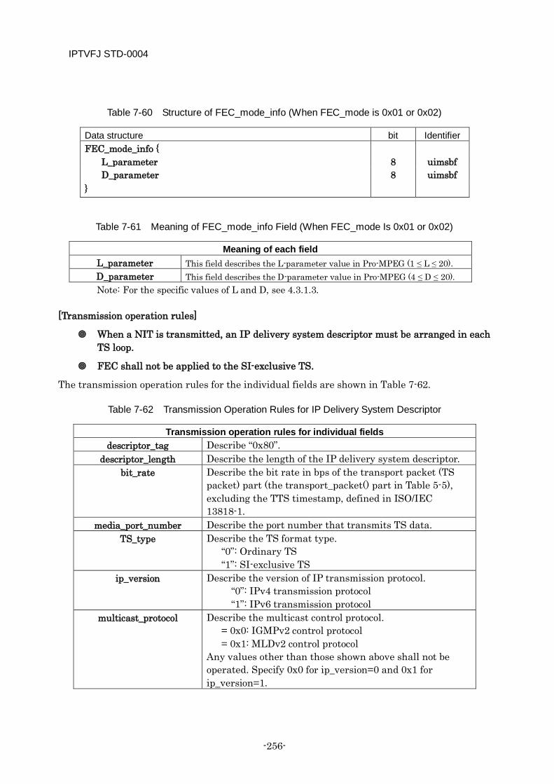
IPTVFJ STD-0004
-256-
Table 7-60 Structure of FEC_mode_info (When FEC_mode is 0x01 or 0x02)
Data structure bit Identifier FEC_mode_info {
L_parameter 8 uimsbf D_parameter 8 uimsbf
}
Table 7-61 Meaning of FEC_mode_info Field (When FEC_mode Is 0x01 or 0x02)
Meaning of each field L_parameter This field describes the L-parameter value in Pro-MPEG (1 ≤ L ≤ 20). D_parameter This field describes the D-parameter value in Pro-MPEG (4 ≤ D ≤ 20). Note: For the specific values of L and D, see 4.3.1.3.
[Transmission operation rules]
When a NIT is transmitted, an IP delivery system descriptor must be arranged in each TS loop.
FEC shall not be applied to the SI-exclusive TS.
The transmission operation rules for the individual fields are shown in Table 7-62.
Table 7-62 Transmission Operation Rules for IP Delivery System Descriptor
Transmission operation rules for individual fields descriptor_tag Describe “0x80”.
descriptor_length Describe the length of the IP delivery system descriptor. bit_rate Describe the bit rate in bps of the transport packet (TS
packet) part (the transport_packet() part in Table 5-5), excluding the TTS timestamp, defined in ISO/IEC 13818-1.
media_port_number Describe the port number that transmits TS data. TS_type Describe the TS format type.
“0”: Ordinary TS “1”: SI-exclusive TS
ip_version Describe the version of IP transmission protocol. “0”: IPv4 transmission protocol “1”: IPv6 transmission protocol
multicast_protocol Describe the multicast control protocol. = 0x0: IGMPv2 control protocol = 0x1: MLDv2 control protocol Any values other than those shown above shall not be operated. Specify 0x0 for ip_version=0 and 0x1 for ip_version=1.
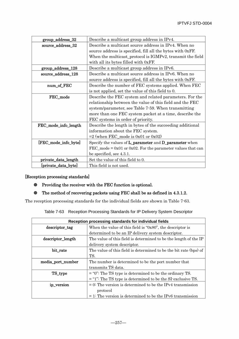
IPTVFJ STD-0004
—257—
group_address_32 Describe a multicast group address in IPv4. source_address_32 Describe a multicast source address in IPv4. When no
source address is specified, fill all the bytes with 0xFF. When the multicast_protocol is IGMPv2, transmit the field with all its bytes filled with 0xFF.
group_address_128 Describe a multicast group address in IPv6. source_address_128 Describe a multicast source address in IPv6. When no
source address is specified, fill all the bytes with 0xFF. num_of_FEC Describe the number of FEC systems applied. When FEC
is not applied, set the value of this field to 0. FEC_mode Describe the FEC system and related parameters. For the
relationship between the value of this field and the FEC system/parameter, see Table 7-59. When transmitting more than one FEC system packet at a time, describe the FEC systems in order of priority.
FEC_mode_info_length Describe the length in bytes of the succeeding additional information about the FEC system. =2 (when FEC_mode is 0x01 or 0x02)
[FEC_mode_info_byte] Specify the values of L_parameter and D_parameter when FEC_mode = 0x01 or 0x02. For the parameter values that can be specified, see 4.3.1.
private_data_length Set the value of this field to 0. [private_data_byte] This field is not used.
[Reception processing standards]
Providing the receiver with the FEC function is optional.
The method of recovering packets using FEC shall be as defined in 4.3.1.2.
The reception processing standards for the individual fields are shown in Table 7-63.
Table 7-63 Reception Processing Standards for IP Delivery System Descriptor
Reception processing standards for individual fields descriptor_tag When the value of this field is “0x80”, the descriptor is
determined to be an IP delivery system descriptor. descriptor_length The value of this field is determined to be the length of the IP
delivery system descriptor. bit_rate The value of this field is determined to be the bit rate (bps) of
TS. media_port_number The number is determined to be the port number that
transmits TS data. TS_type = “0”: The TS type is determined to be the ordinary TS.
= “1”: The TS type is determined to be the SI-exclusive TS. ip_version = 0: The version is determined to be the IPv4 transmission
protocol = 1: The version is determined to be the IPv6 transmission
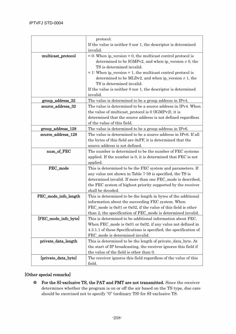
IPTVFJ STD-0004
-258-
protocol. If the value is neither 0 nor 1, the descriptor is determined invalid.
multicast_protocol = 0: When ip_version = 0, the multicast control protocol is determined to be IGMPv2, and when ip_version ≠ 0, the TS is determined invalid.
= 1: When ip_version = 1, the multicast control protocol is determined to be MLDv2, and when ip_version ≠ 1, the TS is determined invalid.
If the value is neither 0 nor 1, the descriptor is determined invalid.
group_address_32 The value is determined to be a group address in IPv4. source_address_32 The value is determined to be a source address in IPv4. When
the value of multicast_protocol is 0 (IGMPv2), it is determined that the source address is not defined regardless of the value of this field.
group_address_128 The value is determined to be a group address in IPv6. source_address_128 The value is determined to be a source address in IPv6. If all
the bytes of this field are 0xFF, it is determined that the source address is not defined.
num_of_FEC The number is determined to be the number of FEC systems applied. If the number is 0, it is determined that FEC is not applied.
FEC_mode This is determined to be the FEC system and parameters. If any value not shown in Table 7-59 is specified, the TS is determined invalid. If more than one FEC_mode is described, the FEC system of highest priority supported by the receiver shall be decoded.
FEC_mode_info_length This is determined to be the length in bytes of the additional information about the succeeding FEC system. When FEC_mode is 0x01 or 0x02, if the value of this field is other than 2, the specification of FEC_mode is determined invalid.
[FEC_mode_info_byte] This is determined to be additional information about FEC. When FEC_mode is 0x01 or 0x02, if any value not defined in 4.3.1.1 of these Specifications is specified, the specification of FEC_mode is determined invalid.
private_data_length This is determined to be the length of private_data_byte. At the start of IP broadcasting, the receiver ignores this field if the value of the field is other than 0.
[private_data_byte] The receiver ignores this field regardless of the value of this field.
[Other special remarks]
For the SI-exclusive TS, the PAT and PMT are not transmitted. Since the receiver determines whether the program is on or off the air based on the TS type, due care should be exercised not to specify “0” (ordinary TS) for SI-exclusive TS.
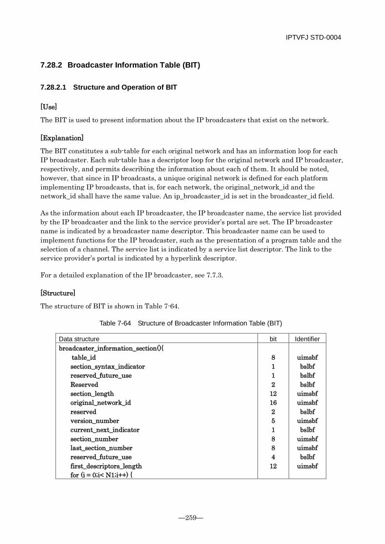
IPTVFJ STD-0004
—259—
7.28.2 Broadcaster Information Table (BIT)
7.28.2.1 Structure and Operation of BIT
[Use]
The BIT is used to present information about the IP broadcasters that exist on the network.
[Explanation]
The BIT constitutes a sub-table for each original network and has an information loop for each IP broadcaster. Each sub-table has a descriptor loop for the original network and IP broadcaster, respectively, and permits describing the information about each of them. It should be noted, however, that since in IP broadcasts, a unique original network is defined for each platform implementing IP broadcasts, that is, for each network, the original_network_id and the network_id shall have the same value. An ip_broadcaster_id is set in the broadcaster_id field.
As the information about each IP broadcaster, the IP broadcaster name, the service list provided by the IP broadcaster and the link to the service provider’s portal are set. The IP broadcaster name is indicated by a broadcaster name descriptor. This broadcaster name can be used to implement functions for the IP broadcaster, such as the presentation of a program table and the selection of a channel. The service list is indicated by a service list descriptor. The link to the service provider’s portal is indicated by a hyperlink descriptor.
For a detailed explanation of the IP broadcaster, see 7.7.3.
[Structure]
The structure of BIT is shown in Table 7-64.
Table 7-64 Structure of Broadcaster Information Table (BIT)
Data structure bit Identifier broadcaster_information_section(){
table_id 8 uimsbf section_syntax_indicator 1 bslbf reserved_future_use 1 bslbf Reserved 2 bslbf section_length 12 uimsbf original_network_id 16 uimsbf reserved 2 bslbf version_number 5 uimsbf current_next_indicator 1 bslbf section_number 8 uimsbf last_section_number 8 uimsbf reserved_future_use 4 bslbf first_descriptors_length 12 uimsbf for (i = 0;i< N1;i++) {
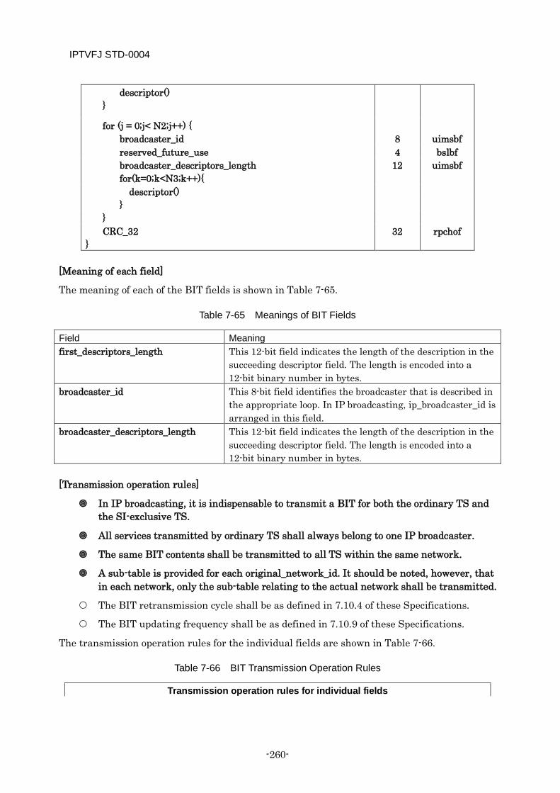
IPTVFJ STD-0004
-260-
descriptor() }
for (j = 0;j< N2;j++) { broadcaster_id 8 uimsbf reserved_future_use 4 bslbf broadcaster_descriptors_length 12 uimsbf for(k=0;k<N3;k++){
descriptor() }
} CRC_32 32 rpchof
}
[Meaning of each field]
The meaning of each of the BIT fields is shown in Table 7-65.
Table 7-65 Meanings of BIT Fields
Field Meaning first_descriptors_length This 12-bit field indicates the length of the description in the
succeeding descriptor field. The length is encoded into a 12-bit binary number in bytes.
broadcaster_id This 8-bit field identifies the broadcaster that is described in the appropriate loop. In IP broadcasting, ip_broadcaster_id is arranged in this field.
broadcaster_descriptors_length This 12-bit field indicates the length of the description in the succeeding descriptor field. The length is encoded into a 12-bit binary number in bytes.
[Transmission operation rules]
In IP broadcasting, it is indispensable to transmit a BIT for both the ordinary TS and the SI-exclusive TS.
All services transmitted by ordinary TS shall always belong to one IP broadcaster.
The same BIT contents shall be transmitted to all TS within the same network.
A sub-table is provided for each original_network_id. It should be noted, however, that in each network, only the sub-table relating to the actual network shall be transmitted.
The BIT retransmission cycle shall be as defined in 7.10.4 of these Specifications.
The BIT updating frequency shall be as defined in 7.10.9 of these Specifications.
The transmission operation rules for the individual fields are shown in Table 7-66.
Table 7-66 BIT Transmission Operation Rules
Transmission operation rules for individual fields
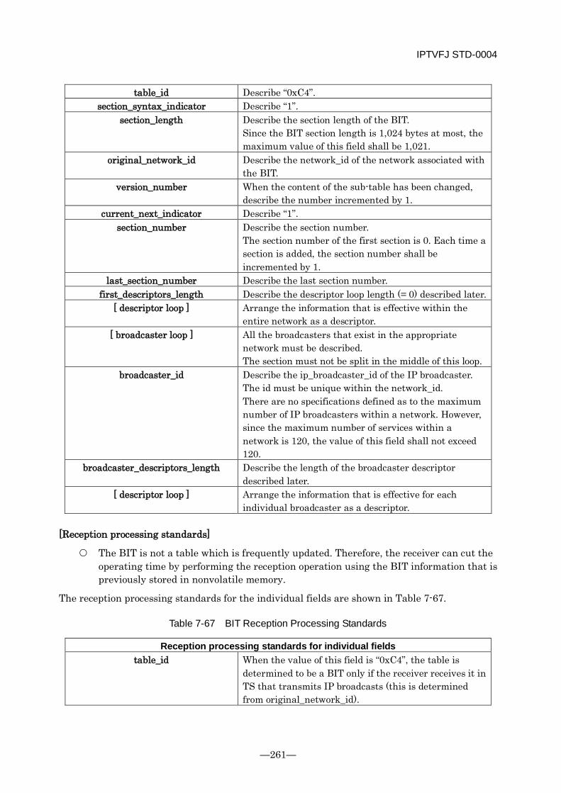
IPTVFJ STD-0004
—261—
table_id Describe “0xC4”. section_syntax_indicator Describe “1”.
section_length Describe the section length of the BIT. Since the BIT section length is 1,024 bytes at most, the maximum value of this field shall be 1,021.
original_network_id Describe the network_id of the network associated with the BIT.
version_number When the content of the sub-table has been changed, describe the number incremented by 1.
current_next_indicator Describe “1”. section_number Describe the section number.
The section number of the first section is 0. Each time a section is added, the section number shall be incremented by 1.
last_section_number Describe the last section number. first_descriptors_length Describe the descriptor loop length (= 0) described later.
[ descriptor loop ] Arrange the information that is effective within the entire network as a descriptor.
[ broadcaster loop ] All the broadcasters that exist in the appropriate network must be described. The section must not be split in the middle of this loop.
broadcaster_id Describe the ip_broadcaster_id of the IP broadcaster. The id must be unique within the network_id. There are no specifications defined as to the maximum number of IP broadcasters within a network. However, since the maximum number of services within a network is 120, the value of this field shall not exceed 120.
broadcaster_descriptors_length Describe the length of the broadcaster descriptor described later.
[ descriptor loop ] Arrange the information that is effective for each individual broadcaster as a descriptor.
[Reception processing standards]
The BIT is not a table which is frequently updated. Therefore, the receiver can cut the operating time by performing the reception operation using the BIT information that is previously stored in nonvolatile memory.
The reception processing standards for the individual fields are shown in Table 7-67.
Table 7-67 BIT Reception Processing Standards
Reception processing standards for individual fields table_id When the value of this field is “0xC4”, the table is
determined to be a BIT only if the receiver receives it in TS that transmits IP broadcasts (this is determined from original_network_id).

IPTVFJ STD-0004
-262-
section_syntax_indicator = “0”: The section is invalid. = “1”: The section is valid.
section_length ≤ 1,021: The length of the section > 1,021: The section is invalid.
original_network_id When the value of this field is the same as the network_id of the actual network, the BIT is determined to be one for the actual network. If a network_id other than that of the actual network is described, the receiver ignores the section.
version_number When the number has changed, it indicates that the sub-table has been updated.
current_next_indicator = “0”: The section is invalid. = “1”: The section is valid.
section_number ≤ last_section_number: The number indicates a section number within the sub-table. > last_section_number: The section is invalid.
last_section_number The number indicates the last section number within the sub-table.
first_descriptors_length This field indicates the following descriptor’s loop length. If the value of this field is determined abnormal from the section_length value, the section itself is assumed to be invalid. If the value of this field is 0, there are no descriptors in the descriptor loop. In this case, the value becomes 0 in all sections regardless of the section number. If the value of this field is other than 0, the receiver jumps over the descriptor length indicated by this field (that is, skips the content of the following descriptor loop) and continues the processing.
[ descriptor loop ] In this loop, descriptors which are effective for the entire network are arranged consecutively. The receiver must be able to process only those descriptors which are declared to be arranged in this field and skip the other descriptors.
[ broadcaster loop ] The loop length of this loop is determined from the values of section_length and first_descriptors_length for each section. The broadcasters that exist in this loop when the receiver receives the entire sub-table are all the broadcasters that exist in the network.
broadcaster_id This field indicates the IP broadcaster that is described in the broadcaster loop.
broadcaster_descriptors_length This field indicates the following descriptor loop length. When the value of this field is 0, it indicates that no descriptors exist in the descriptor loop. If the value of this field is determined abnormal from the section_length value, the section itself is assumed to be invalid.
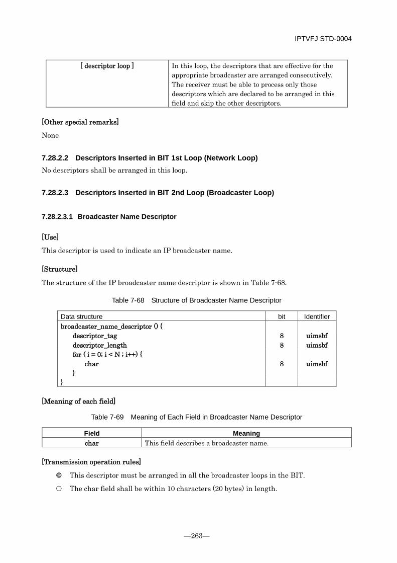
IPTVFJ STD-0004
—263—
[ descriptor loop ] In this loop, the descriptors that are effective for the appropriate broadcaster are arranged consecutively. The receiver must be able to process only those descriptors which are declared to be arranged in this field and skip the other descriptors.
[Other special remarks]
None
7.28.2.2 Descriptors Inserted in BIT 1st Loop (Network Loop) No descriptors shall be arranged in this loop.
7.28.2.3 Descriptors Inserted in BIT 2nd Loop (Broadcaster Loop)
7.28.2.3.1 Broadcaster Name Descriptor
[Use]
This descriptor is used to indicate an IP broadcaster name.
[Structure]
The structure of the IP broadcaster name descriptor is shown in Table 7-68.
Table 7-68 Structure of Broadcaster Name Descriptor
Data structure bit Identifier broadcaster_name_descriptor () {
descriptor_tag 8 uimsbf descriptor_length 8 uimsbf for ( i = 0; i < N ; i++) {
char 8 uimsbf }
}
[Meaning of each field]
Table 7-69 Meaning of Each Field in Broadcaster Name Descriptor
Field Meaning char This field describes a broadcaster name.
[Transmission operation rules]
This descriptor must be arranged in all the broadcaster loops in the BIT.
The char field shall be within 10 characters (20 bytes) in length.

IPTVFJ STD-0004
-264-
The transmission operation rules for the individual fields are shown in Table 7-70.
Table 7-70 Transmission Operation Rules for Broadcaster Name Descriptor
Transmission operation rules for individual fields descriptor_tag Describe “0xD8”.
descriptor_length Describe the length of the broadcaster name descriptor. [ char ] This field must be within 10 characters (20 bytes) in length. The
CR code shall not be used.
[Reception processing standards]
The receiver shall ignore the 11th and succeeding characters (if any).
The reception processing standards for the individual fields are shown in Table 7-71.
Table 7-71 Reception Processing Standards for Broadcaster Name Descriptor
Reception processing standards for individual fields descriptor_tag = “0xD8”: The descriptor is determined to be a broadcaster name
descriptor. descriptor_length
[ char ] The 11th character and succeeding characters (or the 21st byte and succeeding bytes) are ignored.
[Other special remarks]
None
7.28.2.3.2 Service List Descriptor
[Use]
This descriptor is used to describe a list of services provided by an IP broadcaster.
[Structure]
For the service list descriptor structure, see Table 7-53.
[Meaning of each field]
In accordance with the specifications defined in 6.2 “Data Structure of Descriptor” of ARIB STD-B10 Part 1, the meaning of each field shall be as defined in 6.2.14 “Service List Descriptor” of ARIB STD-B10 Part 2.
[Transmission operation rules]
A service list descriptor must be arranged for all the services offered by an IP broadcaster. When the number of services is larger than 85, a maximum of two service list descriptors shall be arranged in the same loop.
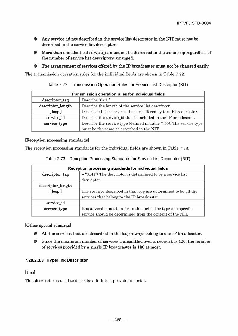
IPTVFJ STD-0004
—265—
Any service_id not described in the service list descriptor in the NIT must not be described in the service list descriptor.
More than one identical service_id must not be described in the same loop regardless of the number of service list descriptors arranged.
The arrangement of services offered by the IP broadcaster must not be changed easily.
The transmission operation rules for the individual fields are shown in Table 7-72.
Table 7-72 Transmission Operation Rules for Service List Descriptor (BIT)
Transmission operation rules for individual fields descriptor_tag Describe “0x41”.
descriptor_length Describe the length of the service list descriptor. [ loop ] Describe all the services that are offered by the IP broadcaster.
service_id Describe the service_id that is included in the IP broadcaster. service_type Describe the service type (defined in Table 7-55). The service type
must be the same as described in the NIT.
[Reception processing standards]
The reception processing standards for the individual fields are shown in Table 7-73.
Table 7-73 Reception Processing Standards for Service List Descriptor (BIT)
Reception processing standards for individual fields descriptor_tag = “0x41”: The descriptor is determined to be a service list
descriptor. descriptor_length
[ loop ] The services described in this loop are determined to be all the services that belong to the IP broadcaster.
service_id service_type It is advisable not to refer to this field. The type of a specific
service should be determined from the content of the NIT.
[Other special remarks]
All the services that are described in the loop always belong to one IP broadcaster.
Since the maximum number of services transmitted over a network is 120, the number of services provided by a single IP broadcaster is 120 at most.
7.28.2.3.3 Hyperlink Descriptor
[Use]
This descriptor is used to describe a link to a provider’s portal.

IPTVFJ STD-0004
-266-
[Structure]
For the structure of the hyperlink descriptor, see Table 7-74. When describing a URI, the hyper linkage type and link destination type in the hyperlink descriptor shall be described in accordance with ARIB STD-B10.
Table 7-74 Structure of Hyperlink Descriptor
Data structure bit Identifier hyperlink_descriptor(){ descriptor_tag 8 uimsbf descriptor_length 8 uimsbf hyper_linkage_type 8 uimsbf link_destination_type 8 uimsbf selector_length 8 uimsbf for(i=0;i<selector_length;i++){ Selector_byte 8 uimsbf } for(i=0;i<N;i++){ private_data 8 uimsbf } }
[Meaning of each field]
In accordance with the specifications defined in 6.2 “Data Structure of Descriptor” of ARIB STD-B10 Part 1, the meaning of each of the descriptor fields shall be as defined in 6.2.29 “Hyperlink Descriptor” of ARIB STD-B10 Part 2.
[Transmission operation rules]
This descriptor shall be arranged in the 2nd loop, and the URI of the link destination BML document that is described shall be applied to all the services within the network.
The link destination BML document indicated by the URI described must actually exist. If said BML document is absent, this descriptor must not be arranged.
The URI of the link destination BML document that is described shall be limited to the BML documents on the service provider’s portal managed by the platform provider, and only one URI beginning with http:// or https:// can be arranged in one loop.
Table 7-75 Transmission Operation Rules for Hyperlink Descriptor
Transmission operation rules for individual fields
descriptor_tag Describe “0xC5”.
descriptor_length Describe the length of the hyperlink descriptor. hyper_linkage_type Describe the hyper linkage type “0x09”.
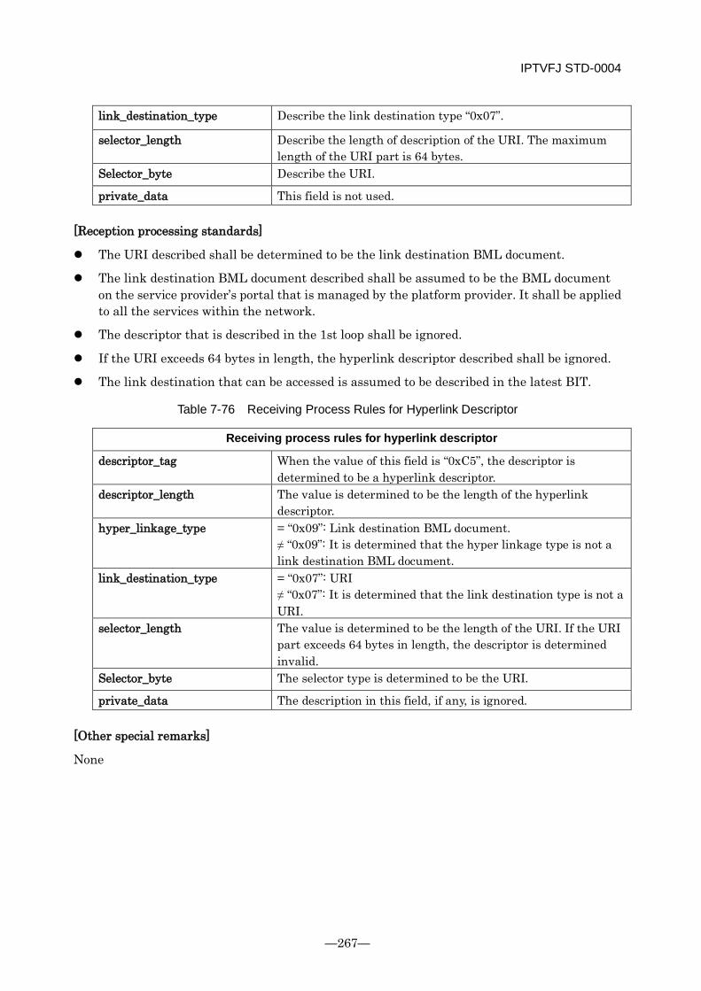
IPTVFJ STD-0004
—267—
link_destination_type Describe the link destination type “0x07”.
selector_length Describe the length of description of the URI. The maximum length of the URI part is 64 bytes.
Selector_byte Describe the URI.
private_data This field is not used.
[Reception processing standards]
The URI described shall be determined to be the link destination BML document.
The link destination BML document described shall be assumed to be the BML document on the service provider’s portal that is managed by the platform provider. It shall be applied to all the services within the network.
The descriptor that is described in the 1st loop shall be ignored.
If the URI exceeds 64 bytes in length, the hyperlink descriptor described shall be ignored.
The link destination that can be accessed is assumed to be described in the latest BIT.
Table 7-76 Receiving Process Rules for Hyperlink Descriptor
Receiving process rules for hyperlink descriptor
descriptor_tag When the value of this field is “0xC5”, the descriptor is determined to be a hyperlink descriptor.
descriptor_length The value is determined to be the length of the hyperlink descriptor.
hyper_linkage_type = “0x09”: Link destination BML document. ≠ “0x09”: It is determined that the hyper linkage type is not a link destination BML document.
link_destination_type = “0x07”: URI ≠ “0x07”: It is determined that the link destination type is not a URI.
selector_length The value is determined to be the length of the URI. If the URI part exceeds 64 bytes in length, the descriptor is determined invalid.
Selector_byte The selector type is determined to be the URI.
private_data The description in this field, if any, is ignored.
[Other special remarks]
None
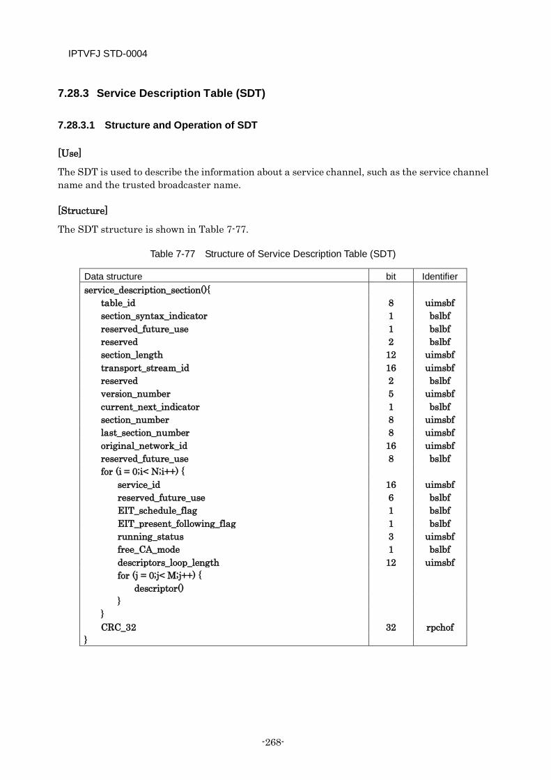
IPTVFJ STD-0004
-268-
7.28.3 Service Description Table (SDT)
7.28.3.1 Structure and Operation of SDT
[Use]
The SDT is used to describe the information about a service channel, such as the service channel name and the trusted broadcaster name.
[Structure]
The SDT structure is shown in Table 7-77.
Table 7-77 Structure of Service Description Table (SDT)
Data structure bit Identifier service_description_section(){
table_id 8 uimsbf section_syntax_indicator 1 bslbf reserved_future_use 1 bslbf reserved 2 bslbf section_length 12 uimsbf transport_stream_id 16 uimsbf reserved 2 bslbf version_number 5 uimsbf current_next_indicator 1 bslbf section_number 8 uimsbf last_section_number 8 uimsbf original_network_id 16 uimsbf reserved_future_use 8 bslbf for (i = 0;i< N;i++) {
service_id 16 uimsbf reserved_future_use 6 bslbf EIT_schedule_flag 1 bslbf EIT_present_following_flag 1 bslbf running_status 3 uimsbf free_CA_mode 1 bslbf descriptors_loop_length 12 uimsbf for (j = 0;j< M;j++) {
descriptor() }
} CRC_32 32 rpchof
}
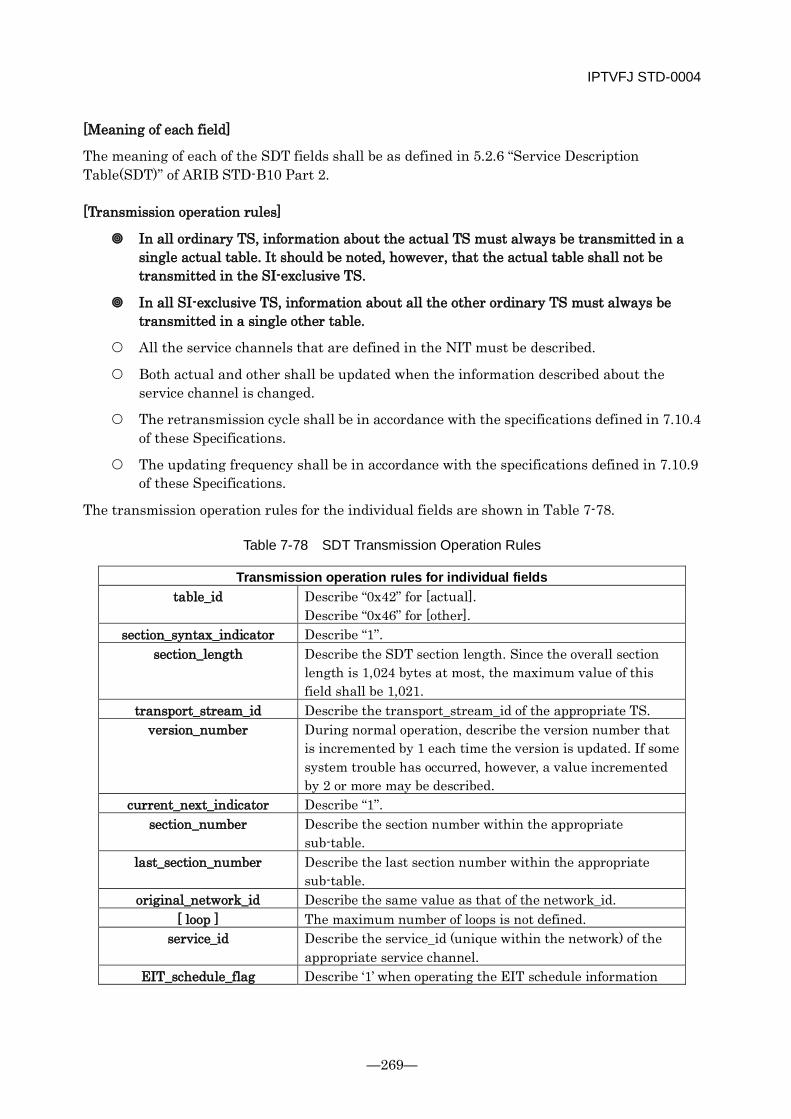
IPTVFJ STD-0004
—269—
[Meaning of each field]
The meaning of each of the SDT fields shall be as defined in 5.2.6 “Service Description Table(SDT)” of ARIB STD-B10 Part 2.
[Transmission operation rules]
In all ordinary TS, information about the actual TS must always be transmitted in a single actual table. It should be noted, however, that the actual table shall not be transmitted in the SI-exclusive TS.
In all SI-exclusive TS, information about all the other ordinary TS must always be transmitted in a single other table.
All the service channels that are defined in the NIT must be described.
Both actual and other shall be updated when the information described about the service channel is changed.
The retransmission cycle shall be in accordance with the specifications defined in 7.10.4 of these Specifications.
The updating frequency shall be in accordance with the specifications defined in 7.10.9 of these Specifications.
The transmission operation rules for the individual fields are shown in Table 7-78.
Table 7-78 SDT Transmission Operation Rules
Transmission operation rules for individual fields table_id Describe “0x42” for [actual].
Describe “0x46” for [other]. section_syntax_indicator Describe “1”.
section_length Describe the SDT section length. Since the overall section length is 1,024 bytes at most, the maximum value of this field shall be 1,021.
transport_stream_id Describe the transport_stream_id of the appropriate TS. version_number During normal operation, describe the version number that
is incremented by 1 each time the version is updated. If some system trouble has occurred, however, a value incremented by 2 or more may be described.
current_next_indicator Describe “1”. section_number Describe the section number within the appropriate
sub-table. last_section_number Describe the last section number within the appropriate
sub-table. original_network_id Describe the same value as that of the network_id.
[ loop ] The maximum number of loops is not defined. service_id Describe the service_id (unique within the network) of the
appropriate service channel. EIT_schedule_flag Describe ‘1’ when operating the EIT schedule information
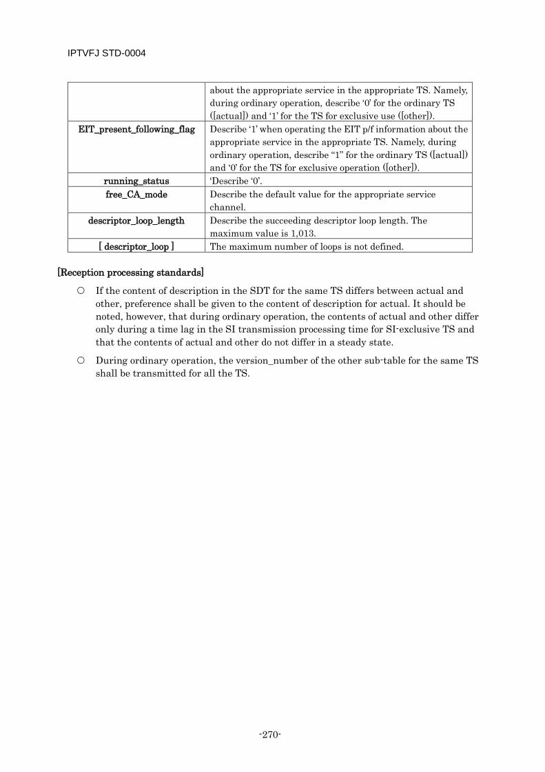
IPTVFJ STD-0004
-270-
about the appropriate service in the appropriate TS. Namely, during ordinary operation, describe ‘0’ for the ordinary TS ([actual]) and ‘1’ for the TS for exclusive use ([other]).
EIT_present_following_flag Describe ‘1’ when operating the EIT p/f information about the appropriate service in the appropriate TS. Namely, during ordinary operation, describe “1” for the ordinary TS ([actual]) and ‘0’ for the TS for exclusive operation ([other]).
running_status ‘Describe ‘0’. free_CA_mode Describe the default value for the appropriate service
channel. descriptor_loop_length Describe the succeeding descriptor loop length. The
maximum value is 1,013. [ descriptor_loop ] The maximum number of loops is not defined.
[Reception processing standards]
If the content of description in the SDT for the same TS differs between actual and other, preference shall be given to the content of description for actual. It should be noted, however, that during ordinary operation, the contents of actual and other differ only during a time lag in the SI transmission processing time for SI-exclusive TS and that the contents of actual and other do not differ in a steady state.
During ordinary operation, the version_number of the other sub-table for the same TS shall be transmitted for all the TS.
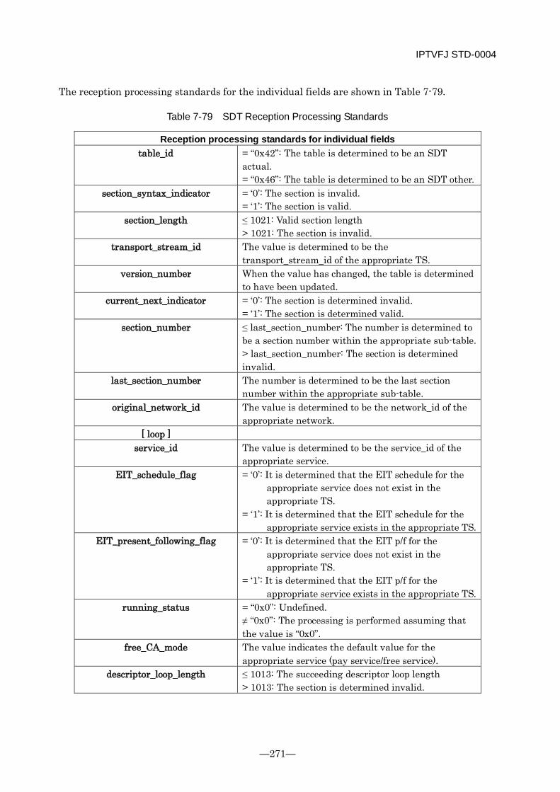
IPTVFJ STD-0004
—271—
The reception processing standards for the individual fields are shown in Table 7-79.
Table 7-79 SDT Reception Processing Standards
Reception processing standards for individual fields table_id = “0x42”: The table is determined to be an SDT
actual. = “0x46”: The table is determined to be an SDT other.
section_syntax_indicator = ‘0’: The section is invalid. = ‘1’: The section is valid.
section_length ≤ 1021: Valid section length > 1021: The section is invalid.
transport_stream_id The value is determined to be the transport_stream_id of the appropriate TS.
version_number When the value has changed, the table is determined to have been updated.
current_next_indicator = ‘0’: The section is determined invalid. = ‘1’: The section is determined valid.
section_number ≤ last_section_number: The number is determined to be a section number within the appropriate sub-table. > last_section_number: The section is determined invalid.
last_section_number The number is determined to be the last section number within the appropriate sub-table.
original_network_id The value is determined to be the network_id of the appropriate network.
[ loop ] service_id The value is determined to be the service_id of the
appropriate service. EIT_schedule_flag = ‘0’: It is determined that the EIT schedule for the
appropriate service does not exist in the appropriate TS.
= ‘1’: It is determined that the EIT schedule for the appropriate service exists in the appropriate TS.
EIT_present_following_flag = ‘0’: It is determined that the EIT p/f for the appropriate service does not exist in the appropriate TS.
= ‘1’: It is determined that the EIT p/f for the appropriate service exists in the appropriate TS.
running_status = “0x0”: Undefined. ≠ “0x0”: The processing is performed assuming that the value is “0x0”.
free_CA_mode The value indicates the default value for the appropriate service (pay service/free service).
descriptor_loop_length ≤ 1013: The succeeding descriptor loop length > 1013: The section is determined invalid.
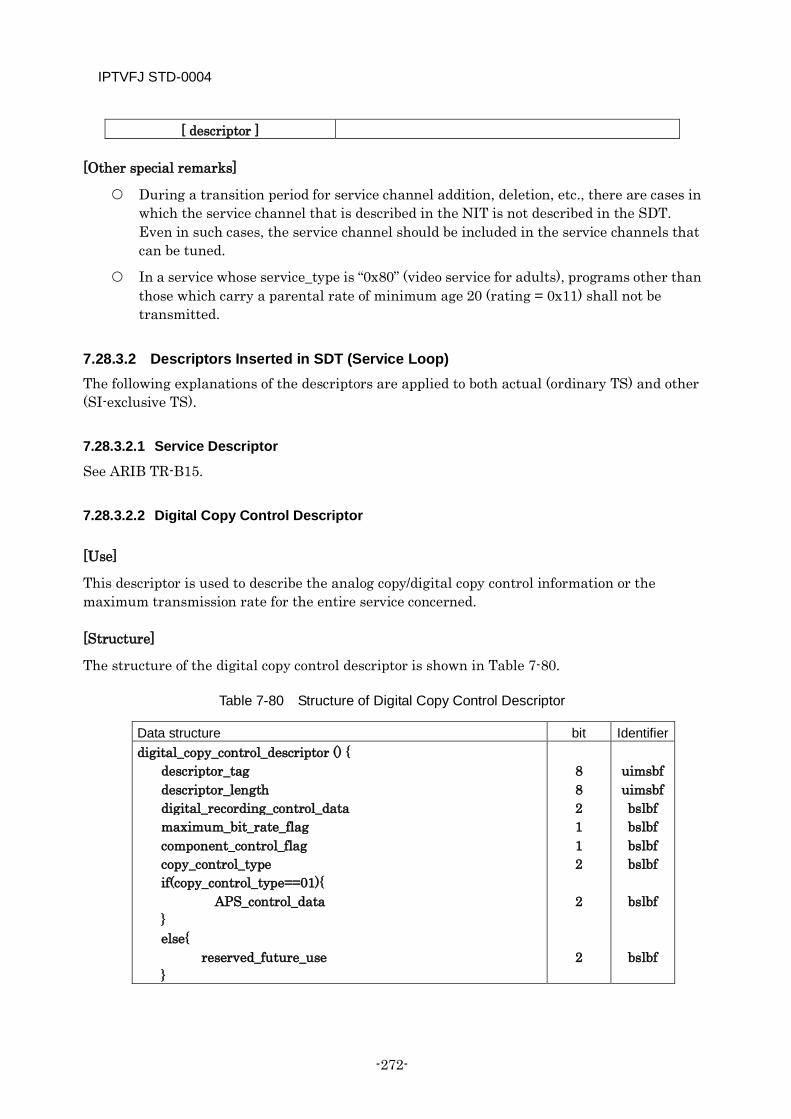
IPTVFJ STD-0004
-272-
[ descriptor ]
[Other special remarks]
During a transition period for service channel addition, deletion, etc., there are cases in which the service channel that is described in the NIT is not described in the SDT. Even in such cases, the service channel should be included in the service channels that can be tuned.
In a service whose service_type is “0x80” (video service for adults), programs other than those which carry a parental rate of minimum age 20 (rating = 0x11) shall not be transmitted.
7.28.3.2 Descriptors Inserted in SDT (Service Loop) The following explanations of the descriptors are applied to both actual (ordinary TS) and other (SI-exclusive TS).
7.28.3.2.1 Service Descriptor
See ARIB TR-B15.
7.28.3.2.2 Digital Copy Control Descriptor
[Use]
This descriptor is used to describe the analog copy/digital copy control information or the maximum transmission rate for the entire service concerned.
[Structure]
The structure of the digital copy control descriptor is shown in Table 7-80.
Table 7-80 Structure of Digital Copy Control Descriptor
Data structure bit Identifier digital_copy_control_descriptor () {
descriptor_tag 8 uimsbf descriptor_length 8 uimsbf digital_recording_control_data 2 bslbf maximum_bit_rate_flag 1 bslbf component_control_flag 1 bslbf copy_control_type if(copy_control_type==01){ APS_control_data } else{ reserved_future_use }
2 2 2
bslbf
bslbf
bslbf
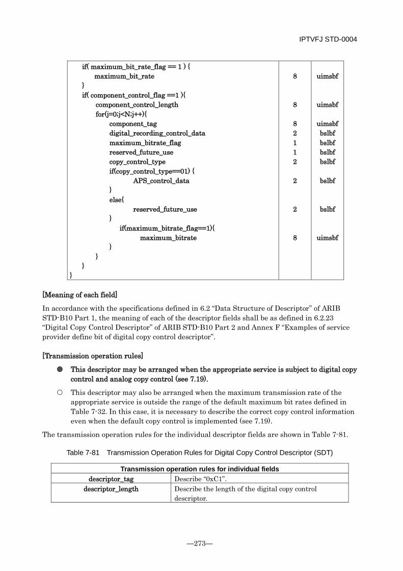
IPTVFJ STD-0004
—273—
if( maximum_bit_rate_flag == 1 ) { maximum_bit_rate 8 uimsbf
} if( component_control_flag ==1 ){ component_control_length 8 uimsbf for(j=0;j<N;j++){ component_tag 8 uimsbf digital_recording_control_data 2 bslbf maximum_bitrate_flag 1 bslbf reserved_future_use 1 bslbf copy_control_type if(copy_control_type==01) { APS_control_data } else{ reserved_future_use }
2 2 2
bslbf
bslbf
bslbf
if(maximum_bitrate_flag==1){ maximum_bitrate 8 uimsbf } } }
}
[Meaning of each field]
In accordance with the specifications defined in 6.2 “Data Structure of Descriptor” of ARIB STD-B10 Part 1, the meaning of each of the descriptor fields shall be as defined in 6.2.23 “Digital Copy Control Descriptor” of ARIB STD-B10 Part 2 and Annex F “Examples of service provider define bit of digital copy control descriptor”.
[Transmission operation rules]
This descriptor may be arranged when the appropriate service is subject to digital copy control and analog copy control (see 7.19).
This descriptor may also be arranged when the maximum transmission rate of the appropriate service is outside the range of the default maximum bit rates defined in Table 7-32. In this case, it is necessary to describe the correct copy control information even when the default copy control is implemented (see 7.19).
The transmission operation rules for the individual descriptor fields are shown in Table 7-81.
Table 7-81 Transmission Operation Rules for Digital Copy Control Descriptor (SDT)
Transmission operation rules for individual fields descriptor_tag Describe “0xC1”.
descriptor_length Describe the length of the digital copy control descriptor.
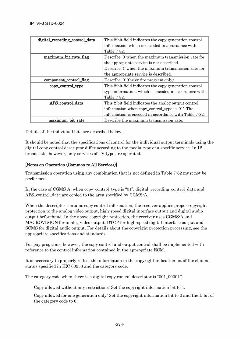
IPTVFJ STD-0004
-274-
digital_recording_control_data This 2-bit field indicates the copy generation control information, which is encoded in accordance with Table 7-82.
maximum_bit_rate_flag Describe ‘0’ when the maximum transmission rate for the appropriate service is not described. Describe ‘1’ when the maximum transmission rate for the appropriate service is described.
component_control_flag Describe ‘0’ (the entire program only). copy_control_type This 2-bit field indicates the copy generation control
type information, which is encoded in accordance with Table 7-82.
APS_control_data This 2-bit field indicates the analog output control information when copy_control_type is ‘01’. The information is encoded in accordance with Table 7-82.
maximum_bit_rate Describe the maximum transmission rate. Details of the individual bits are described below.
It should be noted that the specifications of control for the individual output terminals using the digital copy control descriptor differ according to the media type of a specific service. In IP broadcasts, however, only services of TV type are operated.
[Notes on Operation (Common to All Services)]
Transmission operation using any combination that is not defined in Table 7-82 must not be performed.
In the case of CGMS-A, when copy_control_type is “01”, digital_recording_control_data and APS_control_data are copied to the area specified by CGMS-A.
When the descriptor contains copy control information, the receiver applies proper copyright protection to the analog video output, high-speed digital interface output and digital audio output beforehand. In the above copyright protection, the receiver uses CGMS-A and MACROVISION for analog video output, DTCP for high-speed digital interface output and SCMS for digital audio output. For details about the copyright protection processing, see the appropriate specifications and standards.
For pay programs, however, the copy control and output control shall be implemented with reference to the control information contained in the appropriate ECM.
It is necessary to properly reflect the information in the copyright indication bit of the channel status specified in IEC 60958 and the category code.
The category code when there is a digital copy control descriptor is “001_0000L”.
Copy allowed without any restrictions: Set the copyright information bit to 1.
Copy allowed for one generation only: Set the copyright information bit to 0 and the L-bit of the category code to 0.
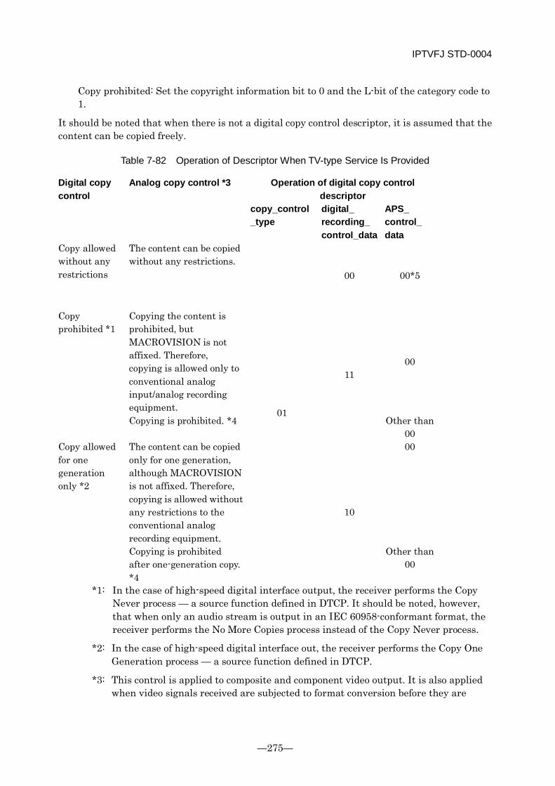
IPTVFJ STD-0004
—275—
Copy prohibited: Set the copyright information bit to 0 and the L-bit of the category code to 1.
It should be noted that when there is not a digital copy control descriptor, it is assumed that the content can be copied freely.
Table 7-82 Operation of Descriptor When TV-type Service Is Provided
Digital copy control
Analog copy control *3 Operation of digital copy control descriptor
copy_control_type
digital_ recording_ control_data
APS_ control_ data
Copy allowed without any restrictions
The content can be copied without any restrictions.
01
00 00*5
Copy prohibited *1
Copying the content is prohibited, but MACROVISION is not affixed. Therefore, copying is allowed only to conventional analog input/analog recording equipment.
11 00
Copying is prohibited. *4 Other than 00
Copy allowed for one generation only *2
The content can be copied only for one generation, although MACROVISION is not affixed. Therefore, copying is allowed without any restrictions to the conventional analog recording equipment.
10
00
Copying is prohibited after one-generation copy. *4
Other than 00
*1: In the case of high-speed digital interface output, the receiver performs the Copy Never process — a source function defined in DTCP. It should be noted, however, that when only an audio stream is output in an IEC 60958-conformant format, the receiver performs the No More Copies process instead of the Copy Never process.
*2: In the case of high-speed digital interface out, the receiver performs the Copy One Generation process — a source function defined in DTCP.
*3: This control is applied to composite and component video output. It is also applied when video signals received are subjected to format conversion before they are
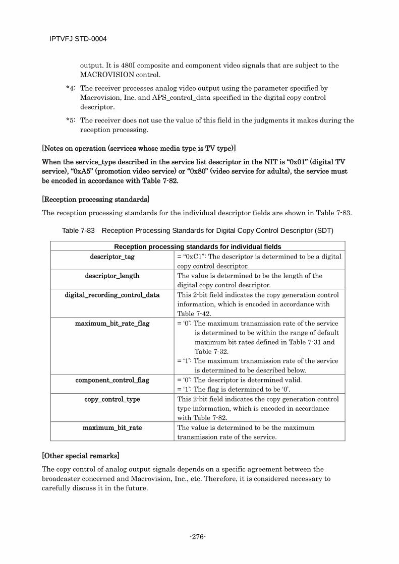
IPTVFJ STD-0004
-276-
output. It is 480I composite and component video signals that are subject to the MACROVISION control.
*4: The receiver processes analog video output using the parameter specified by Macrovision, Inc. and APS_control_data specified in the digital copy control descriptor.
*5: The receiver does not use the value of this field in the judgments it makes during the reception processing.
[Notes on operation (services whose media type is TV type)]
When the service_type described in the service list descriptor in the NIT is “0x01” (digital TV service), “0xA5” (promotion video service) or “0x80” (video service for adults), the service must be encoded in accordance with Table 7-82.
[Reception processing standards]
The reception processing standards for the individual descriptor fields are shown in Table 7-83.
Table 7-83 Reception Processing Standards for Digital Copy Control Descriptor (SDT)
Reception processing standards for individual fields descriptor_tag = “0xC1”: The descriptor is determined to be a digital
copy control descriptor. descriptor_length The value is determined to be the length of the
digital copy control descriptor. digital_recording_control_data This 2-bit field indicates the copy generation control
information, which is encoded in accordance with Table 7-42.
maximum_bit_rate_flag = ‘0’: The maximum transmission rate of the service is determined to be within the range of default maximum bit rates defined in Table 7-31 and Table 7-32.
= ‘1’: The maximum transmission rate of the service is determined to be described below.
component_control_flag = ‘0’: The descriptor is determined valid. = ‘1’: The flag is determined to be ‘0’.
copy_control_type This 2-bit field indicates the copy generation control type information, which is encoded in accordance with Table 7-82.
maximum_bit_rate The value is determined to be the maximum transmission rate of the service.
[Other special remarks]
The copy control of analog output signals depends on a specific agreement between the broadcaster concerned and Macrovision, Inc., etc. Therefore, it is considered necessary to carefully discuss it in the future.
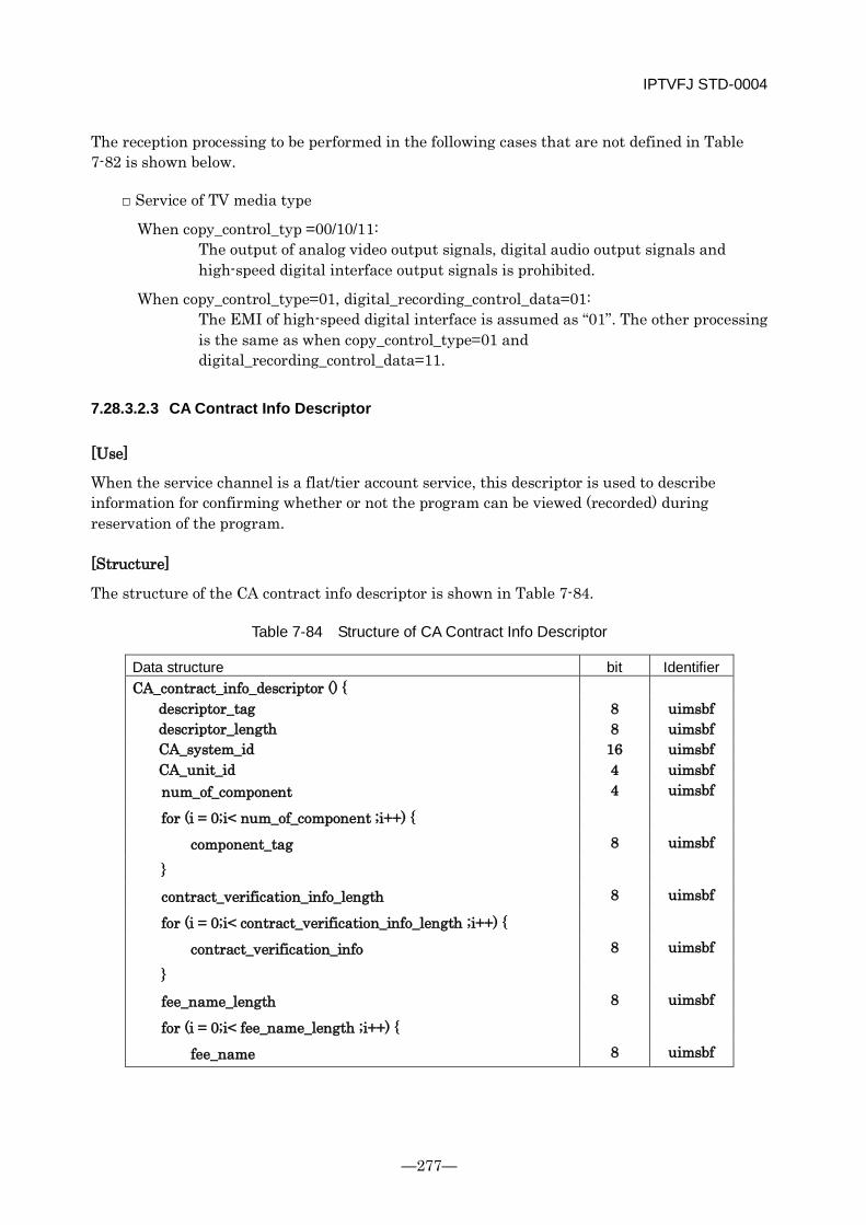
IPTVFJ STD-0004
—277—
The reception processing to be performed in the following cases that are not defined in Table 7-82 is shown below.
□ Service of TV media type
When copy_control_typ =00/10/11: The output of analog video output signals, digital audio output signals and high-speed digital interface output signals is prohibited.
When copy_control_type=01, digital_recording_control_data=01: The EMI of high-speed digital interface is assumed as “01”. The other processing is the same as when copy_control_type=01 and digital_recording_control_data=11.
7.28.3.2.3 CA Contract Info Descriptor
[Use]
When the service channel is a flat/tier account service, this descriptor is used to describe information for confirming whether or not the program can be viewed (recorded) during reservation of the program.
[Structure]
The structure of the CA contract info descriptor is shown in Table 7-84.
Table 7-84 Structure of CA Contract Info Descriptor
Data structure bit Identifier CA_contract_info_descriptor () {
descriptor_tag 8 uimsbf descriptor_length 8 uimsbf CA_system_id 16 uimsbf CA_unit_id 4 uimsbf num_of_component 4 uimsbf
for (i = 0;i< num_of_component ;i++) {
component_tag 8 uimsbf
}
contract_verification_info_length 8 uimsbf
for (i = 0;i< contract_verification_info_length ;i++) {
contract_verification_info 8 uimsbf
}
fee_name_length 8 uimsbf
for (i = 0;i< fee_name_length ;i++) {
fee_name 8 uimsbf

IPTVFJ STD-0004
-278-
}
}
[Meaning of each field]
The meaning of each of the descriptor fields is defined below.
Table 7-85 Meaning of Each Field of CA Contract Info Descriptor
Meaning of each field CA_system_id This 8-bit field indicates the conditional access system
identifier, which is specified by the Minister of Public Management, Home Affairs, Posts and Telecommunications.
CA_unit_id This 4-bit field identifies the account unit/non-account unit to which the component belongs. It should be noted that only 0x1 is used in this descriptor. 0x0: Non-account unit group 0x1: Account unit group including default ES group of events 0x2-0xF: Account unit group other than the one shown above
num_of_component This 4-bit field indicates the number of components which belong to the account unit specified by CA_unit_id.
[component_tag] This 8-bit field is a label for identification of a specific component stream in the account unit specified by CA_unit_id. When a stream identifier descriptor is contained in the PMT, the value of the label is the same as that of the component tag described in the stream identifier descriptor.
contract_verification_info_length This 8-bit field indicates the length in bytes of the contract verification information that follows.
[contract_verification_info] This is an 8-bit field. A series of verification information fields describe contract verification information. This field describes the data structure shown in Table 7-86.
fee_name_length This 8-bit field indicates the length in bytes of the fee name that follows.
[fee_name] This is an 8-bit field. A series of fee name fields describe fee names.
Table 7-86 Data Structure of Contract Verification Information
Data structure bit Identifier contract_verification_info() {
license_id 64 uimsbf tier_bit_mask 64 bslbf

IPTVFJ STD-0004
—279—
}
Table 7-87 Meanings of Fields in Data Structure Shown in Table 7-86
Meanings of individual fields license_id The license ID of the MC license associated with the contract
(defined in Chapter 6). tier_bit_mask The mask information on the tier bit string of the MC license
associated with the contract.
[Transmission operation rules]
In IP broadcasts, there is only one account unit. Therefore, only one CA_unit_id shall be inserted when necessary.
When free_CA_mode = 0, the CA contract info descriptor with CA_unit_id=0x1 must not be arranged.
When free_CA_mode is 1, the CA contract info descriptor with CA_unit_id=0x1 must be arranged.
As far as possible, no value shall be changed once set.
The transmission operation rules for the individual descriptor fields are shown in Table 7-88.
Table 7-88 Transmission Operation Rules for CA Contract Info Descriptor (SDT)
Transmission operation rules for individual fields descriptor_tag Describe “0xCB”.
descriptor_length Describe the length of the CA contract info descriptor. CA_system_id Describe the conditional access system identifier. Any value
other than the identifier values applied in IP broadcasts must not be described.
CA_unit_id Describe the account unit identifier. Only 0x01 shall be used. num_of_component Describe the number of components to which the account unit is
applied. The maximum number is 4. [component_tag] Describe the tag values of the components to which the account
unit is applied. contract_verification
_info_length Describe the length of contract verification information. In IP broadcasts, it is always 16.
[contract_verification _info]
Describe the contract verification information.
fee_name_length In IP broadcasts, always set the length to 0. [fee_name] In IP broadcasts, this field is not used.
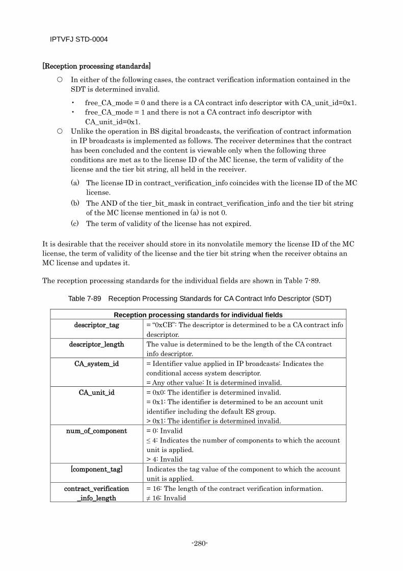
IPTVFJ STD-0004
-280-
[Reception processing standards]
In either of the following cases, the contract verification information contained in the SDT is determined invalid.
• free_CA_mode = 0 and there is a CA contract info descriptor with CA_unit_id=0x1. • free_CA_mode = 1 and there is not a CA contract info descriptor with
CA_unit_id=0x1. Unlike the operation in BS digital broadcasts, the verification of contract information
in IP broadcasts is implemented as follows. The receiver determines that the contract has been concluded and the content is viewable only when the following three conditions are met as to the license ID of the MC license, the term of validity of the license and the tier bit string, all held in the receiver.
(a) The license ID in contract_verification_info coincides with the license ID of the MC license.
(b) The AND of the tier_bit_mask in contract_verification_info and the tier bit string of the MC license mentioned in (a) is not 0.
(c) The term of validity of the license has not expired. It is desirable that the receiver should store in its nonvolatile memory the license ID of the MC license, the term of validity of the license and the tier bit string when the receiver obtains an MC license and updates it.
The reception processing standards for the individual fields are shown in Table 7-89.
Table 7-89 Reception Processing Standards for CA Contract Info Descriptor (SDT)
Reception processing standards for individual fields descriptor_tag = “0xCB”: The descriptor is determined to be a CA contract info
descriptor. descriptor_length The value is determined to be the length of the CA contract
info descriptor. CA_system_id = Identifier value applied in IP broadcasts: Indicates the
conditional access system descriptor. = Any other value: It is determined invalid.
CA_unit_id = 0x0: The identifier is determined invalid. = 0x1: The identifier is determined to be an account unit identifier including the default ES group. > 0x1: The identifier is determined invalid.
num_of_component = 0: Invalid ≤ 4: Indicates the number of components to which the account unit is applied. > 4: Invalid
[component_tag] Indicates the tag value of the component to which the account unit is applied.
contract_verification _info_length
= 16: The length of the contract verification information. ≠ 16: Invalid
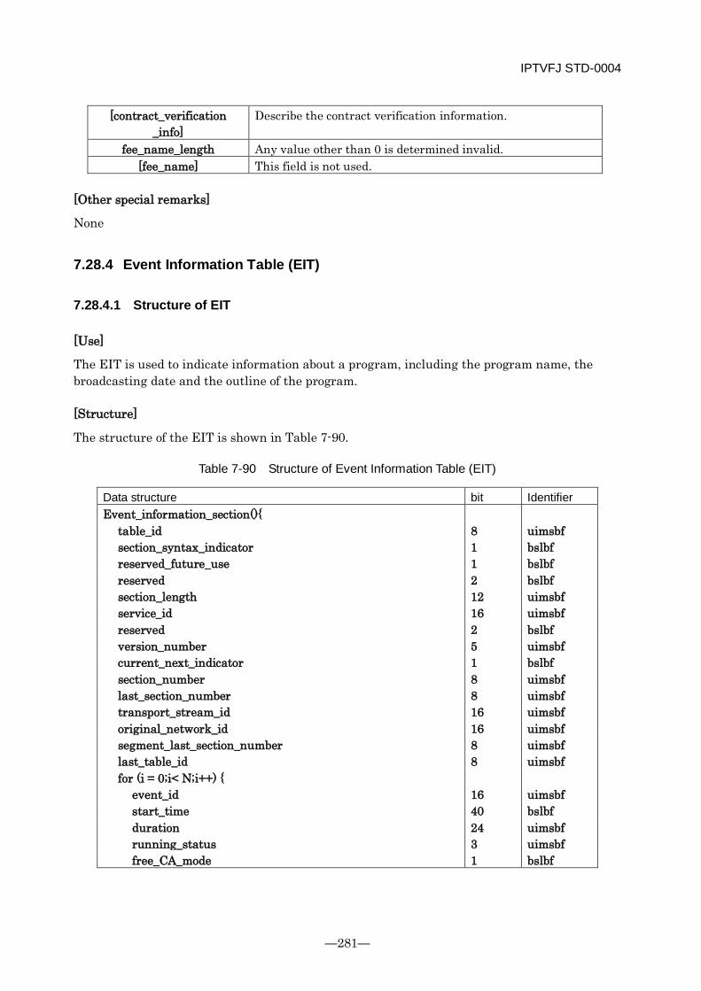
IPTVFJ STD-0004
—281—
[contract_verification _info]
Describe the contract verification information.
fee_name_length Any value other than 0 is determined invalid. [fee_name] This field is not used.
[Other special remarks]
None
7.28.4 Event Information Table (EIT)
7.28.4.1 Structure of EIT
[Use]
The EIT is used to indicate information about a program, including the program name, the broadcasting date and the outline of the program.
[Structure]
The structure of the EIT is shown in Table 7-90.
Table 7-90 Structure of Event Information Table (EIT)
Data structure bit Identifier Event_information_section(){
table_id 8 uimsbf section_syntax_indicator 1 bslbf reserved_future_use 1 bslbf reserved 2 bslbf section_length 12 uimsbf service_id 16 uimsbf reserved 2 bslbf version_number 5 uimsbf current_next_indicator 1 bslbf section_number 8 uimsbf last_section_number 8 uimsbf transport_stream_id 16 uimsbf original_network_id 16 uimsbf segment_last_section_number 8 uimsbf last_table_id 8 uimsbf for (i = 0;i< N;i++) {
event_id 16 uimsbf start_time 40 bslbf duration 24 uimsbf running_status 3 uimsbf free_CA_mode 1 bslbf
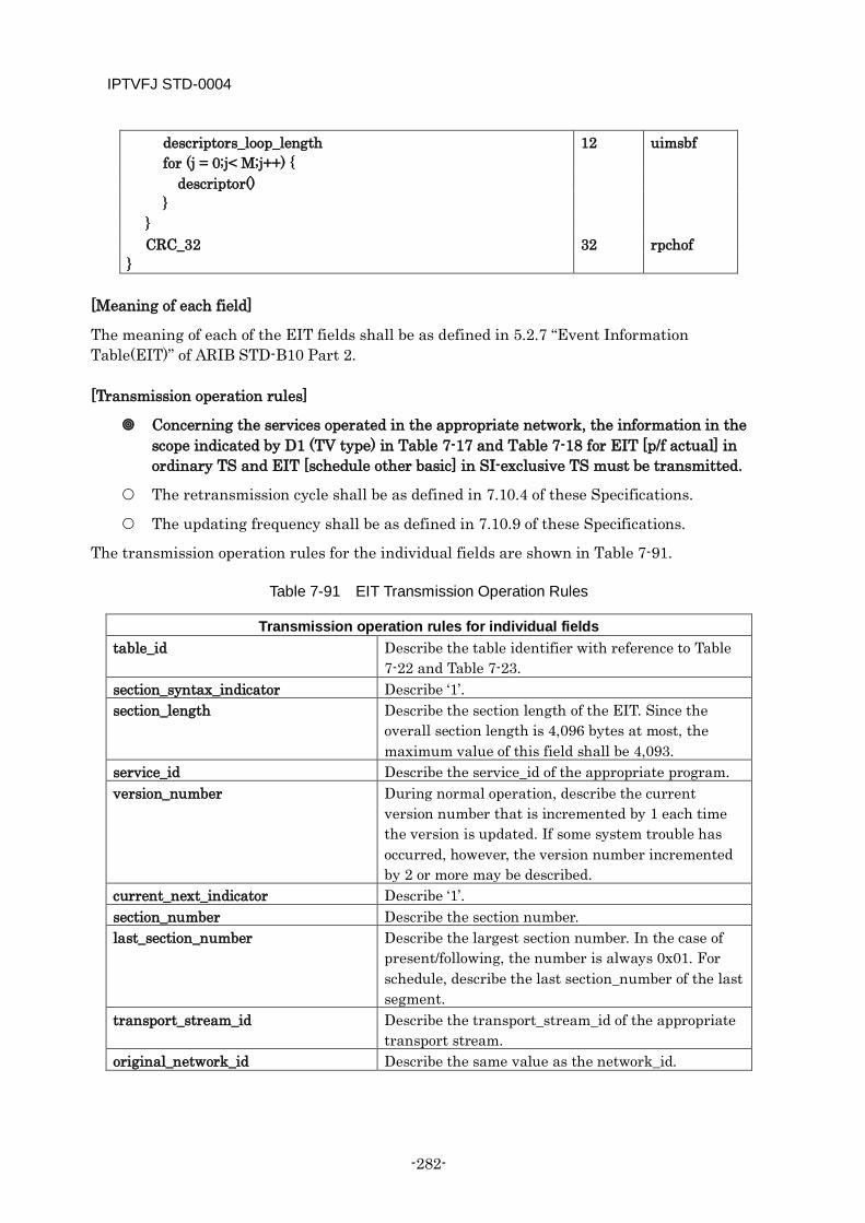
IPTVFJ STD-0004
-282-
descriptors_loop_length 12 uimsbf for (j = 0;j< M;j++) { descriptor() }
} CRC_32 32 rpchof
}
[Meaning of each field]
The meaning of each of the EIT fields shall be as defined in 5.2.7 “Event Information Table(EIT)” of ARIB STD-B10 Part 2.
[Transmission operation rules]
Concerning the services operated in the appropriate network, the information in the scope indicated by D1 (TV type) in Table 7-17 and Table 7-18 for EIT [p/f actual] in ordinary TS and EIT [schedule other basic] in SI-exclusive TS must be transmitted.
The retransmission cycle shall be as defined in 7.10.4 of these Specifications.
The updating frequency shall be as defined in 7.10.9 of these Specifications.
The transmission operation rules for the individual fields are shown in Table 7-91.
Table 7-91 EIT Transmission Operation Rules
Transmission operation rules for individual fields table_id Describe the table identifier with reference to Table
7-22 and Table 7-23. section_syntax_indicator Describe ‘1’. section_length Describe the section length of the EIT. Since the
overall section length is 4,096 bytes at most, the maximum value of this field shall be 4,093.
service_id Describe the service_id of the appropriate program. version_number During normal operation, describe the current
version number that is incremented by 1 each time the version is updated. If some system trouble has occurred, however, the version number incremented by 2 or more may be described.
current_next_indicator Describe ‘1’. section_number Describe the section number. last_section_number Describe the largest section number. In the case of
present/following, the number is always 0x01. For schedule, describe the last section_number of the last segment.
transport_stream_id Describe the transport_stream_id of the appropriate transport stream.
original_network_id Describe the same value as the network_id.
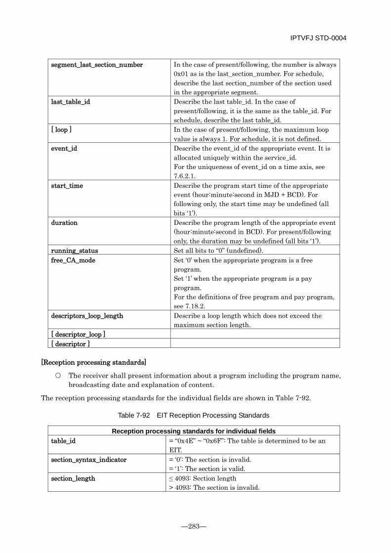
IPTVFJ STD-0004
—283—
segment_last_section_number In the case of present/following, the number is always 0x01 as is the last_section_number. For schedule, describe the last section_number of the section used in the appropriate segment.
last_table_id Describe the last table_id. In the case of present/following, it is the same as the table_id. For schedule, describe the last table_id.
[ loop ] In the case of present/following, the maximum loop value is always 1. For schedule, it is not defined.
event_id Describe the event_id of the appropriate event. It is allocated uniquely within the service_id. For the uniqueness of event_id on a time axis, see 7.6.2.1.
start_time Describe the program start time of the appropriate event (hour:minute:second in MJD + BCD). For following only, the start time may be undefined (all bits ‘1’).
duration Describe the program length of the appropriate event (hour:minute:second in BCD). For present/following only, the duration may be undefined (all bits ‘1’).
running_status Set all bits to “0” (undefined). free_CA_mode Set ‘0’ when the appropriate program is a free
program. Set ‘1’ when the appropriate program is a pay program. For the definitions of free program and pay program, see 7.18.2.
descriptors_loop_length Describe a loop length which does not exceed the maximum section length.
[ descriptor_loop ] [ descriptor ]
[Reception processing standards]
The receiver shall present information about a program including the program name, broadcasting date and explanation of content.
The reception processing standards for the individual fields are shown in Table 7-92.
Table 7-92 EIT Reception Processing Standards
Reception processing standards for individual fields table_id = “0x4E” ~ “0x6F”: The table is determined to be an
EIT. section_syntax_indicator = ‘0’: The section is invalid.
= ‘1’: The section is valid. section_length ≤ 4093: Section length
> 4093: The section is invalid.
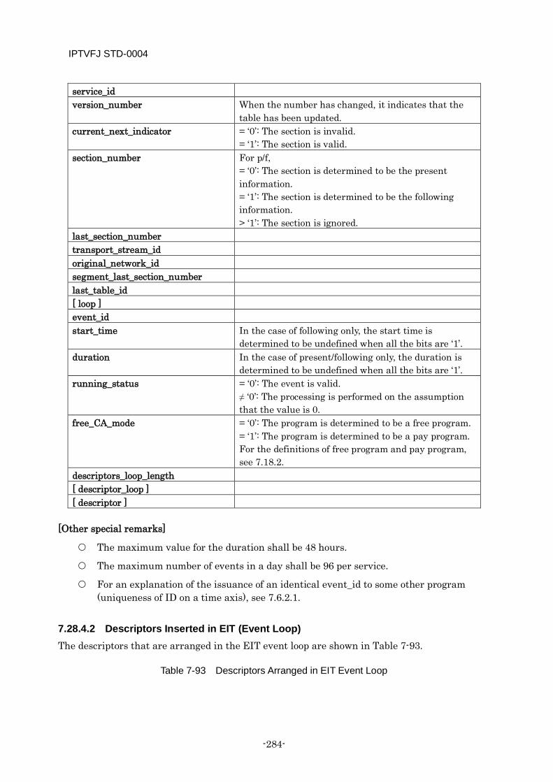
IPTVFJ STD-0004
-284-
service_id version_number When the number has changed, it indicates that the
table has been updated. current_next_indicator = ‘0’: The section is invalid.
= ‘1’: The section is valid. section_number For p/f,
= ‘0’: The section is determined to be the present information. = ‘1’: The section is determined to be the following information. > ‘1’: The section is ignored.
last_section_number transport_stream_id original_network_id segment_last_section_number last_table_id [ loop ] event_id start_time In the case of following only, the start time is
determined to be undefined when all the bits are ‘1’. duration In the case of present/following only, the duration is
determined to be undefined when all the bits are ‘1’. running_status = ‘0’: The event is valid.
≠ ‘0’: The processing is performed on the assumption that the value is 0.
free_CA_mode = ‘0’: The program is determined to be a free program. = ‘1’: The program is determined to be a pay program. For the definitions of free program and pay program, see 7.18.2.
descriptors_loop_length [ descriptor_loop ] [ descriptor ]
[Other special remarks]
The maximum value for the duration shall be 48 hours.
The maximum number of events in a day shall be 96 per service.
For an explanation of the issuance of an identical event_id to some other program (uniqueness of ID on a time axis), see 7.6.2.1.
7.28.4.2 Descriptors Inserted in EIT (Event Loop) The descriptors that are arranged in the EIT event loop are shown in Table 7-93.
Table 7-93 Descriptors Arranged in EIT Event Loop
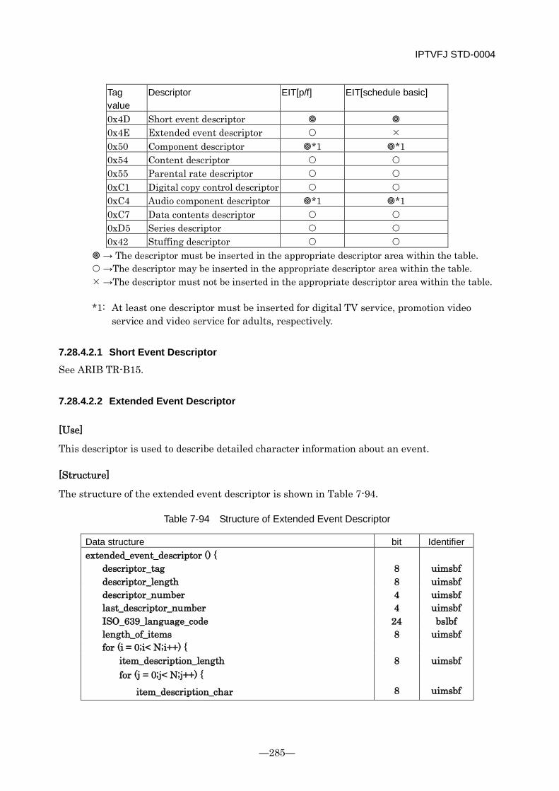
IPTVFJ STD-0004
—285—
Tag value
Descriptor EIT[p/f] EIT[schedule basic]
0x4D Short event descriptor 0x4E Extended event descriptor 0x50 Component descriptor *1 *1 0x54 Content descriptor 0x55 Parental rate descriptor 0xC1 Digital copy control descriptor 0xC4 Audio component descriptor *1 *1 0xC7 Data contents descriptor 0xD5 Series descriptor 0x42 Stuffing descriptor
→ The descriptor must be inserted in the appropriate descriptor area within the table. →The descriptor may be inserted in the appropriate descriptor area within the table. →The descriptor must not be inserted in the appropriate descriptor area within the table. *1: At least one descriptor must be inserted for digital TV service, promotion video
service and video service for adults, respectively.
7.28.4.2.1 Short Event Descriptor
See ARIB TR-B15.
7.28.4.2.2 Extended Event Descriptor
[Use]
This descriptor is used to describe detailed character information about an event.
[Structure]
The structure of the extended event descriptor is shown in Table 7-94.
Table 7-94 Structure of Extended Event Descriptor
Data structure bit Identifier extended_event_descriptor () {
descriptor_tag 8 uimsbf descriptor_length 8 uimsbf descriptor_number 4 uimsbf last_descriptor_number 4 uimsbf ISO_639_language_code 24 bslbf length_of_items 8 uimsbf for (i = 0;i< N;i++) {
item_description_length 8 uimsbf for (j = 0;j< N;j++) {
item_description_char 8 uimsbf
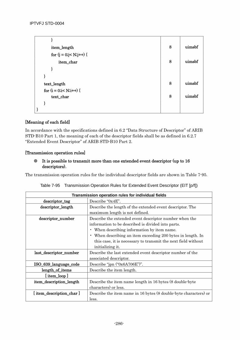
IPTVFJ STD-0004
-286-
}
item_length 8 uimsbf
for (j = 0;j< N;j++) {
item_char 8 uimsbf
}
}
text_length 8 uimsbf for (i = 0;i< N;i++) {
text_char 8 uimsbf }
}
[Meaning of each field]
In accordance with the specifications defined in 6.2 “Data Structure of Descriptor” of ARIB STD-B10 Part 1, the meaning of each of the descriptor fields shall be as defined in 6.2.7 “Extended Event Descriptor” of ARIB STD-B10 Part 2.
[Transmission operation rules]
It is possible to transmit more than one extended event descriptor (up to 16 descriptors).
The transmission operation rules for the individual descriptor fields are shown in Table 7-95.
Table 7-95 Transmission Operation Rules for Extended Event Descriptor (EIT [p/f])
Transmission operation rules for individual fields descriptor_tag Describe “0x4E”.
descriptor_length Describe the length of the extended event descriptor. The maximum length is not defined.
descriptor_number Describe the extended event descriptor number when the information to be described is divided into parts. • When describing information by item name. • When describing an item exceeding 200 bytes in length. In
this case, it is necessary to transmit the next field without initializing it.
last_descriptor_number Describe the last extended event descriptor number of the associated descriptor.
ISO_639_language_code Describe “jpn (“0x6A706E”)”. length_of_items Describe the item length.
[ item_loop ] item_description_length Describe the item name length in 16 bytes (8 double-byte
characters) or less. [ item_description_char ] Describe the item name in 16 bytes (8 double-byte characters) or
less.
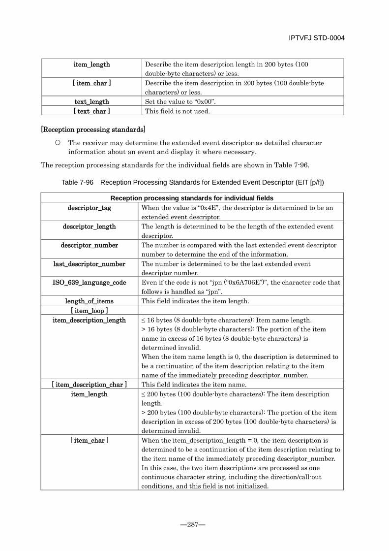
IPTVFJ STD-0004
—287—
item_length Describe the item description length in 200 bytes (100 double-byte characters) or less.
[ item_char ] Describe the item description in 200 bytes (100 double-byte characters) or less.
text_length Set the value to “0x00”. [ text_char ] This field is not used.
[Reception processing standards]
The receiver may determine the extended event descriptor as detailed character information about an event and display it where necessary.
The reception processing standards for the individual fields are shown in Table 7-96.
Table 7-96 Reception Processing Standards for Extended Event Descriptor (EIT [p/f])
Reception processing standards for individual fields descriptor_tag When the value is “0x4E”, the descriptor is determined to be an
extended event descriptor. descriptor_length The length is determined to be the length of the extended event
descriptor. descriptor_number The number is compared with the last extended event descriptor
number to determine the end of the information. last_descriptor_number The number is determined to be the last extended event
descriptor number. ISO_639_language_code Even if the code is not “jpn (“0x6A706E”)”, the character code that
follows is handled as “jpn”. length_of_items This field indicates the item length.
[ item_loop ] item_description_length ≤ 16 bytes (8 double-byte characters): Item name length.
> 16 bytes (8 double-byte characters): The portion of the item name in excess of 16 bytes (8 double-byte characters) is determined invalid. When the item name length is 0, the description is determined to be a continuation of the item description relating to the item name of the immediately preceding descriptor_number.
[ item_description_char ] This field indicates the item name. item_length ≤ 200 bytes (100 double-byte characters): The item description
length. > 200 bytes (100 double-byte characters): The portion of the item description in excess of 200 bytes (100 double-byte characters) is determined invalid.
[ item_char ] When the item_description_length = 0, the item description is determined to be a continuation of the item description relating to the item name of the immediately preceding descriptor_number. In this case, the two item descriptions are processed as one continuous character string, including the direction/call-out conditions, and this field is not initialized.
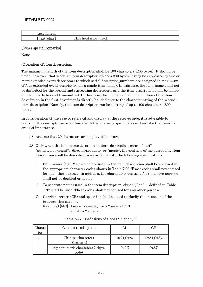
IPTVFJ STD-0004
-288-
text_length [ text_char ] This field is not used.
[Other special remarks]
None
(Operation of item description)
The maximum length of the item description shall be 100 characters (200 bytes). It should be noted, however, that when an item description exceeds 200 bytes, it may be expressed by two or more extended event descriptors to which serial descriptor_numbers are assigned (a maximum of four extended event descriptors for a single item name). In this case, the item name shall not be described for the second and succeeding descriptors, and the item description shall be simply divided into bytes and transmitted. In this case, the indication/callout condition of the item description in the first descriptor is directly handed over to the character string of the second item description. Namely, the item description can be a string of up to 400 characters (800 bytes).
In consideration of the ease of retrieval and display at the receiver side, it is advisable to transmit the descriptor in accordance with the following specifications. Describe the items in order of importance.
(1) Assume that 20 characters are displayed in a row.
(2) Only when the item name described in item_description_char is “cast”, “author/playwright”, “director/producer” or “music”, the contents of the succeeding item description shall be described in accordance with the following specifications.
Item names (e.g., MC) which are used in the item description shall be enclosed in the appropriate character codes shown in Table 7-98. Those codes shall not be used for any other purpose. In addition, the character codes used for the above purpose shall not be doubled or nested.
To separate names used in the item description, either ‘, ’ or ‘、’ defined in Table 7-97 shall be used. These codes shall not be used for any other purpose.
Carriage return (CR) and space (□) shall be used to clarify the intention of the broadcasting station. Example) [MC] Hanako Yamada, Taro Yamada (CR) □□□ Jiro Yamada
Table 7-97 Definitions of Codes “, ” and “、”
Character
Character code group GL GR
, Chinese characters (Section 1)
0x21,0x24 0xA1,0xA4
Alphanumeric characters (1-byte code)
0x2C 0xAC
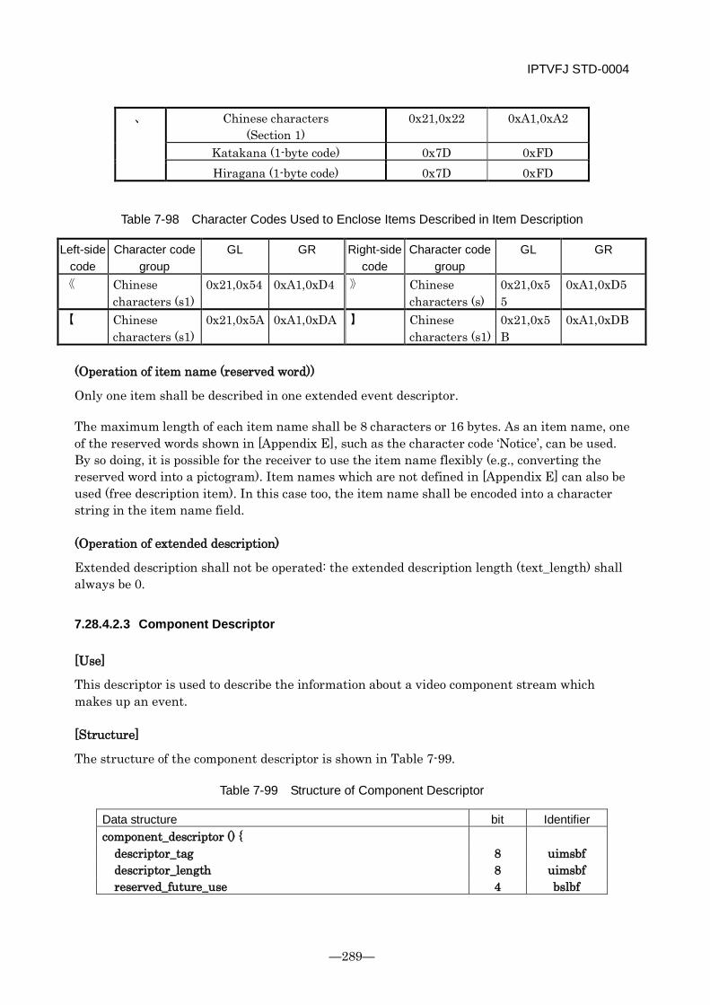
IPTVFJ STD-0004
—289—
、 Chinese characters (Section 1)
0x21,0x22 0xA1,0xA2
Katakana (1-byte code) 0x7D 0xFD Hiragana (1-byte code) 0x7D 0xFD
Table 7-98 Character Codes Used to Enclose Items Described in Item Description
Left-side code
Character code group
GL GR Right-side code
Character code group
GL GR
《 Chinese characters (s1)
0x21,0x54 0xA1,0xD4 》 Chinese characters (s)
0x21,0x55
0xA1,0xD5
【 Chinese characters (s1)
0x21,0x5A 0xA1,0xDA 】 Chinese characters (s1)
0x21,0x5B
0xA1,0xDB
(Operation of item name (reserved word))
Only one item shall be described in one extended event descriptor.
The maximum length of each item name shall be 8 characters or 16 bytes. As an item name, one of the reserved words shown in [Appendix E], such as the character code ‘Notice’, can be used. By so doing, it is possible for the receiver to use the item name flexibly (e.g., converting the reserved word into a pictogram). Item names which are not defined in [Appendix E] can also be used (free description item). In this case too, the item name shall be encoded into a character string in the item name field.
(Operation of extended description)
Extended description shall not be operated: the extended description length (text_length) shall always be 0.
7.28.4.2.3 Component Descriptor
[Use]
This descriptor is used to describe the information about a video component stream which makes up an event.
[Structure]
The structure of the component descriptor is shown in Table 7-99.
Table 7-99 Structure of Component Descriptor
Data structure bit Identifier component_descriptor () {
descriptor_tag 8 uimsbf descriptor_length 8 uimsbf reserved_future_use 4 bslbf
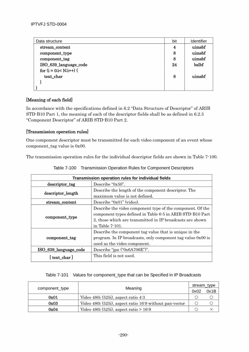
IPTVFJ STD-0004
-290-
Data structure bit Identifier stream_content 4 uimsbf component_type 8 uimsbf component_tag 8 uimsbf ISO_639_language_code 24 bslbf for (i = 0;i< N;i++) {
text_char 8 uimsbf }
}
[Meaning of each field]
In accordance with the specifications defined in 6.2 “Data Structure of Descriptor” of ARIB STD-B10 Part 1, the meaning of each of the descriptor fields shall be as defined in 6.2.3 “Component Descriptor” of ARIB STD-B10 Part 2.
[Transmission operation rules]
One component descriptor must be transmitted for each video component of an event whose component_tag value is 0x00.
The transmission operation rules for the individual descriptor fields are shown in Table 7-100.
Table 7-100 Transmission Operation Rules for Component Descriptors
Transmission operation rules for individual fields descriptor_tag Describe “0x50”.
descriptor_length Describe the length of the component descriptor. The maximum value is not defined.
stream_content Describe “0x01” (video).
component_type
Describe the video component type of the component. Of the component types defined in Table 6-5 in ARIB STD-B10 Part 2, those which are transmitted in IP broadcasts are shown in Table 7-101.
component_tag Describe the component tag value that is unique in the program. In IP broadcasts, only component tag value 0x00 is used as the video component.
ISO_639_language_code Describe “jpn (“0x6A706E”)”.
[ text_char ] This field is not used.
Table 7-101 Values for component_type that can be Specified in IP Broadcasts
component_type Meaning stream_type 0x02 0x1B
0x01 Video 480i (525i), aspect ratio 4:3 0x03 Video 480i (525i), aspect ratio 16:9 without pan-vector 0x04 Video 480i (525i), aspect ratio > 16:9
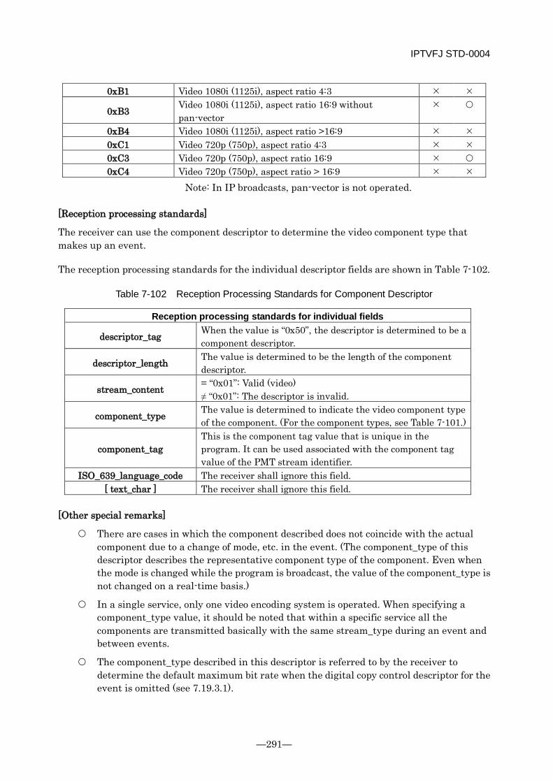
IPTVFJ STD-0004
—291—
0xB1 Video 1080i (1125i), aspect ratio 4:3
0xB3 Video 1080i (1125i), aspect ratio 16:9 without pan-vector
0xB4 Video 1080i (1125i), aspect ratio >16:9 0xC1 Video 720p (750p), aspect ratio 4:3 0xC3 Video 720p (750p), aspect ratio 16:9 0xC4 Video 720p (750p), aspect ratio > 16:9
Note: In IP broadcasts, pan-vector is not operated.
[Reception processing standards]
The receiver can use the component descriptor to determine the video component type that makes up an event.
The reception processing standards for the individual descriptor fields are shown in Table 7-102.
Table 7-102 Reception Processing Standards for Component Descriptor
Reception processing standards for individual fields
descriptor_tag When the value is “0x50”, the descriptor is determined to be a component descriptor.
descriptor_length The value is determined to be the length of the component descriptor.
stream_content = “0x01”: Valid (video) ≠ “0x01”: The descriptor is invalid.
component_type The value is determined to indicate the video component type of the component. (For the component types, see Table 7-101.)
component_tag This is the component tag value that is unique in the program. It can be used associated with the component tag value of the PMT stream identifier.
ISO_639_language_code The receiver shall ignore this field. [ text_char ] The receiver shall ignore this field.
[Other special remarks]
There are cases in which the component described does not coincide with the actual component due to a change of mode, etc. in the event. (The component_type of this descriptor describes the representative component type of the component. Even when the mode is changed while the program is broadcast, the value of the component_type is not changed on a real-time basis.)
In a single service, only one video encoding system is operated. When specifying a component_type value, it should be noted that within a specific service all the components are transmitted basically with the same stream_type during an event and between events.
The component_type described in this descriptor is referred to by the receiver to determine the default maximum bit rate when the digital copy control descriptor for the event is omitted (see 7.19.3.1).
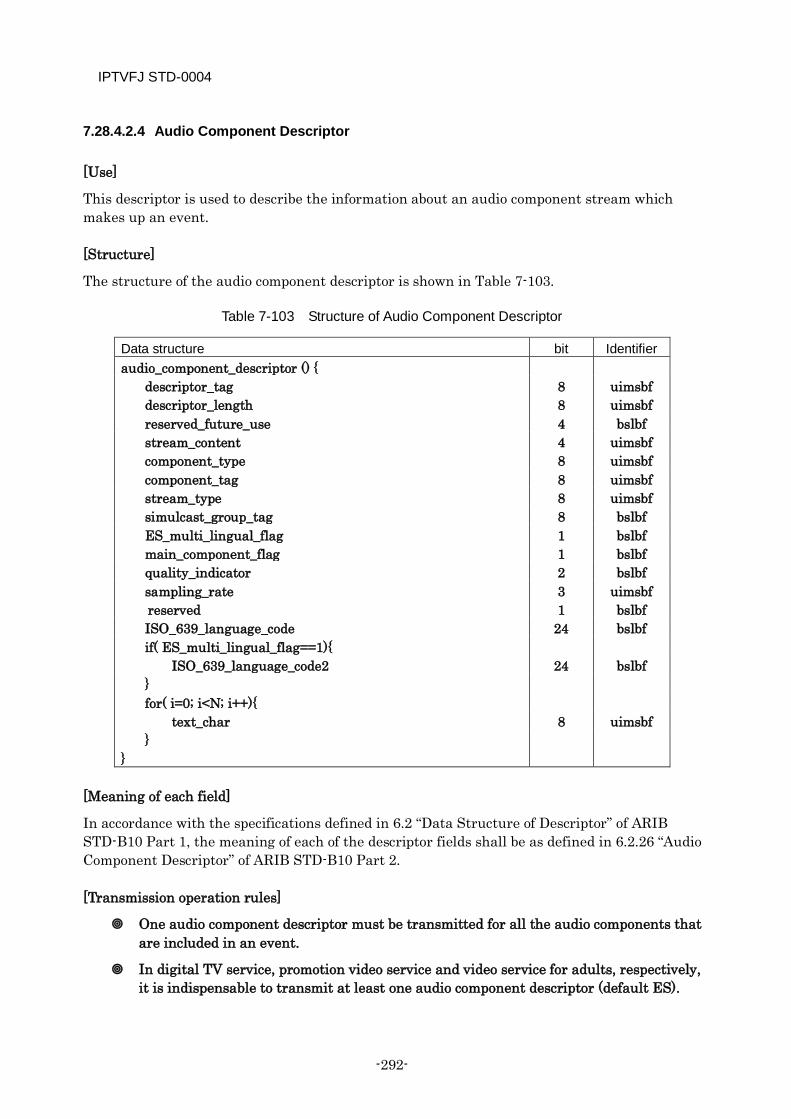
IPTVFJ STD-0004
-292-
7.28.4.2.4 Audio Component Descriptor
[Use]
This descriptor is used to describe the information about an audio component stream which makes up an event.
[Structure]
The structure of the audio component descriptor is shown in Table 7-103.
Table 7-103 Structure of Audio Component Descriptor
Data structure bit Identifier audio_component_descriptor () {
descriptor_tag 8 uimsbf descriptor_length 8 uimsbf reserved_future_use 4 bslbf stream_content 4 uimsbf component_type 8 uimsbf component_tag 8 uimsbf stream_type 8 uimsbf simulcast_group_tag 8 bslbf ES_multi_lingual_flag 1 bslbf main_component_flag 1 bslbf quality_indicator 2 bslbf sampling_rate 3 uimsbf
reserved 1 bslbf ISO_639_language_code 24 bslbf if( ES_multi_lingual_flag==1){
ISO_639_language_code2 24 bslbf } for( i=0; i<N; i++){ text_char 8 uimsbf }
}
[Meaning of each field]
In accordance with the specifications defined in 6.2 “Data Structure of Descriptor” of ARIB STD-B10 Part 1, the meaning of each of the descriptor fields shall be as defined in 6.2.26 “Audio Component Descriptor” of ARIB STD-B10 Part 2.
[Transmission operation rules]
One audio component descriptor must be transmitted for all the audio components that are included in an event.
In digital TV service, promotion video service and video service for adults, respectively, it is indispensable to transmit at least one audio component descriptor (default ES).
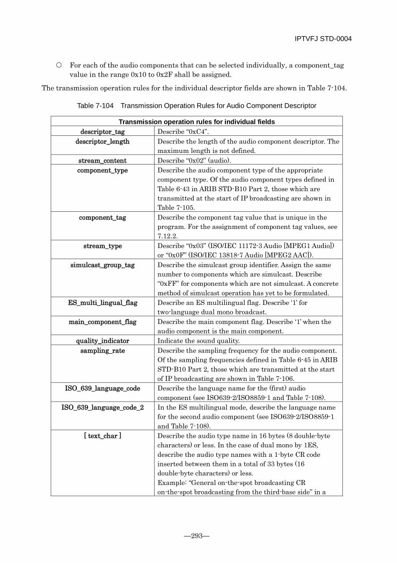
IPTVFJ STD-0004
—293—
For each of the audio components that can be selected individually, a component_tag value in the range 0x10 to 0x2F shall be assigned.
The transmission operation rules for the individual descriptor fields are shown in Table 7-104.
Table 7-104 Transmission Operation Rules for Audio Component Descriptor
Transmission operation rules for individual fields descriptor_tag Describe “0xC4”.
descriptor_length Describe the length of the audio component descriptor. The maximum length is not defined.
stream_content Describe “0x02” (audio). component_type Describe the audio component type of the appropriate
component type. Of the audio component types defined in Table 6-43 in ARIB STD-B10 Part 2, those which are transmitted at the start of IP broadcasting are shown in Table 7-105.
component_tag Describe the component tag value that is unique in the program. For the assignment of component tag values, see 7.12.2.
stream_type Describe “0x03” (ISO/IEC 11172-3 Audio [MPEG1 Audio]) or “0x0F” (ISO/IEC 13818-7 Audio [MPEG2 AAC]).
simulcast_group_tag Describe the simulcast group identifier. Assign the same number to components which are simulcast. Describe “0xFF” for components which are not simulcast. A concrete method of simulcast operation has yet to be formulated.
ES_multi_lingual_flag Describe an ES multilingual flag. Describe ‘1’ for two-language dual mono broadcast.
main_component_flag Describe the main component flag. Describe ‘1’ when the audio component is the main component.
quality_indicator Indicate the sound quality. sampling_rate Describe the sampling frequency for the audio component.
Of the sampling frequencies defined in Table 6-45 in ARIB STD-B10 Part 2, those which are transmitted at the start of IP broadcasting are shown in Table 7-106.
ISO_639_language_code Describe the language name for the (first) audio component (see ISO639-2/ISO8859-1 and Table 7-108).
ISO_639_language_code_2 In the ES multilingual mode, describe the language name for the second audio component (see ISO639-2/ISO8859-1 and Table 7-108).
[ text_char ] Describe the audio type name in 16 bytes (8 double-byte characters) or less. In the case of dual mono by 1ES, describe the audio type names with a 1-byte CR code inserted between them in a total of 33 bytes (16 double-byte characters) or less. Example: “General on-the-spot broadcasting CR on-the-spot broadcasting from the third-base side” in a

IPTVFJ STD-0004
-294-
relay broadcast of baseball game. When the above description is the default character string, this field may be omitted. For the default character string, see 4.4.1 of the Receiver Specifications of ARIB TR-B15 Volume 2.
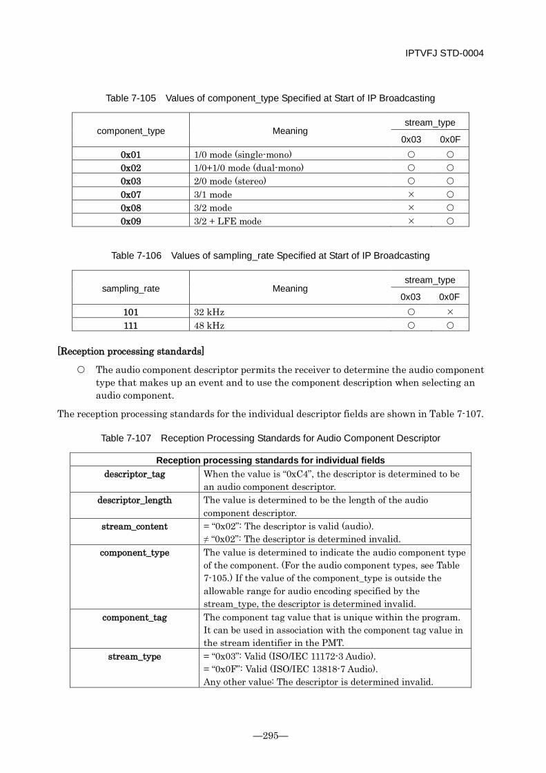
IPTVFJ STD-0004
—295—
Table 7-105 Values of component_type Specified at Start of IP Broadcasting
component_type Meaning stream_type
0x03 0x0F 0x01 1/0 mode (single-mono) 0x02 1/0+1/0 mode (dual-mono) 0x03 2/0 mode (stereo) 0x07 3/1 mode 0x08 3/2 mode 0x09 3/2 + LFE mode
Table 7-106 Values of sampling_rate Specified at Start of IP Broadcasting
sampling_rate Meaning stream_type
0x03 0x0F 101 32 kHz 111 48 kHz
[Reception processing standards]
The audio component descriptor permits the receiver to determine the audio component type that makes up an event and to use the component description when selecting an audio component.
The reception processing standards for the individual descriptor fields are shown in Table 7-107.
Table 7-107 Reception Processing Standards for Audio Component Descriptor
Reception processing standards for individual fields descriptor_tag When the value is “0xC4”, the descriptor is determined to be
an audio component descriptor. descriptor_length The value is determined to be the length of the audio
component descriptor. stream_content = “0x02”: The descriptor is valid (audio).
≠ “0x02”: The descriptor is determined invalid. component_type The value is determined to indicate the audio component type
of the component. (For the audio component types, see Table 7-105.) If the value of the component_type is outside the allowable range for audio encoding specified by the stream_type, the descriptor is determined invalid.
component_tag The component tag value that is unique within the program. It can be used in association with the component tag value in the stream identifier in the PMT.
stream_type = “0x03”: Valid (ISO/IEC 11172-3 Audio). = “0x0F”: Valid (ISO/IEC 13818-7 Audio). Any other value: The descriptor is determined invalid.
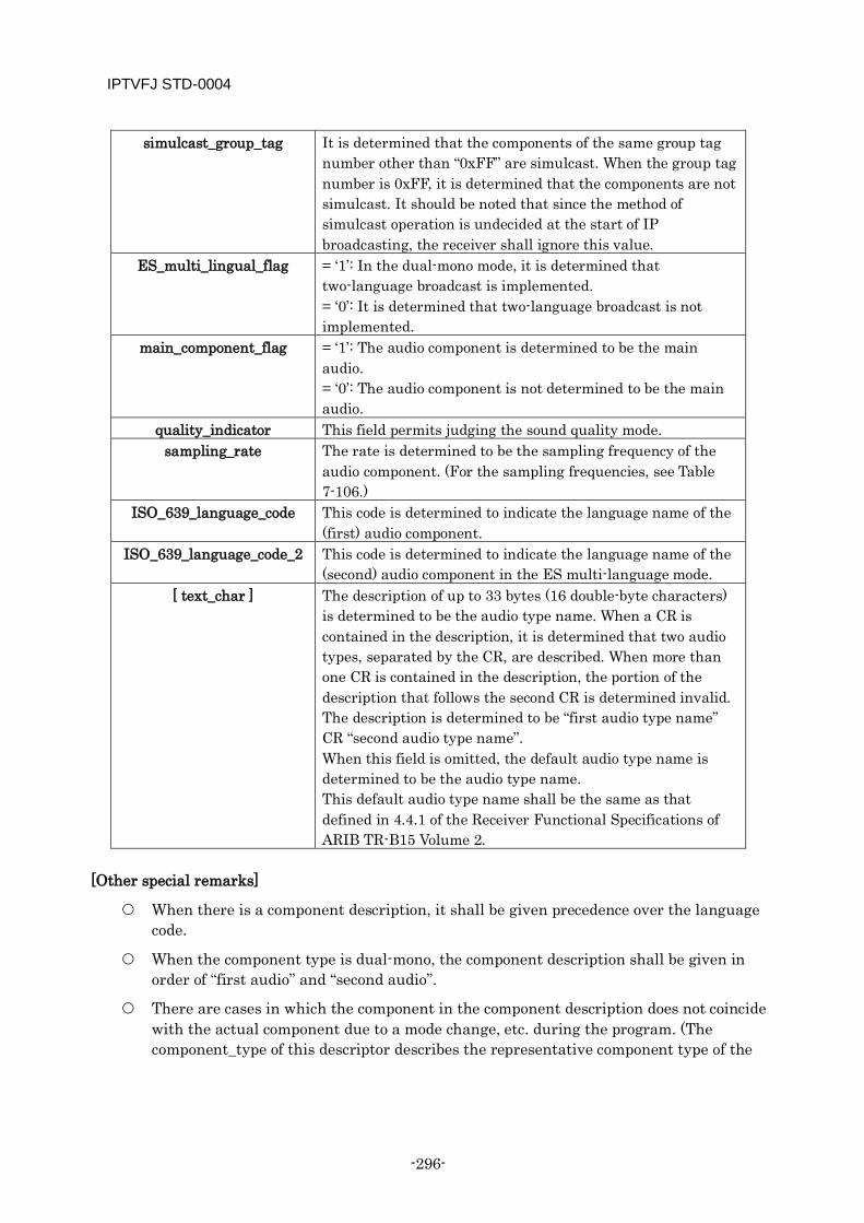
IPTVFJ STD-0004
-296-
simulcast_group_tag It is determined that the components of the same group tag number other than “0xFF” are simulcast. When the group tag number is 0xFF, it is determined that the components are not simulcast. It should be noted that since the method of simulcast operation is undecided at the start of IP broadcasting, the receiver shall ignore this value.
ES_multi_lingual_flag = ‘1’: In the dual-mono mode, it is determined that two-language broadcast is implemented. = ‘0’: It is determined that two-language broadcast is not implemented.
main_component_flag = ‘1’: The audio component is determined to be the main audio. = ‘0’: The audio component is not determined to be the main audio.
quality_indicator This field permits judging the sound quality mode. sampling_rate The rate is determined to be the sampling frequency of the
audio component. (For the sampling frequencies, see Table 7-106.)
ISO_639_language_code This code is determined to indicate the language name of the (first) audio component.
ISO_639_language_code_2 This code is determined to indicate the language name of the (second) audio component in the ES multi-language mode.
[ text_char ] The description of up to 33 bytes (16 double-byte characters) is determined to be the audio type name. When a CR is contained in the description, it is determined that two audio types, separated by the CR, are described. When more than one CR is contained in the description, the portion of the description that follows the second CR is determined invalid. The description is determined to be “first audio type name” CR “second audio type name”. When this field is omitted, the default audio type name is determined to be the audio type name. This default audio type name shall be the same as that defined in 4.4.1 of the Receiver Functional Specifications of ARIB TR-B15 Volume 2.
[Other special remarks]
When there is a component description, it shall be given precedence over the language code.
When the component type is dual-mono, the component description shall be given in order of “first audio” and “second audio”.
There are cases in which the component in the component description does not coincide with the actual component due to a mode change, etc. during the program. (The component_type of this descriptor describes the representative component type of the
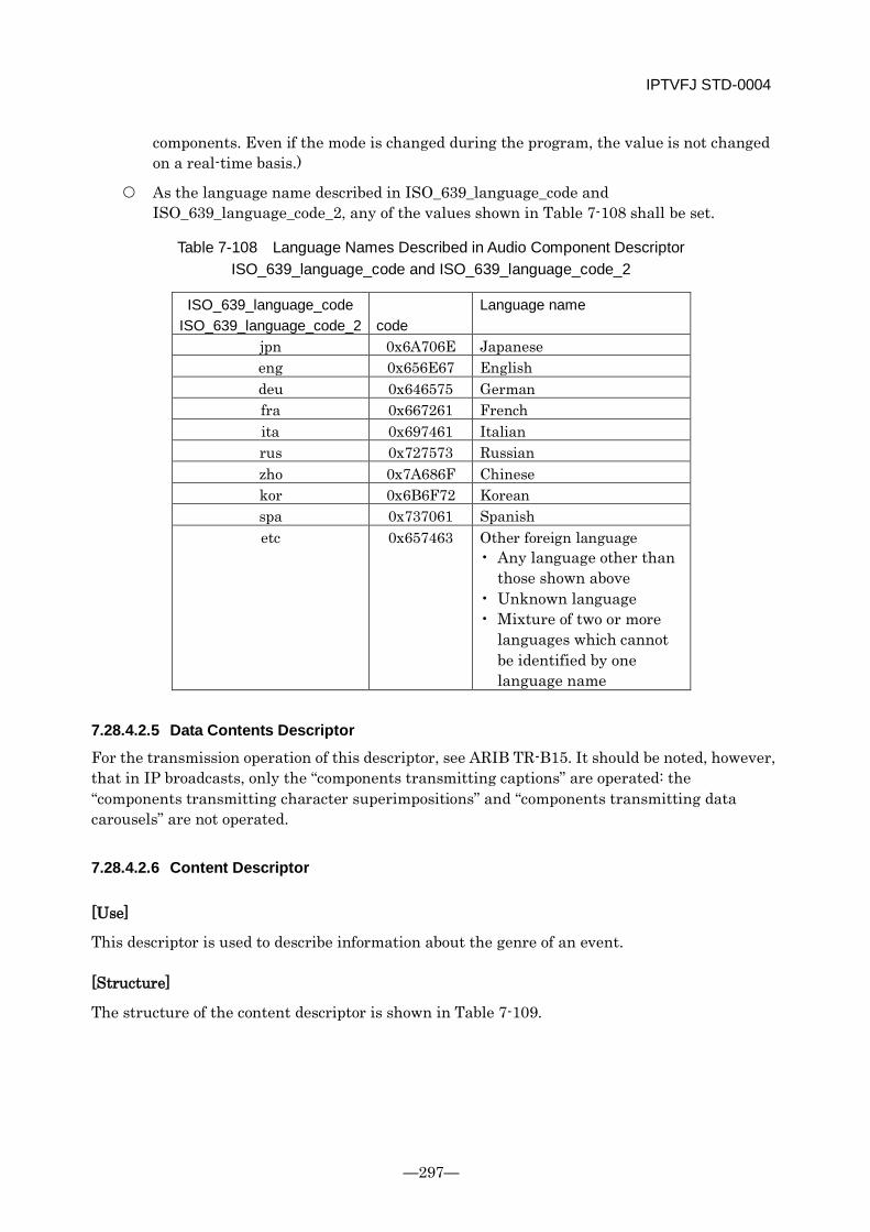
IPTVFJ STD-0004
—297—
components. Even if the mode is changed during the program, the value is not changed on a real-time basis.)
As the language name described in ISO_639_language_code and ISO_639_language_code_2, any of the values shown in Table 7-108 shall be set.
Table 7-108 Language Names Described in Audio Component Descriptor ISO_639_language_code and ISO_639_language_code_2
ISO_639_language_code ISO_639_language_code_2
code
Language name
jpn 0x6A706E Japanese eng 0x656E67 English deu 0x646575 German fra 0x667261 French ita 0x697461 Italian rus 0x727573 Russian zho 0x7A686F Chinese kor 0x6B6F72 Korean spa 0x737061 Spanish etc 0x657463 Other foreign language
• Any language other than those shown above
• Unknown language • Mixture of two or more
languages which cannot be identified by one language name
7.28.4.2.5 Data Contents Descriptor
For the transmission operation of this descriptor, see ARIB TR-B15. It should be noted, however, that in IP broadcasts, only the “components transmitting captions” are operated: the “components transmitting character superimpositions” and “components transmitting data carousels” are not operated.
7.28.4.2.6 Content Descriptor
[Use]
This descriptor is used to describe information about the genre of an event.
[Structure]
The structure of the content descriptor is shown in Table 7-109.
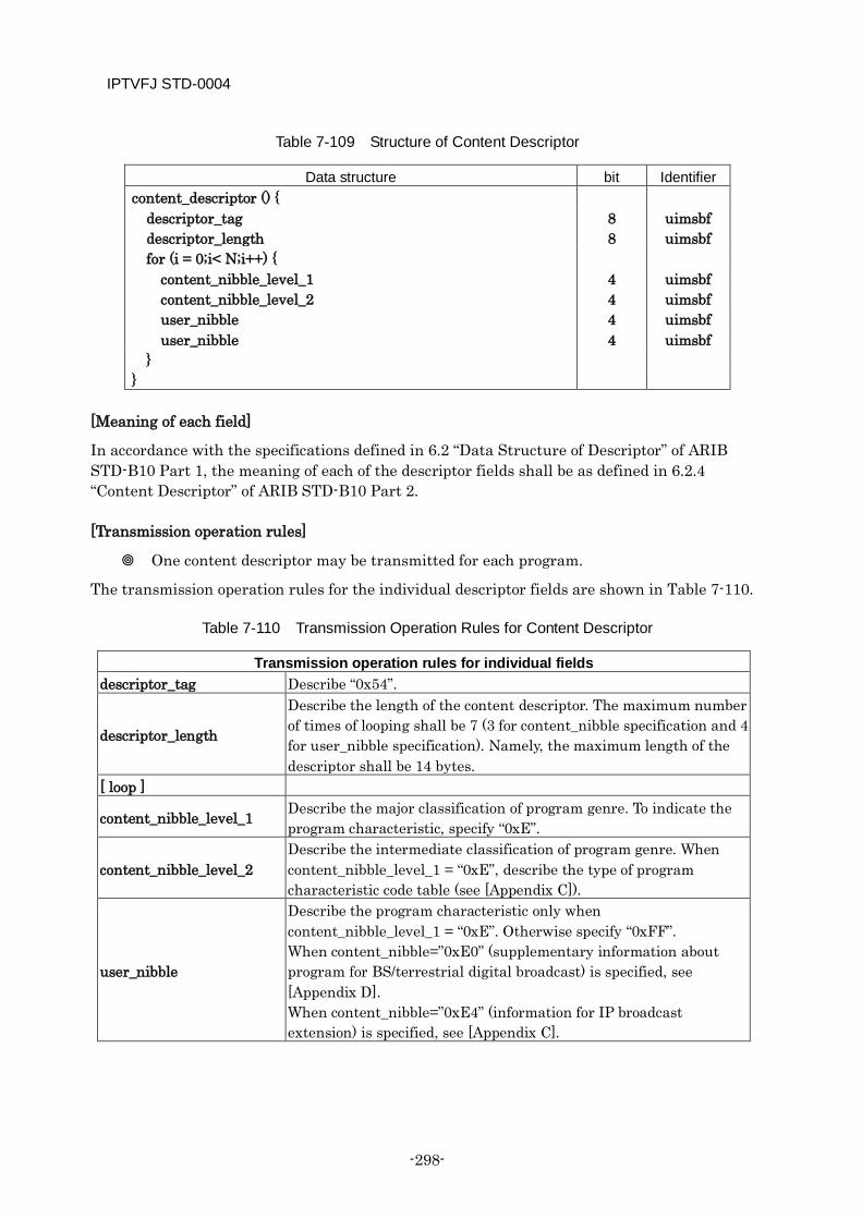
IPTVFJ STD-0004
-298-
Table 7-109 Structure of Content Descriptor
Data structure bit Identifier content_descriptor () {
descriptor_tag 8 uimsbf descriptor_length 8 uimsbf for (i = 0;i< N;i++) {
content_nibble_level_1 4 uimsbf content_nibble_level_2 4 uimsbf user_nibble 4 uimsbf user_nibble 4 uimsbf
} }
[Meaning of each field]
In accordance with the specifications defined in 6.2 “Data Structure of Descriptor” of ARIB STD-B10 Part 1, the meaning of each of the descriptor fields shall be as defined in 6.2.4 “Content Descriptor” of ARIB STD-B10 Part 2.
[Transmission operation rules]
One content descriptor may be transmitted for each program.
The transmission operation rules for the individual descriptor fields are shown in Table 7-110.
Table 7-110 Transmission Operation Rules for Content Descriptor
Transmission operation rules for individual fields descriptor_tag Describe “0x54”.
descriptor_length
Describe the length of the content descriptor. The maximum number of times of looping shall be 7 (3 for content_nibble specification and 4 for user_nibble specification). Namely, the maximum length of the descriptor shall be 14 bytes.
[ loop ]
content_nibble_level_1 Describe the major classification of program genre. To indicate the program characteristic, specify “0xE”.
content_nibble_level_2 Describe the intermediate classification of program genre. When content_nibble_level_1 = “0xE”, describe the type of program characteristic code table (see [Appendix C]).
user_nibble
Describe the program characteristic only when content_nibble_level_1 = “0xE”. Otherwise specify “0xFF”. When content_nibble=”0xE0” (supplementary information about program for BS/terrestrial digital broadcast) is specified, see [Appendix D]. When content_nibble=”0xE4” (information for IP broadcast extension) is specified, see [Appendix C].
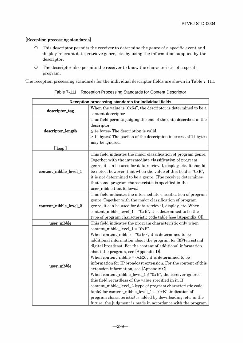
IPTVFJ STD-0004
—299—
[Reception processing standards]
This descriptor permits the receiver to determine the genre of a specific event and display relevant data, retrieve genre, etc. by using the information supplied by the descriptor.
The descriptor also permits the receiver to know the characteristic of a specific program.
The reception processing standards for the individual descriptor fields are shown in Table 7-111.
Table 7-111 Reception Processing Standards for Content Descriptor
Reception processing standards for individual fields
descriptor_tag When the value is “0x54”, the descriptor is determined to be a content descriptor.
descriptor_length
This field permits judging the end of the data described in the descriptor. ≤ 14 bytes: The description is valid. > 14 bytes: The portion of the description in excess of 14 bytes may be ignored.
[ loop ]
content_nibble_level_1
This field indicates the major classification of program genre. Together with the intermediate classification of program genre, it can be used for data retrieval, display, etc. It should be noted, however, that when the value of this field is “0xE”, it is not determined to be a genre. (The receiver determines that some program characteristic is specified in the user_nibble that follows.)
content_nibble_level_2
This field indicates the intermediate classification of program genre. Together with the major classification of program genre, it can be used for data retrieval, display, etc. When content_nibble_level_1 = “0xE”, it is determined to be the type of program characteristic code table (see [Appendix C]).
user_nibble This field indicates the program characteristic only when content_nibble_level_1 = “0xE”. When content_nibble = “0xE0”, it is determined to be additional information about the program for BS/terrestrial digital broadcast. For the content of additional information about the program, see [Appendix D]. When content_nibble = 0xEX”, it is determined to be information for IP broadcast extension. For the content of this extension information, see [Appendix C]. When content_nibble_level_1 ≠ “0xE”, the receiver ignores this field regardless of the value specified in it. If content_nibble_level_2 (type of program characteristic code table) for content_nibble_level_1 = “0xE” (indication of program characteristic) is added by downloading, etc. in the future, the judgment is made in accordance with the program
user_nibble

IPTVFJ STD-0004
-300-
characteristic code table that is added.
[Other special remarks]
For the program genre of an event which is broadcast in a service whose service_type is “0x80” (video service for adults), user_nibble_level_1 = 0x3 must be described and operated with content_nibble_level_1= “0xE” and content_nibble_level_2=”0x4”.
(Detailed operation of content descriptor)
The content descriptor indicates the genre information about a specific event by content_nibble_level_1 (major classification) and content_nibble_level_2 (intermediate classification).
The maximum number of genre code loops shall be 7 (3 for content_nibble specification and 4 for user_nibble specification).
The genre code table to be used at the start of IP broadcasting is shown in [Appendix C]. There is the possibility that this genre code table will be extended by downloading, etc. in the future. Even in that case, the contents of genres (contents of descriptions) that have already been defined in [Appendix C] shall not be changed or deleted. (The existing codes shall not be changed either.) Namely, only the columns of the genre code table that are now left blank shall be used to describe extensions as required.
When a new genre code is added, the receiver that grasps the genre names for content_nibble_level_1 might not grasp the genre names for content_nibble_level_2. Even in that case, the receiver is allowed to determine that only the genres specified by content_nibble_level_1 (major classification) are valid.
In the table in [Appendix C], the item defined as “Other” has two different meanings in terms of both the major classification and intermediate classification. One is that the program does not belong to any of the specified genres: it belongs to some unspecified genre. The other is that the program belongs to more than one genre and it is impossible to definitely specify the genre to which it belongs.
In IP broadcasts, the user_nibble shall be operated only to specify additional information about programs for BS/terrestrial digital broadcast and extended information for IP broadcast shown in [Appendix D]. In this case, “0xE0” or “0xEX” must be specified for the content_nibble.
When content_nibble_level_1 is other than “0xE”, “0xF” shall be specified for both user_nibbles. Namely, it is not allowed to define both a genre and a program characteristic in a single loop.
When content_nibble_level_1 is “0xE”, it indicates the major classification for identification by content_nibble_level_2 of the type of program characteristic code table for encoding in the user_nibble area that follows. Therefore, it is not used as a genre name and the receiver must exclude the value from the objects of retrieval in the genre retrieval function, etc.
Concerning user_nibble, there is the possibility that an entirely new program characteristic code table will be added in the future. In that case, a classification for

IPTVFJ STD-0004
—301—
identification of the new code table type will be added to content_nibble as well. In IP broadcasts, therefore, when content_nibble_level_1 = “0xE”, any value other than “0x0” or “0x4” must not be specified for content_nibble_level_2 (the receiver determines it invalid). Even so, there is the possibility that a new code table will be added by downloading, etc. in the future.
7.28.4.2.7 Digital Copy Control Descriptor
[Use]
This descriptor is used to describe the digital copy/analog copy control information or the maximum transmission rate, for a specific event.
[Structure]
The structure of the digital copy control descriptor is shown in Table 7-112.
Table 7-112 Structure of Digital Copy Control Descriptor
Data structure bit Identifier digital_copy_control_descriptor () {
descriptor_tag 8 uimsbf descriptor_length 8 uimsbf digital_recording_control_data 2 bslbf maximum_bit_rate_flag 1 bslbf component_control_flag 1 bslbf copy_control_type if(copy_control_type==01){ APS_control_data } else{ reserved_future_use }
2 2 2
bslbf
bslbf
bslbf
if( maximum_bit_rate_flag == 1 ) { maximum_bit_rate 8 uimsbf
} if( component_control_flag ==1 ){ component_control_length 8 uimsbf for(j=0;j<N;j++){ component_tag 8 uimsbf digital_recording_control_data 2 bslbf maximum_bitrate_flag 1 bslbf reserved_future_use 1 bslbf copy_control_type if(copy_control_type==01) { APS_control_data } else{
2 2
bslbf
bslbf
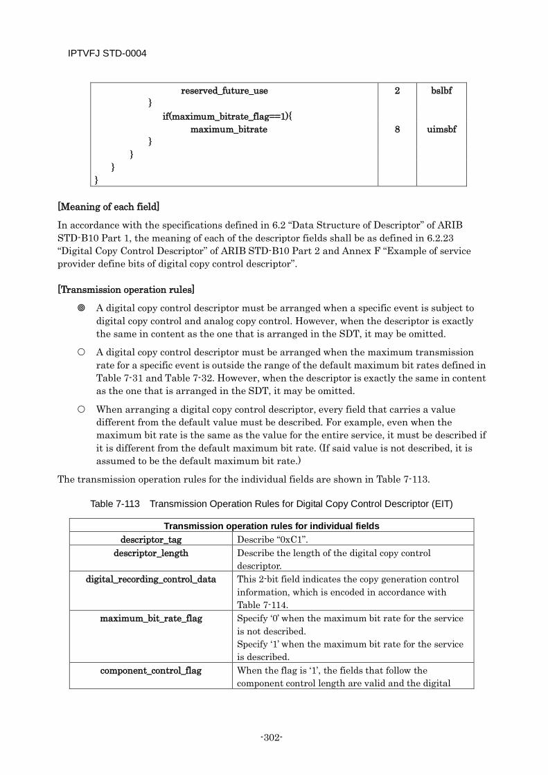
IPTVFJ STD-0004
-302-
reserved_future_use }
2 bslbf
if(maximum_bitrate_flag==1){ maximum_bitrate 8 uimsbf } } }
}
[Meaning of each field]
In accordance with the specifications defined in 6.2 “Data Structure of Descriptor” of ARIB STD-B10 Part 1, the meaning of each of the descriptor fields shall be as defined in 6.2.23 “Digital Copy Control Descriptor” of ARIB STD-B10 Part 2 and Annex F “Example of service provider define bits of digital copy control descriptor”.
[Transmission operation rules]
A digital copy control descriptor must be arranged when a specific event is subject to digital copy control and analog copy control. However, when the descriptor is exactly the same in content as the one that is arranged in the SDT, it may be omitted.
A digital copy control descriptor must be arranged when the maximum transmission rate for a specific event is outside the range of the default maximum bit rates defined in Table 7-31 and Table 7-32. However, when the descriptor is exactly the same in content as the one that is arranged in the SDT, it may be omitted.
When arranging a digital copy control descriptor, every field that carries a value different from the default value must be described. For example, even when the maximum bit rate is the same as the value for the entire service, it must be described if it is different from the default maximum bit rate. (If said value is not described, it is assumed to be the default maximum bit rate.)
The transmission operation rules for the individual fields are shown in Table 7-113.
Table 7-113 Transmission Operation Rules for Digital Copy Control Descriptor (EIT)
Transmission operation rules for individual fields descriptor_tag Describe “0xC1”.
descriptor_length Describe the length of the digital copy control descriptor.
digital_recording_control_data This 2-bit field indicates the copy generation control information, which is encoded in accordance with Table 7-114.
maximum_bit_rate_flag Specify ‘0’ when the maximum bit rate for the service is not described. Specify ‘1’ when the maximum bit rate for the service is described.
component_control_flag When the flag is ‘1’, the fields that follow the component control length are valid and the digital
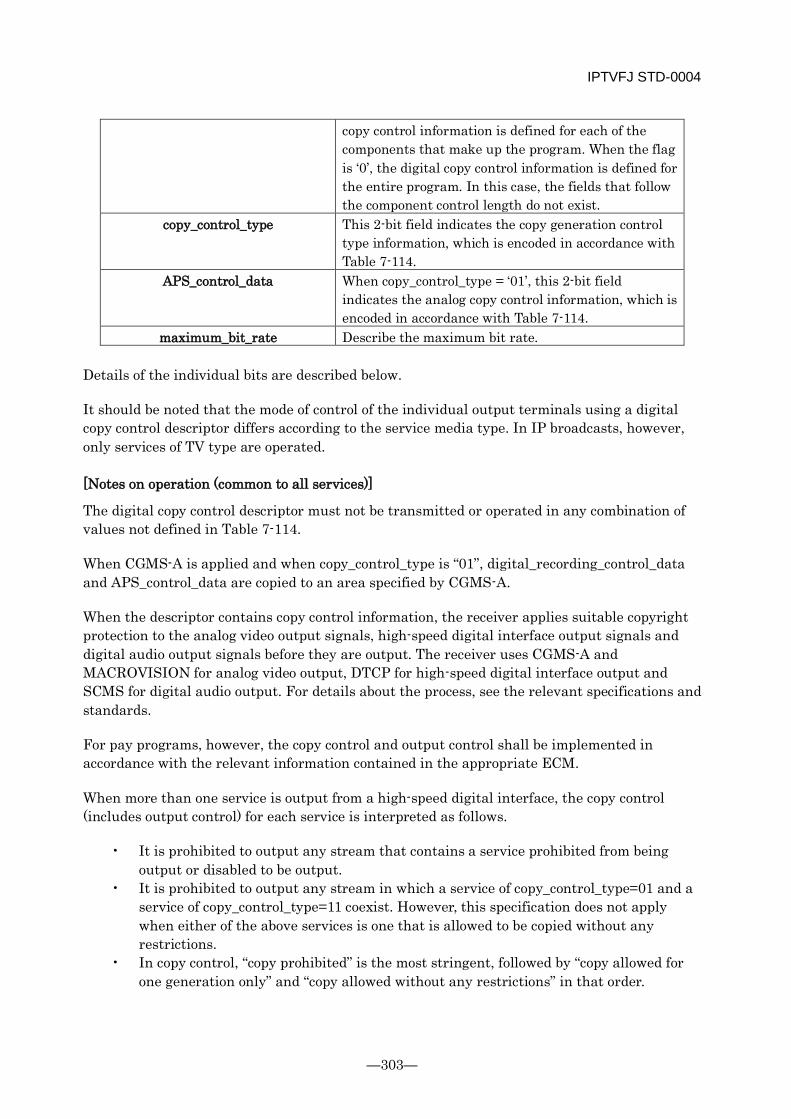
IPTVFJ STD-0004
—303—
copy control information is defined for each of the components that make up the program. When the flag is ‘0’, the digital copy control information is defined for the entire program. In this case, the fields that follow the component control length do not exist.
copy_control_type This 2-bit field indicates the copy generation control type information, which is encoded in accordance with Table 7-114.
APS_control_data When copy_control_type = ‘01’, this 2-bit field indicates the analog copy control information, which is encoded in accordance with Table 7-114.
maximum_bit_rate Describe the maximum bit rate. Details of the individual bits are described below.
It should be noted that the mode of control of the individual output terminals using a digital copy control descriptor differs according to the service media type. In IP broadcasts, however, only services of TV type are operated.
[Notes on operation (common to all services)]
The digital copy control descriptor must not be transmitted or operated in any combination of values not defined in Table 7-114.
When CGMS-A is applied and when copy_control_type is “01”, digital_recording_control_data and APS_control_data are copied to an area specified by CGMS-A.
When the descriptor contains copy control information, the receiver applies suitable copyright protection to the analog video output signals, high-speed digital interface output signals and digital audio output signals before they are output. The receiver uses CGMS-A and MACROVISION for analog video output, DTCP for high-speed digital interface output and SCMS for digital audio output. For details about the process, see the relevant specifications and standards.
For pay programs, however, the copy control and output control shall be implemented in accordance with the relevant information contained in the appropriate ECM.
When more than one service is output from a high-speed digital interface, the copy control (includes output control) for each service is interpreted as follows.
• It is prohibited to output any stream that contains a service prohibited from being output or disabled to be output.
• It is prohibited to output any stream in which a service of copy_control_type=01 and a service of copy_control_type=11 coexist. However, this specification does not apply when either of the above services is one that is allowed to be copied without any restrictions.
• In copy control, “copy prohibited” is the most stringent, followed by “copy allowed for one generation only” and “copy allowed without any restrictions” in that order.
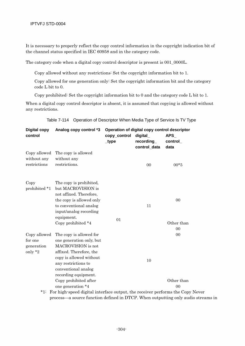
IPTVFJ STD-0004
-304-
It is necessary to properly reflect the copy control information in the copyright indication bit of the channel status specified in IEC 60958 and in the category code.
The category code when a digital copy control descriptor is present is 001_0000L.
Copy allowed without any restrictions: Set the copyright information bit to 1.
Copy allowed for one generation only: Set the copyright information bit and the category code L bit to 0.
Copy prohibited: Set the copyright information bit to 0 and the category code L bit to 1.
When a digital copy control descriptor is absent, it is assumed that copying is allowed without any restrictions.
Table 7-114 Operation of Descriptor When Media Type of Service Is TV Type
Digital copy control
Analog copy control *3 Operation of digital copy control descriptor copy_control_type
digital_ recording_ control_data
APS_ control_ data
Copy allowed without any restrictions
The copy is allowed without any restrictions.
01
00 00*5
Copy prohibited *1
The copy is prohibited, but MACROVISION is not affixed. Therefore, the copy is allowed only to conventional analog input/analog recording equipment.
11 00
Copy prohibited *4 Other than 00
Copy allowed for one generation only *2
The copy is allowed for one generation only, but MACROVISION is not affixed. Therefore, the copy is allowed without any restrictions to conventional analog recording equipment.
10
00
Copy prohibited after one generation *4
Other than 00
*1: For high-speed digital interface output, the receiver performs the Copy Never process—a source function defined in DTCP. When outputting only audio streams in
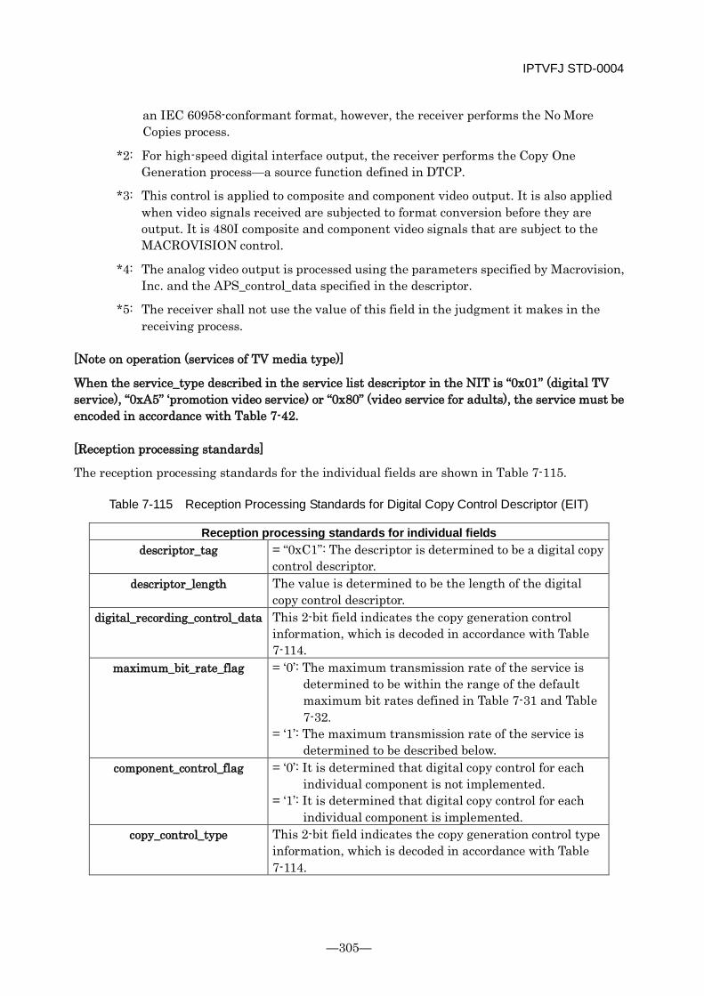
IPTVFJ STD-0004
—305—
an IEC 60958-conformant format, however, the receiver performs the No More Copies process.
*2: For high-speed digital interface output, the receiver performs the Copy One Generation process—a source function defined in DTCP.
*3: This control is applied to composite and component video output. It is also applied when video signals received are subjected to format conversion before they are output. It is 480I composite and component video signals that are subject to the MACROVISION control.
*4: The analog video output is processed using the parameters specified by Macrovision, Inc. and the APS_control_data specified in the descriptor.
*5: The receiver shall not use the value of this field in the judgment it makes in the receiving process.
[Note on operation (services of TV media type)]
When the service_type described in the service list descriptor in the NIT is “0x01” (digital TV service), “0xA5” ‘promotion video service) or “0x80” (video service for adults), the service must be encoded in accordance with Table 7-42.
[Reception processing standards]
The reception processing standards for the individual fields are shown in Table 7-115.
Table 7-115 Reception Processing Standards for Digital Copy Control Descriptor (EIT)
Reception processing standards for individual fields descriptor_tag = “0xC1”: The descriptor is determined to be a digital copy
control descriptor. descriptor_length The value is determined to be the length of the digital
copy control descriptor. digital_recording_control_data This 2-bit field indicates the copy generation control
information, which is decoded in accordance with Table 7-114.
maximum_bit_rate_flag = ‘0’: The maximum transmission rate of the service is determined to be within the range of the default maximum bit rates defined in Table 7-31 and Table 7-32.
= ‘1’: The maximum transmission rate of the service is determined to be described below.
component_control_flag = ‘0’: It is determined that digital copy control for each individual component is not implemented.
= ‘1’: It is determined that digital copy control for each individual component is implemented.
copy_control_type This 2-bit field indicates the copy generation control type information, which is decoded in accordance with Table 7-114.
IPTVFJ STD-0004
-306-
maximum_bit_rate The value is determined to be the maximum transmission rate of the service.
[Other special remarks]
The copy control of analog output signals depends on an agreement between the broadcaster concerned and Macrovision, Inc., etc. Therefore, it is considered necessary to carefully discuss it in the future.
The reception processing to be performed in the following cases not defined in Table 7-114 is shown below.
□ Service of TV media type
When copy_control_type=00/10/11: Outputting analog video output signals, digital audio output signals and high-speed digital interface output signals is prohibited.
When copy_control_type = 01, digital_recording_control_data = 01: High-speed digital interface output signals are processed on the assumption that the EMI is “01”. The other output signals are processed on the assumption that copy_control_type=01 and digital_recording_control_data=11.
7.28.4.2.8 Parental Rate Descriptor
See ARIB TR-B15. It should be noted, however, that in IP broadcasts, the parental rate that can be set differs according to the service_type of a specific service channel (see 7.18.4).
7.28.4.2.9 Series Descriptor
See ARIB TR-B15. It should be noted, however, that the series_id is unique within the service_id.
7.28.5 Stuffing Table (ST)
7.28.5.1 Structure and Operation of ST See ARIB TR-B15.
7.28.6 Descriptor not Defined in Any Table
7.28.6.1 Stuffing Descriptor See ARIB TR-B15.
IPTVFJ STD-0004
—307—
[Appendix A] Operational Specifications on H.264/MPEG-4 AVC
These Specifications concern the transmission operation of the video encoding system defined in H.264/MPEG-4 AVC (ITU-T Rec. H.264/ISO/IEC 14496-10) that is supposed to be used in IP broadcasting service.
A.1 Outline of H.264/MPEG-4 AVC H.264/MPEG-4 AVC was co-developed by the VCEG of ITU-T and the MPEG of ISO/IEC as the next-generation moving picture compression system offering superior compression efficiency to MPEG-2 Video (ISO/IEC 13818-2), MPEG-4 Visual (ISO/IEC 14496-2), ITU-T H.263, etc. In 2005, it was standardized as ITU-T H.264/ISO/IEC 14496-10.
With the aim of offering higher picture quality than the conventional systems, H.264/MPEG-4 AVC has introduced various new component technologies as described below. It uses an integer-precision DCT for a 4 × 4 block which is smaller than the conventional 8 × 8 block. (With the profile, an 8 × 8 integer-precision DCT is also possible.) Concerning the I picture, the differential value obtained by intra prediction is subjected to DCT, which makes it possible to reduce the amount of encoding of I pictures. On the other hand, for time-based prediction, the number of reference frames in both the past and future directions has been increased and it has been made possible to change the block size adaptively, from a minimum of 4 × 4 to a maximum of 16 × 16. In addition, the precision of motion compensation has been improved to the order of 1/4 pixel. All this has made it possible to reduce the amount of encoding through maximization of the correlation of pictures.
H.264/MPEG-4 AVC employs the B picture that can be referred to and the quantization parameters that facilitate weighted prediction and picture quality control when the brightness of pictures changes. In addition, it uses a de-blocking filter (loop filter) during preparation of restructured pictures in the encoder and decoder to reduce the block noise. Thus, it incorporates a lot of sophisticated new ideas to improve the picture quality.
In the main and high profiles, CABAC (Context-based Adaptive Binary Arithmetic Coding), which improves the efficiency of encoding, has been added, together with a VLC-based code.
On the whole, the amount of code generation has been significantly reduced. As a result, H.264/MPEG-4 AVC has almost doubled the efficiency of encoding as compared with MPEG-2 Video.
Like MPEG-2 Video, H.264/MPEG-4 AVC sets restrictions on encoded data for each of the profiles and levels in order to secure mutual connectability between the encoder and decoder. Specifically, it sets certain limitations on the tools for encoding, the scope of processing, etc. for the profile and on the size of pixels, the frequency of frames, etc. for the level.
In these Specifications, the operation of H.264/MPEG-4 AVC shall be described with the focus on the syntax required when it is used in IP broadcasting service.
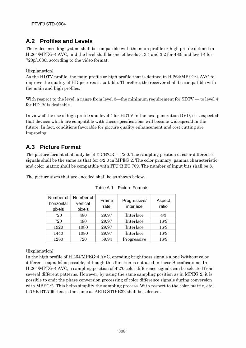
IPTVFJ STD-0004
-308-
A.2 Profiles and Levels The video encoding system shall be compatible with the main profile or high profile defined in H.264/MPEG-4 AVC, and the level shall be one of levels 3, 3.1 and 3.2 for 480i and level 4 for 720p/1080i according to the video format.
(Explanation) As the HDTV profile, the main profile or high profile that is defined in H.264/MPEG-4 AVC to improve the quality of HD pictures is suitable. Therefore, the receiver shall be compatible with the main and high profiles.
With respect to the level, a range from level 3—the minimum requirement for SDTV — to level 4 for HDTV is desirable.
In view of the use of high profile and level 4 for HDTV in the next generation DVD, it is expected that devices which are compatible with these specifications will become widespread in the future. In fact, conditions favorable for picture quality enhancement and cost cutting are improving.
A.3 Picture Format The picture format shall only be of Y:CB:CR = 4:2:0. The sampling position of color difference signals shall be the same as that for 4:2:0 in MPEG-2. The color primary, gamma characteristic and color matrix shall be compatible with ITU-R BT.709. The number of input bits shall be 8.
The picture sizes that are encoded shall be as shown below.
Table A-1 Picture Formats
Number of horizontal
pixels
Number of vertical pixels
Frame rate
Progressive/ interlace
Aspect ratio
720 480 29.97 Interlace 4:3 720 480 29.97 Interlace 16:9 1920 1080 29.97 Interlace 16:9 1440 1080 29.97 Interlace 16:9 1280 720 59.94 Progressive 16:9
(Explanation) In the high profile of H.264/MPEG-4 AVC, encoding brightness signals alone (without color difference signals) is possible, although this function is not used in these Specifications. In H.264/MPEG-4 AVC, a sampling position of 4:2:0 color difference signals can be selected from several different patterns. However, by using the same sampling position as in MPEG-2, it is possible to omit the phase conversion processing of color difference signals during conversion with MPEG-2. This helps simplify the sampling process. With respect to the color matrix, etc., ITU-R BT.709 that is the same as ARIB STD-B32 shall be selected.
IPTVFJ STD-0004
—309—
A.4 Frame Rate The frame rate shall be fixed within a sequence.
(Explanation) H.264/MPEG-4 AVC permits varying the frame interval within a sequence. In these Specifications, however, a fixed frame rate shall be used.
A.5 Picture Structure The unit of encoding is a frame. In the case of interlace, each frame shall contain two fields. The value of pic_struct in the picture timing Supplemental Enhancement Information (SEI) shall be in the range 0 to 8 (includes 3:2 pull-down, frame-doubling/tripling).
(Explanation) H.264/MPEG-4 AVC allows a one-side field structure (e.g., the top field only). In these Specifications, however, each frame must consist of two fields—the top field and the bottom field.
A.6 Data Structure of Bit Stream The sequence parameter set shall contain VUI (Video Usability Information).
The boundary between pictures shall contain an access unit delimiter.
The order of the NAL units making up an access unit and the SEI messages differs according to whether or not the access unit is at the beginning of GOP as described below. NAL units and SEI messages which are not described shall not be operated. Note that pan-scan rectangle SEI, decoded reference picture marking SEI, filler data and end of sequence are not indispensable for the access unit.
Access unit at beginning of GOP
Access unit delimiter (required)
Sequence parameter set (required)
Picture parameter set (required)
SEI
(a) Buffring period SEI (required)
(b) Recovery point SEI
Recovery point SEI is required of a GOP which begins with an I-frame other than IDR.
(c) Picture timing SEI (required)
IPTVFJ STD-0004
-310-
Set the pic_struct_present_flag to 1 and indicate the order of output of the individual fields by pic_struct in the picture timing SEI.
(d) Pan-scan rectangle SEI
The method of operation of this SEI is described in detail in 2.14 “Pan-scan rectangle SEI”.
(e) Decoded reference picture marking SEI
Slice data (pixel value encoded data) (required)
The minimum unit of slice is a macro block string or a macro block pair string. In a GOP beginning with an I-frame other than IDR, regardless of whether the decoding is continued from the preceding GOP or started from the leading I-frame due to channel switching, etc., the slice data shall be so encoded that the slices which do not refer to pictures belonging to the preceding GOP can be decoded and output without being conscious of the continuation from the preceding GOP (see Note 1).
Filler data
End of sequence
Access unit not at beginning of GOP
Access unit delimiter (required)
Picture parameter set (required)
SEI
(f) Picture timing SEI (required)
Set the pic_struct_present_flag to 1 and indicate the order of output of the individual fields by the pic_struct in the picture timing SEI.
(g) Pan-scan rectangle SEI
The method of operation of this SEI is described in detail in 2.14 “Pan-scan rectangle SEI”.
(h) Decoded reference picture marking SEI
Slice data (pixel value encoded data) (required) The minimum unit of slice is a macro block string or a macro block pair string. In a GOP beginning with an I-frame other than IDR, regardless of whether the decoding is continued from the preceding GOP or started from the leading I-frame due to channel switching, etc., the slice data shall be so encoded that the slices which do not refer to pictures belonging to the preceding GOP can be decoded and output without being conscious of the continuation from the preceding GOP (see Note 1).
Filler data
End of sequence
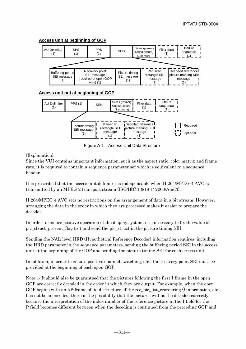
IPTVFJ STD-0004
—311—
Figure A-1 Access Unit Data Structure
(Explanation) Since the VUI contains important information, such as the aspect ratio, color matrix and frame rate, it is required to contain a sequence parameter set which is equivalent to a sequence header.
It is prescribed that the access unit delimiter is indispensable when H.264/MPEG-4 AVC is transmitted by an MPEG-2 transport stream (ISO/IEC 13818-1: 2000/Amd3).
H.264/MPEG-4 AVC sets no restrictions on the arrangement of data in a bit stream. However, arranging the data in the order in which they are processed makes it easier to prepare the decoder.
In order to ensure positive operation of the display system, it is necessary to fix the value of pic_struct_present_flag to 1 and send the pic_struct in the picture timing SEI.
Sending the NAL-level HRD (Hypothetical Reference Decoder) information requires: including the HRD parameter in the sequence parameters, sending the buffering period SEI in the access unit at the beginning of the GOP and sending the picture timing SEI for each access unit.
In addition, in order to ensure positive channel switching, etc., the recovery point SEI must be provided at the beginning of each open GOP.
Note 1: It should also be guaranteed that the pictures following the first I-frame in the open GOP are correctly decoded in the order in which they are output. For example, when the open GOP begins with an I/P-frame of field structure, if the rec_pic_list_reordering () information, etc. has not been encoded, there is the possibility that the pictures will not be decoded correctly because the interpretation of the index number of the reference picture in the I-field for the P-field becomes different between when the decoding is continued from the preceding GOP and
AU Delimiter (1)
SPS (1)
PPS (1)
SEIs Slices (primary coded picture)
(1 or more)
Filler data (1)
End of sequence
(1)
Buffering period SEI message
(1)
Recovery point SEI message
(required of open GOP only) (1)
Picture timing SEI message
(1)
Pan-scan rectangle SEI
message (1)
Decoded reference picture marking SEI
message (1)
AU Delimiter (1)
PPS (1) SEIs Slices (Primary Coded Picture)
(1 or more)
Filler data (1)
End of sequence
(1)
Picture timing SEI message
(1)
Pan-scan rectangle SEI
message (1)
Decoded reference picture marking SEI
message (1)
Access unit not at beginning of GOP
Access unit at beginning of GOP
Required Optional
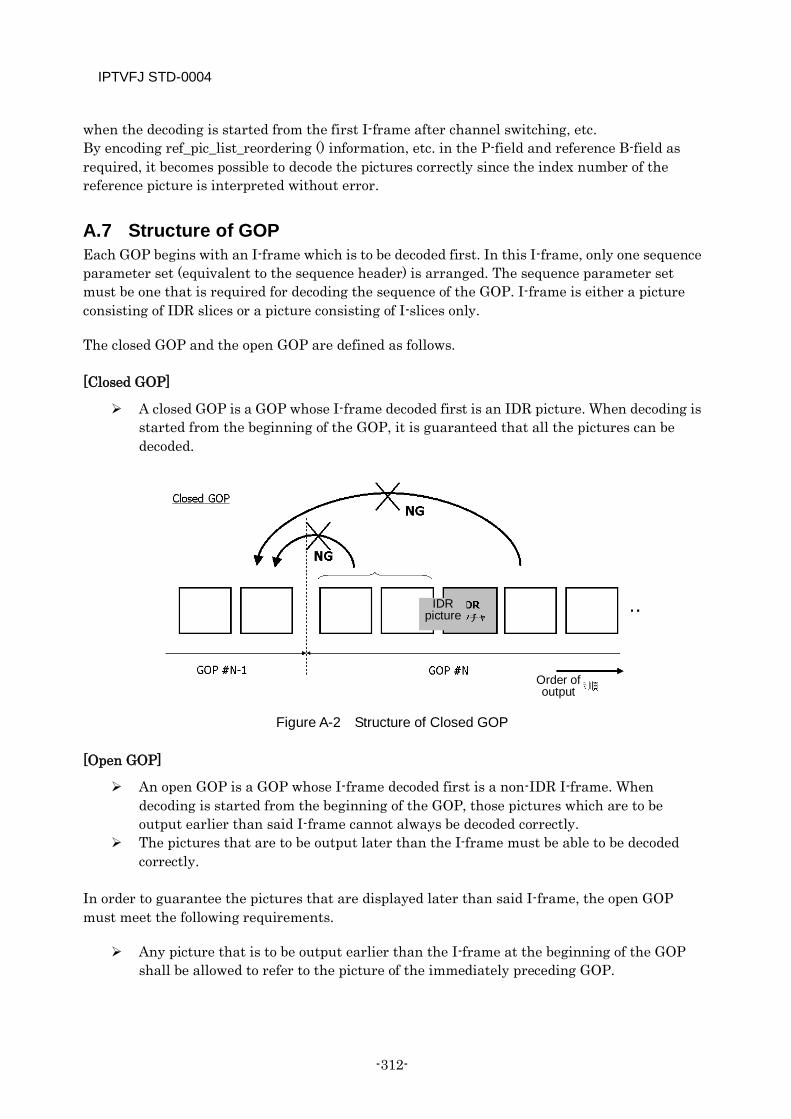
IPTVFJ STD-0004
-312-
when the decoding is started from the first I-frame after channel switching, etc. By encoding ref_pic_list_reordering () information, etc. in the P-field and reference B-field as required, it becomes possible to decode the pictures correctly since the index number of the reference picture is interpreted without error.
A.7 Structure of GOP Each GOP begins with an I-frame which is to be decoded first. In this I-frame, only one sequence parameter set (equivalent to the sequence header) is arranged. The sequence parameter set must be one that is required for decoding the sequence of the GOP. I-frame is either a picture consisting of IDR slices or a picture consisting of I-slices only.
The closed GOP and the open GOP are defined as follows.
[Closed GOP]
A closed GOP is a GOP whose I-frame decoded first is an IDR picture. When decoding is started from the beginning of the GOP, it is guaranteed that all the pictures can be decoded.
Figure A-2 Structure of Closed GOP
[Open GOP]
An open GOP is a GOP whose I-frame decoded first is a non-IDR I-frame. When decoding is started from the beginning of the GOP, those pictures which are to be output earlier than said I-frame cannot always be decoded correctly.
The pictures that are to be output later than the I-frame must be able to be decoded correctly.
In order to guarantee the pictures that are displayed later than said I-frame, the open GOP must meet the following requirements.
Any picture that is to be output earlier than the I-frame at the beginning of the GOP shall be allowed to refer to the picture of the immediately preceding GOP.
IDR picture
Order of output
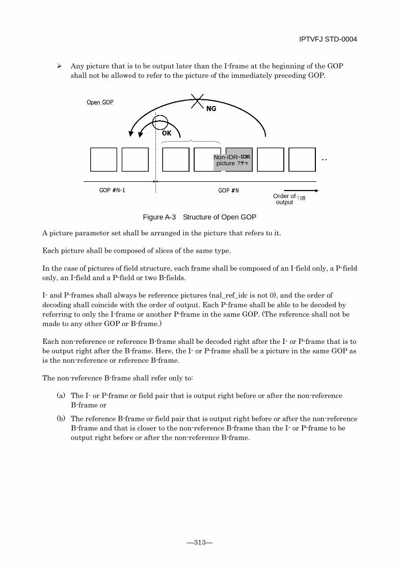
IPTVFJ STD-0004
—313—
Any picture that is to be output later than the I-frame at the beginning of the GOP shall not be allowed to refer to the picture of the immediately preceding GOP.
Figure A-3 Structure of Open GOP
A picture parameter set shall be arranged in the picture that refers to it.
Each picture shall be composed of slices of the same type.
In the case of pictures of field structure, each frame shall be composed of an I-field only, a P-field only, an I-field and a P-field or two B-fields.
I- and P-frames shall always be reference pictures (nal_ref_idc is not 0), and the order of decoding shall coincide with the order of output. Each P-frame shall be able to be decoded by referring to only the I-frame or another P-frame in the same GOP. (The reference shall not be made to any other GOP or B-frame.)
Each non-reference or reference B-frame shall be decoded right after the I- or P-frame that is to be output right after the B-frame. Here, the I- or P-frame shall be a picture in the same GOP as is the non-reference or reference B-frame.
The non-reference B-frame shall refer only to:
(a) The I- or P-frame or field pair that is output right before or after the non-reference B-frame or
(b) The reference B-frame or field pair that is output right before or after the non-reference B-frame and that is closer to the non-reference B-frame than the I- or P-frame to be output right before or after the non-reference B-frame.
Non-IDR picture
Order of output
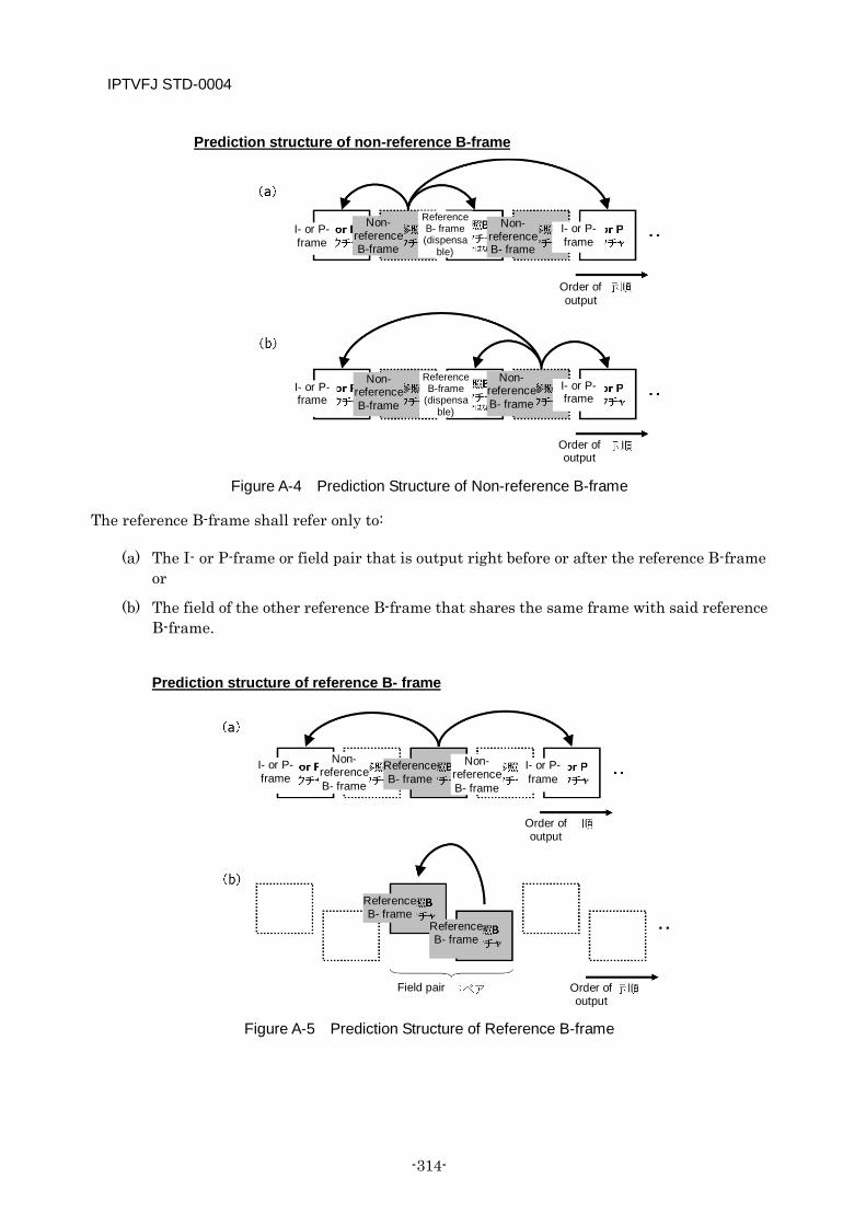
IPTVFJ STD-0004
-314-
Figure A-4 Prediction Structure of Non-reference B-frame
The reference B-frame shall refer only to:
(a) The I- or P-frame or field pair that is output right before or after the reference B-frame or
(b) The field of the other reference B-frame that shares the same frame with said reference B-frame.
Figure A-5 Prediction Structure of Reference B-frame
I- or P- frame
Non- reference B-frame
Reference B- frame (dispensa
ble)
Non- reference B- frame
I- or P- frame
Order of output
Prediction structure of reference B- frame
I- or P- frame
Non- reference B- frame
Reference B- frame
I- or P- frame
Non- reference B-frame
Reference B-frame
(dispensa ble)
Non- reference B- frame
I- or P- frame
Order of output
Reference B- frame
Reference B- frame
Order of output
Order of output
I- or P- frame
Non- reference B- frame
Field pair
Prediction structure of non-reference B-frame

IPTVFJ STD-0004
—315—
There are two types of B-frames — the B-frame that can be referred to by other pictures (nal_ref_idc ≠ 0) and the B-frame that cannot be referred to by other pictures (nal_ref_idc = 0). In this text, the former is called the reference B-frame and the latter is called the non-reference B-frame.
There must not be reordering between non-reference B-frames. (For non-reference B-frames, the order of decoding shall coincide with the order of output.)
When a reference B-frame is subjected to decoded reference picture marking, the content of the decoded reference picture marking shall be retransmitted by the decoded reference picture marking SEI in the I- or P-frame that is to be decoded right after the reference B-frame.
The maximum number of frames or field pairs of consecutive B-frames (non-reference or reference B-frames) shall be 3.
In any GOP, the difference between the time of decoding of the I-frame decoded first and the time of output of the picture output first shall not exceed the interval between two frames. (When the decoding is started from the beginning of the GOP, the output can be started within the time interval between two frames.)
As a rule, the GOP length shall be 500 ms (max. 1 sec) (see Note 2).
Note 2: In view of the fact that increasing the GOP length improves the picture quality but influence on channel switching and the amount of CPB buffering, the GOP length prescribed above is the most desirable.
(Explanation) In H.264/MPEG-4 AVC, I-slices, P-slices and B-slices are allowed to coexist in a picture and the P-frame can use the B-frame for prediction. Thus, it permits implementing a flexible prediction structure. However, by setting certain restrictions on the GOP structure as in MPEG-2, it becomes easier to implement the decoder. In addition, it becomes possible to implement fast playback and other convenient functions when a stream is recorded.
One picture parameter set must be included in each picture.
(Explanation) In H.264/MPEG-4 AVC, it is possible to transmit more than one picture parameter set at a time and design a stream structure in which a previously-sent picture parameter set can be referred to by the succeeding picture. However, by including a picture parameter set in each picture as in the case of MPEG-2, it becomes possible to eliminate the need to hold picture parameter sets in the decoder. This helps simplify the processing.
A.8 Restrictions on Encoding Tools The MinLumaBiPredSize shall be 8 × 8 (even when the level is lower than Level 4).
IPTVFJ STD-0004
-316-
The maximum number of reference frames (num_ref_frames) shall be 4. The CPB size used shall not exceed 16 Mbits.
(Explanation) In H.264/MPEG-4 AVC, there is an encoding tool which can be used only at levels lower than Level 4 (bidirectional motion compensation for block sizes smaller than 8×8 pixels). However, implementing HDTV requires an encoding tool compatible with Level 4. By prohibiting the use of an encoding tool which is incompatible with Level 4, it becomes easier to implement the decoder.
The number of reference frames that can be used in decoding HDTV at Level 4 is 4. Therefore, by setting the maximum number of reference frames at 4 regardless of the block size and level, it becomes easier to implement the decoder.
The CPB buffer size shall be the required minimum in consideration of the capacity of memory and the ease of AV synchronization. Since the maximum GOP length is 1 sec, a CPB size corresponding to 16 Mbps is suitable.
In IP broadcasts, switching between the two variable-length coding systems — CAVLC and CABAC — shall be allowed only while the broadcast is off the air.
(Explanation) The above specification eliminates the need for any arrangement to switch the two variable-length coding systems instantaneously so that the video transmission is not interrupted. This makes it easier to implement the decoder.
The type of POC (Picture Order Count) shall be Type 0.
(Explanation) Type 1 is complicated. Besides, in the range of bit rates defined in these Specifications, Type 1 is not very effective to reduce the amount of data encoding. Type 0 has the advantages of all the other types. In order to minimize the values of the syntax elements, Type 0 shall be used exclusively.
A.9 HRD Conformance The HRD shall conform to the output timing of Type 2 (NAL Level).
A.10 Multiplexing Based on MPEG-2 System Standard
PES packet
Each PES packet shall consist of access units which make up one frame or one field pair. (It must not contain more than one frame or field pair.)
IPTVFJ STD-0004
—317—
A PTS must always be transmitted in the PES header. The receiver shall implement the decode start control and output control according to the PTS and DTS in the PES header. The value of PTS_DTS_flag shall be set as follows.
11b: For a PES packet which contains an I-frame or a P-frame or a B-frame whose PTS and DTS are different.
10b: For a PES packet which contains a B-frame whose PTS and DTS are equal.
STD delay
Data input to the CPB shall be decoded within 1 second.
Descriptors
The following descriptors that are defined in the MPEG-2 System Extended Standard (ISO/IEC 13818-1: 2000/Amd 3:2004) for H.264/MPEG-4 AVC shall not be operated.
AVC video descriptor AVC timing and HRD descriptor
A.11 Transmission of Identifier Indicating End of Sequence As the identifier that indicates the end of a sequence, the end-of-sequence NAL unit shall be
used. (The end-of-stream NAL unit shall not be operated.)
The end-of-sequence NAL unit shall be transmitted right before the leading access unit of a closed GOP (GOP beginning with an IDR picture).
When the receiver receives an end-of-sequence NAL unit, it is desirable that the receiver should freeze-display the video data it received right before the end-of-sequence NAL unit till the video data that is transmitted subsequently is decoded and displayed properly. This does not mean that the video data received right before the end-of-sequence NAL unit is always freeze-displayed for a certain time, because when the video data that is transmitted after the end-of-sequence NAL unit can be decoded and displayed without delay, the video data before and after the end-of-sequence NAL unit are connected together seamlessly.
A.12 Seamless Switching in IP Broadcast Concerning the seamless switching within the same codec (H.264/MPEG-4 AVC) in IP broadcast, the operation described in Chapter 4 “Seamless Switching” of ARIB STD-B32 Part 1 Appendix shall be applied.
Changing number of effective samples
(1) Method of operation at transmitting side
1. Use an end-of-sequence NAL unit to terminate the sequence at the operation switching point. Then, newly specify the number of samples in the sequence parameter set of the next GOP.
2. The leading GOP in the new operation sequence shall be a closed GOP. 3. The values of cpb_size_scale and cpb_size_value_minus1 in the hrd_parameters()
shall be kept unchanged before and after the switching of operation.
IPTVFJ STD-0004
-318-
4. The difference between the time of decoding of the I-frame that is decoded first in the GOP and the time of output of the picture that is output first in the GOP shall be kept unchanged before and after the switching of operation.
5. The continuity of PTS and DTS shall be guaranteed.
(2) Operation at receiver side
The receiver sets the new mode of operation using the number-of-pixels parameter contained in the sequence parameter set it has received. Even when the receiver has not received an end-of-sequence NAL unit, it shall set the mode of operation to the new one according to the contents of the sequence parameter set it has received.
Changing aspect ratio in 525i system
(1) Method of operation at transmitting side
1. Use an end-of-sequence NAL unit to terminate the sequence at the operation switching point. Then, specify a new aspect ratio in the sequence parameter set of the next GOP.
2. The leading GOP in the new operation sequence shall be a closed GOP. 3. The values of cpb_size_scale and cpb_size_value_minus1 in the hrd_parameters()
shall be kept unchanged before and after the switching of operation. 4. The difference between the decoding time of the I-frame decoded first in the GOP
and the output time of the picture output first in the GOP shall be kept unchanged before and after the switching of operation.
5. The continuity of PTS and DTS shall be guaranteed.
(2) Operation at receiver side
The receiver sets the new mode of operation using the aspect ratio parameter contained in the sequence parameter set it has received. Even when the receiver has not received an end-of-sequence NAL unit, it shall set the new mode of operation according to the contents of the sequence parameter set it has received.
Changing bit rate
(1) Method of operation at transmitting side
1. Always operate in the variable rate mode. 2. Set the value of cbr_flag in the hrd_parameters() to 0. 3. An end-of-sequence NAL unit shall not be inserted at the change point of the
transmission bit rate. 4. The values of cpb_size_scale and cpb_size_value_minus1 in the hrd_parameters()
shall be kept unchanged before and after the switching of operation. 5. The difference between the decoding time of the I-frame that is decoded first in the
GOP and the output time of the picture that is output first in the GOP shall be kept unchanged before and after the switching of operation.
6. The continuity of PTS and DTS shall be guaranteed.
(2) Operation at the receiver side
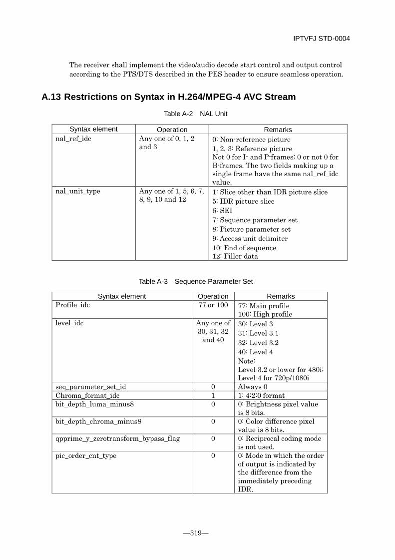
IPTVFJ STD-0004
—319—
The receiver shall implement the video/audio decode start control and output control according to the PTS/DTS described in the PES header to ensure seamless operation.
A.13 Restrictions on Syntax in H.264/MPEG-4 AVC Stream
Table A-2 NAL Unit
Syntax element Operation Remarks nal_ref_idc Any one of 0, 1, 2
and 3 0: Non-reference picture 1, 2, 3: Reference picture Not 0 for I- and P-frames; 0 or not 0 for B-frames. The two fields making up a single frame have the same nal_ref_idc value.
nal_unit_type Any one of 1, 5, 6, 7, 8, 9, 10 and 12
1: Slice other than IDR picture slice 5: IDR picture slice 6: SEI 7: Sequence parameter set 8: Picture parameter set 9: Access unit delimiter 10: End of sequence 12: Filler data
Table A-3 Sequence Parameter Set
Syntax element Operation Remarks Profile_idc 77 or 100 77: Main profile
100: High profile level_idc Any one of
30, 31, 32 and 40
30: Level 3 31: Level 3.1 32: Level 3.2 40: Level 4 Note: Level 3.2 or lower for 480i; Level 4 for 720p/1080i
seq_parameter_set_id 0 Always 0 Chroma_format_idc 1 1: 4:2:0 format bit_depth_luma_minus8 0 0: Brightness pixel value
is 8 bits. bit_depth_chroma_minus8 0 0: Color difference pixel
value is 8 bits. qpprime_y_zerotransform_bypass_flag 0 0: Reciprocal coding mode
is not used. pic_order_cnt_type 0 0: Mode in which the order
of output is indicated by the difference from the immediately preceding IDR.
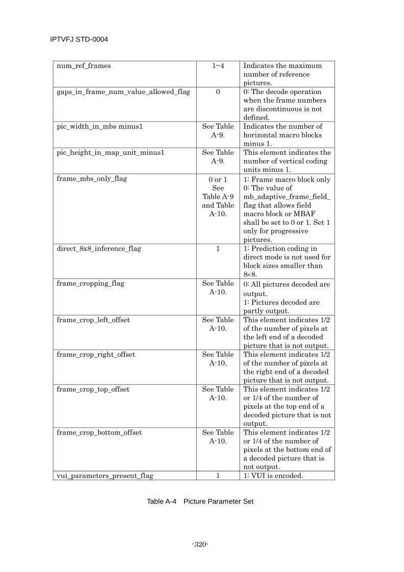
IPTVFJ STD-0004
-320-
num_ref_frames 1~4 Indicates the maximum number of reference pictures.
gaps_in_frame_num_value_allowed_flag 0 0: The decode operation when the frame numbers are discontinuous is not defined.
pic_width_in_mbs minus1 See Table A-9.
Indicates the number of horizontal macro blocks minus 1.
pic_height_in_map_unit_minus1 See Table A-9.
This element indicates the number of vertical coding units minus 1.
frame_mbs_only_flag 0 or 1 See
Table A-9 and Table
A-10.
1: Frame macro block only 0: The value of mb_adaptive_frame_field_flag that allows field macro block or MBAF shall be set to 0 or 1. Set 1 only for progressive pictures.
direct_8x8_inference_flag 1 1: Prediction coding in direct mode is not used for block sizes smaller than 8×8.
frame_cropping_flag See Table A-10.
0: All pictures decoded are output. 1: Pictures decoded are partly output.
frame_crop_left_offset See Table A-10.
This element indicates 1/2 of the number of pixels at the left end of a decoded picture that is not output.
frame_crop_right_offset See Table A-10.
This element indicates 1/2 of the number of pixels at the right end of a decoded picture that is not output.
frame_crop_top_offset See Table A-10.
This element indicates 1/2 or 1/4 of the number of pixels at the top end of a decoded picture that is not output.
frame_crop_bottom_offset See Table A-10.
This element indicates 1/2 or 1/4 of the number of pixels at the bottom end of a decoded picture that is not output.
vui_parameters_present_flag 1 1: VUI is encoded.
Table A-4 Picture Parameter Set
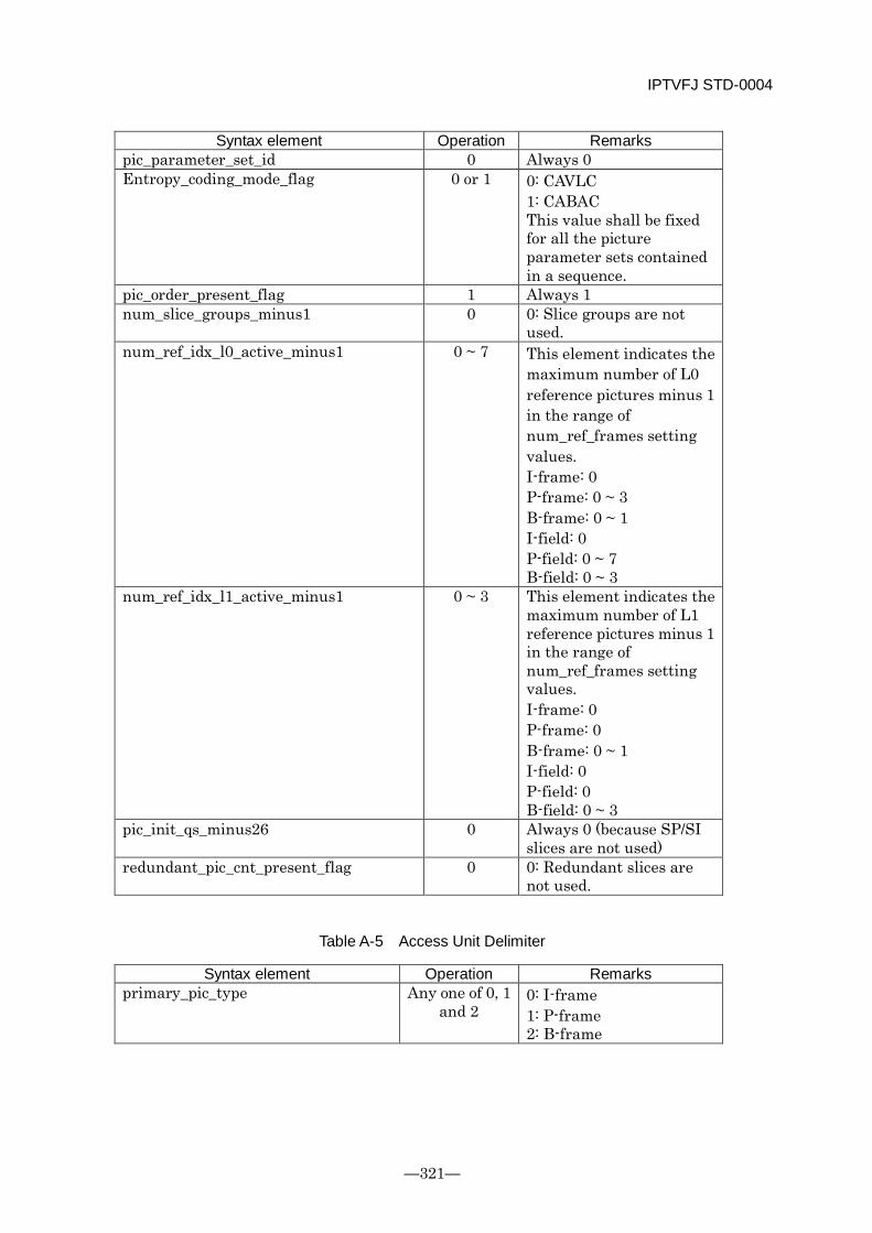
IPTVFJ STD-0004
—321—
Syntax element Operation Remarks pic_parameter_set_id 0 Always 0 Entropy_coding_mode_flag 0 or 1 0: CAVLC
1: CABAC This value shall be fixed for all the picture parameter sets contained in a sequence.
pic_order_present_flag 1 Always 1 num_slice_groups_minus1 0 0: Slice groups are not
used. num_ref_idx_l0_active_minus1 0 ~ 7 This element indicates the
maximum number of L0 reference pictures minus 1 in the range of num_ref_frames setting values. I-frame: 0 P-frame: 0 ~ 3 B-frame: 0 ~ 1 I-field: 0 P-field: 0 ~ 7 B-field: 0 ~ 3
num_ref_idx_l1_active_minus1 0 ~ 3 This element indicates the maximum number of L1 reference pictures minus 1 in the range of num_ref_frames setting values. I-frame: 0 P-frame: 0 B-frame: 0 ~ 1 I-field: 0 P-field: 0 B-field: 0 ~ 3
pic_init_qs_minus26 0 Always 0 (because SP/SI slices are not used)
redundant_pic_cnt_present_flag 0 0: Redundant slices are not used.
Table A-5 Access Unit Delimiter
Syntax element Operation Remarks primary_pic_type Any one of 0, 1
and 2 0: I-frame 1: P-frame 2: B-frame
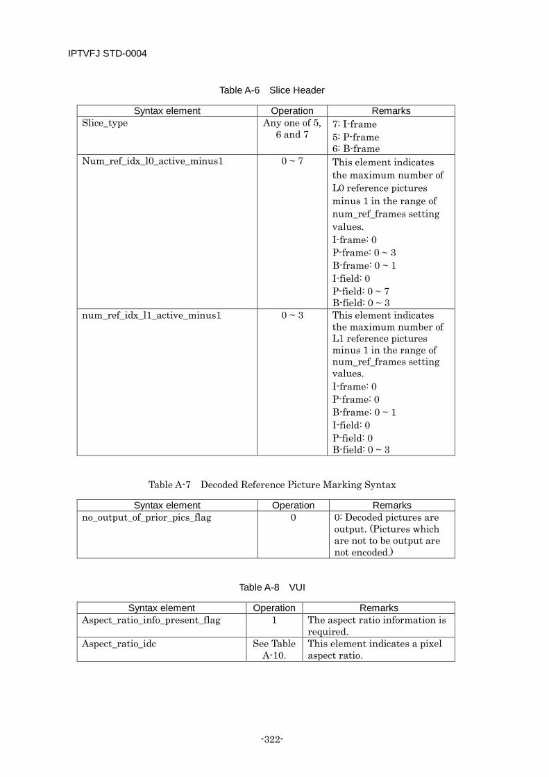
IPTVFJ STD-0004
-322-
Table A-6 Slice Header
Syntax element Operation Remarks Slice_type Any one of 5,
6 and 7 7: I-frame 5: P-frame 6: B-frame
Num_ref_idx_l0_active_minus1 0 ~ 7 This element indicates the maximum number of L0 reference pictures minus 1 in the range of num_ref_frames setting values. I-frame: 0 P-frame: 0 ~ 3 B-frame: 0 ~ 1 I-field: 0 P-field: 0 ~ 7 B-field: 0 ~ 3
num_ref_idx_l1_active_minus1 0 ~ 3 This element indicates the maximum number of L1 reference pictures minus 1 in the range of num_ref_frames setting values. I-frame: 0 P-frame: 0 B-frame: 0 ~ 1 I-field: 0 P-field: 0 B-field: 0 ~ 3
Table A-7 Decoded Reference Picture Marking Syntax
Syntax element Operation Remarks no_output_of_prior_pics_flag 0 0: Decoded pictures are
output. (Pictures which are not to be output are not encoded.)
Table A-8 VUI
Syntax element Operation Remarks Aspect_ratio_info_present_flag 1 The aspect ratio information is
required. Aspect_ratio_idc See Table
A-10. This element indicates a pixel aspect ratio.
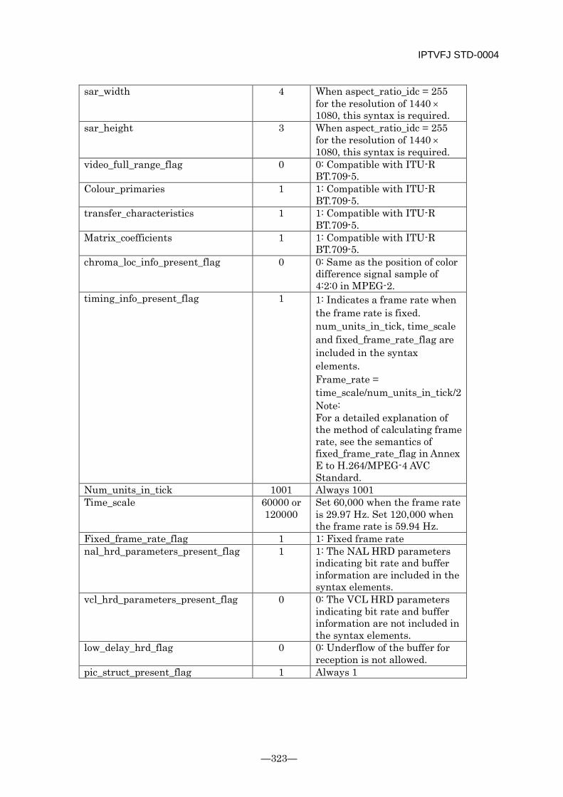
IPTVFJ STD-0004
—323—
sar_width 4 When aspect_ratio_idc = 255 for the resolution of 1440 × 1080, this syntax is required.
sar_height 3 When aspect_ratio_idc = 255 for the resolution of 1440 × 1080, this syntax is required.
video_full_range_flag 0 0: Compatible with ITU-R BT.709-5.
Colour_primaries 1 1: Compatible with ITU-R BT.709-5.
transfer_characteristics 1 1: Compatible with ITU-R BT.709-5.
Matrix_coefficients 1 1: Compatible with ITU-R BT.709-5.
chroma_loc_info_present_flag 0 0: Same as the position of color difference signal sample of 4:2:0 in MPEG-2.
timing_info_present_flag 1 1: Indicates a frame rate when the frame rate is fixed. num_units_in_tick, time_scale and fixed_frame_rate_flag are included in the syntax elements. Frame_rate = time_scale/num_units_in_tick/2 Note: For a detailed explanation of the method of calculating frame rate, see the semantics of fixed_frame_rate_flag in Annex E to H.264/MPEG-4 AVC Standard.
Num_units_in_tick 1001 Always 1001 Time_scale 60000 or
120000 Set 60,000 when the frame rate is 29.97 Hz. Set 120,000 when the frame rate is 59.94 Hz.
Fixed_frame_rate_flag 1 1: Fixed frame rate nal_hrd_parameters_present_flag 1 1: The NAL HRD parameters
indicating bit rate and buffer information are included in the syntax elements.
vcl_hrd_parameters_present_flag 0 0: The VCL HRD parameters indicating bit rate and buffer information are not included in the syntax elements.
low_delay_hrd_flag 0 0: Underflow of the buffer for reception is not allowed.
pic_struct_present_flag 1 Always 1
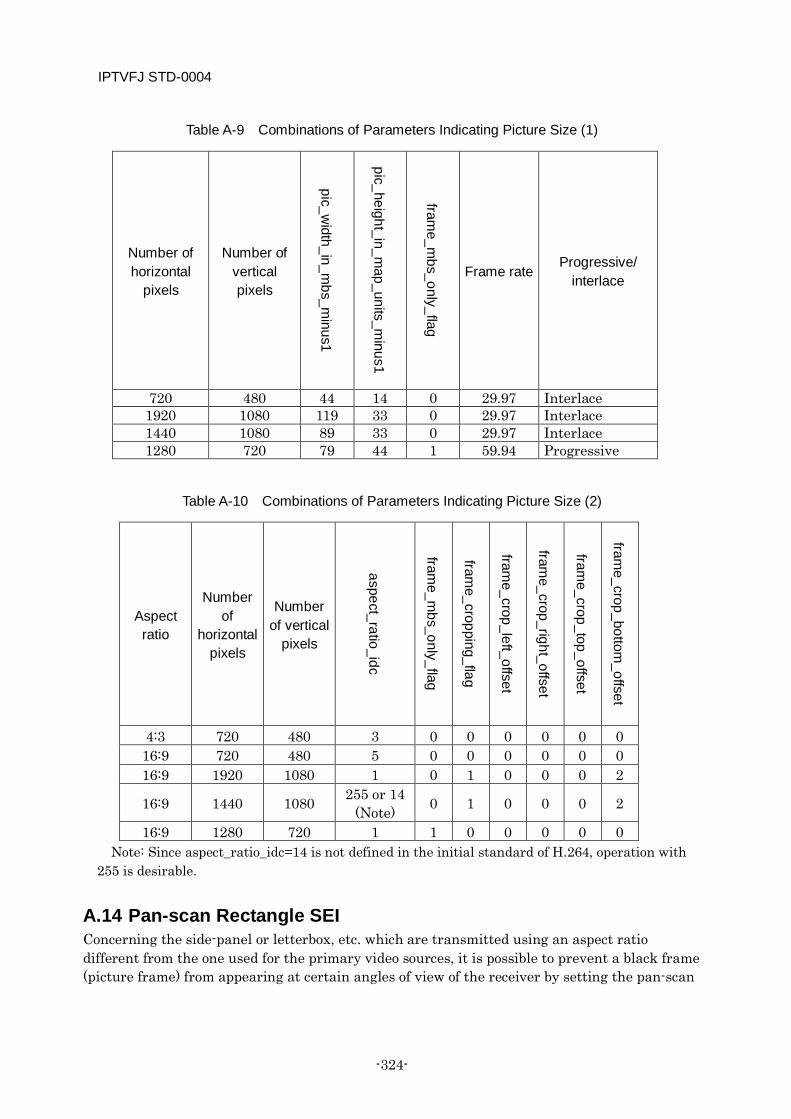
IPTVFJ STD-0004
-324-
Table A-9 Combinations of Parameters Indicating Picture Size (1)
Number of horizontal
pixels
Number of vertical pixels
pic_width_in_m
bs_minus1
pic_height_in_map_units_m
inus1
frame_m
bs_only_flag
Frame rate Progressive/
interlace
720 480 44 14 0 29.97 Interlace 1920 1080 119 33 0 29.97 Interlace 1440 1080 89 33 0 29.97 Interlace 1280 720 79 44 1 59.94 Progressive
Table A-10 Combinations of Parameters Indicating Picture Size (2)
Aspect ratio
Number of
horizontal pixels
Number of vertical
pixels
aspect_ratio_idc
frame_m
bs_only_flag
frame_cropping_flag
frame_crop_left_offset
frame_crop_right_offset
frame_crop_top_offset
frame_crop_bottom
_offset
4:3 720 480 3 0 0 0 0 0 0 16:9 720 480 5 0 0 0 0 0 0 16:9 1920 1080 1 0 1 0 0 0 2
16:9 1440 1080 255 or 14 (Note) 0 1 0 0 0 2
16:9 1280 720 1 1 0 0 0 0 0 Note: Since aspect_ratio_idc=14 is not defined in the initial standard of H.264, operation with
255 is desirable.
A.14 Pan-scan Rectangle SEI Concerning the side-panel or letterbox, etc. which are transmitted using an aspect ratio different from the one used for the primary video sources, it is possible to prevent a black frame (picture frame) from appearing at certain angles of view of the receiver by setting the pan-scan

IPTVFJ STD-0004
—325—
rectangle parameters as described below. Here, the display format during operation of the pan-scan rectangle shall be as shown in Fig. 5-1 “Desirable display format for monitors with aspect ratio 4:3/16:9” in Chapter 5 “Restrictions on Coding Parameters” of STD-B32 Part 1.
When operating the pan-scan rectangle, pan-scan rectangle SEI must be encoded in the leading I-frame of the GOP (the IDR I-frame for a closed GOP and the non-IDR I-frame for an open GOP). (The pan-scan rectangle SEI must not be encoded when the pan-scan rectangle is not operated.)
The values of the individual parameters for the above operation are shown in the following table.
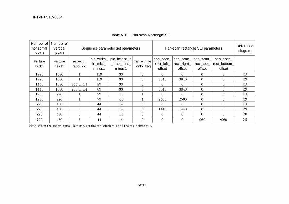
IPTVFJ STD-0004
-326-
Table A-11 Pan-scan Rectangle SEI
Number of horizontal
pixels
Number of vertical pixels
Sequence parameter set parameters Pan-scan rectangle SEI parameters Reference diagram
Picture width
Picture height
aspect_ ratio_idc
pic_width_ in_mbs_ minus1
pic_height_in_map_units_
minus1
frame_mbs_only_flag
pan_scan_ rect_left_
offset
pan_scan_ rect_right_
offset
pan_scan_ rect_top_
offset
pan_scan_ rect_bottom_
offset
1920 1080 1 119 33 0 0 0 0 0 (1) 1920 1080 1 119 33 0 3840 -3840 0 0 (2) 1440 1080 255 or 14 89 33 0 0 0 0 0 (1) 1440 1080 255 or 14 89 33 0 3840 -3840 0 0 (2) 1280 720 1 79 44 1 0 0 0 0 (1) 1280 720 1 79 44 1 2560 -2560 0 0 (2) 720 480 5 44 14 0 0 0 0 0 (1) 720 480 5 44 14 0 1440 -1440 0 0 (2) 720 480 3 44 14 0 0 0 0 0 (3) 720 480 3 44 14 0 0 0 960 -960 (4)
Note: When the aspect_ratio_idc = 255, set the sar_width to 4 and the sar_height to 3.
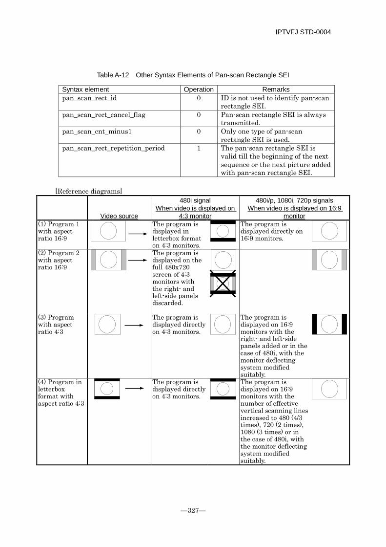
IPTVFJ STD-0004
—327—
Table A-12 Other Syntax Elements of Pan-scan Rectangle SEI
Syntax element Operation Remarks pan_scan_rect_id 0 ID is not used to identify pan-scan
rectangle SEI. pan_scan_rect_cancel_flag 0 Pan-scan rectangle SEI is always
transmitted. pan_scan_cnt_minus1 0 Only one type of pan-scan
rectangle SEI is used. pan_scan_rect_repetition_period 1 The pan-scan rectangle SEI is
valid till the beginning of the next sequence or the next picture added with pan-scan rectangle SEI.
[Reference diagrams]
480i signal
Video source
480i/p, 1080i, 720p signals When video is displayed on
4:3 monitor (1) Program 1 with aspect ratio 16:9
When video is displayed on 16:9 monitor
The program is displayed in letterbox format on 4:3 monitors.
The program is displayed directly on 16:9 monitors.
(2) Program 2 with aspect ratio 16:9
The program is displayed on the full 480x720 screen of 4:3 monitors with the right- and left-side panels discarded.
(3) Program with aspect ratio 4:3
The program is displayed directly on 4:3 monitors.
The program is displayed on 16:9 monitors with the right- and left-side panels added or in the case of 480i, with the monitor deflecting system modified suitably.
(4) Program in letterbox format with aspect ratio 4:3
The program is displayed directly on 4:3 monitors.
The program is displayed on 16:9 monitors with the number of effective vertical scanning lines increased to 480 (4/3 times), 720 (2 times), 1080 (3 times) or in the case of 480i, with the monitor deflecting system modified suitably.
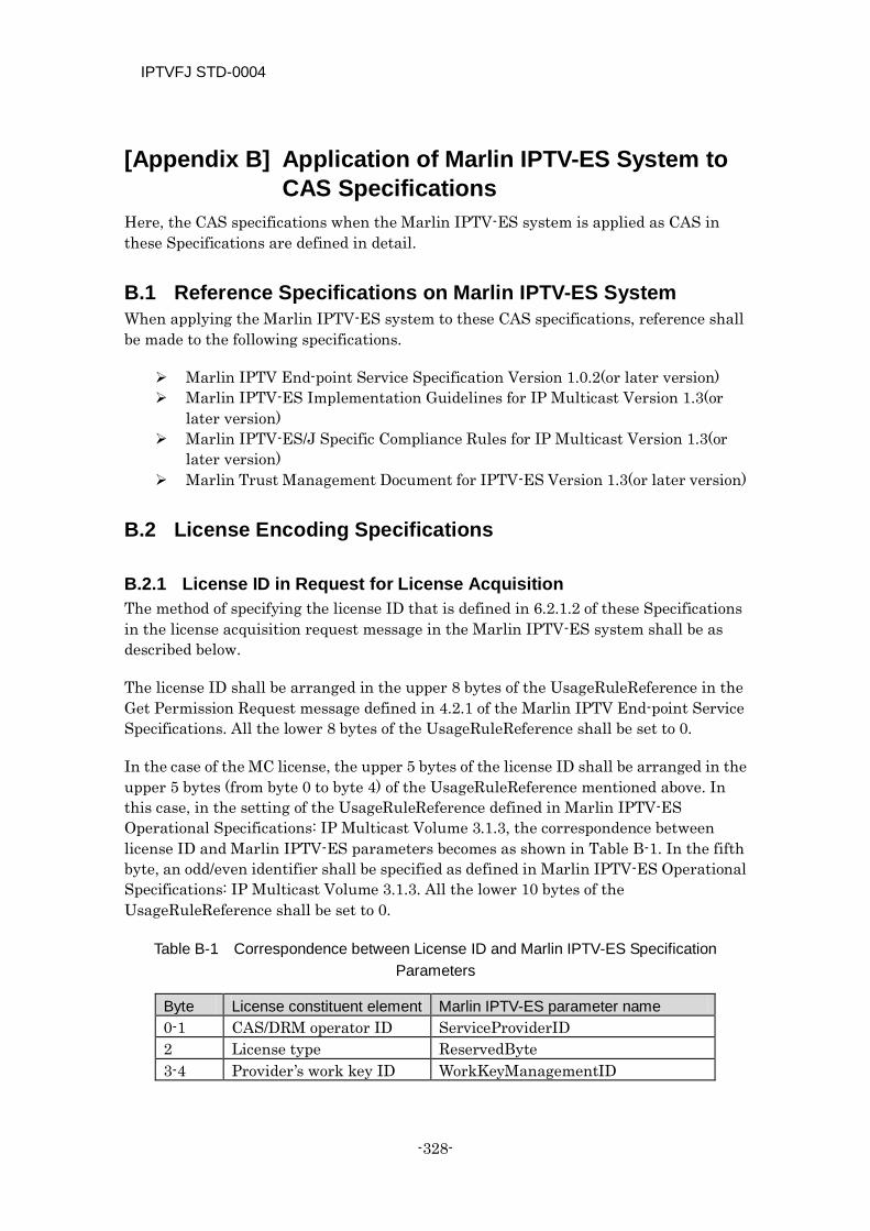
IPTVFJ STD-0004
-328-
[Appendix B] Application of Marlin IPTV-ES System to CAS Specifications
Here, the CAS specifications when the Marlin IPTV-ES system is applied as CAS in these Specifications are defined in detail.
B.1 Reference Specifications on Marlin IPTV-ES System When applying the Marlin IPTV-ES system to these CAS specifications, reference shall be made to the following specifications.
Marlin IPTV End-point Service Specification Version 1.0.2(or later version) Marlin IPTV-ES Implementation Guidelines for IP Multicast Version 1.3(or
later version) Marlin IPTV-ES/J Specific Compliance Rules for IP Multicast Version 1.3(or
later version) Marlin Trust Management Document for IPTV-ES Version 1.3(or later version)
B.2 License Encoding Specifications
B.2.1 License ID in Request for License Acquisition The method of specifying the license ID that is defined in 6.2.1.2 of these Specifications in the license acquisition request message in the Marlin IPTV-ES system shall be as described below.
The license ID shall be arranged in the upper 8 bytes of the UsageRuleReference in the Get Permission Request message defined in 4.2.1 of the Marlin IPTV End-point Service Specifications. All the lower 8 bytes of the UsageRuleReference shall be set to 0.
In the case of the MC license, the upper 5 bytes of the license ID shall be arranged in the upper 5 bytes (from byte 0 to byte 4) of the UsageRuleReference mentioned above. In this case, in the setting of the UsageRuleReference defined in Marlin IPTV-ES Operational Specifications: IP Multicast Volume 3.1.3, the correspondence between license ID and Marlin IPTV-ES parameters becomes as shown in Table B-1. In the fifth byte, an odd/even identifier shall be specified as defined in Marlin IPTV-ES Operational Specifications: IP Multicast Volume 3.1.3. All the lower 10 bytes of the UsageRuleReference shall be set to 0.
Table B-1 Correspondence between License ID and Marlin IPTV-ES Specification Parameters
Byte License constituent element Marlin IPTV-ES parameter name 0-1 CAS/DRM operator ID ServiceProviderID 2 License type ReservedByte 3-4 Provider’s work key ID WorkKeyManagementID
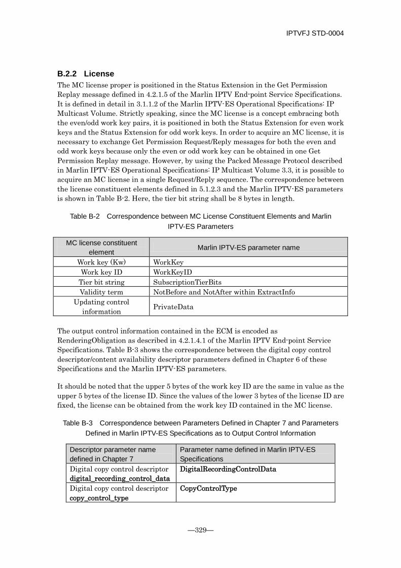
IPTVFJ STD-0004
—329—
B.2.2 License The MC license proper is positioned in the Status Extension in the Get Permission Replay message defined in 4.2.1.5 of the Marlin IPTV End-point Service Specifications. It is defined in detail in 3.1.1.2 of the Marlin IPTV-ES Operational Specifications: IP Multicast Volume. Strictly speaking, since the MC license is a concept embracing both the even/odd work key pairs, it is positioned in both the Status Extension for even work keys and the Status Extension for odd work keys. In order to acquire an MC license, it is necessary to exchange Get Permission Request/Reply messages for both the even and odd work keys because only the even or odd work key can be obtained in one Get Permission Replay message. However, by using the Packed Message Protocol described in Marlin IPTV-ES Operational Specifications: IP Multicast Volume 3.3, it is possible to acquire an MC license in a single Request/Reply sequence. The correspondence between the license constituent elements defined in 5.1.2.3 and the Marlin IPTV-ES parameters is shown in Table B-2. Here, the tier bit string shall be 8 bytes in length.
Table B-2 Correspondence between MC License Constituent Elements and Marlin IPTV-ES Parameters
MC license constituent element Marlin IPTV-ES parameter name
Work key (Kw) WorkKey Work key ID WorkKeyID
Tier bit string SubscriptionTierBits Validity term NotBefore and NotAfter within ExtractInfo
Updating control information PrivateData
The output control information contained in the ECM is encoded as RenderingObligation as described in 4.2.1.4.1 of the Marlin IPTV End-point Service Specifications. Table B-3 shows the correspondence between the digital copy control descriptor/content availability descriptor parameters defined in Chapter 6 of these Specifications and the Marlin IPTV-ES parameters.
It should be noted that the upper 5 bytes of the work key ID are the same in value as the upper 5 bytes of the license ID. Since the values of the lower 3 bytes of the license ID are fixed, the license can be obtained from the work key ID contained in the MC license.
Table B-3 Correspondence between Parameters Defined in Chapter 7 and Parameters Defined in Marlin IPTV-ES Specifications as to Output Control Information
Descriptor parameter name defined in Chapter 7
Parameter name defined in Marlin IPTV-ES Specifications
Digital copy control descriptor digital_recording_control_data
DigitalRecordingControlData
Digital copy control descriptor copy_control_type
CopyControlType
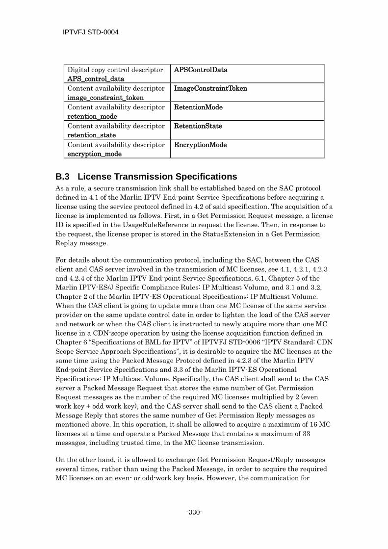
IPTVFJ STD-0004
-330-
Digital copy control descriptor APS_control_data
APSControlData
Content availability descriptor image_constraint_token
ImageConstraintToken
Content availability descriptor retention_mode
RetentionMode
Content availability descriptor retention_state
RetentionState
Content availability descriptor encryption_mode
EncryptionMode
B.3 License Transmission Specifications As a rule, a secure transmission link shall be established based on the SAC protocol defined in 4.1 of the Marlin IPTV End-point Service Specifications before acquiring a license using the service protocol defined in 4.2 of said specification. The acquisition of a license is implemented as follows. First, in a Get Permission Request message, a license ID is specified in the UsageRuleReference to request the license. Then, in response to the request, the license proper is stored in the StatusExtension in a Get Permission Replay message.
For details about the communication protocol, including the SAC, between the CAS client and CAS server involved in the transmission of MC licenses, see 4.1, 4.2.1, 4.2.3 and 4.2.4 of the Marlin IPTV End-point Service Specifications, 6.1, Chapter 5 of the Marlin IPTV-ES/J Specific Compliance Rules: IP Multicast Volume, and 3.1 and 3.2, Chapter 2 of the Marlin IPTV-ES Operational Specifications: IP Multicast Volume. When the CAS client is going to update more than one MC license of the same service provider on the same update control date in order to lighten the load of the CAS server and network or when the CAS client is instructed to newly acquire more than one MC license in a CDN-scope operation by using the license acquisition function defined in Chapter 6 “Specifications of BML for IPTV” of IPTVFJ STD-0006 “IPTV Standard: CDN Scope Service Approach Specifications”, it is desirable to acquire the MC licenses at the same time using the Packed Message Protocol defined in 4.2.3 of the Marlin IPTV End-point Service Specifications and 3.3 of the Marlin IPTV-ES Operational Specifications: IP Multicast Volume. Specifically, the CAS client shall send to the CAS server a Packed Message Request that stores the same number of Get Permission Request messages as the number of the required MC licenses multiplied by 2 (even work key + odd work key), and the CAS server shall send to the CAS client a Packed Message Reply that stores the same number of Get Permission Reply messages as mentioned above. In this operation, it shall be allowed to acquire a maximum of 16 MC licenses at a time and operate a Packed Message that contains a maximum of 33 messages, including trusted time, in the MC license transmission.
On the other hand, it is allowed to exchange Get Permission Request/Reply messages several times, rather than using the Packed Message, in order to acquire the required MC licenses on an even- or odd-work key basis. However, the communication for
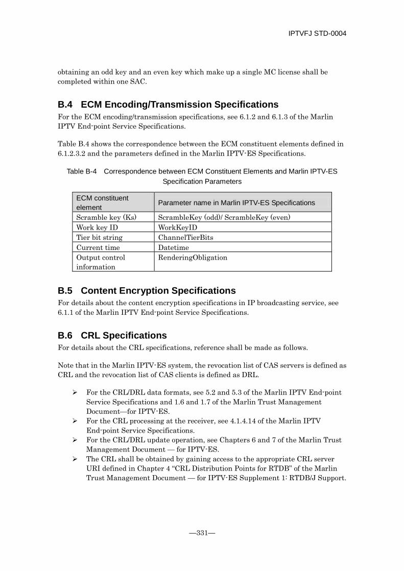
IPTVFJ STD-0004
—331—
obtaining an odd key and an even key which make up a single MC license shall be completed within one SAC.
B.4 ECM Encoding/Transmission Specifications For the ECM encoding/transmission specifications, see 6.1.2 and 6.1.3 of the Marlin IPTV End-point Service Specifications.
Table B.4 shows the correspondence between the ECM constituent elements defined in 6.1.2.3.2 and the parameters defined in the Marlin IPTV-ES Specifications.
Table B-4 Correspondence between ECM Constituent Elements and Marlin IPTV-ES Specification Parameters
ECM constituent element Parameter name in Marlin IPTV-ES Specifications
Scramble key (Ks) ScrambleKey (odd)/ ScrambleKey (even) Work key ID WorkKeyID Tier bit string ChannelTierBits Current time Datetime Output control information
RenderingObligation
B.5 Content Encryption Specifications For details about the content encryption specifications in IP broadcasting service, see 6.1.1 of the Marlin IPTV End-point Service Specifications.
B.6 CRL Specifications For details about the CRL specifications, reference shall be made as follows.
Note that in the Marlin IPTV-ES system, the revocation list of CAS servers is defined as CRL and the revocation list of CAS clients is defined as DRL.
For the CRL/DRL data formats, see 5.2 and 5.3 of the Marlin IPTV End-point Service Specifications and 1.6 and 1.7 of the Marlin Trust Management Document—for IPTV-ES.
For the CRL processing at the receiver, see 4.1.4.14 of the Marlin IPTV End-point Service Specifications.
For the CRL/DRL update operation, see Chapters 6 and 7 of the Marlin Trust Management Document — for IPTV-ES.
The CRL shall be obtained by gaining access to the appropriate CRL server URI defined in Chapter 4 “CRL Distribution Points for RTDB” of the Marlin Trust Management Document — for IPTV-ES Supplement 1: RTDB/J Support.
IPTVFJ STD-0004
-332-
B.7 CAS Server URL Signature Verification Specifications See 4.1.4.12 of the Marlin IPTV-ES/J End-point Service Specifications for the method of signature verification for the CAS server URI used in the setIPTVServiceRegistrationInfo() of the BML that is supposed to be used during the basic registration defined in Chapter 6 “Specifications of BML for IPTV” of IPTVFJ STD-0006 “IPTV Standard: CDN Scope Service Approach Specifications”.
B.8 Trusted Time Specifications Concerning the trusted time, reference shall be made as follows.
For the protocol for obtaining trusted time from the CAS server using a SAC, see 4.2.4.9 and 4.2.4.10 of the Marlin IPTV End-point Service Specifications and 3.2 of the Marlin IPTV-ES Operational Specifications: IP Multicast Volume.
For the operation of trusted time in the CAS processing, see Chapter 3 of the Marlin IPTV-ES/J Specific Compliance Rules: IP Multicast Volume.
When the Get Trusted Time protocol defined in 4.2.2 of the Marlin IPTV End-point Service Specifications is used to obtain trusted time, it is recommended that the time information be obtained together with the license using the Packed Message. However, obtaining time information alone as required is also allowed. In this case, it is desirable from the standpoint of preventing a concentration of load on the server that the time information should be obtained at least 24 hours after the previous time information was obtained.
B.9 CAS/DRM Client Identifier (DRM_ID) The CAS/DRM client identifier (DRM_ID) shall be the value of Subject in the client certificate defined in 5.1.1.4 of the Marlin IPTV End-point Service Specifications and 1.4 of the Marlin Trust Management Document—for IPTV-ES.
B.10 Copy Control and Output Control In the reception/playback of IP broadcast, the control shall be implemented in accordance with the description of output control information (RenderingObligation in the Marlin IPTV-ES system) contained in the ECM. In this case, the copy control and output control shall be done as described in Chapter 2 of the Marlin IPTV-ES/J Specific Compliance Rules: IP Multicast Volume.
B.11 CAS System Name In the CAS system name, ‘marlin_iptv_es’ shall be used as the value of drm_system. In the operation in the CDN scope, said value shall be set as the value of the drm_system that is the argument to the getIPTVLicense() defined in Chapter 6 “Specifications of BML for IPTV” of IPTVFJ STD-0006 “IPTV Standard: CDN Scope Service Approach Specifications”.
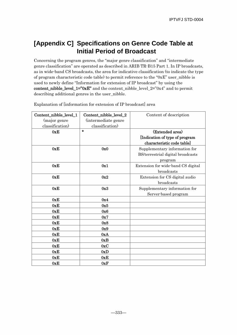
IPTVFJ STD-0004
—333—
[Appendix C] Specifications on Genre Code Table at Initial Period of Broadcast
Concerning the program genres, the “major genre classification” and “intermediate genre classification” are operated as described in ARIB TR-B15 Part 1. In IP broadcasts, as in wide-band CS broadcasts, the area for indicative classification (to indicate the type of program characteristic code table) to permit reference to the “0xE” user_nibble is used to newly define “Information for extension of IP broadcast” by using the content_nibble_level_1=”0xE” and the content_nibble_level_2=”0x4” and to permit describing additional genres in the user_nibble.
Explanation of [information for extension of IP broadcast] area
Content_nibble_level_1 (major genre classification)
Content_nibble_level_2 (intermediate genre
classification)
Content of description
0xE * (Extended area) [Indication of type of program
characteristic code table] 0xE 0x0 Supplementary information for
BS/terrestrial digital broadcasts program
0xE 0x1 Extension for wide-band CS digital broadcasts
0xE 0x2 Extension for CS digital audio broadcasts
0xE 0x3 Supplementary information for Server-based program
0xE 0x4
0xE 0x5
0xE 0x6
0xE 0x7
0xE 0x8
0xE 0x9
0xE 0xA
0xE 0xB
0xE 0xC
0xE 0xD
0xE 0xE
0xE 0xF

IPTVFJ STD-0004
-334-
Upper 4 bits of
user_nibble Lower 4 bits of
user_nibble Content of description
0x0 * Sports 0x0 0x0 Tennis 0x0 0x1 Basketball 0x0 0x2 Rugby 0x0 0x3 American football 0x0 0x4 Boxing 0x0 0x5 Professional wrestling 0x0 0x6
0x0 0x7 0x0 0x8
0x0 0x9
0x0 0xA
0x0 0xB
0x0 0xC
0x0 0xD
0x0 0xE
0x0 0xF Other
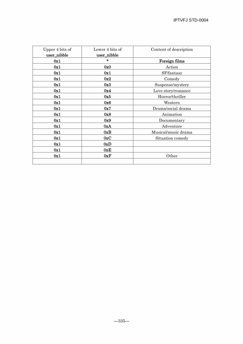
IPTVFJ STD-0004
—335—
Upper 4 bits of
user_nibble Lower 4 bits of
user_nibble Content of description
0x1 * Foreign films 0x1 0x0 Action 0x1 0x1 SF/fantasy 0x1 0x2 Comedy 0x1 0x3 Suspense/mystery 0x1 0x4 Love story/romance 0x1 0x5 Horror/thriller 0x1 0x6 Western 0x1 0x7 Drama/social drama 0x1 0x8 Animation 0x1 0x9 Documentary 0x1 0xA Adventure 0x1 0xB Musical/music drama 0x1 0xC Situation comedy 0x1 0xD
0x1 0xE
0x1 0xF Other
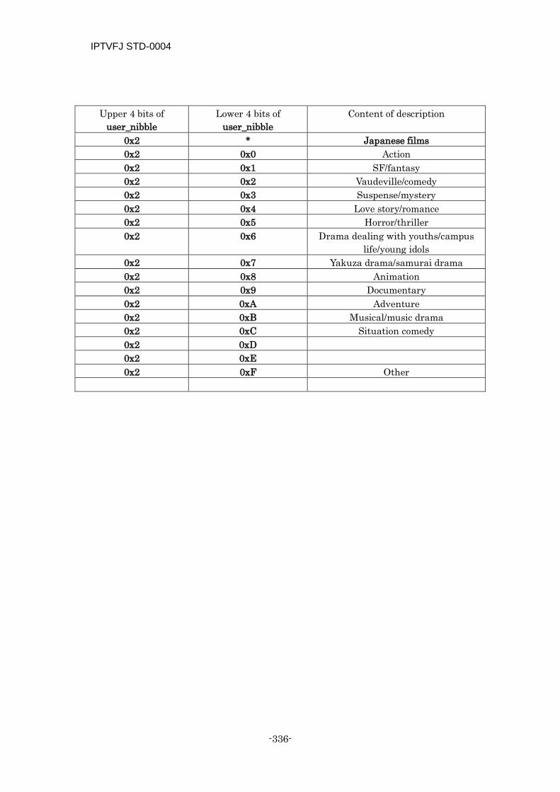
IPTVFJ STD-0004
-336-
Upper 4 bits of
user_nibble Lower 4 bits of
user_nibble Content of description
0x2 * Japanese films 0x2 0x0 Action 0x2 0x1 SF/fantasy 0x2 0x2 Vaudeville/comedy 0x2 0x3 Suspense/mystery 0x2 0x4 Love story/romance 0x2 0x5 Horror/thriller 0x2 0x6 Drama dealing with youths/campus
life/young idols 0x2 0x7 Yakuza drama/samurai drama 0x2 0x8 Animation 0x2 0x9 Documentary 0x2 0xA Adventure 0x2 0xB Musical/music drama 0x2 0xC Situation comedy 0x2 0xD
0x2 0xE
0x2 0xF Other
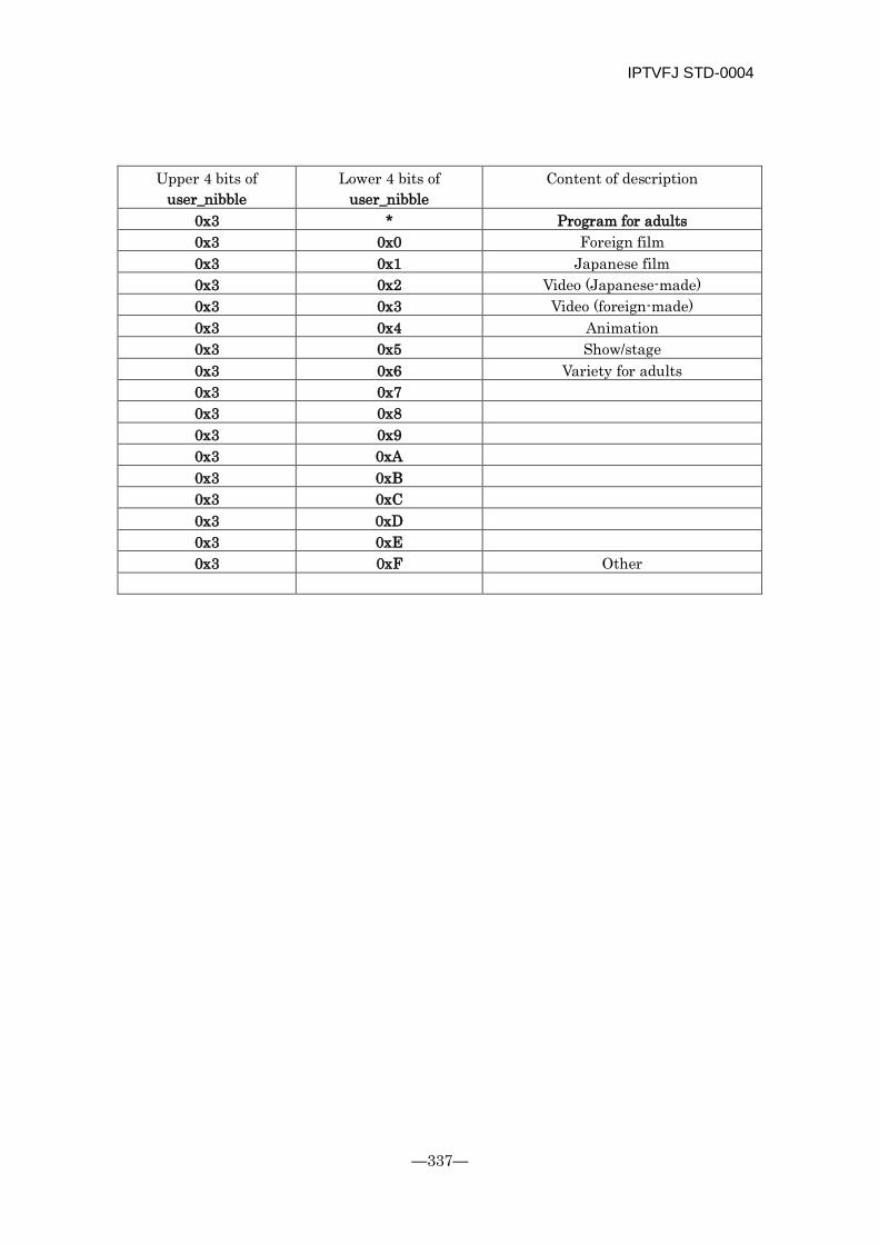
IPTVFJ STD-0004
—337—
Upper 4 bits of
user_nibble Lower 4 bits of
user_nibble Content of description
0x3 * Program for adults 0x3 0x0 Foreign film
0x3 0x1 Japanese film
0x3 0x2 Video (Japanese-made) 0x3 0x3 Video (foreign-made) 0x3 0x4 Animation 0x3 0x5 Show/stage 0x3 0x6 Variety for adults 0x3 0x7
0x3 0x8
0x3 0x9
0x3 0xA
0x3 0xB
0x3 0xC
0x3 0xD
0x3 0xE
0x3 0xF Other
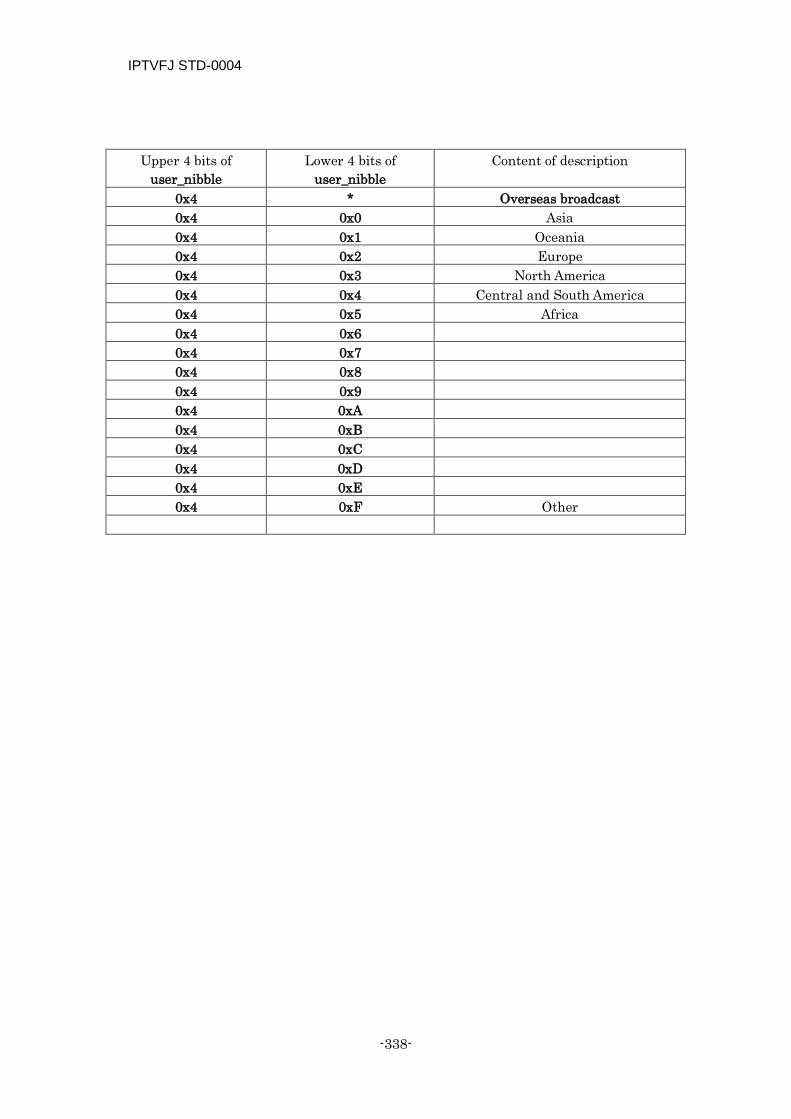
IPTVFJ STD-0004
-338-
Upper 4 bits of
user_nibble Lower 4 bits of
user_nibble Content of description
0x4 * Overseas broadcast 0x4 0x0 Asia 0x4 0x1 Oceania 0x4 0x2 Europe 0x4 0x3 North America 0x4 0x4 Central and South America 0x4 0x5 Africa 0x4 0x6
0x4 0x7
0x4 0x8
0x4 0x9
0x4 0xA
0x4 0xB
0x4 0xC
0x4 0xD
0x4 0xE
0x4 0xF Other
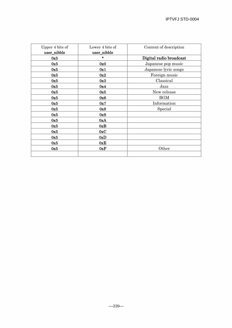
IPTVFJ STD-0004
—339—
Upper 4 bits of
user_nibble Lower 4 bits of
user_nibble Content of description
0x5 * Digital radio broadcast 0x5 0x0 Japanese pop music 0x5 0x1 Japanese lyric songs 0x5 0x2 Foreign music 0x5 0x3 Classical 0x5 0x4 Jazz 0x5 0x5 New release 0x5 0x6 BGM
0x5 0x7 Information 0x5 0x8 Special 0x5 0x9
0x5 0xA
0x5 0xB
0x5 0xC
0x5 0xD
0x5 0xE
0x5 0xF Other
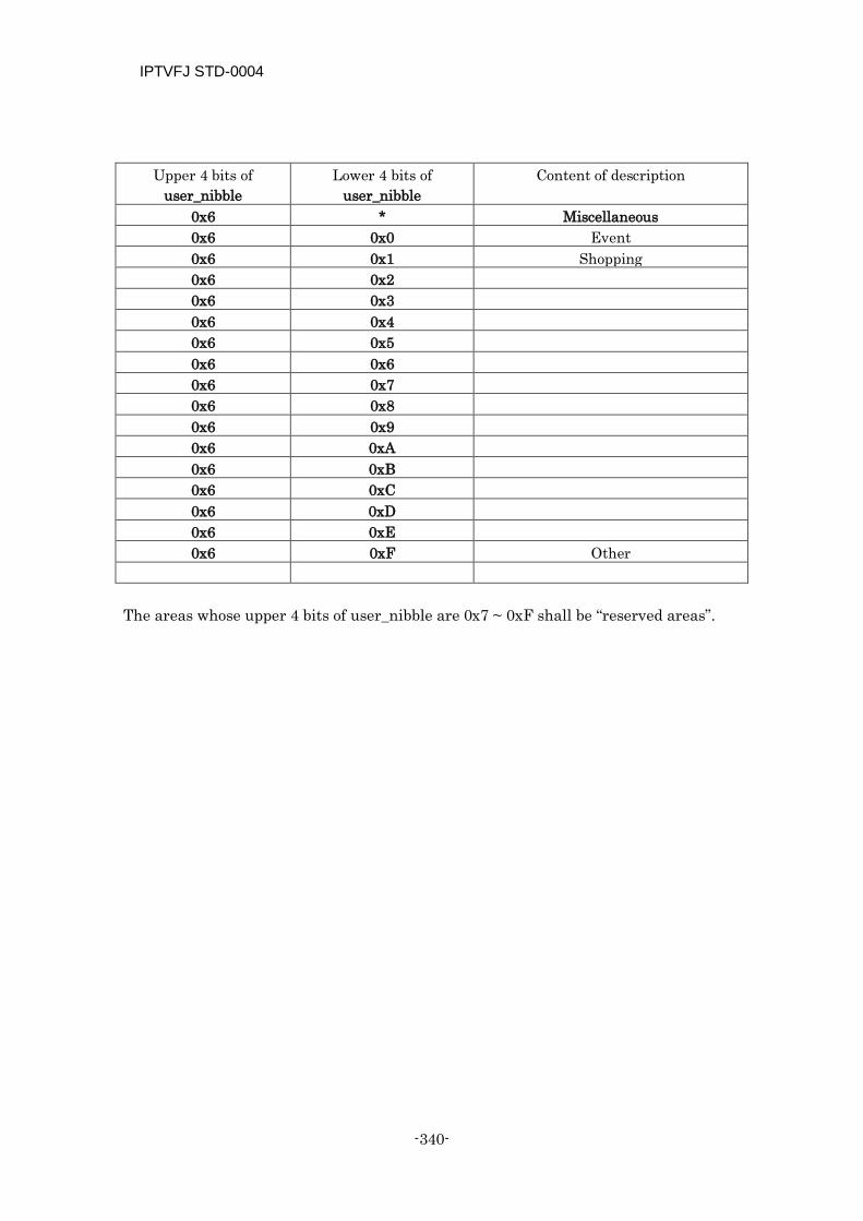
IPTVFJ STD-0004
-340-
Upper 4 bits of
user_nibble Lower 4 bits of
user_nibble Content of description
0x6 * Miscellaneous 0x6 0x0 Event 0x6 0x1 Shopping 0x6 0x2
0x6 0x3
0x6 0x4
0x6 0x5
0x6 0x6
0x6 0x7
0x6 0x8
0x6 0x9
0x6 0xA
0x6 0xB
0x6 0xC
0x6 0xD
0x6 0xE
0x6 0xF Other
The areas whose upper 4 bits of user_nibble are 0x7 ~ 0xF shall be “reserved areas”.
IPTVFJ STD-0004
—341—
C.1 Presupposed Operation In IP broadcasts, as in wide-band CS broadcasts, the channels are more specialized than those used in BS digital broadcasts. Therefore, in consideration of the user’s convenience, it was decided that the user_nibble that has been newly added should transmit program genres which are subdivided more minutely.
The information for IP broadcast extension shall be used only in IP broadcasts.
Taking into consideration the presence of receivers which support only program retrieval at the intermediate classification level, the basic operation of the user_nibble shall be as follows.
In addition to the information for IP broadcast extension, the information belonging to the appropriate major and intermediate classifications that is considered the most suitable shall be described as much as possible.
In the case of a “Japanese-made animation film”, for example, describe the following two items:
Content_nibble_level_1=0x6, Content_nibble_level_2=0x2, user_nibble=0xFF
Content_nibble_level_1=0xE, Content_nibble_level_2=0x4, user_nibble=0x28
Note, however, for any program that is broadcast as a video service for adults (service_type = “0x80”), the program information must not be described in the user_nibble of which the upper 4 bits are other than “0x3” priventing the information should be displayed by mistake as a result of program retrieval, etc.
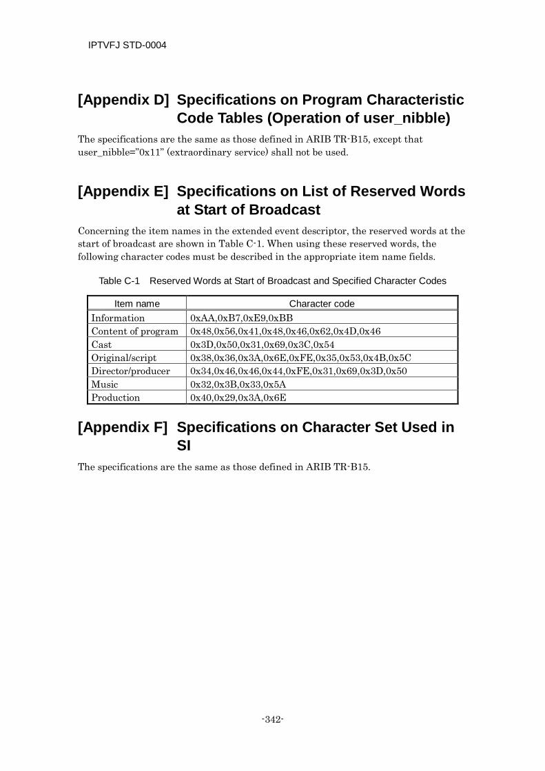
IPTVFJ STD-0004
-342-
[Appendix D] Specifications on Program Characteristic Code Tables (Operation of user_nibble)
The specifications are the same as those defined in ARIB TR-B15, except that user_nibble=”0x11” (extraordinary service) shall not be used.
[Appendix E] Specifications on List of Reserved Words
at Start of Broadcast Concerning the item names in the extended event descriptor, the reserved words at the start of broadcast are shown in Table C-1. When using these reserved words, the following character codes must be described in the appropriate item name fields.
Table C-1 Reserved Words at Start of Broadcast and Specified Character Codes
Item name Character code Information 0xAA,0xB7,0xE9,0xBB Content of program 0x48,0x56,0x41,0x48,0x46,0x62,0x4D,0x46 Cast 0x3D,0x50,0x31,0x69,0x3C,0x54 Original/script 0x38,0x36,0x3A,0x6E,0xFE,0x35,0x53,0x4B,0x5C Director/producer 0x34,0x46,0x46,0x44,0xFE,0x31,0x69,0x3D,0x50 Music 0x32,0x3B,0x33,0x5A Production 0x40,0x29,0x3A,0x6E
[Appendix F] Specifications on Character Set Used in
SI The specifications are the same as those defined in ARIB TR-B15.
IPTVFJ STD-0004
—343—
[Appendix G] Specifications: Unified Operation and Display
On operation
In the event_name_char that is transmitted by an EIT short event descriptor, the program title and program caption shall be described as the program name.
The program name shall not exceed 40 double-byte characters (80 bytes) in length.
For a 30-minute or shorter program, the program name shall, as a rule, be 20 characters or less in length.
A brief explanation of the content of a program shall be described in program description text_char.
The program description shall not exceed 80 double-byte characters (160 bytes) in length.
Line Feed shall not be used in the program name or series name series_name_char.
The series descriptor shall be operated as described in the PSI/SI Operation Specification. Therefore, there are cases in which the program name and the series name are the same.
Special symbols, such as N, 天, 字 and 二, might be used in a program name and series name. The description of those symbols is left to the judgment of each individual service provider. Therefore, when some special symbol is used as a key for retrieval of a certain program attribute, it is not always possible to extract the programs having said attribute from all broadcasting stations. For this purpose, it is better to use the relevant information supplied by some suitable descriptor.
The method of giving a program name (title and caption) and the content of program description are left to the judgment of each individual service provider. Therefore, they might contain some information that is not directly related to the program.
On display
The “program name” shall be displayed as precisely as possible.
If the program name cannot completely be displayed on one screen, some suitable notation (e.g., “…”) shall be used to indicate to the viewer that there is a continuation to the program name.
It is desirable that “program description” should be displayed following the “program name”.

IPTVFJ STD-0004
-344-
[Appendix H] Explanation: Operation Relating to CAS
H.1 Operation of Work Keys and Tier Bits The operation of the work keys (Kw) that are delivered as constituent elements of the MC license in IP broadcasting service and the operation of the tier bits that accompany the work keys are explained below.
The work keys are always delivered in pairs—an odd work key and an even work key. They are managed in the CAS client. An example of work key update operation is shown in Fig. H-1. The work key for encrypting an ECM shall continue to be used for a certain period of time. However, it shall be updated at certain intervals of time or when some security problem has arisen. The work keys shall be updated in this order: even work key odd work key even work key odd work key. Whenever an MC license is to be acquired, the work key that is currently used to encrypt the ECM and the work key for the next updating shall be obtained in pairs. Ordinarily, the MC license is updated at the time when the contract is renewed. However, there is no need to update the work keys each time the MC license is updated. On the other hand, in an emergency in which a security problem has occurred, it might become necessary to update the work keys regardless of the timing of contract renewal and acquire an MC license containing a new work key pair.
Each provider of IP broadcasting service can simultaneously operate the maximum number of work key pairs that form the time series of work keys described above. The work key ID contained in the MC license identifies the work key pair. The work key pair identification information is also contained in the license ID.
Figure H-1 Example of Work Key Updating Operation
Kw even1 Kw odd2 Kw even3 Kw odd4
Kw even1 Kw odd2
Kw even1 Kw odd2
Kw even3 Kw odd2
Kw even3 Kw odd2
Kw even3 Kw odd4
Kw even5 Kw odd4
Kw even5 Kw odd4
t
MC license acquisition timing
Operated work key
At time of contract
It is not always necessary to update the Kw when acquiring a new MC license at the time of contract renewal.
A case in which it is necessary to update the Kw when acquiring a new MC at the time of contract renewal
A case in which the Kw is updated in an emergency, such as the occurrence of a security problem with Kw even3 in this particular example
At time of contract renewal
At time of contract renewal
At time of contract renewal
At time of contract renewal
At time of key updating
At time of contract renewal
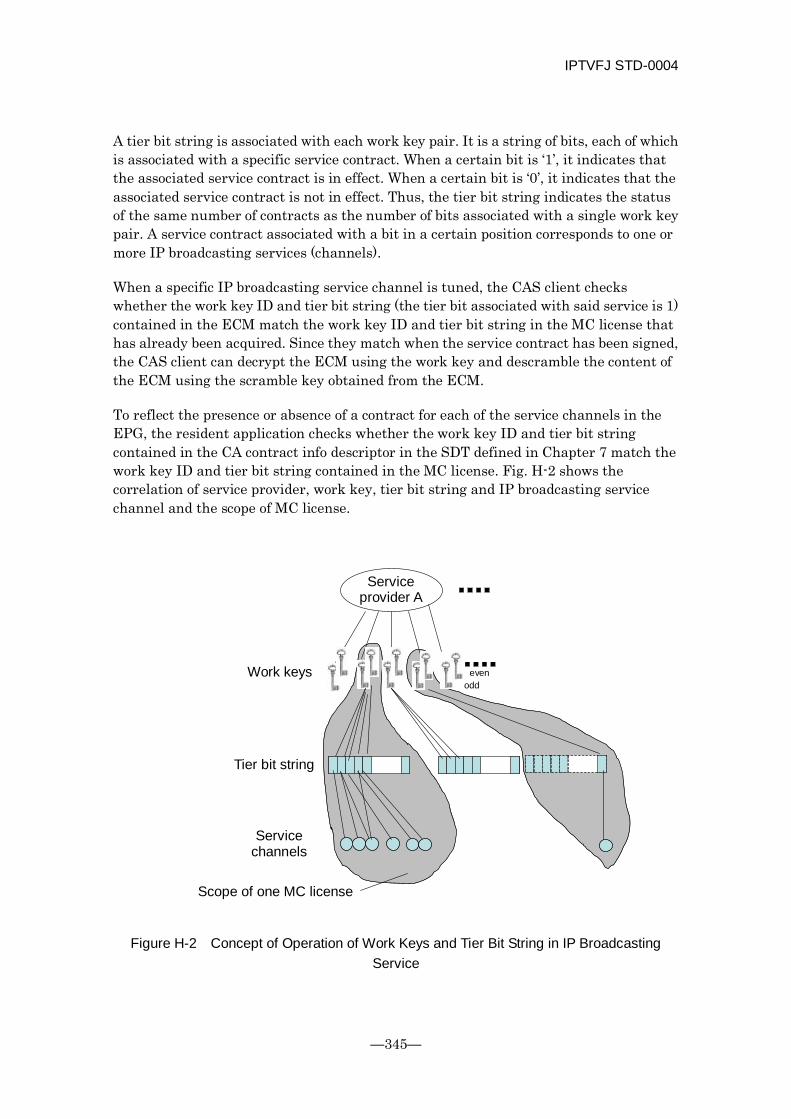
IPTVFJ STD-0004
—345—
A tier bit string is associated with each work key pair. It is a string of bits, each of which is associated with a specific service contract. When a certain bit is ‘1’, it indicates that the associated service contract is in effect. When a certain bit is ‘0’, it indicates that the associated service contract is not in effect. Thus, the tier bit string indicates the status of the same number of contracts as the number of bits associated with a single work key pair. A service contract associated with a bit in a certain position corresponds to one or more IP broadcasting services (channels).
When a specific IP broadcasting service channel is tuned, the CAS client checks whether the work key ID and tier bit string (the tier bit associated with said service is 1) contained in the ECM match the work key ID and tier bit string in the MC license that has already been acquired. Since they match when the service contract has been signed, the CAS client can decrypt the ECM using the work key and descramble the content of the ECM using the scramble key obtained from the ECM.
To reflect the presence or absence of a contract for each of the service channels in the EPG, the resident application checks whether the work key ID and tier bit string contained in the CA contract info descriptor in the SDT defined in Chapter 7 match the work key ID and tier bit string contained in the MC license. Fig. H-2 shows the correlation of service provider, work key, tier bit string and IP broadcasting service channel and the scope of MC license.
Figure H-2 Concept of Operation of Work Keys and Tier Bit String in IP Broadcasting Service
even odd
Service provider A
Work keys
Tier bit string
Service channels
Scope of one MC license
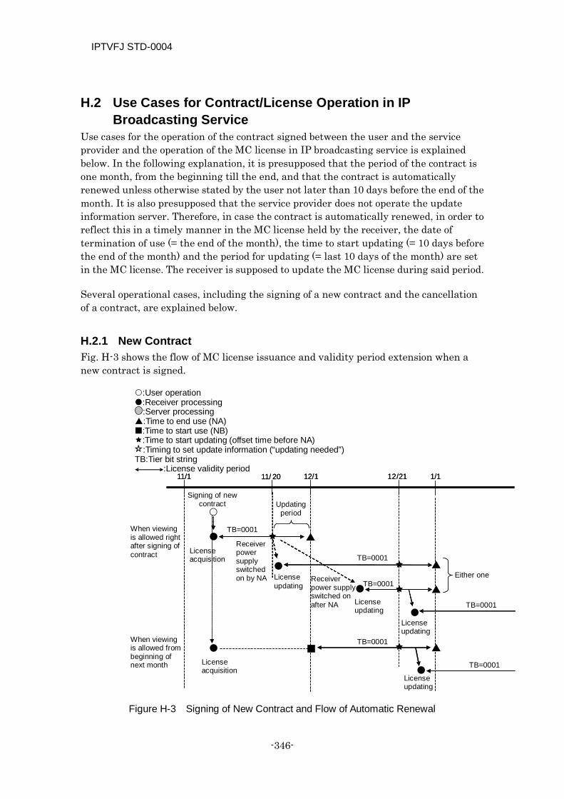
IPTVFJ STD-0004
-346-
H.2 Use Cases for Contract/License Operation in IP Broadcasting Service
Use cases for the operation of the contract signed between the user and the service provider and the operation of the MC license in IP broadcasting service is explained below. In the following explanation, it is presupposed that the period of the contract is one month, from the beginning till the end, and that the contract is automatically renewed unless otherwise stated by the user not later than 10 days before the end of the month. It is also presupposed that the service provider does not operate the update information server. Therefore, in case the contract is automatically renewed, in order to reflect this in a timely manner in the MC license held by the receiver, the date of termination of use (= the end of the month), the time to start updating (= 10 days before the end of the month) and the period for updating (= last 10 days of the month) are set in the MC license. The receiver is supposed to update the MC license during said period.
Several operational cases, including the signing of a new contract and the cancellation of a contract, are explained below.
H.2.1 New Contract Fig. H-3 shows the flow of MC license issuance and validity period extension when a new contract is signed.
Figure H-3 Signing of New Contract and Flow of Automatic Renewal
11/1 12/1 1/1
TB=0001
TB=0001
TB=0001
TB=0001
TB=0001
11/ 20 1 2 / 21 11/1 12/1 1/1
TB=0001
11/ 20 1 2 / 21
Signing of new contract Updating
period
License acquisition
License acquisition
Receiver power supply switched on by NA License
updating
License updating
License updating
License updating
Receiver power supply switched on after NA
Either one
When viewing is allowed right after signing of contract
When viewing is allowed from beginning of next month
:User operation :Receiver processing :Server processing :Time to end use (NA) :Time to start use (NB) :Time to start updating (offset time before NA)
:Timing to set update information (“updating needed”) TB:Tier bit string
:License validity period
IPTVFJ STD-0004
—347—
In this example, by manipulating the remote controller of the receiver, the user gains access to the portal of the service provider, selects the desired package from the IP broadcasting service list on the service subscription page, subscribes to the selected package and obtains the MC license through the receiver at the beginning of November. In this process, if the service provider wants the user to start viewing the package right after the signing of the contract, the service provider issues an MC license in which the time to start the use thereof (NB) is not fixed but the time to end the use thereof (NA) is fixed for the end of November and the time to start updating the license is fixed for November 20 — 10 days before the end of the month. If the service provider wants the user to start viewing the package from the next month, it issues an MC license in which the time to start the use thereof is fixed for December 1, the time to end the use thereof is fixed for the end of December and the time to start updating the license is fixed for December 21—10 days before the end of the month.
When the clock managed by the receiver indicates that the time to start updating the license has come, the receiver obtains from the CAS server a new license that has an extended term of validity at an opportune moment (e.g., when the receiver’s power supply is switched on). It can happen that the time to end the use of the license passes before the license is updated. This does happen, for example, when the receiver’s power supply is not switched on during the updating period. In this case, when the power supply is switched on at some later time, a new license might be obtained before the use of the service is started.
In this example, the tier bit string (TB) remains unchanged from 0001 since the only operation that is performed is extending the license validity term.
H.2.2 Partial Cancellation of Service (Change of Tier Bit String) Fig. H-4 shows the license updating flow when a channel associated with a tier is canceled.
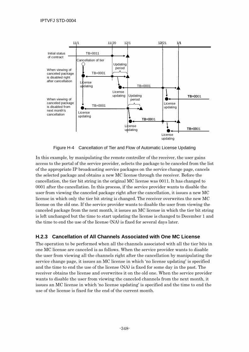
IPTVFJ STD-0004
-348-
Figure H-4 Cancellation of Tier and Flow of Automatic License Updating
In this example, by manipulating the remote controller of the receiver, the user gains access to the portal of the service provider, selects the package to be canceled from the list of the appropriate IP broadcasting service packages on the service change page, cancels the selected package and obtains a new MC license through the receiver. Before the cancellation, the tier bit string in the original MC license was 0011. It has changed to 0001 after the cancellation. In this process, if the service provider wants to disable the user from viewing the canceled package right after the cancellation, it issues a new MC license in which only the tier bit string is changed. The receiver overwrites the new MC license on the old one. If the service provider wants to disable the user from viewing the canceled package from the next month, it issues an MC license in which the tier bit string is left unchanged but the time to start updating the license is changed to December 1 and the time to end the use of the license (NA) is fixed for several days later.
H.2.3 Cancellation of All Channels Associated with One MC License The operation to be performed when all the channels associated with all the tier bits in one MC license are canceled is as follows. When the service provider wants to disable the user from viewing all the channels right after the cancellation by manipulating the service change page, it issues an MC license in which ‘no license updating’ is specified and the time to end the use of the license (NA) is fixed for some day in the past. The receiver obtains the license and overwrites it on the old one. When the service provider wants to disable the user from viewing the canceled channels from the next month, it issues an MC license in which ‘no license updating’ is specified and the time to end the use of the license is fixed for the end of the current month.
TB=0011
TB=0001
TB=0001
TB=00
11/1 12/1 1/1 11/ 20
TB=00
TB=00
TB=0001
1 2 / 21
TB=0001
1/1
TB=0001
TB=0001
1 2 /
Initial status of contract
Cancellation of tier Updating
period When viewing of canceled package is disabled right after cancellation License
updating
License updating
License updating
License updating
License updating
License updating
Updating period When viewing of
canceled package is disabled from next month’s cancellation
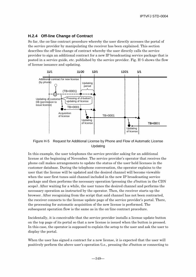
IPTVFJ STD-0004
—349—
H.2.4 Off-line Change of Contract So far, the on-line contract procedure whereby the user directly accesses the portal of the service provider by manipulating the receiver has been explained. This section describes the off-line change of contract whereby the user directly calls the service provider to sign an additional contract for a new IP broadcasting service package that is posted in a service guide, etc. published by the service provider. Fig. H-5 shows the flow of license issuance and updating.
Figure H-5 Request for Additional License by Phone and Flow of Automatic License Updating
In this example, the user telephones the service provider asking for an additional license at the beginning of November. The service provider’s operator that receives the phone call makes arrangements to update the status of the user-held licenses in the customer database. During the telephone conversation, the operator explains to the user that the license will be updated and the desired channel will become viewable when the user first tunes said channel included in the new IP broadcasting service package and then performs the necessary operation (pressing the d button in the CDN scope). After waiting for a while, the user tunes the desired channel and performs the necessary operation as instructed by the operator. Then, the receiver starts up the browser. After recognizing from the script that said channel has not been contracted, the receiver connects to the license update page of the service provider’s portal. There, the processing for automatic acquisition of the new license is performed. The subsequent operation flow is the same as in the on-line contract procedure.
Incidentally, it is conceivable that the service provider installs a license update button on the top page of its portal so that a new license is issued when the button is pressed. In this case, the operator is supposed to explain the setup to the user and ask the user to display the portal.
When the user has signed a contract for a new license, it is expected that the user will positively perform the above user’s operation (i.e., pressing the d button or connecting to
11/1 12/1 1/1 11/ 20
TB=0001
TB=00
TB=0001
1 2 / 21 11/1 12/1 1/1 11/ 20 11/1 12/1 1/1 11/ 20
(TB=0001)
TB=0001
1 2 / 21
Updating of license
Updating of license
Acquisition of license
Updating period
Updating of customer DB (permission to issue license)
Additional contract for new license (by phone)
Pressing of d-button/ updating of license
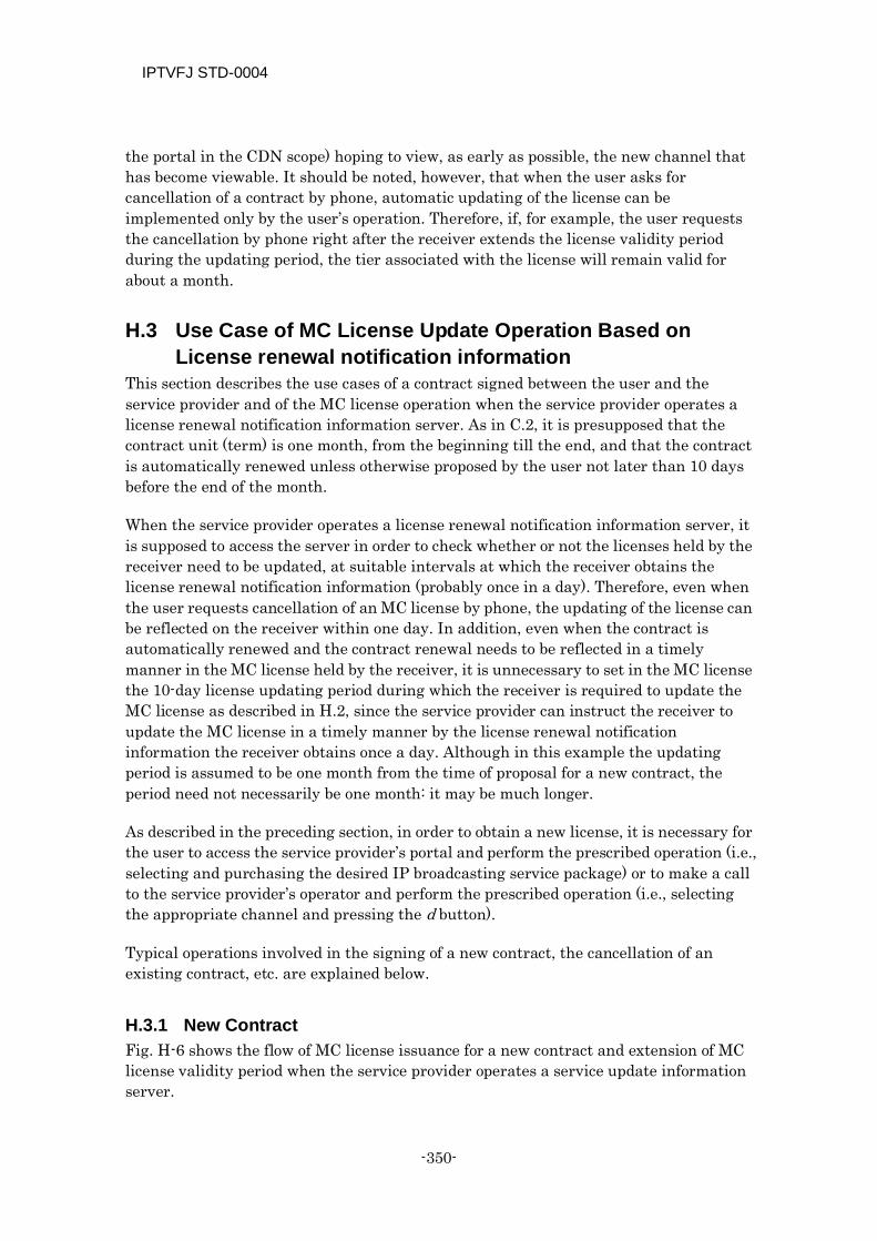
IPTVFJ STD-0004
-350-
the portal in the CDN scope) hoping to view, as early as possible, the new channel that has become viewable. It should be noted, however, that when the user asks for cancellation of a contract by phone, automatic updating of the license can be implemented only by the user’s operation. Therefore, if, for example, the user requests the cancellation by phone right after the receiver extends the license validity period during the updating period, the tier associated with the license will remain valid for about a month.
H.3 Use Case of MC License Update Operation Based on License renewal notification information
This section describes the use cases of a contract signed between the user and the service provider and of the MC license operation when the service provider operates a license renewal notification information server. As in C.2, it is presupposed that the contract unit (term) is one month, from the beginning till the end, and that the contract is automatically renewed unless otherwise proposed by the user not later than 10 days before the end of the month.
When the service provider operates a license renewal notification information server, it is supposed to access the server in order to check whether or not the licenses held by the receiver need to be updated, at suitable intervals at which the receiver obtains the license renewal notification information (probably once in a day). Therefore, even when the user requests cancellation of an MC license by phone, the updating of the license can be reflected on the receiver within one day. In addition, even when the contract is automatically renewed and the contract renewal needs to be reflected in a timely manner in the MC license held by the receiver, it is unnecessary to set in the MC license the 10-day license updating period during which the receiver is required to update the MC license as described in H.2, since the service provider can instruct the receiver to update the MC license in a timely manner by the license renewal notification information the receiver obtains once a day. Although in this example the updating period is assumed to be one month from the time of proposal for a new contract, the period need not necessarily be one month: it may be much longer.
As described in the preceding section, in order to obtain a new license, it is necessary for the user to access the service provider’s portal and perform the prescribed operation (i.e., selecting and purchasing the desired IP broadcasting service package) or to make a call to the service provider’s operator and perform the prescribed operation (i.e., selecting the appropriate channel and pressing the d button).
Typical operations involved in the signing of a new contract, the cancellation of an existing contract, etc. are explained below.
H.3.1 New Contract Fig. H-6 shows the flow of MC license issuance for a new contract and extension of MC license validity period when the service provider operates a service update information server.
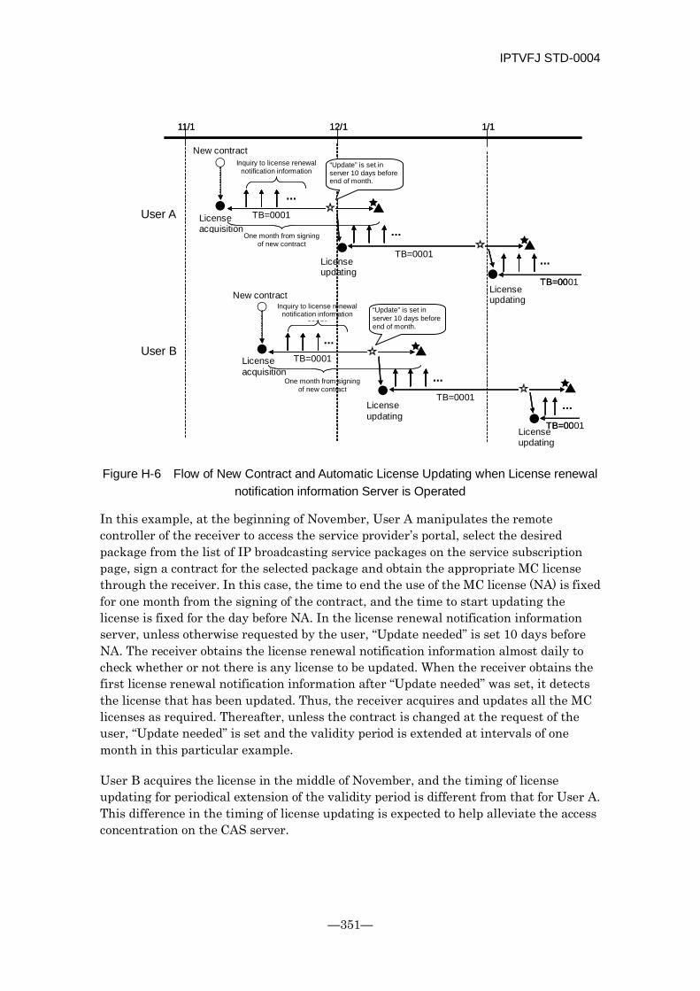
IPTVFJ STD-0004
—351—
Figure H-6 Flow of New Contract and Automatic License Updating when License renewal notification information Server is Operated
In this example, at the beginning of November, User A manipulates the remote controller of the receiver to access the service provider’s portal, select the desired package from the list of IP broadcasting service packages on the service subscription page, sign a contract for the selected package and obtain the appropriate MC license through the receiver. In this case, the time to end the use of the MC license (NA) is fixed for one month from the signing of the contract, and the time to start updating the license is fixed for the day before NA. In the license renewal notification information server, unless otherwise requested by the user, “Update needed” is set 10 days before NA. The receiver obtains the license renewal notification information almost daily to check whether or not there is any license to be updated. When the receiver obtains the first license renewal notification information after “Update needed” was set, it detects the license that has been updated. Thus, the receiver acquires and updates all the MC licenses as required. Thereafter, unless the contract is changed at the request of the user, “Update needed” is set and the validity period is extended at intervals of one month in this particular example.
User B acquires the license in the middle of November, and the timing of license updating for periodical extension of the validity period is different from that for User A. This difference in the timing of license updating is expected to help alleviate the access concentration on the CAS server.
11/1 12/1 1/1
TB=0001
TB=00
TB=0001
TB=0001
TB=00
11/1 12/1 1/1
TB=0001 ...
TB=0001
TB=0001
User A
User B
New contract
License acquisition
New contract
License acquisition
License updating
License updating
License updating
One month from signing of new contract
One month from signing of new contract
Inquiry to license renewal notification information
Inquiry to license renewal notification information
server
License updating
...
...
...
...
...
“Update” is set in server 10 days before end of month.
“Update” is set in server 10 days before end of month.
IPTVFJ STD-0004
-352-
H.3.2 Partial Cancellation (Change of Tier Bit String) Fig. H-7 shows the flow of license updating when the user cancels by phone a channel associated with a certain tier while the license renewal notification information server is in operation.
Figure H-7 Cancellation of Tier by Phone and Flow of License Updating when License renewal notification information Server is Operated
In this example, the user requests cancellation of a tier by phone at the beginning of November. Then, the status of the user’s licenses in the customer database is updated without delay and “Update needed” is set in the license renewal notification information server by the operation of the service provider’s operator who receives the phone. Since the receiver obtains license renewal notification information almost daily, a new license in which the tier bit string is changed from 0011 to 0001 as a result of the channel cancellation is issued at the time of the access made right after “Update needed” is set. The receiver obtains the new license and overwrites it on the old license. In this example, the operator is required only to explain to the user that the result of the cancellation will be reflected in the new license in about one day. However, if the service provider does not want to reflect the result of the tier cancellation before the end of the month, it sets “Update needed” in the license renewal notification information server at the end of the month.
TB=0011
TB=0001
TB=0001
TB=0001
TB=0011
11/1 12/1 1/1
...
Initial contract status
Tier cancellation (by phone)
Inquiry to license renewal notification information
server
“Update needed” is set in server.
License updating
License updating
License updating
...
...
...
IPTVFJ STD-0004
—353—
[Appendix I] Explanation: Estimation of Amount of Information in Commonly Operated SI
In IP broadcasts, the SI is independently operated in each individual network. Besides, the ordinary TS and the SI-exclusive TS use different types of tables to transmit programs.
Each of the ordinary TSes transmits the following tables:
NIT
BIT
SDT[actual]
EIT[p/f actual]
Each of the SI-exclusive TS transmits the following tables:
NIT
BIT
SDT[other]
EIT[schedule other]
An estimated amount of information contained in each of the above tables is shown below.
In IP broadcasts, as in wide-band CS digital broadcasts, many services are operated. Therefore, it is appropriate to take into account the increase (decrease) in the volume of SI information due to a change in the numbers of services and programs.
I.1 Presuppositions The conditions that were used in estimating the amounts of information are shown below. Many of them are mere suppositions: they do not represent the conditions that must be used in actual operations. No limitation is set on the total amount of information based on the maximum amount of information for each item.
It should be noted that the estimated figures are basically realistic ones that do not leave unnecessarily large margins.
Number of TSes per network :100 Number of services (TV services only) contained in each TS :1 Number of programs per service per day :40 Number of programs per service per segment :5 Program name length of each program :80 bytes Program description length of each program :160 bytes Item name length of each program :16 bytes Item description length of each program :600 bytes
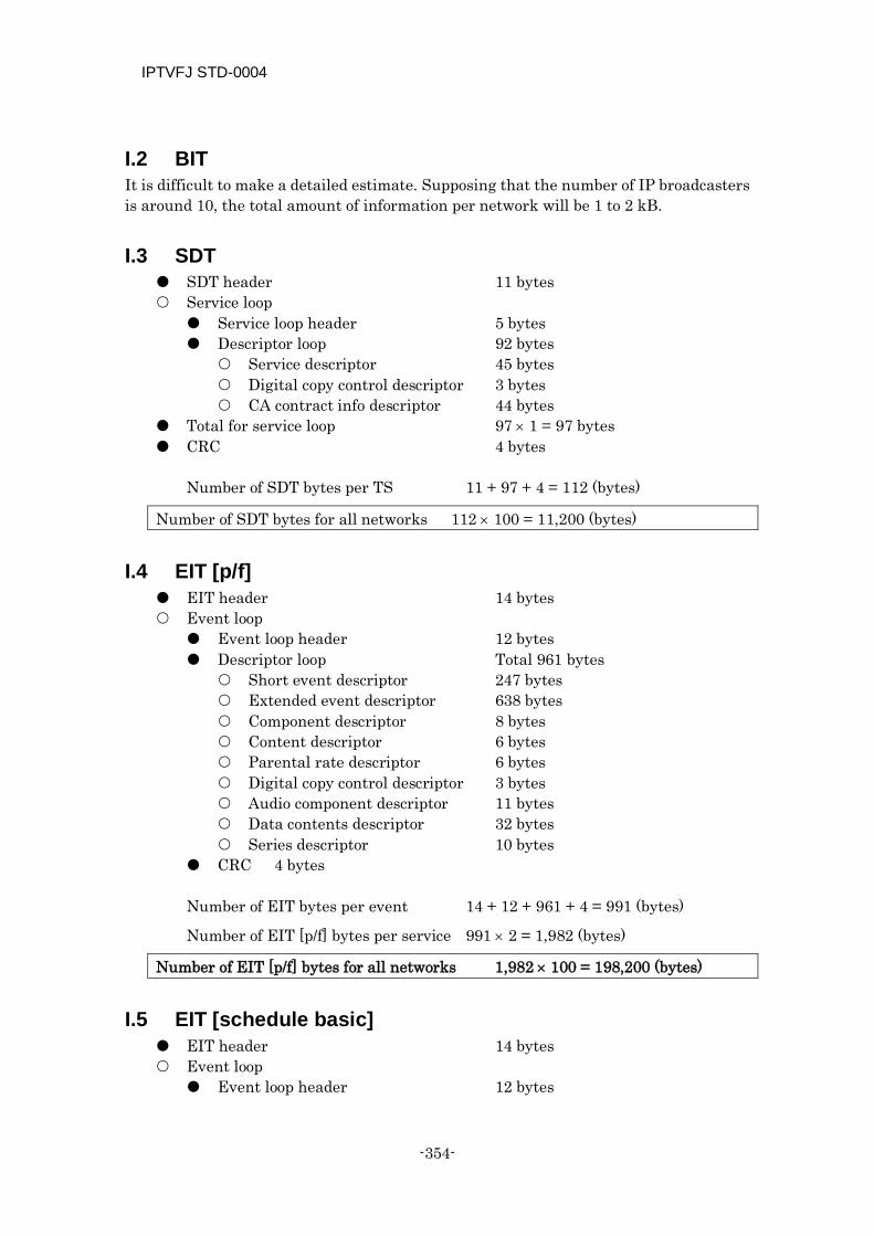
IPTVFJ STD-0004
-354-
I.2 BIT It is difficult to make a detailed estimate. Supposing that the number of IP broadcasters is around 10, the total amount of information per network will be 1 to 2 kB.
I.3 SDT SDT header 11 bytes Service loop Service loop header 5 bytes Descriptor loop 92 bytes Service descriptor 45 bytes Digital copy control descriptor 3 bytes CA contract info descriptor 44 bytes
Total for service loop 97 × 1 = 97 bytes CRC 4 bytes
Number of SDT bytes per TS 11 + 97 + 4 = 112 (bytes)
Number of SDT bytes for all networks 112 × 100 = 11,200 (bytes)
I.4 EIT [p/f] EIT header 14 bytes Event loop Event loop header 12 bytes Descriptor loop Total 961 bytes
Short event descriptor 247 bytes Extended event descriptor 638 bytes Component descriptor 8 bytes Content descriptor 6 bytes Parental rate descriptor 6 bytes Digital copy control descriptor 3 bytes Audio component descriptor 11 bytes Data contents descriptor 32 bytes Series descriptor 10 bytes
CRC 4 bytes
Number of EIT bytes per event 14 + 12 + 961 + 4 = 991 (bytes)
Number of EIT [p/f] bytes per service 991 × 2 = 1,982 (bytes)
Number of EIT [p/f] bytes for all networks 1,982 × 100 = 198,200 (bytes)
I.5 EIT [schedule basic] EIT header 14 bytes Event loop Event loop header 12 bytes
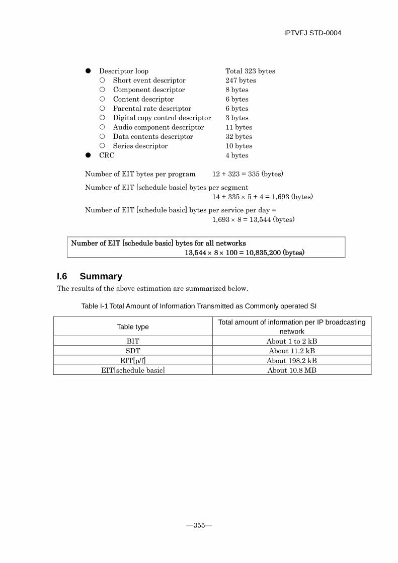
IPTVFJ STD-0004
—355—
Descriptor loop Total 323 bytes Short event descriptor 247 bytes Component descriptor 8 bytes Content descriptor 6 bytes Parental rate descriptor 6 bytes Digital copy control descriptor 3 bytes Audio component descriptor 11 bytes Data contents descriptor 32 bytes Series descriptor 10 bytes
CRC 4 bytes
Number of EIT bytes per program 12 + 323 = 335 (bytes)
Number of EIT [schedule basic] bytes per segment 14 + 335 × 5 + 4 = 1,693 (bytes)
Number of EIT [schedule basic] bytes per service per day = 1,693 × 8 = 13,544 (bytes)
Number of EIT [schedule basic] bytes for all networks
13,544 × 8 × 100 = 10,835,200 (bytes)
I.6 Summary The results of the above estimation are summarized below.
Table I-1 Total Amount of Information Transmitted as Commonly operated SI
Table type Total amount of information per IP broadcasting network
BIT About 1 to 2 kB SDT About 11.2 kB
EIT[p/f] About 198.2 kB EIT[schedule basic] About 10.8 MB

IPTVFJ STD-0004
-356-
References (PSI/SI Receiver Guidelines) The PSI/SI receiver guidelines relating to IP broadcast receivers are basically the same as those described in ARIB TR-B15. For details of the PSI/SI receiver guidelines, see the appropriate chapters.
IPTVFJ STD-0004
—357—
IPTV Standard
IP Broadcasting Specifications IPTVFJ STD-0004 Version 1.2
September 11, 2008 Version 0.9 issued December 8, 2008 Version 1.1 issued August 6, 2010 Version 1.2 issued
IPTV Forum Japan
3F, Futaba Akasaka Bldg.,
8-5-43, Akasaka, Minato-ku, Tokyo 107-0052, Japan Phone: 03-5858-6685 Fax: 03-5858-6675
e-mail: [email protected]


![AP3150 Multichannel IP Voice Broadcasting Server [호환 모드] Adi Cd f APMP3 2M d l AP3150 Multichannel IP Voice Broadcasting Server APOS Service Features • Voice Codec for AP-AUDIO4](https://static.fdocuments.net/doc/165x107/610556d5f397a435bc5b554a/ap3150-multichannel-ip-voice-broadcasting-server-eeoe-adi-cd-f-apmp3.jpg)