
IPT Fact Sheet Series: No. 1 Basic Concepts - Qualcomm
7
IPT Fact Sheet Series: No. 1 – Basic Concepts Professor J T Boys and Professor G A Covic Department of Electrical and Computer Engineering The University of Auckland Summary This Fact Sheet Series has been produced to provide a detailed understanding of the Engineering, Science and Technology inherent within Inductive Power Transfer systems (IPT), developed at The University of Auckland. It is our intention to produce a number of Fact Sheets within the series covering all aspects of IPT technology in sufficient depth for a skilled practitioner in the art to gain a holistic view of the technology, developments, and possible applications of IPT. The Fact Sheets are written from the viewpoint of the experts central to the development of the work. Our background It was almost 200 years ago that the concept of Inductive Power Transfer was first proposed. The technique was simple: a wire carrying an electric current produces a magnetic field around the wire (Ampere’s Law 1 ); a coil intersecting a magnetic field produces a voltage in that coil (Faraday’s Law 2 ); so two loosely coupled coils can transfer power by passing a current through one of them and taking power from the voltage produced in the other. However, technology limitations of the day resulted in unsuccessful experiments and myths developed that to transfer power wirelessly was in fact impossible. Today, due to advances in materials science, semiconductors and power electronics, it is now accepted that it is possible to wirelessly transfer power, and there is ample evidence of charging technologies for small devices such as phones, electric tooth brushes and the like. However these are all low power devices coupling over small distances; higher power systems have lacked credibility until more recent times. 1 André-Marie Ampère: 1826 2 Michael Faraday: 1831 Twenty years of research and innovation, at The University of Auckland, has led to the development of an array of practical IPT systems for industry in materials handling, such as vehicle assembly, factory automation (FA), and in clean rooms (electronic factory automation (eFA)). The benefits of inductive power transfer are manifold and include, no trailing wires, no residues, resistance to chemicals, and systems that are unaffected by water, ice and snow. IPT components consist of highly durable fully sealed, solid-state devices, with no moving parts, or cables or connectors that may corrode. Over 8000 world-wide IPT installations are operating in car assembly plants and clean factories manufacturing semiconductors and flat panel displays. The technology penetration in clean rooms is such that a chip or flat panel purchased at random has a 70% chance that it was manufactured using IPT technology pioneered at The University of Auckland. There are other applications for IPT, in dirty or wet conditions, where there are substantial challenges for conductive or cabled systems. One of these is electric vehicles (EV) or plug-in hybrid vehicles (PHEV) where charging with cables can be problematic. Conductive or cabled systems are not always ideal for EV charging. Rain, ice, snow, and extreme heat and cold present challenges with plugs and cables while the same cables are at risk of vandalism and theft due to the high value of copper. Vehicles charged inductively only need to be parked over an inductive pad for charging to occur. However, to be practical for automotive use, IPT hardware must be compact and light weight, highly efficient, tolerant of vertical air- gap spacing and horizontal misalignment, as well as being easy and convenient to use. Systems must also be compliant with the developing regulatory environment and much research has taken place at The University of Auckland to understand the requirements for automotive applications and to overcome the challenges that wireless charging of EVs and PHEVs present. By working closely with the
Transcript of IPT Fact Sheet Series: No. 1 Basic Concepts - Qualcomm
IPT Fact Sheet Series: No. 1 – Basic Concepts
Professor J T Boys and Professor G A Covic
Department of Electrical and Computer Engineering
The University of Auckland
Summary
This Fact Sheet Series has been produced to provide a detailed understanding of the Engineering, Science and Technology inherent within Inductive Power Transfer systems (IPT), developed at The University of Auckland. It is our intention to produce a number of Fact Sheets within the series covering all aspects of IPT technology in sufficient depth for a skilled practitioner in the art to gain a holistic view of the technology, developments, and possible applications of IPT. The Fact Sheets are written from the viewpoint of the experts central to the development of the work.
Our background
It was almost 200 years ago that the concept of Inductive Power Transfer was first proposed. The technique was simple: a wire carrying an electric current produces a magnetic field around the wire (Ampere’s Law1); a coil intersecting a magnetic field produces a voltage in that coil (Faraday’s Law2); so two loosely coupled coils can transfer power by passing a current through one of them and taking power from the voltage produced in the other.
However, technology limitations of the day resulted in unsuccessful experiments and myths developed that to transfer power wirelessly was in fact impossible. Today, due to advances in materials science, semiconductors and power electronics, it is now accepted that it is possible to wirelessly transfer power, and there is ample evidence of charging technologies for small devices such as phones, electric tooth brushes and the like. However these are all low power devices coupling over small distances; higher power systems have lacked credibility until more recent times.
1 André-Marie Ampère: 1826
2 Michael Faraday: 1831
Twenty years of research and innovation, at The University of Auckland, has led to the development of an array of practical IPT systems for industry in materials handling, such as vehicle assembly, factory automation (FA), and in clean rooms (electronic factory automation (eFA)). The benefits of inductive power transfer are manifold and include, no trailing wires, no residues, resistance to chemicals, and systems that are unaffected by water, ice and snow. IPT components consist of highly durable fully sealed, solid-state devices, with no moving parts, or cables or connectors that may corrode.
Over 8000 world-wide IPT installations are operating in car assembly plants and clean factories manufacturing semiconductors and flat panel displays. The technology penetration in clean rooms is such that a chip or flat panel purchased at random has a 70% chance that it was manufactured using IPT technology pioneered at The University of Auckland.
There are other applications for IPT, in dirty or wet conditions, where there are substantial challenges for conductive or cabled systems. One of these is electric vehicles (EV) or plug-in hybrid vehicles (PHEV) where charging with cables can be problematic.
Conductive or cabled systems are not always ideal for EV charging. Rain, ice, snow, and extreme heat and cold present challenges with plugs and cables while the same cables are at risk of vandalism and theft due to the high value of copper. Vehicles charged inductively only need to be parked over an inductive pad for charging to occur. However, to be practical for automotive use, IPT hardware must be compact and light weight, highly efficient, tolerant of vertical air-gap spacing and horizontal misalignment, as well as being easy and convenient to use.
Systems must also be compliant with the developing regulatory environment and much research has taken place at The University of Auckland to understand the requirements for automotive applications and to overcome the challenges that wireless charging of EVs and PHEVs present. By working closely with the
automotive industry significant progress has been made with IPT system designs. That progress should enable a new generation of EVs/PHEVs with simple and effortless charging performance while potentially reducing EV costs and encouraging widespread EV uptake.
Our Industrial Systems
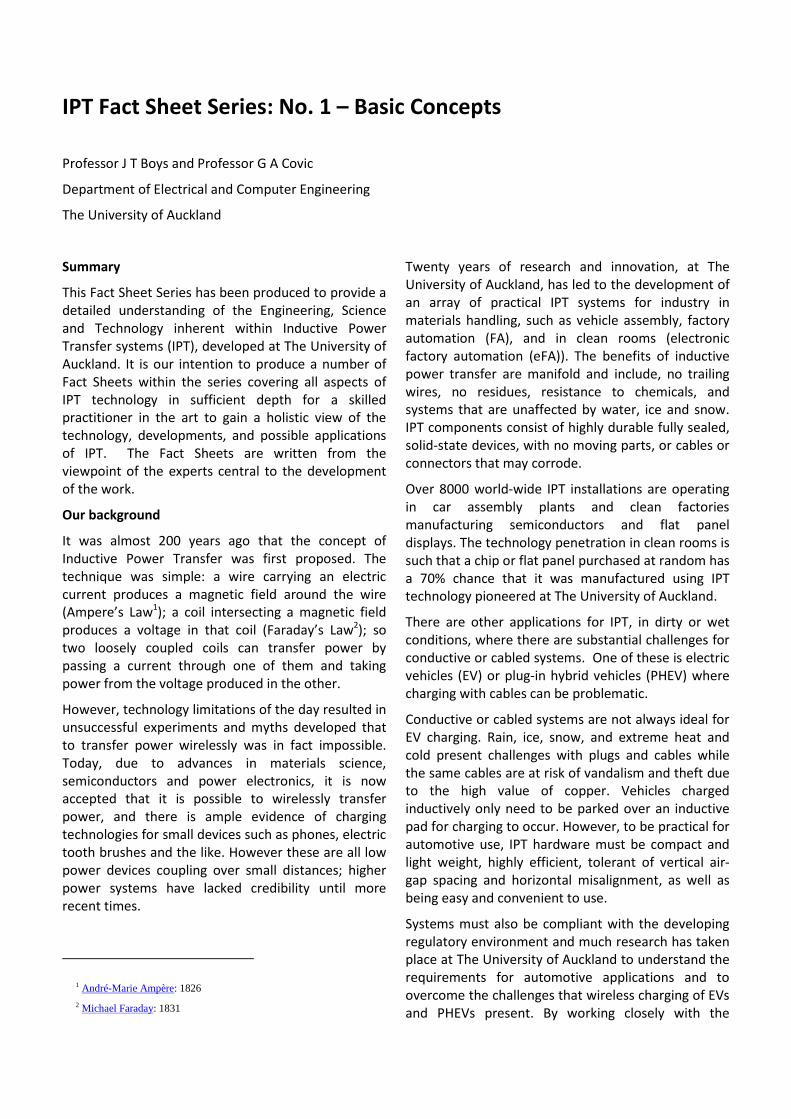
The University of Auckland’s IPT systems have been used in FA and eFA for many years. Implementations commonly employ a track where the primary inductor is an elongated loop of litz wire and a number of carriers (typically in the range 1-100) which maintain a relatively precise alignment with the track while moving independently along it. Power is transferred from the track inductor to various pick-up coils on the carriers. Typical arrangements are shown in Figures 1(a) and 1(b).
(a)
Figure 1a: An IPT eFA track with multiple inductively coupled vehicles moving along a guided trackway
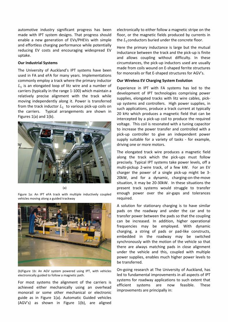
(b)Figure 1b: An AGV system powered using IPT, with vehicles electronically guided to follow a magnetic path.
For most systems the alignment of the carriers is achieved either mechanically using an overhead monorail or some other mechanical or electronic guide as in Figure 1(a). Automatic Guided vehicles (AGV’s) as shown in Figure 1(b), are aligned
electronically to either follow a magnetic stripe on the floor, or the magnetic fields produced by currents in the conductors buried under the concrete floor.
Here the primary inductance is large but the mutual inductance between the track and the pick-up is finite and allows coupling without difficulty. In these circumstances, the pick-up inductors used are usually made from coils wound on E-shaped ferrite structures for monorails or flat E-shaped structures for AGV’s.
Our Wireless EV Charging System Evolution
Experience in IPT with FA systems has led to the development of IPT technologies comprising power supplies, elongated tracks with litz wire cables, pick-up systems and controllers. High power supplies, in such applications, produce a track current at typically 20 kHz which produces a magnetic field that can be intercepted by a pick-up coil to produce the required voltage. This coil is resonated with a tuning capacitor to increase the power transfer and controlled with a pick-up controller to give an independent power supply suitable for a variety of tasks - for example, driving one or more motors.
The elongated track wire produces a magnetic field along the track which the pick-ups must follow precisely. Typical IPT systems take power levels, off a multi-pickup 2-wire track, of a few kW. For an EV charger the power of a single pick-up might be 3-20kW, and for a dynamic, charging-on-the-move situation, it may be 20-30kW. In these situations the present track systems would struggle to transfer enough power over the air-gaps and tolerances required.
A solution for stationary charging is to have similar pads on the roadway and under the car and to transfer power between the pads so that the coupling can be increased. In addition, higher operational frequencies may be employed. With dynamic charging, a string of pads or pad-like constructs, embedded in the roadway may be switched synchronously with the motion of the vehicle so that there are always matching pads in close alignment under the vehicle and this, coupled with multiple power supplies, enables much higher power levels to be transferred.
On-going research at The University of Auckland, has led to fundamental improvements in all aspects of IPT systems for roadway applications to such extent that efficient systems are now feasible. These improvements are principally in:
the power supply design, which permits operation at higher frequencies and power levels than previous systems while maintaining constant frequency under the extreme variability of a dynamic IPT roadway system,
new controllers that display higher stability and efficiency,
new magnetic circuits for coupling on-vehicle pads to ground based pads at higher efficiency over a wider range of misalignment.
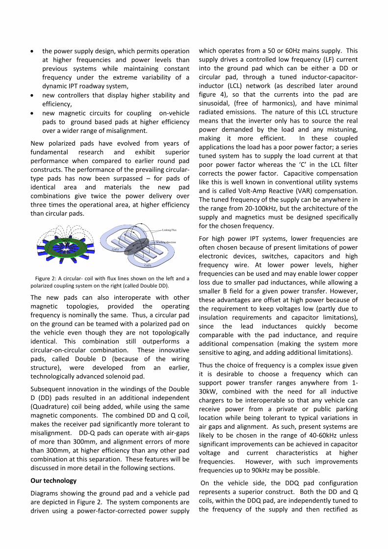
New polarized pads have evolved from years of fundamental research and exhibit superior performance when compared to earlier round pad constructs. The performance of the prevailing circular-type pads has now been surpassed – for pads of identical area and materials the new pad combinations give twice the power delivery over three times the operational area, at higher efficiency than circular pads.
Coil a
Coil b
Winding direction
Linking Flux
Figure 2: A circular- coil with flux lines shown on the left and a polarized coupling system on the right (called Double DD).
The new pads can also interoperate with other magnetic topologies, provided the operating frequency is nominally the same. Thus, a circular pad on the ground can be teamed with a polarized pad on the vehicle even though they are not topologically identical. This combination still outperforms a circular-on-circular combination. These innovative pads, called Double D (because of the wiring structure), were developed from an earlier, technologically advanced solenoid pad.
Subsequent innovation in the windings of the Double D (DD) pads resulted in an additional independent (Quadrature) coil being added, while using the same magnetic components. The combined DD and Q coil, makes the receiver pad significantly more tolerant to misalignment. DD-Q pads can operate with air-gaps of more than 300mm, and alignment errors of more than 300mm, at higher efficiency than any other pad combination at this separation. These features will be discussed in more detail in the following sections.
Our technology
Diagrams showing the ground pad and a vehicle pad are depicted in Figure 2. The system components are driven using a power-factor-corrected power supply
which operates from a 50 or 60Hz mains supply. This supply drives a controlled low frequency (LF) current into the ground pad which can be either a DD or circular pad, through a tuned inductor-capacitor-inductor (LCL) network (as described later around figure 4), so that the currents into the pad are sinusoidal, (free of harmonics), and have minimal radiated emissions. The nature of this LCL structure means that the inverter only has to source the real power demanded by the load and any mistuning, making it more efficient. In these coupled applications the load has a poor power factor; a series tuned system has to supply the load current at that poor power factor whereas the ‘C’ in the LCL filter corrects the power factor. Capacitive compensation like this is well known in conventional utility systems and is called Volt-Amp Reactive (VAR) compensation. The tuned frequency of the supply can be anywhere in the range from 20-100kHz, but the architecture of the supply and magnetics must be designed specifically for the chosen frequency.
For high power IPT systems, lower frequencies are often chosen because of present limitations of power electronic devices, switches, capacitors and high frequency wire. At lower power levels, higher frequencies can be used and may enable lower copper loss due to smaller pad inductances, while allowing a smaller B field for a given power transfer. However, these advantages are offset at high power because of the requirement to keep voltages low (partly due to insulation requirements and capacitor limitations), since the lead inductances quickly become comparable with the pad inductance, and require additional compensation (making the system more sensitive to aging, and adding additional limitations).
Thus the choice of frequency is a complex issue given it is desirable to choose a frequency which can support power transfer ranges anywhere from 1-30kW, combined with the need for all inductive chargers to be interoperable so that any vehicle can receive power from a private or public parking location while being tolerant to typical variations in air gaps and alignment. As such, present systems are likely to be chosen in the range of 40-60kHz unless significant improvements can be achieved in capacitor voltage and current characteristics at higher frequencies. However, with such improvements frequencies up to 90kHz may be possible.
On the vehicle side, the DDQ pad configuration represents a superior construct. Both the DD and Q coils, within the DDQ pad, are independently tuned to the frequency of the supply and then rectified as
current-sources, to the load. Their combined output is then regulated, to provide a controlled voltage and current to the battery, as dictated by the Battery Management System (BMS) on the vehicle. If the power provided by either coil is low it can be shut down without impacting the controllability of the other coil. This ensures maximum efficiency during operation. A communication channel exists between the primary (base unit) and secondary (vehicle unit) control systems, enabling either or a combination of both primary and secondary switching regulation to be used to maximise the efficiency of the entire system.
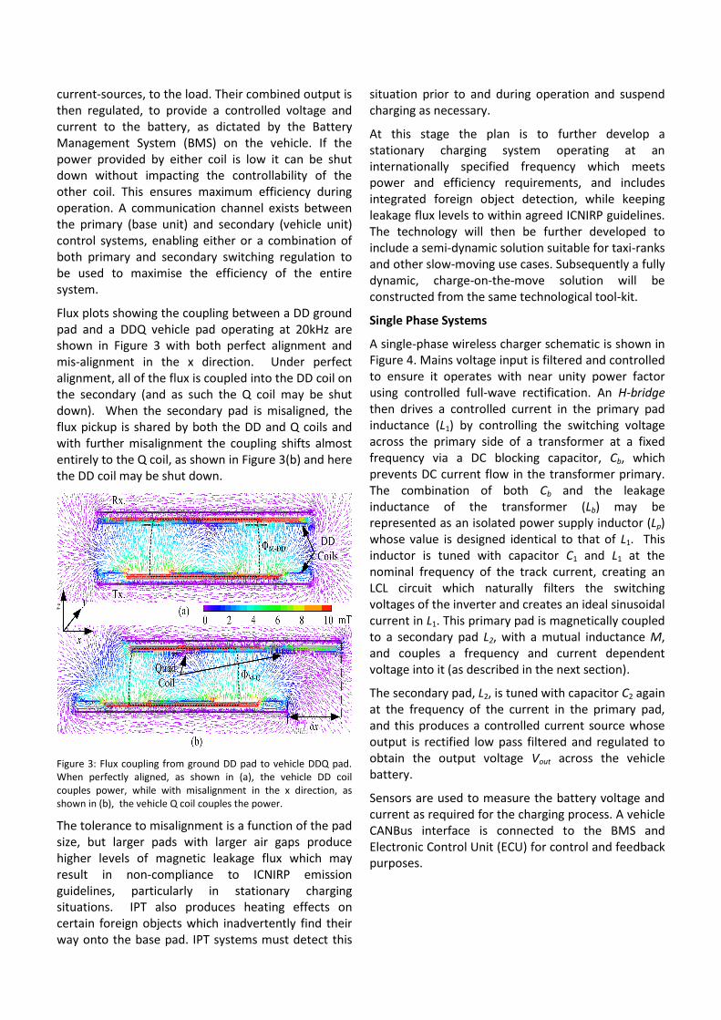
Flux plots showing the coupling between a DD ground pad and a DDQ vehicle pad operating at 20kHz are shown in Figure 3 with both perfect alignment and mis-alignment in the x direction. Under perfect alignment, all of the flux is coupled into the DD coil on the secondary (and as such the Q coil may be shut down). When the secondary pad is misaligned, the flux pickup is shared by both the DD and Q coils and with further misalignment the coupling shifts almost entirely to the Q coil, as shown in Figure 3(b) and here the DD coil may be shut down.
Figure 3: Flux coupling from ground DD pad to vehicle DDQ pad. When perfectly aligned, as shown in (a), the vehicle DD coil couples power, while with misalignment in the x direction, as shown in (b), the vehicle Q coil couples the power.
The tolerance to misalignment is a function of the pad size, but larger pads with larger air gaps produce higher levels of magnetic leakage flux which may result in non-compliance to ICNIRP emission guidelines, particularly in stationary charging situations. IPT also produces heating effects on certain foreign objects which inadvertently find their way onto the base pad. IPT systems must detect this
situation prior to and during operation and suspend charging as necessary.
At this stage the plan is to further develop a stationary charging system operating at an internationally specified frequency which meets power and efficiency requirements, and includes integrated foreign object detection, while keeping leakage flux levels to within agreed ICNIRP guidelines. The technology will then be further developed to include a semi-dynamic solution suitable for taxi-ranks and other slow-moving use cases. Subsequently a fully dynamic, charge-on-the-move solution will be constructed from the same technological tool-kit.
Single Phase Systems
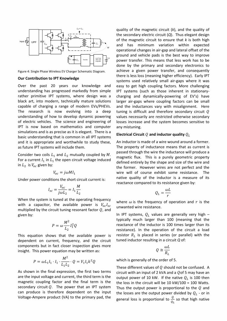
A single-phase wireless charger schematic is shown in Figure 4. Mains voltage input is filtered and controlled to ensure it operates with near unity power factor using controlled full-wave rectification. An H-bridge then drives a controlled current in the primary pad inductance (L1) by controlling the switching voltage across the primary side of a transformer at a fixed frequency via a DC blocking capacitor, Cb, which prevents DC current flow in the transformer primary. The combination of both Cb and the leakage inductance of the transformer (Lb) may be represented as an isolated power supply inductor (Lp) whose value is designed identical to that of L1. This inductor is tuned with capacitor C1 and L1 at the nominal frequency of the track current, creating an LCL circuit which naturally filters the switching voltages of the inverter and creates an ideal sinusoidal current in L1. This primary pad is magnetically coupled to a secondary pad L2, with a mutual inductance M, and couples a frequency and current dependent voltage into it (as described in the next section).
The secondary pad, L2, is tuned with capacitor C2 again at the frequency of the current in the primary pad, and this produces a controlled current source whose output is rectified low pass filtered and regulated to obtain the output voltage Vout across the vehicle battery.
Sensors are used to measure the battery voltage and current as required for the charging process. A vehicle CANBus interface is connected to the BMS and Electronic Control Unit (ECU) for control and feedback purposes.
InputCdc C1
L1
A I p
B
LbCb
LP = L1
UPF
C2L2 Rectifier
Low Pass
Filter and
Regulator
Vout
M
Figure 4: Single Phase Wireless EV Charger Schematic Diagram.
Our Contribution to IPT Knowledge
Over the past 20 years our knowledge and understanding has progressed markedly from simple rather primitive IPT systems, where design was a black art, into modern, technically mature solutions capable of charging a range of modern EVs/PHEVs. The research is now evolving into a deep understanding of how to develop dynamic powering of electric vehicles. The science and engineering of IPT is now based on mathematics and computer simulations and is as precise as it is elegant. There is a basic understanding that is common in all IPT systems and it is appropriate and worthwhile to study these, as future IPT systems will include them.
Consider two coils and mutually coupled by . For a current in the open circuit voltage induced in is given by:
Under power conditions the short circuit current is:
When the system is tuned at the operating frequency with a capacitor, the available power is multiplied by the circuit tuning resonant factor , and given by:
This equation shows that the available power is dependent on current, frequency, and the circuit components but in fact closer inspection gives more insight. This power equation may be written as:
As shown in the final expression, the first two terms are the input voltage and current, the third term is the magnetic coupling factor and the final term is the secondary circuit . The power that an IPT system can produce is therefore dependent on the input Voltage-Ampere product (VA) to the primary pad, the
quality of the magnetic circuit (k), and the quality of the secondary electric circuit (Q). Thus elegant design of the magnetic circuit to ensure that k is both high and has minimum variation within expected operational changes in air-gap and lateral offset of the ground and vehicle pads is the best way to improve power transfer. This means that less work has to be done by the primary and secondary electronics to achieve a given power transfer, and consequently there is less loss (meaning higher efficiency). Early IPT systems used relatively small air-gaps where it was easy to get high coupling factors. More challenging IPT systems (such as those inherent in stationary-charging and dynamically-powering of EV’s) have larger air-gaps where coupling factors can be small and the inductances vary with misalignment. Here tuning is difficult and therefore secondary circuit values necessarily are restricted otherwise secondary losses increase and the system becomes sensitive to any mistuning.
Electrical Circuit and inductor quality
An inductor is made of a wire wound around a former. The property of inductance means that as current is passed through the wire the inductance will produce a magnetic flux. This is a purely geometric property defined entirely by the shape and size of the wire and the former. However wires are not perfect and the wire will of course exhibit some resistance. The native quality of the inductor is a measure of its reactance compared to its resistance given by:
where is the frequency of operation and is the unwanted wire resistance.
In IPT systems, values are generally very high – typically much larger than 100 (meaning that the reactance of the inductor is 100 times larger than its resistance). In the operation of the circuit a load resistor is placed in series (or parallel) with the tuned inductor resulting in a circuit Q of:
which is generally of the order of 5.
These different values of should not be confused. A circuit with an input of 2 kVA and a of 5 may have an output power of 10 kW. If the native is 100 then the loss in the circuit will be 10 kW/100 = 100 Watts. Thus the output power is proportional to the and the losses are the output power divided by - or in
general loss is proportional to
so that high native
values are strongly preferred. In the above power equations the values are assumed to be so high that the loss is neglected.
The Dynamic, Charge-on-the-Move, Challenge
Progressing from the present stationary charging technology to a pragmatic pad-based dynamic coupled system, remains a significant step. Such systems would necessarily require more power than any stationary implementation.
The environment is challenging in the extreme; the efficiency and reliability needed along with managing increased and constantly varying misalignments is daunting. For dynamic applications that are embedded within the road surface, it is likely that air-gaps of more than 250-300 mm are required. Tolerance to misalignment of +/- 300 mm may also be needed to cope with lane drifting during highway motoring. Any dynamic IPT system will need to meet these criteria with overall efficiency of up to 85% or more, at power transfer levels of 10-30 kW or larger. Lower dynamic power transfer efficiency is not restrictive as there is an efficiency gain of more than 15% by powering the motor directly rather than supplying power via a battery with the associated battery losses.
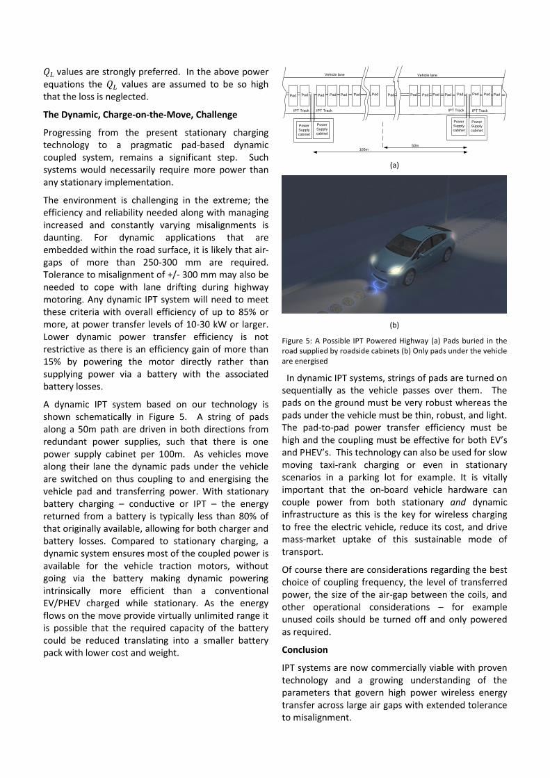
A dynamic IPT system based on our technology is shown schematically in Figure 5. A string of pads along a 50m path are driven in both directions from redundant power supplies, such that there is one power supply cabinet per 100m. As vehicles move along their lane the dynamic pads under the vehicle are switched on thus coupling to and energising the vehicle pad and transferring power. With stationary battery charging – conductive or IPT – the energy returned from a battery is typically less than 80% of that originally available, allowing for both charger and battery losses. Compared to stationary charging, a dynamic system ensures most of the coupled power is available for the vehicle traction motors, without going via the battery making dynamic powering intrinsically more efficient than a conventional EV/PHEV charged while stationary. As the energy flows on the move provide virtually unlimited range it is possible that the required capacity of the battery could be reduced translating into a smaller battery pack with lower cost and weight.
(a)
(b)
Figure 5: A Possible IPT Powered Highway (a) Pads buried in the road supplied by roadside cabinets (b) Only pads under the vehicle are energised
In dynamic IPT systems, strings of pads are turned on sequentially as the vehicle passes over them. The pads on the ground must be very robust whereas the pads under the vehicle must be thin, robust, and light. The pad-to-pad power transfer efficiency must be high and the coupling must be effective for both EV’s and PHEV’s. This technology can also be used for slow moving taxi-rank charging or even in stationary scenarios in a parking lot for example. It is vitally important that the on-board vehicle hardware can couple power from both stationary and dynamic infrastructure as this is the key for wireless charging to free the electric vehicle, reduce its cost, and drive mass-market uptake of this sustainable mode of transport.
Of course there are considerations regarding the best choice of coupling frequency, the level of transferred power, the size of the air-gap between the coils, and other operational considerations – for example unused coils should be turned off and only powered as required.
Conclusion
IPT systems are now commercially viable with proven technology and a growing understanding of the parameters that govern high power wireless energy transfer across large air gaps with extended tolerance to misalignment.
Power
Supply
cabinet
Vehicle lane
IPT Track
Power
Supply
cabinet
Vehicle lane
Power
Supply
cabinet
Power
Supply
cabinet
IPT TrackIPT TrackIPT Track
PadPadPadPad Pad PadPad PadPad PadPad PadPad Pad PadPad
100m50m

New pad innovations and designs coupled with an increased knowledge of magnetics, resonance and the science and mathematics underpinning IPT prove that costwise the technique is comparable to conductive charging. In addition the DDQ pad architecture delivers substantial efficiency benefits while making compliance to industry regulations easier to achieve.
Although 20 years ago the initial IPT research objective was founded on dynamic charging, in the EV market, stationary IPT will be the initial deployment
with dynamic IPT following as systems are tested and rolled out. This work should help the EV industry deliver compliant, interoperable, wireless EV charging hardware and infrastructure supporting new global transportation initiatives and programs.
- End -