Ipsec rbe guide
59
1 IPSec Router Based Encryption Engineering Guide Version 2.4 Document Revision and Review History Version Date Compiled by Description 1.0 01/20/2003 George Lai First Draft 2.0 04/26/2004 Richard Hou Second Draft 2.1 03/10/2005 Corinne Narassiguin Yearly review updates 2.2 10/25/2005 Ali iloglu RSA-sig with generated keys is added. GRE tunneling section is updated to highlight the importance. 2.3 3/8/2006 Ali iloglu ISR throughputs and limitations added. Minor changes made to make it consistent with IPSec Standard. 2.4 5/10/2006 Jeevan Balasubramanian ISR Throughput Numbers Updated, VAM2+ Throughput Numbers Included, Cheat Sheet for ISR routers and authentication methods included in the Appendix 1
-
Upload
wahyu-nasution -
Category
Technology
-
view
116 -
download
2
Transcript of Ipsec rbe guide

1
IPSec Router Based EncryptionEngineering Guide
Version 2.4
Document Revision and Review History
Version Date Compiled by Description1.0 01/20/2003 George Lai First Draft
2.0 04/26/2004 Richard Hou Second Draft2.1 03/10/2005 Corinne Narassiguin Yearly review updates
2.2 10/25/2005 Ali iloglu
RSA-sig with generated keys is added. GRE tunneling section is updated to highlight the importance.
2.3 3/8/2006 Ali iloglu
ISR throughputs and limitations added. Minor changes made to make it consistent with IPSec Standard.
2.4 5/10/2006 Jeevan Balasubramanian
ISR Throughput Numbers Updated, VAM2+ Throughput Numbers Included, Cheat Sheet for ISR routers and authentication methods included in the Appendix
1

2
Table of Content
1 Introduction..............................................................................................................................................32 IPSec Overview........................................................................................................................................4
2.1 IKE (ISAKMP/Oakley) Protocol.....................................................................................................42.1.1 Phase 1......................................................................................................................................42.1.2 Phase 2......................................................................................................................................5
2.2 Authentication Header (AH) Protocol..............................................................................................52.2.1 AH in Transport Mode.............................................................................................................62.2.2 AH in Tunnel Mode..................................................................................................................6
2.3 Encapsulating Security Payload (ESP) Protocol..............................................................................62.3.1 ESP in Transport Mode............................................................................................................72.3.2 ESP in Tunnel Mode................................................................................................................7
3 Network Design Considerations...............................................................................................................73.1 Applications......................................................................................................................................73.2 Platforms...........................................................................................................................................83.3 High Availability and Resiliency.....................................................................................................9
3.3.1 IKE Keepalive........................................................................................................................103.3.2 Independent IPSec Tunnels....................................................................................................103.3.3 Loopback Address Considerations.........................................................................................11
3.4 Routing...........................................................................................................................................123.5 HSRP..............................................................................................................................................123.6 GRE Tunneling...............................................................................................................................13
4 Other Considerations..............................................................................................................................174.1 IPSec Modes...................................................................................................................................174.2 NAT................................................................................................................................................174.3 Firewall...........................................................................................................................................174.4 Fragmentation and MTU................................................................................................................184.5 Compression...................................................................................................................................214.6 Rate-Limiting IPSec Traffic...........................................................................................................21
5 Configuration Tasks...............................................................................................................................225.1 Create ISAKMP Policies................................................................................................................225.2 Configure Authentication with RSA Keys.....................................................................................23
5.2.1 Generate RSA Public/Private Key Pair..................................................................................235.2.2 RSA Encrypted Nonce Authentication...................................................................................255.2.3 RSA-Sig Authentication with Generated Keys......................................................................275.2.4 RSA Digital Signature Authentication...................................................................................28
5.3 Configure IPSec Transforms..........................................................................................................325.4 Specify Access Lists.......................................................................................................................335.5 Create Crypto Maps........................................................................................................................345.6 Apply Crypto Maps........................................................................................................................35
6 References..............................................................................................................................................377 Appendices.............................................................................................................................................38
7.1 Appendix A – Fragments in IPSec RBE Network.........................................................................387.2 Appendix B – IPSec Authentication Methods + ISR Routers........................................................42
2

3
1 Introduction
Internet Protocol Security (IPSec) is a framework of open standard for transferring information securely over IP networks. Based on IETF standards, IPSec provides a robust, flexible means to ensure confidentiality, integrity and authenticity for data communication across public networks. With the support of Internet Key Exchange protocol (IKE, formally known as ISAKMP/Oakley) and the interoperability of Certificate Authority (CA), IPSec further becomes a highly scalable solution for large-scale deployment.
This document is designed to provide design and engineering guidelines for deploying IPSec RBE networks in Citigroup. The scope of the document is limited to Cisco routers only. IPSec overview is given in Section 2 to familiarize the readers with the IPSec protocols and terminology. Section 3 and 4 cover the design considerations and known issues at a higher level. Configuration tasks are described in Section 5 to demonstrate how IPSec RBE is configured on Cisco routers. New IPSec features will be included in the future revision of this document if they prove to be useful.
3

4
2 IPSec Overview
IPSec is an open standard defined by IETF for IP network layer security. It is a suite of protocols that includes AH (Authentication Header), ESP (Encapsulating Security Payload) and IKE (Internet Key Exchange) protocols. Collectively they provide the services for data integrity, authentication, confidentiality and replay protection in secure communications across IP networks. With the support of Internet Key Exchange protocol and the interoperability of Certificate Authority (CA), IPSec further becomes a highly scalable solution for large-scale deployment.
2.1 IKE (ISAKMP/Oakley) Protocol
Internet Key Exchange (IKE) protocol, also referred to as ISAKMP/Oakley, is a framework that provides the functionality of automated negotiation of IPSec Security Associations (SAs) and the management of cryptography key generation and refreshing. Protecting keying material is the most crucial component in secure communications since no matter how strong the cryptography algorithm is; there will be no security if the keying material is compromised.
IKE is designed to provide the protection against security exposures such as denial of services and man in the middle attacks. Optionally, it provides the property of perfect forward secrecy (PFS) so that compromise of past key material provides no useful clues for breaking current or future keys.
IKE adopted a two-phase approach to ensure the robustness of the key exchange procedure. It uses UDP port 500 for communication.
The term ISAKMP will be used interchangeably with IKE throughout this document.
2.1.1 Phase 1
Phase 1, also referred to as Oakley Main Mode (MM), is all about protecting the ISAKMP messages themselves. During the negotiations, it uses public key cryptography to establish a protecting suite known as ISAKMP Security Association (SA). Upon successful completion, the peers will be mutually authenticated and a master secret is established. The following authentication methods are defined for IKE:
Pre-shared Key Digital Signature (Digital Certificate) Public Key Encryption (Encrypted Nonce)
The master secret will be used to further derive keys that protect the ISAKMP messages in subsequent Phase 2 negotiations; during which the very master secret is used to derive cryptography keys for protecting user’s data traffic. The cryptography operations performed in Phase 1 negotiations are more processor intensive than those in Phase2 but only need to be executed less frequently. Indeed, multiple Phase 2 exchanges can be executed during the lifetime
4

5
of an ISAKMP SA established by a single Phase 1 exchange. In Phase 1, the peers agree on an encryption algorithm, a hash algorithm and a Diffie-Hellman group identifier used for protecting IKE messages. The peers also propose lifetime for ISAKMP SA during negotiations and agree on the shorter one. Note that ISAKMP SA is bidirectional, a single SA protects the ISAKMP messages flowing in both directions.
2.1.2 Phase 2
Phase 2, also referred to as Oakley Quick Mode (QM), is a set of negotiations to establish non-ISAKMP Security Associations (SAs) and cryptography keys to protect user’s data traffic. Non-ISAKMP SA will also be referred to as IPSec SA throughout this document. Phase 2 is all about setting up the protecting suite for user’s data traffic. In Phase 2, the negotiating peers agree upon the IPSec transforms they propose by selecting the first matched one, if multiple transform sets are offered. An IPSec transform is the specific implementation of an algorithm for use by an IPSec protocol. For example, the triple DES algorithm used in ESP is called ESP-3DES transform and the HMAC variant of SHA hash algorithm used in AH is called AH-SHA-HMAC.
Note that IPSec SA is a unidirectional logical connection uniquely identified by:
<Security Parameter Index, IP Destination Address, Security Protocol>
Security Parameter Index (SPI) is used to differentiate multiple SAs with the same IP destinations and security protocols. An IPSec SA is required for each traffic direction and for each security protocol (ESP or AH). For example, if both AH and ESP are used to protect the data, a total of 4 IPSec SAs are required to establish a 2-way communication; 2 for AH, inbound and outbound and the other 2 for ESP, inbound and outbound. It is logical to regard these 4 closely related IPSec SAs, along with their protecting ISAKMP SA, as an “IPSec tunnel” which can be viewed as an bidirectional, secure data flow.
It is important that the readers draw distinctions between the IPSec SA discussed in this section and the ISAKMP SA discussed in the previous section.
2.2 Authentication Header (AH) Protocol
Authentication Header (AH) protocol is designed to provide integrity check and authentication to IP packets. These services are combined and carried out via the authentication data (hash value) in AH header. A monotonically increasing sequence number is used to provide anti-replay protection. As a result, out of order AH packets will be rejected outside a sliding receive window. AH processing is performed on a per-packet basis and it authenticates the whole IP packet except the mutable fields in the outermost IP headers. Mutable fields in IPv4 header includes
Type of Service (TOS) Flags Time to Live (TTL) Header Checksum
5

6
AH can be operated in either transport mode or tunnel mode.
2.2.1 AH in Transport Mode
As shown in Figure 1, in transport mode AH header is inserted into the original packet, right after the IP header. The mutable fields in the original IP header are not authenticated. Transport mode is typically used by host to host IPSec tunnels.
2.2.2 AH in Tunnel Mode
In tunnel mode, the original IP packet is encapsulated as the payload of a new IP packet. AH transport mode is then applied to the new packet. The mutable fields in the new IP header are not authenticated but the original IP packet, including its mutable fields, are authenticated. This is considered an advantage since it provides total protection to the original packet and it creates the possibility of using private addresses. The disadvantage of using tunnel mode is the additional 20-byte overhead introduced by the new IP header.
Figure 1 - Authentication Header (AH) Protocol
AH is identified by IP protocol number 51, assigned by IANA.
2.3 Encapsulating Security Payload (ESP) Protocol
Encapsulating Security Payload (ESP) protocol is designed to provide integrity check, authentication and encryption to IP packets. Integrity check and authentication services are combined and carried out via the authentication data in ESP Authentication Data field. A monotonically increasing sequence number is used to provide anti-replay protection. As a result, out of order ESP packets will be rejected outside a sliding receive window. ESP processing is performed on per-packet basis.
Although both authentication (with integrity check) and encryption are optional, at least one of them has to be selected. ESP processing includes the addition of an ESP header, an ESP trailer
6

7
and ESP authentication data to the original IP packet. ESP trailer contains padding since most encryption algorithms require that input data be an integer number of blocks. DES, and thus triple DES, cipher uses 64-bit blocks, for instance.
ESP can be operated in either transport mode or tunnel mode.
2.3.1 ESP in Transport ModeAs shown in Figure 2, in transport mode an ESP header is inserted into the original packet, right after the IP header. The ESP trailer and ESP authentication data are then appended to the payload. ESP encrypts the IP payload and ESP trailer. If authentication service is selected, ESP authenticates ESP header, IP payload and ESP trailer. Note that the IP header is not protected by authentication as in AH protocol.
2.3.2 ESP in Tunnel ModeIn tunnel mode, the original IP packet is entirely encapsulated in a new IP packet. ESP transport mode is then applied to the new packet as illustrated in Figure 2. Note that the original IP packet becomes the payload of the new packet and can be fully protected by encryption and authentication. The disadvantage of using tunnel mode is the additional 20-byte or so overhead introduced by new IP header and necessary padding.
Figure 2 - Encapsulating Security Payload (ESP) Protocol
ESP is identified by IP protocol number 50, assigned by IANA.
3 Network Design Considerations
3.1 Applications
The potential areas of deployment for IPSec RBE in Citigroup are:
7

8
Hub and Spoke Branch Networks Replacement for Layer-2 Link Encryptors Site to Site VPNs (B2B)
3.2 Platforms
IPSec processing is supported in Cisco IOS software. However, IPSec processing is highly CPU intensive and therefore it is inefficient and impractical to perform software-only IPSec processing. Cisco offers hardware IPSec accelerators, which offload the IPSec processing from the router processors, on various platforms. Deployment of software-only IPSec RBE networks should be avoided.
Bandwidth throughput and the maximum number of IPSec tunnels supported on Cisco platforms are the typical measurements in evaluating IPSec performance. In general, the maximum number of IPSec tunnels supported by the platforms is adequately sufficient in IPSec RBE scenarios. The bandwidth throughput, on the other hand, is the key consideration for platform selection. The following table contains a list of the Cisco platforms and the IPSec hardware accelerators (VPN modules) they support. Throughput numbers, which are measured at approximately 50% CPU utilization for 7206VXR and at 60-65% for others, are reported by Cisco Enterprise Solutions Engineering VPN Team.
Router HW VPN Module Throughput # of Tunnels Deployed As6509 VPN SM 850 Mbps 8000 Hub router7206VXR ISA-VPN 30.0 Mbps 5000 Hub router7206VXR VAM 45.0 Mbps 5000 Hub router7206VXR VAM2+ 60.0 Mbps Not Tested Hub Router38451 Embedded VPN
Module25.0 Mbps Not Tested Branch or Hub Router
3845 VPN/HPII-PLUS 30.0 Mbps Not Tested Branch or Hub Router
3745 AIM-VPN/HP 16.0 Mbps 1800 Hub or Branch router3662 AIM-VPN/HP 16.0 Mbps 1800 Hub or Branch router3640 NM-VPN/MP 3.5 Mbps 800 Branch router3620 NM-VPN/MP 1.8 Mbps 800 Branch router28112 Embeded VPN
Module 6.5Mbps Not Tested Branch router
2651XM AIM-VPN/EP > 2.8 Mbps 800 Branch router2651 AIM-VPN/EP > 2.8 Mbps 800 Branch router2621 AIM-VPN/BP 2.4 Mbps 300 Branch router
2611 AIM-VPN/BP 2.0 Mbps 300 Branch router1841* Embedded VPN
Module6.0 Mbps Not Tested Branch router, Kiosk
1760 AIM-VPN TBA 100 Branch router, Kiosk
1751 AIM-VPN 2.6 Mbps 100 Branch router, Kiosk
1 Embedded VPN module does not support AH+ESP transform set, so AIM HPII plus is recommended, which does not support rsa-encr. Number of actual GRE tunnel is not tested but that is not scale limiting factor in our applications.2 Throughput is measured with 99% CPU on 2811 and 1841 by Cisco. Some room should be left in actual deployment.
8

9
Cisco IPSec RBE can be deployed on almost any physical and logical interfaces capable of carrying IP traffic. High-speed WAN links will use VPN-SM and VPN-SPA ( next generation encryption card under test replacing VPN-SM) in 6500. The following interfaces are either already deployed in Citigroup network or known to work with IPSec RBE:
T1/E1, T3/E3 interfaces and Inverse MUX of them Asynchronous serial interfaces HSSI interfaces V.35 interfaces ATM point-to-point sub-interfaces Frame Relay point-to-point sub-interfaces Ethernet and Fast Ethernet interfaces 802.1Q and ISL sub-interfaces ISDN interfaces GRE tunnel interfaces
IPSec RBE also works with DLSW+ traffic.
There are certain IPSEC cards, which does not support rsa-encr. AIM-BP2 AIM-EP2 AIM-HP2
Also, currently there is bug (CSCsc65207) on ISR release, which limits the use of 1024 size key length, which will be fixed 12.4(3d) and 12.3.(11)T10 codes for ISR.
3.3 High Availability and Resiliency
High availability and resiliency after fail-over is critically important for Citigroup network design. IPSec RBE network should be designed to work in sync with the resilient design of the underlying network. It should not introduce new limiting factors that would degrade the inherited resiliency. The major concern on potential resiliency degradation regards the persistency of SAs which may prevent the underlying fail-over mechanism from functioning. This sticky property results from the fact that IPSec protocol provides no mechanism to detect the lost of connectivity.
SAs are stateful relationships between the two peers. The state information includes, but is not limited to, secret keys, security parameters, and peer identity. This state information is established during the MM negotiation for ISAKMP SAs and during QM negotiation for IPSec SAs. ISAKMP SAs, once established, will live through its lifespan as specified in ISAKMP configuration. There are only two conditions under which an ISAKMP SA be removed automatically. The first condition is when the lifetime associated with the SA is reached. This is considered the natural aging of the SA. If there is interesting traffic on the wire, within a small grace period of time before the SA expires, a new SA will be negotiated so that the data traffic will not be interrupted when the old SA expires. The second condition is when the local peer eventually realizes the lost of connectivity in failing to renew IPSec SAs in QM negotiation at the
9

10
expiration of the old IPSec SAs. This implies that a black hole situation may exist for as long as 1 hour, the IPSec SA lifetime mandated by GNAST IPSec RBE standard [1].
3.3.1 IKE Keepalive
IKE keepalive is a Cisco proprietary means against black hole situation described above. If enabled, if the local peer misses 3 keepalive messages, it concludes that the connectivity is lost and it proceeds to purge the IKE SA and the IPSec SAs associated with it. However, IKE keepalive alone cannot satisfy all the requirements in a resilient network design. Consider the following scenario that router X establishes dual peering relationships with router A (primary) and router B (backup) by specifying both peers in a single crypto map.
A subtle point is that at any given time, there exists only one ISAKMP SA in this scenario. Under normal circumstances, the primary tunnel (indicated by solid line) is active. The backup tunnel, (indicated by dashed line) does not even exist, i.e., none of the SAs associated with the backup tunnel exist, until the SAs associated with the primary tunnel are purged. When the fail-over takes place, it requires fresh MM and QM negotiations to establish the backup tunnel. Then the roles of the primary and backup tunnels simply reverse. IKE keepalive can contribute to better fail-over behavior if the keepalive timers are carefully calibrated to account for the convergence time of the underlying routing protocol plus the time for tunnel establishment.
However, as reported by Cisco [2], there are still open issues with IKE keepalive mechanism:
IKE keepalive is not always available IPSec performance degradation has been witnessed with IKE keepalive The remote site does not switch back to its original peer once the peer is restored
So, the recommendation is to tie routing with IPSec by using GRE tunneling as discussed in detail at RBE standard.
3.3.2 Independent IPSec Tunnels
10

11
It is evident at this point that more robust resiliency can be achieved by having two independent IPSec tunnels associated with the primary and backup sites, instead of only one tunnel switching back and forth. This involves creating multiple logical interfaces on router X so that each logical interface can be applied a separate crypto map which results in independent IPSec tunnels as illustrated by the diagram below.
GRE tunneling is the most common approach for this purpose. However, GRE tunnel introduces 15-20% performance degradation in addition to IPSec processing overhead to the network. Other GRE issues will be discussed in later section. However, GRE tunneling allows IPSec to tie with routing protocols like OSPF. So, when IPSec fails, routing protocol fails. So, routing protocol keep lives detect IPSec level failures to move traffic to backup tunnel.
3.3.3 Loopback Address Considerations
IPSec RBE is essentially a point-to-point operation. Inherited from the fact that current IPSec standard does not support multicast or broadcast traffic, the point-to-point relationship is built upon the peers’ unicast IP addresses. The binding of the peers is further fortified by the need to apply crypto maps, as indicated by the ellipses in the following diagram, on the interfaces that IPSec tunnel traverses.
11

12
The use of loopback as IPSec peer’s address indeed breaks the tight binding of the specific interfaces to IPSec tunnel. In the example, if the serial interfaces are used as the peer’s addresses between router A and X, an IPSec tunnel will be established as designed (gray line). Crypto maps (gray ellipses) need to be applied on the serial interfaces on both router A and X. In this case, the tunnel is in sync with the underlying serial link.
On the other hand, if loopback is used as the peer’s address, it creates an alternative path (indicated by red line) for the IPSec tunnel, i.e., the path traversing A-B-Y-X. However, for that alternative path to form a functional IPSec tunnel, crypto maps need to be applied on all possible interfaces the alternative path traverses. In this case, additional crypto maps (red ellipses) are required to be applied on the fa0/0 interfaces on both router A and X. This is an undesirable side effect and it complicates the design. It also violates the next hop only rule for building IPSec tunnels as described in GNAST IPSec RBE standard [1].
It is interesting to contrast IPSec tunnel with GRE tunnel. It may be desirable in some cases that GRE tunnel is built upon loopback addresses. The advantage of doing so is that there may exist alternative underlying paths that the GRE tunnel can actually traverse. This makes the GRE tunnel more resistant to link failure occurred in the underlying network. The alternative paths may be suboptimal though. Unfortunately, the analogy is not applicable to its IPSec tunnel counterpart.
As a matter of fact, in IPSec RBE design, it is preferred that an IPSec tunnel is only associated with an underlying path. Upon failure, the traffic quickly switches to the pre-provisioned backup tunnel. This simple approach generally results in less complicated configuration and highly predictable behavior which make the network more manageable.
3.4 Routing
IPSec RBE does not impose additional requirements on the routing of underlying network. IGP (e.g. OSPF, EIGRP) routing traffic should be pushed inside the IPSec tunnel as best design practice. This will not only provide security to routing protocol but also tie IPSec failures with IPSec.
3.5 HSRP
HSRP provides the resiliency on the LAN side. In an IPSec RBE network scenario as shown below, the worst impact of HSRP is the possibility of an extra hop. Highlights of the RBE configurations are:
First hop approach is used for IPSec peering Primary and backup IPSec tunnels are independently established Dynamic routing is configured on both WAN and LAN sides IKE keepalive is configured HSRP preemptive is enabled and priority is set higher on X HSRP tracks the WAN link
12

13
It is logical to configure router X, which is associated with the primary IPSec tunnel, as the HSRP active router. When the link between X and A is down or when router A crashes, the route that traverses the primary IPSec tunnel will be removed from X’s routing table. However, the data traffic coming out from the LAN side will still be using the active router, X, as the first hop. Since the LAN segment participates in the routing, the traffic will be sent back to the LAN in clear from X to Y and then traverses the backup IPSec tunnel. The returned traffic will take the backup tunnel since router A no longer advertises the route to the LAN via the primary tunnel. The inefficiency of the extra hop may be eliminated by tracking the WAN link on X in its HSRP configuration. However, HSRP tracking may not always yield the desire result. For example, an Ethernet WAN connection plugging into the carrier’s switch will be always up even if the remote peer’s interface is down.
A potential problem exists if the network outage is quickly resolved and the connectivity between router X and A is restored. If it was a link problem, the SAs associated with the primary IPSec tunnel are still available on both A and X. Therefore the primary IPSec tunnel is restored in no time. However, if the outage resulted in router A to reload, a black hole scenario will surface and lasts until the next QM negotiation. With IKE keepalive enabled, the network is immune to this black hole scenario.
3.6 GRE Tunneling
The need to use GRE tunneling in IPSec RBE network falls into three categories:
1. Multi-protocol support is needed to encapsulate legacy protocols in IP 2. Multiple logical paths are needed for resilient design3. Complicated ACLs for encrypted traffic become infeasible or impractical4. Encrypting IPSec Multicast traffic 5. The most importantly, GRE tunneling ties IPSec failures with routing protocol failures to
avoid traffic black holing.3
3 Multicast based routing like OSPF protocol requires GRE tunneling. Also, BGP can require GRE tunneling over IP based transport networks. In future, we plan to use virtual IPSec interfaces to avoid GRE tunneling overhead.
13

14
It is strongly recommended to use GRE tunneling to avoid routing protocol stay up and send traffic over IPSec failed links.
The issues incurred by using GRE tunnel are discussed below.
Performance Degradation
GRE encapsulation, as illustrated in the above diagram, can introduce 5-25% performance degradation, depending on the packet sizes. The performance degradation is observed even when CEF or fast switching is in effect. It results from the encapsulation header which adds additional 24 bytes to the original packets. Additional sources of the performance degradation may come from
1. Encapsulation processing that falls back to process switching in earlier IOS versions2. The need for pre-fragmentation at GRE ingress routers3. The need to reassemble GRE fragments at GRE tunnel egress routers4. The need to reassemble IPSec fragments at IPSec tunnel egress routers
The following table demonstrates the performance degradation by throughput numbers (Mbps) measured in a Lab environment using Ixia traffic generator. The device under test is a 7206VXR running IOS 12.2(7a) with NPE400 processor board and VPN ISA card. IMIX traffic is a repeated sequence of frames with size pattern 64-64-570-64-64-570-64-1400-570-64-64-570. CEF switching is turned on. Note that the router CPU utilization is close to 100% when these numbers were measured. The test data are Ethernet frames. The size of Ethernet frame is the IP packet size plus 18 bytes (14-byte Ethernet header and 4-byte Ethernet FCS).
Frame Size 64 256 1400 IMIXTheoretical Limit 76.19 92.75 98.59 94.50Baseline 76.19 92.75 98.59 94.49GRE 59.30 85.33 96.99 88.453DES 17.30 53.11 70.73 56.703DES + GRE 14.50 46.38 69.36 56.67
The following table contrasts the performance degradation with and without GRE reassembling. Fragments are CEF switched (first column) yet reassembling can only be process switched (second column).
Frame Size 1496 (w/o GRE reassem.) 1496 (w/ GRE reassem.)
14

15
GRE 92.26 20.86
When IPSec processing is involved, reassembling is inevitable for frames larger than 1494 bytes. The fragmentation and reassembling take place at different levels though. The following table contrasts the performance degradation with and without GRE reassembling, respectively, when CEF switching is on.
Frame Size 1496 (w/o GRE reassem.) 1496 (w/ GRE reassem.)3DES + GRE ~15.00 8.46
The following table illustrates the throughput results as that in the above table except fast switching is used instead of CEF switching.
Frame Size 1496 (w/o GRE reassem.) 1496 (w/ GRE reassem.)3DES + GRE 12.42 14.60
The impact of GRE overhead should be taken into account when IPSec is implemented
Fragmentation and Reassembling
The impact of fragmentation incurred by GRE and IPSec header/trailer overhead can be more far-reaching than merely performance degradation when firewalls or similar devices are involved. In the worst scenario, the end users will experience unpredictable connectivity problems over IPSec RBE network that some applications work fine and others fail. The discussion of these problems (which are MTU related), their causes and possible solutions will be deferred until later section.
Whether by design or not, once fragmentation occurs on one end, reassembling may take place at the other end. Reassembling is a resource intensive process. Not only it cannot be fast or CEF switched but it also requires the use of huge buffers (18,024 bytes in size) on the routers. This is because IP fragments do not carry any information about the original IP packet size. Routers have no way to know how much buffer space is needed for reassembling until the last fragment is received. Therefore, routers have no choice but to request a huge buffer upon receiving the first fragment. Furthermore, since the default permanent number of huge buffers is zero, each huge buffer hit also results in a huge buffer miss; if there’s none already exists. Hence it may be necessary to perform buffer tuning if fragments cannot be totally eliminated in the networks.
Interested readers should turn to Appendix A for how GRE tunneling incurs fragmentation.
Cisco Crypto map Caveat
A long-lived Cisco bug regarding how crypto map is applied on GRE tunnel interface is worth mentioning. This bug case (CSCdk59089, CSCdw03713) describes the misbehavior of the need to apply crypto map on both physical and GRE tunnel interfaces. The fix was later backed out since it caused 7200 and RSP platforms to reload as described in bug case CSCuk27481. Under the influence of this bug (most IOS versions are), a crypto map set is required to bypass the problem when multiple GRE tunnels are configured on a single physical interface. Such crypto
15

16
map set will contain multiple crypto map entries. All of the crypto map entries in the crypto map set share the same map name yet with different map sequence numbers. Each of the crypto map entry is associated with a single GRE tunnel. The router will evaluate the traffic passing through the interface against the applied crypto map set. Inefficiency is introduced that each crypto map entry is evaluated in sequence until the traffic is matched.
Since the bug status is in flux, it is advisable that the workaround be used so that functionality is guaranteed regardless of the IOS versions. The correct configuration (applying independent crypto map on each GRE tunnel) can be attempted, if desired, for IOS versions newer than 12.1(12)E, 12.2(10), and 12.2(8)T.
16

17
4 Other Considerations
4.1 IPSec Modes
IPSec protocols (ESP and AH) can operate in either tunnel mode or transport mode. Tunnel mode is required for use with security gateways, in which case IPSec peers are security proxies for the protected end hosts. Transport mode is used for end to end security in which case IPSec peers themselves are the end hosts. GRE tunneling creates a unique scenario that transport mode is applicable. In theory, the use of transport mode increases bandwidth efficiency. However, Lab tests showed statistically indifferent throughput numbers between these two modes when hardware IPSec modules are in use. Cisco engineers speculated that the hardware modules are optimized for tunnel mode. It is design engineers’ judgment to determine if transport mode is critically necessary from bandwidth efficiency perspective.
4.2 NAT
Network Address Translation (NAT) is typically used at the firewalls for various purposes. AH protocol, by its nature, will not work if the IPSec tunnel traverses a NAT device. This is because AH authenticates the IP header, including the outermost one. When a NAT device translates the addresses for an AH packet, the resulting packet will not pass the authentication check on the other end of the tunnel and the NATed packet will be dropped. If an IPSec tunnel has to traverses a NAT device, using ESP in tunnel mode is the only way.
4.3 Firewall
If an IPSec tunnel passes through a firewall, the existing filtering needs to be modified to permit protocol 50 for ESP, protocol 51 for AH and UDP port 500 for ISAKMP negotiations. Since the content of packets protected by ESP encryption cannot be examine by the firewalls, it is not uncommon to deploy a dual-firewall topology that IPSec filtering is performed at the outer firewall and the usual data packet filtering takes place at the inner firewall.
A common issue associated with firewall, even if IPSec RBE is not involved, is the permission for ICMP type 3 code 4 packets to pass the firewall. ICMP type 3 code 4 packets signal a situation that fragmentation needed but Don't Fragment (DF) bit was set in the committed packet’s IP header. The use of ICMP type 3 code 4 packets is a crucial component for path MTU Discovery (pMTU-D) protocol to work. Connectivity problems may occur if ICMP type 3 code 4 packets are blocked at the firewall for scenarios which meet the following conditions:
1. The link with the smallest MTU size is in the middle of an end to end path, rather than the links directly connected to the end hosts
2. Path MTU discovery support is enabled on the end hosts.
In the example illustrated below, a GRE tunnel is configured outside of the firewall. Assume the MTU sizes of the physical links in the end to end path are all 1500 bytes. To account for its
17

18
overhead, routers (A and B) will set the MTU size of the GRE tunnel interfaces to be 24 bytes less than its physical interface, i.e., 1476 bytes. Since pMTU-D support is enabled on the end hosts, all TCP packets will be sent with DF bit set in the IP header. There will be no problems until some applications (e.g. ftp) start to send large packets. When a TCP packet coming out from GDN, traversing the firewall and arriving at router B, it will be dropped by router B if its size is larger than the next hop MTU size, 1476 bytes. While dropping the packet, router B also sends back an ICMP type 3 code 4 packet to the source of the packet, i.e., the end host. This ICMP packet, unfortunately, is blocked by the firewall. As a result, the applications do not know that packets have been dropped because they are too large and the router cannot notify the source host about about the packets being dropped. This is a black hole situation, the TCP applications eventually time out.
Citigroup’s corporate security policies do not permit ICMP type 3 code 4 packets to pass through the firewalls. If it is critically important for the pMTU-D to work across the firewalls, CISO or BISO should be contacted for risk analysis and approval for deviation. ICMP type 3 code 4 packets should not be filtered inside corporate firewalls.
There is also a known issue specific to the CyberGuard firewalls that out of order IP fragments will be dropped immediately. Furthermore, this behavior is not controlled by explicit firewall rules so nothing in the configuration can change the behavior. In the case of TCP traffic and the fragment drop rate is not high, TCP retransmission mechanism will prevent the session from failing. However, there have been incidents reported from production IPSec RBE networks that solely relying on TCP retransmission does not guarantee the networks being immune from this problem. Other firewalls buffer the out of order fragments for a certain period of time before dropping them, therefore alleviate this problem greatly.
Evidently these firewall related issues are not specific to IPSec RBE networks only. However, the encapsulation from both GRE tunneling and IPSec protocols makes the exposure to these problems more likely.
4.4 Fragmentation and MTU
Fragmentation does exist in IP networks for various reasons. It consumes network resources and slows the packet flow down. In some cases, it even results in connectivity problems. Therefore it is highly desirable to avoid fragmentation from happening at all. Path MTU discovery protocol is designed to address this problem from its root. Path MTU discovery is already supported in most modern operating systems for end hosts and routers.
Unfortunately, pMTU-D is not a silver bullet for all fragmentation issues. As a matter of fact, if failing to work end to end, pMTU-D itself can become the problem. The remedy, then, will be to
18

19
disable pMTU-D support. This can be done either on the end hosts, if it’s feasible, or it can be done on the routers by using policy routing to strip the DF bit.
In cases when pMTU-D is not supported by the operating systems of the end hosts or when the application is not TCP based, solutions do not necessarily exist. With CyberGuard firewall related problems, forcing GRE egress to perform reassembling turns out to be a viable solution.
The following table summaries some known issues and potential solutions related to fragmentation and MTU settings:
GRE tunnel outsidefirewall
ICMP 3/4 allowed
TCP trafficHost OS pMTU-Dsupport
Issues & Solutions
Y N Y Y
Issue: End-to-end pMTU-D is not possible, fragments may occur. CyberGuard will drop out of sequence fragments.
Solution:1. Permit ICMP 3 /4 to pass the firewall on a
limited basis.2. Set GRE MTU size to link MTU (1500
typically) to force reassembling. Be aware of reassembling cost.
3. Manually adjust link MTU to the smallest path MTU on end hosts. Not recommended since side effect exists.
Y Y/N Y N
Issue:TCP application determines MSS based on MTU size of directly connected link. Without host OS pMTU-D support, DF bit will not be set therefore ICMP 3/4 will not be sent back. The GRE ingress will perform fragmentation. Out of sequence fragments may be dropped by CyberGuard. If the packets loss rate is high, even TCP retransmission cannot recover the loss, the connection eventually times out.
Solution:Manually adjust link MTU to the smallest path MTU on end hosts. Be aware of the side effect.
Y Y/N N Y Issue:Non-TCP protocols cannot take advantage of pMTU-D. The first-hop router may be overwhelmed by fragmentation, which in turn may induce system buffer allocation
19

20
issue. Out of sequence fragments may be dropped by CyberGuard
Solution:1. If the application provides a mechanism
to control maximum packet or segment size, use that mechanism. Example: Novell server 4.x with NWIP.
2. Otherwise, there is no robust solution.
N N Y Y
Issue:Large packets, with DF bit set, are dropped by GRE ingress but ICMP 3/4 cannot reach the end host. This is a black hole situation. Typical symptom is applications with small packets (telnet) work fine but applications with largest packets (ftp) fail.
Solution:1. Remove the mechanism, e.g. ACLs,
which blocks ICMP 3/4. 2. Use policy routing to strip the DF bit at
GRE ingress.
Y/N Y Y Y
Issue:When IPSec is configured on a GRE interface, the next hop MTU size in the ICMP 3/4 sent back from the routers does not take into account of the IPSec overhead. Fragments may still occur since pMTU-D does not discover the smallest path MTU.
Solution:Manually set the GRE interface’s IP MTU size to 100 bytes below the link MTU to account for IPSec overhead.
Due to certain application in the network, the packet size when accompanied with IPSec overhead is sometimes exceeding the router MTU size; some packets have the DF bit set as well. Ideally when this occurs the router would send an ICMP message back to the sender which would then lower its MTU size. We discovered that many of the ICMP messages were being dropped due to rate-limiting, thus the senders would never receive them and would continue sending packets with too large of a MTU.
The ideal solution is to change the host MTU size. Alternatively decreasing the amount of rate-limiting that will occur has been implemented to verify the problem and serves as a viable workaround. At some point the number of ICMP messages may again lead to rate-limiting and the number would have to be changed. Given information available for network traffic today we agree the "ip icmp rate-limit unreachable df 10" to be sufficient. This may need to be revisited should application traffic change.
20

21
All BA routers with inter-area GRE tunnels will have to implement this command:
ip icmp rate-limit unreachable df 10
This requirement may be waived later with newer Cisco IOS code release that make this command default.
4.5 Compression
IP payload compression (IPComp) is a protocol that reduces the size of IP packets. This protocol increases the overall communication efficiency between a pair of communicating nodes by compressing the payload of the packets. However, encrypting the IP payload increases the randomness of the data in nature, rendering compression at lower protocol layers ineffective. If both compression and encryption are required, compression should be applied before encryption. IPComp is stateless, in other words, each IP packet is compressed and decompressed by itself without any relation to other packets, as IP packets may arrive out of order or not arrive at all.
Cisco IOS supports IPComp with LZS compression algorithm. It has been verified from Lab tests that when compression is used, the routers achieve higher throughput under the same CPU utilization. Furthermore, after compression the need for fragmentation is largely reduced. This is a welcome bonus side effect. However, compression is not supported when hardware IPSec module is present. Compression should be used when software-only encryption is used on both ends of the IPSec tunnel. However, hardware based encryption is strongly recommended
4.6 Rate-Limiting IPSec Traffic
IPSec processing imposes heavy load on router’s processor, even when hardware IPSec module is present. It is possible that the encrypted traffic overloads the router with very high CPU utilization since there is no built-in mechanism to prevent this from occurring. This scenario is likely in Ethernet WAN, which becomes more prevalent recently. Rate-limiting the traffic to be IPSec processed is thus a necessary maneuver to ensure router health.
Note that rate-limiting techniques that are applied on the outbound interfaces, such as traffic shaping, are incapable of alleviating the CPU utilization. This is because the discarded traffic still went through IPSec processing. Traffic policing in the inbound interfaces, before IPSec processing takes place, is the only known technique for this purpose.
21

22
5 Configuration Tasks
5.1 Create ISAKMP Policies
On Cisco routers, IKE phase 1 parameters are defined in “ISAKMP policy”. These parameters are listed in Table 1 below.
Table 1 - Parameters defined in ISAKMP Policy
Parameter Accepted Values Keyword Default Value Citigroup Compliant
Authentication Method *
RSA signatureRSA encrypted noncesPre-shared keys
rsa-sigrsa-encrpre-share
rsa-sig rsa-sigrsa-encrpre-share4
Encryption Algorithm 56-bit DESTriple DES
des3des
des 3des
Hash Algorithm SHA-1 (HMAC variant)MD5 (HMAC variant)
shamd5
sha sha
Diffie-Hellman GroupIdentifier
768-bit Diffie-Hellman1024-bit Diffie-Hellman1536-bit Diffie-Hellman
group 1group 2group 5
group 1 group 2
Security Association’s Lifetime
Time in seconds - 86400 86400
* Please Note: For all new green field implementations, it is recommended that RSA-sig be used as the authentication method. Having RSA-sig as the authentication method will also make the transition to Certificate Authority (once certified) easier. RSA-encr is not widely supported on the ISR platforms. Please refer to Appendix B for more information.
A Citigroup compliant configuration session is shown below:
router(config)#crypto isakmp policy 10router(config-isakmp)# authentication rsa-encrrouter(config-isakmp)# encryption 3desrouter(config-isakmp)# group 2 ! This is the default valuerouter(config-isakmp)# hash sha ! This is the default valuerouter(config-isakmp)# lifetime 86400 ! This is the default valuerouter(config-isakmp)# exit
The number associated with “crypto isakmp policy” command indicates priority; it can range from 1 to 10,000. The smaller this number is, the higher the priority. Multiple policies can be configured on each peer with different settings of parameters. However, at least one of these policies must contain exactly the same authentication, hash, encryption and Diffie-Hellman parameter values as one of the policies at the remote peer. ISAKMP SA’s lifetime doesn’t have to be the same. When they are different, the shorter lifetime proposed by the remote peer will be used. This behavior, however, is not consistent among IOS versions. It has been changed after
4 Pre-shared keys widely used in external connections as well as internal, when we have issues supporting rsa based authentication solution.
22
23
IOS 12.2(6). A Cisco Bug ID, CSCdu70355, is created for this change. Therefore, the best strategy is to ensure IPSec peers are configured with the same ISAKMP lifetimes.
ISAKMP SA lifetime (MM lifetime) must be set to 24 hours to be Citigroup compliant. Despite the fact that this is the current default value, ISAKMP SA lifetime should be set explicitly to avoid potential impact introduced by the change of default value between IOS versions.An IPSec peer will always use a built-in (lowest priority) policy if it cannot find a matched policy at the remote peer or if it doesn’t explicitly set any policy. This default policy, among other policies, can be displayed by the “show crypto isakmp policy” command:
router# show crypto isakmp policyProtection suite of priority 10 encryption algorithm: Three key triple DES hash algorithm: Secure Hash Standard authentication method: Rivest-Shamir-Adleman Encryption Diffie-Hellman group: #2 (1024 bit) lifetime: 86400 seconds, no volume limitDefault protection suite encryption algorithm: DES - Data Encryption Standard (56 bit keys). hash algorithm: Secure Hash Standard authentication method: Rivest-Shamir-Adleman Signature Diffie-Hellman group: #1 (768 bit) lifetime: 86400 seconds, no volume limit
Note that the built-in default policy is not Citigroup compliant.
Additionally, Cisco proprietary ISAKMP keepalive is useful for recovery from router crash. The configuration command takes two arguments. The first argument defines keepalive poll interval and the second argument defines retry interval. Citigroup compliant IKE keepalive configuration is shown below.
router(config)# crypto isakmp keepalive 120 2
The keepalive interval can be set between 10 and 3600 seconds. The retry interval can be set between 2 and 10 seconds, with the default being 2 seconds. Retry interval is the interval between retries after a keepalive response has not been received.
5.2 Configure Authentication with RSA Keys
IKE can use one of the three methods to authenticate negotiating parties. The first method is pre-shared key authentication, which is not Citigroup compliant and will not be discussed here. The other two authentication methods, encrypted nonce authentication and digital signature authentication, are both based on a pair of public/private keys, known as RSA keys.
5.2.1 Generate RSA Public/Private Key Pair
Step 1: Adjust system calendar or synchronize the system clock to an NTP server.
System clock on the router plays a crucial role in digital signature authentication. Digital certificate is only considered valid if the time indicated by the router’s system clock falls between
23

24
the start date and end date of the certificate. Clock synchronization with an NTP server should be configured before attempting to generate RSA keys. This is especially true on lower end routers such as the 1700, 2600 and 3600 series since apparently these routers are not equipped with battery clocks and the system clock configured by “clock set” command does not survive a reload. For example, with IOS 12.1(5)T, the system clock is always set back to 00:00:00 March 1, 1993 after reloading. For encrypted nonce authentication, although the system clock information is not as critical as in the case of digital signature authentication, it serves documentary purpose for when the keys were generated. RSA keys should be renewed every two years.
Changing pre-shared, rsa-nonce and rsa-sig keys in periodically in large size networks as outlined by The ISTG Key Management Guidelines is challenging task. It requires manual changes in network and has risk of impacting the network availability. We are working to get certificate based authentication solution to address key management issue for RBE solution.
CTI’s Network Infrastructure is Class “C” certified which means there is no need to encrypt at the Confidential level or below because our network is protected from “casual” users. So, not changing IPSEC keys periodically over Class “C” infrastructure does not expose us any additional risk.
Step 2: Set up domain name.
Domain name is required for RSA public/private keys generation. The FQDN of the router will be used as the name of the RSA keys for both signing and encryption.
remote(config)# ip domain name citicorp.com
Step 3: Generate two RSA public/private key pairs, one for signing and the other for encryption.
For encrypted nonce authentication, only the encryption key is used. Key length of 1024 bits should be used for both key pairs. The keyword “usage-keys” is required in order to generate two RSA key pairs.
remote(config)# crypto key generate rsa usage-keysThe name for the keys will be: remote.citicorp.comChoose the size of the key modulus in the range of 360 to 2048 for your General Purpose Keys. Choosing a key modulus greater than 512 may take a few minutes.
How many bits in the modulus [512]: 1024Generating RSA keys ...[OK]
Choose the size of the key modulus in the range of 360 to 2048 for your General Purpose Keys. Choosing a key modulus greater than 512 may take a few minutes.
How many bits in the modulus [512]: 1024Generating RSA keys ...[OK]
remote(config)#
24

25
01:55:52: %SSH-5-ENABLED: SSH 1.5 has been enabled
Step 4: Check the public keys.
remote# show crypto key mypubkey rsa% Key pair was generated at: 16:44:54 UTC Mar 21 2001Key name: remote.citicorp.com Usage: Signature Key Key Data: 30819F30 0D06092A 864886F7 0D010101 05000381 8D003081 89028181 00C6AFA1 2D083334 2688C3CD 599604BE 1EEB66F4 8A6F6B1A D3787CF0 19E89B02 A73292AF B171640B 670E457D 888A5BA1 B156A8B4 430017C5 FBA31DCD 7F5A94A4 B73542E3 954C93A4 B6B9C26D 79290480 4C66B9B9 BE7BD480 61DBE6DD 0546F440 1888159B 96A28DA8 B53277ED 9B7E11A8 0895122B 215C6637 4EB11D4E E5200632 C5020301 0001% Key pair was generated at: 16:45:06 UTC Mar 21 2001Key name: remote.citicorp.com Usage: Encryption Key ! This is the key to be used in encrypted nonce authentication Key Data: 30819F30 0D06092A 864886F7 0D010101 05000381 8D003081 89028181 00CB2BF6 37B36563 93EF8AB7 9A0269AF 582337C0 AFCFAB56 097628F2 B5E89738 6BC2D777 6B81C7FD 251A6665 18E25E85 76C1F390 4E98E657 EEEB7A63 57653426 EBF9EB3D 1B595859 3D0A3D32 9FC6CCB8 C423AEB8 062CEC83 E2C10EA4 DD425A31 ACBC5D9C 799F97AB D85AA73B DAC92421 DCF6D1BE 5461F1F8 380E924E CAE01AAC 05020301 0001% Key pair was generated at: 18:45:18 UTC Mar 21 2001Key name: remote.citicorp.com.server Usage: Encryption Key Key Data: 307C300D 06092A86 4886F70D 01010105 00036B00 30680261 00DD0B97 5954A8DD 8D0C444B 371C3BC4 E8F9C336 F1A620DC 46854A1F F553FB96 54DFC429 8BD855B4 6B166D37 39F4892F 63C9384A E6D55B00 CF3459E2 B5117C6C 0032564D 63E17B1F C145C424 01679842 7096760B 05A44DA3 D84466FC 5FEA065F 57020301 0001
Note that the private key is stored in a secure area on the router and can never be displayed.
5.2.2 RSA Encrypted Nonce Authentication
Nonce is a fancy name for a value that is considered to be random according to some very strict mathematical guidelines. RSA encrypted nonce authentication encrypts a random number with the other party’s public key as the means for authentication since only the intended party can reveal the random number with the corresponding private key. For the authentication to work, a router needs to store its remote peer’s public key locally on its public key chain, and vice versa.
Step 1: Generate RSA public/private key pairs on both the local and remote peers following the procedures described in the previous section. Display the public key on the local router.
local# show crypto key mypubkey rsa% Key pair was generated at: 16:50:24 UTC Mar 21 2001Key name: local.citicorp.com Usage: Signature Key Key Data: 30819F30 0D06092A 864886F7 0D010101 05000381 8D003081 89028181 00C4B93D 840B5AFC 73C54C40 04F33225 C0163A7C 49DC6FE3 86F1BB3D 61AF6FE0 F208A005 4C700E07 422EAF0F 48062FEB 6C4CBDAD 573E06EB FF2CFA0F B66E4136 8A1D5939 EB441CDD 61C93735 F4BFA9E4 30A3BA0D D85CD3BB 6D82D973 0CFC58BB 371DD23C CE2DC673 D4A3D213 9836F77B 997ECE9B 474B2063 396795D3 5B1E11A5 BD020301 0001% Key pair was generated at: 16:50:34 UTC Mar 21 2001Key name: local.citicorp.com
25

26
Usage: Encryption Key ! This is the key to be used in encrypted nonce authentication Key Data: 30819F30 0D06092A 864886F7 0D010101 05000381 8D003081 89028181 00BE0D2D 4B15B9D8 3CDF8949 92A2D36D 405B34C1 9F4C6EDD 56FAC177 9402DE30 DFECE7AA 6B019AB6 0CACE6C7 7F05D3BB 218835A7 361B00DA CE544097 20B61202 1D0AC0CA 49A88D37 54AF8189 E09A1B3E 7DDBACBD FC6BBA49 0F3A6ED2 FB0D2A0E 8677D3C8 D757B17C 40B7436C E9EFAA0E 150664CE 4FA2AE33 5CD10F99 E9FAD019 21020301 0001 % Key pair was generated at: 18:50:49 UTC Mar 21 2001 Key name: local.citicorp.com.server Usage: Encryption Key Key Data: 307C300D 06092A86 4886F70D 01010105 00036B00 30680261 00D034DD CD17ACC4 6740F56C 3D66F33F D5C18014 C5C4EF91 395FF505 B566A763 5EF81030 832FE992 D5A75862 81F8479C 1F8AA726 14B66F05 5DA86B25 685AAB4B 41406AE7 36A0CB73 AA456D89 33BE594F D2FE00DC 0C7E870B 919B8633 505B4BCD 2F020301 0001
Step 2: Login to the remote router, cut and paste the local router’s public key onto its public key chain.
Assume the IPSec tunnel end point address is 172.16.110.1 on the local router and 172.16.110.2 on the remote router.
remote(config)# crypto key pubkey-chain rsaremote(config-pubkey-chain)# addressed-key 172.16.110.1 encryption ! peer’s IP addressremote(config-pubkey-key)# key-string ! paste peer’s public key belowEnter a public key as a hexidecimal number ....
remote(config-pubkey)# $ 886F7 0D010101 05000381 8D003081 89028181 00BE0D2Dremote(config-pubkey)# $ 2A2D36D 405B34C1 9F4C6EDD 56FAC177 9402DE30 DFECE7AAremote(config-pubkey)# $ F05D3BB 218835A7 361B00DA CE544097 20B61202 1D0AC0CAremote(config-pubkey)# $ 09A1B3E 7DDBACBD FC6BBA49 0F3A6ED2 FB0D2A0E 8677D3C8remote(config-pubkey)# $ 0664CE 4FA2AE33 5CD10F99 E9FAD019 21020301 0001remote(config-pubkey)# quitremote(config-pubkey-key)# ^Z
Then verify whether the peer’s public key is put on the public key chain correctly and if the key is the encryption key.
remote# show crypto key pubkey-chain rsa ! What’s on the key chain?Codes: M - Manually configured, C - Extracted from certificate
Code Usage IP-Address NameM Encrypt 172.16.110.1
remote# show crypto key pubkey-chain rsa address 172.16.110.1 ! Is the peer’s public key correct?Key address: 172.16.110.1 Usage: Encryption Key Source: Manually entered Data: 30819F30 0D06092A 864886F7 0D010101 05000381 8D003081 89028181 00BE0D2D 4B15B9D8 3CDF8949 92A2D36D 405B34C1 9F4C6EDD 56FAC177 9402DE30 DFECE7AA 6B019AB6 0CACE6C7 7F05D3BB 218835A7 361B00DA CE544097 20B61202 1D0AC0CA 49A88D37 54AF8189 E09A1B3E 7DDBACBD FC6BBA49 0F3A6ED2 FB0D2A0E 8677D3C8 D757B17C 40B7436C E9EFAA0E 150664CE 4FA2AE33 5CD10F99 E9FAD019 21020301 0001
Step 3: Repeat Step 2 on the local router by adding the remote router’s encryption key onto its key chain (output not shown).
26

27
Step 4: Ensure that RSA encrypted nonce (rsa-enc) authentication is configured in the ISAKMP policies on both routers.
remote(config)# crypto isakmp policy 10remote(config-isakmp)# auth rsa-encremote (config-isakmp)# encr 3desremote(config-isakmp)# group 2
5.2.3 RSA-Sig Authentication with Generated Keys
RSA-Encr (with encrypted nonces) is not supported on certain hardware encrypiption based platforms. Cisco has developed feature (based on CSCdv30620) to make sure RSA-sig to work with generated keys. This feature is integrated into 12.3 mainline and 12.1(19.4)E.
Below is the process used for key generations and configuration for RSA-sig based authentication.
Step 1: Configure RSA-sig as the authentication method on the first router.
(config)# crypto isakmp policy 10(config-isakmp)# auth rsa-sig (config-isakmp)# encr 3des(config-isakmp)# group 2
Step 2: Generate Keys on the peer router
u02_6500_02(config)#crypto key generate rsa general-keys exportable
Choose the size of the key modulus in the range of 360 to 2048 for your General Purpose Keys. Choosing a key modulus greater than 512 may take a few minutes.
How many bits in the modulus [512]: 1024% Generating 1024 bit RSA keys ...[OK]
u02_6500_02#show crypto key mypubkey rsa% Key pair was generated at: 14:07:54 GMT Sep 26 2005Key name: u02_6500_02.citigroup.com Usage: General Purpose Key Key is exportable. Key Data: //below key is used 30819F30 0D06092A 864886F7 0D010101 05000381 8D003081 89028181 00C9B94E B7910846 1B572A9B 65CA9114 7E5F68B9 A4484DAA A02CBBD4 883BCAEB 83701110 D1B559F0 0739383A 30E3D79E DE417FAE 652286C2 09B5FA55 7A475E48 18457C43 568A41C8 139C73D5 5D241C35 2D5B7F74 B1EB85CE DE1D6D63 27F1D0EC 7BBF605D E5106474 1314EF91 0B0F6F13 C7DFBFDE 8B9BD34F 6C6C489D 9D92A246 05020301 0001% Key pair was generated at: 14:07:55 GMT Sep 26 2005Key name: u02_6500_02.citigroup.com.server Usage: Encryption Key Key is exportable. Key Data:
27

28
307C300D 06092A86 4886F70D 01010105 00036B00 30680261 00DB6140 66D28268 27D6166D 61EC42AE 306A8CF0 1C150E07 57B69005 5C1B1507 9E1B28CA F10F13A6 E26919F0 1E03CCAE C51A0CC3 9B22761A C2C47C6D 33856A5D E5ECFA49 8B0BAA7A 3A5C6938 96D198B4 C1FE5901 BBB25403 D52EC2B1 357655F8 E1020301 0001u02_6500_02#
Step 3: Configure the key (obtained from the peer) on the first router
crypto key pubkey-chain rsa addressed-key 192.168.10.138 address 192.168.10.138 key-string 30819F30 0D06092A 864886F7 0D010101 05000381 8D003081 89028181 00C9B94E B7910846 1B572A9B 65CA9114 7E5F68B9 A4484DAA A02CBBD4 883BCAEB 83701110 D1B559F0 0739383A 30E3D79E DE417FAE 652286C2 09B5FA55 7A475E48 18457C43 568A41C8 139C73D5 5D241C35 2D5B7F74 B1EB85CE DE1D6D63 27F1D0EC 7BBF605D E5106474 1314EF91 0B0F6F13 C7DFBFDE 8B9BD34F 6C6C489D 9D92A246 05020301 0001 Quit
Repeat Steps 1 through 3 to configure the peer router.
5.2.4 RSA Digital Signature Authentication
To use RSA signature as the authentication method, each IPSec peer has to request a digital certificate from a Certificate Authority (CA). Digital certificate, which binds the certificate holder’s identity with its public key, is signed by a trusted third party CA. Certificates are exchanged between peers as part of the IKE negotiation.
Note that since Citigroup’s PKI infrastructure has not been fully deployed for IPSec RBE, the FQDN used in the configuration example below is for illustration purpose only.
The procedures for requesting digital certificates from the Entrust CA are described below.
Step 1: Declare the CA to be contacted for issuing certificates
rbe-a(config)# crypto ca identity citicorp.comrbe-a(ca-identity)# enrollment mode rarbe-a(ca-identity)# enrollment url http://caserver.citicorp.com/rbe-a(ca-identity)# exit
Note that the identity of the CA (in this case, citicorp.com) is supposed to serve as an internal name for the CA, only known to the local router. However, the certificates acquired are considered invalid in the authentication process unless this identity is an FQDN!!
For Entrust CA, the enrollment mode must be set to ra, meaning that the routers will not contact CA directly. A Registration Authority (RA) will be contacted instead. The URL specifies the location of the RA, in this case, http://caserver.citicorp.com/. Entrust VPN Connector is the product name for the RA.
28

29
Step 2: Generate public/private key pairs on the router (described in previous section)
Step 3: Authenticate CA
A router must authenticate the CA before it submits its public keys to the RA for certificate enrollment. The authentication is done by verifying the CA’s fingerprint and downloading the CA’s certificate to the router. On the router, use the following command:
rbe-a(config)# crypto ca authenticate citigroup.comCertificate has the following attributes:Fingerprint: 1FF2A297 67B877F7 FADEC7D9 DD12738B% Do you accept this certificate? [yes/no]: yes
Note that the name of the CA is the identity that was set by “crypto ca identity” command in step 1. The authentication is a manual process that a human operator needs to have prior knowledge of the CA’s fingerprint. The fingerprint shown in the output of this command should match that known fingerprint. By accepting the offer, the router will receive the CA’s own certificate.
Step 4: Certificate enrollment
Cisco routers perform certificate enrollment via Simple Certificate Enrollment Protocol (SCEP), a proprietary protocol defined jointly by Cisco and VeriSign for requesting certificates from a CA. SCEP requests are encoded as PKCS#7 messages and conveyed via HTTP to a CA. The SCEP protocol also allows the CA to defer its response to a certificate request until sometime later (usually to allow a human operator to ratify the request). Hence, SCEP clients must poll the CA to retrieve certificates.
The actual certificate enrollment takes place when the following command is issued:
rbe-a(config)# crypto ca enroll citicorp.com % Start certificate enrollment ..% Create a challenge password. You will need to verbally provide this password to the CA Administrator in order to revoke your certificate. For security reasons your password will not be saved in the configuration. Please make a note of it.
Password: Re-enter password:
% The subject name in the certificate will be: rbe-a.citicorp.com% Include the router serial number in the subject name? [yes/no]: yes% The serial number in the certificate will be: 45DEC199% Include an IP address in the subject name? [yes/no]: yesInterface: Serial 1/0Request certificate from CA? [yes/no]: yes% Certificate request sent to Certificate Authority% The certificate request fingerprint will be displayed.% The 'show crypto ca certificate' command will also show the fingerprint.
rbe-a(config)# Signing Certificate Reqeust Fingerprint: 20D89EF0 A8FA719E 4BAAC1B4 0E363178 Encryption Certificate Request Fingerprint: 2A166016 D99433A1 F78AAF01 02F706FA
29

30
Again, the CA is referenced by its internal name, which is citicorp.com in this case. A challenge password is required to type in for certificate revocation purpose. The router serial number should be included in the certificate.
The approval is a manual process that the human operator of the RA needs to verify the router serial numbers matches the one submitted to the operator in advance. The router will poll the RA every 2 minutes for the availability of the certificate. The following command can be used to display certificate information for the router. CA and RA’s certificates information is displayed as well.
rbe-a# show crypto ca certificatesCertificate Status: Available Certificate Serial Number: 397487AD Key Usage: Encryption Issuer: OU = CA0 QA OU = Certification Authority O = Citigroup C = US Subject Name Contains: Name: rbe-a.citicorp.com Serial Number: 45DEC199 CRL Distribution Point: CN = CRL1, OU = CA0 QA, OU = Certification Authority, O = Citigroup, C = US Validity Date: start date: 15:35:15 UTC Jan 4 2001 end date: 16:05:15 UTC Jan 4 2002
RA Signature Certificate Status: Available Certificate Serial Number: 397481FA Key Usage: Signature Issuer: OU = CA0 QA OU = Certification Authority O = Citigroup C = US Subject: CN = VPNTESTMD OU = Device L = USMD L = NORAM O = citigroup C = us CRL Distribution Point: CN = CRL1, OU = CA0 QA, OU = Certification Authority, O = Citigroup, C = US Validity Date: start date: 15:52:57 UTC Sep 29 2000 end date: 16:22:57 UTC Sep 29 2002
Certificate Status: Available Certificate Serial Number: 397487AC Key Usage: Signature Issuer: OU = CA0 QA OU = Certification Authority O = Citigroup
30

31
C = US Subject Name Contains: Name: rbe-a.citicorp.com Serial Number: 45DEC199 CRL Distribution Point: CN = CRL1, OU = CA0 QA, OU = Certification Authority, O = Citigroup, C = US Validity Date: start date: 15:35:14 UTC Jan 4 2001 end date: 16:05:14 UTC Jan 4 2002
CA Certificate Status: Available Certificate Serial Number: 3974804F Key Usage: General Purpose Issuer: OU = CA0 QA OU = Certification Authority O = Citigroup C = US Subject: OU = CA0 QA OU = Certification Authority O = Citigroup C = US CRL Distribution Point: CN = CRL1, OU = CA0 QA, OU = Certification Authority, O = Citigroup, C = US Validity Date: start date: 15:35:39 UTC Jul 18 2000 end date: 16:05:39 UTC Jul 18 2020
RA KeyEncipher Certificate Status: Available Certificate Serial Number: 397481F9 Key Usage: Encryption Issuer: OU = CA0 QA OU = Certification Authority O = Citigroup C = US Subject: CN = VPNTESTMD OU = Device L = USMD L = NORAM O = citigroup C = us CRL Distribution Point: CN = CRL1, OU = CA0 QA, OU = Certification Authority, O = Citigroup, C = US Validity Date: start date: 15:52:57 UTC Sep 29 2000 end date: 16:22:57 UTC Sep 29 2002
Step 5: Ensure that RSA sigature (rsa-sig) authentication is configured in the ISAKMP policies on both routers.
remote(config)# crypto isakmp policy 10remote(config-isakmp)# auth rsa-sigremote (config-isakmp)# encr 3desremote(config-isakmp)# group 2
31

32
5.3 Configure IPSec Transforms
On Cisco routers, IKE phase 2 parameters are defined by IPSec transform sets. These parameters determine how the user data will be encrypted and authenticated. Specifically, an IPSec transform set defines combinations of ESP and AH protocols to provide data confidentiality and integrity. Optionally, compression (IPComp) can be used with other IPSec transforms to improve efficiency. However, IPComp transform cannot be used when hardware IPSec accelerator is present. Available transforms on Cisco routers as well as the protocols and algorithms associated with them are listed in the following table. Note that not all combinations are valid.
Transform Name Protocol and Algorithmah-md5-hmac AH-HMAC-MD5 transformah-sha-hmac AH-HMAC-SHA transformcomp-lzs IP payload compression using the LZS algorithmesp-3des ESP transform using 3DES(EDE) cipheresp-des ESP transform using DES cipher (56 bits)esp-md5-hmac ESP transform using HMAC-MD5 authenticationesp-null ESP transform without cipheresp-sha-hmac ESP transform using HMAC-SHA authentication
Citigroup compliant IPSec transform sets are listed in the following table. The first transform set, citi-trans, uses AH to provide data integrity and ESP to provide data confidentiality with triple DES encryption algorithm. This is considered the best practice and should be used whenever possible. The second transform set, citi-trans-nat, uses ESP for both data confidentiality and data integrity. This transform set, to be used in tunnel mode, is required when the IPSec tunnel needs to pass through a NAT device. The third and the fourth transform sets are the counterparts of the first and the second, respectively, except payload compression using LZS algorithm, is also used.
Transform-set Name Transform Combination citi-trans as-sha-hmac esp-3des citi-trans-nat esp-sha-hmac esp-3des citi-trans-comp as-sha-hmac esp-3des comp-lzs citi-trans-nat-comp esp-sha-hmac esp-3des comp-lzs
A configuration example is shown below:
router(config)# crypto ipsec transform-set citi-trans ah-sha-hmac esp-3desriouter(cfg-crypto-trans)# exit
The following Cisco IOS command can be used to check the IPSec transforms currently configured:
router(config)# show crypto ipsec transform-setTransform set citi-trans: { ah-sha-hmac } will negotiate = { Tunnel, }, { esp-3des } will negotiate = { Tunnel, },
32

33
IPSec SA lifetime (QM lifetime) must be set to 1 hour to be Citigroup compliant. Despite the fact that this is the current default value, IPSec SA lifetime should be set explicitly to avoid potential impact introduced by the change of default value between IOS versions, as shown below.
router(config)# crypto ipsec security-association lifetime seconds 3600 ! default value
5.4 Specify Access ListsAccess lists (ACLs) are used to filter the traffic to be protected by IPSec. The traffic patterns associated with the “permit” keyword define the interesting traffic, i.e., traffic to be IPSec processed. On the other hand, the keyword “deny” defines the traffic that will not be IPSec processed. The ACLs configured on the IPSec peers have to be mirror images of each other. Each ACL entry will build a separate tunnel, which is corresponding to two to four IPSec SAs, depending on the IPSec transform sets. Increasing ACL entries slows performance, complicates troubleshooting, and hinders the scalability. The naming convention adopted by GNAST IPSec RBE standard [1] is to use the remote peer’s hostname as the ACL name.
Example 1: This example demonstrates a branch network scenario where 192.168.1.0/24 is the only subnet in the branch office. Two independent IPSec tunnels are constructed on a pair of redundant branch routers, branch-01-a-2621 and branch-01-b-2621, respectively. Router branch-01-a-2621 is peering to a hub router, nj-03-e-7206 and router branch-01-b-2621 is peering to another hub router, ny-02-f-7206. The ACLs configured on branch-01-a-2621 and nj-03-e-7206 should be mirror images to each other as shown below:
branch-01-a-2621(config)# ip access-list nj-03-e-7206branch-01-a-2621(config-ext-nacl)# permit ip 192.168.1.0 0.0.0.255 anybranch-01-a-2621(config-ext-nacl)# exit
nj-03-e-7206(config)# ip access-list branch-01-a-2621nj-03-e-7206 (config-ext-nacl)# permit ip any 192.168.1.0 0.0.0.255nj-03-e-7206 (config-ext-nacl)# exit
Similarly, the ACLs configured on branch-01-b-2621 and ny-02-f-7206 are mirror images to each other:
branch-01-b-2621(config)# ip access-list ny-02-f-7206branch-01-b-2621(config-ext-nacl)# permit ip 192.168.1.0 0.0.0.255 anybranch-01-b-2621(config-ext-nacl)# exit
ny-02-f-7206(config)# ip access-list branch-01-b-2621ny-02-f-7206 (config-ext-nacl)# permit ip any 192.168.1.0 0.0.0.255ny-02-f-7206 (config-ext-nacl)# exit
Example 2: This example demonstrates a branch network scenario where independent IPSec tunnels are constructed on two separate GRE tunnels created on the same physical interface of the only branch router, chlprv-01-a-2621. The GRE tunnels are terminated at the hub routers, chlfor-03-i-7206 (172.16.1.0/29) and chlpac-02-e-7206 (172.16.1.4/29), respectively. The ACLs configured on the routers are shown below:
chlprv-01-a-2621(config)# ip access-list chlfor-03-i-7206chlprv-01-a-2621(config-ext-nacl)# permit gre host 172.16.1.3 host 172.16.1.1chlprv-01-a-2621(config-ext-nacl)# exitchlprv-01-a-2621(config)# ip access-list chlpac-02-e-7206
33

34
chlprv-01-a-2621(config-ext-nacl)# permit gre host 172.16.1.3 host 172.16.1.2chlprv-01-a-2621(config-ext-nacl)# exit
chlfor-03-i-2621(config)# ip access-list chlprv-01-a-2621chlfor-03-i-2621(config-ext-nacl)# permit gre host 172.16.1.1 host 172.16.1.3chlfor-03-i-2621(config-ext-nacl)# exit
chlpac-02-e-2621(config)# ip access-list chlprv-01-a-2621chlpac-02-e-2621(config-ext-nacl)# permit gre host 172.16.1.2 host 172.16.1.3chlpac-02-e-2621(config-ext-nacl)# exit
Care needs to be taken when “any” keyword is used in a permit statement that it does not unintentionally match multicast or broadcast traffic. The use of “permit any any” statement is strongly discouraged unless it becomes the desperate last resort to avoid GRE tunneling. In that case, it should be use with care as illustrated below:
rbe-a(config)# ip access-list rbe-brbe-a(config-ext-nacl)# deny any 224.0.0.0 15.255.255.255rbe-a(config-ext-nacl)# deny 224.0.0.0 15.255.255.255 anyrbe-a(config-ext-nacl)# deny any host 255.255.255.255rbe-a(config-ext-nacl)# deny host 255.255.255.255 anyrbe-a(config-ext-nacl)# permit any anyrbe-a(config-ext-nacl)# exit
5.5 Create Crypto MapsA crypto map set is a collection of settings for IPSec to establish security associations. Typically, these settings define what IPSec transforms should be applied to the traffic (set transform), where the protected traffic is sent to (set peer), and what traffic should be protected (match address). Optionally, a crypto map set may specify whether perfect forward secrecy should be used (set pfs). Furthermore, IPSec SA’s lifetime, as time or traffic volume, can also be specified for this crypto map set (set security-association lifetime). The lifetime specified in a crypto map set overwrites that defined in the global configuration. The naming convention adopted by GNAST IPSec RBE standard [1] is to use the remote peer’s hostname as the crypto map name. The only exception is when multiple GRE tunnels are configured on the same physical interface as illustrated in Example 2 below.
Example 1: Crypto map set with a single crypto map entry.
branch-01-a-2621(config)# crypto map nj-03-e-7206 10 ipsec-isakmp ! Crypto map name and numberbranch-01-a-2621(config-crypto-map)# set peer 172.16.3.10 ! Remote IPSec peer’s addressbranch-01-a-2621(config-crypto-map)# set transform-set citi-trans ! Best practice transform setbranch-01-a-2621(config-crypto-map)# match address nj-03-e-7206 ! Named ACL branch-01-a-2621(config-crypto-map)# set pfs group2 ! Optionalbranch-01-a-2621(config-crypto-map)# exit
The above crypto map set was given a name “nj-03-e-7206” with map number 10. The keyword “ipsec-isakmp” indicates that key exchange will be performed by IKE negotiation. The “set peer“ subcommand specified the remote peer’s IP address at the interface where crypto map is applied. The transform set “citi-trans” and the named ACL “nj-03-e-7206” are pre-defined as discussed in the previous sections. Setting pfs to group 2 indicates that at each QM negotiation, a fresh 1024-bit Diffie-Hellman key exchange will be performed to generate a new secret instead of
34

35
deriving keys from the existing secret determined at the last MM negotiation. Enabling pfs is optional since the mandated MM lifetime already satisfies CISO requirement.
Only one crypto map set can be applied to a single interface, physical or logical. However, crypto map entries with the same map name but different map numbers are considered a single crypto map set. When negotiating IPSec SAs, crypto map with the lowest map number has the highest priority.
Example 2: Crypto map set with multiple crypto map entries.
chlprv-01-a-2621(config)# crypto map chlfor-03-i-7206+chlpac-02-e-7206 10 ipsec-isakmpchlprv-01-a-2621(config-crypto-map)# set peer 172.16.3.1 ! peer’s physical interface addresschlprv-01-a-2621(config-crypto-map)# set transform-set citi-transchlprv-01-a-2621(config-crypto-map)# match address chlfor-03-i-7206 ! Named ACL chlprv-01-a-2621(config-crypto-map)# exitchlprv-01-a-2621(config)# crypto map chlfor-03-i-7206+chlpac-02-e-7206 20 ipsec-isakmpchlprv-01-a-2621(config-crypto-map)# set peer 172.16.3.2 ! peer’s physical interface addresschlprv-01-a-2621(config-crypto-map)# set transform-set citi-transchlprv-01-a-2621(config-crypto-map)# match address chlpac-02-e-7206 ! Named ACL chlprv-01-a-2621(config-crypto-map)# exit
5.6 Apply Crypto MapsCrypto maps have no effect until they are applied to an interface as illustrated below:
branch-01-a-2621(config)# interface Serial1/0branch-01-a-2621(config-if)# ip address 192.168.17.6 255.255.255.252branch-01-a-2621(config-if)# crypto map nj-03-e-7206branch-01-a-2621(config-if)# exit
If multiple GRE tunnels are configured on the same physical interface, the same crypto map needs to be applied on the GRE tunnel interfaces and the physical interface until Cisco fixes the bug.
chlprv-01-a-2621(config)# interface Ethernet0/0chlprv-01-a-2621(config-if)# ip address 172.16.3.3 255.255.255.252chlprv-01-a-2621(config-if)# crypto map chlfor-03-i-7206+chlpac-02-e-7206chlprv-01-a-2621(config-if)# exit
chlprv-01-a-2621(config)# interface Tunnel0chlprv-01-a-2621(config-if)# ip address 163.35.5.2 255.255.255.252chlprv-01-a-2621(config-if)# tunnel source 172.16.3.3chlprv-01-a-2621(config-if)# tunnel destination 172.16.3.1chlprv-01-a-2621(config-if)# crypto map chlfor-03-i-7206+chlpac-02-e-7206chlprv-01-a-2621(config-if)# exit
chlprv-01-a-2621(config)# interface Tunnel1chlprv-01-a-2621(config-if)# ip address 172.16.3.5 255.255.255.252chlprv-01-a-2621(config-if)# tunnel source 172.16.3.3chlprv-01-a-2621(config-if)# tunnel destination 172.16.3.2chlprv-01-a-2621(config-if)# crypto map chlfor-03-i-7206+chlpac-02-e-7206chlprv-01-a-2621(config-if)# exit
35

36
6 References
[1] GNAST-SEC-0004: IPSec Router-Based Encryption (RBE)(http://www.citigroup.net/tie/neteng/core/branch_head_rmt/GNAST-SEC-0004_IPsec_rbe.doc)
[2] GNAST-ENG-0010: Network Routing (http://www.citigroup.net/tie/neteng/basestds/routing/GNAST-ENG-0010_Network_Routing.doc)
[3] Application Note: IPSec Virtual Private Network Resilience Solutions(http://www.cisco.com/warp/public/cc/so/neso/vpn/vpne /vpne_an.htm)
36

37
7 Appendices
7.1 Appendix A – Fragments in IPSec RBE Network
Cisco’s GRE Implementation
In order to understand why fragmentation occurs in the first place, it is interesting to examine how GRE (more specifically, GRE-IP) tunnels [RFC1701, RFC2784] are implemented on Cisco routers. Assume a GRE tunnel is created between router A and router. A 1500-byte packet is sent from network X to network Y.
1. Arriving at the GRE tunnel ingress at router A, the packet contains 20 bytes of IP header and 1480 bytes of payload.
2. Knowing the 24-byte overhead of GRE tunnels, router A assigns an MTU size 1476 bytes to the tunnel interface. Analogous to IP packet entering an Ethernet interface, the original 1500-byte packet needs to be pre-fragmented appropriately before it enters the GRE tunnel interface.
3. Analogous to Ethernet frame encapsulation, each of these two IP fragments is encapsulated with a new header, which contains a new IP header and a 4-byte GRE header. The source and destination addresses in the new IP headers are the physical interface addresses on router A and router B, respectively
37

38
4. These two GRE packets are transmitted via the physical interface, upon which the GRE tunnel is build, on router A to the corresponding physical interface on router B. The physical interface on router B hands the packets to the GRE interface, where GRE headers are peeled off. The resulting fragmented packets will stay fragments all the way to the ultimate destination in network Y.
It is worth noting that the GRE implementation is not only encapsulation processing, it is also a logical interface. As an interface, the payload packet is subject to fragmentation before encapsulation takes place. The layer 3 MTU of the tunnel interface is default to the layer 2 MTU of the physical interface minus 24 bytes of GRE overhead. And this tunnel interface MTU is configurable.
Also note that the effect of the fragmentation is not local to the GRE tunnel end points, it propagates all the way to the destination. All routers in between the GRE tunnel egress and the destination are impacted since they have to forward additional fragments.
IPSec Processing
The IPSec implementation is purely encapsulation processing. It doesn’t perform any fragmentation; instead, it leaves the task to the outbound interface. Unless IPSec processing is implemented as an interface, it doesn’t seem that there exists any mechanism for the routers to take into account the IPSec overhead in MTU calculation. As a result, path MTU discovery will not work and another round of fragmentation would occur inside the IPSec tunnels for large packets. To demonstrate this, a combined AH/ESP IPSec tunnel is configured on top of the GRE tunnel. The IPSec transform set consists of ah-sha-hmac and esp-3des and tunnel mode is used. The processes are identical to that in the GRE example except there are a few more steps between step 3 and 4.
3a. IPSec ESP processing (3DES encryption, no authentication) prepends an 8-byte ESP header and an 8-byte DES/3DES initialization vector (IV) to the GRE packet. It then appends a variable size padding field and a 2-byte ESP trailer at the end. The padding field, preceding ESP trailer, is there to ensure that
ESP trailer terminates at 32-bit boundary
ESP payload (starting from DES/3DES IV field) through ESP trailer is a multiple of the block size that is used in the CBC cipher algorithm. For DES/3DES, the block size is 64 bits.
When a CBC cipher algorithm such as 3DES is used, it is evident that satisfying the second condition automatically satisfies the first. Note that it is a coincidence that the padding fields for these two GRE packets are both 2 bytes. IPSec AH processing only prepends an AH header to the ESP processed packet. The AH header consists of 12 bytes of fixed header fields and a variable field containing authentication data (hash value). The size of the authentication data field depends on the hash algorithm used. In this particular case, the
38

39
truncated HMAC variant of SHA-1 algorithm is used and the authentication data contains the lower 96 bits of the 160-bit SHA-1 hash value. Next a new IP header is added to fulfill the tunnel mode operation. The source and destination addresses are the Ethernet interface addresses of the IPSec peers, router A and router B, respectively.
3b. Before the first IPSec packet enters the outbound Ethernet interface, router A discovers that the size of this packet, now 1564 bytes, has exceeded the MTU of the physical interface, which is 1500 bytes. Therefore fragmentation is performed to break the IPSec encapsulated packet into two fragments – one of them 1500 bytes and the other 84 bytes in size. These two fragmented packets are then encapsulated in layer 2 frames and sent out toward router B. The second IPSec packet, of size 132 bytes, is simply encapsulated in layer 2 frame and sent out since its size is much smaller than the physical interface MTU. Three fragments occurred on the layer 2 segment between router A and B, as illustrated below.
3c. Upon arriving at the physical interface on router B, the two fragments are reassembled first into a whole IPSec packet since the destination of the outmost IP header has reached. Consequently the reassembled IPSec tunnel mode IP header is peeled off before the packet is sent for IPSec decryption, after which both the AH and ESP add-ons are removed. The second (non-fragmented) IPSec packet follows the same processing except the reassembling. At this point, two GRE packets are recovered. The processing beyond this point is identical to the step 4 in the GRE example.
39
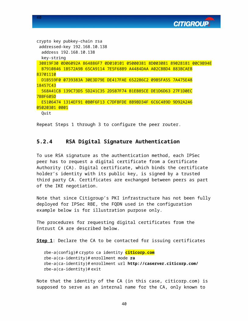
40
The additional fragmentation is considered part of the IPSec overhead. Even if path MTU discovery is activated on these routers, there is no way to eliminate this round of fragmentation for large packets. The effect, however, is local to the segment between IPSec peers.
40

41
7.2 Appendix B – IPSec Authentication Methods + ISR Routers
Assumptions
Citigroup IPSec Standards will be followed (Please refer to the IPSec Design Guide for more information) Target Code: 12.4(x) (Release Date: TBD/2006)**
Device Onboard Encryptor
AIM-VPN Card PSK RSA-encr RSA-sig(General Keys)
RSA-sig(CA)
1841 NOT USED UNDER
TEST
2811 NOT USED
3845Citigroup Standard IPSec Transform-
Set NOT SUPPORTED,
hence not recommended
(AIM-VPN/HPII-
PLUS)
NOT SUPPORTED
** 12.4(x) will be tested in the Warren Lab once Cisco comes out with a code.
41