iPro DAC Installation and Operation Manual Solutions/Manuals... · 026-1727 Rev 0 11-APR-2011 iPro...
48
026-1727 Rev 0 11-APR-2011 iPro DAC Installation and Operation Manual
Transcript of iPro DAC Installation and Operation Manual Solutions/Manuals... · 026-1727 Rev 0 11-APR-2011 iPro...
026-1727 Rev 0 11-APR-2011
iPro DAC Installation and
Operation Manual

Retail Solutions3240 Town Point Drive NW, Suite 100
Kennesaw, GA 30144
Phone: 770-425-2724Fax: 770-425-9319
ALL RIGHTS RESERVED.
The information contained in this manual has been carefully checked and is believed to be accurate. However, Com-puter Process Controls, Inc. assumes no responsibility for any inaccuracies that may be contained herein. In no event will Computer Process Controls, Inc. be liable for any direct, indirect, special, incidental, or consequential damages resulting from any defect or omission in this manual, even if advised of the possibility of such damages. In the interest of continued product development, Computer Process Controls, Inc. reserves the right to make improvements to this manual, and the products described herein, at any time without notice or obligation.

Table Of Contents1 INTRODUCTION.......................................................................................................................................................... 1
1.1. THE IPRO DAC’S I/O POINTS....................................................................................................................................... 11.2. INDEPENDENT SYSTEM CONTROL ................................................................................................................................ 1
2 MOUNTING AND POWERING ................................................................................................................................. 2
2.1. INSTALLATION .............................................................................................................................................................. 22.2. POWERING THE IPRO DAC........................................................................................................................................... 2
2.2.1. Choosing Transformer Sizes ................................................................................................................................. 22.2.2. iPro DAC Power Wiring ....................................................................................................................................... 22.2.3. Wire Types and Maximum Distances................................................................................................................... 3
3 THE MODBUS NETWORK ........................................................................................................................................ 4
3.1. WIRING TYPES.............................................................................................................................................................. 43.1.1. Daisy Chains ......................................................................................................................................................... 43.1.2. Network Addressing - Visograph .......................................................................................................................... 5
3.1.2.1. Connecting the Visograph .................................................................................................................................................. 53.1.2.2. Visograph Navigation ......................................................................................................................................................... 53.1.2.3. Setting the MODBUS Address ........................................................................................................................................... 5
3.2. MODBUS TERMINATION............................................................................................................................................. 6
4 INPUT AND OUTPUT SETUP .................................................................................................................................... 7
4.1. THE IPRO DAC INPUTS ............................................................................................................................................... 74.1.1. Wiring Analog Inputs on the iPro DAC ................................................................................................................ 84.1.2. Wiring Digital Inputs on the iPro DAC ................................................................................................................ 8
4.2. THE IPRO DAC OUTPUTS............................................................................................................................................. 94.2.1. Wiring Digital Loads on the iPro DAC .............................................................................................................. 104.2.2. Wiring Analog Outputs on the iPro DAC ........................................................................................................... 10
5 IPRO DAC STATUS LEDS ........................................................................................................................................ 12
5.1. PWR ON LED ........................................................................................................................................................... 125.2. TX AND RX LEDS ...................................................................................................................................................... 125.3. LED1 NETWORK STATUS........................................................................................................................................... 125.4. ALARM LED STATUS............................................................................................................................................... 12
6 SOFTWARE OVERVIEW ......................................................................................................................................... 13
6.1. APPLICATION MODE ................................................................................................................................................... 136.2. OPERATIONAL MODES................................................................................................................................................ 136.3. SPACE TEMPERATURE CONTROL................................................................................................................................ 13
6.3.1. Terminal Load Calculation................................................................................................................................. 136.4. SUPPLY TEMPERATURE CONTROL.............................................................................................................................. 14
6.4.1. Supply Air Setpoint Reset .................................................................................................................................... 146.4.2. Cooling Mode...................................................................................................................................................... 14
6.4.2.1. Staged Cooling.................................................................................................................................................................. 146.4.2.2. Modulating Cooling .......................................................................................................................................................... 146.4.2.3. Cooling OAT Lockout ...................................................................................................................................................... 15
6.4.3. Heating Mode...................................................................................................................................................... 156.4.3.1. Staged Heating .................................................................................................................................................................. 156.4.3.2. Modulating Heating .......................................................................................................................................................... 156.4.3.3. Heating OAT Lockout ...................................................................................................................................................... 16
Table of Contents • v
6.5. FAN CONTROL ............................................................................................................................................................ 166.5.1. CAV Mode ........................................................................................................................................................... 16
6.5.1.1. Variable-Speed Fan Control in CAV................................................................................................................................ 176.5.1.2. Single Speed with Bypass Damper ................................................................................................................................... 176.5.1.3. Variable-Speed Fan Control in VAV................................................................................................................................ 17
6.5.2. Fan Proofing ....................................................................................................................................................... 176.6. DEHUMIDIFICATION CONTROL.................................................................................................................................... 17
6.6.1. Enabling Dehumidification ................................................................................................................................. 186.6.1.1. Dehumidification Setpoint ................................................................................................................................................ 186.6.1.2. Dehumidification by Dewpoint ........................................................................................................................................ 186.6.1.3. Low Temperature Lockout ............................................................................................................................................... 18
6.6.2. Dehumidifying using Cool Stages ....................................................................................................................... 186.6.2.1. Digital Scroll Operation during Dehumidification ........................................................................................................... 18
6.6.3. Reheat Output...................................................................................................................................................... 196.6.4. Primary Heat Used as Reheat............................................................................................................................. 196.6.5. Return Air Bypass Damper ................................................................................................................................. 19
6.6.5.1. Return Air Damper during Dehumidification................................................................................................................... 196.7. OUTSIDE AIR CONTROL.............................................................................................................................................. 19
6.7.1. Indoor Air Quality............................................................................................................................................... 196.7.2. Make-up Air Control ........................................................................................................................................... 196.7.3. Economizer Control ............................................................................................................................................ 20
6.7.3.1. Operation of Two-Position Dampers During Economization .......................................................................................... 206.7.3.2. Operation of Variable-Position Dampers During Economization .................................................................................... 206.7.3.3. Economization Enabling Strategy .................................................................................................................................... 20
6.7.4. Smoke Detection.................................................................................................................................................. 216.7.5. Priority When Economization, CO2 Control, and Make-up Air are Used Together.......................................... 216.7.6. Return Damper Control ...................................................................................................................................... 21
6.8. 6.10 REVERSING VALVE CONTROL ............................................................................................................................ 216.9. STANDALONE FUNCTIONALITY................................................................................................................................... 216.10. CONTROL TEMPERATURE SENSOR FAILURES ........................................................................................................... 21
7 E2 SETUP ..................................................................................................................................................................... 23
7.1. NETWORK CONNECTION TO E2 ................................................................................................................................. 237.1.1. Setup Network Ports............................................................................................................................................ 24
7.2. ADD AND CONNECT IPRO DACS................................................................................................................................ 247.3. VIEWING THE IPRO DAC STATUS SCREEN................................................................................................................. 26
8 CONNECTIONS .......................................................................................................................................................... 27
8.1. IPRO DAC CONNECTOR DESCRIPTIONS .................................................................................................................... 278.2. TERMINAL NUMBER DESCRIPTIONS ........................................................................................................................... 288.3. TECHNICAL SPECIFICATIONS ...................................................................................................................................... 31
8.3.1. Analog Inputs ..................................................................................................................................................... 318.3.2. Digital Inputs ...................................................................................................................................................... 318.3.3. Analog Outputs ................................................................................................................................................... 318.3.4. Digital Outputs ................................................................................................................................................... 32
8.4. WIRING ....................................................................................................................................................................... 33
9 USING THE VISOGRAPH......................................................................................................................................... 34
9.1. VIEWING STATUS........................................................................................................................................................ 349.1.1. Input Status.......................................................................................................................................................... 349.1.2. Output Status ....................................................................................................................................................... 349.1.3. VAV Fan Status ................................................................................................................................................... 34
9.2. VIEWING I/O CONFIGURATION ................................................................................................................................... 349.2.1. Analog Inputs ...................................................................................................................................................... 349.2.2. Relay Outputs ...................................................................................................................................................... 35
vi • iPro DAC Manual 026-1727 Rev 0 11-APR-2011
9.2.3. Analog Outputs ................................................................................................................................................... 359.2.4. Digital Inputs ...................................................................................................................................................... 35
9.3. RELAY OUTPUT OVERRIDES WITH VISOGRAPH.......................................................................................................... 359.3.1. Analog Output Overrides with Visograph .......................................................................................................... 36
9.3.1.1. To Override an Analog Output ......................................................................................................................................... 369.3.1.2. To Clear an Analog Output Override ............................................................................................................................... 36
INDEX............................................................................................................................................................................. 39
Table of Contents • vii

1 Introduction
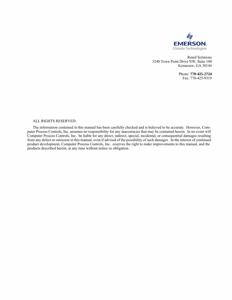
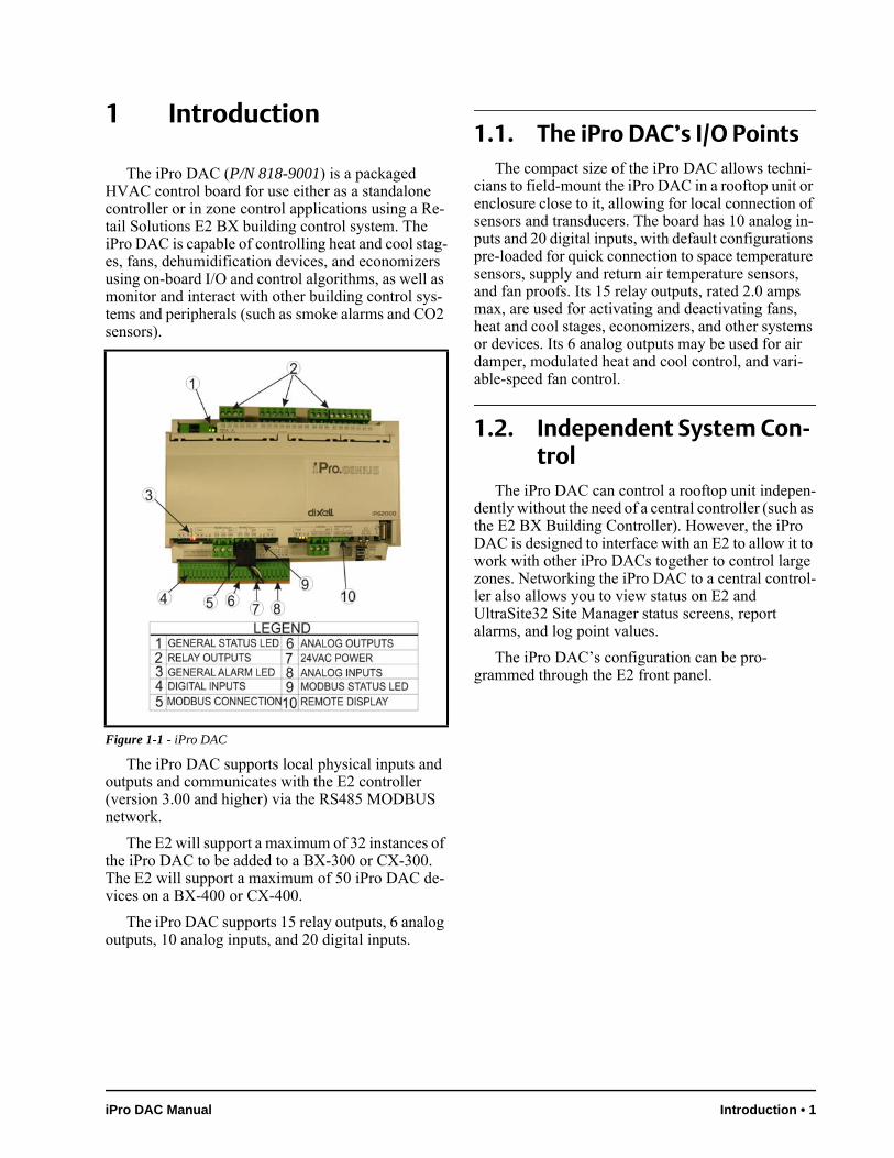
The iPro DAC (P/N 818-9001) is a packaged HVAC control board for use either as a standalone controller or in zone control applications using a Re-tail Solutions E2 BX building control system. The iPro DAC is capable of controlling heat and cool stag-es, fans, dehumidification devices, and economizers using on-board I/O and control algorithms, as well as monitor and interact with other building control sys-tems and peripherals (such as smoke alarms and CO2 sensors).
The iPro DAC supports local physical inputs and outputs and communicates with the E2 controller (version 3.00 and higher) via the RS485 MODBUS network.
The E2 will support a maximum of 32 instances of the iPro DAC to be added to a BX-300 or CX-300. The E2 will support a maximum of 50 iPro DAC de-vices on a BX-400 or CX-400.
The iPro DAC supports 15 relay outputs, 6 analog outputs, 10 analog inputs, and 20 digital inputs.
1.1. The iPro DAC’s I/O PointsThe compact size of the iPro DAC allows techni-
cians to field-mount the iPro DAC in a rooftop unit or enclosure close to it, allowing for local connection of sensors and transducers. The board has 10 analog in-puts and 20 digital inputs, with default configurations pre-loaded for quick connection to space temperature sensors, supply and return air temperature sensors, and fan proofs. Its 15 relay outputs, rated 2.0 amps max, are used for activating and deactivating fans, heat and cool stages, economizers, and other systems or devices. Its 6 analog outputs may be used for air damper, modulated heat and cool control, and vari-able-speed fan control.
1.2. Independent System Con-trol
The iPro DAC can control a rooftop unit indepen-dently without the need of a central controller (such as the E2 BX Building Controller). However, the iPro DAC is designed to interface with an E2 to allow it to work with other iPro DACs together to control large zones. Networking the iPro DAC to a central control-ler also allows you to view status on E2 and UltraSite32 Site Manager status screens, report alarms, and log point values.
The iPro DAC’s configuration can be pro-grammed through the E2 front panel.
Figure 1-1 - iPro DAC
iPro DAC Manual Introduction • 1
2 Mounting and Power-ing
The iPro DAC is usually mounted by the HVAC equipment manufacturer. Therefore, the installer need only make the necessary connections between the boards and the site controller(s).
In some instances, an installer may be required to mount the iPro DAC. There are no restrictions on the location of the iPro DAC; however, the controller
should be mounted in a location protected from mois-ture. Typically, mounting inside the electrical control panel of a package unit is acceptable. If there is no room to mount the controller inside the HVAC unit, it may be mounted inside a weatherproof enclosure on the outside of the unit.
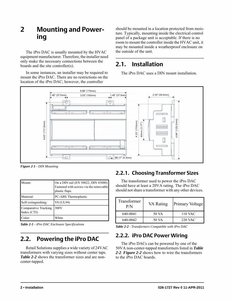
2.1. InstallationThe iPro DAC uses a DIN mount installation.
2.2. Powering the iPro DACRetail Solutions supplies a wide variety of 24VAC
transformers with varying sizes without center taps. Table 2-2 shows the transformer sizes and are non-center-tapped.
2.2.1. Choosing Transformer SizesThe transformer used to power the iPro DAC
should have at least a 20VA rating. The iPro DAC should not share a transformer with any other devices.
2.2.2. iPro DAC Power WiringThe iPro DACs can be powered by one of the
50VA non-center-tapped transformers listed in Table 2-2. Figure 2-2 shows how to wire the transformers to the iPro DAC boards.
Figure 2-1 - DIN Mounting
Mount: On a DIN rail (EN 50022, DIN 43880)Fastened with screws via the removable plastic flaps.
Material: PC-ABS Thermoplastic
Self-extinguishing: V0 (UL94)
Comparative Tracking Index (CTI):
300V
Color: White
Table 2-1 - iPro DAC Enclosure Specifications
Transformer P/N
VA Rating Primary Voltage
640-0041 50 VA 110 VAC
640-0042 50 VA 220 VAC
Table 2-2 - Transformers Compatible with iPro DAC
2 • Installation 026-1727 Rev 0 11-APR-2011
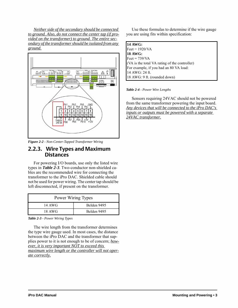
Neither side of the secondary should be connected to ground. Also, do not connect the center tap (if pro-vided on the transformer) to ground. The entire sec-ondary of the transformer should be isolated from any ground.
2.2.3. Wire Types and Maximum Distances
For powering I/O boards, use only the listed wire types in Table 2-3. Two-conductor non-shielded ca-bles are the recommended wire for connecting the transformer to the iPro DAC. Shielded cable should not be used for power wiring. The center tap should be left disconnected, if present on the transformer.
The wire length from the transformer determines the type wire gauge used. In most cases, the distance between the iPro DAC and the transformer that sup-plies power to it is not enough to be of concern; how-ever, it is very important NOT to exceed this maximum wire length or the controller will not oper-ate correctly.
Use these formulas to determine if the wire gauge you are using fits within specification:
Sensors requiring 24VAC should not be powered from the same transformer powering the input board. Any devices that will be connected to the iPro DAC's inputs or outputs must be powered with a separate 24VAC transformer.
Figure 2-2 - Non-Center-Tapped Transformer Wiring
Power Wiring Types
14 AWG Belden 9495
18 AWG Belden 9495
Table 2-3 - Power Wiring Types
14 AWG:Feet = 1920/VA18 AWG:Feet = 739/VA(VA is the total VA rating of the controller)For example, if you had an 80 VA load:14 AWG: 24 ft.18 AWG: 9 ft. (rounded down)
Table 2-4 - Power Wire Lengths
iPro DAC Manual Mounting and Powering • 3
3 The MODBUS Network
Although the iPro DAC can operate as a stand-alone controller, it relies on an E2 unit for advanced features such as remote dial-in/dial-out, logging, and alarm control. The iPro DAC uses an RS485 network connection to communicate with E2 site controllers.
3.1. Wiring TypesRetail Solutions specs Belden #8761 shielded
twisted pair cables for use as MODBUS wiring (or Belden #82761 and Belden #88761 for plenum instal-lations).
If the recommended cable is not available in your area, be sure the wiring meets or exceeds the follow-ing specs:
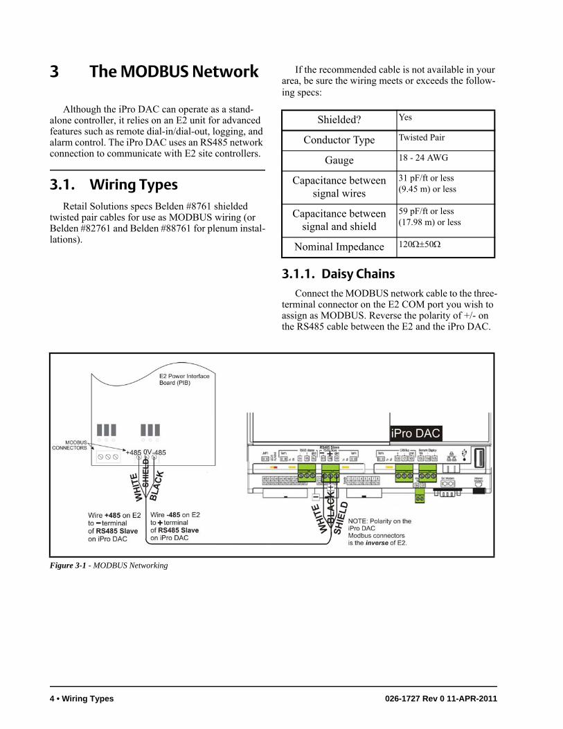
3.1.1. Daisy ChainsConnect the MODBUS network cable to the three-
terminal connector on the E2 COM port you wish to assign as MODBUS. Reverse the polarity of +/- on the RS485 cable between the E2 and the iPro DAC.
Shielded? Yes
Conductor Type Twisted Pair
Gauge 18 - 24 AWG
Capacitance between signal wires
31 pF/ft or less(9.45 m) or less
Capacitance between signal and shield
59 pF/ft or less(17.98 m) or less
Nominal Impedance 12050
Figure 3-1 - MODBUS Networking
4 • Wiring Types 026-1727 Rev 0 11-APR-2011
3.1.2. Network Addressing - Viso-graph
The network address makes a board unique from other boards on the network of the same type. This al-lows the site controller to find it and communicate with it easily.
The network address of the iPro DAC is set using add-on devices called visographs (P/N 318-7272).
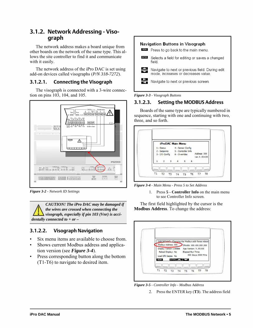
3.1.2.1. Connecting the Visograph
The visograph is connected with a 3-wire connec-tion on pins 103, 104, and 105.
3.1.2.2. Visograph Navigation
• Six menu items are available to choose from.• Shows current Modbus address and applica-
tion version (see Figure 3-4).• Press corresponding button along the bottom
(T1-T6) to navigate to desired item.
3.1.2.3. Setting the MODBUS Address
Boards of the same type are typically numbered in sequence, starting with one and continuing with two, three, and so forth.
1. Press 5 - Controller Info on the main menu to see Controller Info screen.
The first field highlighted by the cursor is the Modbus Address. To change the address:
2. Press the ENTER key (T3). The address field
Figure 3-2 - Network ID Settings
CAUTION! The iPro DAC may be damaged if the wires are crossed when connecting the visograph, especially if pin 103 (Vnr) is acci-
dentally connected to + or –
Figure 3-3 - Visograph Buttons
Figure 3-4 - Main Menu - Press 5 to Set Address
Figure 3-5 - Controller Info - Modbus Address
iPro DAC Manual The MODBUS Network • 5
should start blinking.
3. Using the UP and DOWN arrows (T4 and T5), change the address to the desired value.
4. Press ENTER to save new address.The ad-dress field should stop blinking.
5. Press MENU (T1) to go back to main menu.
3.1.2.3.1. Versions
The iPro DAC and Visograph versions are also shown on the Controller Info screen.
If the Visograph version shown is not the most re-cent, set the Reload Display field to Yes. This will cause the display to download the latest screens con-tained in the iPro DAC.
3.2. MODBUS TerminationThe iPro DAC has on-board termination capabili-
ty. A single termination jumper is located next to the RS485 slave connector. If the iPro DAC is located at the physical end of the modbus network, the termina-tion jumper should be applied.
NOTE: When the MODBUS address is changed, the iPro DAC will automatically re-boot.
6 • MODBUS Termination 026-1727 Rev 0 11-APR-2011
4 Input and Output Setup
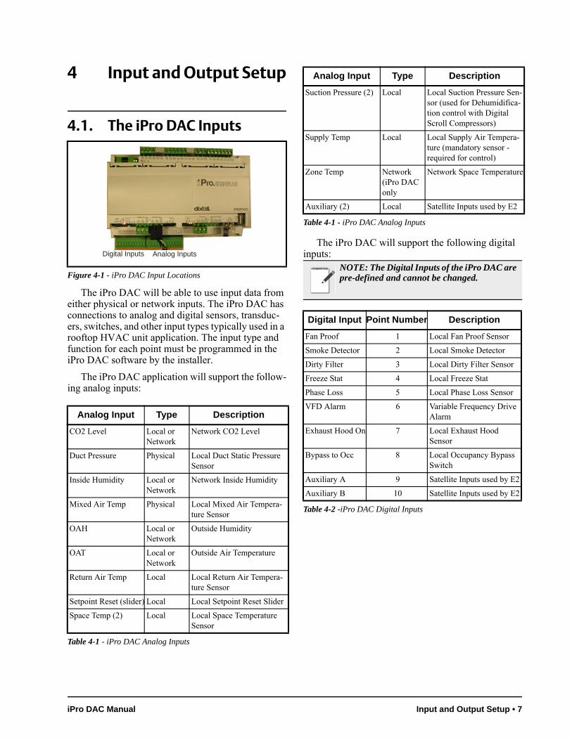
4.1. The iPro DAC Inputs
The iPro DAC will be able to use input data from either physical or network inputs. The iPro DAC has connections to analog and digital sensors, transduc-ers, switches, and other input types typically used in a rooftop HVAC unit application. The input type and function for each point must be programmed in the iPro DAC software by the installer.
The iPro DAC application will support the follow-ing analog inputs:
The iPro DAC will support the following digital inputs:
Figure 4-1 - iPro DAC Input Locations
Analog Input Type Description
CO2 Level Local or Network
Network CO2 Level
Duct Pressure Physical Local Duct Static Pressure Sensor
Inside Humidity Local or Network
Network Inside Humidity
Mixed Air Temp Physical Local Mixed Air Tempera-ture Sensor
OAH Local or Network
Outside Humidity
OAT Local or Network
Outside Air Temperature
Return Air Temp Local Local Return Air Tempera-ture Sensor
Setpoint Reset (slider) Local Local Setpoint Reset Slider
Space Temp (2) Local Local Space Temperature Sensor
Table 4-1 - iPro DAC Analog Inputs
Analog InputsDigital Inputs
Suction Pressure (2) Local Local Suction Pressure Sen-sor (used for Dehumidifica-tion control with Digital Scroll Compressors)
Supply Temp Local Local Supply Air Tempera-ture (mandatory sensor - required for control)
Zone Temp Network (iPro DAC only
Network Space Temperature
Auxiliary (2) Local Satellite Inputs used by E2
NOTE: The Digital Inputs of the iPro DAC are pre-defined and cannot be changed.
Digital Input Point Number Description
Fan Proof 1 Local Fan Proof Sensor
Smoke Detector 2 Local Smoke Detector
Dirty Filter 3 Local Dirty Filter Sensor
Freeze Stat 4 Local Freeze Stat
Phase Loss 5 Local Phase Loss Sensor
VFD Alarm 6 Variable Frequency Drive Alarm
Exhaust Hood On 7 Local Exhaust Hood Sensor
Bypass to Occ 8 Local Occupancy Bypass Switch
Auxiliary A 9 Satellite Inputs used by E2
Auxiliary B 10 Satellite Inputs used by E2
Table 4-2 -iPro DAC Digital Inputs
Analog Input Type Description
Table 4-1 - iPro DAC Analog Inputs
iPro DAC Manual Input and Output Setup • 7
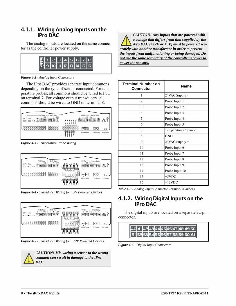
4.1.1. Wiring Analog Inputs on the iPro DAC
The analog inputs are located on the same connec-tor as the controller power supply.
The iPro DAC provides separate input commons depending on the type of sensor connected. For tem-perature probes, all commons should be wired to PbC on terminal 7. For voltage output transducers, all commons should be wired to GND on terminal 8.
4.1.2. Wiring Digital Inputs on the iPro DAC
The digital inputs are located on a separate 22-pin connector.
Figure 4-2 - Analog Input Connectors
Figure 4-3 - Temperature Probe Wiring
Figure 4-4 - Transducer Wiring for +5V Powered Devices
Figure 4-5 - Transducer Wiring for +12V Powered Devices
CAUTION! Mis-wiring a sensor to the wrong common can result in damage to the iPro DAC.
CAUTION! Any inputs that are powered with a voltage that differs from that supplied by the iPro DAC (+12V or +5V) must be powered sep-
arately with another transformer in order to prevent the inputs from malfunctioning or being damaged. Do not use the same secondary of the controller's power to power the sensors.
Terminal Number on Connector
Name
1 24VAC Supply -
2 Probe Input 1
3 Probe Input 2
4 Probe Input 3
5 Probe Input 4
6 Probe Input 5
7 Temperature Common
8 GND
9 24VAC Supply +
10 Probe Input 6
11 Probe Input 7
12 Probe Input 8
13 Probe Input 9
14 Probe Input 10
15 +5VDC
16 +12VDC
Table 4-3 - Analog Input Connector Terminal Numbers
Figure 4-6 - Digital Input Connectors
8 • The iPro DAC Inputs 026-1727 Rev 0 11-APR-2011
The iPro DAC provides a maximum of 20 opto-in-sulated digital inputs. However, only the first ten in-puts are currently used (see Table 4-2). All digital inputs are voltage-free and are intended to have dry contact devices connected.
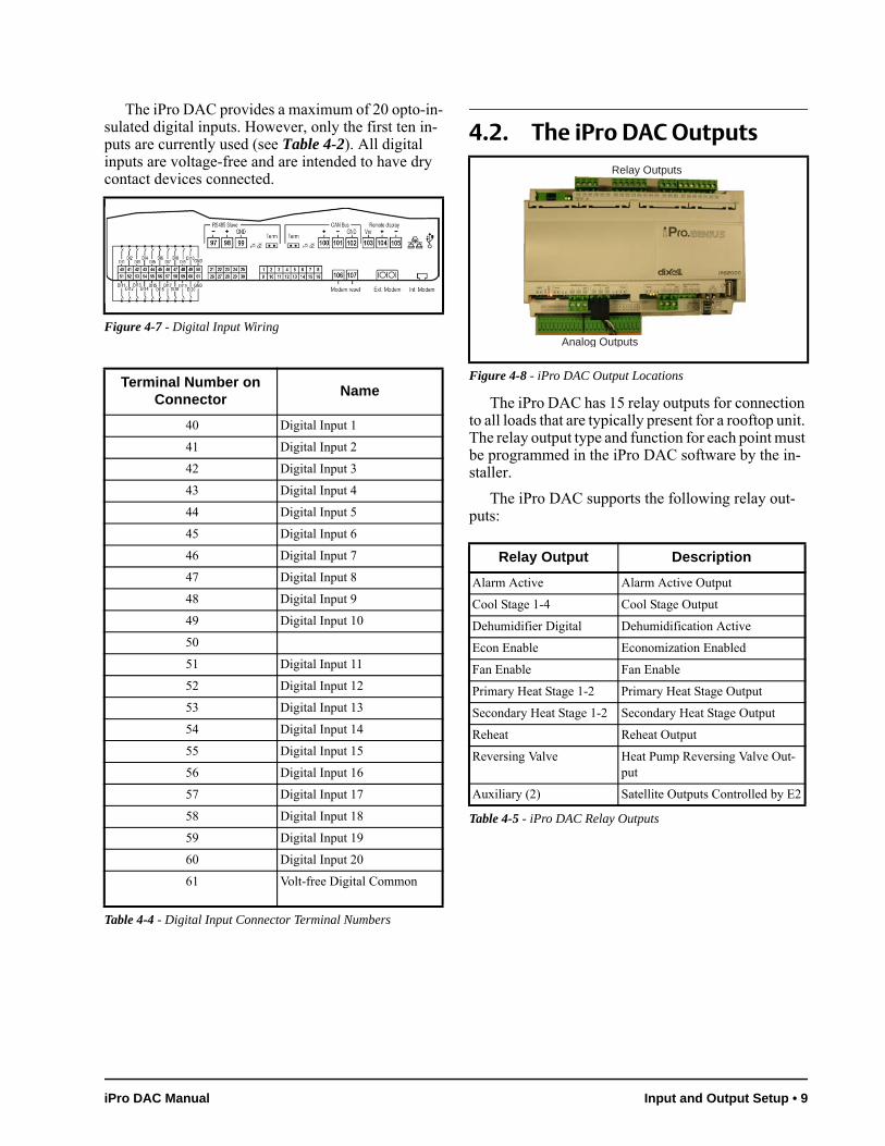
4.2. The iPro DAC Outputs
The iPro DAC has 15 relay outputs for connection to all loads that are typically present for a rooftop unit. The relay output type and function for each point must be programmed in the iPro DAC software by the in-staller.
The iPro DAC supports the following relay out-puts:
Figure 4-7 - Digital Input Wiring
Terminal Number on Connector
Name
40 Digital Input 1
41 Digital Input 2
42 Digital Input 3
43 Digital Input 4
44 Digital Input 5
45 Digital Input 6
46 Digital Input 7
47 Digital Input 8
48 Digital Input 9
49 Digital Input 10
50
51 Digital Input 11
52 Digital Input 12
53 Digital Input 13
54 Digital Input 14
55 Digital Input 15
56 Digital Input 16
57 Digital Input 17
58 Digital Input 18
59 Digital Input 19
60 Digital Input 20
61 Volt-free Digital Common
Table 4-4 - Digital Input Connector Terminal Numbers
Figure 4-8 - iPro DAC Output Locations
Relay Output Description
Alarm Active Alarm Active Output
Cool Stage 1-4 Cool Stage Output
Dehumidifier Digital Dehumidification Active
Econ Enable Economization Enabled
Fan Enable Fan Enable
Primary Heat Stage 1-2 Primary Heat Stage Output
Secondary Heat Stage 1-2 Secondary Heat Stage Output
Reheat Reheat Output
Reversing Valve Heat Pump Reversing Valve Out-put
Auxiliary (2) Satellite Outputs Controlled by E2
Table 4-5 - iPro DAC Relay Outputs
Analog Outputs
Relay Outputs
iPro DAC Manual Input and Output Setup • 9
The iPro DAC supports the following analog out-puts:
For both relay and analog outputs, the iPro DAC will drive physical points as well as send the current output value over Modbus to E2.
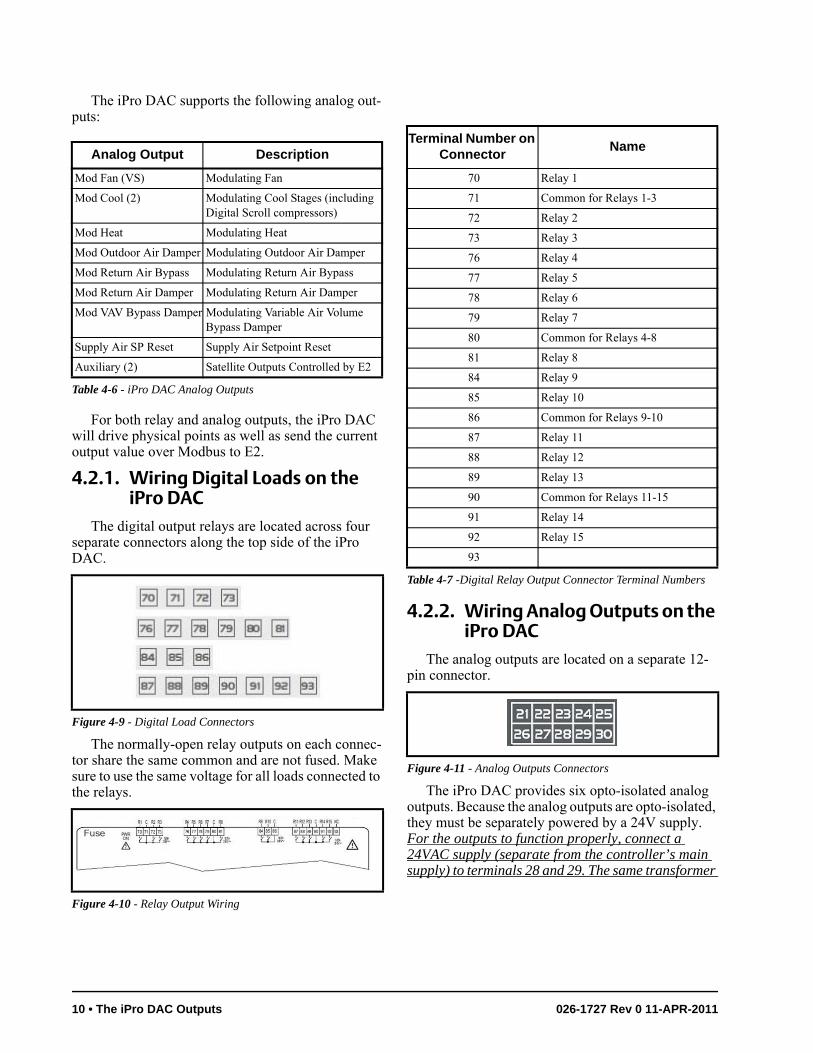
4.2.1. Wiring Digital Loads on the iPro DAC
The digital output relays are located across four separate connectors along the top side of the iPro DAC.
The normally-open relay outputs on each connec-tor share the same common and are not fused. Make sure to use the same voltage for all loads connected to the relays.
4.2.2. Wiring Analog Outputs on the iPro DAC
The analog outputs are located on a separate 12-pin connector.
The iPro DAC provides six opto-isolated analog outputs. Because the analog outputs are opto-isolated, they must be separately powered by a 24V supply. For the outputs to function properly, connect a 24VAC supply (separate from the controller’s main supply) to terminals 28 and 29. The same transformer
Analog Output Description
Mod Fan (VS) Modulating Fan
Mod Cool (2) Modulating Cool Stages (including Digital Scroll compressors)
Mod Heat Modulating Heat
Mod Outdoor Air Damper Modulating Outdoor Air Damper
Mod Return Air Bypass Modulating Return Air Bypass
Mod Return Air Damper Modulating Return Air Damper
Mod VAV Bypass Damper Modulating Variable Air Volume Bypass Damper
Supply Air SP Reset Supply Air Setpoint Reset
Auxiliary (2) Satellite Outputs Controlled by E2
Table 4-6 - iPro DAC Analog Outputs
Figure 4-9 - Digital Load Connectors
Figure 4-10 - Relay Output Wiring
Terminal Number on Connector
Name
70 Relay 1
71 Common for Relays 1-3
72 Relay 2
73 Relay 3
76 Relay 4
77 Relay 5
78 Relay 6
79 Relay 7
80 Common for Relays 4-8
81 Relay 8
84 Relay 9
85 Relay 10
86 Common for Relays 9-10
87 Relay 11
88 Relay 12
89 Relay 13
90 Common for Relays 11-15
91 Relay 14
92 Relay 15
93
Table 4-7 -Digital Relay Output Connector Terminal Numbers
Figure 4-11 - Analog Outputs Connectors
10 • The iPro DAC Outputs 026-1727 Rev 0 11-APR-2011
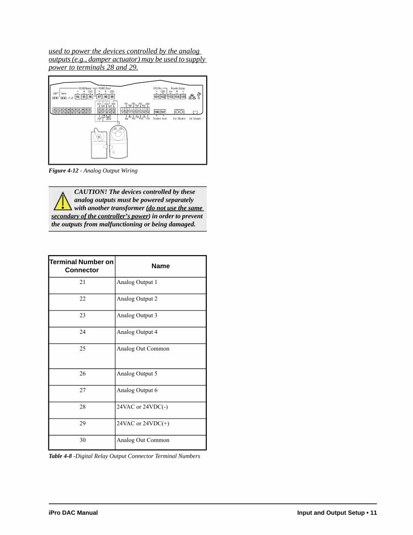
used to power the devices controlled by the analog outputs (e.g., damper actuator) may be used to supply power to terminals 28 and 29.
Figure 4-12 - Analog Output Wiring
CAUTION! The devices controlled by these analog outputs must be powered separately with another transformer (do not use the same
secondary of the controller’s power) in order to prevent the outputs from malfunctioning or being damaged.
Terminal Number on Connector
Name
21 Analog Output 1
22 Analog Output 2
23 Analog Output 3
24 Analog Output 4
25 Analog Out Common
26 Analog Output 5
27 Analog Output 6
28 24VAC or 24VDC(-)
29 24VAC or 24VDC(+)
30 Analog Out Common
Table 4-8 -Digital Relay Output Connector Terminal Numbers
iPro DAC Manual Input and Output Setup • 11
5 iPro DAC Status LEDs
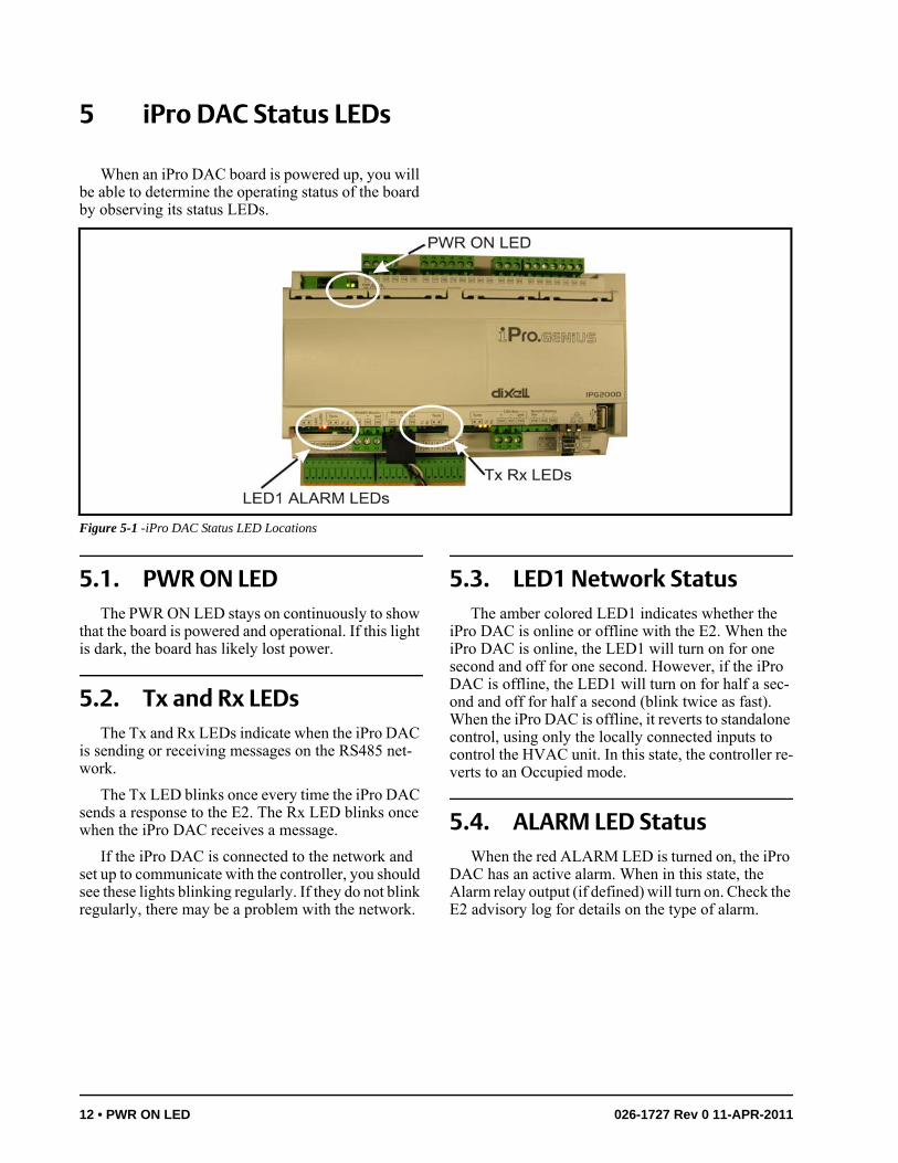
When an iPro DAC board is powered up, you will be able to determine the operating status of the board by observing its status LEDs.
5.1. PWR ON LEDThe PWR ON LED stays on continuously to show
that the board is powered and operational. If this light is dark, the board has likely lost power.
5.2. Tx and Rx LEDsThe Tx and Rx LEDs indicate when the iPro DAC
is sending or receiving messages on the RS485 net-work.
The Tx LED blinks once every time the iPro DAC sends a response to the E2. The Rx LED blinks once when the iPro DAC receives a message.
If the iPro DAC is connected to the network and set up to communicate with the controller, you should see these lights blinking regularly. If they do not blink regularly, there may be a problem with the network.
5.3. LED1 Network StatusThe amber colored LED1 indicates whether the
iPro DAC is online or offline with the E2. When the iPro DAC is online, the LED1 will turn on for one second and off for one second. However, if the iPro DAC is offline, the LED1 will turn on for half a sec-ond and off for half a second (blink twice as fast). When the iPro DAC is offline, it reverts to standalone control, using only the locally connected inputs to control the HVAC unit. In this state, the controller re-verts to an Occupied mode.
5.4. ALARM LED StatusWhen the red ALARM LED is turned on, the iPro
DAC has an active alarm. When in this state, the Alarm relay output (if defined) will turn on. Check the E2 advisory log for details on the type of alarm.
Figure 5-1 -iPro DAC Status LED Locations
12 • PWR ON LED 026-1727 Rev 0 11-APR-2011
6 Software OverviewThe iPro DAC maintains space temperature set-
points by modulating heating or cooling stages to maintain a desired supply air temperature. For this reason, a supply air temperature sensor must be con-nected to the controller. The desired supply air tem-perature is primarily determined by a setpoint and can be automatically adjusted based on changes in build-ing load.
6.1. Application ModeThe iPro DAC supports packaged HVAC control
in either Constant Air Volume (CAV) or Variable Air Volume (VAV) applications. The main difference be-tween the two modes is how the variable speed fan will be controlled. When CAV is selected, the vari-able speed fan is modulated based on the number of heating or cooling stages that are currently active.
When VAV is selected, the variable speed fan modu-lates to maintain a static duct pressure. See Section 6.5., Fan Control for more details.
Also, VAV mode does not require a local space sensor to be connected to the controller. Instead, the system terminal load is calculated by the E2 and is sent over the network to the iPro DAC so the opera-tional mode can be determined. Note that the primary control of heating and cooling stages using the supply air temperature sensor is identical for either CAV or VAV mode.
6.2. Operational ModesThe iPro DAC will be in one of nine possible
modes of operation at any given time. All modes have different priorities so if conditions warrant two modes to be operational at the same time, one of the modes will win and become active. In the table, the modes are shown in ascending priority, i.e., Idle is the lowest priority and Emergency Shutdown is the highest pri-ority.
6.3. Space Temperature Con-trol
There are two active space temperature setpoints in an iPro DAC: a cooling setpoint and a heating set-point. In general, when the input rises above the cool-ing setpoint, cooling mode begins, and when the input falls below the heating setpoint, heating mode begins.
6.3.1. Terminal Load CalculationAs the space temperature rises above the active
cooling setpoint, or falls below the active heating set-point, the system’s terminal load will increase, either positively for cooling, or negatively for heating. The
Operating Mode Description Outputs Active
Idle Default mode if no other modes are active None
Ventilation Space air recirculation only Indoor Fan
CO2 Purge Max CO2 level reached and fresh air must be brought in to building
Indoor Fan, Outdoor Air Damper
Economizing Outdoor air free cooling active Indoor Fan, Outdoor Air Damper
Make-up Air Exhaust Fan detected and make-up air must be brought in to building
Indoor Fan, Outdoor Air Damper
Heating Heating is active Indoor Fan, Heat Stages, Modulating Heat
Cooling Cooling is active Indoor Fan, Cool Stages (Fixed or Modulat-ing),
Dehum Dehumidification is active Indoor Fan, Cool Stages or Dehum Output, Reheat Output
Emergency Shutdown One of the following is active: Smoke Detected, Phase Loss Active, Fan Proof Failure
None
Table 6-1 - iPro DAC Operational Modes
iPro DAC Manual Software Overview • 13
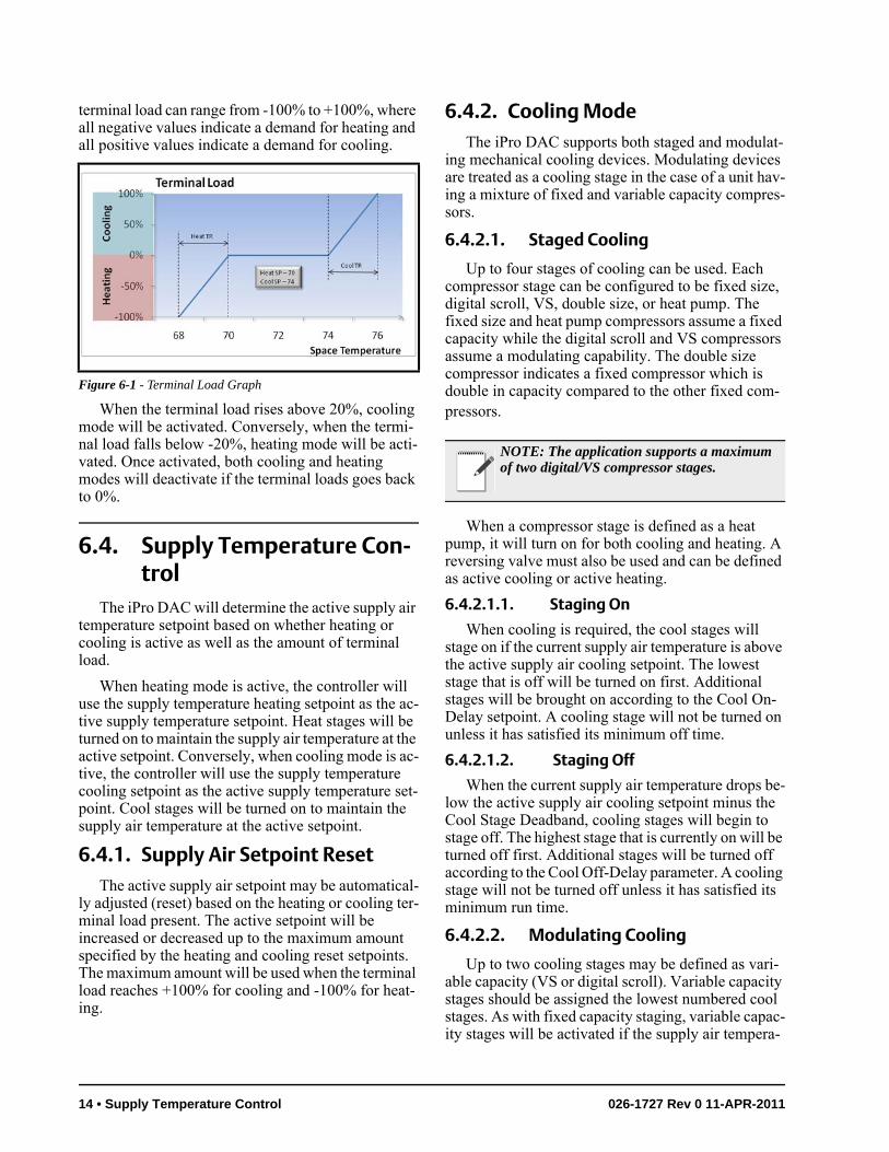
terminal load can range from -100% to +100%, where all negative values indicate a demand for heating and all positive values indicate a demand for cooling.
When the terminal load rises above 20%, cooling mode will be activated. Conversely, when the termi-nal load falls below -20%, heating mode will be acti-vated. Once activated, both cooling and heating modes will deactivate if the terminal loads goes back to 0%.
6.4. Supply Temperature Con-trol
The iPro DAC will determine the active supply air temperature setpoint based on whether heating or cooling is active as well as the amount of terminal load.
When heating mode is active, the controller will use the supply temperature heating setpoint as the ac-tive supply temperature setpoint. Heat stages will be turned on to maintain the supply air temperature at the active setpoint. Conversely, when cooling mode is ac-tive, the controller will use the supply temperature cooling setpoint as the active supply temperature set-point. Cool stages will be turned on to maintain the supply air temperature at the active setpoint.
6.4.1. Supply Air Setpoint ResetThe active supply air setpoint may be automatical-
ly adjusted (reset) based on the heating or cooling ter-minal load present. The active setpoint will be increased or decreased up to the maximum amount specified by the heating and cooling reset setpoints. The maximum amount will be used when the terminal load reaches +100% for cooling and -100% for heat-ing.
6.4.2. Cooling ModeThe iPro DAC supports both staged and modulat-
ing mechanical cooling devices. Modulating devices are treated as a cooling stage in the case of a unit hav-ing a mixture of fixed and variable capacity compres-sors.
6.4.2.1. Staged Cooling
Up to four stages of cooling can be used. Each compressor stage can be configured to be fixed size, digital scroll, VS, double size, or heat pump. The fixed size and heat pump compressors assume a fixed capacity while the digital scroll and VS compressors assume a modulating capability. The double size compressor indicates a fixed compressor which is double in capacity compared to the other fixed com-pressors.
When a compressor stage is defined as a heat pump, it will turn on for both cooling and heating. A reversing valve must also be used and can be defined as active cooling or active heating.
6.4.2.1.1. Staging On
When cooling is required, the cool stages will stage on if the current supply air temperature is above the active supply air cooling setpoint. The lowest stage that is off will be turned on first. Additional stages will be brought on according to the Cool On-Delay setpoint. A cooling stage will not be turned on unless it has satisfied its minimum off time.
6.4.2.1.2. Staging Off
When the current supply air temperature drops be-low the active supply air cooling setpoint minus the Cool Stage Deadband, cooling stages will begin to stage off. The highest stage that is currently on will be turned off first. Additional stages will be turned off according to the Cool Off-Delay parameter. A cooling stage will not be turned off unless it has satisfied its minimum run time.
6.4.2.2. Modulating Cooling
Up to two cooling stages may be defined as vari-able capacity (VS or digital scroll). Variable capacity stages should be assigned the lowest numbered cool stages. As with fixed capacity staging, variable capac-ity stages will be activated if the supply air tempera-
Figure 6-1 - Terminal Load Graph
NOTE: The application supports a maximum of two digital/VS compressor stages.
14 • Supply Temperature Control 026-1727 Rev 0 11-APR-2011
ture is above the active supply air cooling setpoint. However, the next higher stage after a variable capac-ity stage will start its On-Delay only after the variable stage is at its maximum capacity. Likewise, the next lower stage before a variable capacity stage will start its Off-Delay only after the variable stage is at its min-imum capacity.
When a variable capacity compressor is activated, it will modulate to maintain the supply air tempera-ture at the active supply air cooling setpoint. A PID loop will be used to determine the capacity output.
If the first two stages are both variable capacity compressors, the lower stage will turn on first and ramp up. When the second modulating stage is acti-vated, the first modulating stage will remain at its maximum percent while the PID loop controls the second modulating stage. Once the second modulat-ing stage has turned off, the first modulating stage will be allowed to modulate again.
The variable capacity compressors have both min-imum and maximum capacity setpoints. In the case of multiple modulating stages, all stages will use the same minimum and maximum settings.
6.4.2.3. Cooling OAT Lockout
Cooling will only be allowed when the outside air temperature is above the cooling lockout temperature setpoint. If the outside temperature falls below this setpoint, cooling will be deactivated. Cooling will only be re-enabled when the outside temperature rises back above the lockout setpoint plus 2°F.
6.4.3. Heating ModeThe iPro DAC supports both staged and modulat-
ing mechanical heating devices. A modulating device, such as a hot water valve, is treated as a heating stage in the case of a unit having a mixture of fixed and modulating heating sources.
6.4.3.1. Staged Heating
Up to two stages of primary heating and two stages of secondary heating can be defined for a total of four heating stages. Lower operating cost heat stages, e.g., reclaim heat, should be connected to the primary heat outputs on the controller. Higher operating cost heat stages, e.g., gas or electric heat, should be connected to the secondary heat outputs. The controller will al-ways activate all primary heat sources before activat-ing secondary heat sources.
6.4.3.1.1. Staging On
When heating is required, the heat stages will stage on if the supply air temperature is below the ac-tive supply air heating setpoint. The lowest primary heat stage that is off will be turned on first. Additional primary stages will be brought on according to the Heat On-Delay setpoint as long as the supply temper-ature remains below the active supply temperature heating setpoint. A heating stage will not be turned on unless it has satisfied its minimum off time. Once all primary heating stages are on, secondary heating stag-es will begin to stage on in the same manner as the pri-mary heating stages.
6.4.3.1.2. Staging Off
When the supply air temperature rises above the active supply air heating setpoint plus the Heat Stage Deadband, heating stages will begin to stage off. The highest active secondary heating stage will be turned off first. Additional secondary stages will be turned off according to the Heat Off-Delay setpoint as long as the supply temperature remains above the supply temperature heating setpoint plus the Heat Stage Deadband. A heating stage will not be turned off un-less it has satisfied its minimum run time as specified by the parameter Heat Min On. Once all secondary heating stages are off, primary heating stages will be-gin to stage off in the same manner as the secondary heating stages.
6.4.3.2. Modulating Heating
In addition to the primary and secondary heat stag-es, the iPro DAC supports one modulating heating output. This modulating output must be classified as either a primary or secondary heat source.
6.4.3.2.1. Primary Mod Heat
If the modulating heat output is classified as a pri-mary heating source, it will be activated before any other primary heat stages when the application calls for heating. Once activated, the modulating heat out-put will modulate to maintain the supply air tempera-ture at the active supply air heating setpoint. A PID loop will be used to determine the capacity output. If the modulating heat output reaches 100% and remains there for the Heat On-Delay period, the first primary heating stage will be activated. Additional primary heating stages will be brought on according to the Heat On-Delay as long as the modulating heating out-put remains at 100%. No additional stages of heating will be brought on while the modulating heat output is
iPro DAC Manual Software Overview • 15
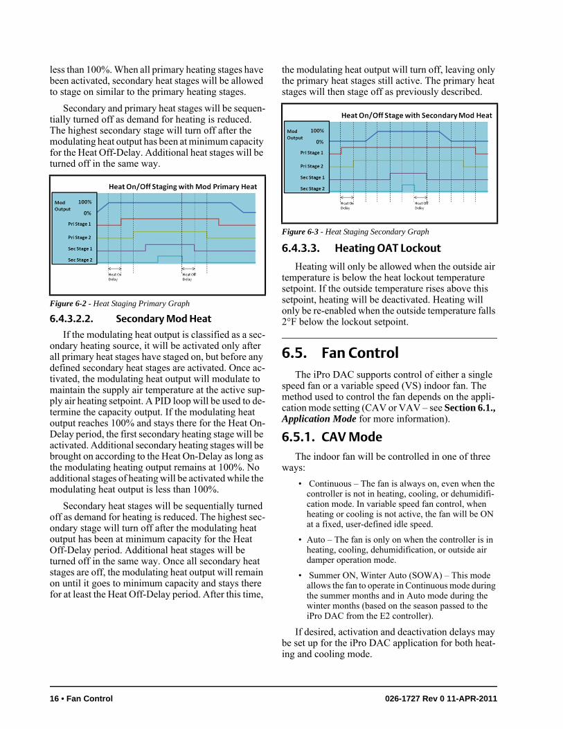
less than 100%. When all primary heating stages have been activated, secondary heat stages will be allowed to stage on similar to the primary heating stages.
Secondary and primary heat stages will be sequen-tially turned off as demand for heating is reduced. The highest secondary stage will turn off after the modulating heat output has been at minimum capacity for the Heat Off-Delay. Additional heat stages will be turned off in the same way.
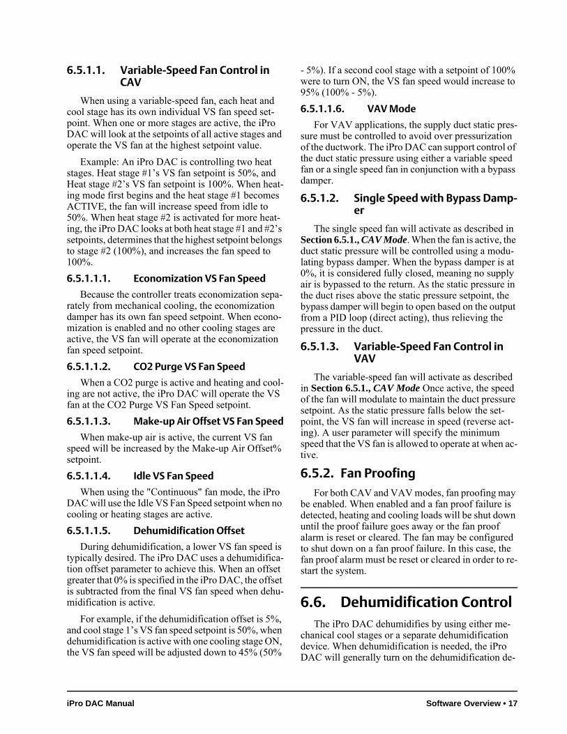
6.4.3.2.2. Secondary Mod Heat
If the modulating heat output is classified as a sec-ondary heating source, it will be activated only after all primary heat stages have staged on, but before any defined secondary heat stages are activated. Once ac-tivated, the modulating heat output will modulate to maintain the supply air temperature at the active sup-ply air heating setpoint. A PID loop will be used to de-termine the capacity output. If the modulating heat output reaches 100% and stays there for the Heat On-Delay period, the first secondary heating stage will be activated. Additional secondary heating stages will be brought on according to the Heat On-Delay as long as the modulating heating output remains at 100%. No additional stages of heating will be activated while the modulating heat output is less than 100%.
Secondary heat stages will be sequentially turned off as demand for heating is reduced. The highest sec-ondary stage will turn off after the modulating heat output has been at minimum capacity for the Heat Off-Delay period. Additional heat stages will be turned off in the same way. Once all secondary heat stages are off, the modulating heat output will remain on until it goes to minimum capacity and stays there for at least the Heat Off-Delay period. After this time,
the modulating heat output will turn off, leaving only the primary heat stages still active. The primary heat stages will then stage off as previously described.
6.4.3.3. Heating OAT Lockout
Heating will only be allowed when the outside air temperature is below the heat lockout temperature setpoint. If the outside temperature rises above this setpoint, heating will be deactivated. Heating will only be re-enabled when the outside temperature falls 2°F below the lockout setpoint.
6.5. Fan ControlThe iPro DAC supports control of either a single
speed fan or a variable speed (VS) indoor fan. The method used to control the fan depends on the appli-cation mode setting (CAV or VAV – see Section 6.1., Application Mode for more information).
6.5.1. CAV ModeThe indoor fan will be controlled in one of three
ways:
• Continuous – The fan is always on, even when the controller is not in heating, cooling, or dehumidifi-cation mode. In variable speed fan control, when heating or cooling is not active, the fan will be ON at a fixed, user-defined idle speed.
• Auto – The fan is only on when the controller is in heating, cooling, dehumidification, or outside air damper operation mode.
• Summer ON, Winter Auto (SOWA) – This mode allows the fan to operate in Continuous mode during the summer months and in Auto mode during the winter months (based on the season passed to the iPro DAC from the E2 controller).
If desired, activation and deactivation delays may be set up for the iPro DAC application for both heat-ing and cooling mode.
Figure 6-2 - Heat Staging Primary Graph
Figure 6-3 - Heat Staging Secondary Graph
16 • Fan Control 026-1727 Rev 0 11-APR-2011
6.5.1.1. Variable-Speed Fan Control in CAV
When using a variable-speed fan, each heat and cool stage has its own individual VS fan speed set-point. When one or more stages are active, the iPro DAC will look at the setpoints of all active stages and operate the VS fan at the highest setpoint value.
Example: An iPro DAC is controlling two heat stages. Heat stage #1’s VS fan setpoint is 50%, and Heat stage #2’s VS fan setpoint is 100%. When heat-ing mode first begins and the heat stage #1 becomes ACTIVE, the fan will increase speed from idle to 50%. When heat stage #2 is activated for more heat-ing, the iPro DAC looks at both heat stage #1 and #2’s setpoints, determines that the highest setpoint belongs to stage #2 (100%), and increases the fan speed to 100%.
6.5.1.1.1. Economization VS Fan Speed
Because the controller treats economization sepa-rately from mechanical cooling, the economization damper has its own fan speed setpoint. When econo-mization is enabled and no other cooling stages are active, the VS fan will operate at the economization fan speed setpoint.
6.5.1.1.2. CO2 Purge VS Fan Speed
When a CO2 purge is active and heating and cool-ing are not active, the iPro DAC will operate the VS fan at the CO2 Purge VS Fan Speed setpoint.
6.5.1.1.3. Make-up Air Offset VS Fan Speed
When make-up air is active, the current VS fan speed will be increased by the Make-up Air Offset% setpoint.
6.5.1.1.4. Idle VS Fan Speed
When using the "Continuous" fan mode, the iPro DAC will use the Idle VS Fan Speed setpoint when no cooling or heating stages are active.
6.5.1.1.5. Dehumidification Offset
During dehumidification, a lower VS fan speed is typically desired. The iPro DAC uses a dehumidifica-tion offset parameter to achieve this. When an offset greater that 0% is specified in the iPro DAC, the offset is subtracted from the final VS fan speed when dehu-midification is active.
For example, if the dehumidification offset is 5%, and cool stage 1’s VS fan speed setpoint is 50%, when dehumidification is active with one cooling stage ON, the VS fan speed will be adjusted down to 45% (50%
- 5%). If a second cool stage with a setpoint of 100% were to turn ON, the VS fan speed would increase to 95% (100% - 5%).
6.5.1.1.6. VAV Mode
For VAV applications, the supply duct static pres-sure must be controlled to avoid over pressurization of the ductwork. The iPro DAC can support control of the duct static pressure using either a variable speed fan or a single speed fan in conjunction with a bypass damper.
6.5.1.2. Single Speed with Bypass Damp-er
The single speed fan will activate as described in Section 6.5.1., CAV Mode. When the fan is active, the duct static pressure will be controlled using a modu-lating bypass damper. When the bypass damper is at 0%, it is considered fully closed, meaning no supply air is bypassed to the return. As the static pressure in the duct rises above the static pressure setpoint, the bypass damper will begin to open based on the output from a PID loop (direct acting), thus relieving the pressure in the duct.
6.5.1.3. Variable-Speed Fan Control in VAV
The variable-speed fan will activate as described in Section 6.5.1., CAV Mode Once active, the speed of the fan will modulate to maintain the duct pressure setpoint. As the static pressure falls below the set-point, the VS fan will increase in speed (reverse act-ing). A user parameter will specify the minimum speed that the VS fan is allowed to operate at when ac-tive.
6.5.2. Fan ProofingFor both CAV and VAV modes, fan proofing may
be enabled. When enabled and a fan proof failure is detected, heating and cooling loads will be shut down until the proof failure goes away or the fan proof alarm is reset or cleared. The fan may be configured to shut down on a fan proof failure. In this case, the fan proof alarm must be reset or cleared in order to re-start the system.
6.6. Dehumidification ControlThe iPro DAC dehumidifies by using either me-
chanical cool stages or a separate dehumidification device. When dehumidification is needed, the iPro DAC will generally turn on the dehumidification de-
iPro DAC Manual Software Overview • 17
vice or activate stages of cooling up to a user-defined maximum number of cool stages to be used for dehu-midification.
A reheat output is also available for units equipped with hot gas reheat. Additionally, the unit’s primary heating outputs may be used to augment or replace the hot gas reheat function.
6.6.1. Enabling DehumidificationThe iPro DAC can use several methods to deter-
mine if the controlled space requires dehumidifica-tion. If the sensor needed for the method selected is not valid, dehumidification will not be available until the sensor operation is corrected or a different method is selected. The methods supported are:
• Dehum by Inside RH
• Dehum by Outside RH
• Dehum by Inside Dewpoint
• Dehum by Outside Dewpoint
6.6.1.1. Dehumidification Setpoint
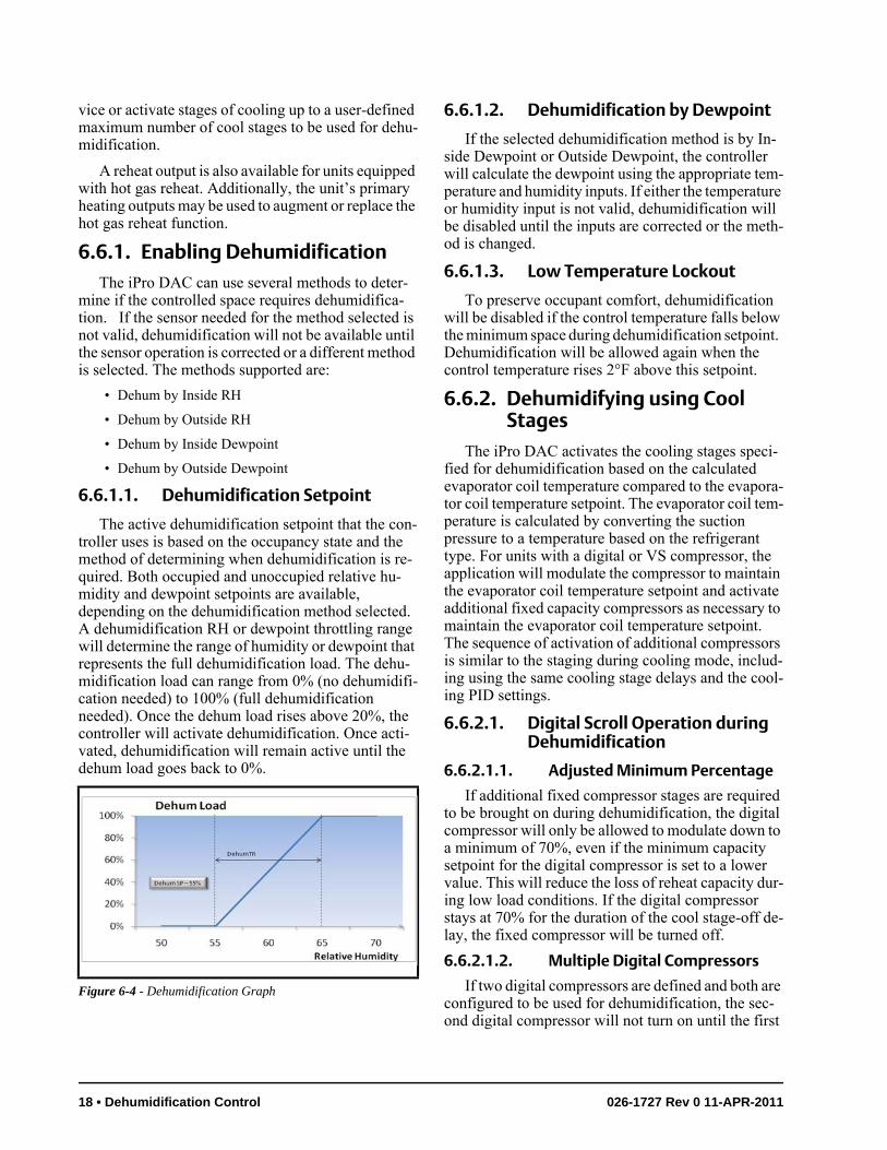
The active dehumidification setpoint that the con-troller uses is based on the occupancy state and the method of determining when dehumidification is re-quired. Both occupied and unoccupied relative hu-midity and dewpoint setpoints are available, depending on the dehumidification method selected. A dehumidification RH or dewpoint throttling range will determine the range of humidity or dewpoint that represents the full dehumidification load. The dehu-midification load can range from 0% (no dehumidifi-cation needed) to 100% (full dehumidification needed). Once the dehum load rises above 20%, the controller will activate dehumidification. Once acti-vated, dehumidification will remain active until the dehum load goes back to 0%.
6.6.1.2. Dehumidification by Dewpoint
If the selected dehumidification method is by In-side Dewpoint or Outside Dewpoint, the controller will calculate the dewpoint using the appropriate tem-perature and humidity inputs. If either the temperature or humidity input is not valid, dehumidification will be disabled until the inputs are corrected or the meth-od is changed.
6.6.1.3. Low Temperature Lockout
To preserve occupant comfort, dehumidification will be disabled if the control temperature falls below the minimum space during dehumidification setpoint. Dehumidification will be allowed again when the control temperature rises 2°F above this setpoint.
6.6.2. Dehumidifying using Cool Stages
The iPro DAC activates the cooling stages speci-fied for dehumidification based on the calculated evaporator coil temperature compared to the evapora-tor coil temperature setpoint. The evaporator coil tem-perature is calculated by converting the suction pressure to a temperature based on the refrigerant type. For units with a digital or VS compressor, the application will modulate the compressor to maintain the evaporator coil temperature setpoint and activate additional fixed capacity compressors as necessary to maintain the evaporator coil temperature setpoint. The sequence of activation of additional compressors is similar to the staging during cooling mode, includ-ing using the same cooling stage delays and the cool-ing PID settings.
6.6.2.1. Digital Scroll Operation during Dehumidification
6.6.2.1.1. Adjusted Minimum Percentage
If additional fixed compressor stages are required to be brought on during dehumidification, the digital compressor will only be allowed to modulate down to a minimum of 70%, even if the minimum capacity setpoint for the digital compressor is set to a lower value. This will reduce the loss of reheat capacity dur-ing low load conditions. If the digital compressor stays at 70% for the duration of the cool stage-off de-lay, the fixed compressor will be turned off.
6.6.2.1.2. Multiple Digital Compressors
If two digital compressors are defined and both are configured to be used for dehumidification, the sec-ond digital compressor will not turn on until the first
Figure 6-4 - Dehumidification Graph
18 • Dehumidification Control 026-1727 Rev 0 11-APR-2011
digital compressor has reached its maximum capaci-ty, similar to how digital compressors stage up in cooling mode. Two suction pressure inputs are sup-ported, so when the second digital compressor is acti-vated, the controller will use the second suction pressure transducer to calculate the coil temperature.
6.6.3. Reheat OutputWhen dehumidification is active, the reheat output
will activate when the supply air temperature drops below the dehumidification supply temperature set-point. However, if a return air bypass damper is con-figured, the reheat output will not be permitted to activate until the return air bypass damper reaches 100%. Once activated, the reheat output will remain active during the remainder of the dehumidification cycle.
6.6.4. Primary Heat Used as ReheatPrimary heating stages can be used instead of or in
addition to the reheat output in order to maintain a de-humidification supply air setpoint. When used in ad-dition to the reheat output, the primary heat will only stage on if the reheat output has been on for the Heat On-Delay period. Primary heat stages will then stage on according to the Heat On-Delay time as long as the supply temperature remains below the dehumidifica-tion supply setpoint. The heat stages will stage off if the supply temperature rises above the dehumidifica-tion supply setpoint plus the dehumidification supply deadband, according to the Heat Off-Delay setpoint.
6.6.5. Return Air Bypass DamperThe return air bypass (RAB) damper is only used
on constant air volume units and only during dehu-midification mode. When defined, the RAB damper acts as the first form of reheat. The RAB damper mod-ulates from 0-100% as the space temperature falls be-low the cooling setpoint. When the space temperature is equal to the cooling setpoint, the RAB damper will be at 0%. When the space temperature falls to halfway between the active cooling and heating setpoints, the RAB damper will be at 100%.
6.6.5.1. Return Air Damper during Dehu-midification
If the unit has a separate actuator for the return air (RA) damper (i.e., not linked to the outdoor air damp-er), the return air damper will proportionally close more as the RAB damper opens during dehumidifica-tion mode. The rate at which the RA damper will close is determined by the RA Damper multiplier set-
point. For example, if the RAB damper is at 50% and the RA damper multiplier is 10%, the RA damper will close an additional 5% from its current position.
6.7. Outside Air ControlThe outside air damper can be used for several
strategies. They are:
• Economization
• Indoor Air Quality (CO2 Control)
• Make-up Air Control
When the outside air damper does not have any functions calling for it to be open, the modulating damper will move to its minimum position and the two-position damper will close. During occupancy, the minimum position will be specified by a user set-point. During unoccupied, the modulating damper will fully close to 0%.
6.7.1. Indoor Air QualityWhen a CO2 sensor input is present on the iPro
DAC or a CO2 value is received from the E2, the out-side air damper may be used to bring fresh air into the building to reduce CO2 levels. The CO2 sensor’s val-ue is compared to the iPro DAC’s CO2 setpoint. If the reading exceeds the setpoint:
• The damper will OPEN and remain open until the CO2 value drops below the setpoint (for two-posi-tion dampers).
• The damper will open and modulate its position based on a PID comparison of the CO2 sensor read-ing and the CO2 setpoint (for variable-position dampers).
6.7.2. Make-up Air ControlWhen an exhaust fan input is present on the iPro
DAC or an exhaust fan active signal is received from the E2, the controller will activate make-up air con-trol. When make-up air is becomes active, the modu-lating damper will open to the make-up air minimum damper position setpoint if it is currently less than that position. If the current modulating damper position is already greater than or equal to the make-up air mini-mum position setpoint, no adjustment to the damper position will occur.
For the two-position damper, when make-up air control is active, the damper will be set open. When make-up air control is inactive, the damper will close.
iPro DAC Manual Software Overview • 19
6.7.3. Economizer ControlEconomizer dampers on rooftop HVAC units are
used to bring outside air into the building for use in cooling. The iPro DAC supports control of two-posi-tion outside air dampers as well as variable-position (analog) dampers.
The iPro DAC controls economization by first de-termining whether the outside air conditions are fa-vorable for bringing in outside air (see Section 6.7.3.3., Economization Enabling Strategy). If the air is not favorable for economization, the iPro DAC will close the dampers. If the air is favorable for econ-omization, the iPro DAC will use the dampers like a preliminary stage of cooling, opening them first when cooling is first called for, and then activating more cool stages only if necessary to maintain the setpoint.
6.7.3.1. Operation of Two-Position Dampers During Economization
Two-position dampers are set to the OPEN posi-tion when economization is enabled and the space temperature is above the space economization set-point. The damper will remain OPEN until cooling is not required, or until the iPro DAC determines the outside air is not favorable for economization, at which time the dampers will be set to the CLOSED position.
6.7.3.2. Operation of Variable-Position Dampers During Economization
When economization is enabled and the space temperature is above the space economization set-point, the iPro DAC controls the position of the damp-er using a PID algorithm, using a mixed air temperature sensor (mounted where the sensor may measure the mixture of outside air and return air) and a mixed air temp setpoint.
The iPro DAC opens and closes the damper incre-mentally to attempt to maintain the mixed air temp setpoint. The iPro DAC will close the damper when the mixed air is below the setpoint to keep cooler air from entering, and open the damper when the mixed air is above setpoint and requires cooler air from out-side.
If the space temperature becomes too cold, or the iPro DAC determines outside air conditions are not favorable for economization, the iPro DAC will close the damper to a user-defined minimum damper posi-tion.
6.7.3.3. Economization Enabling Strate-gy
When communicating with the E2, the iPro DAC only allows economization if it receives an economiz-er enable signal from the E2. It does not use other strategies to enable the economizer. However, in standalone mode, the iPro DAC has multiple user se-lectable strategies available for determining whether outside air conditions are favorable for economiza-tion. Each method of economization checking has a failsafe in case one of the sensors required for the strategy becomes unavailable.
1. Dewpoint Setpoint – When selected, this method requires an outside temperature and humidity sensor to be connected to the con-troller. Using these sensors, an outside dew-point value is calculated. When the outside dewpoint is less than the dewpoint setpoint, economization will be enabled. If the outside humidity sensor fails, the controller will re-vert to the Dry Bulb Compare method. If the outside temperature sensor fails, economiza-tion will be disabled.
2. Enthalpy Comparison – When selected, this method requires an inside and outside humid-ity sensor as well as an outside temperature sensor to be connected to the controller. Us-ing these sensors, both inside and outside en-thalpy values are calculated. When outside enthalpy is less than inside enthalpy, econo-mization will be enabled. If the outside hu-midity sensor fails, the application will revert to the Dry Bulb Compare method. If an inside temperature or humidity sensor fails, the ap-plication will revert to using the Enthalpy Setpoint method. If the outside temperature sensor fails, economization will be disabled.
3. Enthalpy Setpoint – When selected, this method requires an outside humidity and temperature sensor to be connected to the controller. Using these sensors, an outside enthalpy is calculated. When the outside en-thalpy is less than the enthalpy setpoint, econ-omization will be enabled. If the outside humidity sensor fails, the application will re-vert to the Dry Bulb Compare method. If the outside temperature sensor fails, economiza-tion will be disabled.
4. Dry Bulb Compare – When selected, this method requires an outside temperature sen-sor to be connected to the controller. When the outside temperature is less than the inside temperature by at least 2°F, economization will be enabled. If the outside temperature
20 • Outside Air Control 026-1727 Rev 0 11-APR-2011
sensor fails, economization will be disabled.
5. E2 Zone Enable (BAS) – This method is al-ways used when the iPro DAC is connected to the E2. The controller will read the value of the ECONOMIZATION output from the E2 zone and enable economization based on that value. The E2 zone must be programmed with its own method of economization check-ing (refer to the E2 user manual 026-1610 and on-line help for HVAC Zone application set-up instructions).
6.7.4. Smoke DetectionThe iPro DAC may be programmed with a Smoke
Detector input, which accepts a dry-contact digital signal from a smoke alarm or a building control net-work. When the smoke detector contact closes to in-dicate smoke has been detected, the controller will enter the Emergency Shutdown mode and all of the iPro DAC’s heating/cooling and fans will be overrid-den OFF and the outside air damper will be closed.
6.7.5. Priority When Economization, CO2 Control, and Make-up Air are Used Together
When Economization, CO2 and Make-up Air con-trol are used together in the same iPro DAC, it will control a two-position damper using OR logic (OPEN if one or more strategies require it to be open, CLOSED if none do not require it to be open).
Variable-position dampers will be controlled based on which control calls for the highest percent-age. In other words, if the damper needs to be set to 60% to satisfy CO2 fresh air requirements and 40% to satisfy the economization mixed air temperature set-point, the damper will be opened to 60%.
6.7.6. Return Damper ControlAn optional modulating return air damper may be
connected to the iPro DAC. When connected, the re-turn air damper will modulate inversely proportional to the outside air damper. For example, if the outside air damper is at 10%, the return air damper will be at 90%. If the outside air damper goes to 100%, the re-turn air damper will go to 0%.
During dehumidification, and if a return air bypass damper connected to the iPro DAC, the return air damper may deviate from its standard calculated po-sition to assist in the dehumidification process. See Section 6.5.1.1., Variable-Speed Fan Control in CAV for more details.
6.8. 6.10 Reversing Valve Con-trol
The iPro DAC supports control of a heat or cool reversing valve. The type of reversing valve can be selected by the user. The valve may be connected to any relay output on an iPro DAC designated as a re-versing valve. If the valve is defined as a heating re-versing valve, the relay will energize when heat is active, and will de-energize when cool is active. The valve will stay in its current position when the unit goes to idle mode. Likewise, if the valve is defined as a cooling reversing valve, the relay will energize only when cool is active, and will de-energize when heat is active.
6.9. Standalone FunctionalityIf for some reason an iPro DAC board loses com-
munications with its parent E2 unit for longer than two minutes, the board will go into Standalone mode.
In Standalone mode, the iPro DAC will continue Temperature Control as normal using the space tem-perature and supply temperature as a control inputs. The iPro DAC does not have an internal schedule and will therefore revert to occupied mode while operat-ing standalone mode.
Dehumidification and Economization will occur during stand-alone mode only if the board is equipped with the right local sensors for the strategies selected.
Any control features that rely on communication with the E2 will not be available. This includes:
• Demand Shed
• Setpoint Reset
• Optimum Start/Stop
• Summer/Winter Setpoints
• Overrides Initiated by E2
6.10. Control Temperature Sen-sor Failures
In many cases, the iPro DAC can compensate for sensor failures by substituting other sensor values. This allows the iPro DAC to continue operating as close to normal as possible until the failed sensors can be fixed or replaced. However, it is important to note
iPro DAC Manual Software Overview • 21
that if the supply temperature sensor fails, the unit will not be able to turn on any heating or cooling stag-es. This sensor must be repaired immediately.
Control Temp Failure
The preferred sensor to be used to control the space is user configured. By default, Space Temp 1 is the sensor used. However, Space Temp 2, the average of both Space Temps, Return Temp, calculated Ap-parent Temp or a Zone Temperature from the E2 can be selected as the primary control temperature.
If the preferred sensor fails, a backup sensor will be selected based on a user configured fallback sensor selection. If this sensor also fails, the iPro DAC will use the following priority for selecting a control tem-perature:
1. Space Temp 1
2. Space Temp 2
3. Return Temp
4. Zone Temp (sent from E2)
If no valid control temperature is available, a fail-ure alarm will be generated and sent to the E2 Alarm Advisory Log.
Outside Air Temp Failure
Failure of the outside air temperature sensor af-fects Economization only if the iPro DAC is in stand-alone mode. In this case, the iPro DAC will disable the economization strategy until the outside air tem-perature sensor is repaired.
Mixed Air Temperature Failure
If the iPro DAC has a modulating outdoor air damper defined, it will use the mixed air temperature sensor as its control input for economization (free-cooling). If the mixed air temperature sensor fails, it will substitute the supply air temperature sensor as its control value and continue economization. If neither the mixed air temperature or supply air temperature sensors are available, economization will be locked OFF and the damper will be closed until the sensor failures can be addressed.
Inside Humidity Failure
The iPro DAC will use the local indoor humidity sensor if it is defined. If no local indoor humidity sen-sor is defined, the iPro DAC will use the indoor hu-midity value received from the E2. If no valid value is received from the E2, the dehumidification function will be disabled until a valid indoor humidity reading
is detected. This applies only if the dehumidification strategy is configured to use inside humidity or inside dewpoint. Also, when in standalone mode, if no valid inside humidity is detected, the Enthalpy Compare economization strategy, if selected, will be disabled and the controller will revert to using the Enthalpy Setpoint method of economization.
Outside Humidity Failure
The iPro DAC will use the local outdoor humidity sensor if it is defined. If no local outdoor humidity sensor is defined, the iPro DAC will use the outdoor humidity value received from the E2. If no valid value is received from the E2, the dehumidification function will be disabled until a valid outdoor humidity read-ing is detected. This applies only if the dehumidifica-tion strategy is configured to use outdoor humidity or outdoor dewpoint. Also, when in standalone mode, if no valid outdoor humidity is detected, the economiza-tion method will revert to Dry Bulb Compare.
22 • Control Temperature Sensor Failures 026-1727 Rev 0 11-APR-2011

7 E2 Setup
The iPro DAC is capable of communicating with an E2 version 3.0 or above.
Using iPro DAC with a central E2 offers several benefits over simple standalone control, including:
• Reporting of iPro DAC-related alarms in the Alarm Advisory Log.
• The ability to log iPro DAC inputs in an E2 logging group.
• The ability to share outside air temperature values and control motor room temperature by sharing in-put values between the iPro and the E2.
• Remote access to iPro DAC status and programming from the E2 front panel.
• The ability to remotely access the iPro DAC from UltraSite32 or Site Manager, and to back up, restore, and offline-program iPro DAC configuration along with E2 site configuration.
Communication between E2 and an iPro DAC takes place over the RS485 MODBUS. Follow the in-structions in Section 3, The MODBUS Network, to connect an iPro DAC to the E2 MODBUS network. Then, follow the instructions in this chapter to set up the iPro DAC.
7.1. Network Connection to E2
Connecting a iPro DAC to an E2 unit requires the E2 to be version 3.0 or above. Contact Retail Solu-tions for upgrade information if the controller is a ver-sion prior to 3.0.
An E2 has up to three COM ports that can be as-signed for MODBUS communication (COM2, an RS485 port on the E2 power interface board, and COM4 and COM6, which are optional ports requiring expansion cards). COM ports can only be used for one function; in other words, if COM2 is set up as the MODBUS, you cannot connect MODBUS devices to COM2. Ensure your E2 is equipped with an RS485 COM Card (P/N 637-4890) and configured in E2 General Services (, Serial tab) to en-able COM4 or an E2 Expansion COM Card (P/N 637-4871) to enable COM6.
Connect the MODBUS network cable to the three-terminal connector on the COM port you wish to as-sign as MODBUS. Like other iPro DAC connections, wire RS485+ to RS485+, RS485- to RS485-, and the shield cable to the middle terminal. If the E2 will be the first device in the daisy-chain, set the port’s termi-
Figure 7-1 - Location of E2 COM Ports (E2 Versions 3.xx and Below)
E2 PIB COM PORT ASSOCIATIONS
COM1
COM4
COM6
COM2
Serial DeviceRS485 COM Port (2 Connectors)
RS485 COM Card (2 Connectors) Serial Device
RS232 Port
POWER INTERFACE BOARD (PIB)
E2 Modem/Expansion COM Card MountedAbove PIB
Plug-In ModemCard
COM3
E2 Enclosure (Right Side)
RS485
RS232
iPro DAC Manual E2 Setup • 23
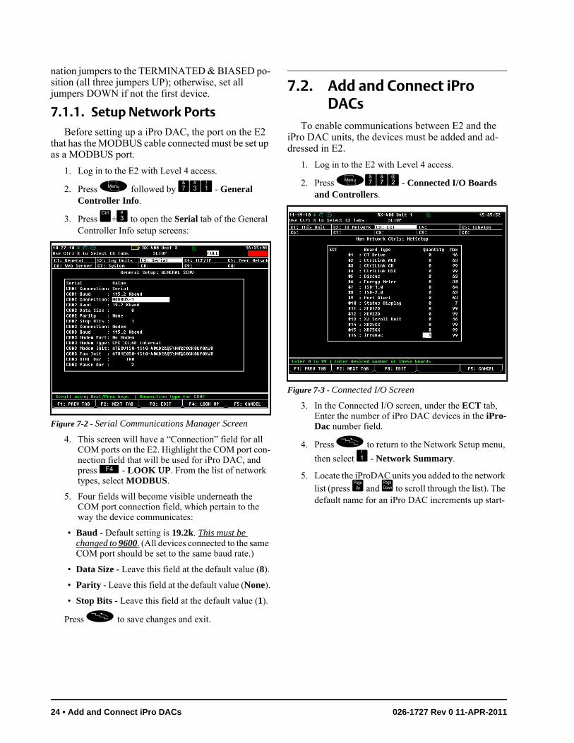
nation jumpers to the TERMINATED & BIASED po-sition (all three jumpers UP); otherwise, set all jumpers DOWN if not the first device.
7.1.1. Setup Network PortsBefore setting up a iPro DAC, the port on the E2
that has the MODBUS cable connected must be set up as a MODBUS port.
1. Log in to the E2 with Level 4 access.
2. Press followed by - General Controller Info.
3. Press + to open the Serial tab of the General Controller Info setup screens:
4. This screen will have a “Connection” field for all COM ports on the E2. Highlight the COM port con-nection field that will be used for iPro DAC, and press - LOOK UP. From the list of network types, select MODBUS.
5. Four fields will become visible underneath the COM port connection field, which pertain to the way the device communicates:
• Baud - Default setting is 19.2k. This must be changed to 9600. (All devices connected to the same COM port should be set to the same baud rate.)
• Data Size - Leave this field at the default value (8).
• Parity - Leave this field at the default value (None).
• Stop Bits - Leave this field at the default value (1).
Press to save changes and exit.
7.2. Add and Connect iPro DACs
To enable communications between E2 and the iPro DAC units, the devices must be added and ad-dressed in E2.
1. Log in to the E2 with Level 4 access.
2. Press - Connected I/O Boards and Controllers.
3. In the Connected I/O screen, under the ECT tab, Enter the number of iPro DAC devices in the iPro-Dac number field.
4. Press to return to the Network Setup menu,
then select - Network Summary.
5. Locate the iProDAC units you added to the network list (press and to scroll through the list). The default name for an iPro DAC increments up start-
Figure 7-2 - Serial Communications Manager Screen
Figure 7-3 - Connected I/O Screen
24 • Add and Connect iPro DACs 026-1727 Rev 0 11-APR-2011
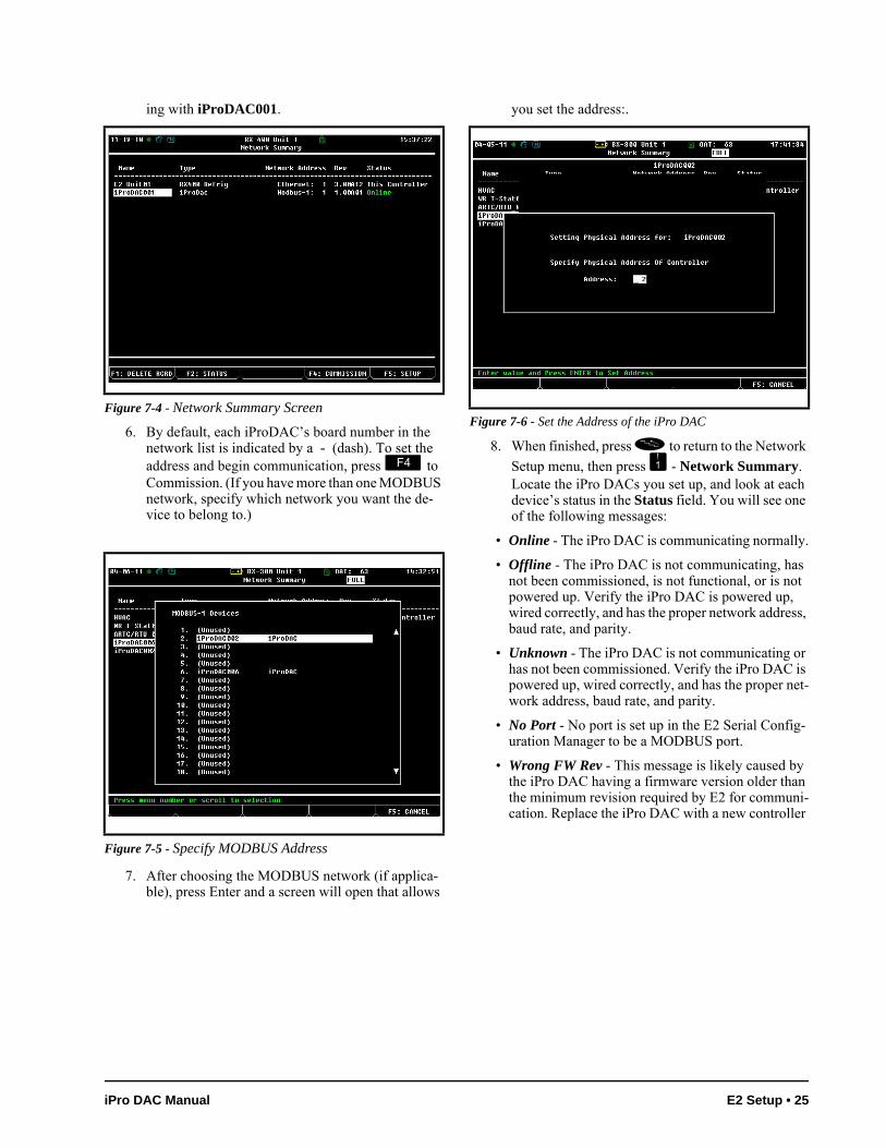
ing with iProDAC001.
6. By default, each iProDAC’s board number in the network list is indicated by a - (dash). To set the address and begin communication, press to Commission. (If you have more than one MODBUS network, specify which network you want the de-vice to belong to.)
7. After choosing the MODBUS network (if applica-ble), press Enter and a screen will open that allows
you set the address:.
8. When finished, press to return to the Network
Setup menu, then press - Network Summary. Locate the iPro DACs you set up, and look at each device’s status in the Status field. You will see one of the following messages:
• Online - The iPro DAC is communicating normally.
• Offline - The iPro DAC is not communicating, has not been commissioned, is not functional, or is not powered up. Verify the iPro DAC is powered up, wired correctly, and has the proper network address, baud rate, and parity.
• Unknown - The iPro DAC is not communicating or has not been commissioned. Verify the iPro DAC is powered up, wired correctly, and has the proper net-work address, baud rate, and parity.
• No Port - No port is set up in the E2 Serial Config-uration Manager to be a MODBUS port.
• Wrong FW Rev - This message is likely caused by the iPro DAC having a firmware version older than the minimum revision required by E2 for communi-cation. Replace the iPro DAC with a new controller
Figure 7-4 - Network Summary Screen
Figure 7-5 - Specify MODBUS Address
Figure 7-6 - Set the Address of the iPro DAC
iPro DAC Manual E2 Setup • 25
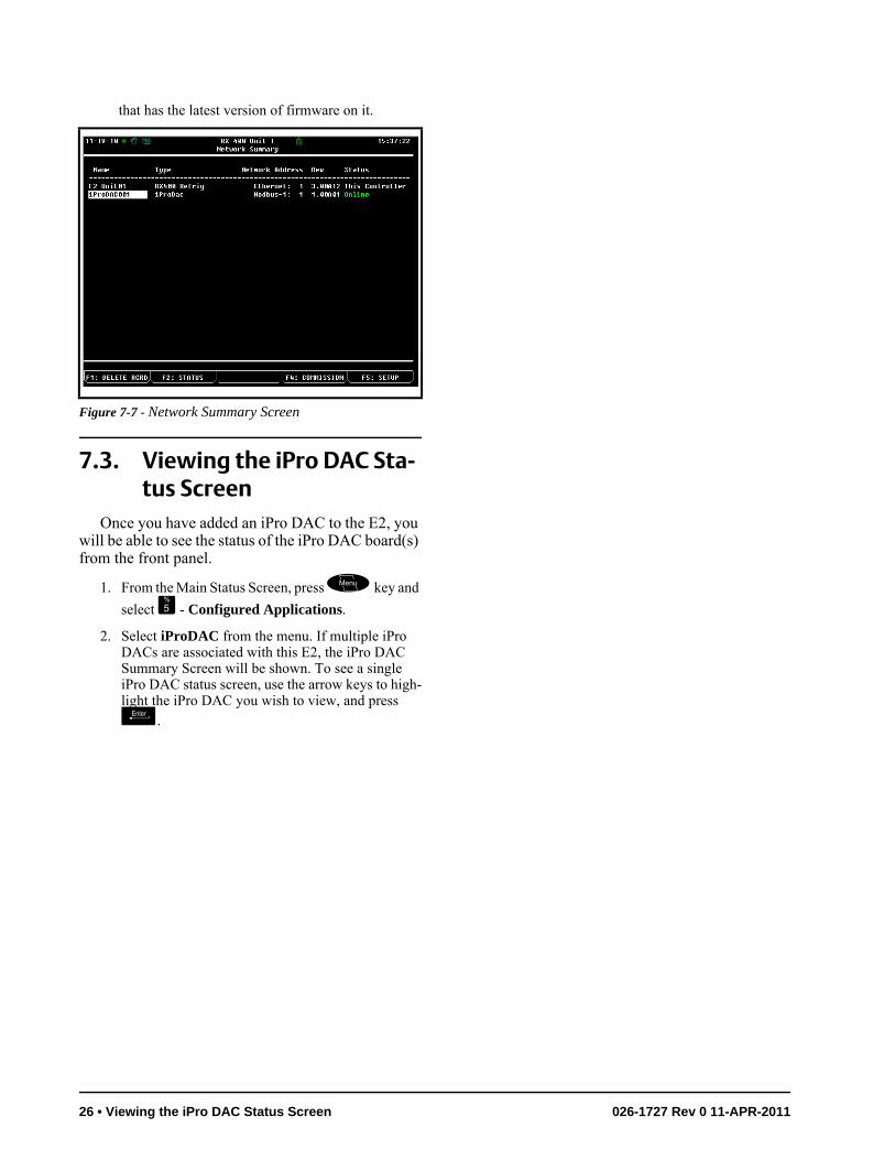
that has the latest version of firmware on it.
7.3. Viewing the iPro DAC Sta-tus Screen
Once you have added an iPro DAC to the E2, you will be able to see the status of the iPro DAC board(s) from the front panel.
1. From the Main Status Screen, press key and
select - Configured Applications.
2. Select iProDAC from the menu. If multiple iPro DACs are associated with this E2, the iPro DAC Summary Screen will be shown. To see a single iPro DAC status screen, use the arrow keys to high-light the iPro DAC you wish to view, and press .
Figure 7-7 - Network Summary Screen
26 • Viewing the iPro DAC Status Screen 026-1727 Rev 0 11-APR-2011
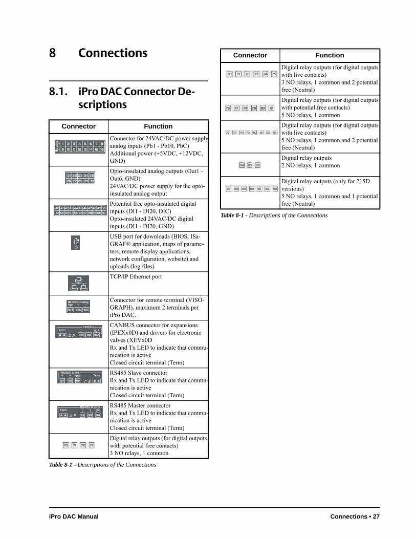
8 Connections
8.1. iPro DAC Connector De-scriptions
Connector Function
Connector for 24VAC/DC power supplyanalog inputs (Pb1 - Pb10, PbC)Additional power (+5VDC, +12VDC, GND)
Opto-insulated analog outputs (Out1 - Out6, GND)24VAC/DC power supply for the opto-insulated analog output
Potential free opto-insulated digital inputs (DI1 - DI20, DIC)Opto-insulated 24VAC/DC digital inputs (DI1 - DI20, GND)
USB port for downloads (BIOS, ISa-GRAF® application, maps of parame-ters, remote display applications, network configuration, website) and uploads (log files)
TCP/IP Ethernet port
Connector for remote terminal (VISO-GRAPH), maximum 2 terminals per iPro DAC.
CANBUS connector for expansions (IPEXx0D) and drivers for electronic valves (XEVx0DRx and Tx LED to indicate that commu-nication is activeClosed circuit terminal (Term)
RS485 Slave connectorRx and Tx LED to indicate that commu-nication is activeClosed circuit terminal (Term)
RS485 Master connectorRx and Tx LED to indicate that commu-nication is activeClosed circuit terminal (Term)
Digital relay outputs (for digital outputs with potential free contacts)3 NO relays, 1 common
Table 8-1 - Descriptions of the Connections
Digital relay outputs (for digital outputs with live contacts)3 NO relays, 1 common and 2 potential free (Neutral)
Digital relay outputs (for digital outputs with potential free contacts)5 NO relays, 1 common
Digital relay outputs (for digital outputs with live contacts)5 NO relays, 1 common and 2 potential free (Neutral)
Digital relay outputs2 NO relays, 1 common
Digital relay outputs (only for 215D versions)5 NO relays, 1 common and 1 potential free (Neutral)
Connector Function
Table 8-1 - Descriptions of the Connections
iPro DAC Manual Connections • 27
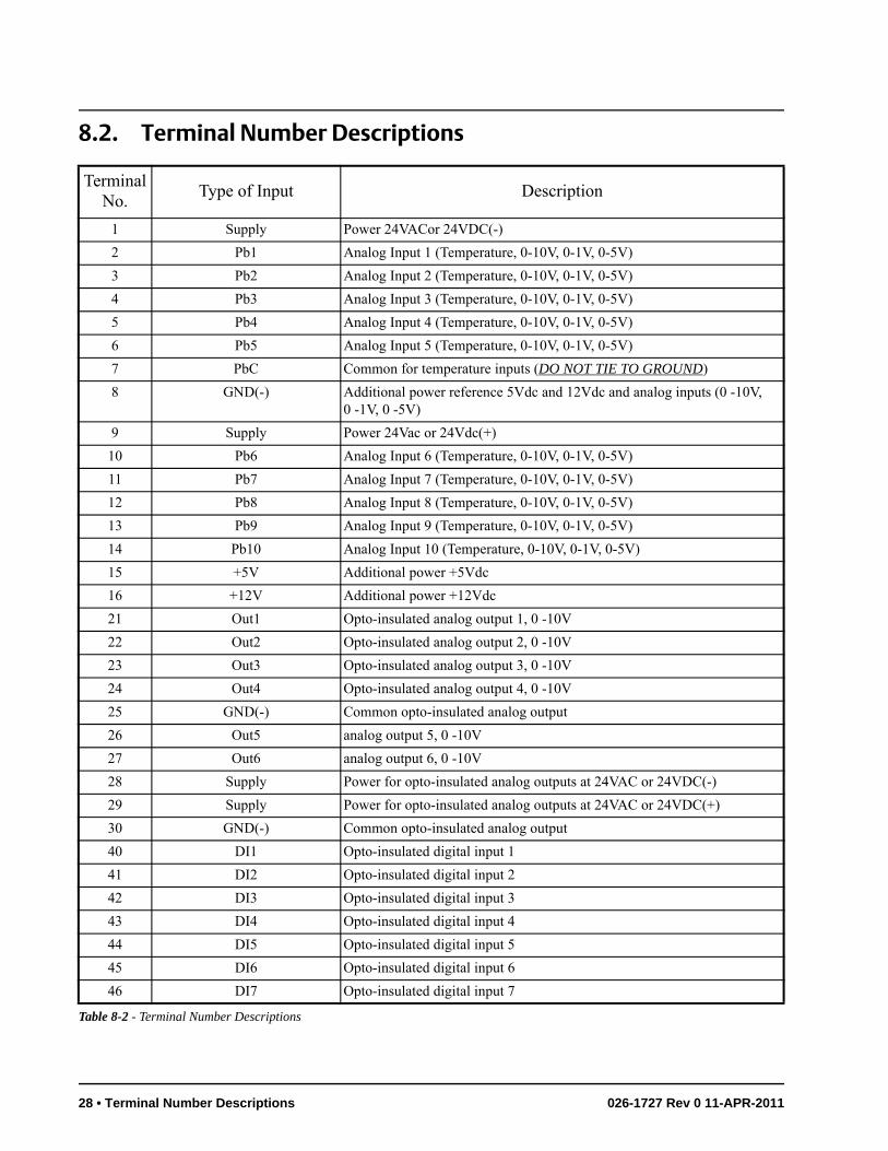
8.2. Terminal Number Descriptions
Terminal No.
Type of Input Description
1 Supply Power 24VACor 24VDC(-)
2 Pb1 Analog Input 1 (Temperature, 0-10V, 0-1V, 0-5V)
3 Pb2 Analog Input 2 (Temperature, 0-10V, 0-1V, 0-5V)
4 Pb3 Analog Input 3 (Temperature, 0-10V, 0-1V, 0-5V)
5 Pb4 Analog Input 4 (Temperature, 0-10V, 0-1V, 0-5V)
6 Pb5 Analog Input 5 (Temperature, 0-10V, 0-1V, 0-5V)
7 PbC Common for temperature inputs (DO NOT TIE TO GROUND)
8 GND(-) Additional power reference 5Vdc and 12Vdc and analog inputs (0 -10V, 0 -1V, 0 -5V)
9 Supply Power 24Vac or 24Vdc(+)
10 Pb6 Analog Input 6 (Temperature, 0-10V, 0-1V, 0-5V)
11 Pb7 Analog Input 7 (Temperature, 0-10V, 0-1V, 0-5V)
12 Pb8 Analog Input 8 (Temperature, 0-10V, 0-1V, 0-5V)
13 Pb9 Analog Input 9 (Temperature, 0-10V, 0-1V, 0-5V)
14 Pb10 Analog Input 10 (Temperature, 0-10V, 0-1V, 0-5V)
15 +5V Additional power +5Vdc
16 +12V Additional power +12Vdc
21 Out1 Opto-insulated analog output 1, 0 -10V
22 Out2 Opto-insulated analog output 2, 0 -10V
23 Out3 Opto-insulated analog output 3, 0 -10V
24 Out4 Opto-insulated analog output 4, 0 -10V
25 GND(-) Common opto-insulated analog output
26 Out5 analog output 5, 0 -10V
27 Out6 analog output 6, 0 -10V
28 Supply Power for opto-insulated analog outputs at 24VAC or 24VDC(-)
29 Supply Power for opto-insulated analog outputs at 24VAC or 24VDC(+)
30 GND(-) Common opto-insulated analog output
40 DI1 Opto-insulated digital input 1
41 DI2 Opto-insulated digital input 2
42 DI3 Opto-insulated digital input 3
43 DI4 Opto-insulated digital input 4
44 DI5 Opto-insulated digital input 5
45 DI6 Opto-insulated digital input 6
46 DI7 Opto-insulated digital input 7
Table 8-2 - Terminal Number Descriptions
28 • Terminal Number Descriptions 026-1727 Rev 0 11-APR-2011
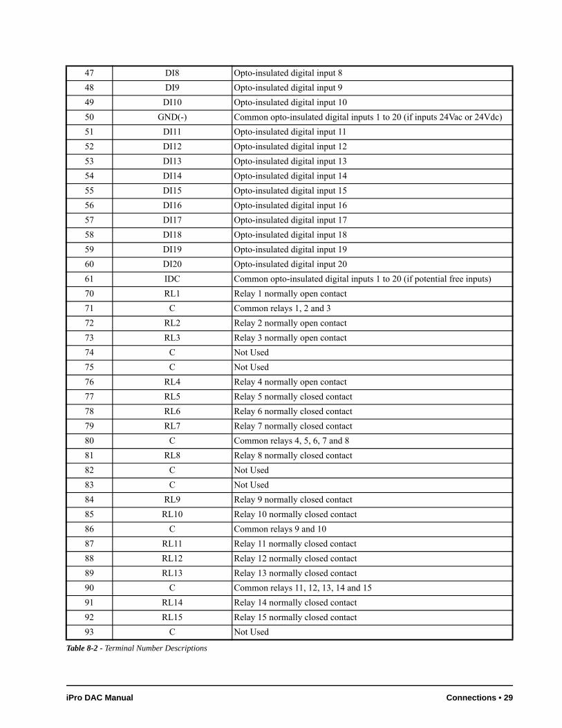
47 DI8 Opto-insulated digital input 8
48 DI9 Opto-insulated digital input 9
49 DI10 Opto-insulated digital input 10
50 GND(-) Common opto-insulated digital inputs 1 to 20 (if inputs 24Vac or 24Vdc)
51 DI11 Opto-insulated digital input 11
52 DI12 Opto-insulated digital input 12
53 DI13 Opto-insulated digital input 13
54 DI14 Opto-insulated digital input 14
55 DI15 Opto-insulated digital input 15
56 DI16 Opto-insulated digital input 16
57 DI17 Opto-insulated digital input 17
58 DI18 Opto-insulated digital input 18
59 DI19 Opto-insulated digital input 19
60 DI20 Opto-insulated digital input 20
61 IDC Common opto-insulated digital inputs 1 to 20 (if potential free inputs)
70 RL1 Relay 1 normally open contact
71 C Common relays 1, 2 and 3
72 RL2 Relay 2 normally open contact
73 RL3 Relay 3 normally open contact
74 C Not Used
75 C Not Used
76 RL4 Relay 4 normally open contact
77 RL5 Relay 5 normally closed contact
78 RL6 Relay 6 normally closed contact
79 RL7 Relay 7 normally closed contact
80 C Common relays 4, 5, 6, 7 and 8
81 RL8 Relay 8 normally closed contact
82 C Not Used
83 C Not Used
84 RL9 Relay 9 normally closed contact
85 RL10 Relay 10 normally closed contact
86 C Common relays 9 and 10
87 RL11 Relay 11 normally closed contact
88 RL12 Relay 12 normally closed contact
89 RL13 Relay 13 normally closed contact
90 C Common relays 11, 12, 13, 14 and 15
91 RL14 Relay 14 normally closed contact
92 RL15 Relay 15 normally closed contact
93 C Not Used
Table 8-2 - Terminal Number Descriptions
iPro DAC Manual Connections • 29
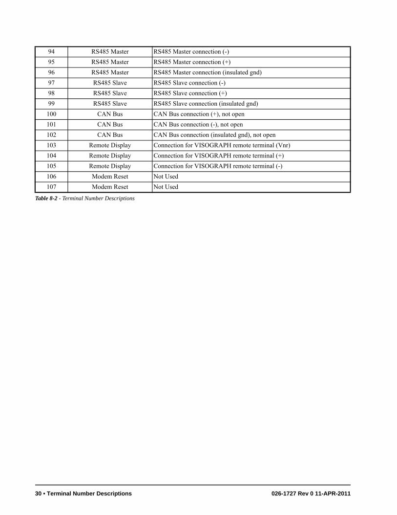
94 RS485 Master RS485 Master connection (-)
95 RS485 Master RS485 Master connection (+)
96 RS485 Master RS485 Master connection (insulated gnd)
97 RS485 Slave RS485 Slave connection (-)
98 RS485 Slave RS485 Slave connection (+)
99 RS485 Slave RS485 Slave connection (insulated gnd)
100 CAN Bus CAN Bus connection (+), not open
101 CAN Bus CAN Bus connection (-), not open
102 CAN Bus CAN Bus connection (insulated gnd), not open
103 Remote Display Connection for VISOGRAPH remote terminal (Vnr)
104 Remote Display Connection for VISOGRAPH remote terminal (+)
105 Remote Display Connection for VISOGRAPH remote terminal (-)
106 Modem Reset Not Used
107 Modem Reset Not Used
Table 8-2 - Terminal Number Descriptions
30 • Terminal Number Descriptions 026-1727 Rev 0 11-APR-2011
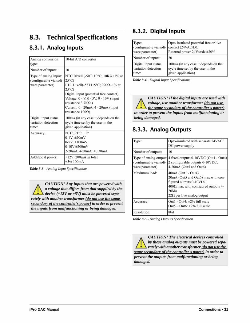
8.3. Technical Specifications
8.3.1. Analog Inputs
8.3.2. Digital Inputs
8.3.3. Analog Outputs
Analog conversion type:
10-bit A/D converter
Number of inputs: 10
Type of analog input:(configurable via soft-ware parameter)
NTC Dixell (-50T110°C; 10KΩ±1% at 25°C)PTC Dixell(-55T115°C; 990Ω±1% at 25°C)Digital input (potential free contact)Voltage: 0 - V, 0 - 5V, 0 - 10V (input resistance 3.7KΩ )Current: 0 - 20mA, 4 - 20mA (input resistance 100Ω)
Digital input status variation detection time:
100ms (in any case it depends on the cycle time set by the user in thegiven application)
Accuracy: NTC, PTC: ±1?0-1V: ±20mV0-5V: ±100mV0-10V:±200mV2-20mA, 4-20mA: ±0.30mA
Additional power: +12V: 200mA in total+5v: 100mA
Table 8-3 - Analog Input Specifications
CAUTION! Any inputs that are powered with a voltage that differs from that supplied by the device (+12V or +5V) must be powered sepa-
rately with another transformer (do not use the same secondary of the controller's power) in order to prevent the inputs from malfunctioning or being damaged.
Type:(configurable via soft-ware parameter)
Opto-insulated potential free or live contact (24VAC/DC)External power 24Vac/dc ±20%
Number of inputs: 20
Digital input status variation detection time:
100ms (in any case it depends on the cycle time set by the user in thegiven application)
Table 8-4 - Digital Input Specifications
CAUTION! If the digital inputs are used with voltage, use another transformer (do not use the same secondary of the controller's power)
in order to prevent the inputs from malfunctioning or being damaged.
Type: Opto-insulated with separate 24VAC/DC power supply
Number of outputs: 10
Type of analog output:(configurable via soft-ware parameter)
4 fixed outputs 0-10VDC (Out1 - Out4)2 configurable outputs 0-10VDC, 4-20mA (Out5 and Out6)
Maximum load: 40mA (Out1 - Out4)20mA (Out5 and Out6) max with con-figured outputs 0-10VDC400Ω max with configured outputs 4-20Ma22Ω per live analog output
Accuracy: Out1 - Out4: ±2% full scaleOut5 – Out6: ±2% full scale
Resolution: 8bit
Table 8-5 - Analog Outputs Specification
CAUTION! The electrical devices controlled by these analog outputs must be powered sepa-rately with another transformer (do not use the
same secondary of the controller's power) in order to prevent the outputs from malfunctioning or being damaged.
iPro DAC Manual Connections • 31
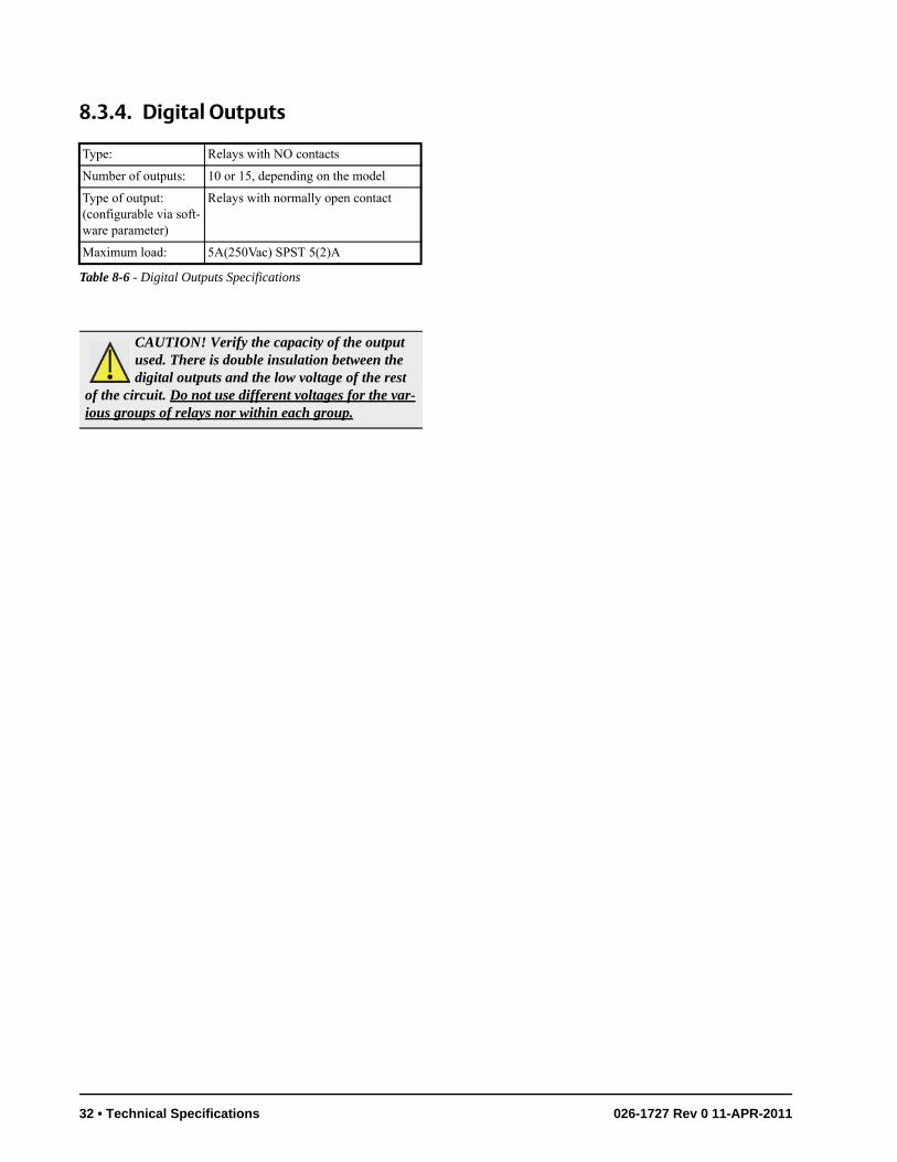
8.3.4. Digital Outputs
Type: Relays with NO contacts
Number of outputs: 10 or 15, depending on the model
Type of output:(configurable via soft-ware parameter)
Relays with normally open contact
Maximum load: 5A(250Vac) SPST 5(2)A
Table 8-6 - Digital Outputs Specifications
CAUTION! Verify the capacity of the output used. There is double insulation between the digital outputs and the low voltage of the rest
of the circuit. Do not use different voltages for the var-ious groups of relays nor within each group.
32 • Technical Specifications 026-1727 Rev 0 11-APR-2011
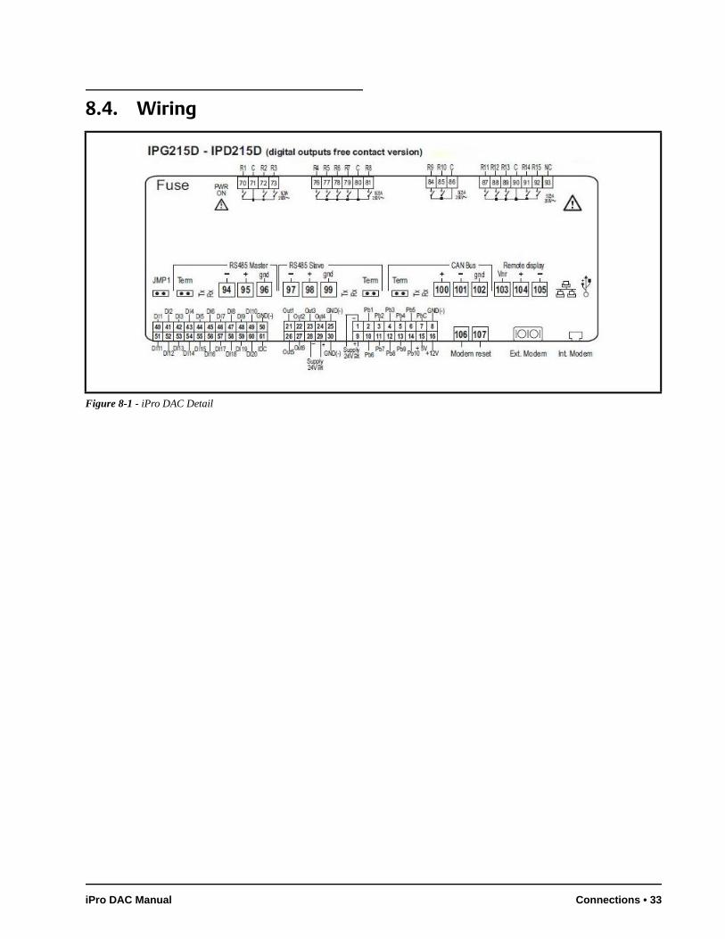
8.4. Wiring
Figure 8-1 - iPro DAC Detail
iPro DAC Manual Connections • 33
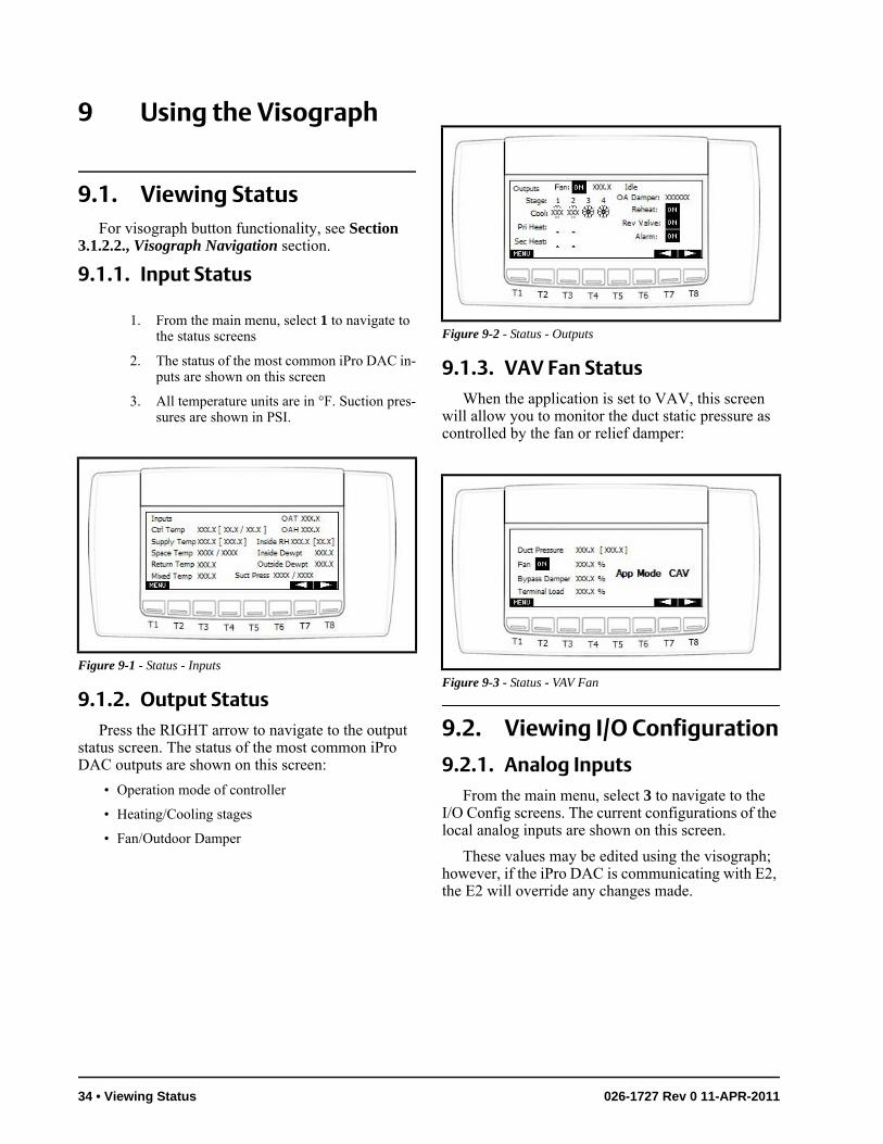
9 Using the Visograph
9.1. Viewing StatusFor visograph button functionality, see Section
3.1.2.2., Visograph Navigation section.
9.1.1. Input Status
1. From the main menu, select 1 to navigate to the status screens
2. The status of the most common iPro DAC in-puts are shown on this screen
3. All temperature units are in °F. Suction pres-sures are shown in PSI.
9.1.2. Output StatusPress the RIGHT arrow to navigate to the output
status screen. The status of the most common iPro DAC outputs are shown on this screen:
• Operation mode of controller
• Heating/Cooling stages
• Fan/Outdoor Damper
9.1.3. VAV Fan StatusWhen the application is set to VAV, this screen
will allow you to monitor the duct static pressure as controlled by the fan or relief damper:
9.2. Viewing I/O Configuration
9.2.1. Analog InputsFrom the main menu, select 3 to navigate to the
I/O Config screens. The current configurations of the local analog inputs are shown on this screen.
These values may be edited using the visograph; however, if the iPro DAC is communicating with E2, the E2 will override any changes made.
Figure 9-1 - Status - Inputs
Figure 9-2 - Status - Outputs
Figure 9-3 - Status - VAV Fan
34 • Viewing Status 026-1727 Rev 0 11-APR-2011
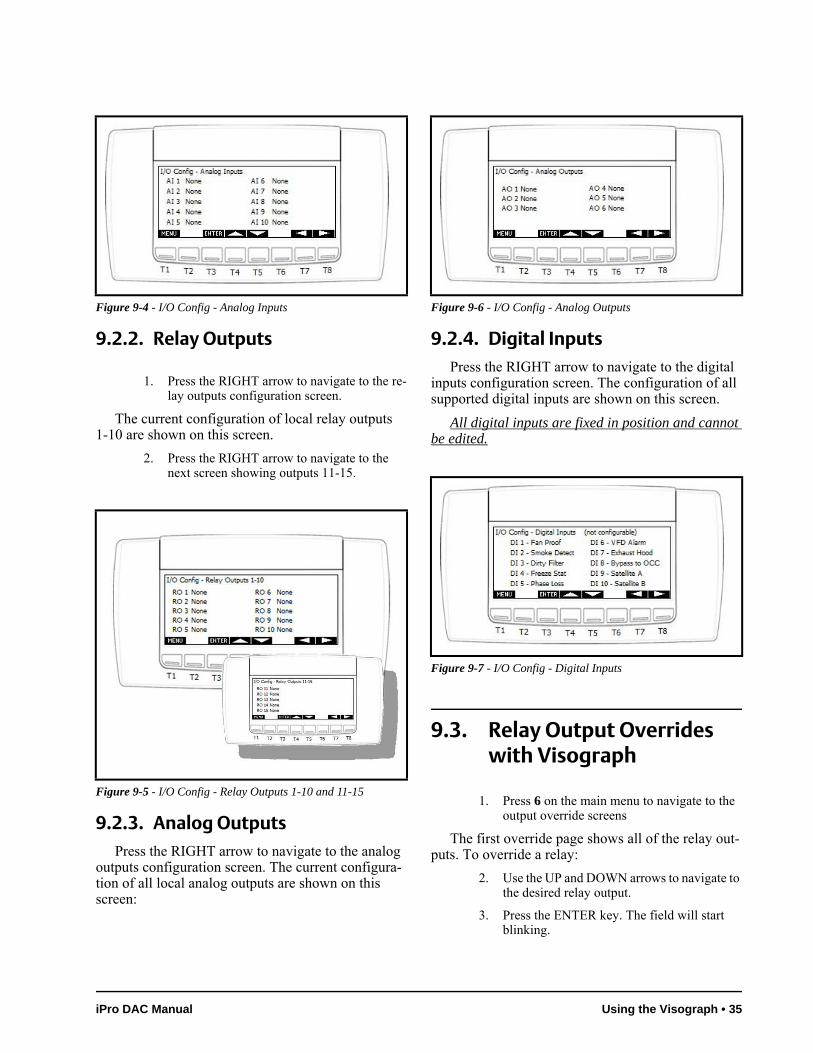
9.2.2. Relay Outputs
1. Press the RIGHT arrow to navigate to the re-lay outputs configuration screen.
The current configuration of local relay outputs 1-10 are shown on this screen.
2. Press the RIGHT arrow to navigate to the next screen showing outputs 11-15.
9.2.3. Analog OutputsPress the RIGHT arrow to navigate to the analog
outputs configuration screen. The current configura-tion of all local analog outputs are shown on this screen:
9.2.4. Digital InputsPress the RIGHT arrow to navigate to the digital
inputs configuration screen. The configuration of all supported digital inputs are shown on this screen.
All digital inputs are fixed in position and cannot be edited.
9.3. Relay Output Overrides with Visograph
1. Press 6 on the main menu to navigate to the output override screens
The first override page shows all of the relay out-puts. To override a relay:
2. Use the UP and DOWN arrows to navigate to the desired relay output.
3. Press the ENTER key. The field will start blinking.
Figure 9-4 - I/O Config - Analog Inputs
Figure 9-5 - I/O Config - Relay Outputs 1-10 and 11-15
Figure 9-6 - I/O Config - Analog Outputs
Figure 9-7 - I/O Config - Digital Inputs
iPro DAC Manual Using the Visograph • 35
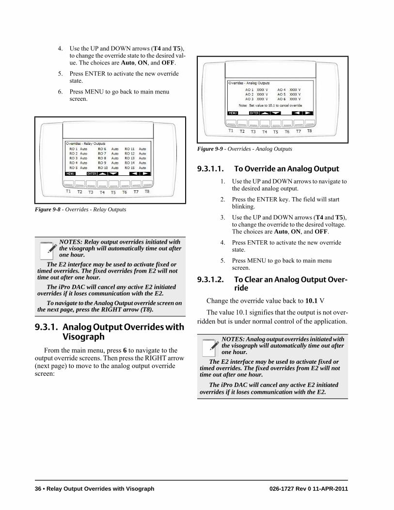
4. Use the UP and DOWN arrows (T4 and T5), to change the override state to the desired val-ue. The choices are Auto, ON, and OFF.
5. Press ENTER to activate the new override state.
6. Press MENU to go back to main menu screen.
9.3.1. Analog Output Overrides with Visograph
From the main menu, press 6 to navigate to the output override screens. Then press the RIGHT arrow (next page) to move to the analog output override screen:
9.3.1.1. To Override an Analog Output
1. Use the UP and DOWN arrows to navigate to the desired analog output.
2. Press the ENTER key. The field will start blinking.
3. Use the UP and DOWN arrows (T4 and T5), to change the override to the desired voltage. The choices are Auto, ON, and OFF.
4. Press ENTER to activate the new override state.
5. Press MENU to go back to main menu screen.
9.3.1.2. To Clear an Analog Output Over-ride
Change the override value back to 10.1 V
The value 10.1 signifies that the output is not over-ridden but is under normal control of the application.
Figure 9-8 - Overrides - Relay Outputs
NOTES: Relay output overrides initiated with the visograph will automatically time out after one hour.
The E2 interface may be used to activate fixed or timed overrides. The fixed overrides from E2 will not time out after one hour.
The iPro DAC will cancel any active E2 initiated overrides if it loses communication with the E2.
To navigate to the Analog Output override screen on the next page, press the RIGHT arrow (T8).
Figure 9-9 - Overrides - Analog Outputs
NOTES: Analog output overrides initiated with the visograph will automatically time out after one hour.
The E2 interface may be used to activate fixed or timed overrides. The fixed overrides from E2 will not time out after one hour.
The iPro DAC will cancel any active E2 initiated overrides if it loses communication with the E2.
36 • Relay Output Overrides with Visograph 026-1727 Rev 0 11-APR-2011


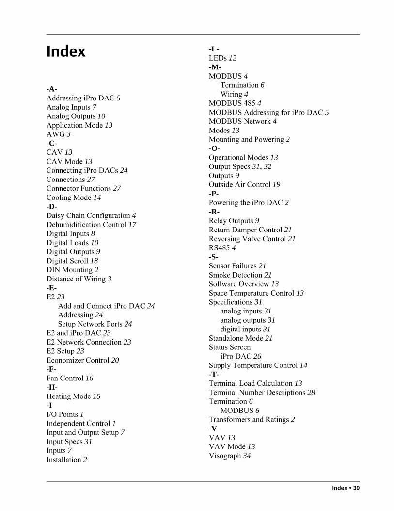
Index
-A-Addressing iPro DAC 5Analog Inputs 7Analog Outputs 10Application Mode 13AWG 3-C-CAV 13CAV Mode 13Connecting iPro DACs 24Connections 27Connector Functions 27Cooling Mode 14-D-Daisy Chain Configuration 4Dehumidification Control 17Digital Inputs 8Digital Loads 10Digital Outputs 9Digital Scroll 18DIN Mounting 2Distance of Wiring 3-E-E2 23
Add and Connect iPro DAC 24Addressing 24Setup Network Ports 24
E2 and iPro DAC 23E2 Network Connection 23E2 Setup 23Economizer Control 20-F-Fan Control 16-H-Heating Mode 15-II/O Points 1Independent Control 1Input and Output Setup 7Input Specs 31Inputs 7Installation 2
-L-LEDs 12-M-MODBUS 4
Termination 6Wiring 4
MODBUS 485 4MODBUS Addressing for iPro DAC 5MODBUS Network 4Modes 13Mounting and Powering 2-O-Operational Modes 13Output Specs 31, 32Outputs 9Outside Air Control 19-P-Powering the iPro DAC 2-R-Relay Outputs 9Return Damper Control 21Reversing Valve Control 21RS485 4-S-Sensor Failures 21Smoke Detection 21Software Overview 13Space Temperature Control 13Specifications 31
analog inputs 31analog outputs 31digital inputs 31
Standalone Mode 21Status Screen
iPro DAC 26Supply Temperature Control 14-T-Terminal Load Calculation 13Terminal Number Descriptions 28Termination 6
MODBUS 6Transformers and Ratings 2-V-VAV 13VAV Mode 13Visograph 34
Index • 39
Analog Output Overrides 35, 36Buttons 5Clear Analog Output Override 36Connectivity 5Override Analog Output 36Relay Output Overrides 35VAV Fan Status 34Viewing I/O Configuration 34
analog inputs 34analog outputs 35digital inputs 35relay outputs 35
Viewing Status 34input status 34output status 34
Visograph Connectivity 5-W-Warnings
Analog Inputs 8Analog Outputs 10, 11Output Capacity 32Transformers 31Voltages 32Wire Length 3
Wire Distance 3Wire Gauge/Types 3Wiring 33
40 • iPro DAC Manual 026-1727 Rev 0 11-APR-2011