iPORT PT1000-CL Hardware Guide - ADSTEC
29
Rev 070505 iPORT™ PT1000-CL Hardware Guide
Transcript of iPORT PT1000-CL Hardware Guide - ADSTEC

Rev 070505
iPORT™
PT1000-CL
Hardware Guide

Copyright © 2003-2006 Pleora Technologies Inc. Page 2
Rev 070505
These products are not intended for use in life support appliances, devices, or systems
where malfunction of these products can reasonably be expected to result in personal
injury. Pleora Technologies Inc. (Pleora) customers using or selling these products for
use in such applications do so at their own risk and agree to fully indemnify Pleora for
any damages resulting from such improper use or sale.
© 2003-2007 Pleora Technologies Inc. All information provided in this manual is
believed to be accurate and reliable. No responsibility is assumed by Pleora for its use.
Pleora reserves the right to make changes to this information without notice.
Redistribution of this manual in whole or in part, by any means, is prohibited without
obtaining prior permission from Pleora.

Copyright © 2003-2006 Pleora Technologies Inc. Page 3
Rev 070505
Table of Contents
1.0 Introduction ........................................................................................ 5
2.0 Overview of the iPORT PT1000-CL................................................. 6
2.1 Highlights............................................................................................................ 6
2.2 Models................................................................................................................. 6
2.3 Characteristics and Features ............................................................................... 7
3.0 Connectors........................................................................................... 9
3.1 Camera Link Connector ...................................................................................... 9
3.2 Power and IO Connectors ................................................................................. 10
3.2.1 Power Connector for OEM Board Set .......................................................... 10
3.2.2 IO Connector for OEM Board Set ................................................................ 11
3.2.3 Power Connector for Boxed Unit ................................................................. 12
3.2.4 IO Connector for Boxed Unit ....................................................................... 12
4.0 Signal Handling................................................................................. 14
4.1 PLC Control Blocks.......................................................................................... 14
4.2 PLC Programming Signals ............................................................................... 17
4.3 Camera Interface ............................................................................................... 19
4.3.1 Camera Inputs ............................................................................................... 19
4.3.2 Camera Controls ........................................................................................... 19
4.3.3 Camera Link Serial API................................................................................ 20
4.3.4 CL Serial API Usage..................................................................................... 21
5.0 Mechanical Dimensions.................................................................... 22
5.1 Mechanical Drawings of OEM Board Set ........................................................ 22
5.2 Mechanical Drawings of Boxed Unit ............................................................... 24
6.0 Technical Support ............................................................................ 26
6.1 Revision History ............................................................................................... 26
7.0 Appendix: Legacy Products............................................................. 27
7.1 Characteristics and Features ............................................................................. 28
7.2 PLC Control Block ........................................................................................... 29

Copyright © 2003-2006 Pleora Technologies Inc. Page 4
Rev 070505
List of Figures
Figure 1: Power and IO Connector Locations on the OEM Board Set............................. 10
Figure 2: Power Connector for Boxed Units .................................................................... 12
Figure 3: IO Connector for Boxed Units .......................................................................... 13
Figure 4: iPORT PT1000-CL4 PLC Control Block ......................................................... 15
Figure 5: iPORT PT1000-CL5 PLC Control Block ......................................................... 16
Figure 6: Isometric View of the OEM Board Set ............................................................. 22
Figure 7: Side View of the OEM Board Set ..................................................................... 23
Figure 8: Top View of the OEM Board Set ...................................................................... 23
Figure 9: Front View of the Boxed Units ......................................................................... 24
Figure 10: Rear View of the Boxed Units ........................................................................ 24
Figure 11: Side View of the Boxed Units ......................................................................... 25
Figure 12: Top View of the Boxed Units.......................................................................... 25
Figure 13: iPORT PT1000-CL2 PLC Control Block ....................................................... 29
List of Tables
Table 1: iPORT PT1000-CL4 Characteristics and Features............................................... 7
Table 2: iPORT PT1000-CL5 Characteristics and Features............................................... 8
Table 3: Camera Link Connector Pin-Out (looking at IP Engine) ..................................... 9
Table 4: Power Connector Pin-Out for the OEM Board Set ............................................ 10
Table 5: IO Connector Pin-Out for OEM Board Set ........................................................ 11
Table 6: Power Connector Pin-Out for Boxed Units ........................................................ 12
Table 7: IO Connector Pin-Out for Boxed iPORT PT1000-CL4 ..................................... 13
Table 8: IO Connector Pin-Out for Boxed iPORT PT1000-CL5 ..................................... 13
Table 9: iPORT PT1000-CL PLC Input Signals .............................................................. 17
Table 10: iPORT PT1000-CL PLC Output Signals.......................................................... 18
Table 11: Characteristics and Features of the iPORT PT1000-CL2................................. 28

Copyright © 2003-2006 Pleora Technologies Inc. Page 5
Rev 070505
1.0 Introduction
This hardware guide describes how to access and use features specific to Pleora’s iPORT
PT1000-CL IP Engine. The engine is available as both an OEM board set and a boxed
unit. Therefore, some of the descriptions in this guide, particularly those dealing with
physical aspects, have two sections, one of each form factor of the engine.
For an overview of how to use IP Engine, see the iPORT Quick Start Guide. For detailed
information about the PLC, see the iPORT Programmable Logic Controller reference
guide.

Copyright © 2003-2006 Pleora Technologies Inc. Page 6
Rev 070505
2.0 Overview of the iPORT PT1000-CL
2.1 Highlights
The iPORT PT1000-CL IP Engine delivers the core set of features offered in all iPORT
IP Engines, plus a connector and extended functions tailored specifically for Camera
Link® cameras. It interfaces to all cameras that comply with the Camera Link base
configuration standard.
The engine grabs data from a Camera Link camera, converts it to IP quickly and
efficiently, and sends it to PCs over GigE links or LANs. The grabber circuitry in the
PT1000-CL removes horizontal and vertical blank times, which helps maximize
bandwidth usage in the GigE connection.
Data is streamed continuously over inexpensive Cat-5 copper cable with low and
consistent latency (delay) at the full, 1-Gb/s line rate. At the PC, the Cat-5 cable plugs
into a standard GigE NIC (network interface card/chip), eliminating the need for a frame
grabber.
The PT1000-CL also handles control signals from the PC and other system elements.
These signals are routed through a PLC (programmable logic controller) that allows users
to precisely measure and control the operation of conveyors, encoders, cameras, and other
components – either independently from or in conjunction with the host PC on the
network.
2.2 Models
The standard model of the iPORT PT1000-CL IP Engine is known as the iPORT
PT1000-CL4. This model is available as an OEM board set or boxed unit.
Pleora also offers a variant of the boxed model known as the iPORT PT1000-CL5. It is
not available as an OEM board set.
The only difference between the two is their IO pin-out. The CL4 has two TTL IOs and
one LVDS input; the CL5 has three TTL IOs and no LVDS input. See Sections 3.2.2 and
3.2.4 of this guide for more detail.
Hardware tap reconstruction is also offered in the iPORT PT1000-CL4-T and the iPORT
PT1000-CL5-T. Contact Pleora to determine which tap architectures are currently
supported. Besides hardware tap reconstruction these models are identical to their parent
models.
Note: Information about the first-generation version of the iPORT PT1000-CL, known as
the iPORT PT1000-CL2, is available in the Appendix. This model is not available to new
customers and is no longer being upgraded with new features.

Copyright © 2003-2006 Pleora Technologies Inc. Page 7
Rev 070505
2.3 Characteristics and Features
Table 1 and Table 2 list key characteristics and features in the iPORT PT1000-CL4 and
iPORT PT1000-CL5, respectively.
Available as OEM Yes
Available as Boxed Yes
Onboard Memory16 MB (Std)
64 MB (Opt)
TTL Inputs 2 (Note 3)
TTL Outputs 2
LVDS Inputs 1
Optically Isolated Inputs 1
Optically Isolated Outputs 1
Camera Control Outputs 4 x LVDS
Pulse Generators (timers) 4
Rescaler (16-bit) 1
Delayers 1
General Purpose Counters 1
Input Debouncing Yes
Timestamp Generator Yes
Timestamp Trigger Yes
Software Controlled IO 4
GPIO Interrupts FIFO Yes
Serial Ports (UART)1 x LVDS (CL)
1 x TTL (GPIO) (3.66)
PT1000-CL4 Supply Voltage
Min: 4.5 V
Typ: 5 V
Max: 16 V
Power Consumption
(measured at 10V)
Typ: 2.6 W
Max: 2.6 W
Operating TemperatureMin: 0 °C
Max: 70 °C
Storage TemperatureMin: -40 °C
Max: 125 °C
Inputs/Outputs
Programmable Logic Control
Hardware
Other
Notes:All features supported by iPORT SDK 2.2.0 and higher
(x.xx) - Available since firmware version x.xx
4 - NRE or other charges may apply. Contact Pleora.
NA - Not applicable
1 - RGB supported as single-tap, 24 bits
3 - Other configurations available. Contact Pleora.
Ethernet Bandwidth 1 Gb/s
Unicast Yes
Multicast Yes
Static Configuration Yes (4.01)
BOOTP Yes
DHCP Yes (4.06)
Number of Data Channels 1
Video Input Base Camera Link
InterlacedYes (SPARE must be used
as FID)
Progressive Scan Yes
Area Scan Yes
Line Scan Yes
Color
RGB
Bayer
YUV 4:2:2
Monochrome Yes
PT1000-CL4 Data Output Formats
Grayscale
Bayer
RGB
YUV 4:2:2
Pixel Depth (bits) 8, 10, 12, 14, 16, 24
Pixel ClockMin: 20 MHz
Max: 66 MHz
Taps per Data Channel 2 (Note 1)
Image Width (pixels)
(must be multiple of 4)
Min: 4
Default: 640
Max: 16,380
Image Height (pixels)
Min: 1
Default: 480
Max: 16,383
Windowing Yes
Decimation Yes
Decimation by Block Yes
Tap Reconstruction Optional (Note 4)
Data Port Mapping Yes
Pixel Shifting Yes
Pixel Inversion Yes
Recording/Playback Yes
Frame Grabber
Table 1: iPORT PT1000-CL4 Characteristics and Features

Copyright © 2003-2006 Pleora Technologies Inc. Page 8
Rev 070505
Available as OEM No
Available as Boxed Yes
Onboard Memory16 MB (Std)
64 MB (Opt)
TTL Inputs 3
TTL Outputs 3
Optically Isolated Inputs 1
Optically Isolated Outputs 1
Camera Control Outputs 4 x LVDS
Pulse Generators (timers) 4
Rescaler (16-bit) 1
Delayers 1
General Purpose Counters 1
Input Debouncing Yes
Timestamp Generator Yes
Timestamp Trigger Yes
Software Controlled IO 4
GPIO Interrupts FIFO Yes
Serial Ports (UART)1 x LVDS (CL)
1 x TTL (GPIO) (3.66)
PT1000-CL5 Supply Voltage
Min: 4.5 V
Typ: 5 V
Max: 16 V
Power Consumption
(measured at 10V)
Typ: 2.6 W
Max: 2.6 W
Operating TemperatureMin: 0 °C
Max: 70 °C
Storage TemperatureMin: -40 °C
Max: 125 °C
Other
Inputs/Outputs
Programmable Logic Control
Hardware
Notes:
NA - Not applicable
1 - RGB supported as single-tap, 24 bits
3 - Other configurations available. Contact Pleora.
(x.xx) - Available since firmware version x.xx
4 - NRE or other charges may apply. Contact Pleora.
All features supported by iPORT SDK 2.2.0 and higher
Ethernet Bandwidth 1 Gb/s
Unicast Yes
Multicast Yes
Static Configuration Yes (4.01)
BOOTP Yes
DHCP Yes (4.06)
Number of Data Channels 1
Video Input Base Camera Link
InterlacedYes (SPARE must be used
as FID)
Progressive Scan Yes
Area Scan Yes
Line Scan Yes
Color
RGB
Bayer
YUV 4:2:2
Monochrome Yes
PT1000-CL5 Data Output Formats
Grayscale
Bayer
RGB
YUV 4:2:2
Pixel Depth (bits) 8, 10, 12, 14, 16, 24
Pixel ClockMin: 20 MHz
Max: 66 MHz
Taps per Data Channel 2 (Note 1)
Image Width (pixels)
(must be multiple of 4)
Min: 4
Default: 640
Max: 16,380
Image Height (pixels)
Min: 1
Default: 480
Max: 16,383
Windowing Yes
Decimation Yes
Decimation by Block Yes
Tap Reconstruction Optional (Note 4)
Data Port Mapping Yes
Pixel Shifting Yes
Pixel Inversion Yes
Recording/Playback Yes
Frame Grabber
Table 2: iPORT PT1000-CL5 Characteristics and Features

Copyright © 2003-2006 Pleora Technologies Inc. Page 9
Rev 070505
3.0 Connectors
This section provides information about the Camera Link, power, and IO connectors on
the OEM and boxed versions of the iPORT PT1000-CL IP engine. The Ethernet
connector is a standard RJ-45 plug.
3.1 Camera Link Connector
All iPORT PT1000-CL models use the same high-density, 26-pin MDR26 standard
female Camera Link connector. The mating part number is the 3M 224-31 series. The
connector uses the 3M 14X26-SZLB-XXX-0LC cable, or equivalent. Table 3 maps the
pins in the Camera Link connector to signals.
Pin Camera Link Signal
1 Inner Shield
14 Inner Shield
25 X0-
12 X0+
24 X1-
11 X1+
23 X2-
10 X2+
22 Xclk-
9 Xclk+
21 X3-
8 X3+
20 SerTC+
7 SerTC-
19 SerTFG-
6 SerTFG+
18 CC1-
5 CC1+
17 CC2+
4 CC2-
16 CC3-
3 CC3+
15 CC4+
2 CC4-
13 Inner Shield
26 Inner Shield
Table 3: Camera Link Connector Pin-Out (looking at IP Engine)

Copyright © 2003-2006 Pleora Technologies Inc. Page 10
Rev 070505
3.2 Power and IO Connectors
3.2.1 Power Connector for OEM Board Set
The iPORT PT1000-CL4 OEM board set accepts power supply voltages of from 4.5 V to
16 V (regulated). The connector, shown as J2 on the left-hand side of Figure 1, is a
Molex 4-pin 6373 Series (22-23-2041). The part mates with the Molex 4-pin shell (22-
01-3047) and the Molex crimp pin (08-55-0102). Table 4 lists the four pins in this
connector and describes the function of each.
Ethernet
J2
J12
Figure 1: Power and IO Connector Locations on the OEM Board Set
Pin Signal Name Type Description
1 GND PWR Ground
2 VIN PWR Power supply voltage in (4.5 V to 16 V regulated)
3 VIN PWR Power supply voltage in (4.5 V to 16 V regulated)
4 GND PWR Ground
Table 4: Power Connector Pin-Out for the OEM Board Set

Copyright © 2003-2006 Pleora Technologies Inc. Page 11
Rev 070505
3.2.2 IO Connector for OEM Board Set
The IO connector for the iPORT PT1000-CL4 OEM board set is a 16-pin, Samtec 2-mm
male header (TMM-108-01-G-D-SM). The mating connectors are in the Samtec MMS-
108-02-xx-xx series. The mating flat cables are in the Samtec TCSD series (TCSD-08-
xxxxxxx). The connector is shown as J12 on the right-hand side of Figure 1. Table 5 lists
the 16 pins in the connector, and describes the function of each.
Pin Signal Name Description
1 GND Ground
2 VCC 3.3 V at 250 mA max�
3 OPT0_OUT- Optically isolated negative output
4 OPT0_OUT+ Optically isolated positive output
5 TTL_IN[0] TTL input 0
6 TTL_OUT[0] TTL output 0
7 TTL_OUT[1] TTL output 1
8 TTL_IN[1] TTL input 1
9 N/C No connect (leave unconnected)
10 N/C No connect (leave unconnected)
12 OPT0_IN- Optically isolated negative input
12 OPT0_IN+ Optically isolated positive input
13 LVDS_IN- Low-voltage differential signal negative input
14 LVDS_IN+ Low-voltage differential signal positive input
15 GND Ground
16 VCC 3.3 V at 250 mA max*
Table 5: IO Connector Pin-Out for OEM Board Set
� These VCC supplies are not recommended for analog circuitry. Analog circuitry should be driven from a
separate 3.3 V supply.

Copyright © 2003-2006 Pleora Technologies Inc. Page 12
Rev 070505
3.2.3 Power Connector for Boxed Unit
The iPORT PT1000-CL boxed units both use the same Hirose 6-pin power connector
shown in Figure 2. The part number is HR10A-7R-6P. The mating part number is
HR10A-7P-6S. Table 6 lists the six pins in the connector and describes the function of
each.
Figure 2: Power Connector for Boxed Units
Pin Description
1 Vin 4.5 V to 16 V regulated
2 Vin 4.5 V to 16 V regulated
3 Vin 4.5 V to 16 V regulated
4 Ground
5 Ground
6 Ground
Table 6: Power Connector Pin-Out for Boxed Units
3.2.4 IO Connector for Boxed Unit
The iPORT PT1000-CL boxed units both use the same Hirose 12-pin IO connector
shown in Figure 3. The part number for this connector is HR10A-10R-12S; the mating
part number is HR10A-10P-12P.
Table 7 describes the function of each pin in the iPORT PT1000-CL4 model. Table 8
describes the function of each pin in the iPORT PT1000-CL5 model. The only difference
is on pins 9 and 10. On the CL4, these pins are used for an LVDS input. On the CL5, they
are used to support a third TTL IO.

Copyright © 2003-2006 Pleora Technologies Inc. Page 13
Rev 070505
Figure 3: IO Connector for Boxed Units
Pin Signal Name Description
1 OPT0_OUT- Optically isolated negative output
2 OPT0_OUT+ Optically isolated positive output
3 TTL_IN[0] TTL input 0
4 TTL_OUT[0] TTL output 0
5 TTL_OUT[1] TTL output 1
6 TTL_IN[1] TTL input 1
7 OPT0_IN- Optically isolated negative input
8 OPT0_IN+ Optically isolated positive input
9 LVDS_IN- Low-voltage differential signal negative input
10 LVDS_IN+ Low-voltage differential signal positive input
11 GND Ground
12 VCC 3.3 V at 100 mA max
Table 7: IO Connector Pin-Out for Boxed iPORT PT1000-CL4
Pin Signal Name Description
1 OPT0_OUT- Optically isolated negative output
2 OPT0_OUT+ Optically isolated positive output
3 TTL_IN[0] TTL input 0
4 TTL_OUT[0] TTL output 0
5 TTL_OUT[1] TTL output 1
6 TTL_IN[1] TTL input 1
7 OPT0_IN- Optically isolated negative input
8 OPT0_IN+ Optically isolated positive input
9 TTL_OUT[2] TTL output 2
10 TTL_IN[2] TTL input 2
11 GND Ground
12 VCC 3.3 V at 100 mA max
Table 8: IO Connector Pin-Out for Boxed iPORT PT1000-CL5

Copyright © 2003-2006 Pleora Technologies Inc. Page 14
Rev 070505
4.0 Signal Handling
The iPORT PT1000-CL handles the signals in much the same way as other iPORT IP
engine models. There are a few minor differences, which are described in this section.
4.1 PLC Control Blocks
The Programmable Logic Controller (PLC) in the iPORT PT1000-CL routes signals
through a sophisticated PLC Control Block. Figure 4 shows the PLC Control Block
signals for the iPORT PT1000-CL4 model. Figure 5 shows the PLC Control Block
signals for the iPORT PT1000-CL5 model.

Copyright © 2003-2006 Pleora Technologies Inc. Page 15
Rev 070505
Feedback Inputs
Input Signal Routing Matrix
trigger
trigger
trigger
trigger
Figure 4: iPORT PT1000-CL4 PLC Control Block

Copyright © 2003-2006 Pleora Technologies Inc. Page 16
Rev 070505
Feedback Inputs
Input S
ignal R
outing M
atr
ix
trig
ger
trig
ger
trig
ger
trig
ger
Figure 5: iPORT PT1000-CL5 PLC Control Block

Copyright © 2003-2006 Pleora Technologies Inc. Page 17
Rev 070505
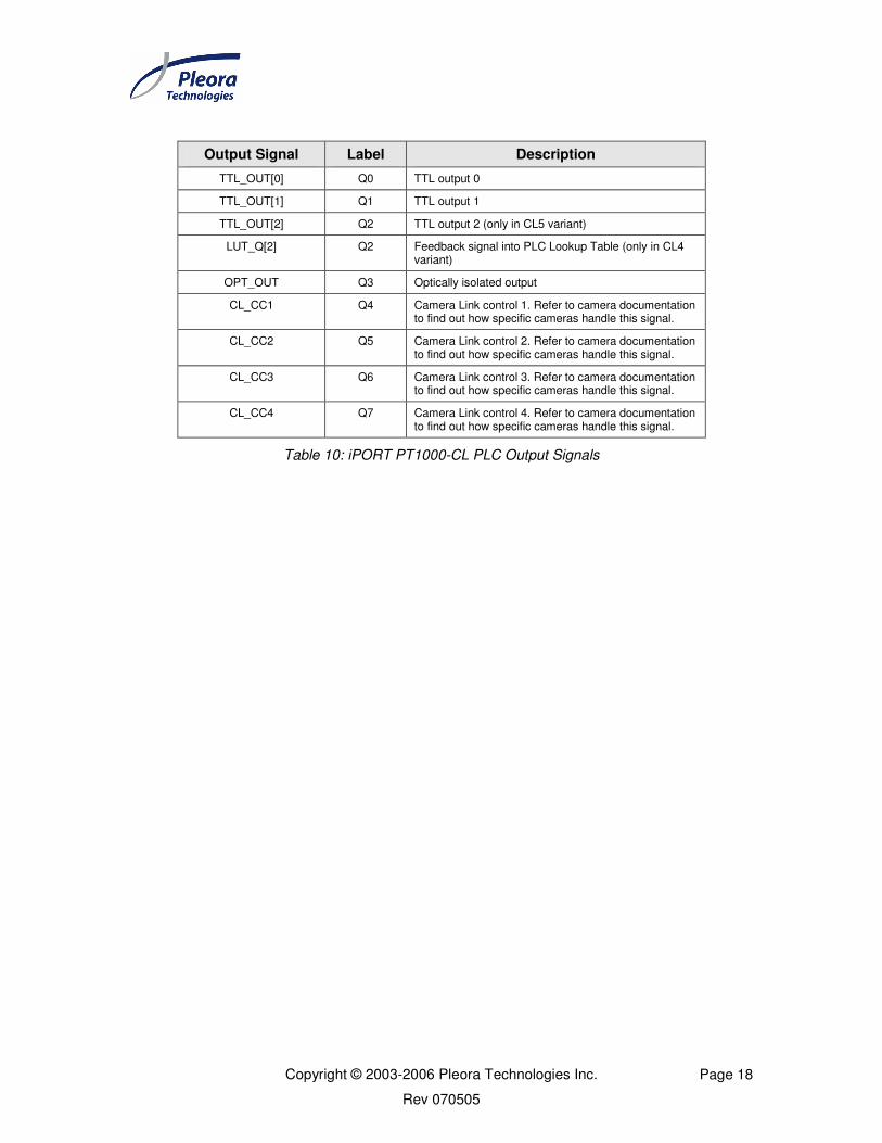
4.2 PLC Programming Signals
Table 9 and Table 10 list the PLC input and output programming signals that are specific
to the iPORT PT1000-CL IP engine. The labels used for inputs to the PLC Lookup Table
depend on the input configured in the PLC Lookup Table dialog.
Input Signal Description
TTL_IN[0] TTL input 0
TTL_IN[1] TTL input 1
TTL_IN[2] TTL input 2 (only available in CL5 variant)
LVDS_IN LVDS input (only available in CL4 variant)
OPTO_IN Optically isolated input
CL_FVAL Camera Link Frame Valid signal. Refer to camera documentation to find out how specific cameras handle this signal.
CL_LVAL Camera Link Line Valid signal. Refer to camera documentation to find out how specific cameras handle this signal.
CL_DVAL Camera Link Data Valid signal. Refer to camera documentation to find out how specific cameras handle this signal.
CL_SPR Camera Link spare signal. Refer to camera documentation to find out how specific cameras handle this signal
Table 9: iPORT PT1000-CL PLC Input Signals
Copyright © 2003-2006 Pleora Technologies Inc. Page 18
Rev 070505
Output Signal Label Description
TTL_OUT[0] Q0 TTL output 0
TTL_OUT[1] Q1 TTL output 1
TTL_OUT[2] Q2 TTL output 2 (only in CL5 variant)
LUT_Q[2] Q2 Feedback signal into PLC Lookup Table (only in CL4 variant)
OPT_OUT Q3 Optically isolated output
CL_CC1 Q4 Camera Link control 1. Refer to camera documentation to find out how specific cameras handle this signal.
CL_CC2 Q5 Camera Link control 2. Refer to camera documentation to find out how specific cameras handle this signal.
CL_CC3 Q6 Camera Link control 3. Refer to camera documentation to find out how specific cameras handle this signal.
CL_CC4 Q7 Camera Link control 4. Refer to camera documentation to find out how specific cameras handle this signal.
Table 10: iPORT PT1000-CL PLC Output Signals

Copyright © 2003-2006 Pleora Technologies Inc. Page 19
Rev 070505
4.3 Camera Interface
4.3.1 Camera Inputs
All Camera Link cameras have four standard input signals: Camera Link Frame Valid
(FVAL), Camera Link Line Valid (LVAL), Camera Link Data Valid (DVAL) and
Camera Link Spare (SPARE). FVAL and LVAL can be activated by positive or negative
signal edges, or by high or low levels. DVAL can be activated by high or low levels. For
information on the polarity and type of the signals required to support specific camera
models, refer to camera documentation.
The labels for these input signals in the PLC Control Block programming language
depend on the inputs configured in the PLC Lookup Table dialog.
4.3.2 Camera Controls
The iPORT PT1000-CL can send commands to cameras through the Camera Link camera
control signals. The Camera Link specification provides four camera control signals,
which can be used in a variety of ways. For information on how your camera uses them,
refer to its documentation.
The labels of the control outputs to the camera in the PLC Control Block programming
language are:
o Q4, for Camera Link CC1
o Q5, for Camera Link CC2
o Q6, for Camera Link CC3
o Q7, for Camera Link CC4

Copyright © 2003-2006 Pleora Technologies Inc. Page 20
Rev 070505
4.3.3 Camera Link Serial API
This serial API is an implementation of the standard Camera Link API for serial
communications. Refer to Annex B of the Camera Link specification for more
information about this API.
The API dynamic-linked library (DLL) is named as dictated by the Camera Link
standard: (format: clser*.dll): clserptk.dll. The file is installed in the
C:\WINNT\system32 directory.1
The functions in the DLL are:
• clSerialInit: Initialize the serial communication for a specific board.
• clSerialRead: Read bytes from the camera.
• clSerialWrite: Write bytes to the camera.
• clSerialClose: Close the serial communication.
• clFlushPort: Flush all the data available on a port.
• clGetErrorText: Return a human readable version of an error code.
• clGetManufacturerInfo: Return the name of the manufacturer.
• clGetNumBytesAvail: Return the number of bytes available for reading.
• clGetNumSerialPorts: Return the number of serial ports available on the system.
• clGetSupportedBaudRates: Return the supported baud rates.
• clSetBaudRate: Change the baud rate when opening the next port.
1 Some applications may try to search for the clser*.dll files elsewhere than from C:\WINNT\System32.
Please refer to that application’s documentation to find where to copy the clserptk.dll file.

Copyright © 2003-2006 Pleora Technologies Inc. Page 21
Rev 070505
4.3.4 CL Serial API Usage
When an application loads the Camera Link DLL, the DLL will search for and list all IP
engines currently on the network. The list is compiled from a zero-based index in the
order that the IP engines are found. Note that the order may change, depending on the
available engines. IP engines that are dynamically discovered on the network will be
named using the following format:
MODE #INDEX IP_ADDRESS
MODE: either Driver or UDP.
INDEX: The index of the network adapter (if there is more that one adapter)
IP_ADDRESS: The IP address of the engine, or “Direct” (if the device is directly
connected to a High-Performance Driver card).
When loading, the Camera Link DLL will also attempt to load a file named Config.xml
from the current directory of the application using the DLL. If the file is present, the IP
engine information it contains will be added before the IP engines that are discovered on
the network. The Config.xml file can be created using Pleora’s Coyote application and
must be saved in the directory of the application using the DLL.
Each configuration is then accessible with a zero-based index corresponding to the
available IP engine configurations of the Configuration file.

Copyright © 2003-2006 Pleora Technologies Inc. Page 22
Rev 070505
5.0 Mechanical Dimensions
This section provides mechanical drawings and measurements of the OEM and boxed
versions of the iPORT PT1000-CL IP Engine. The measurements are in inches unless
otherwise specified. The measurements have the following tolerances, depending on the
number of significant digits provided:
.X ±0.1
.XX ±0.01
.XXX ±0.005
5.1 Mechanical Drawings of OEM Board Set
Figure 6 to Figure 8 are mechanical drawings of the iPORT PT1000-CL OEM boards.
The main board and daughter board are both 0.0625 inches thick. The maximum
secondary component height on both boards is 0.08 inches, unless otherwise specified in
the drawings.
Figure 6: Isometric View of the OEM Board Set

Copyright © 2003-2006 Pleora Technologies Inc. Page 23
Rev 070505
Figure 7: Side View of the OEM Board Set
Figure 8: Top View of the OEM Board Set

Copyright © 2003-2006 Pleora Technologies Inc. Page 24
Rev 070505
5.2 Mechanical Drawings of Boxed Unit
The drawings in Figure 9 to Figure 12 show views for the boxed version of the PT1000-
CL. The enclosure is made from anodized aluminum and provides four mounting holes.
The mounting hole diameter and slot width are both 0.17 +/- 0.01 inches.
Figure 9: Front View of the Boxed Units
Figure 10: Rear View of the Boxed Units

Copyright © 2003-2006 Pleora Technologies Inc. Page 25
Rev 070505
Figure 11: Side View of the Boxed Units
Figure 12: Top View of the Boxed Units

Copyright © 2003-2006 Pleora Technologies Inc. Page 26
Rev 070505
6.0 Technical Support
For additional help, see the Technical Support section in the iPORT Quick Start Guide.
6.1 Revision History
Revision Date Description
2.1.1 January 2003 - Creation
2.1.3 February 2004 - Modified text to reflect iPORT Software V2.1.3
2.1.4 April 2005 - Added PLC diagrams for CL4 and CL5
- Modified text to reflect iPORT Software V2.1.4
060206 February 2006 - Modified text to reflect iPORT Software V2.2.0
- Added Characteristics and Features table
- Reordered sections
- Updated formatting to comply with new Pleora template
- Added Revision History table
- Created Appendix for legacy products
061106 November 2006 - Revised title
- Camera configuration removed
- Updated Features tables
- Updated Figure 6 annotation
- Added the iPORT PT1000-CL4-T and iPORT PT1000-CL5-T to section 2.2
- Miscellaneous minor changes
070505 May 2007 - Corrected the Camera Link pinouts

Copyright © 2003-2006 Pleora Technologies Inc. Page 27
Rev 070505
7.0 Appendix: Legacy Products
This appendix is a brief overview of the features and PLC block in the iPORT PT1000-
CL2 IP Engine, the first-generation version of the iPORT PT1000-CL. This model is not
available to new customers and is not being upgraded with new features. Table 11 lists its
key characteristics and features and Figure 13 shows its PLC Control Block.

Copyright © 2003-2006 Pleora Technologies Inc. Page 28
Rev 070505
7.1 Characteristics and Features
Available as OEM Yes
Available as Boxed Yes
Onboard Memory16 MB (Std)
64 MB (Opt)
TTL Inputs 2
TTL Outputs 2
LVDS Inputs 1
Optically Isolated Inputs 1
Optically Isolated Outputs 1
Camera Control Outputs 4 x LVDS
Pulse Generators (timers) 2
Rescaler (12-bit) 1 (3.50)
Delayers 1 (3.50)
General Purpose Counters 1 (3.50)
Input Debouncing Yes (3.50)
Timestamp Generator Yes (3.00)
Timestamp Trigger Yes (3.50)
Software Controlled IO 4
GPIO Interrupts FIFO Yes (3.50)
Serial Ports (UART) 1 x LVDS (CL)
PT1000-CL2 Supply Voltage
Min: 4.5 V
Typ: 5 V
Max: 16 V
Power Consumption
(measured at 10V)
Typ: 2.6 W
Max: 2.6 W
Operating TemperatureMin: 0 °C
Max: 70 °C
Storage TemperatureMin: -40 °C
Max: 125 °C
Other
Inputs/Outputs
Programmable Logic Control
Hardware
Notes:
NA - Not applicable
1 - RGB supported as single-tap, 24 bits
(x.xx) - Available since firmware version x.xx
All features supported by iPORT SDK 2.2.0 and higher
Ethernet Bandwidth 1 Gb/s
Unicast Yes
Multicast Yes
BOOTP Yes
Number of Data Channels 1
Video Input Base Camera Link
InterlacedYes (SPARE must be used
as FID)
Progressive Scan Yes
Area Scan Yes
Line Scan Yes
Color
RGB
Bayer
YUV 4:2:2
Monochrome Yes
PT1000-CL2 Data Output Formats
Grayscale
Bayer
RGB
YUV 4:2:2
Pixel Depth (bits) 8, 10, 12, 14, 16, 24
Pixel ClockMin: 20 MHz
Max: 66 MHz
Taps per Data Channel 2 (Note 1)
Image Width (pixels)
(must be multiple of 4)
Min: 4
Default: 640
Max: 16,380
Image Height (pixels)
Min: 1
Default: 480
Max: 16,383
Windowing Yes
DecimationBayer: Yes (3.24)
Others: Yes
Decimation by Block Yes (3.24)
Data Port Mapping Yes (3.16)
Pixel Shifting Yes (3.16)
Pixel Inversion Yes (3.16)
Recording/Playback Yes (3.14)
Frame Grabber
Table 11: Characteristics and Features of the iPORT PT1000-CL2

Copyright © 2003-2006 Pleora Technologies Inc. Page 29
Rev 070505
7.2 PLC Control Block
Q[17:16], Q[11:7], Q[3]8:1
16:1
16:1
16:1
16:1
16:1
16:1
16:1
16:1
TTL_OUT[0]
CL_CC1
pg_out[0]
LI[0]
LI[1]
LI[2]
LI[3]
LI[4]
LI[5]
LI[6]
LI[7]
TTL_OUT[1]
OPT_OUT
CL_CC2
CL_CC3
CL_CC4
Q[17:0]
GPIO_TRIG
GPIO_LVAL
GPIO_FVAL
rsl_out
gp_cnt_eq
gp_cnt_gt
LUT_Q[2]
OPT_OUT
CL_CC3
CL_CC4
del_out
TTL_IN[0]
TTL_IN[1]
LVDS_IN
OPT_IN
CL_FVAL
CL_LVAL
CL_DVAL
CL_SPR
GPIO_CTRL[0]
GPIO_CTRL[1]
GPIO_CTRL[2]
GPIO_CTRL[3]
Feedback Inputs
S+D
S
S
S
S
S+D
S+D
S : Synchronization Bloc
: Synchronization and Debouncing Bloc
Input Signal Routing Matrix
Delayer
Rescaler
12-bit Multiplier
in
bckp
in
ref
8:1
4:1
pg_out[3:0]
Q[17:16], Q[11:7], Q[3]
pg_out[3:0], rsl_out
Q[0]
Q[1]
Q[2]
Q[3]
Q[4]
Q[5]
Q[6]
Q[7]
Q[12]
Q[13]
Q[14]
LUT
8-to-18
rsl_out
del_out
pg_out[1]
ts_trig[3:0]
TimeStamp
Counter
TimeStamp
Trigger
Generator
General
Purpose
Counter
up
clr
down
gp_cnt_eqgp_cnt_gt
ts_trig[3:0]
clr
set
Pulser_Gen0
Pulse_Gen1
Q[9]
Q[8]
pg_out[0]
pg_out[1]
trigger
trigger
5:1
Q[17:16], Q[11:7], Q[3]8:1
Q[17:16], Q[11:7], Q[3]8:1
8:1
GPIO_CNT
[31:0]
REG_VALUE[31:0]
REG_TRIG[3:0]
Interrupt
FIFO TIME[31:0]
Q[3], Q[7], Q[10], Q[15]int
ts_cnt[31:0]
gp_cnt[31:0]
ts_cnt[31:0]
gp_cnt[31:0]
time
mask
gpio_cnt[31:0]
LI[7:0]
GPIO_IRQ
MASK[7:0]
ID[3:0]
gpio_cnt[31:0]
S+D
S+D
Q[17]
Q[16]
LUT_Q[2]
Figure 13: iPORT PT1000-CL2 PLC Control Block