IP•Express Router User’s Guide · 2012-10-15 · • Optional Integrated E1 DSU/CSU for direct...
153
IP•Express Router User’s Guide Engage Communication, Inc.
Transcript of IP•Express Router User’s Guide · 2012-10-15 · • Optional Integrated E1 DSU/CSU for direct...
IP•Express Router
User’s Guide
EngageCommunication, Inc.
Engage Communication, Inc.9053 Soquel Drive Aptos, California 95003Ph: 831.688.1021 Fax: 831.688.1421www.engagecom.com June 3, 2000
IP•Express Router
User’s Guide
Product WarrantySeller warrants to Buyer that any unit shipped to Buyer,under normal and proper use, be free from defects inmaterial and workmanship for a period of 12 months fromthe date of shipment to Buyer. This warranty will not beextended to items repaired by anyone other than the Selleror its authorized agent. The foregoing warranty is exclu-sive and in lieu of all other warranties of merchantability,fitness for purpose, or any other type, whether express orimplied.
Remedies and Limitation of LiabilityA. All claims for breach of the foregoing warranty shall
be deemed waived unless notice of such claim isreceived by Seller during the applicable warrantyperiod and unless the items to be defective are re-turned to Seller within thirty (30) days after suchclaim. Failure of Seller to receive written notice of anysuch claim within the applicable time period shall bedeemed an absolute and unconditional waiver bybuyer of such claim irrespective of whether the factsgiving rise to such a claim shall have been discoveredor whether processing, further manufacturing, otheruse or resale of such items shall have then taken place.
B. Buyer’s exclusive remedy, and Seller’s total liability,for any and all losses and damages arising out of anycause whatsoever (whether such cause be based incontract, negligence, strict liability, other tort or oth-erwise) shall in no event exceed the repair price of thework to which such cause arises. In no event shallSeller be liable for incidental, consequential, or puni-tive damages resulting from any such cause. Sellermay, at its sole option, either repair or replace defec-tive goods or work, and shall have no further obliga-tions to Buyer. Return of the defective items to Sellershall be at Buyer’s risk and expense.
C. Seller shall not be liable for failure to perform itsobligations under the contract if such failure resultsdirectly or indirectly from, or is contributed to by anyact of God or of Buyer; riot; fire; explosion; accident;flood; sabotage; epidemics; delays in transportation;lack of or inability to obtain raw materials, compo-nents, labor, fuel or supplies; governmental laws,regulations or orders; other circumstances beyondSeller’s reasonable control, whether similar or dis-similar to the foregoing; or labor trouble, strike, lock-
out or injunction (whether or not such labor event iswithin the reasonable control of Seller).
FCC Radio Frequency Interference Statement
Note: This equipment has been tested and found tocomply with the limits for a Class A digital device,pursuant to Part 15 of the FCC Rules. These limits aredesigned to provide reasonable protection againstharmful interference when the equipment is operated in acommercial environment. This equipment generates,uses, and can radiate radio frequency energy and, if notinstalled and used in accordance with the instructionmanual, may cause harmful interference to radiocommunications. Operation of this equipment in aresidential area is likely to cause harmful interference inwhich case the user will be required to correct theinterference at his own expense. Shielded cables mustbe used with Engage routers to ensure compliancewith FCC Part 15 Class A limits.
Copyright NoticeCopyright ©1989-1998 Engage Communication, Inc.
All rights reserved. This document may not, in part or inentirety, be copied, photocopied, reproduced, translated, orreduced to any electronic medium or machine-readable formwithout first obtaining the express written consent of EngageCommunication. Restricted rights legend: Use, duplication, ordisclosure by the U.S. government is subject to restrictions setforth in subparagraph (c)(1)(ii) of the Rights in Technical Dataand Computer Software clause in DFARS 52.227-7013 and insimilar clauses in the FAR and NASA FAR Supplement.
Information in this document is subject to change withoutnotice and does not represent a commitment on the part ofEngage Communication.
The software described in this document is furnished undera license agreement or non-disclosure agreement. Thesoftware may be used or copied only in accordance with theterms of the agreement. It is against the law to copy thesoftware on any medium except as specifically allowed inthe license or non-disclosure agreement.
1Table of Contents
Table of Contents
Chapter 1: Introduction ........................................... 3IP•Express Family .................................................................................................................. 3Intended Audience ................................................................................................................. 4Router Function ..................................................................................................................... 4Router Administration ............................................................................................................ 4Digital Phone Services ........................................................................................................... 5Dial-up Services .................................................................................................................... 5Dedicated Connections .......................................................................................................... 5
Chapter 2: Installation QuickStart ............................ 9Initial Communication with the Router ..................................................................................... 9Example Configurations........................................................................................................ 11Editing, Pasting and Saving a Router Configuration ................................................................ 11Example 1: T1/fracT1 over Frame Relay to an ISP ................................................................. 12Example 2: T1/fractionajz,1 Leased Line to an ISP................................................................ 15Example 3: 56Kbps Frame Relay to an ISP ............................................................................ 19Example 4: 56Kbps Leased Line to an ISP ............................................................................ 22Example 5: Hub Site: Multiple Routes through Multiple Ports ................................................. 25
Chapte Ä3: Network Planning.................................. 29TCP/IP Networks ................................................................................................................. 29
Chapter 4: Engage Router Hardware ....................... 33Ethernet Interface ............................................................................................................... 33Serial Port Interfaces........................................................................................................... 34Interface LEDs .................................................................................................................... 36Internal DIP Switches. .......................................................................................................... 36Console Port ....................................................................................................................... 3756/64 Kbps DSU/CSU Option for DDS ................................................................................. 38
2 Table of Contents
Chapter 4: Router Hardware (continued)T1/fractionalT1 DSU/CSU Option ......................................................................................... 38E1/fracE1 DSU/CSU Option ................................................................................................. 39
Chapter 5: Installation of the Router ....................... 43Installation Requirements .................................................................................................... 43Router Installation Steps...................................................................................................... 44Planning for Network Configuration & Security ....................................................................... 44Installing Engage Software for Windows ................................................................................ 44Installing Engage Software for Macintosh .............................................................................. 45Installing the Hardware ........................................................................................................ 46Locating the Engage router ................................................................................................... 46Powering up the Router ........................................................................................................ 47Verifying the Ethernet Interface............................................................................................. 47Configuring the Engage Router for the LAN ............................................................................ 47Initial Communication with Router in TCP/IP environment ....................................................... 48Connecting and Configuring the Data Communication Equipment ............................................ 49Cabling Concerns ................................................................................................................ 49Telco Connection ................................................................................................................. 50Verifying the WAN Connection ............................................................................................... 50
Chapter 6: EngageView ......................................... 53Starting EngageView ............................................................................................................ 53Selecting a Router Device (Macintosh) .................................................................................. 54Selecting a Router Device (Windows/IP) ................................................................................ 55Using EngageView ............................................................................................................... 56File Menu ............................................................................................................................ 56Status Window .................................................................................................................... 57The EngageView Menu ......................................................................................................... 61Router Menu ....................................................................................................................... 63Port Menu ........................................................................................................................... 69Quitting EngageView ............................................................................................................ 78
3Table of Contents
Chapter 7: Command Line Interface ....................... 81Addressing conventions: ...................................................................................................... 82IP Address and Subnet Mask ............................................................................................... 82IP Network Representation ................................................................................................... 82Establishing a Telnet session ............................................................................................... 83Overview of Engage Commands ............................................................................................ 83Configuration Modes ............................................................................................................ 84Commands.......................................................................................................................... 84Initial IP Address Assignment with Telnet .............................................................................. 92
Chapter 8: Network Security .................................. 95IP Packet Filtering ................................................................................................................ 95Basic Filtering Rules ............................................................................................................ 96Clearing Filters .................................................................................................................... 97Command Format ................................................................................................................ 97Filter Entry Mode ................................................................................................................. 97Filter Command Format ........................................................................................................ 98Other Commands............................................................................................................... 101Examples .......................................................................................................................... 102
Chapter 9: Troubleshooting.................................. 107Unable to Communicate with the Local Router ..................................................................... 107Ethernet/General ............................................................................................................... 107Can’t Communicate with Router - TCP/IP............................................................................. 108Can’t Communicate with Router - EngageView/Macintosh .................................................... 109Can’t communicate to the router - Console Port .................................................................. 109High Ethernet Error Count .................................................................................................. 109Unable to Communicate with the Remote Site ..................................................................... 110Local Router Port LED Stays Red ........................................................................................ 110No Serial Port Transmit Data .............................................................................................. 110No Serial Port Receive Data ............................................................................................... 110Received Data is of a Different Protocol .............................................................................. 111Test Suggestion: Local DTE Loop ........................................................................................ 111Port LED Goes Amber (Yellow) ............................................................................................ 112Port LED Alternates Green/Red .......................................................................................... 112Port LED Green on One Router, Red on the Other ................................................................ 112
4 Table of Contents
Chapter 9: Troubleshooting (continued)Port LED Green, but Cannot Communicate across WAN ....................................................... 112TCP/IP Connection ............................................................................................................ 113Can't IP Ping Remote Router .............................................................................................. 113Able to Ping Remote Router, but not other devices on the Remote IP net .............................. 114
Appendices ........................................................ 117Appendix A: IP•Express Router Specifications ..................................................................... 117Appendix B: Engage Router Switch Settings......................................................................... 118Appendix C: RS-232 Port Specification ................................................................................ 120Appendix D: RS-530 Port Specification................................................................................ 121Appendix E: V.35 Interface Specifications ........................................................................... 122Appendix F: RS-449 Adapter Cable Pinout ........................................................................... 124Appendix G: T1 and E1 Port Specification (w/ Crossover cable pinout).................................. 125Appendix H: 56 & 64 Kbps DSU/CSU Port Spec (w/ Crossover cable pinout) ........................ 126Appendix I: 10BaseT Port Specification (w/ Crossover cable pinout) ..................................... 127Appendix J: Command Line Interface .................................................................................. 128Appendix K: TCP/IP Example - Frame Relay to the Internet ................................................... 131Appendix L: TCP/IP Example - 2 Way Subnet to the Internet ................................................. 133Appendix M: TCP/IP Example - 4 Way Subnet to the Internet ................................................ 135Appendix N: Console Port Information ................................................................................. 138
Glossary ............................................................ 143General Networking Terms.................................................................................................. 143TCP/IP Networking Terms ................................................................................................... 144Communication Link Definitions.......................................................................................... 146

Chapter 1: Introduction 1
Engage Communication IP•Express Router User's Guide
Introduction

Chapter 1: Introduction2
Engage Communication IP•Express Router User's Guide
Chapter 1: Introduction 3
Engage Communication IP•Express Router User's Guide
Introduction
This guide provides the information users require to install and operateany of the IP•Express routers manufactured by Engage Communication,Inc.
IP•Express Family - A single protocol router line which supports theInternet Protocol - TCP/IP. The IP•Express router line is frequentlyselected for connections to the Internet. IP•Express models support up tothree WAN interfaces which may be configured as:
• Standard DTE synchronous/asynchronous serial interfaces support-ing RS232, RS530 and V.35.
• Optional integrated DSU/CSU for direct connection to 56/64 Kbpsdata services including DDS and Frame Relay
• Optional Integrated T1 DSU/CSU for direct connection to T1/fractional T1 data services utilizing leased line or Frame Relayconnections at speeds up to 1.544 Mbps.
• Optional Integrated E1 DSU/CSU for direct connection to E1/fractional E1 data services utilizing leased line or Frame Relayconnections at speeds up to 2.048 Mbps.
Chapter 1: Introduction4
Engage Communication IP•Express Router User's Guide
Intended Audience
This manual is intended for administrators of network systems. Thetechnical content is written for a reader who has basic computer andnetworking experience.
It is important that any administrator responsible for the installation andoperation of Engage routers be familiar with network concepts and terms,such as network addressing and internets. These terms are central to anunderstanding of router services, and are covered in the Glossary section.
Router Function
Engage IP•Express routers interconnect remote TCP/IP networks androute information between them, forming an internet. The internet allowsusers on these networks to exchange information efficiently and shareservices at data rates up to 2.048 Mbps. With optional inverse multiplex-ing these data transfer rates can double.
Router Administration
EngageViewEngage routers may be administered using the EngageViewTM networkmanagement program. EngageView is used for the configuration of theIP•Express router, including protocol parameters and internal telcoequipment settings. Additionally, EngageView provides status on theoperation of any Engage router on the internet, including: serial linkstatus; local and remote network configuration; packets received andtransmitted; firmware version, etc.
EngageView is available for Microsoft Windows (3.1 and 95) andMacintosh platforms.
Command LineAlternatively, Engage IP•Express units may be administered using theCommand Line Interface via the Telnet protocol or the Console port.Engage routers respond to standard TCP/IP SNMP queries.
Chapter 1: Introduction 5
Engage Communication IP•Express Router User's Guide
Digital Phone Services
Engage routers utilize digital phone services. The types of services thatare available vary according to location and service provider. Thefollowing is a brief overview of available digital phone services.
Dial-up ServicesSwitched 56K:Provides a 56,000 bit per second (bps) connection. Charges for dial-upare usually the same as for analog modems, yet files transfer less expen-sively, faster and far more reliably than via modem.
ISDN (Integrated Services Digital Network) :Achieves connection speeds up to 128,000 bps per channel. It is availablein most areas of the United States and is used extensively in Europe andJapan.
Engage ISDN routers are used with Basic Rate Interface (BRI) ISDNlines which are comprised of two B channels and one D channel (2B+D).In router applications, the two B channels are generally configured forcircuit switched data (CSD) calls at 56 or 64 kbps. These B channels canbe combined into a single channel, for an aggregate connection speed of112 or 128 kbps. The D channel is used for call control information.
Dedicated ConnectionsDedicated lines allow the user continuous access to a remote site.Dedicated connections may be made over leased lines, or through FrameRelay services.
The line is always open and ready for data transfer. For busy companieswith a heavy load of data traffic, these lines provide a fast, reliableconnection, 24 hours a day.
DDS (dedicated digital service) :Provides a 56,000 or 64,000 bps connection. Due to a wealth of provid-ers, DDS may be less costly than dial-up services and is ideal for busi-nesses with many network users.
Chapter 1: Introduction6
Engage Communication IP•Express Router User's Guide
T1:Is a higher-performance service which provides a maximum transferspeed of 1.544 million bps. T1 lines are bundled as 24 circuits of 64Kbps.
One or more of these 64Kbps segments may be leased as a fractional T1(fT1) line. A company may choose to send data over one or multiplesegments, and use other portions of the line for voice, video, etc. Compa-nies with more than one remote site to network may find T1 or frT1 linesmore cost-effective than using multiple 56Kbps lines, especially in termsof increased productivity and expandability.
E1:Is another higher-performance service which provides a maximumtransfer speed of 2.048 million bps. E1 lines are bundled as 32 circuits of64Kbps and fractional E1 services are available.
Chapter 2: Installation QuickStart 7
Engage Communication IP•Express Router User's Guide
Chapter 2:Installation QuickStart

Chapter 2: Installation QuickStart8
Engage Communication IP•Express Router User's Guide
Chapter 2: Installation QuickStart 9
Engage Communication IP•Express Router User's Guide
Chapter 2
Installation QuickStart
This QuickStart Chapter is intended for users who know how they wanttheir Engage router configured and only require the mechanics ofperforming that configuration.
The first topic discussed is the initial communication with the router,including assignment of an IP address. Example configurations follow.The examples cover the most common Engage router configurations anddeal only with TCP/IP routing.
Initial Communication with the Router
TCP/IPThere are several methods of communication with the Engage router forinitial assignment of an IP address. Use any method when configuring anew router or a router with an unknown IP address.
Console Port: Advanced and XL router models include a Console port.The Console port utilizes the Command Line interface, detailed inChapter 7: Command Line Interface, and in the Appendices.
Communication to the Console port should be set as: 9600 baud, 1 stopbit, no parity, 8 bit fixed.
The Console port on Advanced router models is a female, 9 pin "D”connector. A 9pin male/25 pin female adapter is provided for use with 25pin cables. The Console port is configured as a DTE (data terminalequipment) port. For connection to other DTE, such as a terminal, a NullModem adapter is required. A 25 pin female/25 pin male null modem
Chapter 2: Installation QuickStart10
Engage Communication IP•Express Router User's Guide
adapter is provided with the router.
The Console port on XL router models is an RJ45 jack. The Console portis configured as a DTE port. An RJ45/db25 adapter is provided with therouter which, in addition to providing a physical interface, performs thenull modem operation permitting direct connection to other DTE equip-ment, such as a PC.
Telnet: A second method employs Telnet to actually assign an IPaddress to the router. The user should power up the router and immedi-ately attempt a Telnet connection to the desired IP address. If the Telnetsession returns a timeout failure, the user should retry immediately -without restarting the router. Repeat these retries for up to two minutes.
When the sequence is successful, the login: prompt will appear. Enterthe username root to open the Telnet session. The user will be asked toconfirm that the router should adopt the new IP address.
If the method does not work the first time, the router should be restartedand the procedure retried, as timing constraints may not have been met.See Chapter 7: Command Line Interface.
Configure via EngageView/MacOS: IP configuration may be performedfrom within EngageView/MacOS, which communicates to the router viaAppleTalk. The Macintosh application allows direct configuration of IPparameters. See Chapter 6: EngageView.
Note on communication with the router: Connection of an improperlyconfigured WAN interface to a digital telephone service can adverselyaffect communication with the router. It is suggested that the serial orWAN connection not be made until configuration of that serial interfaceis complete.
Chapter 2: Installation QuickStart 11
Engage Communication IP•Express Router User's Guide
Example Configurations
Four common IP router configurations are detailed in this section. Thecommand line configuration listing and EngageView configurationscreens are shown for each example.
Editing, Pasting and Saving a RouterConfiguration
Users of the command line interface have the option of editing standardEngage config listings and “pasting” that configuration to the router.Each example includes the name of aconfiguration file found on theshipping disks as well as at Engage's FTP and Web sites.
Edit the desired configuration listing example using a simple text editor.Connect to the router through Telnet or the console port, then enter theconfiguration mode with the command: config
Paste the edited text, comments and all, to the router, then issue thecommand: save . The router will reset and come up with the new configu-ration. Note that existing static routes configured in the router may notbe alterred, resulting in bad routes.
To save a router configuration, issue the command: show configurationall and save the response listing to a file.
Static Route NoteAll Static Routes require an explicit TCP/IP Network Address, includingthe route to the Default Router. A route to IP Address 0.0.0.0 is notpermitted, instead the default router's IP network is specified.
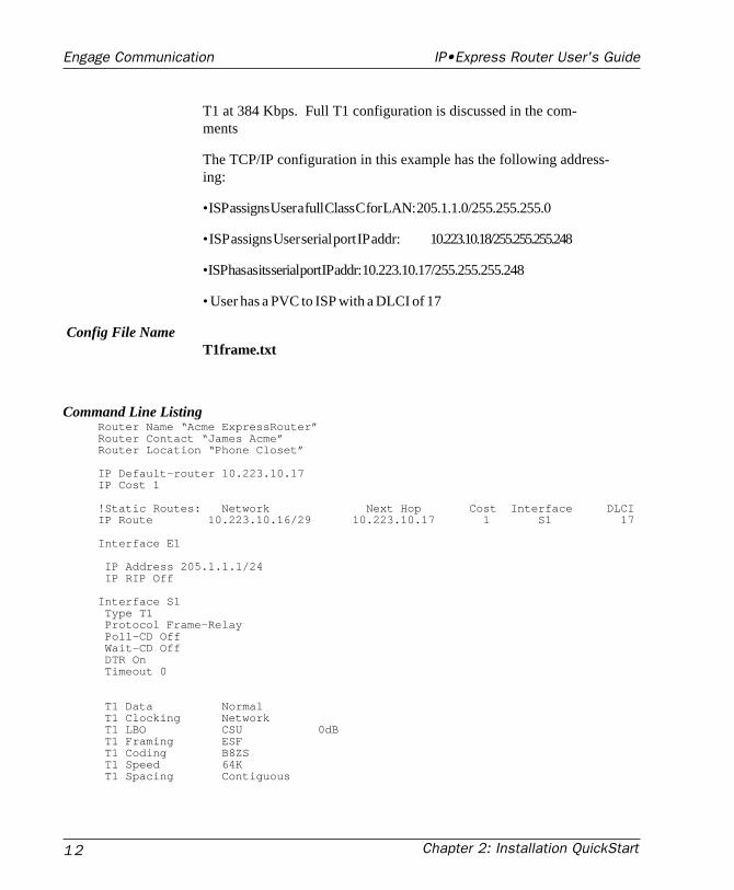
Example 1: T1/fracT1 overFrame Relay to an ISP
ScenarioThis sample configuration details an Engage Router connection to anInternet Service Provider (ISP) over Frame Relay. The hardware in thisexample is the IP•Express with internal T1 DSU/CSU running fractional
Chapter 2: Installation QuickStart12
Engage Communication IP•Express Router User's Guide
T1 at 384 Kbps. Full T1 configuration is discussed in the com-ments
The TCP/IP configuration in this example has the following address-ing:
• ISP assigns User a full Class C for LAN: 205.1.1.0/255.255.255.0
• ISP assigns User serial port IP addr: 10.223.10.18/255.255.255.248
• ISP has as its serial port IP addr: 10.223.10.17/255.255.255.248
• User has a PVC to ISP with a DLCI of 17
Config File NameT1frame.txt
Command Line ListingRouter Name “Acme ExpressRouter”Router Contact “James Acme”Router Location “Phone Closet”
IP Default-router 10.223.10.17IP Cost 1
!Static Routes: Network Next Hop Cost Interface DLCIIP Route 10.223.10.16/29 10.223.10.17 1 S1 17
Interface E1
IP Address 205.1.1.1/24 IP RIP Off
Interface S1 Type T1 Protocol Frame-Relay Poll-CD Off Wait-CD Off DTR On Timeout 0
T1 Data Normal T1 Clocking Network T1 LBO CSU 0dB T1 Framing ESF T1 Coding B8ZS T1 Speed 64K T1 Spacing Contiguous
Chapter 2: Installation QuickStart 13
Engage Communication IP•Express Router User's Guide
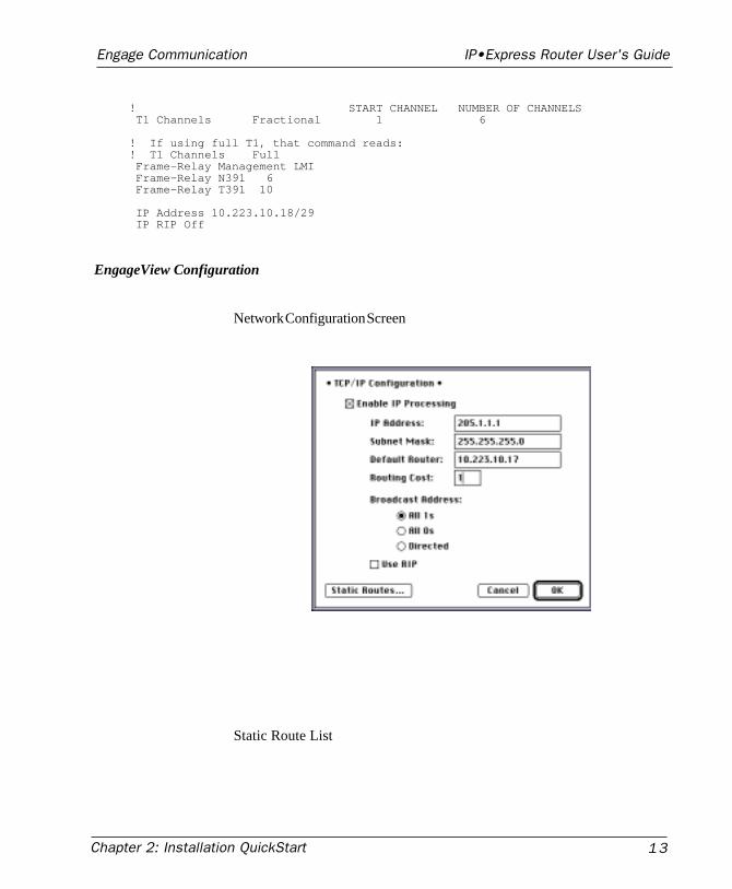
! START CHANNEL NUMBER OF CHANNELS T1 Channels Fractional 1 6
! If using full T1, that command reads:! T1 Channels Full Frame-Relay Management LMI Frame-Relay N391 6 Frame-Relay T391 10
IP Address 10.223.10.18/29 IP RIP Off
EngageView Configuration
Network Configuration Screen
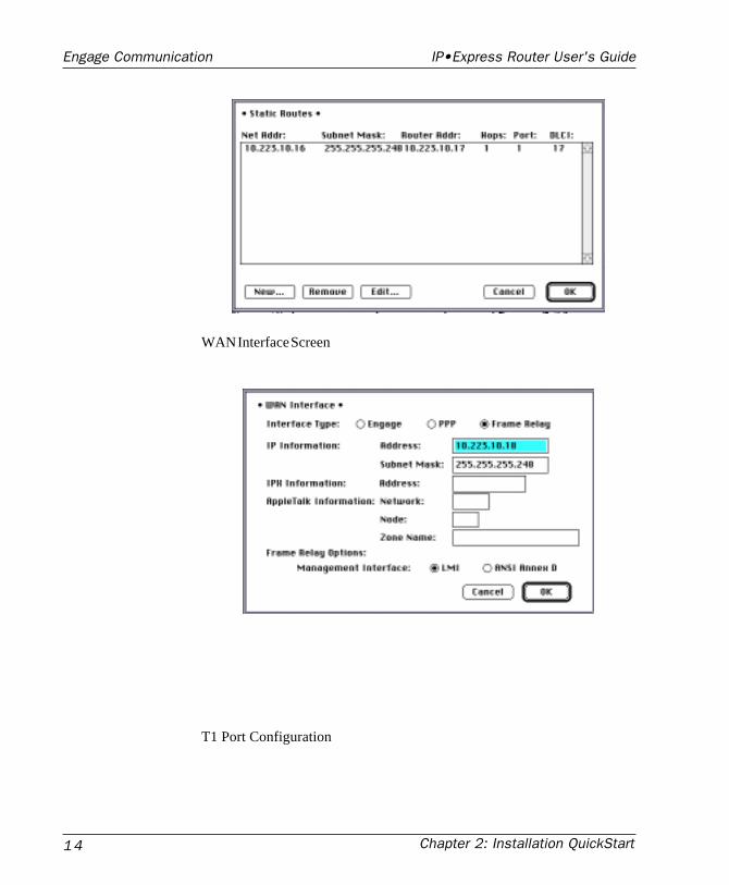
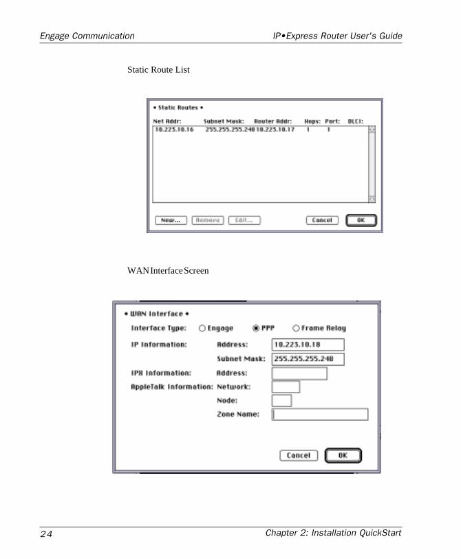
Static Route List
Chapter 2: Installation QuickStart14
Engage Communication IP•Express Router User's Guide
WAN Interface Screen
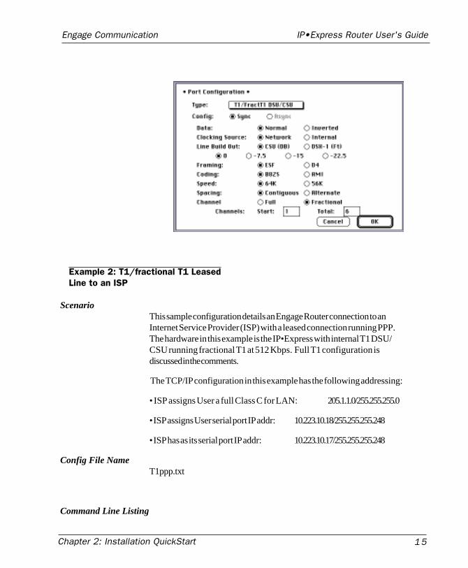
T1 Port Configuration
Chapter 2: Installation QuickStart 15
Engage Communication IP•Express Router User's Guide
Example 2: T1/fractional T1 LeasedLine to an ISP
ScenarioThis sample configuration details an Engage Router connection to anInternet Service Provider (ISP) with a leased connection running PPP.The hardware in this example is the IP•Express with internal T1 DSU/CSU running fractional T1 at 512 Kbps. Full T1 configuration isdiscussed in the comments.
The TCP/IP configuration in this example has the following addressing:
• ISP assigns User a full Class C for LAN: 205.1.1.0/255.255.255.0
• ISP assigns User serial port IP addr: 10.223.10.18/255.255.255.248
• ISP has as its serial port IP addr: 10.223.10.17/255.255.255.248
Config File NameT1ppp.txt
Command Line Listing
Chapter 2: Installation QuickStart16
Engage Communication IP•Express Router User's Guide
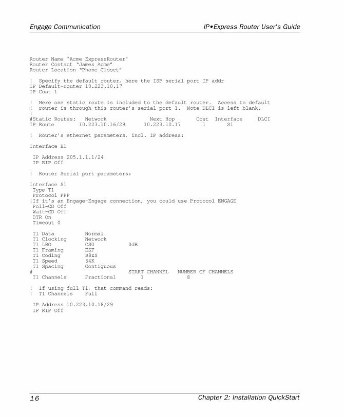
Router Name “Acme ExpressRouter”Router Contact “James Acme”Router Location “Phone Closet”
! Specify the default router, here the ISP serial port IP addrIP Default-router 10.223.10.17IP Cost 1
! Here one static route is included to the default router. Access to default! router is through this router’s serial port 1. Note DLCI is left blank.!#Static Routes: Network Next Hop Cost Interface DLCIIP Route 10.223.10.16/29 10.223.10.17 1 S1
! Router’s ethernet parameters, incl. IP address:
Interface E1
IP Address 205.1.1.1/24 IP RIP Off
! Router Serial port parameters:
Interface S1 Type T1 Protocol PPP!If it’s an Engage-Engage connection, you could use Protocol ENGAGE Poll-CD Off Wait-CD Off DTR On Timeout 0
T1 Data Normal T1 Clocking Network T1 LBO CSU 0dB T1 Framing ESF T1 Coding B8ZS T1 Speed 64K T1 Spacing Contiguous# START CHANNEL NUMBER OF CHANNELS T1 Channels Fractional 1 8
! If using full T1, that command reads:! T1 Channels Full
IP Address 10.223.10.18/29 IP RIP Off
Chapter 2: Installation QuickStart 17
Engage Communication IP•Express Router User's Guide
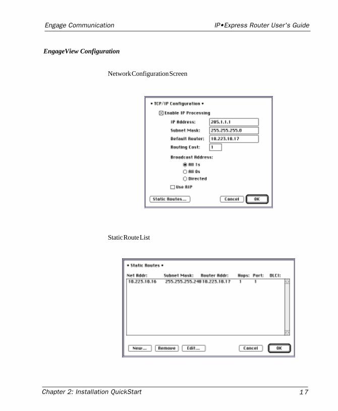
EngageView Configuration
Network Configuration Screen
Static Route List
Chapter 2: Installation QuickStart18
Engage Communication IP•Express Router User's Guide
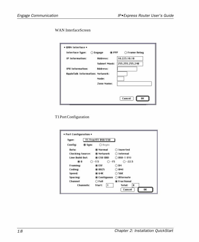
WAN InterfaceScreen
T1 Port Configuration
Chapter 2: Installation QuickStart 19
Engage Communication IP•Express Router User's Guide
Example 3: 56Kbps Frame Relay toan ISP
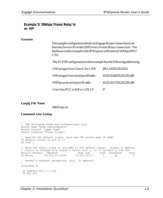
ScenarioThis sample configuration details an Engage Router connection to anInternet Service Provider (ISP) over a Frame Relay connection. Thehardware in this example is the IP•Express with internal 56 Kbps DSU/CSU.
The TCP/IP configuration in this example has the following addressing:
• ISP assigns User Class C for LAN: 205.1.1.0/255.255.255.0
• ISP assigns User serial port IP addr: 10.223.10.18/255.255.255.248
• ISP has as its serial port IP addr: 10.223.10.17/255.255.255.248
• User has PVC to ISP w/ a DLCI: 17
Config File Name56KFram.txt
Command Line Listing
! The following items are informational onlyRouter Name “Acme ExpressRouter”Router Contact “James Acme”Router Location “Phone Closet”
! Specify the default router, here the ISP serial port IP addrIP Default-router 10.223.10.17IP Cost 1
! Here one static route is included to the default router. Access to default! router is through this router’s serial port 1, w/ 17 as DLCI to the ISP#Static Routes: Network Next Hop Cost Interface DLCIIP Route 10.223.10.16/29 10.223.10.17 1 S1 17
! Router’s ethernet parameters, incl. IP address:
Interface E1
IP Address 205.1.1.1/24 IP RIP Off
Chapter 2: Installation QuickStart20
Engage Communication IP•Express Router User's Guide
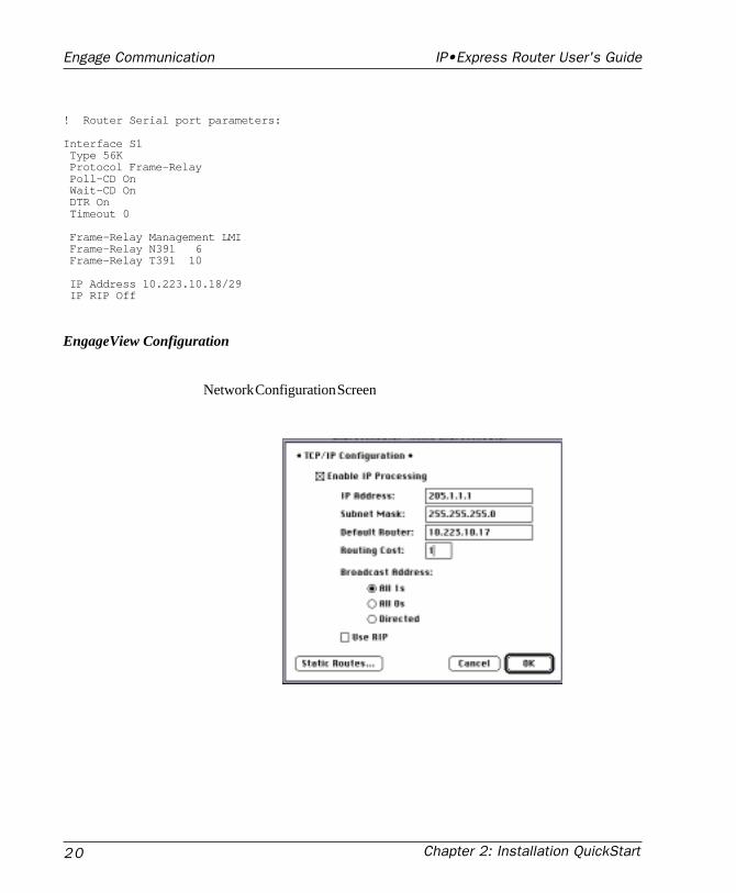
! Router Serial port parameters:
Interface S1 Type 56K Protocol Frame-Relay Poll-CD On Wait-CD On DTR On Timeout 0
Frame-Relay Management LMI Frame-Relay N391 6 Frame-Relay T391 10
IP Address 10.223.10.18/29 IP RIP Off
EngageView Configuration
Network Configuration Screen
Chapter 2: Installation QuickStart 21
Engage Communication IP•Express Router User's Guide
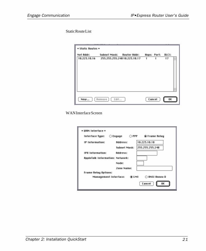
Static Route List
WAN Interface Screen
Chapter 2: Installation QuickStart22
Engage Communication IP•Express Router User's Guide
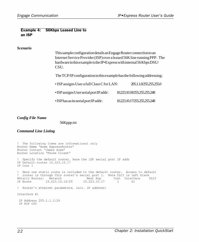
Example 4: 56Kbps Leased Line toan ISP
ScenarioThis sample configuration details an Engage Router connection to anInternet Service Provider (ISP) over a leased 56K line running PPP. Thehardware in this example is the IP•Express with internal 56 Kbps DSU/CSU.
The TCP/IP configuration in this example has the following addressing:
• ISP assigns User a full Class C for LAN: 205.1.1.0/255.255.255.0
• ISP assigns User serial port IP addr: 10.223.10.18/255.255.255.248
• ISP has as its serial port IP addr: 10.223.10.17/255.255.255.248
Config File Name56Kppp.txt
Command Line Listing
! The following items are informational onlyRouter Name “Acme ExpressRouter”Router Contact “James Acme”Router Location “Phone Closet”
! Specify the default router, here the ISP serial port IP addrIP Default-router 10.223.10.17IP Cost 1
! Here one static route is included to the default router. Access to default! router is through this router’s serial port 1. Note DLCI is left blank#Static Routes: Network Next Hop Cost Interface DLCIIP Route 10.223.10.16/29 10.223.10.17 1 S1
! Router’s ethernet parameters, incl. IP address:
Interface E1
IP Address 205.1.1.1/24 IP RIP Off
Chapter 2: Installation QuickStart 23
Engage Communication IP•Express Router User's Guide
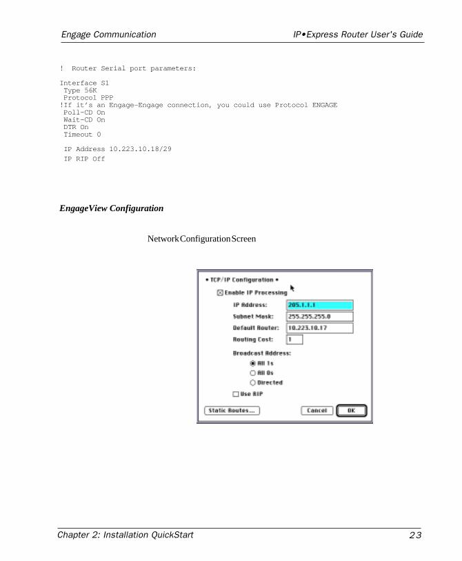
! Router Serial port parameters:
Interface S1 Type 56K Protocol PPP!If it’s an Engage-Engage connection, you could use Protocol ENGAGE Poll-CD On Wait-CD On DTR On Timeout 0
IP Address 10.223.10.18/29
IP RIP Off
EngageView Configuration
Network Configuration Screen
Chapter 2: Installation QuickStart24
Engage Communication IP•Express Router User's Guide
Static Route List
WAN Interface Screen
Chapter 2: Installation QuickStart 25
Engage Communication IP•Express Router User's Guide
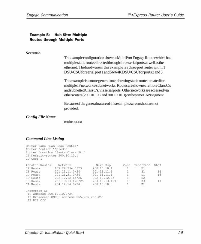
Example 5: Hub Site: MultipleRoutes through Multiple Ports
ScenarioThis sample configuration shows a MultiPort Engage Router which hasmultiple static routes directed through three serial ports as well as theethernet. The hardware in this example is a three port router with T1DSU/CSU for serial port 1 and 56/64K DSU/CSU for ports 2 and 3.
This example is a more general one, showing static routes created formultiple IP networks/subnetworks. Routes are shown to remote Class C'sand subnetted Class C's, via serial ports. Other networks are accessed viaother routers (200.10.10.2 and 200.10.10.3) on the same LAN segment.
Because of the general nature of this example, screen shots are notprovided.
Config File Namemultrout.txt
Command Line Listing
Router Name "San Jose Router"Router Contact "Spiedo"Router Location "Santa Clara St."IP Default-router 200.10.10.1IP Cost 1
#Static Routes: Network Next Hop Cost Interface DLCIIP Route 157.22.234.0/23 200.10.10.1 1 E1IP Route 201.11.11.0/24 201.11.11.1 1 S1 16IP Route 201.21.21.0/24 201.11.11.1 1 S1 16IP Route 202.12.12.64/26 202.12.12.65 1 S2IP Route 203.13.13.128/25 203.13.13.129 1 S3 17IP Route 204.14.14.0/24 200.10.10.3 1 E1
Interface E1 IP Address 200.10.10.2/24 IP Broadcast ONES, address 255.255.255.255 IP RIP Off
Chapter 2: Installation QuickStart26
Engage Communication IP•Express Router User's Guide
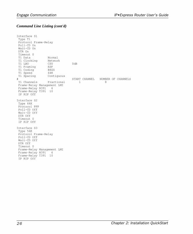
Command Line Listing (cont'd)
Interface S1 Type T1 Protocol Frame-Relay Poll-CD On Wait-CD On DTR On Timeout 0 T1 Data Normal T1 Clocking Network T1 LBO CSU 0dB T1 Framing ESF T1 Coding B8ZS T1 Speed 64K T1 Spacing Contiguous# START CHANNEL NUMBER OF CHANNELS T1 Channels Fractional 1 8 Frame-Relay Management LMI Frame-Relay N391 6 Frame-Relay T391 10 IP RIP Off
Interface S2 Type 64K Protocol PPP Poll-CD Off Wait-CD Off DTR Off Timeout 0 IP RIP Off
Interface S3 Type 56K Protocol Frame-Relay Poll-CD Off Wait-CD Off DTR Off Timeout 0 Frame-Relay Management LMI Frame-Relay N391 6 Frame-Relay T391 10 IP RIP Off
Chapter 3: Network Planning 27
Engage Communication IP•Express Router User's Guide
Chapter 3:Network Planning

Chapter 3: Network Planning28
Engage Communication IP•Express Router User's Guide
Chapter 3: Network Planning 29
Engage Communication IP•Express Router User's Guide
Chapter 3
Network Planning
This chapter provides information about network planning for TCP/IPnetworks.
The primary rules for internets are:
1. the IP network address for every physical network must be unique;
2. the IP host address of devices within a net/subnet must be unique.
TCP/IP Networks
TCP/IP AddressingEvery host on a TCP/IP network must be assigned a unique IP address.An IP address is a 32 bit binary value. When writing an IP address, eachbyte of the address is converted into a decimal number and the numbersare separated by dots. e.g. 148.92.127.5
The IP address contains both the network address (Net ID) and the localaddress (Host ID). To determine which portion of the IP address is theNet ID and which portion is the Host ID another 32 bit value, the subnetmask, is required. The subnet mask is written in the same four bytefashion as the IP address. e.g. 255.255.255.0.
The Net ID is a unique identifier for the network to which the Host isattached - it must not conflict with any other Net ID on the internet. TheHost ID is a unique identifier for the device on that network - it must notconflict with any other Host ID on that physical network.
The IP address is assigned by InterNIC, the Internet Network Information
Chapter 3: Network Planning30
Engage Communication IP•Express Router User's Guide
Center, so that there is no duplication within companies on theInternet. Although the network may only be an internal one, it mayhave external communications in the future, so it is best to get anaddress assigned to you by the governing body to avoid majordifficulties later.
There are three formats of internet addresses defined for small(Class C), medium (Class B) and large (Class A) networks.
For Class A addresses, InterNIC assigns a fixed value for the firstbyte address (in the range of 0 to 127) and the last three bytes aremanaged by the organization. The address space for a Class Anetwork is 16,777,216 host addresses.
For Class B addresses, the first two bytes are assigned (startingwith a number in the range of 128 to 191), with the last two bytesmanaged by the organization. Therefore, there are 65,636 hostaddresses for a Class B network.
Class C addresses are given a fixed value for the first three bytesof the address, with the organization managing the last byte. AClass C network has a range of 256 addresses.
Class A and Class B networks make use of their ability to namebytes by breaking their networks into subnets, reflected in theaddress. Subnet addressing is often done at a byte boundary, soin a Class B address, the third byte would reflect the subnetworkand the fourth byte would identify individual hosts.
A Class C network could also address its subnetworks, using oneportion of the fourth byte for the subnet address and the remainingportion for the individual host address.
Chapter 4: Engage Router Hardware 31
Engage Communication IP•Express Router User's Guide
Chapter 4:Engage Router
Har dwar e

Chapter 4: Engage Router Hardware32
Engage Communication IP•Express Router User's Guide
Chapter 4: Engage Router Hardware 33
Engage Communication IP•Express Router User's Guide
Chapter 4
Engage Router Hardware
Engage routers are configured with one Ethernet interface and up to threewide area interfaces. Engage routers are fully interoperable with non-Engage routers through the use of Point-to-Point (PPP) and Frame Relaywide area protocols.
This chapter describes the Engage router hardware. A second generationof the IP•Express, the Advanced Router version, was introduced whichsupplies greater functionality. Advanced Engage Routers are identifiedby the presence of a Console Port on the rear panel.
The XL router line varies in supplying only a 10BaseT ethernet port andoffering a single WAN interface.
Ethernet Interface
Engage routers (other than XL models) provide a Twisted Pair (10BaseT)and a ThinNet (10Base2) interface. Only one of the interfaces can beactive.
Advanced Engage router models, those with a Console port on the rearpanel, have Auto-Sensing ethernet ports. Models which do not have aConsole port require the user to set motherboard DIP Switch 1 as:
DIP Sw1 Setting Active InterfaceON (default) Twisted Pair (10BaseT)OFF ThinNet (10Base2)
The ThinNet interface utilizes a BNC connector to connect to RG-58 (orother 50 ohm) coaxial cabling.
Chapter 4: Engage Router Hardware34
Engage Communication IP•Express Router User's Guide
The Twisted Pair interface utilizes an RJ48 modular connector for usewith the twisted pair cable commonly used in office telephone wiring.
Ethernet Hardware (Physical) Address
On routers with serial number 9000 and greater, the ethernet hardwareaddress may be determined from the unit serial number as:
00:c0:f7:00:wx:yz where wxyz is the unit serial number.
For example, a router with serial number 9025 has ethernet hardwareaddress:
00:c0:f7:00:90:25
Serial Port Interfaces
Engage routers (except XL models) may be configured with up to threeserial ports for Wide Area Network (WAN) connections.
The built-in db25 interfaces can be configured for the following electricalinterfaces (even if an internal DSU/CSU is installed).
• RS-232
• RS-530
• RS-449
• V.35
On earlier models, DTE-3 is a mini-DIN8 port and can be configured foruse with RS232, RS449 or RS530 cabling through the EngageView PortConfiguration selection of the Port menu.
To change the Serial Port Configuration of a db25 port:
1) Open the unit by removing one screw on the top of the rear panel andslide the cover forward.
2) Set the serial port to the desired configuration by changing the Jumper
Chapter 4: Engage Router Hardware 35
Engage Communication IP•Express Router User's Guide
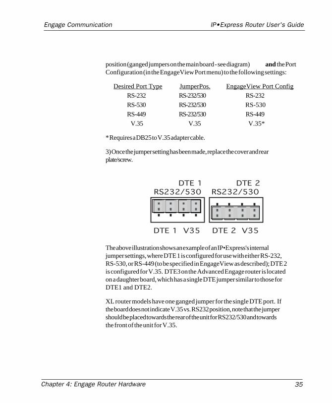
position (ganged jumpers on the main board - see diagram) and the PortConfiguration (in the EngageView Port menu) to the following settings:
Desired Port Type JumperPos. EngageView Port Config
RS-232 RS-232/530 RS-232
RS-530 RS-232/530 RS-530
RS-449 RS-232/530 RS-449
V.35 V.35 V.35*
* Requires a DB25 to V.35 adapter cable.
3) Once the jumper setting has been made, replace the cover and rearplate/screw.
DTE 1 V35 DTE 2 V35
DTE 1RS232/530
DTE 2RS232/530
The above illustration shows an example of an IP•Express's internaljumper settings, where DTE 1 is configured for use with either RS-232,RS-530, or RS-449 (to be specified in EngageView as described); DTE 2is configured for V.35. DTE3 on the Advanced Engage router is locatedon a daughter board, which has a single DTE jumper similar to those forDTE1 and DTE2.
XL router models have one ganged jumper for the single DTE port. Ifthe board does not indicate V.35 vs. RS232 position, note that the jumpershould be placed towards the rear of the unit for RS232/530 and towardsthe front of the unit for V.35.
Chapter 4: Engage Router Hardware36
Engage Communication IP•Express Router User's Guide
Interface LEDs
Front panel LEDs provide status on the Ethernet and serial WAN ports.The Power LED is normally green, although at startup it briefly turnsamber as internal memory devices are loaded.
The Ethernet LED flashes green each time a packet is transmitted out theEthernet port.
The Port LEDs have three states. If no valid data is received on theactive port, the interface LED displays a solid red. If the Engage Routerdetects reception of its own serial link HELLO packet, such as occurs in aloopback condition, the LED turns amber.
When the Engage Router receives HELLO packets from a remote routerthe interface LED turns green and remains green as long as a remotepacket is received every 30 seconds. If remote packets are interrupted formore than 30 seconds, the LED returns to red.
Internal DIP Switches.
Standard/Advanced ModelsStandard router models, those which do not have a rear panel Consoleport, and Advanced router models, those with a db9 Console port, utilizethe following DIP Switches:
Sw 1 - ON for 10BaseT, OFF for Thinnet. Factory Setting is 10BaseT.Note: Advanced router models have auto-sensing ethernet port.
Sw 4 - Clears any IP filters which have been configured for the Engagerouter. When the router is reset or powered up with this switch set to theON position, all filters will be cleared.
Sw 6 - In the ON position, the router will use IEEE 802.3 Ethernet formatfor IP broadcasts. When in the OFF position the router will use DIXEthernet format. Factory Setting is OFF. Switch 6 has no effect on IPXethernet frame type, which is set in EngageView.
Sw 7 - Turn to ON position to force router to its factory default settings.The primary effect is that any downloaded upgrade will be erased.
Chapter 4: Engage Router Hardware 37
Engage Communication IP•Express Router User's Guide
XL Router ModelsSw 1 -Turn to ON position to force router to its factory default settings.The primary effect is that any downloaded upgrade will be erased.
Sw 3 - In the ON position, the router will use IEEE 802.3 Ethernet formatfor IP broadcasts. When in the OFF position the router will use DIXEthernet format. Factory Setting is OFF.
Sw 4 - Clears any IP filters which have been configured for the Engagerouter. When the router is reset or powered up with this switch set to theON position, all filters will be cleared.
Console Port
Advanced and XL router models include a Console port for configuringthe router. The Console port may be used to communicate with the routerlocally through a terminal, or remotely by dialing in through a modem.
The Console port is configured as a DTE (data terminal equipment) port.This allows direct connection to a DCE (data communication equipment)device such as a modem. For connection to other DTE, such as aterminal or PC, a Null Modem adapter is required.
On Advanced router models, the Console port is a female, 9 pin submin-iature “D” connector. A 9pin male/25 pin female adapter is provided foruse with standard 25 pin cabling. Additionally,a 25 pin female/25 pinmale null modem adapter is provided for direct connection to anotherDTE device.
XL router models uitlized an RJ45 jack for the Console port. An RJ45/db25 adapter is provided with the router which, in addition to providing aphysical interface, performs the null modem operation permitting directconnection to other DTE equipment, such as a PC.
The Console port utilizes the command line interface. Telnet/Consoleport commands are detailed in Chapter 7: Command Line Interface.Communication to the console port should be set as:
9600 baud, 1 stop bit, no parity, 8 bit fixed
Pinouts for the Console port, as well as Engage supplied adapters, areprovided in the Appendices.
Chapter 4: Engage Router Hardware38
Engage Communication IP•Express Router User's Guide
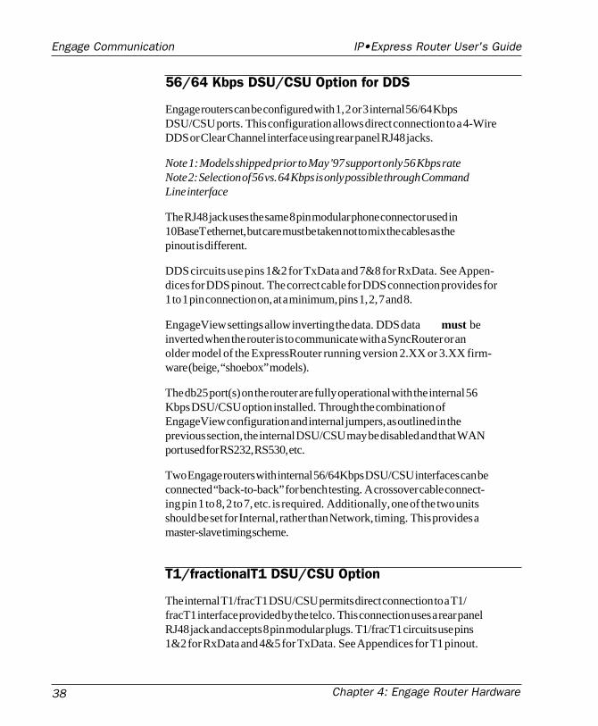
56/64 Kbps DSU/CSU Option for DDS
Engage routers can be configured with 1, 2 or 3 internal 56/64 KbpsDSU/CSU ports. This configuration allows direct connection to a 4-WireDDS or Clear Channel interface using rear panel RJ48 jacks.
Note 1: Models shipped prior to May '97 support only 56 Kbps rateNote 2: Selection of 56 vs. 64 Kbps is only possible through CommandLine interface
The RJ48 jack uses the same 8 pin modular phone connector used in10BaseT ethernet, but care must be taken not to mix the cables as thepinout is different.
DDS circuits use pins 1&2 for TxData and 7&8 for RxData. See Appen-dices for DDS pinout. The correct cable for DDS connection provides for1 to 1 pin connection on, at a minimum, pins 1, 2, 7 and 8.
EngageView settings allow inverting the data. DDS data must beinverted when the router is to communicate with a SyncRouter or anolder model of the ExpressRouter running version 2.XX or 3.XX firm-ware (beige, “shoebox” models).
The db25 port(s) on the router are fully operational with the internal 56Kbps DSU/CSU option installed. Through the combination ofEngageView configuration and internal jumpers, as outlined in theprevious section, the internal DSU/CSU may be disabled and that WANport used for RS232, RS530, etc.
Two Engage routers with internal 56/64Kbps DSU/CSU interfaces can beconnected “back-to-back” for bench testing. A crossover cable connect-ing pin 1 to 8, 2 to 7, etc. is required. Additionally, one of the two unitsshould be set for Internal, rather than Network, timing. This provides amaster-slave timing scheme.
T1/fractionalT1 DSU/CSU Option
The internal T1/fracT1 DSU/CSU permits direct connection to a T1/fracT1 interface provided by the telco. This connection uses a rear panelRJ48 jack and accepts 8 pin modular plugs. T1/fracT1 circuits use pins1&2 for RxData and 4&5 for TxData. See Appendices for T1 pinout.
Chapter 4: Engage Router Hardware 39
Engage Communication IP•Express Router User's Guide
The T1/fracT1 interface can be set to run at rates from 56Kbps up to fullT1 at 1.544 Mbps.
Note : fracT1 running at 56Kbps is not interoperable with 56Kbps DDSservice.
All configurations items, including Line Coding, Framing and TxDatatiming, are configurable using EngageView or the Command LineInterface. See Chapter 7 for T1 Configuration.
Two Engage routers with internal T1/fracT1 DSU/CSU interfaces can beconnected “back-to-back” for bench testing. A crossover cable isrequired (see Appendices). Additionally, one of the two units should beset for Internal, rather than Network, timing. This provides a master-slave timing scheme.
Note: Always configure the T1 DSU/CSU before connecting to a T1 line,as improperly configured T1 circuitry can result in excessive serialerrors which can impair communication to the router, even over ethernet.
E1/fracE1 DSU/CSU Option
The internal E1/fractional E1 DSU/CSU permits direct connection to aE1/fracE1 interface as provided by the telco. This connection uses a rearpanel RJ48 jack and accepts 8 pin modular plugs. E1/fracE1 circuits usepins 1&2 for RxData and 4&5 for TxData. An RJ48/db15 adapter cableis available if the E1 line is terminated in a 15 pin "D" connector. SeeAppendices for E1 pinout and cable specification.
The E1/fracE1 interface can be set to run at rates from 64Kbps up to fullE1 speed of 2.048 Mbps.
All configurations items, including Line Coding and Clock Source, areconfigurable using EngageView or the Command Line Interface.
Two Engage routers with internal E1/fracE1 DSU/CSU interfaces can beconnected “back-to-back” for bench testing. A crossover cable isrequired (see Appendices). Additionally, one of the two units should beset for Internal, rather than Network, timing. This provides a master-slave timing scheme.

Chapter 4: Engage Router Hardware40
Engage Communication IP•Express Router User's Guide

Chapter 5: Installation 41
Engage Communication IP•Express Router User's Guide
Chapter 5:Installation

Chapter 5: Installation42
Engage Communication IP•Express Router User's Guide
Chapter 5: Installation 43
Engage Communication IP•Express Router User's Guide
Chapter 5
Installation of the Engage Router
This chapter provides an overview of the sequence of steps followed insetting up a wide area connection using Engage routers. References aremade to network planning, Engage router hardware and EngageViewsoftware. These topics are covered in detail in their respective chapters.
Installation Requirements
The use of Engage routers to create a wide area network requires onerouter at each side of a synchronous connection. Any Engage router,whether an ExpressRouter or IP•Express, can be connected to any otherEngage router. Engage routers, with support for Point-to-Point Protocol(PPP) and Frame Relay interoperability standards, can also connect toany other manufacturer's routers which support these WAN protocols.
Configuration of Engage routers is performed by use of EngageViewsoftware or through the command line interface via Telnet or the ConsolePort. Refer to the chapters on EngageView and/or the Command LineInterface for more information on configuration.
A standard IP•Express router package includes:
• One Engage IP•Express router• One or more installed WAN interfaces (V.35, T1 DSU/CSU, etc.)• Console port adapter(s)• RJ45 or other cables for optionally installed WAN interfaces• An appropriate 24 VAC power converter (110 or 220 VAC input)• The Engage software installation diskettes (Windows & Mac)• Engage Router User’s Guide• Owner registration card
Chapter 5: Installation44
Engage Communication IP•Express Router User's Guide
Router Installation Steps
The process of installing an Engage router on the network involves thefollowing steps:
1 Planning for network configuration and security
2. Installing the router software
3. Installing the router hardware
4. Configuring the router for the local area network (LAN)
5. Connecting and configuring the data comm equipment (DCE)
6. Verifying the WAN connection
Planning for Network Configuration & Security
To avoid conflicts with network addressing as well as unauthorizedaccess to sensitive areas of your network, it is advisable to have completenetwork address information available to verify that your new networkaddress(es) are unique. Determine in advance which networks/subnet-works you wish to filter - to block from access by remote network users.
For more information on network planning, please see Chapter 3:Network Planning.
Installing Engage Software for Windows
Engage software for Windows provides executable files which communi-cate to the router using the TCP/IP protocol.
To install, insert the disk and select the IP subdirectory. Run the programsetup.exe in the selected subdirectory and follow installation instructions.
Part of the installation is assigning proper values to an engage.ini file.These values relate to the network addressing of the host workstation onwhich EngageView is run.
Chapter 5: Installation 45
Engage Communication IP•Express Router User's Guide
TCP/IP NetworksFor TCP/IP, the user is prompted to enter the IP address and Subnet maskfor the Windows workstation running EngageView. Standard dotteddecimal notation is used:
eg: 201.45.194.1 or 255.255.255.0
Installing Engage Software for Macintosh
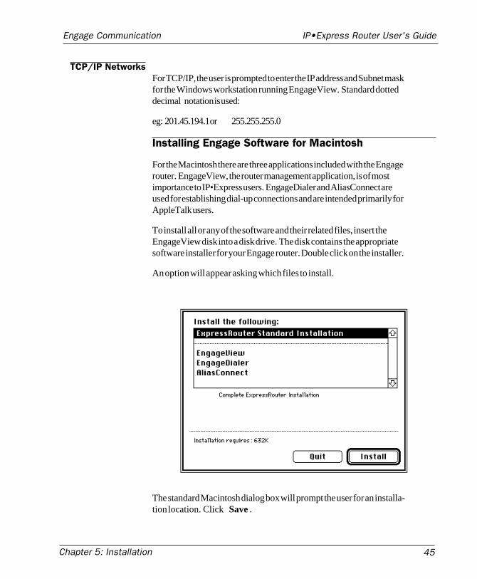
For the Macintosh there are three applications included with the Engagerouter. EngageView, the router management application, is of mostimportance to IP•Express users. EngageDialer and AliasConnect areused for establishing dial-up connections and are intended primarily forAppleTalk users.
To install all or any of the software and their related files, insert theEngageView disk into a disk drive. The disk contains the appropriatesoftware installer for your Engage router. Double click on the installer.
An option will appear asking which files to install.
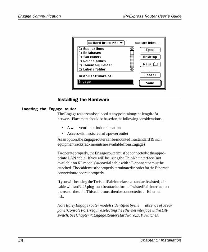
The standard Macintosh dialog box will prompt the user for an installa-tion location. Click Save .
Chapter 5: Installation46
Engage Communication IP•Express Router User's Guide
Installing the Hardware
Locating the Engage routerThe Engage router can be placed at any point along the length of anetwork. Placement should be based on the following considerations:
• A well-ventilated indoor location
• Access within six feet of a power outlet
As an option, the Engage router can be mounted in a standard 19 inchequipment rack (rack mounts are available from Engage)
To operate properly, the Engage router must be connected to the appro-priate LAN cable. If you will be using the ThinNet interface (notavailable on XL models) a coaxial cable with a T-connector must beattached. The cable must be properly terminated in order for the Ethernetconnection to operate properly.
If you will be using the Twisted Pair interface, a standard twisted paircable with an RJ45 plug must be attached to the Twisted Pair interface onthe rear of the unit. This cable must then be connected to an Ethernethub.
Note Early Engage router models (identified by the absence of a rearpanel Console Port) require selecting the ethernet interface with a DIPswitch. See Chapter 4: Engage Router Hardware, DIP Switches.
Chapter 5: Installation 47
Engage Communication IP•Express Router User's Guide
Powering up the RouterIt is recommended that the power adapter be connected to the rear panelPOWER input of the Engage router before connecting to the AC outlet.
After turning on unit power, check the POWER LED on the front panelof the Engage router.
The POWER LED will be GREEN when the internal diagnostics havecompleted successfully. If the internal diagnostics have failed, it isYELLOW. If the power is not connected, the LED will be OFF.
The function of the other LED indicators is detailed in the hardwaredescription of the specific models.
Verifying the Ethernet InterfaceA second indicator, ETHERNET, provides a simple verification of theconnection of the Engage router to its network segment:
• The ETHERNET LED will blink GREEN during normal packettransmission.
• If, after power-on, the Engage router is unable to acquire a uniquenetwork address on the LAN, it will show a steady RED.
• If the ETHERNET LED is a steady GREEN or AMBER, then thenetwork interface is faulty - the Engage router is unable to completea packet transmission.
Configuring the Engage Router for the LAN
The Engage router needs to be configured with a number of parameterswhich determine the router’s operation in the network including:
• IP address and subnet mask
• Default router IP address
• Security options: passwords and/or packet filtering
The configuration procedure depends on the network environment inwhich the Engage router is to be installed.
Chapter 5: Installation48
Engage Communication IP•Express Router User's Guide
Note: It is strongly suggested that you configure your router with itsunique network identity before making any Wide Area Connection.
Initial Communication with the Router in a TCP/IPenvironment
Several methods exist for configuring the IP address of an “unknown”router for use on an IP network. One of these methods must be employedwhen configuring a new router or a router with an unknown address.
The first method consists of communication through the router's Consoleport. The console port utilizes the same command line interface as Telnetand an IP address can be directly assigned. See Chapter 4 for a hardwaredescription and Chapter 7 for Command Line Interface.
The second method is performed by using the Boot Router sequence ofthe EngageView/IP application. The user provides the desired IP addressand subnet mask and a power-on handshake sequence between theEngageRouter and the Windows EngageView/IP application results in therouter adopting the desired IP address. See Chapter 6: EngageView.
A third method employs Telnet to assign an IP address. The router ispowered on and the user immediately initiates a Telnet session to theunused IP address which is intended for the router. The user is thenasked to confirm the IP address which the router has adopted on aprovisional basis. See Chapter 7: Command Line Interface.
A fourth method utilizes the EngageView application on the Macintosh.The IP•Express router will appear as a node on the AppleTalk networkand configuration of all TCP/IP parameters can be performed directly.
Finally, the Engage ExpressRouter will obtain an IP address on power upfrom a local BootP or DHCP server.
Note: Any IP address assignment method (BootRouter, Telnet or DHCP)requires that the router be assigned an IP address which is on the samesubnet as the workstation itself.
Chapter 5: Installation 49
Engage Communication IP•Express Router User's Guide
Connecting and Configuring the DataCommunication Equipment
The Data Communication Equipment (DCE) required is determined bythe type of communication service used for the router connection. Thisincludes DSU/CSU units, ISDN Terminal Adapters, modems andMultiplexers.
This communication equipment is configured to provide a full duplexconnection between the Engage routers. The configuration may be assimple as connecting 56 Kbps DSU/CSUs to a leased line, or as complexas determining how to allocate the desired bandwidth from a Multiplexer.
Many Engage models integrate synchronous communication equipmentinto the Router. Examples include the ExpressRouter DDS, with aninternal 56/64 Kbps DSU/CSU, and the ExpressRouter T1 model, with abuilt-in T1/fracT1 DSU/CSU.
Cabling ConcernsA standard synchronous or asynchronous, male-to-male, one-to-one cableis used to connect the Engage router (the data terminal equipment orDTE) and the telecom equipment (data communication equipment orDCE).
• Male-to-male refers to the connectors at each end of the cable.
• Straight (one-to-one) means that each of the signals of the interfaceused by the Engage router is connected directly from its pin numberat one end of the cable to the same pin number at the other end ofthe cable.
• Synchronous means that the cable has a connection for the transmitdata clocking signal(s), external transmit data clocking signal(s),and receive data clocking signal(s). Asynchronous cables do notutilize the clocking signals.
A simple way to handle the synchronous clocking signal connections is touse cables that interconnect all of the connector pins to the correspondingpins at the other end.
Because synchronous clocking signals are not used by asynchronous links
Chapter 5: Installation50
Engage Communication IP•Express Router User's Guide
there is no guarantee that a cable used in successfully interconnecting adevice to an asynchronous modem will work for synchronous operation.
Telco ConnectionThe connection from the DCE, whether integrated in the Engage router orexternal, to the telephone network is defined by the type of communica-tion service used for the router connection. It may be a simple RJ11cable, as in the case of 2Wire SW56, or a more complex connection to anNT-1 as in the case of an ISDN connection.
Specifics of router modelsEach Engage router model is described in detail in the Hardware Descrip-tion chapters. Included here are brief details relating to installation oncertain of the models.
• IP•Express T1: Ensure that the T1 settings are configured, usingEngageView or Telnet, prior to connection to the T1 line.
Note: Connection to a T1 line with incorrect line coding, number ofchannels, etc. can overload the router with framing errors, makingcommunication with the router over the LAN difficult.
Verifying the WAN Connection
The Engage router’s connection to a remote router can be verified by theactive port interface LEDs. Although the port LEDs are specific to theEngage router model used (and are detailed in the Router Hardwarechapter) they do share common characteristics.
• If, after an initial power-up period, the Engage router does notreceive a HELLO packet from another Engage router on the otherside of the serial interface, the port LED will remain RED.
• When the Engage router receives HELLO packets from the remoteEngage router the port LED turns GREEN, and remains GREEN aslong as a remote packets continue to be received. If none arereceived for a thirty second period, the port LED returns to RED.
• When the Engage router detects reception of its own transmittedHELLO packet, as is the case in a Loopback condition, the LEDwill turn AMBER.

IP•Express Router User's GuideEngage Communication
Chapter 6: EngageView 51
Chapter 6:EngageV iew

52 Chapter 6: EngageView
IP•Express Router User's GuideEngage Communication
IP•Express Router User's GuideEngage Communication
Chapter 6: EngageView 53
Chapter 6
EngageView
EngageView network management software is used to monitor andconfigure any accessible Engage router on the internet. EngageView isavailable for Windows and Macintosh operating systems. Note:EngageView for Windows is Windows95 only!
For information on installing EngageView, see Chapter 5, Installing theEngage Router.
Starting EngageView
The first time EngageView is launched, the program will open with theStatus Window. The Status Window will be blank initially, as the userhas not selected a router.
The first step when using EngageView is to select a router.
If EngageView has been previously launched, it will attempt to connectto the router that was selected the last time EngageView was run. This isbased on previously saved settings.
If no router has been selected or you wish to select a different router,follow the steps outlined below.
54 Chapter 6: EngageView
IP•Express Router User's GuideEngage Communication
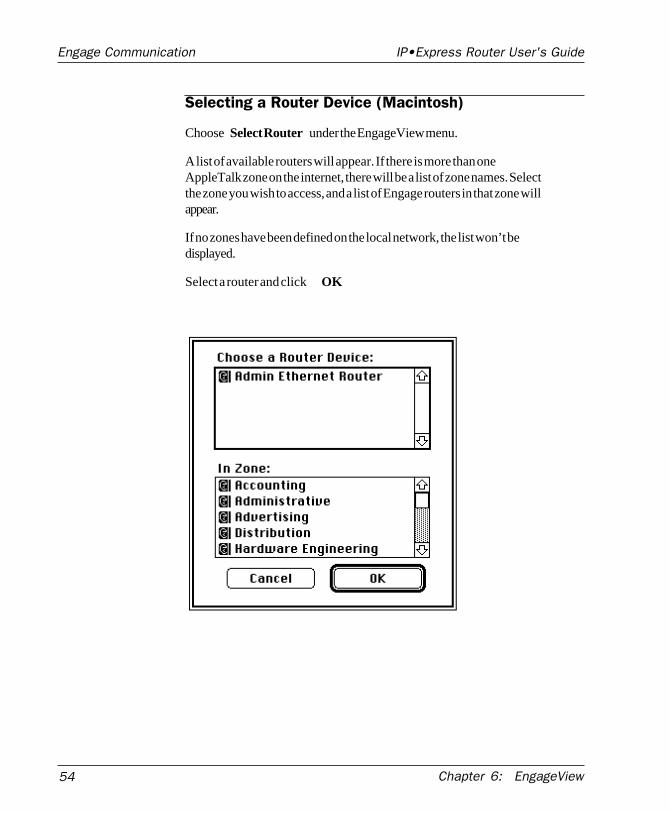
Selecting a Router Device (Macintosh)
Choose Select Router under the EngageView menu.
A list of available routers will appear. If there is more than oneAppleTalk zone on the internet, there will be a list of zone names. Selectthe zone you wish to access, and a list of Engage routers in that zone willappear.
If no zones have been defined on the local network, the list won’t bedisplayed.
Select a router and click OK.
IP•Express Router User's GuideEngage Communication
Chapter 6: EngageView 55
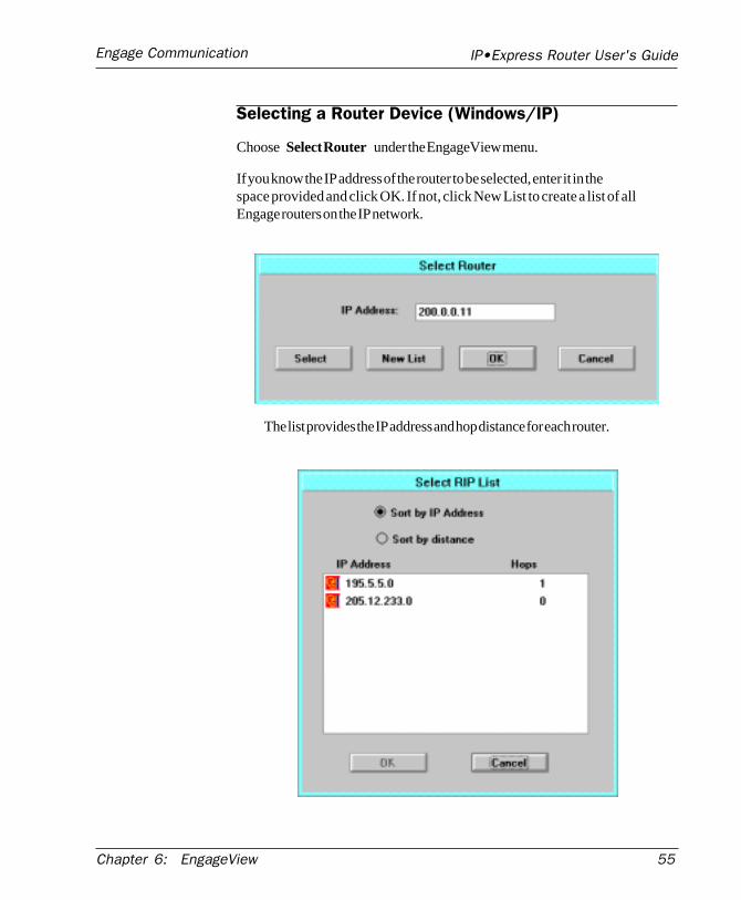
Selecting a Router Device (Windows/IP)
Choose Select Router under the EngageView menu.
If you know the IP address of the router to be selected, enter it in thespace provided and click OK. If not, click New List to create a list of allEngage routers on the IP network.
The list provides the IP address and hop distance for each router.
56 Chapter 6: EngageView
IP•Express Router User's GuideEngage Communication
Select the desired router(s) and click OK. The router(s) will be added tothe router list.
Using EngageView
Now that a router has been selected, EngageView can be used. Central toEngageView's operation are the File, EngageView, Router, and Portmenus.
Note: IP•Express routers support only the TCP/IP protocol suite.EngageView menu items relating to the IPX and AppleTalk LANprotocols are not available to IP•Express users.
The File menu allows the user to open and close the EngageView statuswindow. The EngageView menu allows the user to choose the routerconnection and set preferences. The Router menu allows the user to set arouter name, configure ethernet IP parameters and set an administrativepassword. The Port menu allows the user to change the interface type,configuration and dialing passwords for individual ports.
Configuring Engage routers is done via the EngageView, Router and Portmenus.
This section describes the interface and function of these EngageViewmenus.
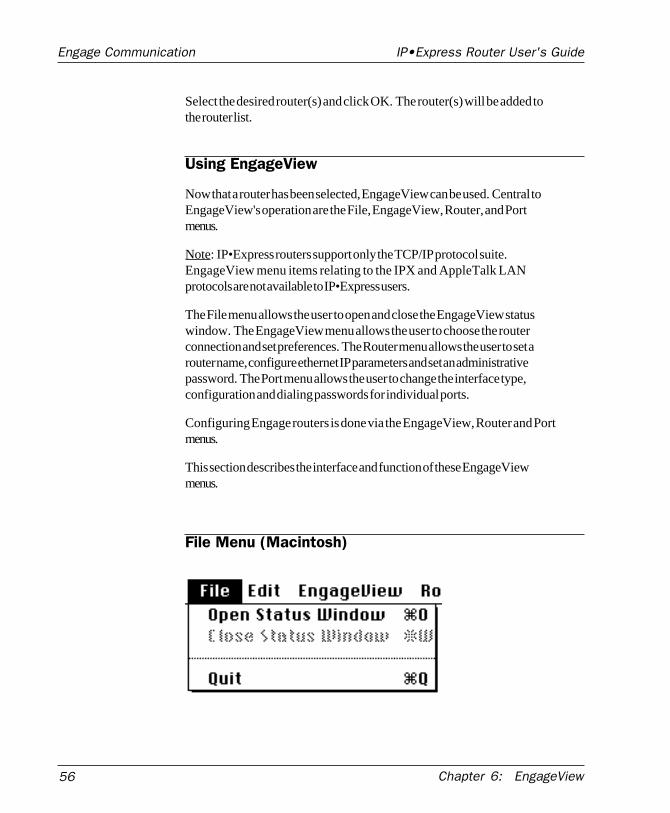
File Menu (Macintosh)
IP•Express Router User's GuideEngage Communication
Chapter 6: EngageView 57
There are three choices under the file menu:
Open Status Window : Will open the Status window. This selection willbe grayed out if the Status Window is already open.
Close Status Window : Will close the Status window. This selection willbe grayed out if the Status Window is already closed.
Quit: Will quit EngageView.
The Status Window is discussed in the next section
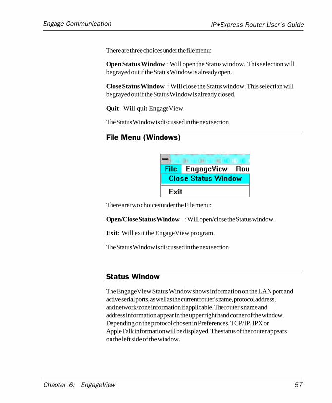
File Menu (Windows)
There are two choices under the File menu:
Open/Close Status Window : Will open/close the Status window.
Exit: Will exit the EngageView program.
The Status Window is discussed in the next section
Status Window
The EngageView Status Window shows information on the LAN port andactive serial ports, as well as the current router's name, protocol address,and network/zone information if applicable. The router's name andaddress information appear in the upper right hand corner of the window.Depending on the protocol chosen in Preferences, TCP/IP, IPX orAppleTalk information will be displayed. The status of the router appearson the left side of the window.
58 Chapter 6: EngageView
IP•Express Router User's GuideEngage Communication
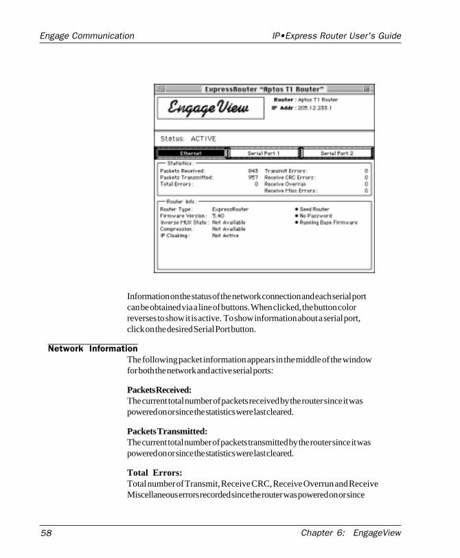
Information on the status of the network connection and each serial portcan be obtained via a line of buttons. When clicked, the button colorreverses to show it is active. To show information about a serial port,click on the desired Serial Port button.
Network InformationThe following packet information appears in the middle of the windowfor both the network and active serial ports:
Packets Received:The current total number of packets received by the router since it waspowered on or since the statistics were last cleared.
Packets Transmitted:The current total number of packets transmitted by the router since it waspowered on or since the statistics were last cleared.
Total Errors:Total number of Transmit, Receive CRC, Receive Overrun and ReceiveMiscellaneous errors recorded since the router was powered on or since
IP•Express Router User's GuideEngage Communication
Chapter 6: EngageView 59
the statistics were last cleared.
Transmit Errors:Number of packet errors recorded since the router began transmitting orsince the statistics were last cleared; these are packets which did notreach the network.
Receive CRC Errors:Number of incoming packets which did not match the Cyclic RedundancyCheck which verifies that data was received correctly.
Receive Overrun Errors:Number of packets received before adequate buffer space was madeavailable.
Receive Misc. Errors:Number of errors on received packets which do not fall into any of theabove categories.
In the bottom section of the window, when the Ethernet button is se-lected, the following information is given:
Router Type:The type of router being monitored.
Firmware Version:The current firmware version running in the router.
Inverse Multiplex State:Shows which ports, if any, have been configured for inverse multiplex-ing. This is only available with the two port ExpressRouter.
Compression:Shows if compression is enabled - available on LocalTalk routers only.
Cloaking:Shows if the router has cloaking, an AppleTalk feature, enabled.
60 Chapter 6: EngageView
IP•Express Router User's GuideEngage Communication
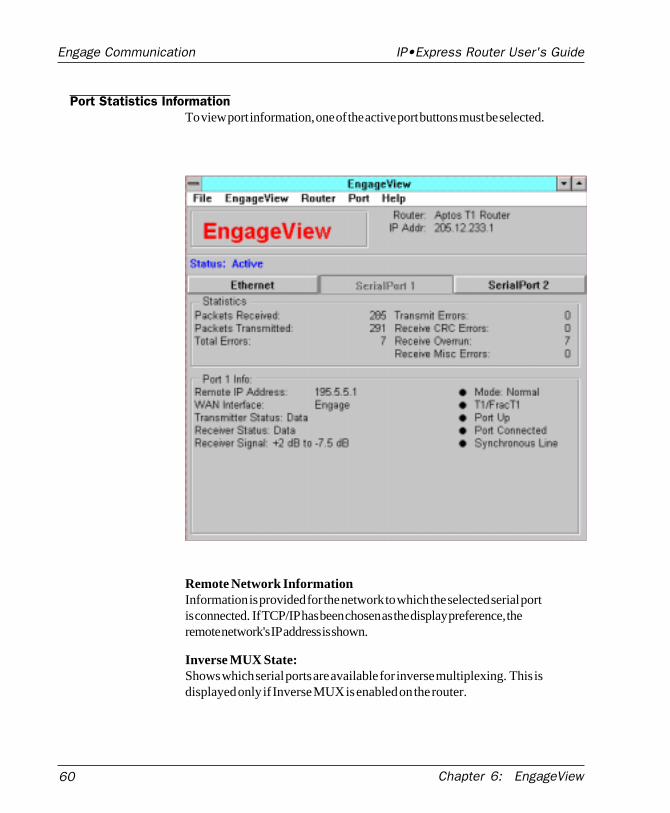
Port Statistics InformationTo view port information, one of the active port buttons must be selected.
Remote Network InformationInformation is provided for the network to which the selected serial portis connected. If TCP/IP has been chosen as the display preference, theremote network's IP address is shown.
Inverse MUX State:Shows which serial ports are available for inverse multiplexing. This isdisplayed only if Inverse MUX is enabled on the router.
IP•Express Router User's GuideEngage Communication
Chapter 6: EngageView 61
Multiplex State:Shows the state of Inverse MUX on this port if Inverse MUX is enabled.This will either be "Waiting" or "Multiplexing."
Mode:The port will be in Normal operating mode when it is routing data. It willbe in Command mode when it is servicing requests from an EngageDialer script for a dial-up connection.
Interface Type (V.35 or other) :This displays the port interface. Types available include V.35, RS232,RS449, 56K DSU/CSU, T1 DSU/CSU and E1 DSU/CSU.
Port Up/No Port Activity:When the port is up, it is an active interface and is transmitting andreceiving data.
Connection:This shows the status of the connection to the remote router. It can be:
Port Not Connected: Not connected to remote routerPort Connected: Connected and exchanging data with remote router
Password required:Indicates that the remote router requires a correct dial-in password beforeconnecting.
Line Type:This indicates whether there is synchronous or asynchronous communica-tion.
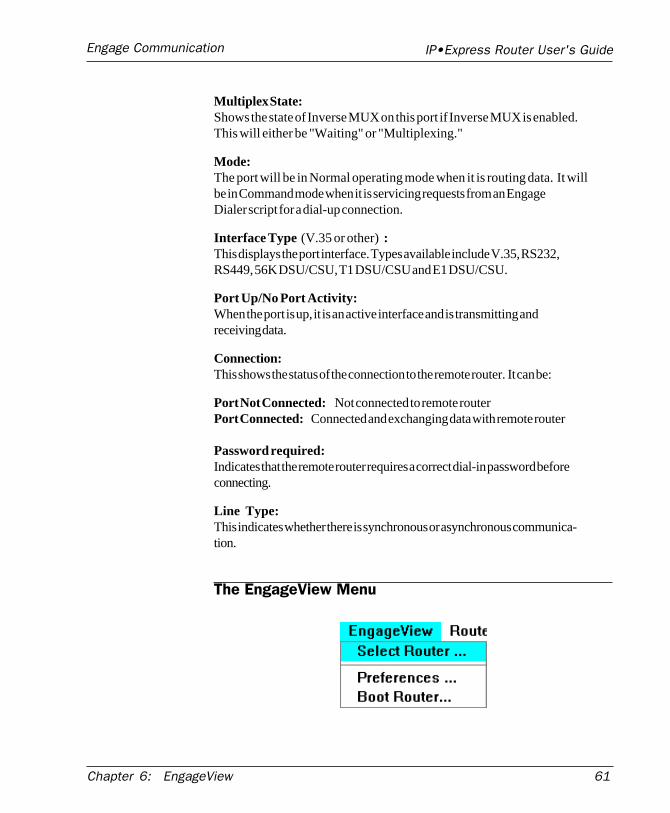
The EngageView Menu
62 Chapter 6: EngageView
IP•Express Router User's GuideEngage Communication
Select Router:To remotely manage routers on the internet, choose Select Router underthe EngageView menu. The sequence for selecting the router variesaccording the platform on which EngageView is run, as detailed in thebeginning of this chapter.
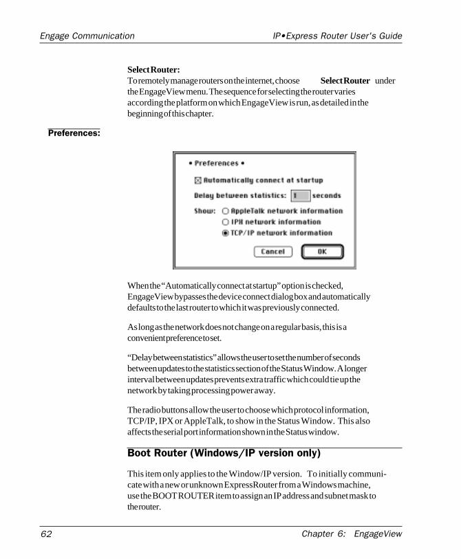
Preferences:
When the “Automatically connect at startup” option is checked,EngageView bypasses the device connect dialog box and automaticallydefaults to the last router to which it was previously connected.
As long as the network does not change on a regular basis, this is aconvenient preference to set.
“Delay between statistics” allows the user to set the number of secondsbetween updates to the statistics section of the Status Window. A longerinterval between updates prevents extra traffic which could tie up thenetwork by taking processing power away.
The radio buttons allow the user to choose which protocol information,TCP/IP, IPX or AppleTalk, to show in the Status Window. This alsoaffects the serial port information shown in the Status window.
Boot Router (Windows/IP version only)
This item only applies to the Window/IP version. To initially communi-cate with a new or unknown ExpressRouter from a Windows machine,use the BOOT ROUTER item to assign an IP address and subnet mask tothe router.
IP•Express Router User's GuideEngage Communication
Chapter 6: EngageView 63
In the BOOT ROUTER item, enter an IP address and subnet mask for theExpressRouter. The ExpressRouter and the host Windows machine must
• be on the same physical network• have IP addresses specifying the same IP network• have the same subnet mask
After entering the IP address and Subnet Mask, click OK. Turn theExpressRouter OFF, then back ON. On powerup, the router will commu-nicate with the Windows machine. The EngageView Boot Routerwindow will close, and the user should be able to connect to the router byproviding the newly assigned IP address in the Select Router menu item.
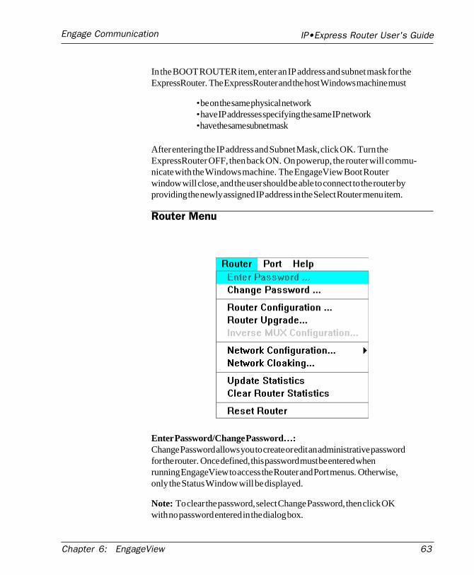
Router Menu
Enter Password/Change Password…:Change Password allows you to create or edit an administrative passwordfor the router. Once defined, this password must be entered whenrunning EngageView to access the Router and Port menus. Otherwise,only the Status Window will be displayed.
Note: To clear the password, select Change Password, then click OKwith no password entered in the dialog box.
64 Chapter 6: EngageView
IP•Express Router User's GuideEngage Communication
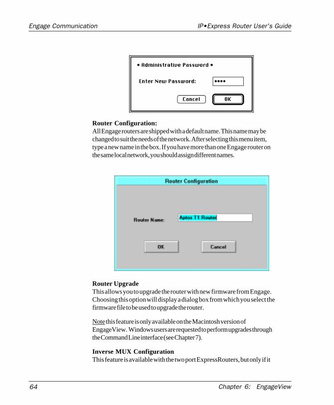
Router Configuration:All Engage routers are shipped with a default name. This name may bechanged to suit the needs of the network. After selecting this menu item,type a new name in the box. If you have more than one Engage router onthe same local network, you should assign different names.
Router UpgradeThis allows you to upgrade the router with new firmware from Engage.Choosing this option will display a dialog box from which you select thefirmware file to be used to upgrade the router.
Note this feature is only available on the Macintosh version ofEngageView. Windows users are requested to perform upgrades throughthe Command Line interface (see Chapter 7).
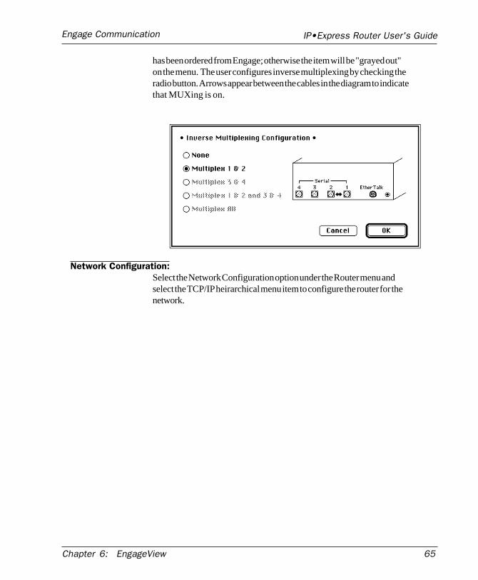
Inverse MUX ConfigurationThis feature is available with the two port ExpressRouters, but only if it
IP•Express Router User's GuideEngage Communication
Chapter 6: EngageView 65
has been ordered from Engage; otherwise the item will be "grayed out"on the menu. The user configures inverse multiplexing by checking theradio button. Arrows appear between the cables in the diagram to indicatethat MUXing is on.
Network Configuration:Select the Network Configuration option under the Router menu andselect the TCP/IP heirarchical menu item to configure the router for thenetwork.
66 Chapter 6: EngageView
IP•Express Router User's GuideEngage Communication
TCP/IP Network:For a TCP/IP network, choose TCP/IP under Network Configuration.
IP Address:An address must be entered to configure the router for IP, and each IPaddress must be unique. EngageView will alert the user if there is aduplicate IP address on the local network, so an alternate address can beentered.
Subnet Mask:This value is dependent upon the class of the IP network the router is onand if subnetting is in effect. A value needs to be entered if the IPnetwork is subnetted.
Default Router:To specify a default router, enter the IP address of the router to be used.Specifying a default router allows the ExpressRouter to forward packets
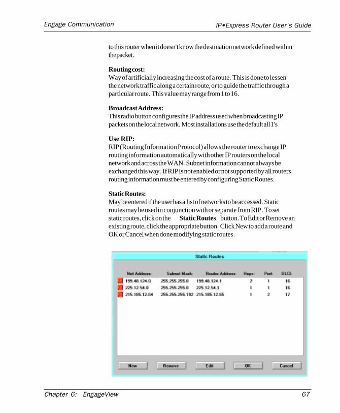
IP•Express Router User's GuideEngage Communication
Chapter 6: EngageView 67
to this router when it doesn't know the destination network defined withinthe packet.
Routing cost:Way of artificially increasing the cost of a route. This is done to lessenthe network traffic along a certain route, or to guide the traffic through aparticular route. This value may range from 1 to 16.
Broadcast Address:This radio button configures the IP address used when broadcasting IPpackets on the local network. Most installations use the default all 1's
Use RIP:RIP (Routing Information Protocol) allows the router to exchange IProuting information automatically with other IP routers on the localnetwork and across the WAN. Subnet information cannot always beexchanged this way. If RIP is not enabled or not supported by all routers,routing information must be entered by configuring Static Routes.
Static Routes:May be entered if the user has a list of networks to be accessed. Staticroutes may be used in conjunction with or separate from RIP. To setstatic routes, click on the Static Routes button. To Edit or Remove anexisting route, click the appropriate button. Click New to add a route andOK or Cancel when done modifying static routes.
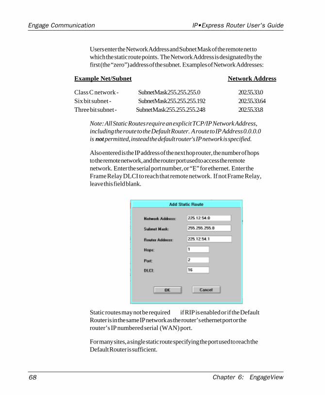
68 Chapter 6: EngageView
IP•Express Router User's GuideEngage Communication
Users enter the Network Address and Subnet Mask of the remote net towhich the static route points. The Network Address is designated by thefirst (the “zero”) address of the subnet. Examples of Network Addresses:
Example Net/Subnet Network Address
Class C network - Subnet Mask 255.255.255.0 202.55.33.0Six bit subnet - Subnet Mask 255.255.255.192 202.55.33.64Three bit subnet - Subnet Mask 255.255.255.248 202.55.33.8
Note: All Static Routes require an explicit TCP/IP Network Address,including the route to the Default Router. A route to IP Address 0.0.0.0is not permitted, instead the default router's IP network is specified.
Also entered is the IP address of the next hop router, the number of hopsto the remote network, and the router port used to access the remotenetwork. Enter the serial port number, or “E” for ethernet. Enter theFrame Relay DLCI to reach that remote network. If not Frame Relay,leave this field blank.
Static routes may not be required if RIP is enabled or if the DefaultRouter is in the same IP network as the router’s ethernet port or therouter’s IP numbered serial (WAN) port.
For many sites, a single static route specifying the port used to reach theDefault Router is sufficient.
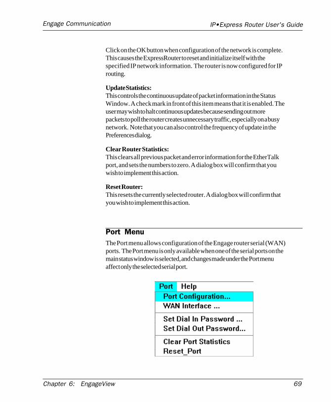
IP•Express Router User's GuideEngage Communication
Chapter 6: EngageView 69
Click on the OK button when configuration of the network is complete.This causes the ExpressRouter to reset and initialize itself with thespecified IP network information. The router is now configured for IProuting.
Update Statistics:This controls the continuous update of packet information in the StatusWindow. A check mark in front of this item means that it is enabled. Theuser may wish to halt continuous updates because sending out morepackets to poll the router creates unnecessary traffic, especially on a busynetwork. Note that you can also control the frequency of update in thePreferences dialog.
Clear Router Statistics:This clears all previous packet and error information for the EtherTalkport, and sets the numbers to zero. A dialog box will confirm that youwish to implement this action.
Reset Router:This resets the currently selected router. A dialog box will confirm thatyou wish to implement this action.
Port MenuThe Port menu allows configuration of the Engage router serial (WAN)ports. The Port menu is only available when one of the serial ports on themain status window is selected, and changes made under the Port menuaffect only the selected serial port.
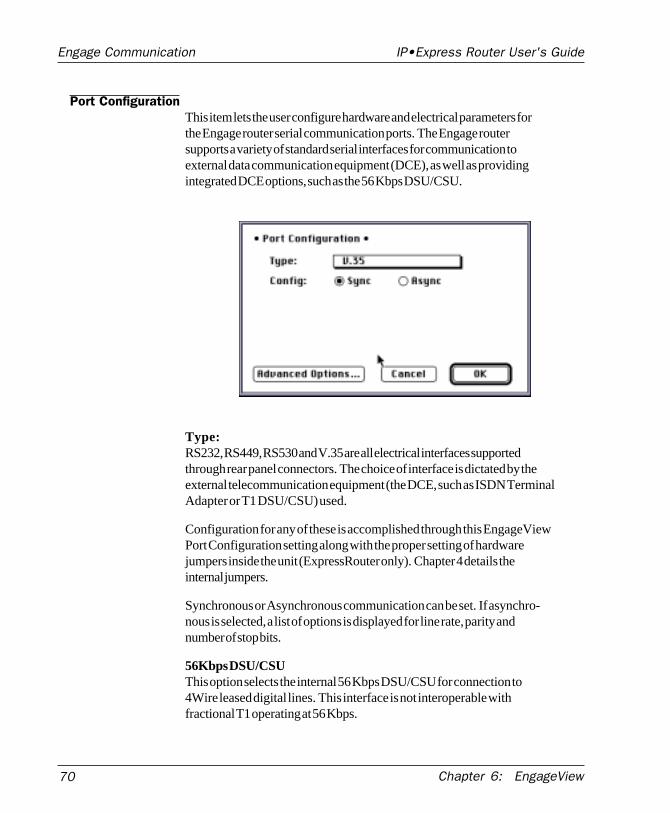
70 Chapter 6: EngageView
IP•Express Router User's GuideEngage Communication
Port ConfigurationThis item lets the user configure hardware and electrical parameters forthe Engage router serial communication ports. The Engage routersupports a variety of standard serial interfaces for communication toexternal data communication equipment (DCE), as well as providingintegrated DCE options, such as the 56 Kbps DSU/CSU.
Type:RS232, RS449, RS530 and V.35 are all electrical interfaces supportedthrough rear panel connectors. The choice of interface is dictated by theexternal telecommunication equipment (the DCE, such as ISDN TerminalAdapter or T1 DSU/CSU) used.
Configuration for any of these is accomplished through this EngageViewPort Configuration setting along with the proper setting of hardwarejumpers inside the unit (ExpressRouter only). Chapter 4 details theinternal jumpers.
Synchronous or Asynchronous communication can be set. If asynchro-nous is selected, a list of options is displayed for line rate, parity andnumber of stop bits.
56Kbps DSU/CSUThis option selects the internal 56 Kbps DSU/CSU for connection to4Wire leased digital lines. This interface is not interoperable withfractional T1 operating at 56 Kbps.
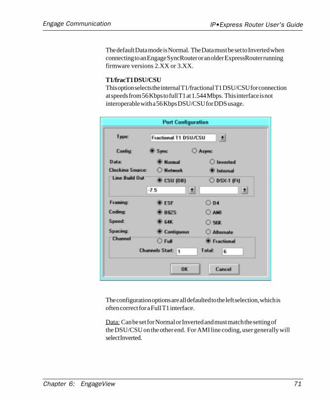
IP•Express Router User's GuideEngage Communication
Chapter 6: EngageView 71
The default Data mode is Normal. The Data must be set to Inverted whenconnecting to an Engage SyncRouter or an older ExpressRouter runningfirmware versions 2.XX or 3.XX.
T1/fracT1 DSU/CSUThis option selects the internal T1/fractional T1 DSU/CSU for connectionat speeds from 56 Kbps to full T1 at 1.544 Mbps. This interface is notinteroperable with a 56 Kbps DSU/CSU for DDS usage.
The configuration options are all defaulted to the left selection, which isoften correct for a Full T1 interface.
Data: Can be set for Normal or Inverted and must match the setting ofthe DSU/CSU on the other end. For AMI line coding, user generally willselect Inverted.
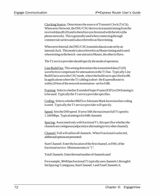
72 Chapter 6: EngageView
IP•Express Router User's GuideEngage Communication
Clocking Source: Determines the source of Transmit Clock (TxCk).When set to Network, the DSU/CSU derives its transmit timing from thereceived data (RxD) and is therefore synchronized with the telco (thephone network). This is generally used when connecting throughcommercial carriers and is also referred to as Slave timing.
When set to Internal, the DSU/CSU transmits data at a rate set by aninternal clock. This mode is also referred to as Master timing and is usedwhen testing on the bench - one unit set to Master, the other to Slave.
The T1 service provider should specify the mode of operation.
Line Build Out: This setting determines the transmitted data (TxD)waveform to compensate for attenuation on the T1 line. Typically LineBuild Out is set to the CSU mode, where the build out is specified in dB.In applications where the T1 cabling is short - the ExpressRouter iswithin 20 feet of the network termination - set for 0 dB.
Framing: Selects whether Extended Super Frame (ESF) or D4 framing isto be used. Typically the T1 service provider specifies.
Coding: Selects whether B8ZS or Alternate Mark Inversion line codingis used. Typically the T1 service provider will specify.
Speed: Sets the DS0 speed. If set to 56K the maximum full T1 speed is1.344 Mbps. Typical setting is for 64K channels
Spacing: Associated only with fractional T1, this specifies whether thechannels are contiguous (adjacent) or alternating (every other channel).
Channel: Full will utilize all channels. When Fractional is selected,additional options are presented:
Start Channel: Enter the location of the first channel, or DS0, of thefractional service. Minimum entry is "1".
Total Channels: Enter the total number of channels used
For example, 384 Kbps fractional T1 typically uses channels 1 through 6.Set Spacing: Contiguous, Start Channel: 1 and Total Channels: 6.
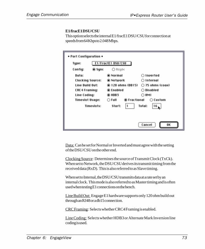
IP•Express Router User's GuideEngage Communication
Chapter 6: EngageView 73
E1/fracE1 DSU/CSUThis option selects the internal E1/fracE1 DSU/CSU for connection atspeeds from 64 Kbps to 2.048 Mbps.
Data: Can be set for Normal or Inverted and must agree with the settingof the DSU/CSU on the other end.
Clocking Source: Determines the source of Transmit Clock (TxCk).When set to Network, the DSU/CSU derives its transmit timing from thereceived data (RxD). This is also referred to as Slave timing.
When set to Internal, the DSU/CSU transmits data at a rate set by aninternal clock. This mode is also referred to as Master timing and is oftenused when testing E1 connections on the bench.
Line Build Out: Engage E1 hardware supports only 120 ohm build outthrough an RJ48 or a db15 connection.
CRC Framing: Selects whether CRC4 Framing is enabled.
Line Coding: Selects whether HDB3 or Alternate Mark Inversion linecoding is used.
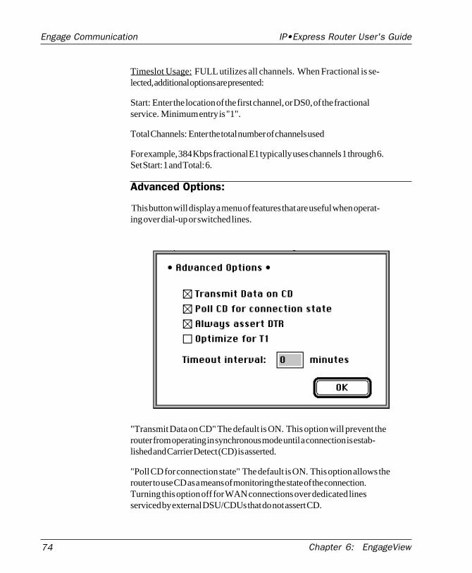
74 Chapter 6: EngageView
IP•Express Router User's GuideEngage Communication
Timeslot Usage: FULL utilizes all channels. When Fractional is se-lected, additional options are presented:
Start: Enter the location of the first channel, or DS0, of the fractionalservice. Minimum entry is "1".
Total Channels: Enter the total number of channels used
For example, 384 Kbps fractional E1 typically uses channels 1 through 6.Set Start: 1 and Total: 6.
Advanced Options:
This button will display a menu of features that are useful when operat-ing over dial-up or switched lines.
"Transmit Data on CD" The default is ON. This option will prevent therouter from operating in synchronous mode until a connection is estab-lished and Carrier Detect (CD) is asserted.
"Poll CD for connection state" The default is ON. This option allows therouter to use CD as a means of monitoring the state of the connection.Turning this option off for WAN connections over dedicated linesserviced by external DSU/CDUs that do not assert CD.
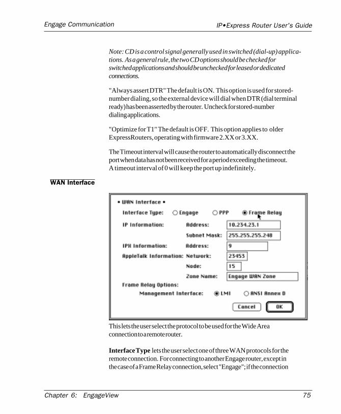
IP•Express Router User's GuideEngage Communication
Chapter 6: EngageView 75
Note: CD is a control signal generally used in switched (dial-up) applica-tions. As a general rule, the two CD options should be checked forswitched applications and should be unchecked for leased or dedicatedconnections.
"Always assert DTR" The default is ON. This option is used for stored-number dialing, so the external device will dial when DTR (dial terminalready) has been asserted by the router. Uncheck for stored-numberdialing applications.
"Optimize for T1" The default is OFF. This option applies to olderExpressRouters, operating with firmware 2.XX or 3.XX.
The Timeout interval will cause the router to automatically disconnect theport when data has not been received for a period exceeding the timeout.A timeout interval of 0 will keep the port up indefinitely.
WAN Interface
This lets the user select the protocol to be used for the Wide Areaconnection to a remote router.
Interface Type lets the user select one of three WAN protocols for theremote connection. For connecting to another Engage router, except inthe case of a Frame Relay connection, select "Engage"; if the connection
76 Chapter 6: EngageView
IP•Express Router User's GuideEngage Communication
is to a non-Engage router, select "PPP" (the non-Engage router must alsosupport PPP protocol). For any connection over a Frame Relay link,select "Frame Relay."
IP Information, IPX Information, AppleTalk InformationThese fields are usually applicable to Frame Relay and PPP connections.Generally, they must be filled out only if the router(s) to which theEngage router connects require a numbered serial interface. Engagerouters are able to operate in either the numbered or the un-numberedmode.
If "Engage" is selected as the WAN Interface Type, there is no need toenter information into these fields. Engage Routers will "learn" thenecessary information automatically.
If the WAN connection requires numbered serial interfaces for any of theprotocols, ensure that the following two conditions are met:
• The network address/number of the serial interface must be unique, itcannot be the same as the network address/number of the ethernetinterface.
For IP, this means the network portion of the IP address, for AppleTalkthis is the network number and for IPX it is the network address.
The WAN connection may be viewed as a virtual network having two ormore nodes - the Engage router’s serial port and the serial port(s) of allother routers connected to the “WAN network”.
• The host portion of the WAN interface must be unique for all nodes onthis virtual network. For IP this means the Host ID portion of the IPaddress and for AppleTalk this is the Node Number.
Generally, if a numbered serial interface is required for the Engagerouter, the network manager in charge of the other routers is responsiblefor defining the virtual WAN network. They will provide networkinformation for the Engage router LAN interface, generally a range ofvalid host/node addresses, and a single address and node for the WANinterface.
Frame Relay OptionsIf the WAN connection is via Frame Relay, the user must select the
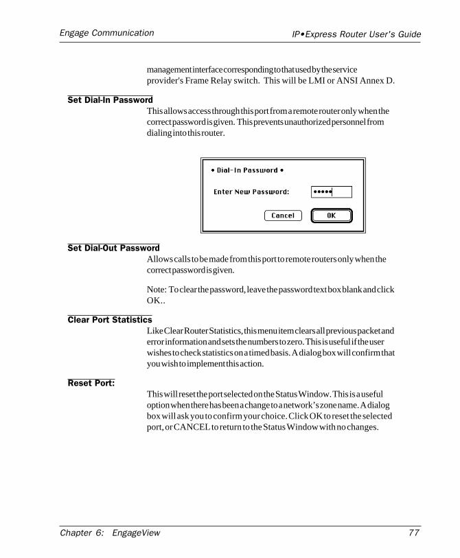
IP•Express Router User's GuideEngage Communication
Chapter 6: EngageView 77
management interface corresponding to that used by the serviceprovider's Frame Relay switch. This will be LMI or ANSI Annex D.
Set Dial-In PasswordThis allows access through this port from a remote router only when thecorrect password is given. This prevents unauthorized personnel fromdialing into this router.
Set Dial-Out PasswordAllows calls to be made from this port to remote routers only when thecorrect password is given.
Note: To clear the password, leave the password text box blank and clickOK..
Clear Port StatisticsLike Clear Router Statistics, this menu item clears all previous packet anderror information and sets the numbers to zero. This is useful if the userwishes to check statistics on a timed basis. A dialog box will confirm thatyou wish to implement this action.
Reset Port:This will reset the port selected on the Status Window. This is a usefuloption when there has been a change to a network’s zone name. A dialogbox will ask you to confirm your choice. Click OK to reset the selectedport, or CANCEL to return to the Status Window with no changes.
78 Chapter 6: EngageView
IP•Express Router User's GuideEngage Communication
Quitting EngageView
When you select the Quit command on the File menu, the EngageViewprogram terminates. This does not interfere with the operation of therouters.
EngageView automatically saves any changes made in the Preferencesdialog box.
Chapter 7: Command Line Interface 79
Engage Communication IP•Express Router User's Guide
Chapter 7:Command Line
Interface

80
Engage Communication IP•Express Router User's Guide
Chapter 7: Command Line Interface
Chapter 7: Command Line Interface 81
Engage Communication IP•Express Router User's Guide
Chapter 7
Command Line Interface
An alternative to configuration with the EngageView application is theCommand Line Interface. Command Line access to the router may bemade through the Ethernet port, across a WAN connection or via theConsole port.
For communication through Ethernet or across a WAN, Telnet is used.Telnet, part of the TCP/IP Protocol Suite, provides a general communica-tions facility defining a standard method of interfacing terminal devicesto each other. Any standard Telnet application can be used to communi-cate to an Engage router provided there is a TCP/IP connection betweenthe User Host and the router.
For communication through the Console port, standard serial communica-tion software is used. The console port may be used to communicatewith the router locally through a terminal, or remotely by dialing inthrough a modem.
Communication to the console port should be set as:
9600 baud, 1 stop bit, no parity, 8 bit fixed
The console port is a female, 9 pin db9 connector or an RJ45 jack,depending on IP•Express model. Adapters are provided for use withstandard 25 pin cabling.
The db9 console port is configured as a DTE (data terminal equipment)port, as are all the router WAN ports. This allows direct connection to aDCE (data communication equipment) device such as a modem. Forconnection to other DTE, such as a terminal, a Null Modem adapter isrequired. A 25 pin female/25 pin male null modem adapter is providedwith the router.
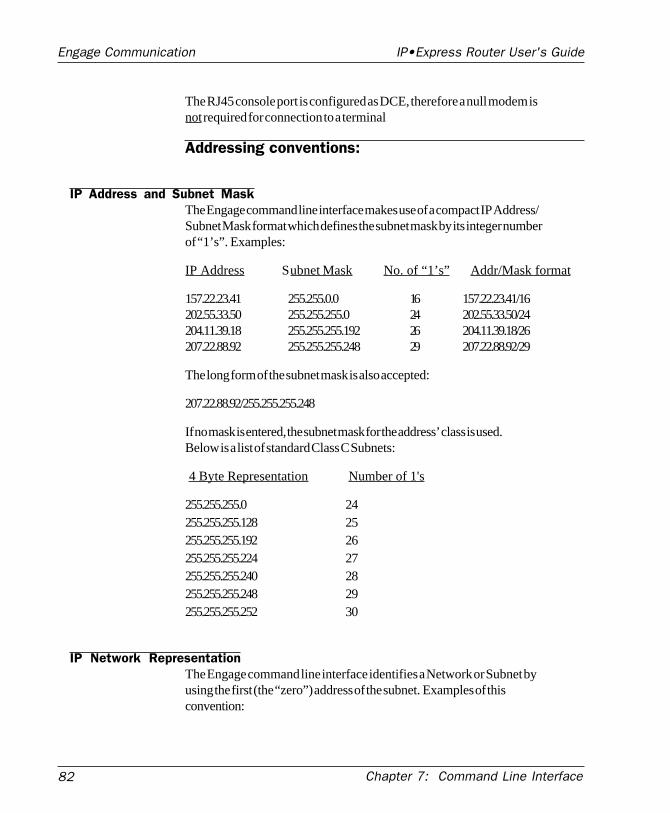
82
Engage Communication IP•Express Router User's Guide
Chapter 7: Command Line Interface
The RJ45 console port is configured as DCE, therefore a null modem isnot required for connection to a terminal
Addressing conventions:
IP Address and Subnet MaskThe Engage command line interface makes use of a compact IP Address/Subnet Mask format which defines the subnet mask by its integer numberof “1’s”. Examples:
IP Address Subnet Mask No. of “1’s” Addr/Mask format
157.22.23.41 255.255.0.0 16 157.22.23.41/16202.55.33.50 255.255.255.0 24 202.55.33.50/24204.11.39.18 255.255.255.192 26 204.11.39.18/26207.22.88.92 255.255.255.248 29 207.22.88.92/29
The long form of the subnet mask is also accepted:
207.22.88.92/255.255.255.248
If no mask is entered, the subnet mask for the address’ class is used.Below is a list of standard Class C Subnets:
4 Byte Representation Number of 1's
255.255.255.0 24255.255.255.128 25255.255.255.192 26255.255.255.224 27255.255.255.240 28255.255.255.248 29255.255.255.252 30
IP Network RepresentationThe Engage command line interface identifies a Network or Subnet byusing the first (the “zero”) address of the subnet. Examples of thisconvention:
Chapter 7: Command Line Interface 83
Engage Communication IP•Express Router User's Guide
IP Subnet Network Address Range Mask Representation 202.55.33.0 to 202.55.33.255 255.255.255.0 202.55.33.0/24 204.99.13.64 to 204.99.13.127 255.255.255.192 204.99.13.64/26 207.22.88.8 to 207.22.88.15 255.255.255.248 207.22.88.8/29
Establishing a Telnet session
A Telnet session is opened by providing the IP address of the router. Onopening a Telnet session with an Engage router, the login promptrequires entry of a User ID. The default User ID: root.
Engage routers are shipped with no password set. Passwords are set ormodified with the passwd command, detailed below. The Telnetpassword is the same as the EngageView Administrator's password.
Overview of Engage Commands
A full description of the Engage command line interface follows. Addi-tionally, the entire list is provided in the Appendices section.
CategoriesThe command set can be divided into four categories:
GeneralShowConfigConfig Interface
HELPIncluded in the General commands is the HELP command, providinginformation on the entire command set.
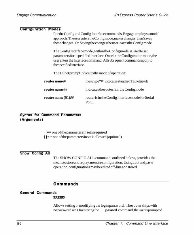
84
Engage Communication IP•Express Router User's Guide
Chapter 7: Command Line Interface
Configuration ModesFor the Config and Config Interface commands, Engage employs a modalapproach. The user enters the Config mode, makes changes, then Savesthose changes. On Saving the changes the user leaves the Config mode.
The Config Interface mode, within the Config mode, is used to setparameters for a specified interface. Once in the Configuration mode, theuser enters the Interface command. All subsequent commands apply tothe specified interface.
The Telnet prompt indicates the mode of operation:
router name# the single “#” indicates standard Telnet mode
router name## indicates the router is in the Config mode
router name (S1)## router is in the Config Interface mode for SerialPort 1
Syntax for Command Parameters(Arguments)
{} == one of the parameters in set is required[ ] = = one of the parameters in set is allowed (optional)
Show Config AllThe SHOW CONFIG ALL command, outlined below, provides themeans to store and replay an entire configuration. Using a cut and pasteoperation, configurations may be edited off-line and stored.
Commands
General CommandsPASSWD
Allows setting or modifying the login password. The router ships withno password set. On entering the passwd command, the user is prompted
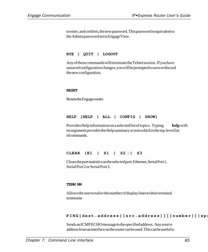
Chapter 7: Command Line Interface 85
Engage Communication IP•Express Router User's Guide
to enter, and confirm, the new password. This password is equivalent tothe Admin password set in EngageView.
BYE | QUIT | LOGOUT
Any of these commands will terminate the Telnet session. If you haveunsaved configuration changes, you will be prompted to save or discardthe new configuration.
RESET
Resets the Engage router.
HELP [HELP | ALL | CONFIG | SHOW]
Provides Help information on a selected list of topics. Typing help withno argument provides the Help summary screen which is the top-level listof commands.
CLEAR {E1 | S1 | S2 | S3}
Clears the port statistics on the selected port: Ethernet, Serial Port 1,Serial Port 2 or Serial Port 3.
TERM NN
Allows the user to tailor the number of display lines to their terminalscreen size
PING{dest.address}[src.address][[{number}]|spr
Sends an ICMP ECHO message to the specified address. Any sourceaddress from an interface on the router can be used. This can be useful to
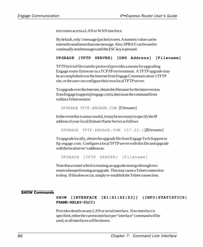
86
Engage Communication IP•Express Router User's Guide
Chapter 7: Command Line Interface
test routes across a LAN or WAN interface.
By default, only 1 message (packet) is sent. A numeric value can beentered to send more than one message. Also, SPRAY can be used tocontinually send messages until the ESC key is pressed.
UPGRADE {TFTP SERVER} [DNS Address] [Filename]
TFTP (trivial file transfer protocol) provides a means for upgradingEngage router firmware in a TCP/IP environment. A TFTP upgrade maybe accomplished over the Internet from Engage Communication’s TFTPsite, or the user can configure their own local TFTP server.
To upgrade over the Internet, obtain the filename for the latest versionfrom Engage ([email protected]), then issue the command fromwithin a Telnet session:
UPGRADE TFTP.ENGAGE.COM [Filename]
In the event this is unsuccessful, it may be necessary to specify the IPaddress of your local Domain Name Server as follows
UPGRADE TFTP.ENGAGE.COM 157.22.1.1 [Filename]
To upgrade locally, obtain the upgrade file from Engage Tech Support orftp.engage.com. Configure a local TFTP server with this file and upgradewith the local server’s address as:
UPGRADE {TFTP SERVER} [Filename]
Note that a router which is running an upgrade must go through tworesets when performing an upgrade. This may cause a Telnet connectionto drop. If this does occur, simply re-establish the Telnet connection.
SHOW CommandsSHOW [INTERFACE [E1|S1|S2|S3]] {INFO|STATISTICS|FRAME-RELAY-DLCI}
Provides details on any LAN or serial interface. If no interface isspecified, either the current interface per “interface” command will beused, or all interfaces will be shown.
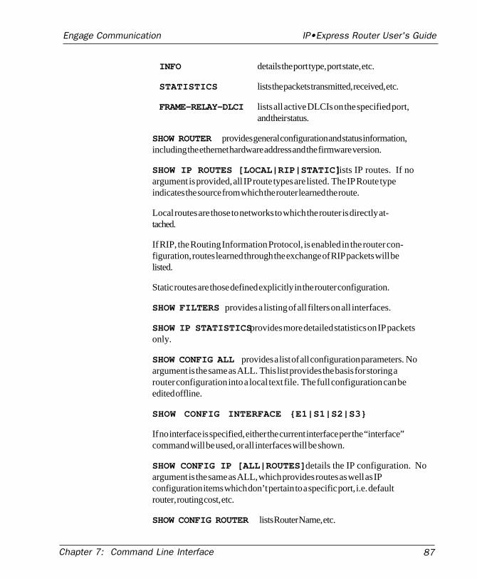
Chapter 7: Command Line Interface 87
Engage Communication IP•Express Router User's Guide
INFO details the port type, port state, etc.
STATISTICS lists the packets transmitted, received, etc.
FRAME-RELAY-DLCI lists all active DLCIs on the specified port,and their status.
SHOW ROUTER provides general configuration and status information,including the ethernet hardware address and the firmware version.
SHOW IP ROUTES [LOCAL|RIP|STATIC] lists IP routes. If noargument is provided, all IP route types are listed. The IP Route typeindicates the source from which the router learned the route.
Local routes are those to networks to which the router is directly at-tached.
If RIP, the Routing Information Protocol, is enabled in the router con-figuration, routes learned through the exchange of RIP packets will belisted.
Static routes are those defined explicitly in the router configuration.
SHOW FILTERS provides a listing of all filters on all interfaces.
SHOW IP STATISTICS provides more detailed statistics on IP packetsonly.
SHOW CONFIG ALL provides a list of all configuration parameters. Noargument is the same as ALL. This list provides the basis for storing arouter configuration into a local text file. The full configuration can beedited offline.
SHOW CONFIG INTERFACE {E1|S1|S2|S3}
If no interface is specified, either the current interface per the “interface”command will be used, or all interfaces will be shown.
SHOW CONFIG IP [ALL|ROUTES] details the IP configuration. Noargument is the same as ALL, which provides routes as well as IPconfiguration items which don’t pertain to a specific port, i.e. defaultrouter, routing cost, etc.
SHOW CONFIG ROUTER lists Router Name, etc.
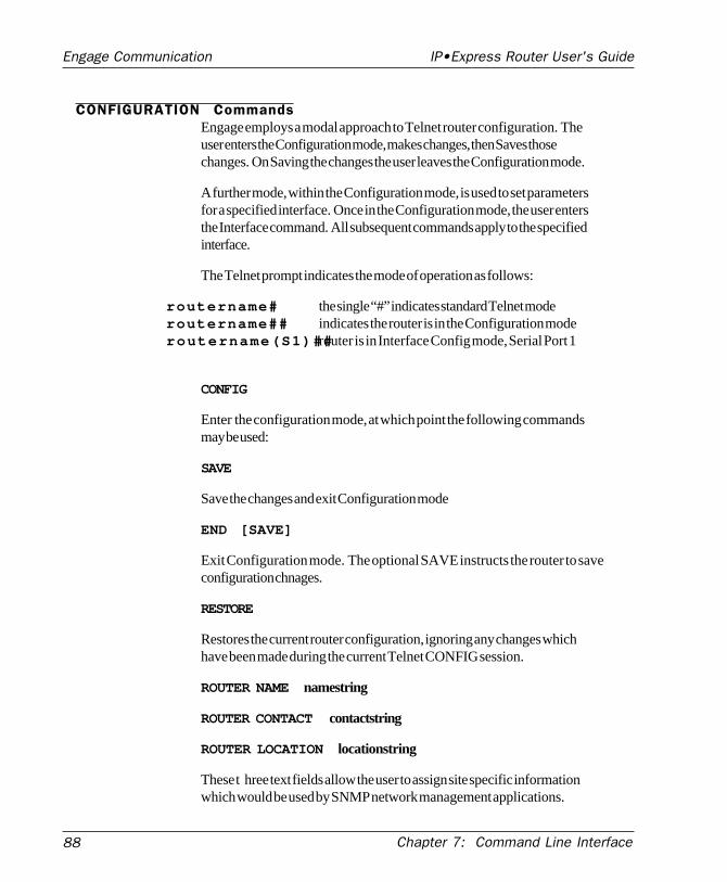
88
Engage Communication IP•Express Router User's Guide
Chapter 7: Command Line Interface
CONFIGURATION CommandsEngage employs a modal approach to Telnet router configuration. Theuser enters the Configuration mode, makes changes, then Saves thosechanges. On Saving the changes the user leaves the Configuration mode.
A further mode, within the Configuration mode, is used to set parametersfor a specified interface. Once in the Configuration mode, the user entersthe Interface command. All subsequent commands apply to the specifiedinterface.
The Telnet prompt indicates the mode of operation as follows:
routername# the single “#” indicates standard Telnet moderoutername## indicates the router is in the Configuration moderoutername(S1)##router is in Interface Config mode, Serial Port 1
CONFIG
Enter the configuration mode, at which point the following commandsmay be used:
SAVE
Save the changes and exit Configuration mode
END [SAVE]
Exit Configuration mode. The optional SAVE instructs the router to saveconfiguration chnages.
RESTORE
Restores the current router configuration, ignoring any changes whichhave been made during the current Telnet CONFIG session.
ROUTER NAME namestring
ROUTER CONTACT contactstring
ROUTER LOCATION locationstring
These t hree text fields allow the user to assign site specific informationwhich would be used by SNMP network management applications.
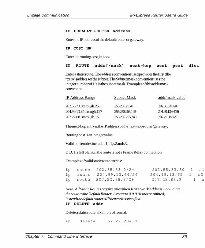
Chapter 7: Command Line Interface 89
Engage Communication IP•Express Router User's Guide
IP DEFAULT-ROUTER address
Enter the IP address of the default router or gateway.
IP COST NN
Enter the routing cost, in hops
IP ROUTE addr[/mask] next-hop cost port dlci
Enter a static route. The address convention used provides the first (the“zero”) address of the subnet. The Subnet mask convention uses theinteger number of 1’s in the subnet mask. Examples of this addr/maskconvention:
IP Address Range Subnet Mask addr/mask value
202.55.33.0 through .255 255.255.255.0 202.55.33.0/24204.99.13.64 through .127 255.255.255.192 204.99.13.64/26207.22.88.8 through .15 255.255.255.248 207.22.88.8/29
The next-hop entry is the IP address of the next-hop router/gateway.
Routing cost is an integer value.
Valid port entries include e1, s1, s2 and s3.
DLCI is left blank if the route is not a Frame Relay connection
Examples of valid static route entries:
ip route 202.55.33.0/24 202.55.33.50 1 s1 ip route 204.99.13.64/26 204.99.13.65 1 s2 ip route 207.22.88.8/29 207.22.88.9 1 e1
Note: All Static Routes require an explicit IP Network Address, includingthe route to the Default Router. A route to 0.0.0.0 is not permitted,instead the default router's IP network is specified.IP DELETE addr
Delete a static route. Example of format:
ip delete 157.22.234.0
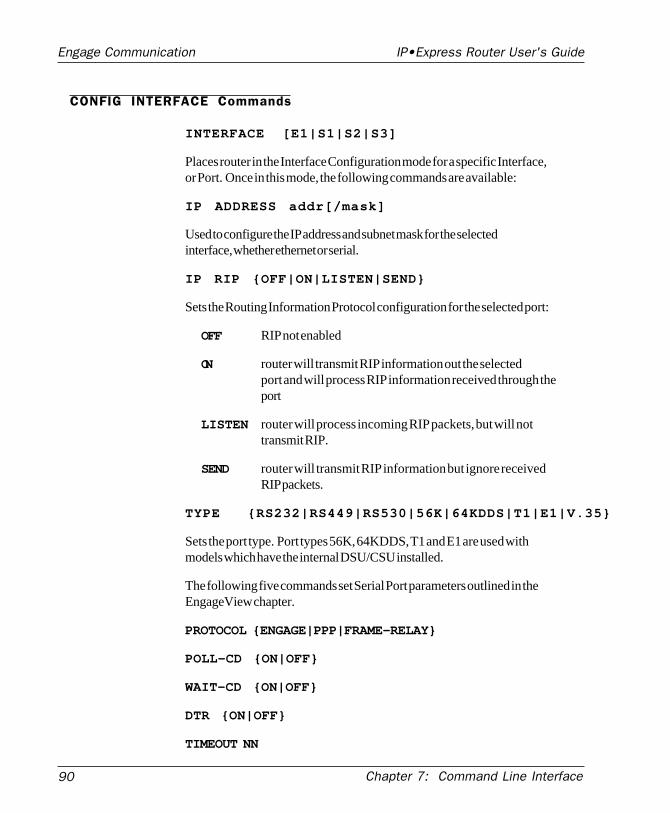
90
Engage Communication IP•Express Router User's Guide
Chapter 7: Command Line Interface
CONFIG INTERFACE Commands
INTERFACE [E1|S1|S2|S3]
Places router in the Interface Configuration mode for a specific Interface,or Port. Once in this mode, the following commands are available:
IP ADDRESS addr[/mask]
Used to configure the IP address and subnet mask for the selectedinterface, whether ethernet or serial.
IP RIP {OFF|ON|LISTEN|SEND}
Sets the Routing Information Protocol configuration for the selected port:
OFF RIP not enabled
ON router will transmit RIP information out the selectedport and will process RIP information received through theport
LISTEN router will process incoming RIP packets, but will nottransmit RIP.
SEND router will transmit RIP information but ignore receivedRIP packets.
TYPE {RS232|RS449|RS530|56K|64KDDS|T1|E1|V.35}
Sets the port type. Port types 56K, 64KDDS, T1 and E1 are used withmodels which have the internal DSU/CSU installed.
The following five commands set Serial Port parameters outlined in theEngageView chapter.
PROTOCOL {ENGAGE|PPP|FRAME-RELAY}
POLL-CD {ON|OFF}
WAIT-CD {ON|OFF}
DTR {ON|OFF}
TIMEOUT NN
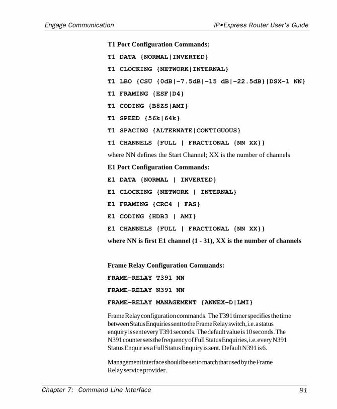
Chapter 7: Command Line Interface 91
Engage Communication IP•Express Router User's Guide
T1 Port Configuration Commands:
T1 DATA {NORMAL|INVERTED}
T1 CLOCKING {NETWORK|INTERNAL}
T1 LBO {CSU {0dB|-7.5dB|-15 dB|-22.5dB}|DSX-1 NN}
T1 FRAMING {ESF|D4}
T1 CODING {B8ZS|AMI}
T1 SPEED {56k|64k}
T1 SPACING {ALTERNATE|CONTIGUOUS}
T1 CHANNELS {FULL | FRACTIONAL {NN XX}}
where NN defines the Start Channel; XX is the number of channels
E1 Port Configuration Commands:
E1 DATA {NORMAL | INVERTED}
E1 CLOCKING {NETWORK | INTERNAL}
E1 FRAMING {CRC4 | FAS}
E1 CODING {HDB3 | AMI}
E1 CHANNELS {FULL | FRACTIONAL {NN XX}}
where NN is first E1 channel (1 - 31), XX is the number of channels
Frame Relay Configuration Commands:
FRAME-RELAY T391 NN
FRAME-RELAY N391 NN
FRAME-RELAY MANAGEMENT {ANNEX-D|LMI}
Frame Relay configuration commands. The T391 timer specifies the timebetween Status Enquiries sent to the Frame Relay switch, i.e. a statusenquiry is sent every T391 seconds. The default value is 10 seconds. TheN391 counter sets the frequency of Full Status Enquiries, i.e. every N391Status Enquiries a Full Status Enquiry is sent. Default N391 is 6.
Management interface should be set to match that used by the FrameRelay service provider.
92
Engage Communication IP•Express Router User's Guide
Chapter 7: Command Line Interface
Config Filter Commands
Filter commands are detailed in Chapter 8: Network Security
FILTER [IN|OUT]
PERMIT|DENY [INTERFACE {E1|S1|S2} .....
DELETE ALL
Initial IP Address Assignment with Telnet
Telnet can be used to assign an IP address to an “unknown” router - onein which IP is not enabled or has an unknown IP address.
The user should power up the router and immediately attempt a Telnetconnection to the desired IP address. If the Telnet session returns aconnection failure, the user should retry immediately - without restartingthe router. Repeat these retries for a total of two minutes.
When the sequence is successful, the user will be asked to confirm thatthe router should adopt the new IP address. If the response is yes, therouter adopts the new address permanently and restarts. If the response isno, the router ends the Telnet session and reverts to the previouslyconfigured IP address. If there was no IP address configured, IP willbecome unavailable.
Once the address assignment is complete, the user will need to assignfurther IP parameters including the subnet mask.
If the method does not work the first time, the router should be restartedto initiate the procedure again, as some of the timing constraints may nothave been met. This method relies on the Telnet workstation generatingARP requests to the desired IP address. It may be helpful to restart theworkstation to clear its ARP cache.

Chapter 8: Network Security 93
Engage Communication IP•Express Router User's Guide
Chapter 8:Network Security

94
Engage Communication IP•Express Router User's Guide
Chapter 8: Network Security
Chapter 8: Network Security 95
Engage Communication IP•Express Router User's Guide
Chapter 8
Network Security
Engage routers provide a number of network security options. For TCP/IP networks, Engage’s IP Packet Filtering allows creation of highlyselective filters to permit or deny access in any direction through anyrouter port.
IP Packet Filtering
Engage IP packet filtering allows the creation of rule sets which selec-tively block TCP/IP packets on a specified interface. Filters are appliedindependently to all interfaces, ethernet and serial, as well as indepen-dently to interface direction: input (packets coming in to the router) oroutput (packets transmitted out of the router).
Packet filtering is used to prevent unauthorized access to your internalnetwork as well as to limit internal user access to services across theWAN. Complex filters can be constructed. One example would be afilter which prevents external users from establishing Telnet sessions toany internal hosts while permitting selected internal users to establishTelnet sessions to external hosts.
Improperly constructed filters can yield unexpected results. Examplefilters are provided, but it is recommended that users completely familiar-ize themselves with the filtering rules in the next section before applyingfilters to their own routers.
96
Engage Communication IP•Express Router User's Guide
Chapter 8: Network Security
Basic Filtering Rules
WAN Router FiltersFilters are often applied to WAN routers by a network administrator viathe internal LAN. To avoid inadvertantly restricting the administrator’sown access to the router, it is advisable to apply all filters to the serial(WAN) port rather than the ethernet (LAN) port.
Default Packet DenyFilters are applied to an interface and direction, for example to s1 out . Ifa single filter command is applied to an interface-direction, all packetsnot explicitly permitted will be denied.
If no filter is applied to an interface-direction, all packets are permitted.
Filter Rule Orderinga. Filter rules are applied in the order in which they were entered by theuser.
b. A packet will be checked against the rules until a match, either apermit or deny, is encountered. No further rules are checked.
c. If possible, place filters which will apply to the largest number ofpackets at the beginning of the list. This increases efficiency.
Ramifications of these rulesa. Generally the user will place Permit filters before Deny filters
b. One exception is a wild card Permit rule placed at the end of the rulelist which will Permit all packets not explicitly denied:
Permit all or Permit 0.0.0.0 0.0.0.0
Chapter 8: Network Security 97
Engage Communication IP•Express Router User's Guide
Clearing FiltersFilters may be cleared through the use of the delete command, outlinedbelow.
Additionally, power cycling the Engage router with DIP Switch 4 turnedON will delete all filters, useful if users lock themselves out.
Command Format
Filter Entry ModeFilter entry is accomplished through a Command Line session with therouter. The default login is root after which the router responds withthe prompt:
RouterName#
To enter filters, you must be in Configuration mode by typing config .The prompt changes to:
RouterName##
An interface must be selected using the command:
interface [e1 | s1 | s2 | s3] .
The next prompt indicates selected interface:
RouterName (S2)##
The filter command is used to define the direction of filters.
filter [in | out]
filter in - Begin command entry for input filters. Input filters apply topackets received IN to the router through the specified port. The Com-mand Line prompt indicates a left arrow:
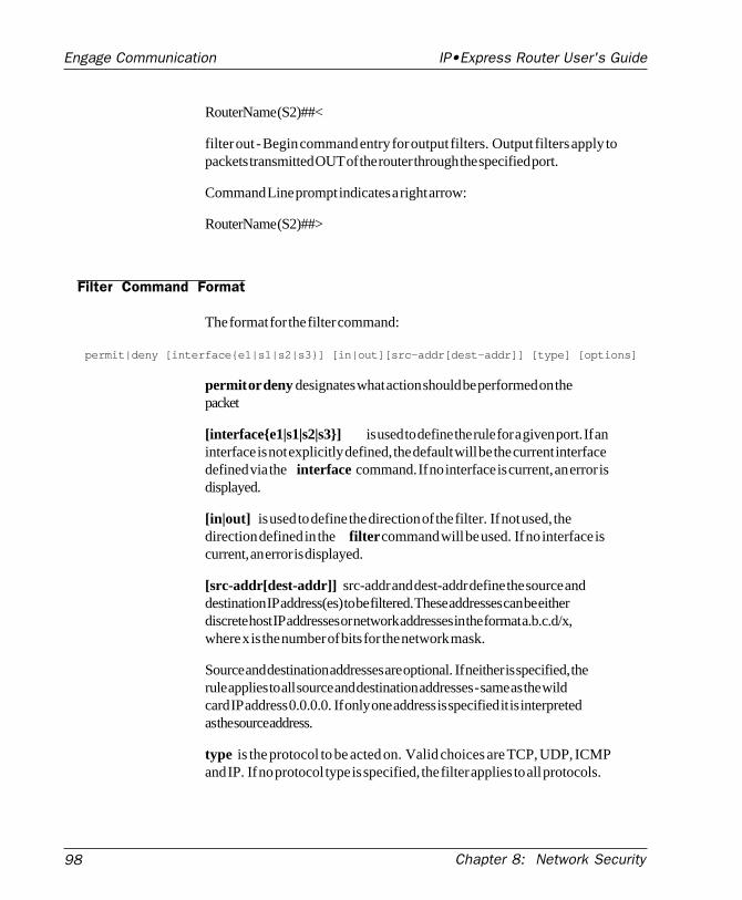
98
Engage Communication IP•Express Router User's Guide
Chapter 8: Network Security
RouterName (S2)##<
filter out - Begin command entry for output filters. Output filters apply topackets transmitted OUT of the router through the specified port.
Command Line prompt indicates a right arrow:
RouterName (S2)##>
Filter Command Format
The format for the filter command:
permit|deny [interface{e1|s1|s2|s3}] [in|out][src-addr[dest-addr]] [type] [options]
permit or deny designates what action should be performed on thepacket
[interface{e1|s1|s2|s3}] is used to define the rule for a given port. If aninterface is not explicitly defined, the default will be the current interfacedefined via the interface command. If no interface is current, an error isdisplayed.
[in|out] is used to define the direction of the filter. If not used, thedirection defined in the filter command will be used. If no interface iscurrent, an error is displayed.
[src-addr[dest-addr]] src-addr and dest-addr define the source anddestination IP address(es) to be filtered. These addresses can be eitherdiscrete host IP addresses or network addresses in the format a.b.c.d/x,where x is the number of bits for the network mask.
Source and destination addresses are optional. If neither is specified, therule applies to all source and destination addresses - same as the wildcard IP address 0.0.0.0. If only one address is specified it is interpretedas the source address.
type is the protocol to be acted on. Valid choices are TCP, UDP, ICMPand IP. If no protocol type is specified, the filter applies to all protocols.
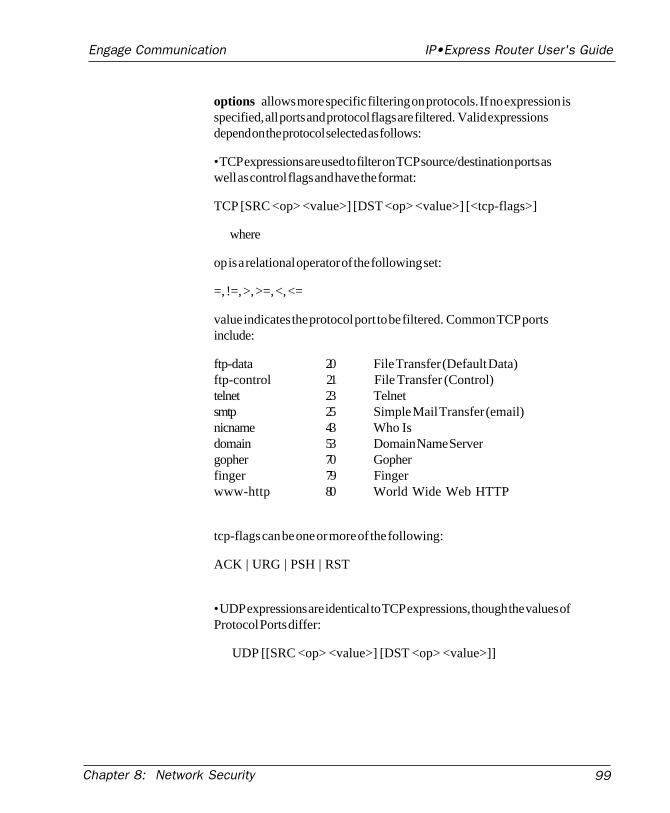
Chapter 8: Network Security 99
Engage Communication IP•Express Router User's Guide
options allows more specific filtering on protocols. If no expression isspecified, all ports and protocol flags are filtered. Valid expressionsdepend on the protocol selected as follows:
• TCP expressions are used to filter on TCP source/destination ports aswell as control flags and have the format:
TCP [SRC <op> <value>] [DST <op> <value>] [<tcp-flags>]
where
op is a relational operator of the following set:
=, !=, >, >=, <, <=
value indicates the protocol port to be filtered. Common TCP portsinclude:
ftp-data 20 File Transfer (Default Data)ftp-control 21 File Transfer (Control)telnet 23 Telnetsmtp 25 Simple Mail Transfer (email)nicname 43 Who Isdomain 53 Domain Name Servergopher 70 Gopherfinger 79 Fingerwww-http 80 World Wide Web HTTP
tcp-flags can be one or more of the following:
ACK | URG | PSH | RST
• UDP expressions are identical to TCP expressions, though the values ofProtocol Ports differ:
UDP [[SRC <op> <value>] [DST <op> <value>]]
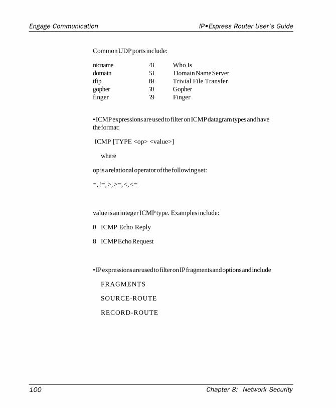
100
Engage Communication IP•Express Router User's Guide
Chapter 8: Network Security
Common UDP ports include:
nicname 43 Who Isdomain 53 Domain Name Servertftp 69 Trivial File Transfergopher 70 Gopherfinger 79 Finger
• ICMP expressions are used to filter on ICMP datagram types and havethe format:
ICMP [TYPE <op> <value>]
where
op is a relational operator of the following set:
=, !=, >, >=, <, <=
value is an integer ICMP type. Examples include:
0 ICMP Echo Reply
8 ICMP Echo Request
• IP expressions are used to filter on IP fragments and options and include
FRAGMENTS
SOURCE-ROUTE
RECORD-ROUTE
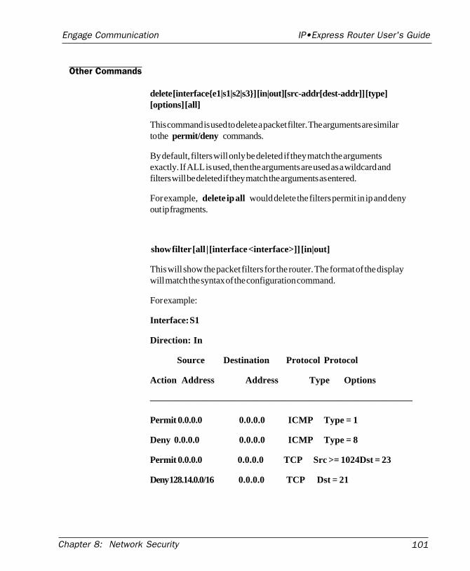
Chapter 8: Network Security 101
Engage Communication IP•Express Router User's Guide
Other Commands
delete [interface{e1|s1|s2|s3}] [in|out][src-addr[dest-addr]] [type][options] [all]
This command is used to delete a packet filter. The arguments are similarto the permit/deny commands.
By default, filters will only be deleted if they match the argumentsexactly. If ALL is used, then the arguments are used as a wildcard andfilters will be deleted if they match the arguments as entered.
For example, delete ip all would delete the filters permit in ip and denyout ip fragments.
show filter [all | [interface <interface>]] [in|out]
This will show the packet filters for the router. The format of the displaywill match the syntax of the configuration command.
For example:
Interface: S1
Direction: In
Source Destination Protocol Protocol
Action Address Address Type Options
————————————————————————————
Permit 0.0.0.0 0.0.0.0 ICMP Type = 1
Deny 0.0.0.0 0.0.0.0 ICMP Type = 8
Permit 0.0.0.0 0.0.0.0 TCP Src >= 1024Dst = 23
Deny 128.14.0.0/16 0.0.0.0 TCP Dst = 21
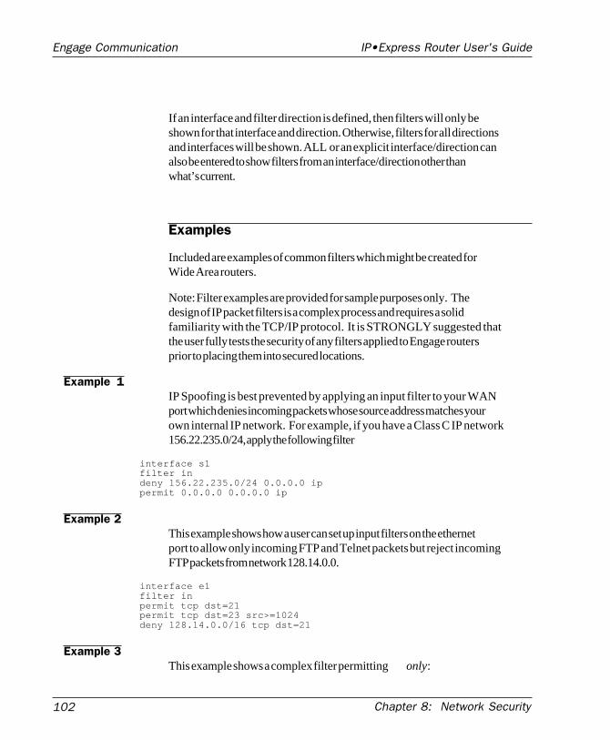
102
Engage Communication IP•Express Router User's Guide
Chapter 8: Network Security
If an interface and filter direction is defined, then filters will only beshown for that interface and direction. Otherwise, filters for all directionsand interfaces will be shown. ALL or an explicit interface/direction canalso be entered to show filters from an interface/direction other thanwhat’s current.
Examples
Included are examples of common filters which might be created forWide Area routers.
Note: Filter examples are provided for sample purposes only. Thedesign of IP packet filters is a complex process and requires a solidfamiliarity with the TCP/IP protocol. It is STRONGLY suggested thatthe user fully tests the security of any filters applied to Engage routersprior to placing them into secured locations.
Example 1IP Spoofing is best prevented by applying an input filter to your WANport which denies incoming packets whose source address matches yourown internal IP network. For example, if you have a Class C IP network156.22.235.0/24, apply the following filter
interface s1filter indeny 156.22.235.0/24 0.0.0.0 ippermit 0.0.0.0 0.0.0.0 ip
Example 2This example shows how a user can set up input filters on the ethernetport to allow only incoming FTP and Telnet packets but reject incomingFTP packets from network 128.14.0.0.
interface e1filter inpermit tcp dst=21permit tcp dst=23 src>=1024deny 128.14.0.0/16 tcp dst=21
Example 3This example shows a complex filter permitting only:
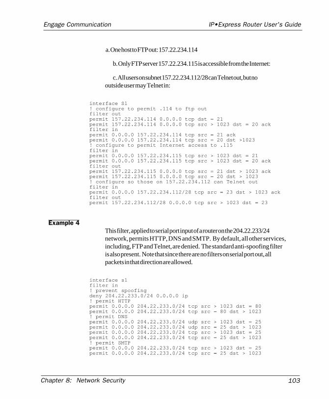
Chapter 8: Network Security 103
Engage Communication IP•Express Router User's Guide
a. One host to FTP out: 157.22.234.114
b. Only FTP server 157.22.234.115 is accessible from the Internet:
c. All users on subnet 157.22.234.112/28 can Telnet out, but nooutside user may Telnet in:
interface S1! configure to permit .114 to ftp outfilter outpermit 157.22.234.114 0.0.0.0 tcp dst = 21permit 157.22.234.114 0.0.0.0 tcp src > 1023 dst = 20 ackfilter inpermit 0.0.0.0 157.22.234.114 tcp src = 21 ackpermit 0.0.0.0 157.22.234.114 tcp src = 20 dst >1023! configure to permit Internet access to .115filter inpermit 0.0.0.0 157.22.234.115 tcp src > 1023 dst = 21permit 0.0.0.0 157.22.234.115 tcp src > 1023 dst = 20 ackfilter outpermit 157.22.234.115 0.0.0.0 tcp src = 21 dst > 1023 ackpermit 157.22.234.115 0.0.0.0 tcp src = 20 dst > 1023! configure so those on 157.22.234.112 can Telnet outfilter inpermit 0.0.0.0 157.22.234.112/28 tcp src = 23 dst > 1023 ackfilter outpermit 157.22.234.112/28 0.0.0.0 tcp src > 1023 dst = 23
Example 4This filter, applied to serial port input of a router on the 204.22.233/24network, permits HTTP, DNS and SMTP. By default, all other services,including, FTP and Telnet, are denied. The standard anti-spoofing filteris also present. Note that since there are no filters on serial port out, allpackets in that direction are allowed.
interface s1filter in! prevent spoofingdeny 204.22.233.0/24 0.0.0.0 ip! permit HTTPpermit 0.0.0.0 204.22.233.0/24 tcp src > 1023 dst = 80permit 0.0.0.0 204.22.233.0/24 tcp src = 80 dst > 1023! permit DNSpermit 0.0.0.0 204.22.233.0/24 udp src > 1023 dst = 25permit 0.0.0.0 204.22.233.0/24 udp src = 25 dst > 1023permit 0.0.0.0 204.22.233.0/24 tcp src > 1023 dst = 25permit 0.0.0.0 204.22.233.0/24 tcp src = 25 dst > 1023! permit SMTPpermit 0.0.0.0 204.22.233.0/24 tcp src > 1023 dst = 25permit 0.0.0.0 204.22.233.0/24 tcp src = 25 dst > 1023

104
Engage Communication IP•Express Router User's Guide
Chapter 8: Network Security

Chapter 9: Troubleshooting 105
Engage Communication IP•Express Router User's Guide
Chapter 9:Troubleshooting

Chapter 9: Troubleshooting106
Engage Communication IP•Express Router User's Guide
Chapter 9: Troubleshooting 107
Engage Communication IP•Express Router User's Guide
Chapter 9
Troubleshooting
Wide Area Network system are subject to problems from a variety ofsources. Fortunately, an organized troubleshooting approach usuallyleads to the area of the problem in short order. It is essential to distin-guish between problems caused by the LAN (network system), the WANequipment (communication equipment), the digital phone service and theEngage router configuration.
This troubleshooting chapter is structured with symptoms in the order theuser might encounter them.
Unable to Communicate with the Local Router
Most installations first require communication with a local router, usuallyfrom the same network as the router itself. Proceed through the followingsymptoms if you are unable to communicate with the local router usingTelnet, EngageView, Ping, etc.
Ethernet/GeneralCause: Network Cabling is faulty
Solution: Verify cabling is good by swapping router cabling with aknown good connection. Check the status LEDs on the 10BaseT hub toconfirm a good connection. If necessary, create a stand-alone LAN withjust the workstation and the router.
Cause: Ethernet interface set improperly on the router
Chapter 9: Troubleshooting108
Engage Communication IP•Express Router User's Guide
Solution: On earlier Engage Routers, identified by the absence of aConsole port on the rear panel, the ethernet port is selected by internalmotherboard DIP Switch 1. Switch 1 is OFF for Thinnet, ON for10BaseT. Models with a Console port have auto-sensing ethernet. SeeChapter 4: Engage Router Hardware.
Cause: User has connected the Engage router model w/ internal T1 DSU/CSU to the T1 line prior to configuration.
Solution: Improper T1 configuration or a large T1 error count cangenerate errors which so overload the processor that communication tothe router is slowed or stopped. Unplug the router from the T1 line. Therouter should immediately recover. Configure the T1 DSU/CSU properlyfor T1 line parameters.
Cause: Router ethernet LED on solid or not flashing
Solution: Normally, the ethernet LED flashes each time a packet istransmitted on to the ethernet. If no activity is observed, router may bedefective. If LED is on solid, the router may have difficulty completing atransmission. In either case, a good test is to remove the router to astand-alone network and retest.
Can’t Communicate with Router -TCP/IP
Cause: IP address is not set properly on the router
Solution: A variety of methods exist for assigning an IP address to anEngage router with an unknown IP address. Telnet, BootRouter andDHCP rely on powering up the router on a LAN with a workstation readyto assign a new address. The application EngageView can assign the IPaddress directly (a non-IP version of EngageView), or the user canconfigure directly through the Console port. These methods are de-scribed in chapters on Command Line Interface and EngageView.
Cause: Workstation not on the same subnet as the router
Solution: During an initial configuration of a router, communicationshould come from within the same net/subnet. With no default router, theEngage router will not be able to reply to communication off its own net.
Chapter 9: Troubleshooting 109
Engage Communication IP•Express Router User's Guide
Cause: IP stack on the workstation not configured
Solution: Ensure that other devices on the same LAN can be pinged, orotherwise 'seen'
Can’t Communicate with Router -EngageView/Macintosh
Cause: Macintosh set to LocalTalk
Solution: In the AppleTalk (or Network) Control Panel, select Ethertalk.
Can’t communicate to the router -Console Port
Cause: Baud Rate, Stop Bits, etc. set wrong on communication applica-tion
Solution: Ensure the communication software is configured for a fixed,asynchronous data rate of 9600 bps, 1 stop bit, no parity, 8 bit fixed
Cause: Transmit and Receive Data swapped
Solution: The console port is configured as a DTE (data terminal equip-ment) port. For connection to other DTE, such as a terminal, a NullModem adapter is required. A 25 pin female/25 pin male null modemadapter is provided with the router.
High Ethernet Error CountCause: Bad cabling
Solution: Check all cabling. Ensure proper 50 ohm termination forThinnet connections. Swap ports on 10BaseT hub to troubleshoot.
Solution: Use alternate ethernet type on the router to prove its ethernetinterface.
Chapter 9: Troubleshooting110
Engage Communication IP•Express Router User's Guide
Unable to Communicate with the Remote Site
Local Router Port LED Stays RedAll equipment has been configured and connected, and the digital phoneservice has been "turned up", yet the port LED remains Red, rather thanturning Green. On a leased or dedicated link, Green indicates receptionof good data from a remote router. On a Frame Relay link, it indicatessuccessful handshake with the telco.
Proceed through the following steps in sequence:
No Serial Port Transmit DataCheck whether the Serial Port Transmit Packet count is increasing byselecting the Serial Port in EngageView and monitoring "Packets Trans-mitted" or by repeatedly issuing the command SHOW INTERFACE S1(or S2 or S3) STATISTICS.
Solution: Router is configured to transmit data only when the CarrierDetect (CD) signal is active. Ensure that the DCE does supply CD (akaDCD) or turn off the Engage router's senstivity to Carrier Detect. CDparameters are found in EngageView's Port menu, under Port Configura-tion - Advanced Options. Command line uses POLL-CD and WAIT-CD,both of which would be set to OFF.
Note : CD is an important control signal and should be monitored fordial-up connections.
Solution: Router is not receiving a Transmit Clock (TxCk) signal fromthe DCE. Verify the cabling between the router and DCE. If using V.35,ensure the use of an Engage cable since there are multiple standards forimplementing V.35 signaling through db25 connectors. Ensure the DCEdoes supply TxCk - a modem only supplies TxCk when configured tooperate in Synchronous mode.
No Serial Port Receive DataCheck whether the Serial Port Receive Packet count is increasing byselecting the Serial Port in EngageView and monitoring "Packets Re-ceived" or by repeatedly issuing the command SHOW INTERFACE S1(or S2 or S3) STATISTICS.
Solution: Router is not getting a Receive Clock (RxCk) signal from theDCE. Verify the cabling between the router and DCE. If using V.35,
Chapter 9: Troubleshooting 111
Engage Communication IP•Express Router User's Guide
ensure the use of an Engage cable since there are multiple standards forimplementing V.35 signaling through db25 connectors. Ensure the DCEdoes supply RxCk.
Solution: Router is not getting Receive Data (RxD) from the DCE. Samecabling issues as previous item on RxCk.
Solution: Remote router is not transmitting data. Have a user at remotesite verify the router is transmitting data.
Solution: Telco path is not complete. Have the telephone companyperform loop tests to ensure their connection to both end points isworking. On leased lines, this simply involves breaking the link andperforming Loop Tests to the DSU/CSU or other customer equipment ineach direction. Frame Relay involves more parties, but the local loop tothe customer router equipment can be "looped up" and tested.
Solution: All Receive Data (RxD) is arriving in error. Receive Packetcount is not moving, but the Total Error Count is increasing, and all areReceive Errors. Quality of the line is very poor - have the telco test itout.
Solution: All Receive Data (RxD) is arriving in error. Receive Packetcount is not moving, but the Total Error Count is increasing, and all areReceive Errors. DSU/CSU is improperly configured for the line - usuallyonly the case in T1/fractional T1 lines. Unplug from T1 line and confirmthe line coding, framing, etc. with the T1 provider.
Received Data is of a DifferentProtocol
Receive Packet count is increasing, but the port LED remains Red.
Solution: Check that the WAN protocol agrees between the Engage routerand the remote unit: Engage, PPP or Frame Relay.
Test Suggestion: Local DTE LoopIf the DCE can perform it, configure the external DCE for a Local (orDTE) Loop. When configured in Local Loop, a data communicationdevice will loop back the router's Transmit Data to its Receive Data port.If connected to a device providing loop, the router will show TxD andRxD packets incrementing at the same rate, and the Port LED should turn
Chapter 9: Troubleshooting112
Engage Communication IP•Express Router User's Guide
to amber (yellow). Successful Local Loop testing proves the router'sTxD, RxD, TxC and RxC circuitry, the cable to the external DCE, and theDTE interface circuitry of the DCE.
Note: Temporarily set WAN Configuration to Engage for DCE loop tests
Note: DCE must supply TxC and RxC during Local Loop for the test topass.
Port LED Goes Amber (Yellow)As noted in Local DTE/DCE Loop section, the router Port LED will goamber or yellow when it detects a loop somewhere on its WAN connec-tion. If the Port LED goes Amber during normal operatin, suspect a loopsomewhere in the circuit, whether at the local data communicationequipment, somewhere in telephone company equipment, or at the remotedata communication equipment.
Port LED Alternates Green/RedCause: The external DCE is not supplying Carrier Detect (CD)
Solution: Set the router to ignore the CD signal through EngageView orthe commands POLL-CD and WAIT-CD, both of which would be set toOFF.
Port LED Green on One Router, Redon the Other
This situation arises when data is transferred properly in one direction,but not in the reverse. Data in each direction is somewhat independentand, for example, a bad RxD circuit on a DSU/CSU can cause this effect.The fact that data is transferring properly in one direction helps narrowthe troubleshooting. Using the points mentioned earlier regarding NoTxD and/or no RxD, the user should be able to examine the "bad" datadirection and narrow down the problem.
Port LED Green, but Cannot Com-municate across WAN
Leased/Dedicated Circuit - If the Port LED on the local router is Greenand the remote router indicates it also has a good connection (Port LEDGreen if an Engage router), you may assume data is flowing in bothdirections.
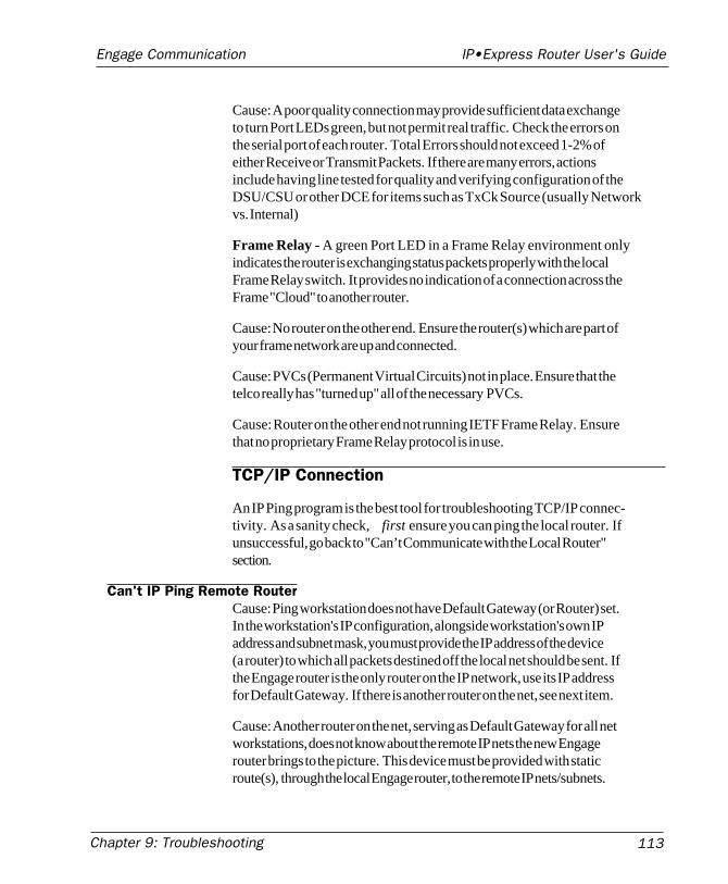
Chapter 9: Troubleshooting 113
Engage Communication IP•Express Router User's Guide
Cause: A poor quality connection may provide sufficient data exchangeto turn Port LEDs green, but not permit real traffic. Check the errors onthe serial port of each router. Total Errors should not exceed 1-2% ofeither Receive or Transmit Packets. If there are many errors, actionsinclude having line tested for quality and verifying configuration of theDSU/CSU or other DCE for items such as TxCk Source (usually Networkvs. Internal)
Frame Relay - A green Port LED in a Frame Relay environment onlyindicates the router is exchanging status packets properly with the localFrame Relay switch. It provides no indication of a connection across theFrame "Cloud" to another router.
Cause: No router on the other end. Ensure the router(s) which are part ofyour frame network are up and connected.
Cause: PVCs (Permanent Virtual Circuits) not in place. Ensure that thetelco really has "turned up" all of the necessary PVCs.
Cause: Router on the other end not running IETF Frame Relay. Ensurethat no proprietary Frame Relay protocol is in use.
TCP/IP Connection
An IP Ping program is the best tool for troubleshooting TCP/IP connec-tivity. As a sanity check, first ensure you can ping the local router. Ifunsuccessful, go back to "Can’t Communicate with the Local Router"section.
Can't IP Ping Remote RouterCause: Ping workstation does not have Default Gateway (or Router) set.In the workstation's IP configuration, alongside workstation's own IPaddress and subnet mask, you must provide the IP address of the device(a router) to which all packets destined off the local net should be sent. Ifthe Engage router is the only router on the IP network, use its IP addressfor Default Gateway. If there is another router on the net, see next item.
Cause: Another router on the net, serving as Default Gateway for all networkstations, does not know about the remote IP nets the new Engagerouter brings to the picture. This device must be provided with staticroute(s), through the local Engage router, to the remote IP nets/subnets.
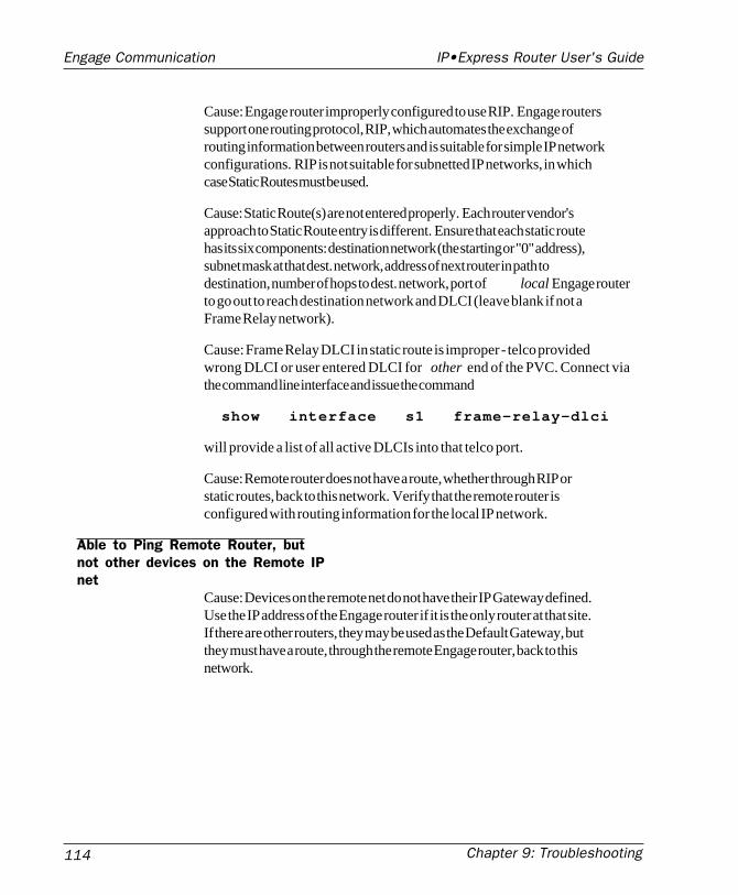
Chapter 9: Troubleshooting114
Engage Communication IP•Express Router User's Guide
Cause: Engage router improperly configured to use RIP. Engage routerssupport one routing protocol, RIP, which automates the exchange ofrouting information between routers and is suitable for simple IP networkconfigurations. RIP is not suitable for subnetted IP networks, in whichcase Static Routes must be used.
Cause: Static Route(s) are not entered properly. Each router vendor'sapproach to Static Route entry is different. Ensure that each static routehas its six components: destination network (the starting or "0" address),subnet mask at that dest. network, address of next router in path todestination, number of hops to dest. network, port of local Engage routerto go out to reach destination network and DLCI (leave blank if not aFrame Relay network).
Cause: Frame Relay DLCI in static route is improper - telco providedwrong DLCI or user entered DLCI for other end of the PVC. Connect viathe command line interface and issue the command
show interface s1 frame-relay-dlci
will provide a list of all active DLCIs into that telco port.
Cause: Remote router does not have a route, whether through RIP orstatic routes, back to this network. Verify that the remote router isconfigured with routing information for the local IP network.
Able to Ping Remote Router, butnot other devices on the Remote IPnet
Cause: Devices on the remote net do not have their IP Gateway defined.Use the IP address of the Engage router if it is the only router at that site.If there are other routers, they may be used as the Default Gateway, butthey must have a route, through the remote Engage router, back to thisnetwork.

Appendices 115
Engage Communication IP•Express Router User's Guide
Appendices

Appendices116
Engage Communication IP•Express Router User's Guide
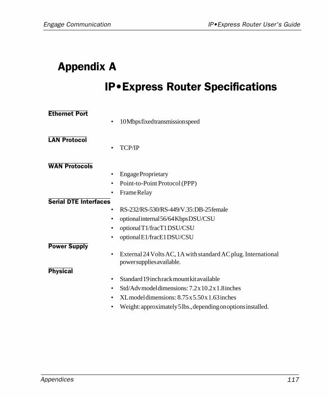
Appendices 117
Engage Communication IP•Express Router User's Guide
Appendix A
IP•Express Router Specifications
Ethernet Port• 10 Mbps fixed transmission speed
LAN Protocol• TCP/IP
WAN Protocols• Engage Proprietary
• Point-to-Point Protocol (PPP)
• Frame Relay
Serial DTE Interfaces• RS-232/RS-530/RS-449/V.35: DB-25 female
• optional internal 56/64 Kbps DSU/CSU
• optional T1/fracT1 DSU/CSU
• optional E1/fracE1 DSU/CSU
Power Supply• External 24 Volts AC, 1A with standard AC plug. International
power supplies available.
Physical• Standard 19 inch rack mount kit available
• Std/Adv model dimensions: 7.2 x 10.2 x 1.8 inches
• XL model dimensions: 8.75 x 5.50 x 1.63 inches
• Weight: approximately 5 lbs., depending on options installed.
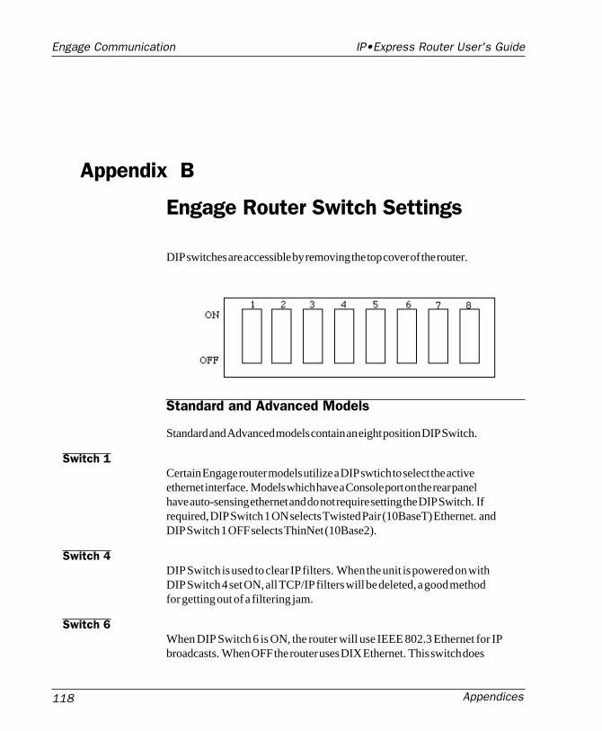
Appendices118
Engage Communication IP•Express Router User's Guide
Appendix B
Engage Router Switch Settings
DIP switches are accessible by removing the top cover of the router.
Standard and Advanced Models
Standard and Advanced models contain an eight position DIP Switch.
Switch 1Certain Engage router models utilize a DIP swtich to select the activeethernet interface. Models which have a Console port on the rear panelhave auto-sensing ethernet and do not require setting the DIP Switch. Ifrequired, DIP Switch 1 ON selects Twisted Pair (10BaseT) Ethernet. andDIP Switch 1 OFF selects ThinNet (10Base2).
Switch 4DIP Switch is used to clear IP filters. When the unit is powered on withDIP Switch 4 set ON, all TCP/IP filters will be deleted, a good methodfor getting out of a filtering jam.
Switch 6When DIP Switch 6 is ON, the router will use IEEE 802.3 Ethernet for IPbroadcasts. When OFF the router uses DIX Ethernet. This switch does
Appendices 119
Engage Communication IP•Express Router User's Guide
not affect IPX header type. The default setting is OFF.
Switch 7Powering the router up when DIP Switch 7 is ON forces the router tofactory default settings. Factory settings include operation from BaseFlash, deleting any download upgrades, and setting AppleTalk seedingON.
XL Router models contain a four position DIP Switch:
Switch 1Powering the router up when DIP Switch 1 is ON forces the router tofactory default settings. Factory settings include operation from BaseFlash, deleting any download upgrades, and setting AppleTalk seedingON.
Switch 3When DIP Switch 3 is ON, the router will use IEEE 802.3 Ethernet for IPbroadcasts. When OFF the router uses DIX Ethernet. This switch doesnot affect IPX header type. The default setting is OFF.
Switch 4DIP Switch is used to clear IP filters. When the unit is powered on withDIP Switch 4 set ON, all TCP/IP filters will be deleted, a good methodfor getting out of a filtering jam.
XL Router Models
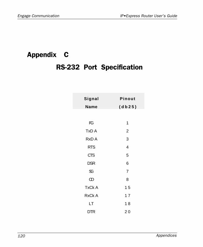
Appendices120
Engage Communication IP•Express Router User's Guide
Appendix C
RS-232 Port Specification
Signal Pinout
Name ( d b 2 5 )
FG 1
TxD A 2
RxD A 3
RTS 4
CTS 5
DSR 6
SG 7
CD 8
TxCk A 1 5
RxCk A 1 7
LT 1 8
DTR 2 0
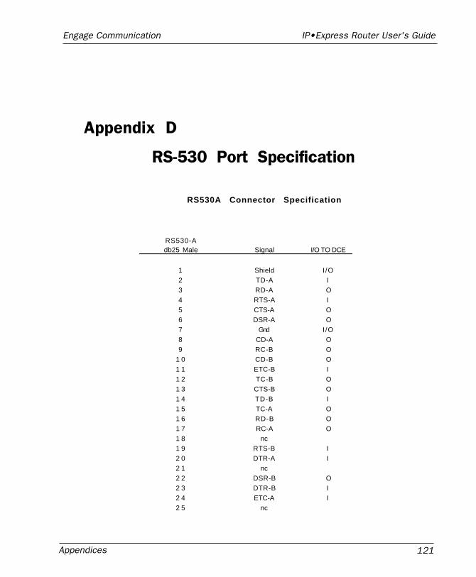
Appendices 121
Engage Communication IP•Express Router User's Guide
Appendix D
RS-530 Port Specification
RS530A Connector Specification
RS530-Adb25 Male Signal I/O TO DCE
1 Shield I /O2 TD-A I3 RD-A O4 RTS-A I5 CTS-A O6 DSR-A O7 Gnd I/O8 CD-A O9 RC-B O
1 0 CD-B O1 1 ETC-B I1 2 TC-B O1 3 CTS-B O1 4 TD-B I1 5 TC-A O1 6 RD-B O1 7 RC-A O1 8 nc1 9 RTS-B I2 0 DTR-A I2 1 nc2 2 DSR-B O2 3 DTR-B I2 4 ETC-A I2 5 nc
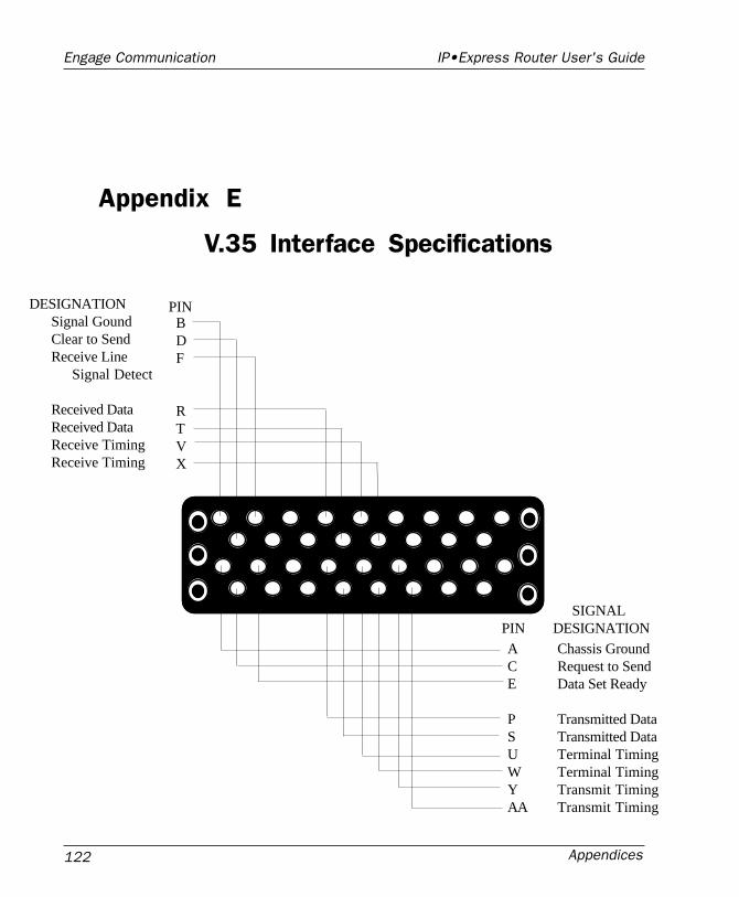
Appendices122
Engage Communication IP•Express Router User's Guide
DESIGNATIONSignal GoundClear to SendReceive Line Signal Detect
Received DataReceived DataReceive TimingReceive Timing
PINBDF
RTVX
PINSIGNAL
DESIGNATION
ACE
PSUWYAA
Chassis GroundRequest to SendData Set Ready
Transmitted DataTransmitted DataTerminal TimingTerminal TimingTransmit TimingTransmit Timing
Appendix E
V.35 Interface Specifications
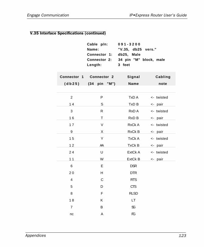
Appendices 123
Engage Communication IP•Express Router User's Guide
V.35 Interface Specifications (continued)
Cable p/n: 0 9 1 - 3 2 0 0Name: "V.35, db25 vers."Connector 1: db25, MaleConnector 2: 34 pin "M" block, maleLength: 3 feet
Connector 1 Connector 2 Signal Cabling
( d b 2 5 ) (34 pin "M") Name note
2 P TxD A <- twisted
1 4 S TxD B <- pair
3 R RxD A <- twisted
1 6 T RxD B <- pair
1 7 V RxCk A <- twisted
9 X RxCk B <- pair
1 5 Y TxCk A <- twisted
1 2 AA TxCk B <- pair
2 4 U ExtCk A <- twisted
1 1 W ExtCk B <- pair
6 E DSR
2 0 H DTR
4 C RTS
5 D CTS
8 F RLSD
1 8 K LT
7 B SG
nc A FG
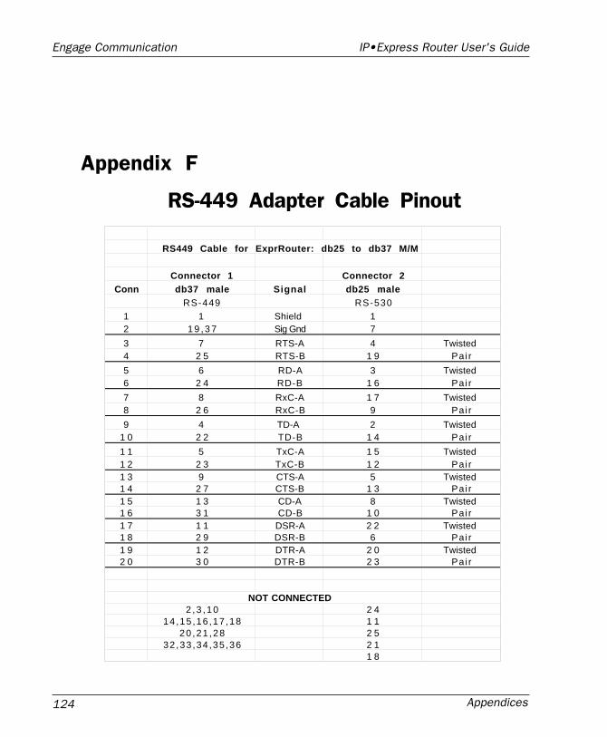
Appendices124
Engage Communication IP•Express Router User's Guide
Appendix F
RS-449 Adapter Cable Pinout
RS449 Cable for ExprRouter: db25 to db37 M/M
Connector 1 Connector 2Conn db37 male Signal db25 male
RS-449 RS-5301 1 Shield 12 1 9 , 3 7 Sig Gnd 7
3 7 RTS-A 4 Twisted 4 2 5 RTS-B 1 9 Pai r
5 6 RD-A 3 Twisted 6 2 4 RD-B 1 6 Pai r
7 8 RxC-A 1 7 Twisted 8 2 6 RxC-B 9 Pai r
9 4 TD-A 2 Twisted 1 0 2 2 TD-B 1 4 Pai r
1 1 5 TxC-A 1 5 Twisted 1 2 2 3 TxC-B 1 2 Pai r1 3 9 CTS-A 5 Twisted 1 4 2 7 CTS-B 1 3 Pai r1 5 1 3 CD-A 8 Twisted 1 6 3 1 CD-B 1 0 Pai r1 7 1 1 DSR-A 2 2 Twisted 1 8 2 9 DSR-B 6 Pai r1 9 1 2 DTR-A 2 0 Twisted 2 0 3 0 DTR-B 2 3 Pai r
NOT CONNECTED2 ,3 ,10 2 4
14,15 ,16 ,17 ,18 1 120 ,21 ,28 2 5
32,33 ,34 ,35 ,36 2 11 8
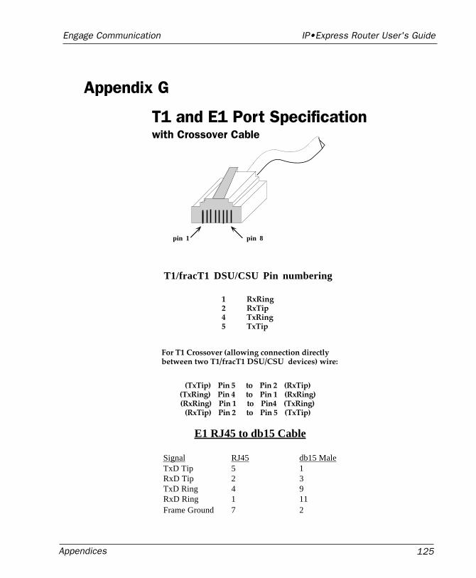
Appendices 125
Engage Communication IP•Express Router User's Guide
Appendix G
T1 and E1 Port Specificationwith Crossover Cable
T1/fracT1 DSU/CSU Pin numbering
For T1 Crossover (allowing connection directly between two T1/fracT1 DSU/CSU devices) wire:
pin 8pin 1
RxRingRxTipTxRingTxTip
1245
(TxTip) Pin 5 to Pin 2 (RxTip)(TxRing) Pin 4 to Pin 1 (RxRing)(RxRing) Pin 1 to Pin4 (TxRing)
(RxTip) Pin 2 to Pin 5 (TxTip)
E1 RJ45 to db15 Cable
Signal RJ45 db15 MaleTxD Tip 5 1RxD Tip 2 3TxD Ring 4 9RxD Ring 1 11Frame Ground 7 2
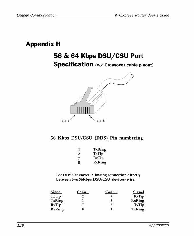
Appendices126
Engage Communication IP•Express Router User's Guide
Appendix H
56 & 64 Kbps DSU/CSU PortSpecification (w/ Crossover cable pinout)
56 Kbps DSU/CSU (DDS) Pin numbering
For DDS Crossover (allowing connection directly between two 56Kbps DSU/CSU devices) wire:
pin 8pin 1
TxRingTxTipRxTipRxRing
1278
SignalTxTipTxRingRxTipRxRing
SignalRxTip
RxRingTxTip
TxRing
Conn 12178
Conn 27821
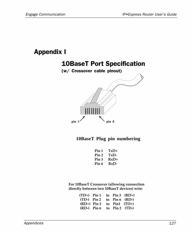
Appendices 127
Engage Communication IP•Express Router User's Guide
Appendix I
10BaseT Port Specification(w/ Crossover cable pinout)
10BaseT Plug pin numbering
For 10BaseT Crossover (allowing connection directly between two 10BaseT devices) wire:
(TD+) Pin 1 to Pin 3 (RD+)(TD-) Pin 2 to Pin 6 (RD-)(RD+) Pin 3 to Pin1 (TD+)(RD-) Pin 6 to Pin 2 (TD-)
pin 8pin 1
Pin 1 TxD+Pin 2 TxD-Pin 3 RxD+Pin 6 RxD-
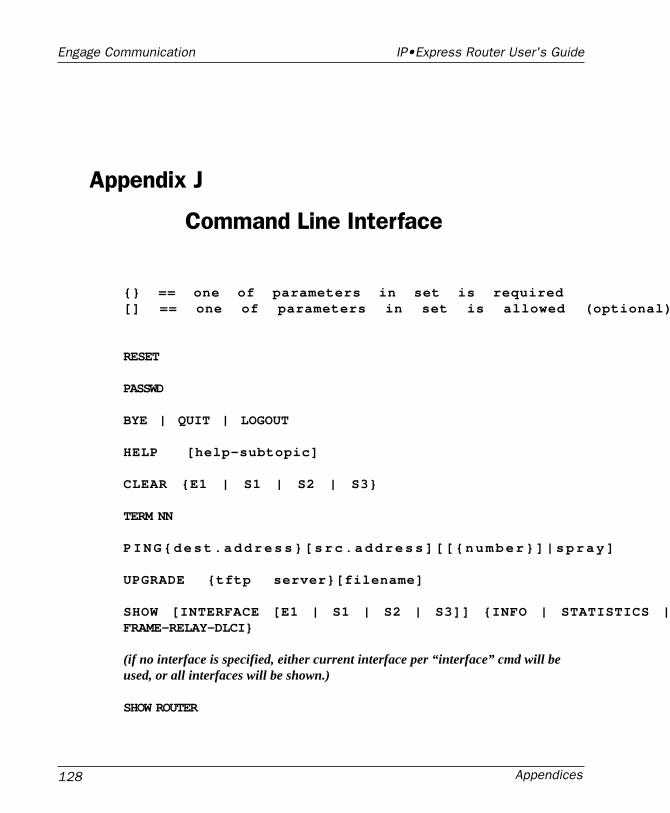
Appendices128
Engage Communication IP•Express Router User's Guide
Appendix J
Command Line Interface
{} == one of parameters in set is required[] == one of parameters in set is allowed (optional)
RESET
PASSWD
BYE | QUIT | LOGOUT
HELP [help-subtopic]
CLEAR {E1 | S1 | S2 | S3}
TERM NN
PING{dest.address}[src.address][[{number}]|spray]
UPGRADE {tftp server}[filename]
SHOW [INTERFACE [E1 | S1 | S2 | S3]] {INFO | STATISTICS |FRAME-RELAY-DLCI}
(if no interface is specified, either current interface per “interface” cmd will beused, or all interfaces will be shown.)
SHOW ROUTER
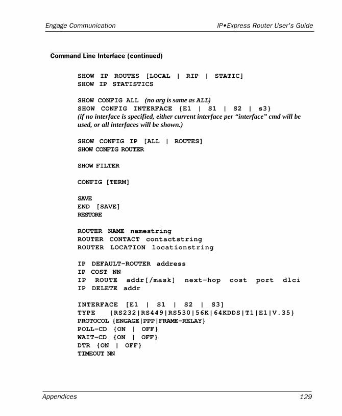
Appendices 129
Engage Communication IP•Express Router User's Guide
Command Line Interface (continued)
SHOW IP ROUTES [LOCAL | RIP | STATIC]SHOW IP STATISTICS
SHOW CONFIG ALL (no arg is same as ALL)SHOW CONFIG INTERFACE {E1 | S1 | S2 | s3}(if no interface is specified, either current interface per “interface” cmd will beused, or all interfaces will be shown.)
SHOW CONFIG IP [ALL | ROUTES]SHOW CONFIG ROUTER
SHOW FILTER
CONFIG [TERM]
SAVEEND [SAVE]RESTORE
ROUTER NAME namestringROUTER CONTACT contactstringROUTER LOCATION locationstring
IP DEFAULT-ROUTER addressIP COST NNIP ROUTE addr[/mask] next-hop cost port dlciIP DELETE addr
INTERFACE [E1 | S1 | S2 | S3]TYPE {RS232|RS449|RS530|56K|64KDDS|T1|E1|V.35}PROTOCOL {ENGAGE|PPP|FRAME-RELAY}POLL-CD {ON | OFF}WAIT-CD {ON | OFF}DTR {ON | OFF}TIMEOUT NN
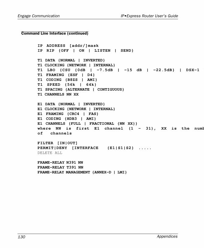
Appendices130
Engage Communication IP•Express Router User's Guide
IP ADDRESS [addr/]maskIP RIP {OFF | ON | LISTEN | SEND}
T1 DATA {NORMAL | INVERTED}T1 CLOCKING {NETWORK | INTERNAL}T1 LBO {CSU {0dB | -7.5dB | -15 dB | -22.5dB} | DSX-1 NT1 FRAMING {ESF | D4}T1 CODING {B8ZS | AMI}T1 SPEED {56k | 64k}T1 SPACING {ALTERNATE | CONTIGUOUS}T1 CHANNELS NN XX
E1 DATA {NORMAL | INVERTED}E1 CLOCKING {NETWORK | INTERNAL}E1 FRAMING {CRC4 | FAS}E1 CODING {HDB3 | AMI}E1 CHANNELS {FULL | FRACTIONAL {NN XX}}where NN is first E1 channel (1 - 31), XX is the numbof channels
FILTER [IN|OUT]PERMIT|DENY [INTERFACE {E1|S1|S2} .....DELETE ALL
FRAME-RELAY N391 NNFRAME-RELAY T391 NNFRAME-RELAY MANAGEMENT {ANNEX-D | LMI}
Command Line Interface (continued)
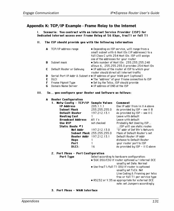
Appendices 131
Engage Communication IP•Express Router User's Guide
Appendix K: TCP/IP Example - Frame Relay to the Internet
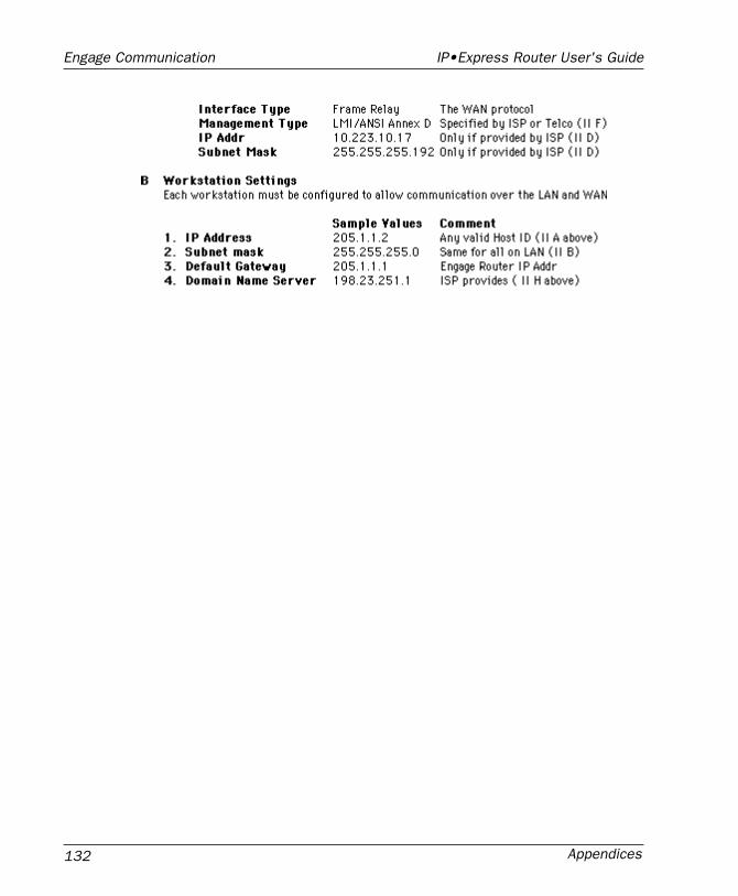
Appendices132
Engage Communication IP•Express Router User's Guide
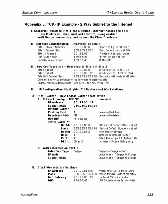
Appendices 133
Engage Communication IP•Express Router User's Guide
Appendix L: TCP/IP Example - 2 Way Subnet to the Internet
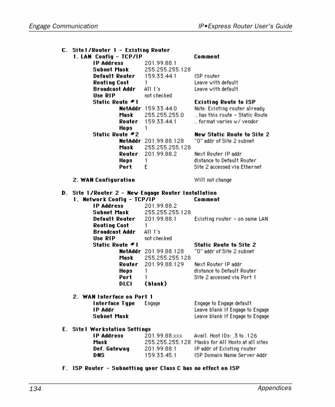
Appendices134
Engage Communication IP•Express Router User's Guide
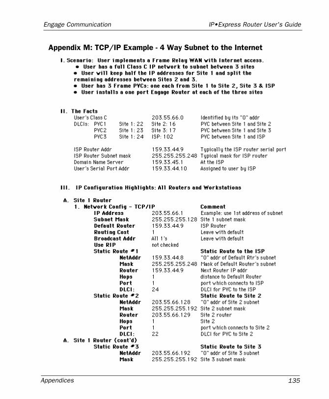
Appendices 135
Engage Communication IP•Express Router User's Guide
Appendix M: TCP/IP Example - 4 Way Subnet to the Internet
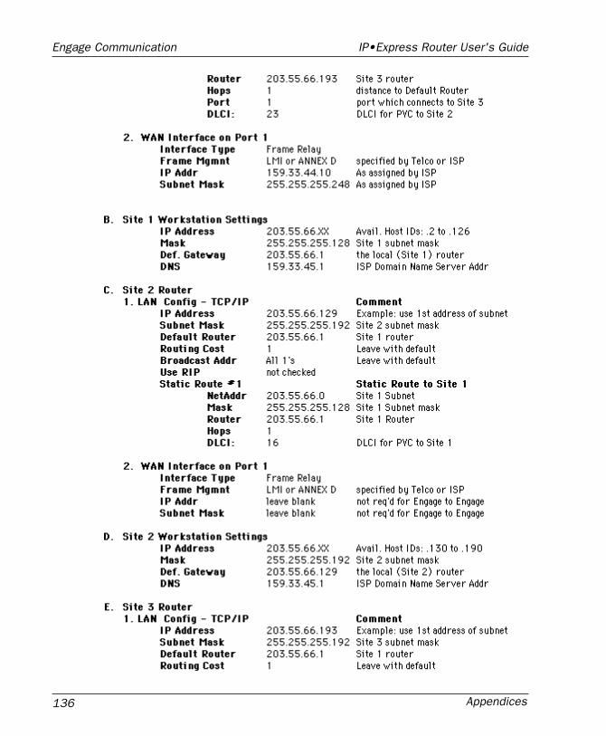
Appendices136
Engage Communication IP•Express Router User's Guide
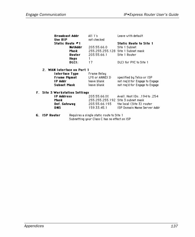
Appendices 137
Engage Communication IP•Express Router User's Guide
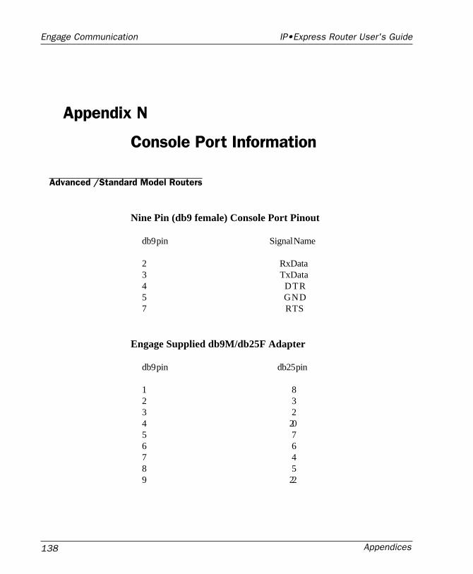
Appendices138
Engage Communication IP•Express Router User's Guide
Appendix N
Console Port Information
Advanced /Standard Model Routers
Nine Pin (db9 female) Console Port Pinout
db9 pin Signal Name
2 RxData3 TxData4 DTR5 GND7 RTS
Engage Supplied db9M/db25F Adapter
db9 pin db25 pin
1 82 33 24 205 76 67 48 59 22
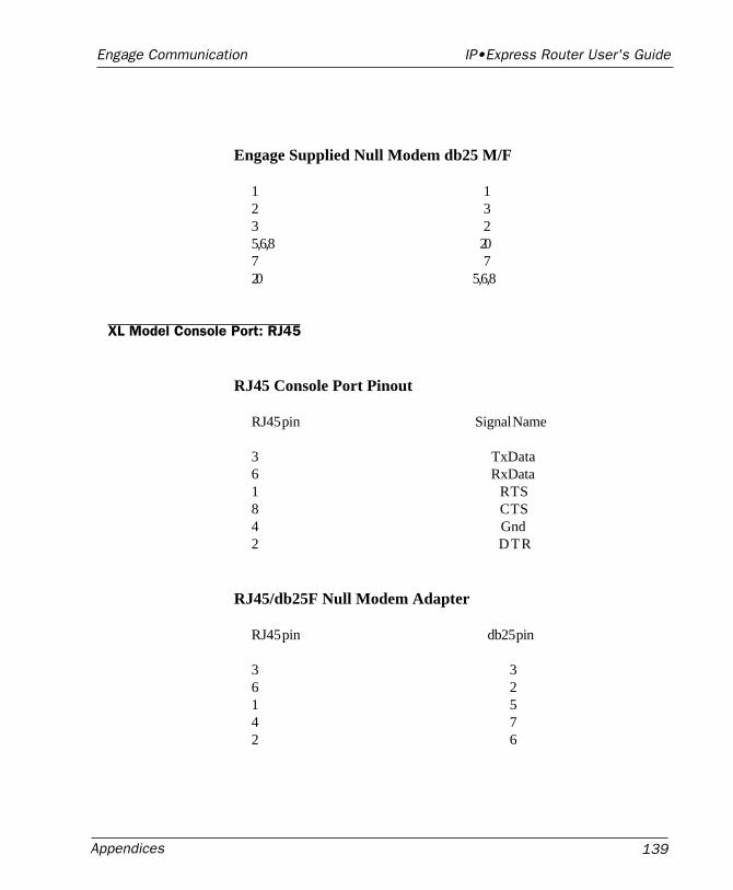
Appendices 139
Engage Communication IP•Express Router User's Guide
Engage Supplied Null Modem db25 M/F
1 12 33 25,6,8 207 720 5,6,8
XL Model Console Port: RJ45
RJ45 Console Port Pinout
RJ45 pin Signal Name
3 TxData6 RxData1 RTS8 CTS4 Gnd2 DTR
RJ45/db25F Null Modem Adapter
RJ45 pin db25 pin
3 36 21 54 72 6

Appendices140
Engage Communication IP•Express Router User's Guide

Glossary 141
Engage Communication IP•Express Router User's Guide
Glossary:Terms and Concepts

Glossary142
Engage Communication IP•Express Router User's Guide
Glossary 143
Engage Communication IP•Express Router User's Guide
Glossary
Terms and Concepts
Before using the Engage Router, you should be familiar with the termsand concepts that describe TCP/IP. If you are experienced with internetrouters, these terms may already be familiar to you.
General Networking Terms
NetworkA network is a collection of computers, server devices, and communica-tion devices connected together and capable of communication with oneanother through a transmission medium.
InternetAn internet is any grouping of two or more networks connected by one ormore internet routers.
Network ServicesNetwork services are the capabilities that the network system delivers tousers, such as print servers, file servers, and electronic mail.
AddressesTransmitting information in a network system is made possible by anaddressing scheme that identifies the sender and destination of thetransmission, using network and node addresses. Data is transmitted toand from these addresses in the form of packets.
Glossary144
Engage Communication IP•Express Router User's Guide
Routing TableA routing table is maintained in each router. This table lists all networksand routers in the internet and enables routers to determine the mostefficient route for each packet. The routing table serves as a logical mapof the internet, specifying the address of the next router in the path to agiven destination network and the distance in hops. The router uses therouting table to determine where and whether to forward a packet.
Each router periodically broadcasts its routing table to other routers oneach of its directly connected networks, enabling them to compare andupdate their own tables with the most recent record of connected net-works and routes. In this way, routing tables are kept current as changesare made on the internet.
HopA hop is a unit count between networks on the internet. A hop signifies“one router away.”
NodeDevice on the network
TCP/IP Networking Terms
FTPFile Transfer Protocol gives users the ability to transfer files between IPhosts. It uses TCP to provide connection initiation and reliable datatransfer.
HostA computer with one or more uses that can act as an endpoint of commu-nication if it has TCP/IP.
ICMPInternet Control Message Protocol provides a means for intermediategateways and hosts to communicate. There are several types of ICMPmessages and they are used for several purposes including IP flowcontrol, routing table correction and host availability.
IPInternet Protocol which routes the data.
Glossary 145
Engage Communication IP•Express Router User's Guide
IP DatagramThe basic unit of the information passed across and IP Internet. Itcontains address information and data.
PINGPacket InterNet Groper is a program which uses ICMP echo requestmessage to check if the specifies IP address is accessible from the currenthost.
PortA Destination point used by transport level protocols to distinguishamong multiple destinations within a given host computer.
RIPRouting Information Protocol provides a means for routers to exchangerouting information. RIP’s messages are encapsulated in UDPdatagrams.
SubNet AddressAn extension of the IP addressing scheme which enables an IP site to usea single IP address for multiple physical networks. Subnetting is appli-cable when a network grows beyond the number of hosts allowed for theIP address class of the site.
TCPTransmission Control Protocol ensures reliable, sequential, delivery ofdata. TCP at each end of the connection ensures that the data is deliveredto the application accurately, sequential, completely and free of dupli-cates. The application passes a stream of bytes to TCP which breaks itinto pieces, adds a header, forming a segment, and then passes eachsegment to IP for transmission.
TelnetThe TCP/IP standard protocol for remote terminal connection service. Auser can telnet from the local host to a host at a remote site.
UDPUser Datagram Protocol provides simple, efficient protocol which isconnectionless and thus unreliable. The IP address contained in the UDPheader is used to direct the datagram to a specific destination host.
Glossary146
Engage Communication IP•Express Router User's Guide
Well-Known PortAny set of port numbers reserved for specific uses vy transport levelprotocols (TCP & UDP). Well-known ports exist for echo servers, timeservers, telnet and FTP servers.
Communication Link Definitions
Data Communication Equipment (DCE)This interfaces to the communication service’s transmission/receptionmedium, and includes T1 Voice/Data Multiplexors, 64/56 Kilobit DSU/CSUs, and Fiber Optic Modems. The DCE provides the transmit andreceive data pathways, along with their synchronous clocking signals,that are used by the Engage Router’s DTE interface for full duplexcommunication between the remotely interconnected networks.
Data Terminal Equipment (DTE)This equipment, such as an Engage Router, attaches to the terminal sideof Data Communication Equipment.
Data Carrier Detect (DCD)A signal that indicates to the DTE that the DCE is receiving a signal froma remote DCE.
Data Terminal Ready (DTR)Prepares the DCE to be connected to the phone line, then the connectioncan be established by dialing. Enables the DCE to answer an incomingcall on a switched line.