IP400 User Guide nopeer - pbxmechanic.com IP400 System... · compresses analog voice signal on...
32
i IPitomy IP400 User Guide
Transcript of IP400 User Guide nopeer - pbxmechanic.com IP400 System... · compresses analog voice signal on...

i
IPitomy IP400 User Guide

ii
Table of Contents
CHAPTER 1 INTRODUCTION ............................................................................................1
VoIP Gateway Features ...................................................................................................1 Package Contents ..............................................................................................................2 Physical Details ..................................................................................................................2
CHAPTER 2 INSTALLATION..............................................................................................1
Requirements .....................................................................................................................1 Procedure............................................................................................................................1
CHAPTER 3 CONFIGURATION AND APPLICATION EXAMPLES .........................2
Configuration.....................................................................................................................2 Application Example 1- Remote Offices........................ Error! Bookmark not defined. Application Example 2- PSTN Trunk for IP PBX.......................................................3
CHAPTER 4 SETUP ................................................................................................................4
Overview .............................................................................................................................4 Configuration Program....................................................................................................4 Basic Setup Screen ............................................................................................................7 SIP Service Screen.............................................................................................................8 Line Settings Screen........................................................................................................10 Voice Screen .....................................................................................................................11 Management Screen........................................................................................................14 Factory Default Screen...................................................................................................15 Firmware Upgrade Screen.............................................................................................16 Reboot Screen ..................................................................................................................17 Gateway Screen ...............................................................................................................18 VoIP Screen......................................................................................................................19 Set Log Level Screen.......................................................................................................20 Event Logs Screen ...........................................................................................................21
APPENDIX A TROUBLESHOOTING...............................................................................22
Overview ...........................................................................................................................22 General Problems............................................................................................................22
APPENDIX B SPECIFICATIONS.......................................................................................24
VoIP Gateway ..................................................................................................................24

iii
P/N: 956YD30001
Copyright 2007. All Rights Reserved.
Document Version: 1.0
All trademarks and trade names are the properties of their respective owners.


1
Chapter 1
Introduction
This Chapter provides an overview of the VoIP Gateway features and ca-
pabilities.
Congratulations on the purchase of your new VoIP Gateway. The VoIP Gateway bridges
traditional Public Switched Telephony Network (PSTN) and IP network. It digitizes and
compresses analog voice signal on Public Switched Telephone Network (PSTN), and
transmits it to the Internet Protocol (IP) network. The VoIP Gateway is equipped with one
RJ-45 port for connecting to IP-based network and four Plain Old Telephone Service
(POTS) ports with Foreign Exchange Office (FXO) interface for connecting to PBX or
Central Office (CO) lines.
VoIP Gateway Features
The VoIP Gateway incorporates many advanced features, carefully designed to provide
sophisticated functions while being easy to use.
Internet Access Feature
• Fixed or Dynamic IP Address support
NAT Traversal Feature
• STUN and UPnP control point protocol for NAT traversal
VoIP Features
• Session Initiation Protocol (SIP) support
• Provides PSTN users access to IP telephony networks
• IP connectivity for traditional PBX and Key Systems
• G.711, G.726 and G.729AB voice codecs support
• Voice activity detection and comfort noise generation
• Packet lost concealment
• Dynamic Jitter Buffer
• Echo cancellation, G.168 32 ms echo tail
• DTMF tone detection and generation
• RFC2833 in-band DTMF relay
• Call progress tone detection
• Caller ID detection
• Hunt grouping of FXO ports
• Built-in dial plan
• Web Based UI for network and image control
1

IP Phone User Guide
2
Package Contents
The following items should be included:
• The VoIP Gateway Unit
• Power Adapter
• One RJ45 Ethernet cable.
• Quick installation guide
• CD-ROM containing the on-line manual.
Physical Details
Figure 1: Front Panel
Front-mounted LEDs
Power On - Power On.
Off - No Power.
Status On - The VoIP Gateway has successfully registered to SIP server.
Flashing - The VoIP Gateway has not registered to SIP server.
LAN On – The LAN port is active.
Off - No active connection on the LAN port.
Flashing - Data is being transmitted or received via the LAN
port.
Line 1, 2, 3 and 4 On - The PSTN port is active.
Off - The PSTN port is not in use.
Flashing - The device connecting to the line is ringing.

Introduction
3
Rear Panel
Figure 2: Rear Panel
Power Connect the supplied power adapter here.
Reset Button This button has two (2) functions:
• Reboot. When pressed for less than 6 seconds and
released, the VoIP Gateway will reboot (restart).
• Clear All Data. When press for 6 seconds longer
then released. ALL data are cleared and restored to
the factory default values, and the VoIP Gateway
will reboot.
LAN
(10/100BaseT)
Connect to a broadband router using a standard LAN
cable.
Line 1~4 Connect to your PSTN phone lines or PBX extension
lines here.


1
Chapter 2
Installation
This Chapter covers the physical installation of the VoIP Gateway.
Requirements
• TCP/IP protocol must be installed on all PCs.
• For Internet Access & VoIP, you must have access to Internet.
Procedure
1. Choose an Installation Site
Select a suitable place on the network to install the VoIP Gateway.
Ensure the VoIP Gateway is powered OFF.
2. Connect LAN Cable
Connect the LAN port of the VoIP Gateway to a router using the standard LAN cable
that is shipped with the VoIP Gateway.
3. Connect Phones
Connect CO lines or PBX extension lines to the FXO ports.
4. Power Up
Connect the supplied power adapter to the VoIP Gateway and power up.
Use only the power adapter provided. Using a different one may cause hardware dam-
age.
5. Check the LEDs
• The Power LED should be ON.
• The LAN LED should be ON.
2

2
Chapter 3
Configuration and Application
Examples This Chapter provides some examples of VoIP Gateway configuration and
application.
Configuration
The VoIP Gateway can be configured to register to a SIP server and make calls through the
server. In SIP server environment, the SIP server handles the registration and serves as a
proxy server for call signal. The VoIP Gateway may be configured to work in Direct
Inward Dial (DID) mode or regular mode. In DID mode, calls originated from FXO ports
are routed to SIP server for termination directly. In regular dialing mode, when an incoming
call is detected from FXO port, the VoIP Gateway plays dial tone and waits for the final
destination number to be dialed. See Line Settings Screen for further details of DID mode
configuration.
3

Configuration and Application Examples
3
Application Example 2- PSTN Trunk for IP PBX
Organization with IP PBX can use the VoIP Gateway as PSTN trunk for connecting its IP
PBX to PSTN. You can configure the IP PBX as VoIP Gateway’s SIP server and setup the
dial plan on the IP PBX, the VoIP Gateway can be used as PSTN trunk to the IP PBX.
Gateway
IP PBX
PSTN

4
Chapter 4
Setup This Chapter provides Setup details of the VoIP Gateway
Overview
This chapter describes the setup procedure for configuring the VoIP Gateway from a web
browser.
After changing the settings, the new set-tings won’t take effect until you save and reset the VoIP Gateway. Use the Reset button on the Reset screen.
Configuration Program
The VoIP Gateway contains an HTTP server. This enables you to connect and configure it
by using your Web Browser. Your web browser must support JavaScript. The configu-
ration program has been tested on the following browsers:
• Netscape V4.08 or later
• Internet Explorer V4 or later
Preparation
Before attempting to configure the VoIP Gateway, please ensure that:
• Your PC can establish a physical connection to network that the VoIP Gateway con-
nects to. The PC and the VoIP Gateway must be on the same LAN segment.
• The VoIP Gateway must be installed and powered ON.
• Ensure that the VoIP Gateway's default IP Address (192.168.0.250) is not used by any
host connecting to the network.
Using your Web Browser
To establish a connection from your PC to the VoIP Gateway:
1. Start your web browser.
2. In the Address box, enter "HTTP://" and the IP Address of the VoIP Gateway, as in this
example, which uses the VoIP Gateway's default IP Address:
http://192.168.0.250
4

Setup
5
If you can't connect
If the VoIP Gateway does not respond, check the following:
• The VoIP Gateway is properly installed, LAN connection is OK, and it is
powered ON. You can test the connection by using the "Ping" command:
• Open the MS-DOS window or command prompt window.
• Enter the command: ping 192.168.0.250
If no response is received, either the connection is not working, or your
PC's IP address is not compatible with the VoIP Gateway's IP Address.
(See next item.)
• If your PC is using a fixed IP Address, its IP Address must be within the range
192.168.0.1 to 192.168.0.254 to be compatible with the VoIP Gateway's de-
fault IP Address of 192.168.0.250. Also, the Network Mask must be set to
255.255.255.0.
• Ensure that your PC and the VoIP Gateway are on the same network segment.
(If you don't have a router, this must be the case.)
Logging In
After connecting to the VoIP Gateway from a web browser, you should then see a login
prompt, which will ask for a User Name and Password.
Figure 3: Login Screen
Enter admin for the User Name, and leave blank for the Password.
These are the default values. The password can and should be changed. Always enter the
current user name and password, as set on the Management screen.

IP400 User Guide
6
Main Menu
The main menu, on the left, contains links to the most-commonly used screen.
From the menu, check the following screens, and configure as necessary for your environ-
ment. Details of these screens and settings are described in the following sections of this
chapter.
• Setup
• Basic Setup,
• SIP Service
• Line Settings
• Voice
• Administration
• Management
• Factory Defaults
• Firmware Upgrade
• Reboot
• Status
• Gateway
• VoIP
• Event Log
• Set Log Level
• Event Logs
Navigation & Data Input
• Use the menu bar on the left of the screen, and the "Back" button on your Browser, for
navigation.
• Changing to another screen without clicking "Save" does NOT save any changes you
may have made. You must "Save" before changing screens or your data will be ig-
nored.
On each screen, clicking the "Help" button will display help for that screen.

Setup
7
Basic Setup Screen
After logging in, you will see the Basic Setup screen. This screen allows you to setup the
network configuration.
Figure 4: Basic Setup Screen
Data - Basic Setup Screen
Network Setup
Dynamic IP
address
If selected, the VoIP Gateway will obtain its IP address and related
information from a DHCP Server. Select this option only if your LAN
has a DHCP Server.
Fixed IP address If selected, you must assign the following data to the VoIP Gateway.
• IP Address - The IP Address of this device. Enter an unused IP
address from the address range on your LAN. The default value is
192.168.0.250
• IP Subnet Mask - The Network Mask associated with the IP
Address above. Enter the value used by other devices on your
LAN. The default value 255.255.255.0
• Gateway IP Address - The IP Address associated with the IP
Address above. The default value is 192.168.0.1
Domain Name Server (DNS) Address
Primary DNS Enter the IP address in the Primary DNS (Domain Name Server) field.
Secondary DNS The Secondary DNS will be used only if the primary DNS is unavail-
able.
NTP
NTP Server Enter the IP address or host name for the desired NTP server.
Time Zone Choose the Time Zone for your location from the drop-down list.

IP400 User Guide
8
SIP Service Screen
This screen lets you configure the SIP servers and the related parameters.
Figure 5: SIP Service Screen
Data - SIP Service Screen
SIP Server
SIP Proxy Address Enter the address of the SIP Proxy Server.
SIP Proxy Port Enter the port used for connections to the Server above.
Registration Time This sets the "Idle Timeout" for the SIP Proxy Server Login. An
Idle connection will be terminated after this time period. Enter the
desired value.
Outbound Proxy
Enable Outbound
Proxy
Check the box if an outbound proxy is desired.
Outbound Proxy
Address
The IP address or host name of the outbound proxy server.
Outbound Proxy Port Enter the port used for connections to the outbound proxy server
above.

Setup
9
Signaling
Signaling Port The UDP port that the VoIP Gateway uses for incoming call setup
request.
RTP
RTP Port Enter the Base UDP port which the VoIP Gateway uses for RTP
and RTCP. The VoIP Gateway uses a block of UDP ports for
sending/receiving RTP and RTCP packets from this port number.
IP Tos/DiffServ
Call Signaling Pack-
ets
TOS field in IP header for outgoing SIP packets.
RTP Packets TOS field in IP header for outgoing RTP/RTCP packets
Session
Enable Session Timer Check this box if you want the VoIP Gateway to encode the
Timer header in all INVITE requests for ringing timeout.
Desired Refresh Time Enter the desired refresh time in seconds.
Minimum Refresh
Time
Enter the minimum value of the session timer
NAT Traversal
NONE Check this box if no NAT Traversal is required.
UPNP Check this box if you want to use the UPnP option for NAT
traversal.
Enable STUN Server Enable this if STUN is the preferred NAT traversal method.
Address Specify the IP address of the STUN server
Port Enter the port number of STUN server.

IP400 User Guide
10
Line Settings Screen
The VoIP Gateway deals with the calls from FXO ports in two ways, Direct Inward Dial
(DID) mode and non-DID mode. In DID mode, when there is an incoming call from FXO
ports, the VoIP Gateway forwards the call directly to the SIP proxy server.
In non-DID mode, when an incoming call from FXO port is detected, the VoIP Gateway
then presents a dial tone and waits for the caller to dial the destination number before
setting up the call. The VoIP Gateway can register up to 4 phone numbers to the SIP server.
By registering multiple phone numbers, you can assign each FXO port a unique phone
number, so that calls from remote SIP devices are terminated to a specific FXO port ac-
cording the destination phone number the remote device encapsulates in the SIP header.
Alternatively, you can group multiple FXO ports into a single hunt group and assign it a
unique phone number. The VoIP Gateway will terminate calls destined to a hunt group to
the first free FXO port in that hunt group.
Figure 6: Line Settings Screen
Data - Line Settings Screen
DID
Telephone Number 1 PSTN number associated with this line.
Telephone Number 2 PSTN number associated with this line.
Telephone Number 3 PSTN number associated with this line.
Telephone Number 4 PSTN number associated with this line.
Register
User Name User Name that is been setup as the associated SIP Provider in
the PBX.
Password Password or Secret that has been setup as the associated SIP
Provider in the PBX.

Setup
11
Voice Screen
This screen is for selecting and configuring the voice codec, voice parameters, and the FXO
line settings.
Figure 7: Voice Screen
Data - Voice Screen
Preferred Coders
Preferred Coders Select the desired codec.
Voice Coders
Packatization The duration that the VoIP Gateway samples voice signal and
compresses it into a packet before sending to remote SIP device.
VAD Set the Voice Activity Detection ON or OFF for the voice codec.
Calling Timers
Wait-for-Answer
time
Specify the time that the VoIP Gateway waits for the call to be
answered. If the called party does not answer the call within this time
period, the call is terminated automatically.
Call Limit Specify the maximum time for a call. When the duration of a call
exceeds this value, the call is terminated automatically.
Dialing Parameters
Tone out on Specify the tone on time in millisecond for an out dialing DTMF
digit.
Tone out off Specify the tone off time in millisecond for an out dialing DTMF
digit.
DTMF power Enter the desired value for the DTMF power.

IP400 User Guide
12
Answer after Number of rings the VoIP Gateway waits before answering incom-
ing calls.
Dial out wait Enter the desired time the VoIP Gateway waits after seizing a te-
lephony port and before dialing out DTMF digits
Dial out battery
threshold
Before seizing a FXO port for dialing out, the VoIP Gateway detects
voltage level of the port to ensure that the port is connected and
available. If the voltage level is below this threshold level, the port is
declared unavailable.
Line Settings
Transmit Gain The VoIP Gateway may increase or attenuate the power level before
transmitting to the telephony port. This field allows you to set this
gain level in dB.
Receive Gain The VoIP Gateway may increase or attenuate the power level of the
voice signal presented by the phone set. This field allows you the set
this gain level in dB.
Impedance Selec-
tion
Select the impedance of the lines connecting to the VoIP Gateway’s
telephony ports.
TIP/RING Voltage Select the desired value. Low-voltage countries should use a lower
voltage.
Operational loop
current Min
Select the desired value from the drop-down list.
On-Hook speed Select the speed for the FXO port to go on-hook.
Ring frequency
Min
The minimum ring frequency for the FXO port to detect.

Setup
13
Ring frequency
Max
The maximum ring frequency for the FXO port to detect.
Ring Validation
Time
Select the time for the FXO port to detect a valid ring.
Ring Indication
Delay
Select the desired value from the list.
Ring Timeout Select the desired option for the ring timeout.
Ring Threshold The minimum voltage level which the incoming ringing signal must
present for the VoIP Gateway to detect it.
Ringer Impedance Choose the desired value to satisfy the maximum ringer impedance
specification.
Battery reversal as
disconnect signal
Select this radio button if you want the VoIP Gateway to deem
battery reversal as line disconnection signal.
Loop period shut-
down as disconnect
signal
Select this radio button if you want the VoIP Gateway to deem loss
of loop as line disconnection signal
Minimum period
for disconnect
signal
Enter the desired value in milliseconds.
Tear down FXO
port when silence
detected for
Enter the time when an FXO port detects no RTP packets before
hanging up the port.

IP400 User Guide
14
Management Screen
This page allows you to change the user password for the VoIP Gateway.
Figure 8: Management Screen
Data - Management Screen
Management
Gateway Username Enter the login name.
Gateway Password Enter the new password
Re-enter to Confirm Re-enter the new password here.

Setup
15
Factory Default Screen
This screen allows you to set the VoIP Gateway back to its factory default configuration.
Any existing settings will be deleted.
Factory Default
Restore factory defaults Click this button will reset the VoIP Gateway to its factory
default settings.
WARNING ! This will delete ALL of the existing settings.
IP400 User Guide
16
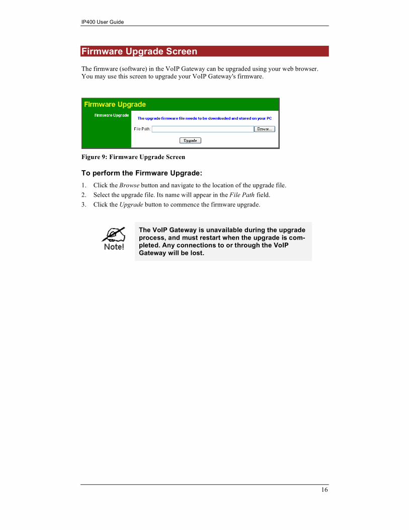
Firmware Upgrade Screen
The firmware (software) in the VoIP Gateway can be upgraded using your web browser.
You may use this screen to upgrade your VoIP Gateway's firmware.
Figure 9: Firmware Upgrade Screen
To perform the Firmware Upgrade:
1. Click the Browse button and navigate to the location of the upgrade file.
2. Select the upgrade file. Its name will appear in the File Path field.
3. Click the Upgrade button to commence the firmware upgrade.
The VoIP Gateway is unavailable during the upgrade process, and must restart when the upgrade is com-pleted. Any connections to or through the VoIP Gateway will be lost.

Setup
17
Reboot Screen
This page allows you to restart (reboot) the VoIP Gateway.
Figure 10: Reboot Screen
Data - Reboot Screen
Button
Restart System Click this button to restart the VoIP Gateway. All connections to or
through the VoIP Gateway will be lost.

IP400 User Guide
18
Gateway Screen
This screen displays the status of the VoIP Gateway.
Figure 11: Gateway Screen
Data - Gateway Screen
Gateway Information
Firmware Version The version of the current firmware installed.
MAC Address This shows the MAC Address for the VoIP Gateway
Current Time It displays the current date and time of the system.
Internet Connection
IP Address The IP Address of the VoIP Gateway.
IP Subnet Mask The Subnet Mask for the IP Address above.
Gateway IP Address The IP Address of the router.
Primary DNS The IP Address of the Primary DNS server.
Secondary DNS The IP Address of the Secondary DNS server.
Hook Status This indicates the status on the telephone line. ON-Hook
indicates the receiver is "on-the-hook", while OFF-Hook
indicates the receiver is "off-the-hook".
Battery Level The voltage level of each telephone line.

Setup
19
VoIP Screen
This screen displays the phone numbers and the status of the SIP registration.
Figure 12: VoIP Status Screen
Data - VoIP Status Screen
Line Status
Telephone Number The telephone number associated with this line.
Registration Status This shows the status of the connection to the SIP Server.

IP400 User Guide
20
Set Log Level Screen
The Logs record various types of activity on the VoIP Gateway. Use the Set Log Level
screen to configure this feature.
Figure 13: Set Log Level Screen
Data - Set Log Level Screen
Event Types
Telephony Telephony events will be logged
SIP Events related to SIP server are logged.
DSP Events related to the DSP will be logged.
Dial Plan Dial Plan events are logged
Others Other operations (not covered by the selections above) will be logged.
Log Level
Off Suppress logging of the event.
Low Log all events.
Mid Log events which are of middle significance.
High Log most significant event only.

Setup
21
Event Logs Screen
This screen displays the event logs of the VoIP Gateway.
Figure 14: Event Logs Screen
Data - Event Logs Screen
Event Logs
Event Logs Current log data is displayed in this panel.
Refresh Screen Click this button to update the messages shown on screen.
Clear Log Delete all data currently in the Log. This will make it easier to read
new messages.

22
Appendix A
Troubleshooting
This Appendix covers the most likely problems and their solutions.
Overview
This chapter covers some common problems that may be encountered while using the VoIP
Gateway and some possible solutions to them. If you follow the suggested steps and the
VoIP Gateway still does not function properly, contact your dealer for further advice.
General Problems
Problem 1: Can't connect to the VoIP Gateway to configure it.
Solution: Check the following:
• The VoIP Gateway is properly installed, LAN connections are OK,
and it is powered ON.
• Ensure that your PC and the VoIP Gateway are on the same network
segment. (If you don't have a router, this must be the case.)
• If your PC is set to "Obtain an IP Address automatically" (DHCP
client), restart it.
• If your PC uses a Fixed (Static) IP address, ensure that it is using an IP
Address within the range 192.168.0.1 to 192.168.0.254 and thus com-
patible with the VoIP Gateway's default IP Address of 192.168.0.250.
Also, the Network Mask should be set to 255.255.255.0 to match the
VoIP Gateway.
In Windows, you can check these settings by using Control Panel-
Network to check the Properties for the TCP/IP protocol.
• If you are using more than one gateway you may have to clear the
cache for the gateways IP address.
1. Go to Start > Run
2. Type “cmd” and press enter
3. On the command line type “ARP –d 192.168.0.250”
press enter (if using a different IP than substitute that portion of the
command).
Problem 2: Can't connect to the VoIP Gateway, the four Line LED indicators
flash simultaneously for 3 seconds and are off instantly.
Solution: The flash memory device that stores the firmware was damaged. It is likely
the latest firmware upgrade process was not completed successfully.
You’ll need to return the unit.
Problem 3: I am using DHCP, and don’t know the IP address that the VoIP Gate-
way obtained from DHCP server.
Solution: There is a Windows-based utility on the CD ROM named ScanIP.exe. This
utility can detect the IP address of the VoIP Gateway. To detect the IP
A

Troubleshooting
23
address of the VoIP Gateway, do the following steps:
1. Insert the supplied CD-ROM into your drive. Run ScanIP.exe in the
root folder. A pop-up window will be shown on the PC.
2. Click the SCAN button.
3. The utility will detect the presence of the VoIP Gateway and if the
VoIP Gateway is detected, it will display the MAC address, IP ad-
dress, subnet mask and other information in the table.
4. Click the Exit button to close the utility.

24
Appendix B
Specifications
VoIP Gateway
Model IP400
Dimensions 176mm(W) * 115mm(D) * 36mm(H)
Operating Temperature 0° C to 40° C
Storage Temperature -10° C to 70° C
VoIP Signaling Protocol Session Initiation Protocol (SIP)
Voice Codecs G.711, G.729AB, G.726
Ethernet Interface: 1 * 10/100BaseT (RJ45) for LAN
Line Interface 4 * RJ11, loop start FXO ports
LEDs 7
Power Adapter 5 V DC/2A External
B