IP Telephony Endpoints - Cisco Telephony Endpoints ... (Based on Cisco Unified Communications...
52
CHAPTER 20-1 Cisco Unified Communications SRND (Based on Cisco Unified Communications Manager 5.x) OL-10030-08 20 IP Telephony Endpoints Last revised on: September 27, 2007 This chapter summarizes various types of IP Telephony endpoints along with their features and QoS recommendations. The IP Telephony endpoints can be categorized into the following major types: • Analog Gateways, page 20-2 • Cisco Unified IP Phones, page 20-6 • Software-Based Endpoints, page 20-10 • Wireless Endpoints, page 20-13 • Cisco IP Conference Station, page 20-19 • Video Endpoints, page 20-20 • Third-Party SIP IP Phones, page 20-25 The sections listed above provide detailed information about each endpoint type. In addition, the section on QoS Recommendations, page 20-25, lists generic QoS configurations, and the Endpoint Features Summary, page 20-37, lists all the endpoint features. The following list summarizes high-level recommendations for selecting IP Telephony endpoints: • For low-density analog connections, use the Cisco Analog Telephone Adapter (ATA) or low-density analog interface module. • For medium to high-density analog connections, use the high-density analog interface module, Cisco Communication Media Module (CMM) with 24-FXS port adapter, Catalyst 6500 24-FXS analog interface module, Cisco VG224, or Cisco VG248. • For telephony users with limited call features who generate small amounts of traffic, use the Cisco Unified IP Phones 7902G, 7905G, 7906G, 7911G, 7912G, or 7912G-A. • For transaction-type telephony users who generate a medium amount of traffic, use Cisco Unified IP Phones 7940G, 7941G, or 7941G-GE. • For managers and administrative assistants who generate medium to heavy telephony traffic, use Cisco Unified IP Phones 7960G, 7961G, or 7961G-GE. • For executives with extensive call features who generate high amounts of telephony traffic, use Cisco Unified IP Phones 7970G or 7971G-GE. • For mobile workers and telecommuters, use Cisco IP Communicator. • For users who need a mobile IP phone, use the Cisco Unified Wireless IP Phone 7920.
-
Upload
nguyentuyen -
Category
Documents
-
view
238 -
download
1
Transcript of IP Telephony Endpoints - Cisco Telephony Endpoints ... (Based on Cisco Unified Communications...

Cisco Unified Communications SRND (BasOL-10030-08
C H A P T E R 20
IP Telephony EndpointsLast revised on: September 27, 2007
This chapter summarizes various types of IP Telephony endpoints along with their features and QoS recommendations. The IP Telephony endpoints can be categorized into the following major types:
• Analog Gateways, page 20-2
• Cisco Unified IP Phones, page 20-6
• Software-Based Endpoints, page 20-10
• Wireless Endpoints, page 20-13
• Cisco IP Conference Station, page 20-19
• Video Endpoints, page 20-20
• Third-Party SIP IP Phones, page 20-25
The sections listed above provide detailed information about each endpoint type. In addition, the section on QoS Recommendations, page 20-25, lists generic QoS configurations, and the Endpoint Features Summary, page 20-37, lists all the endpoint features.
The following list summarizes high-level recommendations for selecting IP Telephony endpoints:
• For low-density analog connections, use the Cisco Analog Telephone Adapter (ATA) or low-density analog interface module.
• For medium to high-density analog connections, use the high-density analog interface module, Cisco Communication Media Module (CMM) with 24-FXS port adapter, Catalyst 6500 24-FXS analog interface module, Cisco VG224, or Cisco VG248.
• For telephony users with limited call features who generate small amounts of traffic, use the Cisco Unified IP Phones 7902G, 7905G, 7906G, 7911G, 7912G, or 7912G-A.
• For transaction-type telephony users who generate a medium amount of traffic, use Cisco Unified IP Phones 7940G, 7941G, or 7941G-GE.
• For managers and administrative assistants who generate medium to heavy telephony traffic, use Cisco Unified IP Phones 7960G, 7961G, or 7961G-GE.
• For executives with extensive call features who generate high amounts of telephony traffic, use Cisco Unified IP Phones 7970G or 7971G-GE.
• For mobile workers and telecommuters, use Cisco IP Communicator.
• For users who need a mobile IP phone, use the Cisco Unified Wireless IP Phone 7920.
20-1ed on Cisco Unified Communications Manager 5.x)
Chapter 20 IP Telephony EndpointsAnalog Gateways
• For making video calls, use Cisco Unified Video Advantage associated with a Cisco Unified IP Phone or Cisco IP Communicator, the Cisco IP Video Phone 7985G, or Sony and Tandberg SCCP endpoints.
• For accessing voice, video, document sharing, and presence information from a single integrated interface, use Cisco Unified Personal Communicator.
• For formal conferencing environments, use the Cisco Unified IP Conference Station 7936.
Analog GatewaysAnalog gateways include router-based analog interface modules, Cisco Communication Media Module (CMM) with 24-FXS port adapter, Catalyst 6500 24-FXS analog interface module, Cisco VG224, Cisco VG248, and Cisco Analog Telephone Adaptor (ATA) 186 and 188. An analog gateway is usually used to connect analog devices, such as fax machines, modems, TDD/TTYs, and analog phones, to the VoIP network so that the analog signal can be packetized and transmitted over the IP network.
Analog Interface ModuleCisco router-based analog interface modules include low-density interface modules (NM-1V, NM-2V, NM-HD-1V, NM-HD-2V, NM-HD-2VE, NM-HDV2, NM-HDV2-1T1/E1, and NM-HDV2-2T1/E1) and high-density interface modules (NM-HDA-4FXS and EVM-HD-8FXS/DID). Cisco analog interface modules connect the PSTN and other legacy telephony equipment, including PBXs, analog telephones, fax machines, and key systems, to Cisco multiservice access routers. Cisco analog interface modules are best suited for connecting low- to high-density analog devices to the IP network with limited call features.
Low-Density Analog Interface Module
The low-density analog interface modules include the NM-1V, NM-2V, NM-HD-1V, NM-HD-2V, NM-HD-2VE, NM-HDV2, NM-HDV2-1T1/E1, and NM-HDV2-2T1/E1. The NM-1V and NM-2V contain one or two interface cards (VIC). The interface cards include: two-port FXS VIC (VIC-2FXS); two-port FXO VIC (VIC-2FXO, VIC-2FXO-M1/M2/M3, and VIC-2FXO-EU); two-port Direct Inward Dial VIC (VIC-2DID); two-port E&M VIC (VIC-2E/M); two-port Centralized Automated Message Accounting VIC (VIC-2CAMA); and two-port BRI VIC (VIC-2BRI-S/T-TE and VIC-2BRI-NT/TE). The NM-1V and NM-2V can serve up to two and four FXS connections, respectively.
Note The NM-1V and NM-2V are not supported on the Cisco 2800 and 3800 Series platforms. On the Cisco 2800 and 3800 Series platforms, the voice interface cards are supported in the on-board High-Speed WIC slots, including the VIC-2DID, VIC4-FXS/DID, VIC2-2FXO, VIC-2-4FXO, VIC2-2FXS, VIC2-2E/M, and VIC2-2BRI-NT/TE.
The NM-HD-1V and NM-HD-2V contain one and two VICs, respectively. The NM-HD-2VE contains two VICs or two voice/WAN interface cards (VWIC), or a combination of one VIC and one VWIC. The NM-HD-1V, NM-HD-2V, and NM-HD-2VE can serve up to 4, 8, and 8 FXS or FXO connections, respectively. The NM-HDV2, NM-HDV2-1T1/E1, and NM-HDV2-2T1/E1 can be fitted with either digital T1/E1 or analog/BRI voice interface cards, with up to 4 FXS or FXO connections. The difference among these three interface modules is that the NM-HDV2-1T1/E1 has one built-in T1/E1 port while the NM-HDV2-2T1/E1 has two built-in T1/E1 ports.
20-2Cisco Unified Communications SRND (Based on Cisco Unified Communications Manager 5.x)
OL-10030-08

Chapter 20 IP Telephony EndpointsAnalog Gateways
The voice interface cards include: 2-port and 4-port FXS VICs (VIC2-2FXS and VIC-4FXS/DID); 2-port and 4-port FXO VICs (VIC2-2FXO and VIC2-4FXO); 2-port Direct Inward Dial VIC (VIC-2DID); 2-port E&M VIC (VIC2-2E/M); and 2-port BRI VIC (VIC2-2BRI-NT/TE). The voice/WAN interface cards include: 1-port and 2-port RJ-48 multiflex trunk (MFT) T1/E1 VWICs for both voice and WAN connections (VWIC-1MFT-T1, VWIC-2MFT-T1, VWIC-2MFT-T1-DI, VWIC-1MFT-E1, VWIC-2MFT-E1, VWIC-2MFT-E1-DI, VWIC-1MFT-G703, VWIC-2MFT-G703, VWIC2-1MFT-T1/E1, VWIC2-2MFT-T1/E1, VWIC2-1MFT-G703, and VWIC2-2MFT-G703). The G.703 interface cards are primarily for data connectivity but can in some cases be configured to support voice applications.
High-Density Analog Interface Module
The high-density analog interface module includes the NM-HDA-4FXS and EVM-HD-8FXS/DID. The NM-HDA-4FXS has four on-board FXS ports and room for two expansion modules from the following options:
• EM-HDA-8FXS: An 8-port FXS interface card
• EM-HDA-4FXO/EM2-HDA-4FXO: A 4-port FXO interface card
The NM-HDA-4FXS provides up to 12 analog ports (4 FXS and 8 FXO) with four built-in FXS ports and two EM-HDA-4FXO or EM2-HDA-4FXO extension modules, or 16 analog ports (12 FXS and 4 FXO) with four built-in FXS ports and one EM-HDA-8FXS, and one EM-HDA-4FXO or EM2-HDA-4FXO extension module. A configuration using two 8-port FXS extension modules is not supported. The NM-HDA also has a connector for a daughter module (DSP-HDA-16) that provides additional DSP resources to serve an additional 8 high-complexity calls or 16 medium-complexity calls.
Note The EM2-HDA-4FXO supports the same density and features as the EM-HDA-FXO, but it provides enhanced features including longer loop length support of up to 15,000 feet and improved performance under poor line conditions when used in ground-start signaling mode.
The EVM-HD-8FXS/DID provides eight individual ports on the baseboard module and can be configured for FXS or DID signaling. In addition, the EVM-HD-8FXS/DID has room for two expansion modules from the following options:
• EM-HDA-8FXS: An 8-port FXS interface card
• EM-HDA-6FXO: A 6-port FXO interface card
• EM-HDA-3FXS/4FXO: A 3-port FXS and 4-port FXO interface card
• EM-4BRI-NT/TE: A 4-port BRI interface card
These extension modules can be used in any combination and provide for configurations of up to 24 FXS ports per EVM-HD-8FXS/DID.
20-3Cisco Unified Communications SRND (Based on Cisco Unified Communications Manager 5.x)
OL-10030-08

Chapter 20 IP Telephony EndpointsAnalog Gateways
Supported Platforms and Cisco IOS Requirements for Analog Interface Modules
The supported platforms for Cisco analog interface modules are the Cisco 2600, 2800, 3600, 3700, and 3800 Series. Table 20-1 lists the maximum number of interface modules supported per platform, and Table 20-2 lists the minimum Cisco IOS software version required.
Table 20-1 Maximum Number of Analog Interface Modules Supported per Platform
Platform
Maximum Number of Interface Modules Supported
NM-1V, -2VNM-HDA-4FXS EVM-HD
NM-HD-1V, -2V, -2VE
NM-HDV2, -1T1/E1, -2T1/E1
Cisco 2600XM 1 1 No 1 1
Cisco 2691 1 1 No 1 1
Cisco 3640 3 3 No 3 No
Cisco 3660 6 6 No 6 No
Cisco 3725 2 2 No 2 2
Cisco 3745 4 4 No 4 4
Cisco 2811 No 1 1 1 1
Cisco 2821 No 1 1 1 1
Cisco 2851 No 1 1 1 1
Cisco 3825 No 2 1 2 2
Cisco 3845 No 4 2 4 4
Table 20-2 Minimum Cisco IOS Requirements for Analog Interface Modules
Platform
Minimum Cisco IOS Software Release Required
NM-1V, -2V NM-HDA-4FXS EVM-HDNM-HD-1V, -2V, -2VE
NM-HDV2, -1T1/E1, -2T1/E1
Cisco 2600XM 12.2(8)T 12.2(8)T No 12.3.4T 12.3(7)T
Cisco 2691 12.2(8)T 12.2(8)T No 12.3.4T 12.3(7)T
Cisco 3640 12.0(1)T or later
12.2(8)T or later
No 12.3.4T No
Cisco 3660 12.0(1)T or later
12.2(8)T or later
No 12.3.4T No
Cisco 3725 12.2(8)T or later
12.2(8)T No 12.3.4T 12.3(7)T
Cisco 3745 12.2(8)T or later
12.2(8)T No 12.3.4T 12.3(7)T
Cisco 2811 No 12.3.8T4 12.3.8T4 12.3.8T4 12.3.8T4
Cisco 2821 No 12.3.8T4 12.3.8T4 12.3.8T4 12.3.8T4
Cisco 2851 No 12.3.8T4 12.3.8T4 12.3.8T4 12.3.8T4
Cisco 3825 No 12.3(11)T 12.3(11)T 12.3(11)T 12.3(11)T
Cisco 3845 No 12.3(11)T 12.3(11)T 12.3(11)T 12.3(11)T
20-4Cisco Unified Communications SRND (Based on Cisco Unified Communications Manager 5.x)
OL-10030-08

Chapter 20 IP Telephony EndpointsAnalog Gateways
Cisco Communication Media Module (CMM)The Cisco CMM is a line card that provides high-density analog, T1, and E1 gateway connections for Catalyst 6000 and Cisco 7600 Series switches. The Cisco CMM can serve up to 72 FXS connections. The CMM operates as either an MGCP or H.323 gateway, and it provides Survivable Remote Site Telephony (SRST) service for up to 480 IP phones.
Cisco CMM can contain the following interface port adapters: 24-port FXS analog port adapter (WS-SVC-CMM-24FXS), 6-port T1 interface port adapter (WS-SVC-CMM-6T1), 6-port E1 interface port adapter (WS-SVC-CMM-6E1), and conference/transcoding port adapter (WS-SVC-CMM-ACT). Table 20-3 lists the minimum software requirements for the compatible port adapters.
WS-X6624-FXS Analog Interface ModuleThe Cisco WS-X6624-FXS analog interface module is an MGCP-based device for connecting high-density analog devices to the IP telephony network, and it provides 24 analog ports.
Note The WS-X6624 FXS analog interface module is no longer available for sale.
Cisco VG224 GatewayThe Cisco VG224 analog gateway is a Cisco IOS high-density 24-port gateway for connecting analog devices to the IP Telephony network. In Cisco IOS Release 12.4(2)T and later, the Cisco VG224 can act as an Session Initiation Protocol (SIP), Skinny Client Control Protocol (SCCP), Media Gateway Control Protocol (MGCP), or H.323 endpoint with Cisco Unified Communications Manager (Unified CM) and re-home to a Survivable Remote Site Telephone (SRST) router in failover scenarios. The Cisco VG224 supports Cisco Unified CM Release 3.1 and later. The Cisco VG224 also supports modem pass-through, modem relay, fax pass-through, and fax relay.
Cisco VG248 GatewayThe Cisco VG248 is a high-density, 48 port, Skinny Client Control Protocol (SCCP) gateway for connecting analog devices such as analog phones, fax machines, modems and speakerphones to an enterprise Cisco Unified CM (Release 3.1 and later) and voice network. The Cisco VG248 also supports Unified CM integration with legacy voicemail systems and PBXs compatible with Simplified Message Desk Interface (SMDI), NEC Message Center Interface (MCI), or Ericsson voicemail protocols. The Cisco VG248 supports failover to Survivable Remote Site Telephone (SRST).
Table 20-3 Software Requirements for CMM Port Adapters
WS-SVC-CMM-24FXS WS-SVC-CMM-6T1 WS-SVC-CMM-6E1 WS-SVC-CMM-ACT
Cisco IOS Release 12.3(8)XY 12.3(8)XY 12.3(8)XY 12.3(8)XY
CatOS Release 7.3(1) 7.3(1) 7.3(1) 7.6.8
Native IOS Release 12.1(15)E 12.1(14)E 12.1(13)E 12.1(13)E
Maximum number of port adapters per CMM
3 3 3 4
20-5Cisco Unified Communications SRND (Based on Cisco Unified Communications Manager 5.x)
OL-10030-08

Chapter 20 IP Telephony EndpointsCisco Unified IP Phones
Cisco ATA 186 and 188The Cisco Analog Telephone Adaptor (ATA) 186 or 188 can connect two analog devices to the IP telephony network, and it is the best suited for low-density analog devices connecting to the IP network.
The difference between the Cisco ATA 186 and 188 is that the former has only one 10 Base-T Ethernet connection while the later has an integrated Ethernet switch providing two 10/100 Base-T Ethernet connections for itself and a co-located PC or other Ethernet-based device. The Cisco ATA 186 and 188 can be configured in any of the following ways:
• Cisco ATA web configuration page
• Cisco ATA voice configuration menu
• Configuration file downloaded from the TFTP server
The SCCP-based ATA behaves like an SCCP IP phone. The Cisco ATA 186 or 188 can be configured as a SIP client that registers with the SIP proxy server to make phone calls with another endpoint. The Cisco ATA 186 or 188 can act as either a user agent client (UAC) when it initiates SIP requests or as a user agent server (UAS) when it responds to requests. Cisco Unified CM 5.x does not have native SIP support for the Cisco ATA 186 or 188.
Cisco Unified IP PhonesThe Cisco IP phone portfolio includes basic IP phones, business IP phones, manager IP Phones, and executive IP phones.
Cisco Basic IP PhonesThe Cisco basic IP phone is best suited for low-traffic users with limited call features and budget requirements. The basic IP phones include Cisco Unified IP Phone 7902G, 7905G, 7906G, 7911G, and 7912G.
Cisco Unified IP Phone 7902G
The Cisco Unified IP Phone 7902G supports a single line and it has a single 10-Base-T Ethernet port on the back of the phone. The Cisco Unified IP Phone 7902G does not have any liquid crystal display (LCD) screen. The Cisco Unified IP Phone 7902G supports SCCP but has no support for SIP.
Cisco Unified IP Phone 7905G
The Cisco Unified IP Phone 7905G supports a single line and it has a single 10-Base-T Ethernet port on the back of the phone. The speaker operates in one-way listen mode only. The Cisco Unified IP Phone 7905G supports SCCP and SIP; however, the features and user interface (UI) are not consistent across the two call signaling protocols.
Cisco Unified IP Phone 7906G
The Cisco Unified IP Phone 7906G supports a single line and it has a single 10/100 BaseT Ethernet port on the back of the phone. The speaker operates in one-way listen mode only. Power is supplied via IEEE 802.3af, Cisco inline power, or local power through a power adaptor (CP-PWR-CUBE-3). The Cisco
20-6Cisco Unified Communications SRND (Based on Cisco Unified Communications Manager 5.x)
OL-10030-08

Chapter 20 IP Telephony EndpointsCisco Unified IP Phones
Unified IP Phone 7906G supports SCCP and SIP and is one of the phones included in the enhanced architecture of Cisco Desktop IP Phones. This architecture provides for feature and UI consistency across the Cisco Desktop IP Phones regardless of call signaling protocol. The end-user experience for a supported feature will behave consistently whether using SCCP or SIP call control signaling.
Cisco Unified IP Phone 7911G
The Cisco Unified IP Phone 7911G supports only a single line and it has two 10/100 BaseT Ethernet connections. The speaker operates in one-way listen mode only. Power is supplied via IEEE 802.3af, Cisco inline power, or local power through a power adaptor (CP-PWR-CUBE-3). The Cisco Unified IP Phone 7911G supports SCCP and SIP and is one of the phones included in the enhanced architecture of Cisco Desktop IP Phones. This architecture provides for feature and UI consistency across the Cisco Desktop IP Phones regardless of call signaling protocol. The end-user experience for a supported feature will behave consistently whether using SCCP or SIP call control signaling.
Cisco Unified IP Phone 7912G
The Cisco Unified IP Phone 7912G supports only a single line and it has two 10/100 BaseT Ethernet connections. The speaker operates in one-way listen mode only. The Cisco Unified IP Phone 7912G supports SCCP and SIP; however, the features and user interface (UI) are not consistent across the two call signaling protocols.
Note The initial version of the Cisco Unified IP Phone 7912G is no longer available for sale. The initial version of the Cisco Unified IP Phone 7912G is now replaced by the Cisco Unified IP Phone 7912G-A, which offers identical features but has an enhanced Ethernet switch.
Cisco Business IP PhonesThe Cisco business IP phone is best suited for the transaction-type worker with medium telephony traffic use and extensive call features, such as speakers, headset, and so forth. The business IP phones include Cisco Unified IP Phone 7940G, 7941G, and 7941G-GE.
Cisco Unified IP Phone 7940G
The Cisco Unified IP Phone 7940G can have up to two directory numbers and includes two 10/100 BaseT Ethernet connections. The Cisco Unified IP Phone 7940G supports SCCP and SIP; however, the features and user interface (UI) are not consistent across the two call signaling protocols. For example, the Cisco Unified IP Phone 7940G using SCCP has full security capability, whereas SIP does not have any previously implemented security features. The Cisco Unified IP Phone 7940G using SCCP is compatible with the Cisco Unified Video Advantage video-enabled endpoint to make video calls, whereas the Cisco Unified IP Phone 7940G using SIP has no video support. For a complete list of supported features, see the Endpoint Features Summary, page 20-37.
20-7Cisco Unified Communications SRND (Based on Cisco Unified Communications Manager 5.x)
OL-10030-08

Chapter 20 IP Telephony EndpointsCisco Unified IP Phones
Cisco Unified IP Phone 7941G
The Cisco Unified IP Phone 7941G can have up to two directory numbers and includes two 10/100 BaseT Ethernet connections. The Cisco Unified IP Phone 7941G supports SCCP and SIP and is included in the enhanced architecture of Cisco Unified IP Phones. This architecture provides for feature and UI consistency across the Cisco IP phones regardless of call signaling protocol. The end-user experience for a supported feature will behave consistently whether using SCCP or SIP call control signaling.
There are a few features that are not supported with SIP that are supported with SCCP. For example, the Cisco Unified IP Phone 7941G using SCCP is compatible with the Cisco Unified Video Advantage video-enabled endpoint to make video calls, whereas SIP has no video support. The Cisco Unified IP Phone 7941G using SCCP supports Tone on Hold, whereas SIP has no Tone on Hold support. For a complete list of supported features, see the Endpoint Features Summary, page 20-37.
This phone includes a higher-resolution, 4-bit grayscale display for enhancing feature usage and Extensible Markup Language (XML) applications, as well as for enabling support for double-byte languages. Power is supplied via IEEE 802.3af, Cisco inline power, or local power through a power adaptor (CP-PWR-CUBE-3).
Cisco Unified IP Phone 7941G-GE
The Cisco Unified IP Phone 7941G-GE can have up to two directory numbers and is the equivalent of the Cisco Unified IP Phone 7941G with the exception that it includes two 10/100/1000 BaseT Ethernet connections. The addition of gigabit throughput capability allows for high bit-rate and bandwidth-intensive applications on a co-located PC.
Cisco Manager IP PhonesThe Cisco manager IP phone is best suited for managers and administrative assistants with medium to heavy telephony traffic use and extensive call features such as speakers, headset, and so forth. The business IP phones include Cisco Unified IP Phone 7960G, 7961G, and 7961G-GE.
Cisco Unified IP Phone 7960G
The Cisco Unified IP Phone 7960G can have up to six directory numbers and includes two 10/100 BaseT Ethernet connections. The Cisco Unified IP Phone 7960G supports SCCP and SIP; however, the features and user interface (UI) are not consistent across the two call signaling protocols. For example, the Cisco Unified IP Phone 7960G using SCCP has full security capability, whereas SIP does not have any previously implemented security features. The Cisco Unified IP Phone 7960G using SCCP is compatible with the Cisco Unified Video Advantage video-enabled endpoint to make video calls, whereas the Cisco Unified IP Phone 7960G using SIP has no video support. The Cisco Unified IP Phone 7960G using SCCP supports the Cisco Unified IP Phone Expansion Module 7914, whereas SIP has no support for the expansion module. For a complete list of supported features, see the Endpoint Features Summary, page 20-37.
20-8Cisco Unified Communications SRND (Based on Cisco Unified Communications Manager 5.x)
OL-10030-08

Chapter 20 IP Telephony EndpointsCisco Unified IP Phones
Cisco Unified IP Phone 7961G
The Cisco Unified IP Phone 7961G can have up to six directory numbers and includes two 10/100 BaseT Ethernet connections. The Cisco Unified IP Phone 7961G supports SCCP and SIP and is included in the enhanced architecture of the Cisco Unified IP Phones. This architecture provides for feature and UI consistency across the Cisco IP phones regardless of call signaling protocol. The end-user experience for a supported feature will behave consistently whether using SCCP or SIP call control signaling.
There are a few features that are not supported with SIP that are supported with SCCP. For example, the Cisco Unified IP Phone 7961G using SCCP is compatible with the Cisco Unified Video Advantage video-enabled endpoint to make video calls, whereas SIP has no video support. The Cisco Unified IP Phone 7961G using SCCP supports Tone on Hold, whereas SIP has no Tone on Hold support. The Cisco Unified IP Phone 7961G using SCCP supports the Cisco Unified IP Phone Expansion Module 7914, whereas SIP has no support for the expansion module. For a complete list of supported features, see the Endpoint Features Summary, page 20-37.
This phone includes a higher-resolution, 4-bit grayscale display for enhancing feature usage and Extensible Markup Language (XML) applications, as well as for enabling support for double-byte languages. Power is supplied via IEEE 802.3af, Cisco inline power, or local power through a power adaptor (CP-PWR-CUBE-3).
Cisco Unified IP Phone 7961G-GE
The Cisco Unified IP Phone 7961G-GE can have up to six directory numbers and is the equivalent of the Cisco Unified IP Phone 7961G with the exception that it includes two 10/100/1000 BaseT Ethernet connections. The addition of gigabit throughput capability allows for high bit-rate and bandwidth-intensive applications on a co-located PC.
Cisco Executive IP PhonesThe Cisco executive IP phone is best suited for the executive high-traffic user with extensive call features. The executive IP phones include the Cisco Unified IP Phone 7970G and 7971G-GE.
Cisco Unified IP Phone 7970G
The Cisco Unified IP Phone 7970G can have up to eight directory numbers, has a high-resolution color touch screen, and has more access keys on the phone compared to other Cisco Unified IP Phones. The Cisco Unified IP Phone 7970G supports both SCCP and SIP and is included in the enhanced architecture of Cisco Desktop IP Phones. This architecture provides for feature and UI consistency across the Cisco Desktop IP Phones regardless of call signaling protocol. The end-user experience for a supported feature will behave consistently whether using SCCP or SIP call control signaling.
There are a few features that are not supported with SIP that are supported with SCCP. For example, the Cisco Unified IP Phone 7970G using SCCP is compatible with the Cisco Unified Video Advantage video-enabled endpoint to make video calls, whereas SIP has no video support. The Cisco Unified IP Phone 7970G using SCCP supports Tone on Hold, whereas SIP has no Tone on Hold support. The Cisco Unified IP Phone 7970G using SCCP supports the Cisco Unified IP Phone Expansion Module 7914, whereas SIP has no support for the expansion module. For a complete list of supported features, see the Endpoint Features Summary, page 20-37.
The Cisco Unified IP Phone 7970G includes a high-resolution color touch screen for enhancing feature usage and Extensible Markup Language (XML) applications, as well as for enabling support for double-byte languages. Power is supplied via IEEE 802.3af, Cisco inline power, or local power through
20-9Cisco Unified Communications SRND (Based on Cisco Unified Communications Manager 5.x)
OL-10030-08

Chapter 20 IP Telephony EndpointsSoftware-Based Endpoints
a power adaptor (CP-PWR-CUBE-3). For the Cisco Unified IP Phone 7970G to have full display brightness, the external power adaptor (CP-PWR-CUBE-3) must be used for both Cisco inline power and IEEE 802.3af Power over Ethernet (PoE).
Cisco 7971G-GE
The Cisco Unified IP Phone 7971G-GE can have up to eight directory numbers and is the equivalent of the Cisco Unified IP Phone 7970G with the exception that it includes two 10/100/1000 BaseT Ethernet connections. The addition of gigabit throughput capability allows for high bit-rate and bandwidth-intensive applications on a co-located PC.
Note In addition to using the inline power from the access switch or local wall power, a Cisco Unified IP Phone can also be supplied power by a power injector, Promax. Promax connects Cisco Unified IP Phones to Cisco switches that do not support online power or to non-Cisco switches. Promax is compatible with all Cisco Unified IP Phones, and it supports both Cisco PoE and IEEE 802.3af PoE. It has two 10/100/1000 Base-T Ethernet ports. One Ethernet port connects to the switch access port and the other connects to the Cisco Unified IP Phone.
Cisco Unified IP Phone Expansion Module 7914The Cisco Unified IP Phone Expansion Module 7914 is for administrative assistants and others who need to determine the status of a number of lines beyond the current line capability of the phone.
The Cisco Unified IP Phone Expansion Module 7914 extends the capability of the Cisco Unified IP Phone 7960G, 7961G, 7961G-GE, 7970G, or 7971G-GE with additional buttons and an LCD. The Cisco Unified IP Phone Expansion Module 7914 provides 14 buttons per module, and the Cisco Unified IP Phones 796xG and 797xG can support up to two Cisco Unified IP Phone Expansion Modules. If the IP phone uses Cisco inline power or IEEE802.3af PoE, then the Cisco Unified IP Phone Expansion Module 7914 requires the use of an external power adaptor (CP-PWR-CUBE-3).
Software-Based EndpointsSoftware-based endpoints include Cisco Unified Personal Communicator and Cisco IP Communicator. A software-based endpoint is an application installed on a client PC, and it registers with (and is controlled by) Unified CM.
Cisco Unified Personal CommunicatorCisco Unified Personal Communicator is a software application based on Microsoft Windows or Macintosh, and it integrates a wide variety of communications applications and services into a single desktop application to help people communicate effectively. It lets users access a variety of powerful communications tools, including voice, video, call management, presence, and web conferencing. The integrated applications include Cisco Unified Communications Manager (Unified CM), Cisco Unified Presence, Cisco Unity Connection, Cisco Unified MeetingPlace Express, and the Lightweight Directory Access Protocol (LDAP) version 3 (v3) server. This section summarizes the following design considerations that apply when using Cisco Unified Personal Communicator with Unified CM:
• Maximum Cisco Unified Personal Communicator Configuration Limits, page 20-11
20-10Cisco Unified Communications SRND (Based on Cisco Unified Communications Manager 5.x)
OL-10030-08

Chapter 20 IP Telephony EndpointsSoftware-Based Endpoints
• Codec Selection, page 20-11
• Call Admission Control, page 20-11
For more information on Cisco Unified Personal Communicator, see the chapter on Cisco Unified Presence, page 21-1.
Maximum Cisco Unified Personal Communicator Configuration Limits
Regardless of the device limits allowed per server, there are maximum limits on the number CTI devices you can configure in Unified CM. The CTI device limits as they apply to Cisco Unified Personal Communicator are as follows:
• Maximum of 800 Cisco Unified Personal Communicators per Cisco Media Convergence Server (MCS) 7825 or 7835; maximum of 3,200 Cisco Unified Personal Communicators per cluster of MCS 7825 or 7835 servers.
• Maximum of 2,500 Cisco Unified Personal Communicators per Cisco Media Convergence Server (MCS) 7845; maximum of 10,000 Cisco Unified Personal Communicator s per cluster of MCS 7845 servers.
The following assumptions apply to the preceding maximum Cisco Unified Personal Communicator limits:
• Each Cisco Unified Personal Communicator is processing an estimated six or fewer busy hour call attempts (BHCA).
• No other CTI applications requiring CTI devices are configured in the Unified CM cluster.
Codec Selection
Audio codec support on Cisco Unified Personal Communicator includes G.711 and G.729a, and its video codec support includes H.263 and H.264. The codec selection can be done by configuring the region in which Cisco Unified Personal Communicator is located. Cisco recommends G.729a low-bandwidth codec configurations for calls across the WAN.
Call Admission Control
Call admission control ensures that there is enough bandwidth available to process IP phone calls over the network. While there are several mechanisms for implementing call admission control, Cisco Unified Personal Communicator uses the locations mechanism configured in Unified CM for centralized call processing deployments, or it uses the RSVP mechanism in non-centralized call processing deployments. For more information on call admission control with Unified CM locations, see the chapter on Call Admission Control, page 9-1.
Call admission control based on locations or RSVP is effective in managing call bandwidth as long as the Cisco Unified Personal Communicator is mobile within only a single Unified CM location. However, call admission control becomes problematic if the Cisco Unified Personal Communicator is moved between Unified CM locations. For more information on mobility, refer toDevice Mobility and Unified CM, page 20-18.
20-11Cisco Unified Communications SRND (Based on Cisco Unified Communications Manager 5.x)
OL-10030-08

Chapter 20 IP Telephony EndpointsSoftware-Based Endpoints
Cisco IP CommunicatorCisco IP Communicator is a Microsoft Windows-based application that endows computers with the functionality of IP phones. This application enables high-quality voice calls on the road, in the office, or from wherever users can access the corporate network. It is an ideal solution for remote users and telecommuters. Cisco IP Communicator is easy to deploy and features some of the latest technology and advancements available with IP communications today. This section summarizes the following design considerations that apply when using Cisco IP Communicator with Unified CM:
• Maximum IP Communicator Configuration Limits, page 20-12
• Codec Selection, page 20-12
• Call Admission Control, page 20-13
Maximum IP Communicator Configuration Limits
Because Cisco IP Communicator is a standalone device that supports both SCCP and SIP, the design guidelines for IP phones in the various IP Telephony deployment models still hold true for the Cisco IP Communicator. Refer to the chapter on Deployment Models, page 2-1, for details.
The end-user experience for a supported feature is the same whether using SCCP or SIP call control signaling. There are a few features that are not supported with SIP that are supported with SCCP. For example, Cisco IP Communicator using SCCP is compatible with the Cisco Unified Video Advantage video-enabled endpoint for making video calls, whereas SIP has no video support. In addition, Cisco IP Communicator using SCCP supports Tone on Hold, whereas SIP has no Tone on Hold support. For a complete list of supported features, see the Endpoint Features Summary, page 20-37.
Codec Selection
The Cisco IP Communicator supports G.711 and G.729a codecs. The codec selection can be done by configuring the region in which Cisco IP Communicator is located. Cisco recommends G.729a low-bandwidth codec configurations in deployments with telecommuters connecting their Cisco IP Communicator across the WAN. The Cisco IP Communicator also has a low-bandwidth codec overriding capability in a G.711 region, which can be enabled by checking the Optimize for Low Bandwidth option in the Audio setting window (see Figure 20-1). In this case, the Cisco IP Communicator will use a G.729 codec to set up a call with another phone in the same region. Cisco IP Communicator can make video calls when it is used together with Cisco Unified Video Advantage. For more information on the video codec support of Cisco Unified Video Advantage, see Video Telephony Endpoints, page 20-34.
20-12Cisco Unified Communications SRND (Based on Cisco Unified Communications Manager 5.x)
OL-10030-08

Chapter 20 IP Telephony EndpointsWireless Endpoints
Figure 20-1 Cisco IP Communicator Audio Setting
Call Admission Control
Call admission control ensures that there is enough bandwidth available to process IP phone calls over the network. While there are several mechanisms for implementing call admission control, the Cisco IP Communicator uses the locations mechanism configured in Unified CM for centralized call processing deployments or it uses the RSVP mechanism in non-centralized call processing deployments. Refer to the chapter on Call Admission Control, page 9-1, for more information on call admission control with Unified CM locations.
Locations and RSVP-based call admission control are effective in managing call bandwidth as long as the Cisco IP Communicator is mobile within only a single Unified CM location. However, call admission control becomes problematic if the Cisco IP Communicator is moved between Unified CM locations. For more information on mobility, refer to Device Mobility and Unified CM, page 20-18.
Wireless EndpointsCisco wireless endpoints use a wireless LAN (WLAN) infrastructure via wireless access points (APs) to provide telephony functionality and features. This type of endpoint is ideal for environments with the need for mobile users within an area where traditional wired phones are undesirable or problematic. (Refer to Wireless LAN Infrastructure, page 3-60, for more information about wireless network design.)
Cisco offers the following two Voice over WLAN (VoWLAN) IP phones:
• Cisco Unified Wireless IP Phone 7920
• Cisco Unified Wireless IP Phone 7921G
20-13Cisco Unified Communications SRND (Based on Cisco Unified Communications Manager 5.x)
OL-10030-08

Chapter 20 IP Telephony EndpointsWireless Endpoints
Both are hardware-based phones with built-in radio antenna. The Cisco Unified Wireless IP Phone 7920 enables 802.11b wireless LAN connectivity to the network, while the Cisco Unified Wireless IP Phone 7921G enables 802.11b, 802.11g, or 802.11a connectivity to the network. These phones register with Unified CM using Skinny Client Control Protocol (SCCP), just like the hardware-based phones and Cisco IP Communicator. For more information about these phones, refer to the appropriate phone documentation available at
http://www.cisco.com
Site SurveyBefore deploying the Cisco Unified Wireless IP Phones, you must perform a complete site survey to determine the appropriate number and location of APs required to provide radio frequency (RF) coverage. Your site survey should take into consideration which types of antennas will provide the best coverage, as well as where sources of RF interference might exist. A site survey requires the use of the Site Survey tool on the Cisco Unified Wireless IP Phones (accessed via Menu > Network Config > Site Survey on the 7920 and via Settings > Status > Site Survey on the 7921G) and the Aironet Client Utility Site Survey Tool used with a Cisco Aironet NIC card on a laptop or PC. Additional third-party tools can also be used for site surveys; however, Cisco highly recommends that you conduct a final site survey using the Cisco Unified Wireless IP Phone 7920 and 7921G because each endpoint or client radio can behave differently depending on antenna sensitivity and survey application limitations.
AuthenticationTo connect to the wireless network, the Cisco Unified Wireless IP Phone must first use one of the following authentication methods to associate and communicate with the AP:
• Extensible Authentication Protocol-Flexible Authentication via Secure Tunneling (EAP-FAST)
This method allows the Cisco Unified Wireless IP Phone to be authenticated to the AP via 802.1X with a user name and password once a secure authenticated tunnel is established between the client and an EAP-compliant Remote Authentication, Authorization, and Accounting server via Protected Access Credential (PAC). Upon authentication, traffic to and from the wireless device is encrypted using TKIP or WEP. Using the 802.1X authentication method and the PAC authenticated tunnel exchange requires an EAP-compliant Remote Authentication Dial-In User Service (RADIUS) authentication server such as the Cisco Secure Access Control Server (ACS), which provides access to a user database.
• Wi-Fi Protected Access (WPA)
This method allows the Cisco Unified Wireless IP Phone to be authenticated to the AP via 802.1X with a user name and password. Upon authentication, traffic to and from the wireless device is encrypted using Temporal Key Integrity Protocol (TKIP). Using the 802.1X authentication method requires an EAP-compliant Remote Authentication Dial-In User Service (RADIUS) authentication server such as the Cisco Secure Access Control Server (ACS), which provides access to a user database.
• Wi-Fi Protected Access 2 (WPA2)
This method is the 802.11i enhanced version of WPA, which uses Advanced Encryption Standards (AES) rather than TKIP for encrypting traffic to and from the wireless device. This method is supported only on the Cisco Unified Wireless IP Phone 7921G.
20-14Cisco Unified Communications SRND (Based on Cisco Unified Communications Manager 5.x)
OL-10030-08

Chapter 20 IP Telephony EndpointsWireless Endpoints
• Wi-Fi Protected Access Pre-Shared Key (WPA-PSK)
This method allows the Cisco Unified Wireless IP Phone to be authenticated to the AP via the configuration of a shared key on the Cisco Unified Wireless IP Phone and the AP. Upon authentication, traffic to and from the wireless device is encrypted using TKIP. This method of authentication is not recommended for enterprise deployments.
• Wi-Fi Protected Access 2 Pre-Shared Key (WPA2-PSK)
This method is the 802.11i enhanced version of WPA-PSK, which uses AES rather than TKIP for encrypting traffic to and from the wireless device. This method is supported only on the Cisco Unified Wireless IP Phone 7921G.
• Cisco Centralized Key Management (Cisco CKM)
This method allows the Cisco Unified Wireless IP Phone to be authenticated to the AP via 802.1x with a user name and password. Upon authentication, traffic to and from the wireless device is encrypted using either WEP 128 or TKIP. The 802.1X authentication method requires an EAP-compliant RADIUS authentication server such as the Cisco ACS, which provides access to a user database for the initial authentication request. Subsequent authentication requests are validated via the wireless domain service (WDS) at the AP, which shortens re-authentication times and ensures fast, secure roaming.
• Cisco LEAP
This method allows the Cisco Unified Wireless IP Phone and AP to be authenticated mutually based on a user name and password. Upon authentication, the dynamic key is generated and used for encrypting traffic between the Cisco Unified Wireless IP Phone and the AP. A LEAP-compliant Radius authentication server, such as the Cisco Secure Access Control Server (ACS), is required to provide access to the user database.
• Shared Key
This method involves the configuration of static 10 (40-bit) or 26 (128-bit) character keys on the Cisco Unified Wireless IP Phone and the AP. This method is AP-based authentication in which access to the network is gained if the device has a matching key.
• Open Authentication
This method requires no exchange of identifying information between the Cisco Wireless IP Phone and the AP. Cisco does not recommend this method because it provides no secure exchange of voice or signaling, and it allows any rouge device to associate to the AP.
CapacityThe capacity of each AP depends on a number of factors including the AP radio types, associated client radio types, enabled data rates, and channel utilization.
Given an 802.11b-only AP with 802.11b clients and a data rate of 11 Mbps, the AP can support a maximum of seven active G.711 voice streams or eight G.729 streams. If these numbers are exceeded, poor quality can result due to dropped or delayed voice packets or dropped calls. AP rates set lower than 11 Mbps will result in lower call capacity per AP.
When using 802.11a at a data rate of 54 Mbps, the maximum number of active voice streams increases to between 14 and 18 per AP.
For 802.11g environments with a data rate of 54 Mbps, in theory the maximum number of active voice streams also increases to between 14 and 18 per AP. However, because most 802.11g environments are mixed and include 802.11b clients (and therefore 11 Mbps data rates) as well as 802.11g clients, capacity is typically significantly lower with a maximum of 8 to 12 active voice streams per AP.
20-15Cisco Unified Communications SRND (Based on Cisco Unified Communications Manager 5.x)
OL-10030-08

Chapter 20 IP Telephony EndpointsWireless Endpoints
Regardless of 802.11 radio type, call capacity can be diminished significantly if there is heavy channel utilization due to data traffic.
For additional information about call capacity, radio types, and data rates, refer to the VoWLAN design recommendations in the latest version of the Enterprise Mobility Design Guide, available at
http://www.cisco.com/go/designzone
Note A call between two phones associated to the same AP counts as two active voice streams.
Based on these active call capacity limits, and using Erlang ratios, you can calculate the number of Cisco Unified Wireless IP Phones that each AP can support. For example, given an 802.11b AP with 802.11b clients and a typical user-to-call capacity ratio of 3:1, a single AP can support 21 to 24 Cisco Unified Wireless IP Phones, depending on whether the codec used is G.711 or G.729. As another example, given an 802.11a AP with an 802.11a client at a data rate of 54 Mbps and user-to-call capacity ratio of 3:1, a single AP can support 42 to 54 Cisco Unified Wireless IP Phone 7921Gs. However, these numbers do not take into consideration the possibility that other Cisco Unified Wireless IP Phones could roam to the AP, so a lower number of phones per AP might be more realistic.
These capacities are based on voice activity detection (VAD) being disabled and a packetization sample size of 20 milliseconds (ms). VAD is a mechanism for conserving bandwidth by not sending RTP packets while no speech is occurring during the call. However, enabling or disabling VAD is a global cluster-wide configuration parameter on Unified CM. (It is referred to as Silence Suppression in Unified CM.) Thus, if VAD is enabled for the Cisco Unified Wireless IP Phone 7920, then it will be enabled for all devices in the Unified CM cluster. Cisco recommends leaving VAD (Silence Suppression) disabled to provide better overall voice quality.
At a sampling rate of 20 ms, a voice call will generate 50 packets per second (pps) in either direction. Cisco recommends setting the sample rate to 20 ms for almost all cases. By using a larger sample size (for example, 30 or 40 ms), you can increase the number of simultaneous calls per AP, but a larger end-to-end delay will result. In addition, the percentage of acceptable voice packet loss within a wireless environment decreases dramatically with a larger sample size because more of the conversation is missing when a packet is lost. For more information about voice sampling size, see Bandwidth Provisioning, page 3-45.
Phone ConfigurationFor information on configuring the Cisco Unified Wireless IP Phones, refer to the Cisco Unified Wireless IP Phone 7920 Administration Guide and the Cisco Unified Wireless IP Phone 7921G Administration Guide, available at
http://www.cisco.com
Roaming Cisco Unified Wireless IP Phones are able to roam at Layer 2 (within the same VLAN or subnet) and still maintain an active call. Layer 2 roaming occurs in the following situations:
• During the initial boot-up of the Cisco Unified Wireless IP Phones, the phone roams to a new AP for the first time.
20-16Cisco Unified Communications SRND (Based on Cisco Unified Communications Manager 5.x)
OL-10030-08

Chapter 20 IP Telephony EndpointsWireless Endpoints
• If the Cisco Unified Wireless IP Phone receives no beacons or responses from the AP to which it is currently associated, the phone assumes that the current AP is unavailable and it attempts to roam and associate with a new AP.
• The Cisco Unified Wireless IP Phone maintains a list of eligible AP roam targets. If conditions change on the current AP, the phone consults the list of available AP roam targets. If one of the roam targets is determined to be a better choice, then the phone attempts to roam to the new AP.
• If the configured SSID or authentication type on the Cisco Unified Wireless IP Phone is changed, the phone must roam to re-associate with an AP.
In trying to determine eligible AP roam targets for roaming, the wireless IP phone uses the following variables to determine the best AP to associate with:
• Relative Signal Strength Indicator (RSSI)
Used by the wireless IP phone to determine the signal strength and quality of available APs within an RF coverage area. The phone will attempt to associate with the AP that has the highest RSSI value and matching authentication/encryption type.
• QoS Basic Service Set (QBSS)
Enables the AP to communicate channel utilization information to the wireless phone. The phone will use the QBSS value to determine if it should attempt to roam to another AP, because APs with high channel utilization might not be able to handle VoIP traffic effectively.
• Wi-Fi Multimedia Traffic Specification (WMM TSPEC)
WMM TSPEC is an 802.11e QoS mechanism that assists wireless IP phone roaming by enabling the phone to request bandwidth and priority treatment via a TSPEC indication while roaming to determine if the new AP can handle the phones bandwidth needs based on current utilization. TSPEC is supported only by the Cisco Unified Wireless IP Phone 7921G.
When devices roam at Layer 3, they move from one AP to another AP across native VLAN boundaries. When the WLAN network infrastructure consists of autonomous APs, the Cisco Catalyst 6500 Series Wireless LAN Services Module (WLSM) allows the Cisco Unified Wireless IP Phone to keep its IP address and roam at Layer 3 while still maintaining an active call. Seamless Layer 3 roaming occurs only when the client is roaming within the same mobility group. For details about the Cisco WLSM and Layer 3 roaming, refer to the Cisco WLSM product documentation available at
http://www.cisco.com
Seamless Layer 3 roaming for clients across a lightweight access point infrastructure is accomplished by WLAN controllers that use dynamic interface tunneling. Cisco Unified Wireless IP Phones that roam across WLAN controllers and VLANS can keep their IP address when using the same SSID and therefore can maintain an active call.
With stronger authentication methods such as WPA and EAP, the number of information exchanges increases and causes more delay during roaming. To avoid additional delays, use Cisco Centralized Key Management (Cisco CKM) to manage authentication. With Cisco CKM, whether at Layer 2 or Layer 3, roaming can occur without any perceptible delay. Cisco CKM also takes some of the load off the Access Control Server (ACS) by reducing the number of authentication requests that must be sent to the ACS.
Note In dual-band WLANs (those with both 2.4 GHz and 5 GHz bands), it is possible to roam between 802.11b/g and 802.11a with the same SSID, provided the client is capable of supporting both bands. However, this can cause gaps in the voice path. In order to avoid these gaps, use only one band for voice communications.
20-17Cisco Unified Communications SRND (Based on Cisco Unified Communications Manager 5.x)
OL-10030-08

Chapter 20 IP Telephony EndpointsWireless Endpoints
AP Call Admission ControlCall admission control mechanisms in Unified CM or in a gatekeeper can control WAN bandwidth utilization and provide QoS for existing calls, but both mechanisms are applied at the beginning of a call. For calls between static devices, this type of call admission control is sufficient. However, for a call between two mobile wireless devices such as Cisco Unified Wireless IP Phones, there must also be a call admission control mechanism at the AP level because these wireless devices may roam from one AP to another.
Cisco APs and wireless voice clients have two mechanisms that are used for call admission control:
• QoS Basic Service Set (QBSS)
QBSS is the beacon information element that enables the AP to communicate channel utilization information to the wireless IP phone. As previously mentioned, this QBSS value helps the phone determine whether it should roam to another AP. A lower QBSS value indicates that the AP is a good candidate to roam to, while a higher QBSS value indicates that the phone should not roam to this AP.
While this QBSS information is useful, it is not a true call admission control mechanism because it does not guarantee that calls will retain proper QoS or that there is enough bandwidth to handle the call. When a Cisco Unified Wireless IP Phone is associated to an AP with a high QBSS, the AP will prevent a call from being initiated or received by rejecting the call setup and sending a Network Busy message to the initiating phone. However, once a call is set up between a wireless IP phone and another endpoint, the phone may roam and associate with an AP with a high QBSS, thus resulting in oversubscription of the available bandwidth on that AP.
• Wi-Fi Multimedia Traffic Specification (WMM TSPEC)
WMM TSPEC is the QoS mechanism that enables WLAN clients to provide an indication of their bandwidth and QoS requirements so that APs can react to those requirements. When a client is preparing to make a call, it sends an Add Traffic Stream (ADDTS) message to the AP with which it is associated, indicating TSPEC. The AP can then accept or reject the ADDTS request based on whether bandwidth and priority treatment are available. If the call is rejected, the phone will receive a Network Busy message. When roaming, mid-call clients supporting TSPEC will send a ADDTS message to the new AP as part of the association process to ensure that there is available bandwidth for priority treatment. If there is not enough bandwidth, the roam can be load-balanced to a neighboring AP if one is available.
Cisco Unified Wireless IP Phone 7920s support only QBSS, so this is the only mechanism that can be used for call admission control with these devices. However, the Cisco Unified Wireless IP Phone 7921Gs support both QBSS and TSPEC. (TSPEC takes precedence over QBSS.) Therefore call admission control with the Cisco Unified Wireless IP Phone 7921G, when using TSPEC, is more accurate and eliminates the possibility of priority bandwidth oversubscription on the AP.
Device Mobility and Unified CMWhen a wireless IP phone becomes a mobile device and moves from one location to another, the following potential problems could arise:
• Inaccurate bandwidth accounting for Unified CM locations-based call admission control
When a wireless IP phone roams from one location to another, there is currently no dynamic mechanism in Unified CM to update the phone’s location for purposes of call admission control. As a result, bandwidth can be subtracted from locations that are not actually using the bandwidth, and bandwidth can be used in other locations but not taken into account by the locations-based call admission control, thus causing oversubscription of the WAN bandwidth.
20-18Cisco Unified Communications SRND (Based on Cisco Unified Communications Manager 5.x)
OL-10030-08

Chapter 20 IP Telephony EndpointsCisco IP Conference Station
• Inappropriate codec selection
When a wireless IP phone roams from one location to another, there is currently no dynamic mechanism in Unified CM to update its region and/or device pool for purposes of determining codec type. As a result, the wrong codec can be used throughout the telephony network.
• Inappropriate PSTN gateway selection
When a wireless IP phone roams from one location to another, there is currently no dynamic mechanism in Unified CM to update the dial plan to specify the local PSTN gateway. As a result, the wireless IP phone might use a remote PSTN gateway for PSTN access. If the wireless IP phone places an emergency 911 call through this remote PSTN gateway, the emergency services will be directed to the location of the remote PSTN gateway and not to the location of the wireless IP phone that initiated the call.
Note If Cisco Emergency Responder (ER) is deployed, then 911 calls will be routed to the local PSTN gateway and to the appropriate public safety answering point (PSAP). However, call admission control will still be unaware of the bandwidth used by this call, and the wrong codec might be selected.
To prevent these device mobility problems, you must manually reconfigure the following parameters of the wireless IP phone in Unified CM each time the phone is moved from one physical location to another:
• Call admission control location
• Device pool and region
• Calling search space
These parameters must be adjusted appropriately for each location to which the wireless IP phone moves. Other parameters might have to be reconfigured manually if advanced or non-standard features are required. For example, the media resource group list (for conferencing, transcoding, and music-on-hold resources) and the automated alternate routing (AAR) calling search space and group (if AAR is configured) must be reconfigured to ensure that local media resources are used and that automatic alternate call routing is appropriate for each location.
Note that these device mobility issues come into play not only for the wireless IP phone but also for any device that moves between locations, including Cisco IP SoftPhone, Cisco IP Communicator, and any Cisco hardware IP phone that is physically moved from one place to another.
Finally, these device mobility issues affect both centralized and distributed call processing deployments.
Cisco IP Conference StationThe Cisco IP Conference Station combines conference room speaker-phone technology with Cisco IP Communications technology. The Cisco IP Conference Station is best suited for use in conferencing environments providing 360-degree room coverage.
The Cisco Unified IP Conference Station 7936 has an external speaker and three built-in microphones. The Cisco Unified IP Conference Station 7936 requires Cisco Unified CM Release 3.3(3) SR3 or later. The Cisco Unified IP Conference Station 7936 also features a pixel-based LCD display with backlighting, and optional extension microphones can be connected to it for extended microphone coverage in larger rooms.
20-19Cisco Unified Communications SRND (Based on Cisco Unified Communications Manager 5.x)
OL-10030-08

Chapter 20 IP Telephony EndpointsVideo Endpoints
Video EndpointsCisco Unified CM 5.x supports the following types of video-enabled endpoints:
• Cisco Unified Video Advantage associated with a Cisco Unified IP Phone 7911, 7940, 7941, 7960, 7961, 7970, or 7971, or with Cisco IP Communicator, running Skinny Client Control Protocol (SCCP)
• Cisco IP Video Phone 7985
• Tandberg 2000 MXP, 1500 MXP, 1000 MXP, 770 MXP, 550 MXP, T-1000, and T-550 models running SCCP
• Sony PCS-1, PCS-TL30, and PCS-TL50 models running SCCP
• H.323 and SIP clients (Polycom, Sony, PictureTel, EyeBeam, Tandberg, VCON, VTEL, Microsoft NetMeeting, and others)
SCCP Video EndpointsSCCP video endpoints register directly with Unified CM and download their configurations via Trivial File Transfer Protocol (TFTP). They support many features and supplementary services, including hold, transfer, conference, park, pickup and group pickup, music on hold, shared line appearances, mappable softkeys, call forwarding (busy, no answer, and unconditional), and much more.
Cisco Unified Video Advantage
Cisco Unified Video Advantage is a Windows-based application and USB camera that you can install on a Windows 2000 or Windows XP personal computer. When the PC is physically connected to the PC port on a Cisco Unified IP Phone 7911, 7940, 7941, 7960, 7961, 7970, or 7971 running the Skinny Client Control Protocol, the Cisco Unified Video Advantage application "associates" with the phone, thus enabling users to operate their phones as they always have but now with the added benefit of video. In Cisco Unified Video Advantage Release 2.0, this association can also be to Cisco IP Communicator running SCCP on the same PC.
The system administrator can control which IP Phones allow this association to take place by toggling the Video Capabilities: Enabled/Disabled setting on the IP Phone configuration page in Unified CM Administration. When this feature is enabled, an icon representing a camera appears in the bottom right-hand corner of the IP Phone display. By default, Cisco Unified Video Advantage is disabled. You can also use the Bulk Administration Tool to modify this setting on many phones at once. Note that the PC Port: Enabled/Disabled setting must also be enabled for Cisco Unified Video Advantage to work with a hardware IP Phone; however, the PC Access to Voice VLAN setting does not have to be enabled.
To achieve the association with a hardware IP Phone, Cisco Unified Video Advantage installs a Cisco Discovery Protocol (CDP) driver onto the Ethernet interface of the PC. CDP enables the PC and the hardware IP Phone to discover each other automatically, which means that the user does not have to configure anything on the PC or the hardware IP Phone in order for Cisco Unified Video Advantage to work. The user can, therefore, plug the PC into any hardware IP Phone that is video-enabled and automatically associate with it. (See Figure 20-2.)
Cisco Unified Video Advantage 2.0 does not rely on CDP to discover the presence of Cisco IP Communicator running SCCP on the same PC. Instead, it listens for a private Windows message sent from the Cisco IP Communicator process. If Cisco IP Communicator is discovered, the association process works exactly as it does for a hardware IP phone. (See Figure 20-3.)
20-20Cisco Unified Communications SRND (Based on Cisco Unified Communications Manager 5.x)
OL-10030-08

Chapter 20 IP Telephony EndpointsVideo Endpoints
Note When you install Cisco Unified Video Advantage, the CDP packet drivers install on all Ethernet interfaces of the PC. If you add a new network interface card (NIC) or replace an old NIC with a new one, you must reinstall Cisco Unified Video Advantage so that the CDP drivers also install on the new NIC.
Figure 20-2 Cisco Unified Video Advantage Operational Overview
Figure 20-2 illustrates the following events:
1. The IP Phone and PC exchange Cisco Discovery Protocol (CDP) messages. The phone begins listening for PC association packets on TCP port 4224 from the IP address of its CDP neighbor.
2. The PC initiates association messages to the phone over TCP/IP. Association packets are routed up to the Layer-3 boundary between VLANs. Firewalls and/or access control lists (ACLs) must permit TCP port 4224.
3. The phone acts as an SCCP proxy between Cisco Unified Video Advantage and Unified CM. Unified CM tells the phone to open video channels for the call, and the phone proxies those messages to the PC.
4. The phone sends/receives audio, and the PC sends/receives video. Both audio and video traffic are marked DSCP AF41. Video traffic uses UDP port 5445.
1194
53
802.1Q/p
CDP1
“I want to associate with you”
“Open video channel” “Open video channel”
Video packets
Audio packets
2
3 3
4
4
M
Si IPCampus
Phone VLAN = 110 PC VLAN = 10
IP Phone: 10.70.110.100
VT Advantage171.70.10.100
20-21Cisco Unified Communications SRND (Based on Cisco Unified Communications Manager 5.x)
OL-10030-08

Chapter 20 IP Telephony EndpointsVideo Endpoints
Figure 20-3 Cisco IP Communicator Associating with Cisco Unified Video Advantage
Figure 20-3 illustrates the following events:
1. Cisco IP Communicator sends a private Windows message to Cisco Unified Video Advantage. The message includes the IP address of Cisco IP Communicator and the port number for CAST messages.
2. Cisco Unified Video Advantage initiates CAST messages to Cisco IP Communicator over TCP/IP. CAST messages do not leave the PC because it is a connected address.
3. Cisco IP Communicator acts as an SCCP proxy between Cisco Unified Video Advantage and Unified CM. Unified CM tells IP Communicator to open video channels for the call, and IP Communicator proxies those messages to Cisco Unified Video Advantage via CAST protocol.
4. Cisco IP Communicator sends/receives audio, and Cisco Unified Video Advantage sends/receives video. Both audio and video traffic are marked DSCP AF41. Video traffic uses UDP port 5445.
When a call is made using Cisco Unified Video Advantage, the audio is handled by the IP Phone while the video is handled by the PC. There is no synchronization mechanism between the two devices, so QoS is essential to minimize jitter, latency, fragmented packets, and out-of-order packets.
When using a hardware IP Phone, the phone resides in the voice VLAN while the PC resides in the data VLAN, which means that there must be a Layer-3 routing path between the voice and data VLANs in order for the association to occur. If there are access control lists (ACLs) or firewalls between these VLANs, they must be configured to permit the association protocol (which uses TCP port 4224 in both directions) to pass. When using Cisco IP Communicator, this communication happens internal to the PC, and there are no Layer-3 boundaries to cross.
Cisco Unified Video Advantage supports Differentiated Services Code Point (DSCP) traffic classifications. Unified CM specifies the DSCP value in the SCCP messages it sends to the phone. When the IP Phone makes an audio-only call, it marks its SCCP control traffic as DSCP CS3 and its audio RTP media traffic as DSCP EF. However, when the IP Phone makes a video call, it marks its SCCP control traffic as DSCP CS3 and its audio RTP media traffic as DSCP AF41, and the Cisco Unified Video Advantage application marks its video RTP media traffic as DSCP AF41 as well. Both the IP Phone and the Cisco Unified Video Advantage application mark their "association" protocol messages as DSCP CS3 because it is considered to be signaling traffic and is grouped with all other signaling traffic such as SCCP.
1903
16
Campus
M
1Si
PC VLAN = 10
PC Address: 10.70.110.100
Cisco IPCommunicator
Private Windows Message
Cisco UnifiedVideo Advantage
3
4
2 “CAST: I want to associate with you”
“SCCP: Open video channel” “CAST: Open video channel”
Video packets
Audio packets
20-22Cisco Unified Communications SRND (Based on Cisco Unified Communications Manager 5.x)
OL-10030-08

Chapter 20 IP Telephony EndpointsVideo Endpoints
Note Cisco Unified CM Release 4.0 added security features to the Cisco Unified IP Phone 7970 and 7971 to enable it to use Transport Layer Security (TLS) and Secure RTP (SRTP) to authenticate and encrypt signaling and audio media traffic. The association protocol does not use this authentication or encryption, nor are the video RTP media streams encrypted. However, the SCCP signaling and the audio RTP media streams are encrypted if they are so configured.
Note Do not set the voice VLAN equal to the data VLAN because doing so can cause issues with connectivity.
Cisco Unified Video Advantage, like any other application that runs on a PC, does have an impact on system performance, which you should take into consideration. Cisco Unified Video Advantage 1.0 supports two types of video codecs: H.263 and the Cisco VT Camera Wideband Video Codec. Cisco Unified Video Advantage 2.0 also supports two types of codecs: H.263 and H.264. The Cisco VT Camera Wideband Video Codec places the least demand on the PC but the most demand on the network. H.263 places a lower demand on the network but a higher demand on the PC. Finally, H.264 places the least demand on the network but the highest demand on the PC. Therefore, if your network has plenty of available bandwidth, you can use the Cisco VT Camera Wideband Video Codec and save on PC CPU and memory resources.
The H.263 and H.264 codec supports a range of speeds up to 1.5 Mbps. In summary, customers must balance PC performance with network utilization when deploying Cisco Unified Video Advantage.
System Requirements
For detailed PC requirements, refer to the Cisco Unified Video Advantage Data Sheet, available at
http://www.cisco.com/en/US/products/sw/voicesw/ps5662/products_data_sheet0900aecd8044de04.html
Cisco IP Video Phone 7985G
The Cisco IP Video Phone 7985G is a personal desktop video phone. Unlike Cisco Unified Video Advantage, which is an application that runs on a PC, the Cisco IP Video Phone 7985G is a standalone phone with integrated video features. The phone has an 8.4 inch color LCD screen and an embedded video camera for making video calls. The phone supports up to eight line appearances, has two 10/100 BaseT Ethernet connections, and has buttons for Directories, Messages, Settings, and Services. Like other Cisco Unified IP Phones, the Cisco IP Video Phone 7985G uses CDP to learn VLAN and CoS information from the attached switch to use in 802.1p/q markings.
Codecs Supported by Cisco Unified Video Advantage and Cisco IP Video Phone 7985G
Table 20-4 lists the codecs supported by Cisco Unified Video Advantage and Cisco IP Video Phone 7985G
Table 20-4 Codecs Supported by Cisco Unified Video Advantage and Cisco IP Video Phone
7985G
Codec or Feature Cisco Unified Video Advantage Cisco IP Video Phone 7985G
H.264 Yes in Release 2.0 Yes
H.263 Yes Yes
20-23Cisco Unified Communications SRND (Based on Cisco Unified Communications Manager 5.x)
OL-10030-08

Chapter 20 IP Telephony EndpointsVideo Endpoints
Third-Party SCCP Video Endpoints
Two manufacturers of video endpoints, Sony and Tandberg, currently have products that support the Cisco Skinny Client Control Protocol (SCCP). SCCP on both the Sony and Tandberg endpoints is modeled after SCCP on the Cisco Unified IP Phone 7940. Most features found on the Cisco Unified IP Phone 7940 user interface are also supported on the Sony endpoints as well as the Tandberg endpoints, including multiple line appearances, softkeys, and buttons for Directories, Messages, Settings, Services, and so forth. The Sony and Tandberg endpoints also support the Option 150 field in DHCP to discover the IP address of the TFTP server, and they download their configurations from the TFTP server. However, software upgrades of the Sony and Tandberg endpoints are not done via TFTP. Instead, the customer must manually upgrade each endpoint using tools provided by the vendor. (Tandberg uses an FTP method, while Sony uses FTP or a physical memory stick.) The Sony and Tandberg endpoints register with up to three Unified CM servers and will fail-over to its secondary or tertiary servers if its primary server becomes unreachable.
While the Sony and Tandberg endpoints support softkey functionality similar to that of the Cisco Unified IP Phone 7940 and 7960, the exact feature support differs between vendor and model. Check the manufacturers' documentation for supported features. Features that are currently known to be missing on some platforms include:
• Messages button
• Directories (placed calls, received calls, missed calls, and corporate directory)
• Settings and Services buttons
• Some XML services (such as Extension Mobility and Berbee's InformaCast)
Because the Sony and Tandberg endpoints use SCCP, dialing a video call from an endpoint is similar to dialing an audio call from a Cisco Unified IP Phone. If users are familiar with Cisco Unified IP Phones, they should also find the Sony and Tandberg endpoints very intuitive to use. The main difference in the user interface is that the Sony and Tandberg endpoints do not have a button keypad or a handset like those on a phone. Instead, the remote control is used to access features and to dial numbers on the Sony and Tandberg endpoints.
H.261 No Yes
G.711 Yes Yes
G.722 No Yes
G.722.1 No No
G.723.1 No No
G.728 No No
G.729 Yes Yes
Cisco Wideband Yes in Release 1.0 No
Maximum Bandwidth 7 Mbps for Release 1.0 and 1.5 Mbps for Release 2.0
768 kbps
Video Resolution CIF, QCIF NTSC: 4SIF, SIF
PAL: 4CIF, QCIF, SQCIF
Table 20-4 Codecs Supported by Cisco Unified Video Advantage and Cisco IP Video Phone
7985G (continued)
Codec or Feature Cisco Unified Video Advantage Cisco IP Video Phone 7985G
20-24Cisco Unified Communications SRND (Based on Cisco Unified Communications Manager 5.x)
OL-10030-08

Chapter 20 IP Telephony EndpointsThird-Party SIP IP Phones
Note Sony and Tandberg endpoints do not support the Cisco Discovery Protocol (CDP) or IEEE 802.Q/p. Therefore, you must manually configure the VLAN ID and Quality of Service trust boundary on the ethernet switch to which they are attached. (For more details, see Network Infrastructure, page 3-1.)
Codecs Supported by Sony and Tandberg SCCP Endpoints
Codec support for the third-party SCCP endpoints varies by vendor, model, and software version. Check the vendors' product documentation for the supported codecs.
Third-Party SIP IP PhonesThird-party phones have specific local features that are independent of the call control signaling protocol, such as features access buttons (fixed or variable). Basic SIP RFC support allows for certain desktop features to be the same as Cisco Unified IP Phones and also allows for interoperability of certain features. However, these third-party SIP phones do not provide the full feature functionality of Cisco Unified IP Phones.
Cisco is working with key third-party vendors who are part of the Cisco Technology Development Partner Program and who are developing solutions that leverage the new Unified CM and Cisco Unified Communications Manager Express (Unified CME) SIP capabilities. Vendors include IPCelerate (unified client for education space), RIM (Blackberry 7270 wireless LAN handsets) and IP blue (Softphone). Cisco has also worked with third-party vendor Grandstream to test their Grandstream GXP 2000 to ensure interoperability.
Cisco is also participating in an independent third party testing and interoperability verification process being offered by tekVizion. This independent service provided by tekVizion has been established to enable third-party vendors to test and verify the interoperability of their endpoints with Unified CM and Unified CME.
For more information on Cisco’s line-side SIP interoperability and third-party verification, visit http://www.cisco.com.
QoS RecommendationsThis sections provides the basic QoS guidelines and configurations for the Cisco Catalyst switches most commonly deployed with IP Telephony endpoints. For more details, refer to the Quality of Service design guide at
http://www.cisco.com/go/designzone
Cisco VG224 and VG248Analog gateways are trusted endpoints. For Cisco VG224 and VG248 gateways, configure the switch to trust the DSCP value of the VG248 packets. The following sections list the commands to configure the most common Cisco Catalyst switches for the Cisco VG224 and VG248 analog gateways.
Note In the following sections, vvlan_id is the voice VLAN ID and dvlan_id is the data VLAN ID.
20-25Cisco Unified Communications SRND (Based on Cisco Unified Communications Manager 5.x)
OL-10030-08

Chapter 20 IP Telephony EndpointsQoS Recommendations
Cisco 2950CAT2950(config)#interface interface-idCAT2950(config-if)#mls qos trust dscpCAT2950(config-if)#switchport mode accessCAT2950(config-if)#switchport access vlan vvlan_id
Note The mls qos trust dscp command is available only with Enhanced Image (EI).
Cisco 2970 or 3750CAT2970(config)#mls qosCAT2970(config)interface interface-idCAT2970(config-if)#mls qos trust dscpCAT2970(config-if)#switchport mode accessCAT2970(config-if)#switchport access vlan vvlan_id
Cisco 3550CAT3550(config)#mls qosCAT3550(config)interface interface-idCAT3550(config-if)#mls qos trust dscpCAT3550(config-if)#switchport mode accessCat3550(config-if)#switchport access vlan vvlan_id
Cisco 4500 with SUPIII, IV, or VCAT4500(config)#qosCAT4500(config)interface interface-idCAT4500(config-if)#qos trust dscpCAT4500(config-if)#switchport mode accessCAT4500(config-if)#switchport access vlan vvlan_id
Cisco 6500CAT6500>(enable)set qos enableCAT6500>(enable)set port qos 2/1 vlan-basedCAT6500>(enable)set vlan vvlan_id mod/portCAT6500>(enable)set port qos mod/port trust trust-dscp
Cisco ATA 186 and IP Conference StationBecause the Cisco Analog Telephone Adaptor (ATA) 186 and IP Conference Station are trusted endpoints, their QoS configurations are identical to those described in the section on Cisco VG224 and VG248, page 20-25.
Cisco ATA 188 and IP PhonesFor the Cisco Analog Telephone Adaptor (ATA) 188 and IP Phones, Cisco recommends segregating the voice VLAN from the data VLAN. For the Cisco ATA 186, 7902, 7905, 7906, 7910, and IP Conference Station, Cisco still recommends configuring voice and data VLAN segregation and an auxiliary voice VLAN. In this way, the same access-layer configurations can be used with different IP phone models and ATAs, and end-users can plug their IP phones or ATAs into different access ports on the switch and
20-26Cisco Unified Communications SRND (Based on Cisco Unified Communications Manager 5.x)
OL-10030-08

Chapter 20 IP Telephony EndpointsQoS Recommendations
get the same treatment. For the Cisco ATA 186, 7902, 7905, 7906, 7910, and IP Conference Stations, the command to override the CoS value of the frames from the attached PC has no effects because these devices do not have a PC connected to them.
The following sections list the configuration commands for IP phones on the most commonly deployed Cisco Catalyst switches.
Cisco 2950CAT2950(config)#CAT2950(config)#class-map VVLANCAT2950(config-cmap)# match access-group name VVLANCAT2950(config-cmap)#class-map VLANCAT2950(config-cmap)# match access-group name DVLANCAT2950(config-cmap)#exitCAT2950(config)#CAT2950(config)#policy-map IPPHONE-PCCAT2950(config-pmap)# class VVLANCAT2950(config-pmap-c0# set ip dscp 46CAT2950(config-pmap-c)# police 1000000 8192 exceed-action-dropCAT2950(config-pmap)# class DVLANCAT2950(config-pmap-c0# set ip dscp 0CAT2950(config-pmap-c)# police 5000000 8192 exceed-action-dropCAT2950(config-pmap-c)#exitCAT2950(config-pmap)#exitCAT2950(config)#CAT2950(config)#interface interface-idCAT2950(config-if)#mls qos trust device cisco-phoneCAT2950(config-if)#mls qos trust cosCAT2950(config-if)#switchport mode accessCAT2950(config-if)#switchport voice vlan vvlan_idCAT2950(config-if)#switchport access vlan dvlan_idCAT2950(config-if)#service-policy input IPPHONE-PCCAT2950(config-if)#exitCAT2950(config)#CAT2950(config)#ip access-list standard VVLANCAT2950(config-std-nacl)# permit voice_IP_subnet wild_card_maskCAT2950(config-std-nacl)#exitCAT2950(config)#ip access-list standard DVLANCAT2950(config-std-nacl)# permit data_IP_subnet wild_card_maskCAT2950(config-std-nacl)#end
Note The mls qos map cos-dscp command is available only with Enhanced Image (EI). With Standard Image (SI), this command is not available and the default CoS-to-DSCP mapping is as follows:
Cisco 2970, 3560, or 3750CAT2970(config)# mls qos map cos-dscp 0 8 16 24 34 46 48 56CAT2970(config)# mls qos map policed-dscp 0 24 to 8CAT2970(config)#CAT2970(config)#class-map match-all VVLAN-VOICECAT2970(config-cmap)# match access-group name VVLAN-VOICECAT2970(config-cmap)# CAT2970(config-cmap)#class-map match-all VVLAN-CALL-SIGNALINGCAT2970(config-cmap)# match access-group name VVLAN-CALL-SIGNALING
CoS Value 0 1 2 3 4 5 6 7
DSCP Value 0 8 16 24 32 40 48 56
20-27Cisco Unified Communications SRND (Based on Cisco Unified Communications Manager 5.x)
OL-10030-08

Chapter 20 IP Telephony EndpointsQoS Recommendations
CAT2970(config-cmap)# CAT2970(config-cmap)#class-map match-all VVLAN-ANYCAT2970(config-cmap)# match access-group name VVLAN-ANYCAT2970(config-cmap)# CAT2970(config-cmap)# policy-map IPPHONE-PCCAT2970(config-pmap)#class VVLAN-VOICECAT2970(config-pmap-c)# set ip dscp 46CAT2970(config-pmap-c)# police 128000 8000 exceed-action dropCAT2970(config-pmap-c)# class VVLAN-CALL-SIGNALINGCAT2970(config-pmap-c)# set ip dscp 24CAT2970(config-pmap-c)# police 32000 8000 exceed-action policed-dscp-transmitCAT2970(config-pmap-c)# class VVLAN-ANYCAT2970(config-pmap-c)# set ip dscp 0CAT2970(config-pmap-c)# police 32000 8000 exceed-action policed-dscp-transmitCAT2970(config-pmap-c)# class class-defaultCAT2970(config-pmap-c)# set ip dscp 0CAT2970(config-pmap-c)# police 5000000 8000 exceed-action policed-dscp-transmitCAT2970(config-pmap-c)# exitCAT2970(config-pmap)# exitCAT2970(config)#CAT2970(config)#CAT2970(config)#interface interface-idCAT2970(config-if)# switchport voice vlan vvlan_idCAT2970(config-if)# switchport access vlan dvlan_idCAT2970(config-if)# mls qos trust device cisco-phoneCAT2970(config-if)# service-policy input IPPHONE-PCCAT2970(config-if)# exitCAT2970(config)#CAT2970(confiig)#ip access list extended VVLAN-VOICECAT2970(config-ext-nacl)# permit udp Voice_IP_Subnet Subnet_Mask any range 16384 32767 dscp efCAT2970(config-ext-nacl)# exitCAT2970(config)#ip access list extended VVLAN-CALL-SIGNALINGCAT2970(config-ext-nacl)# permit tcp Voice_IP_Subnet Subnet_Mask any range 2000 2002 dscp cs3CAT2970(config-ext-nacl)# permit tcp Voice_IP_Subnet Subnet_Mask any range 2000 2002 dscpAf31CAT2970(config-ext-nacl)# permit udp Voice_IP_Subnet Subnet_Mask any eq 5060 dscp cs3CAT2970(config-ext-nacl)# permit tcp Voice_IP_Subnet Subnet_Mask any range 5060 5061 dscp cs3CAT2970(config-ext-nacl)# exitCAT2970(config)#ip access list extended VVLAN-ANYCAT2970(config-ext-nacl)# permit ip Voice_IP_Subnet Subnet_Mask anyCAT2970(config-ext-nacl)# endCAT2970#
Cisco 3550CAT3550(config)# mls qos map cos-dscp 0 8 16 24 34 46 48 56CAT3550(config)# mls qos map policed-dscp 0 24 26 46 to 8CAT3550(config)#class-map match-all VOICECAT3550(config-cmap)# match ip dscp 46CAT3550(config-cmap)#class-map match-any CALL SIGNALINGCAT3550(config-cmap)# match ip dscp 26CAT3550(config-cmap)# match ip dscp 24CAT3550(config-cmap)#CAT3550(config-cmap)#class-map match-all VVLAN-VOICECAT3550(config-cmap)# match vlan vvlan_idCAT3550(config-cmap)# match class-map VOICECAT3550(config-cmap)#CAT3550(config-cmap)#class-map match-all VVLAN-CALL-SIGNALINGCAT3550(config-cmap)# match vlan vvlan_idCAT3550(config-cmap)# match class-map CALL SIGNALING
20-28Cisco Unified Communications SRND (Based on Cisco Unified Communications Manager 5.x)
OL-10030-08

Chapter 20 IP Telephony EndpointsQoS Recommendations
CAT3550(config-cmap)#CAT3550(config-cmap)#class-map match-all ANYCAT3550(config-cmap)# match access-group name ACL_NameCAT3550(config-cmap)#CAT3550(config-cmap)# class-map match-all VVLAN-ANYCAT3550(config-cmap)# match vlan vvlan_idCAT3550(config-cmap)# match class-map ANYCAT3550(config-cmap)#CAT3550(config-cmap)#class-map match-all DVLAN-ANYCAT3550(config-cmap)# match vlan dvlan_idCAT3550(config-cmap)# match class-map ANYCAT3550(config-cmap)#CAT3550(config-cmap)#policy-map IPPHONE-PCCAT3550(config-pmap)# class VVLAN-VOICECAT3550(config-pmap-c)# set ip dscp 46CAT3550(config-pmap-c)# police 128000 8000 exceed-action dropCAT3550(config-pmap-c)#CAT3550(config-pmap-c)#class VVLAN-CALL-SIGNALINGCAT3550(config-pmap-c)# set ip dscp 24CAT3550(config-pmap-c)# police 32000 8000 exceed-action policed-dscp-transmitCAT3550(config-pmap-c)#CAT3550(config-pmap-c)#class VVLAN-ANYCAT3550(config-pmap-c)# set ip dscp 0CAT3550(config-pmap-c)# police 32000 8000 exceed-action policed-dscp-transmitCAT3550(config-pmap-c)#CAT3550(config-pmap-c)#class DVLAN-VOICECAT3550(config-pmap-c)# set ip dscp 0CAT3550(config-pmap-c)# police 5000000 8000 exceed-action policed-dscp-transmitCAT3550(config-pmap-c)#exitCAT3550(config-pmap)#exitCAT3550(config)#interface interface-idCAT3550(config-if)# switchport voice vlan vvlan_idCAT3550(config-if)# switchport access vlan dvlan_idCAT3550(config-if)# mls qos trust device cisco-phoneCAT3550(config-if)# service-policy input IPPHONE-PCCAT3550(config-if)# exitCAT3550(config)#CAT3550(confiig)#ip access list standard ACL_ANYCAT3550(config-std-nacl)# permit anyCAT3550(config-std-nacl)# endCAT3550#
Cisco 4500 with SUPIII, IV, or VCAT4500(config)# qos map cos 5 to dscp 46CAT4500(config)# qos map cos 0 24 26 46 to dscp 8CAT4500(config)#CAT4500(config)#class-map match-all VVLAN-VOICECAT4500(config-cmap)# match access-group name VVLAN-VOICECAT4500(config-cmap)# CAT4500(config-cmap)#class-map match-all VVLAN-CALL-SIGNALINGCAT4500(config-cmap)# match access-group name VVLAN-CALL-SIGNALINGCAT4500(config-cmap)# CAT4500(config-cmap)#class-map match-all VVLAN-ANYCAT4500(config-cmap)# match access-group name VVLAN-ANYCAT4500(config-cmap)# CAT4500(config-cmap)# policy-map IPPHONE-PCCAT4500(config-pmap)#class VVLAN-VOICECAT4500(config-pmap-c)# set ip dscp 46CAT4500(config-pmap-c)# police 128 kps 8000 byte exceed-action dropCAT4500(config-pmap-c)# class VVLAN-CALL-SIGNALINGCAT4500(config-pmap-c)# set ip dscp 24CAT4500(config-pmap-c)# police 32 kps 8000 byte exceed-action policed-dscp-transmit
20-29Cisco Unified Communications SRND (Based on Cisco Unified Communications Manager 5.x)
OL-10030-08

Chapter 20 IP Telephony EndpointsQoS Recommendations
CAT4500(config-pmap-c)# class VVLAN-ANYCAT4500(config-pmap-c)# set ip dscp 0CAT4500(config-pmap-c)# police 32 kps 8000 byte exceed-action policed-dscp-transmitCAT4500(config-pmap-c)# class class-defaultCAT4500(config-pmap-c)# set ip dscp 0CAT4500(config-pmap-c)# police 5 mpbs 8000 byte exceed-action policed-dscp-transmitCAT4500(config-pmap-c)# exitCAT4500(config-pmap)# exitCAT4500(config)#CAT4500(config)#CAT4500(config)#interface interface-idCAT4500(config-if)# switchport voice vlan vvlan_idCAT4500(config-if)# switchport access vlan dvlan_idCAT4500(config-if)# qos trust device cisco-phoneCAT4500(config-if)# service-policy input IPPHONE-PCCAT4500(config-if)# exitCAT4500(config)#CAT4500(confiig)#ip access list extended VVLAN-VOICECAT4500(config-ext-nacl)# permit udp Voice_IP_Subnet Subnet_Mask any range 16384 32767 dscp efCAT4500(config-ext-nacl)# exitCAT4500(config)#ip access list extended VVLAN-CALL-SIGNALINGCAT4500(config-ext-nacl)# permit tcp Voice_IP_Subnet Subnet_Mask any range 2000 2002 dscp cs3CAT4500(config-ext-nacl)# permit tcp Voice_IP_Subnet Subnet_Mask any range 2000 2002 dscpAf31CAT4500(config-ext-nacl)# permit udp Voice_IP_Subnet Subnet_Mask any eq 5060 dscp cs3CAT4500(config-ext-nacl)# permit tcp Voice_IP_Subnet Subnet_Mask any range 5060 5061 dscp cs3CAT4500(config-ext-nacl)# exitCAT4500(config)#ip access list extended VVLAN-ANYCAT4500(config-ext-nacl)# permit ip Voice_IP_Subnet Subnet_Mask anyCAT4500(config-ext-nacl)# endCAT4500#
Cisco 6500CAT6500> (enable) set qos cos-dscp-map 0 8 16 24 32 46 48 56CAT6500> (enable) set qos policed-dscp-map 0, 24, 26, 46:8CAT6500> (enable) CAT6500> (enable) set qos policer aggregate VVLAN-VOICE rate 128 burst 8000 dropCAT6500> (enable) set qos policer aggregate VVLAN-CALL-SIGNALING rate 32 burst 8000 policed-dscpCAT6500> (enable) set qos policer aggregate VVLAN-ANY rate 5000 burst 8000 policed-dscpCAT6500> (enable) set qos policer aggregate PC-DATA rate 5000 burst 8000 policed-dscpCAT6500> (enable)CAT6500> (enable) set qos acl ip IPPHONE-PC dscp 46 aggregate VVLAN-VOICE udp Voice_IP_Subnet Subnet_Mask any range 16384 32767CAT6500> (enable) set qos acl ip IPPHONE-PC dscp 24 aggregate VVLAN-CALL-SIGNALING tcp Voice_IP_Subnet Subnet_Mask any range 2000 2002CAT6500> (enable) set qos acl ip IPPHONE-PC dscp 24 aggregate VVLAN-CALL-SIGNALING tcp Voice_IP_Subnet Wildcard_bits any range 5060 5061CAT6500> (enable) set qos acl ip IPPHONE-PC dscp 24 aggregate VVLAN-CALL-SIGNALING udp Voice_IP_Subnet Wildcard_bits any eq 5060CAT6500> (enable) set qos acl ip IPPHONE-PC dscp 0 aggregate VVLAN-ANY Voice_IP_Subnet Subnet_Mask anyCAT6500> (enable) set qos acl ip IPPHONE-PC dscp 0 aggregate PC-DATA anyCAT6500> (enable) commit qos acl IPPHONE-PCCAT6500> (enable) set vlan vvlan_id mod/portCAT6500> (enable) set port qos mod/port trust-device ciscoipphoneCAT6500> (enable) set qos acl map IPPHONE-PC mod/portCAT6500> (enable)
20-30Cisco Unified Communications SRND (Based on Cisco Unified Communications Manager 5.x)
OL-10030-08

Chapter 20 IP Telephony EndpointsQoS Recommendations
Note The DSCP re-marking must be done by a Layer-3 capable switch. If the access layer switch (such as the Cisco Catalyst 2950 with Standard Image or the Cisco 3524XL) does not have this capability, then the DSCP re-marking must be done at the distribution layer switch.
Software-Based EndpointsCisco Unified Personal Communicator and Cisco IP Communicator with Cisco Unified Video Advantage are both voice and video capable, which presents two challenges when using the ACL and policy map for packet classification and DSCP re-marking. First, Cisco Unified Personal Communicator uses the same IP address and UDP port range to source voice and video streams. The ACL that is based on IP address and port number is not granular enough to differentiate a voice call from a video call in order to apply appropriate DSCP re-marking. Second, Cisco IP Communicator uses the same IP address and UDP port range to sources its voice packets. Similarly, the ACL is not granular enough to differentiate the voice stream of an audio-only call from the voice stream of a video call. Therefore, using the ACL and policy-map for packet classification and DSCP re-marking is not a feasible QoS solution for software-based endpoints.
Because both Cisco Unified Personal Communicator and Cisco IP Communicator with Cisco Unified Video Advantage mark their signaling and media packets correctly as they ingress the network, Cisco recommends configuring the policy map to trust the DSCP marking of incoming traffic and apply traffic policing and rate limiting. The following sections list the configuration commands for Cisco Unified Personal Communicator and Cisco IP Communicator on the most commonly deployed Cisco Catalyst switches.
Note The Cisco Catalyst 2950 Series switches are not recommended for software-based endpoint QoS implementations because the Cisco 2950 supports only 1-Mbps increments on FastEthernet ports, which can create a fairly large hole to admit onto the network unauthorized traffic that might be mimicking call signaling or media.
Cisco 2970, 3560, or 3750CAT2970 (config)#mls qosCAT2970 (config)#mls qos map policed-dscp 0 24 26 46 to 8CAT2970 (config)#CAT2970 (config)#class-map match-all SOFTWARE-BASED-ENDPOINT-VOICE CAT2970 (config-cmap)# match access-group name SOFTWARE-BASED-ENDPOINT-VOICECAT2970 (config-cmap)#class-map match-all SOFTWARE-BASED-ENDPOINT-VIDEOCAT2970 (config-cmap)# match access-group name SOFTWARE-BASED-ENDPOINT-VIDEOCAT2970 (config-cmap)#class-map match-all SOFTWARE-BASED-ENDPOINT-SIGNALINGCAT2970 (config-cmap)# match access-group name SOFTWARE-BASED-ENDPOINT-SIGNLAINGCAT2970 (config-cmap)#exitCAT2970 (config)#CAT2970 (config)#policy-map SOFTWARE-BASED-ENDPOINTCAT2970 (config-pmap-c)#class SOFTWARE-BASED-ENDPOINT-VOICECAT2970 (config-pmap-c)# police 128000 8000 exceed-action dropCAT2970 (config-pmap-c)#class SOFTWARE-BASED-ENDPOINT-VIDEOCAT2970 (config-pmap-c)# police 50000000 8000 exceed-action policed-dscp-transmitCAT2970 (config-pmap-c)#class SOFTWARE-BASED-ENDPOINT-SIGNALINGCAT2970 (config-pmap-c)# police 32000 8000 exceed-action policed-dscp-transmitCAT2970 (config-pmap-c)#class class-defaultCAT2970 (config-pmap-c)# set ip dscp 0CAT2970 (config-pmap-c)# police 5000000 8000 exceed-action policed-dscp-transmitCAT2970 (config-pmap-c)# exitCAT2970 (config-pmap)#exit
20-31Cisco Unified Communications SRND (Based on Cisco Unified Communications Manager 5.x)
OL-10030-08

Chapter 20 IP Telephony EndpointsQoS Recommendations
CAT2970 (config)#CAT2970 (config)#interface FastEthernet interface-idCAT2970 (config-if)# switchport access vlan dvlan_idCAT2970 (config-if)# switchport mode accessCAT2970 (config-if)# service-policy input SOFTWARE-BASED-ENDPOINTCAT2970 (config-if)# exitCAT2970 (config)#ip access-list extended SOFTWARE-BASED-ENDPOINT-SIGNALINGCAT2970 (config-ext-nacl)#permit ip PC_Subnet Source wildcard bits any dscp 24CAT2970 (config-ext-nacl)#exitCAT2970 (config)#ip access-list extended SOFTWARE-BASED-ENDPOINT-VIDEOCAT2970 (config-ext-nacl)#permit ip PC_Subnet Source wildcard bits any dscp 34CAT2970 (config-ext-nacl)#exitCAT2970 (config)#ip access-list extended SOFTWARE-BASED-ENDPOINT-VOICECAT2970 (config-ext-nacl)# permit ip PC_Subnet Source wildcard bits any dscp 46CAT2970 (config-ext-nacl)#exitCAT2970 (config)#exit
Cisco 35503550(config)#class-map match-all SOFTWARE-BASED-ENDPOINT-VOICE 3550(config-cmap)#match access-group name SOFTWARE-BASED-ENDPOINT-VOICE3550(config-cmap)#class-map match-all SOFTWARE-BASED-ENDPOINT-VIDEO3550(config-cmap)# match access-group name SOFTWARE-BASED-ENDPOINT-VIDEO3550(config-cmap)#class-map match-all SOFTWARE-BASED-ENDPOINT-SIGNALING3550(config-cmap)# match access-group name SOFTWARE-BASED-ENDPOINT-SIGNLAING3550(config-cmap)#exit3550(config)#3550(config)#policy-map SOFTWARE-BASED-ENDPOINT3550(config-pmap)#class SOFTWARE-BASED-ENDPOINT-VOICE3550(config-pmap)# police 128000 8000 exceed-action drop3550(config-pmap)#class SOFTWARE-BASED-ENDPOINT-VIDEO3550(config-pmap)# police 50000000 8000 exceed-action policed-dscp-transmit3550(config-pmap)#class SOFTWARE-BASED-ENDPOINT-SIGNALING3550(config-pmap)# police 32000 8000 exceed-action policed-dscp-transmit3550(config-pmap)#class class-default3550(config-pmap)# set ip dscp 03550(config-pmap)# police 5000000 8000 exceed-action policed-dscp-transmit3550(config-pmap)# exit3550(config)#exit3550(config)#3550(config)#interface FastEthernet interface_id3550(config-if)# switchport access vlan dvlan_id3550(config-if)# switchport mode access3550(config-if)# service-policy input SOFTWARE-BASED-ENDPOINT3550(config-if)# exit3550(config)#ip access-list extended SOFTWARE-BASED-ENDPOINT-SIGNALING3550(config-ext-nacl)#permit ip PC_Subnet Source wildcard bits any dscp 243550(config-ext-nacl)#exit3550(config-if)# ip access-list extended SOFTWARE-BASED-ENDPOINT-VIDEO3550(config-ext-nacl)#permit ip PC_Subnet Source wildcard bits any dscp 343550(config-ext-nacl)#exit3550(config-if)# ip access-list extended SOFTWARE-BASED-ENDPOINT-VOICE3550(config-ext-nacl)# permit ip PC_Subnet Source wildcard bits any dscp 463550(config-ext-nacl)#exit3550(config)#exit
Cisco 6500CAT6500> (enable) set qos enableCAT6500> (enable) set qos policed-dscp-map 0, 24, 26, 34, 46:8CAT6500> (enable)
20-32Cisco Unified Communications SRND (Based on Cisco Unified Communications Manager 5.x)
OL-10030-08

Chapter 20 IP Telephony EndpointsQoS Recommendations
CAT6500> (enable) set qos policer aggregate SOFTWARE-BASED-ENDPOINT-VOICE rate 128 burst 8000 dropCAT6500> (enable) set qos policer aggregate SOFTWARE-BASED-ENDPOINT-VIDEO rate 5000 burst 8000 policed-dscpCAT6500> (enable) set qos policer aggregate SOFTWARE-BASED-ENDPOINT-SIGNAL rate 32 burst 8000 policed-dscpCAT6500> (enable) set qos policer aggregate SOFTWARE-BASED-ENDPOINT-DEFAULT rate 5000 burst 8000 policed-dscpCAT6500> (enable)CAT6500> (enable) set qos acl ip SOFTWARE-BASED-ENDPOINT trust-dscp aggregate SOFTWARE-BASED-ENDPOINT-VOICE ip PC_Subnet Source wildcard bits any dscp-field 46 CAT6500> (enable) set qos acl ip SOFTWARE-BASED-ENDPOINT trust-dscp aggregate SOFTWARE-BASED-ENDPOINT-VIDEO ip PC_Subnet Source wildcard bits any dscp-field 34CAT6500> (enable) set qos acl ip SOFTWARE-BASED-ENDPOINT trust-dscp aggregate SOFTWARE-BASED-ENDPOINT-SIGNAL ip PC_Subnet Source wildcard bits any dscp-field 24CAT6500> (enable) set qos acl ip SOFTWARE-BASED-ENDPOINT dscp 0 aggregate SOFTWARE-BASED-ENDPOINT-DEFAULT anyCAT6500> (enable) commit qos acl SOFTWARE-BASED-ENDPOINT CAT6500> (enable) set vlan dvlan_id mod/portCAT6500> (enable) set port qos mod/port trust untrustedCAT6500> (enable) set qos acl map SOFTWARE-BASED-ENDPOINT mod/port
Cisco Unified Wireless IP PhonesBy default, the Cisco Unified Wireless IP Phones marks its SCCP signaling messages using a Per-Hop Behavior (PHB) value of CS3 or a Differentiated Services Code Point (DSCP) value of 24 (this corresponds to a ToS value of 0x60), and it marks RTP voice packets using a PHB value of EF or a DSCP value of 46 (ToS of 0xB8). With proper queueing on the AP and configuration on the upstream first-hop switch to trust the AP's port, the wireless IP phone traffic will receive the same treatment as wired IP phone traffic. This practice allows the QoS settings to be consistent from LAN to WLAN environments.
In addition, the Cisco Unified Wireless IP Phones will automatically announce its presence to the AP using the Cisco Discovery Protocol (CDP). The CDP packets are sent from the wireless IP phone to the AP, and they identify the phone so that the AP can place all traffic to the phone in the high-priority queue.
As indicated in the configuration examples, packets coming from the AP should be trusted and, based on the VLAN tag of each packet, the DSCP marking should either be maintained or marked down. Thus, packets sourced from the Cisco Unified Wireless IP Phones on the voice VLAN should maintain the appropriate DSCP marking, and packets source from data devices on the data VLAN should be remarked to a DSCP value of 0.
Cisco 3550CAT3550(config)#mls qosCAT3550(config)#mls qos map cos-dscp 0 8 16 24 32 46 48 56CAT3550(config-cmap)#CAT3550(config-cmap)#class-map match-all VOICE-SIGNALINGCAT3550(config-cmap)#match ip dscp 24CAT3550(config-cmap)#CAT3550(config-cmap)#class-map match-all VOICECAT3550(config-cmap)#match ip dscp 46CAT3550(config-cmap)#CAT3550(config-cmap)#class-map match-all INGRESS-DATACAT3550(config-cmap)#match anyCAT3550(config-cmap)#CAT3550(config-cmap)#class-map match-all INGRESS-VVLAN-VOICECAT3550(config-cmap)#match vlan vvlan-idCAT3550(config-cmap)#match class-map VOICECAT3550(config-cmap)#
20-33Cisco Unified Communications SRND (Based on Cisco Unified Communications Manager 5.x)
OL-10030-08

Chapter 20 IP Telephony EndpointsQoS Recommendations
CAT3550(config-cmap)#class-map match-all INGRESS-VVLAN-VOICE-SIGNALINGCAT3550(config-cmap)#match vlan vvlan-idCAT3550(config-cmap)#match class-map VOICE-SIGNALINGCAT3550(config-cmap)#CAT3550(config-cmap)#class-map match-all INGRESS-DVLANCAT3550(config-cmap)#match vlan dvlan-idCAT3550(config-cmap)#match class-map INGRESS-DATACAT3550(config-cmap)#CAT3550(config-pmap-c)#policy-map INGRESS-QOSCAT3550(config-pmap)#class INGRESS-VVLAN-VOICECAT3550(config-pmap-c)#set ip dscp 46CAT3550(config-pmap-c)#CAT3550(config-pmap-c)#class INGRESS-VVLAN-VOICE-SIGNALINGCAT3550(config-pmap-c)#set ip dscp 24CAT3550(config-pmap-c)#CAT3550(config-pmap-c)#class INGRESS-DVLANCAT3550(config-pmap-c)#set ip dscp 0CAT3550(config-pmap-c)#CAT3550(config-pmap-c)#class class-defaultCAT3550(config-pmap-c)#set ip dscp 0CAT3550(config-pmap-c)#CAT3550(config-pmap-c)#interface interface idCAT3550(config-if)#description Wireless Access PointCAT3550(config-if)#switchport access dvlan-idCAT3550(config-if)#switchport voice vvlan-idCAT3550(config-if)#mls qos trust dscpCAT3550(config-if)#service-policy input INGRESS-QOS
Cisco 6500CAT6500> (enable) set qos enableCAT6500> (enable) set qos cos-dscp-map 0 8 16 24 32 46 48 56CAT6500> (enable)CAT6500> (enable) set qos acl ip AP-VOICE-INGRESS trust-dscp ip any anyCAT6500> (enable) set qos acl ip AP-DATA-INGRESS dscp 0 ip any anyCAT6500> (enable)CAT6500> (enable) set qos acl map AP-VOICE-INGRESS vvlan-id inputCAT6500> (enable) set qos acl map AP-DATA-INGRESS dvlan-id inputCAT6500> (enable) CAT6500> (enable) set port qos mod/port vlan-basedCAT6500> (enable)CAT6500> (enable) set port qos mod/port trust trust-dscpCAT6500> (enable)
Video Telephony EndpointsThis section discusses how the following types of endpoint devices classify traffic:
• Cisco Unified Video Advantage with a Cisco Unified IP Phone, page 20-35
• Cisco IP Video Phone 7985G, page 20-35
• Sony and Tandberg SCCP Endpoints, page 20-35
• H.323 and SIP Video Endpoints, page 20-36
20-34Cisco Unified Communications SRND (Based on Cisco Unified Communications Manager 5.x)
OL-10030-08

Chapter 20 IP Telephony EndpointsQoS Recommendations
Cisco Unified Video Advantage with a Cisco Unified IP Phone
The Cisco Unified Video Advantage application residing on the user’s PC supports the classification of video packets using DSCP and, therefore, only at Layer 3. The current best practices for Cisco Unified Communications design recommend that the upstream Ethernet switch to which the phone is attached should be configured to trust the 802.1p CoS from the phone. Because the PC packets are unlikely to have an 802.1Q tag, they are unable to support 802.1p CoS bits. This lack of 802.1p support from the PC leaves the following possible options for providing QoS for Cisco Unified Video Advantage:
Option 1
If your current QoS model extends trust to the IP Phone, then the voice and signaling packets will be correctly marked as they ingress the network. With an additional ACL on the port to match UDP port 5445, the video media channel will also be classified to PHB AF41. Without this ACL, the video media would be classified Best Effort and would incur poor image quality and lip-sync issues. The same ACL could also be used to match the CAST connection between the Cisco Unified Video Advantage PC and the IP Phone, which uses TCP port 4224 (classifying it as CS3), although the benefit of doing so is minimal. The signaling packets from the PC, which is on the data VLAN, are returned over the same high-speed port onto the voice VLAN, therefore they are highly unlikely to encounter any congestion.
Option 2
The Enterprise QoS Solution Reference Network Design Guide, Version 3.1 (available at http://www.cisco.com/go/designzone) presents another method. This alternative method recommends changing the port to trust the DSCP of incoming traffic instead of trusting CoS, and then running the incoming packets through a series of Per-Port/Per-VLAN Access Control Lists that match packets based on their TCP/UDP ports (along with other criteria) and police them to appropriate levels. For instance, Cisco Unified Video Advantage will mark its video packets with DSCP AF41, with the switch port set to trust DSCP. The packet will run through an ACL that matches it based on the fact that it is using UDP port 5445, is marked with DSCP AF41, and is coming in on the data VLAN. This ACL will then be used in a class map or policy map to trust the DSCP and police the traffic to N kbps (where N is the amount of video bandwidth you want to allow per port). Similar ACLs and policers will be present for the voice and signaling packets from the IP Phone in the voice VLAN.
Cisco IP Video Phone 7985G
Like many other Cisco Unified IP Phones, the Cisco IP Video Phone 7985G supports 802.1p/Q tagging for traffic originating from the phone and, because the Cisco IP Video Phone 7985G has a second Ethernet interface for PC access, traffic originating from attached devices as well. The current best practices for Cisco Unified Communications design recommend that the upstream Ethernet switch to which the phone is attached should be configured to trust the 802.1p CoS from the phone. Cisco recommends that trust not be extended to the PC port of the phone and, if the switch supports it, that you configure policers to limit the maximum amount of voice, video, and signaling traffic.
Sony and Tandberg SCCP Endpoints
Sony and Tandberg SCCP endpoints correctly mark their media and signaling packets at Layer 3 using DSCP. They do not, however, support 802.1Q and are therefore unable to classify using 802.1p CoS. If you use the UDP and TCP port-matching option, you would be able to classify the SCCP signaling correctly as CS3 and the video media as AF41; however, you would be unable to tell when a UDP port is being used in a voice-only call and should therefore be classified as EF. In such a case, the call
20-35Cisco Unified Communications SRND (Based on Cisco Unified Communications Manager 5.x)
OL-10030-08

Chapter 20 IP Telephony EndpointsQoS Recommendations
admission control mechanisms would not be able to account for the bandwidth correctly. To avoid this situation, there is only one viable option for how to classify and trust traffic from a Sony or Tandberg endpoint:
Option 1
Trust DSCP on the port used by the Sony or Tandberg endpoint. If the switch allows it, configure policers to limit the maximum amount of EF, AF41, and CS3 traffic that can be received on that port. Any other device plugged into that port should not necessarily be trusted, even if its packets are classified using DSCP. This option may be acceptable if the Sony or Tandberg system is a permanent installation in an office or small conference room.
Because the Sony or Tandberg device does not support CDP, the VLAN placement of this endpoint requires manual modification if the requirement is to place it in the voice VLAN. The advantage of placing the endpoint directly in the voice VLAN is that it can be treated like any other IP Telephony endpoint in the system. The disadvantage is that the port might pose a security risk because it provides direct access to the voice VLAN. Alternatively, you can leave the Sony or Tandberg endpoint in the data VLAN, but you will have to provision access between the data and voice VLANs to permit SCCP signaling to Unified CM and to allow the UDP media streams to pass between the data and voice VLANs during voice or video calls.
H.323 and SIP Video Endpoints
This type of endpoint is potentially the most challenging from a QoS perspective due to the wide range of H.323 and SIP video endpoints, the variation in implementations, and the feature sets. There are two main QoS options for these endpoints; the first relies on the H.323 or SIP video endpoint to correctly mark all the traffic, and the second relies on detailed knowledge of the TCP and UDP ports used.
Option 1
If the endpoint correctly marks the media and signaling traffic (signaling should include SIP, H.225, H.245, and RAS), you could trust the classifications. Because it is unlikely that the endpoint supports 802.1Q (and therefore 802.1p CoS), you will probably have to use IP Precedence or DSCP in this case. The choice of classification type depends on the specific vendor, model, and software version.
Note It is highly unlikely that an H.323 or SIP endpoint will mark its packets correctly.
Option 2
Using a combination of either source, destination, or both TCP and UDP port numbers (possibly including IP addresses as well), you could define an ACL that matches and classifies the traffic correctly. In addition, Cisco recommends that you also apply policers to limit the amount of each class of traffic that is admitted to the network. This option has the same potential as Option 1 for classifying voice-only calls incorrectly.
20-36Cisco Unified Communications SRND (Based on Cisco Unified Communications Manager 5.x)
OL-10030-08

Chapter 20 IP Telephony EndpointsEndpoint Features Summary
Endpoint Features SummaryThe following tables summarize the features supported by the various endpoint devices discussed in this chapter:
• Table 20-5 summarizes the Cisco Unified Communications features for Cisco analog gateways.
• Table 20-6 summarizes the features for Cisco Basic IP Phones with Skinny Client Control Protocol (SCCP).
• Table 20-7 summarizes the features for Cisco Basic IP Phones with Session Initiation Protocol (SIP).
• Table 20-8 summarizes the features for Cisco Business, Manager, and Executive IP Phones with SCCP.
• Table 20-9 summarizes the features for Cisco Business, Manager, and Executive IP Phones with SIP.
• Table 20-10 summarizes the features for specialized endpoints, including Cisco Unified IP Phones 7920, 7921G, 7936, and 7985G.
• Table 20-11 summarizes the features for software-based devices, including Cisco Unified Personal Communicator and Cisco IP Communicator.
Table 20-5 Cisco Analog Gateway Features
Feature
Analog Interface Cards
Ws-svc-cmm-24fxs
Ws-x6624-fxs VG224 VG248
ATA 186 and 188
Ethernet Connection N N N Y1 Y2 Y3
Maximum number of Analog Ports 244 72 24 24 48 2
Caller ID Y N N Y Y Y
Call Waiting N N N N Y Y
Caller ID on Call Waiting N N N N Y Y
Call Hold N N N Y5 N Y
Call Transfer N N N Y5 Y Y
Call Forward N N N N Y6 Y
Auto-Answer N N N N N N
Ad Hoc Conference N N N N Y Y
Meet-Me Conference N N N N N Y
Call Pickup N N N N N Y
Group Pickup N N N N N Y
Redial N N N N Y7 Y7
Speed Dial N N N N Y Y
On-hook Dialing N N N N N N
Voice Mail Access Y Y Y Y Y Y8
Message Waiting Indicator (MWI) N N N N Y Y 8
Survivable Remote Site Telephony (SRST) Support
N N N Y Y Y
20-37Cisco Unified Communications SRND (Based on Cisco Unified Communications Manager 5.x)
OL-10030-08

Chapter 20 IP Telephony EndpointsEndpoint Features Summary
Music on Hold (MoH) Y Y Y N Y Y
Mute N N N N N N
Multilevel Precedence and Preemption (MLPP)
N N N N N N
Barge N N N N N N
cBarge N N N N N N
Call Preservation N N N N Y9 N
Call Admission Control Y N N N N N
Local Voice Busy-Out Y N N N N N
Private Line Automatic Ringdown (PLAR)
Y N N N N Y
Hunt Group Y N N N N N
Dial Plan Mapping Y N N N N N
Supervisory Disconnect Y N N N N N
Signaling Packet ToS Value Marking 0x68 0x6810 0x68 0x68 0x68 0x68
Media Packet ToS Value Marking 0xB8 0xB8 0xB8 0xB8 0xB8 0xB8
Fax Pass-Through Y11 Y Y12 Y Y11 Y
Fax Relay Y Y N Y Y N
Skinny Client Control Protocol (SCCP) N N N N Y Y
Session Initiation Protocol (SIP) N N N Y N Y
H.323 Y Y N Y N Y
Media Gateway Control Protocol (MGCP)
Y Y Y Y N Y13
G.711 Y Y Y Y Y Y
G.722 N N N N N N
G.723 Y Y N N N Y
G.726 Y N N N N N
G.729 Y Y Y Y Y Y
Voice Activity Detection (VAD) Y Y N Y N Y
Comfort Noise Generation (CNG) Y Y N Y N Y
1. Two 10/100 Base-T.
2. One 10/100 Base-T.
3. Two 10/100 Base-T for ATA 188; one 10 Base-T for ATA 186.
4. The EVM-HD-8FXS/DID provides eight ports on the baseboard and can be configured for FXS or DID signaling. In addition, it has room for two EM-HDA-8FXS as extension modules.
5. H.323 and SIP call control.
6. Call Forward All.
Table 20-5 Cisco Analog Gateway Features (continued)
Feature
Analog Interface Cards
Ws-svc-cmm-24fxs
Ws-x6624-fxs VG224 VG248
ATA 186 and 188
20-38Cisco Unified Communications SRND (Based on Cisco Unified Communications Manager 5.x)
OL-10030-08

Chapter 20 IP Telephony EndpointsEndpoint Features Summary
7. Last Number Redial.
8. Only on SCCP and SIP version.
9. Supported on VG248 version 1.2 or later.
10. It marks MGCP signaling on UDP port 2427, but it marks the MGCP keep-alive packets as best-effort on TCP port 2428.
11. Fax pass-through and fax relay.
12. Fax pass-through.
13. Unified CM does not support MGCP with the ATA.
Table 20-6 Cisco Basic IP Phones with SCCP
Feature 7902G 7905G 7906G 7910G 7910 +SW 7911G 7912G/G-A
Ethernet Connection Y1 Y1 Y2 Y1 Y3 Y3 Y3
Ethernet Switch (PC port) N N Y N Y Y Y4
Cisco Power-Over-Ethernet (PoE) Y Y Y Y Y Y Y
IEEE 802.3af Power-Over-Ethernet (PoE)
N N Y N N Y N
Localization N Y Y N N Y Y
Directory Number 1 1 1 1 1 1 1
Maximum number of calls per line 200 200 200 200 200 200 200
Liquid Crystal Display N Y Y Y Y Y Y
Caller ID N Y Y Y Y Y Y
Call Waiting N Y Y Y Y Y Y
Caller ID on Call Waiting N Y Y Y Y Y Y
Call Hold Y Y Y Y Y Y Y
Blind Transfer N N N N N N N
Early-attended Transfer Y Y Y Y Y Y Y
Consultative Transfer Y Y Y Y Y Y Y
Call Forward Y Y Y Y Y Y Y
Auto-Answer N Y5 Y5 N N Y5 Y5
Ad Hoc Conference Y Y Y Y Y Y Y
Meet-Me Conference N Y Y Y Y Y Y
Call Pickup N Y Y Y Y Y Y
Group Pickup N Y Y Y Y Y Y
Redial Y6 Y6 Y6 Y6 Y6 Y6 Y6
Speed Dial Y Y Y Y Y Y Y
On-hook Dialing N Y Y Y Y Y Y
Voice Mail Access Y Y Y Y Y Y Y
Message Waiting Indicator (MWI) Y Y Y Y Y Y Y
Video call N N N N N N N
Survivable Remote Site Telephony (SRST) Support
Y Y Y Y Y Y Y
20-39Cisco Unified Communications SRND (Based on Cisco Unified Communications Manager 5.x)
OL-10030-08
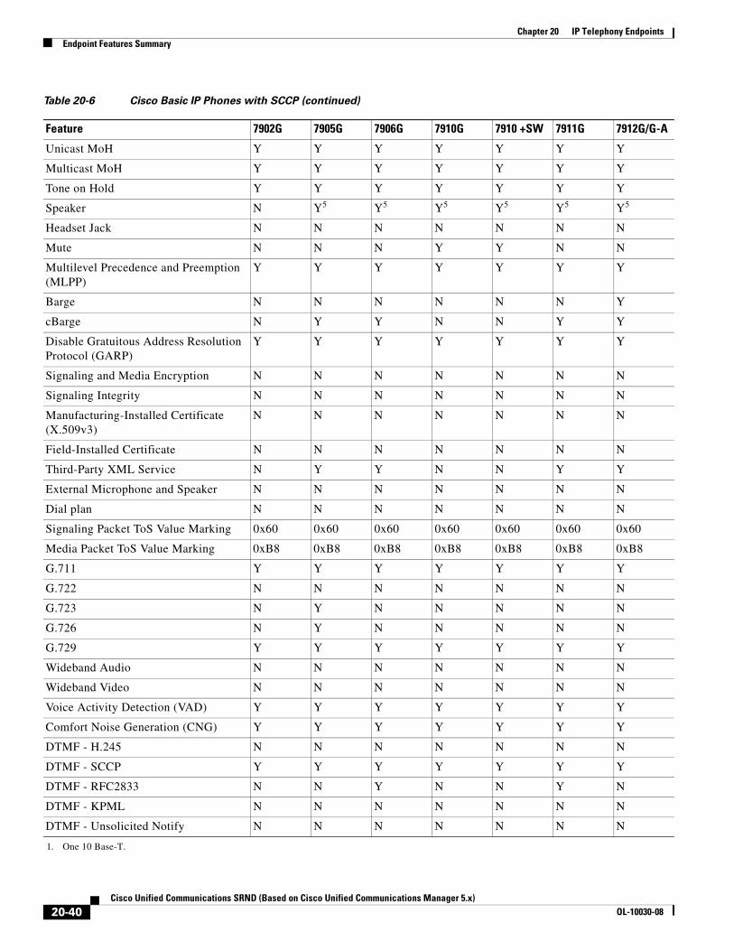
Chapter 20 IP Telephony EndpointsEndpoint Features Summary
Unicast MoH Y Y Y Y Y Y Y
Multicast MoH Y Y Y Y Y Y Y
Tone on Hold Y Y Y Y Y Y Y
Speaker N Y5 Y5 Y5 Y5 Y5 Y5
Headset Jack N N N N N N N
Mute N N N Y Y N N
Multilevel Precedence and Preemption (MLPP)
Y Y Y Y Y Y Y
Barge N N N N N N Y
cBarge N Y Y N N Y Y
Disable Gratuitous Address Resolution Protocol (GARP)
Y Y Y Y Y Y Y
Signaling and Media Encryption N N N N N N N
Signaling Integrity N N N N N N N
Manufacturing-Installed Certificate (X.509v3)
N N N N N N N
Field-Installed Certificate N N N N N N N
Third-Party XML Service N Y Y N N Y Y
External Microphone and Speaker N N N N N N N
Dial plan N N N N N N N
Signaling Packet ToS Value Marking 0x60 0x60 0x60 0x60 0x60 0x60 0x60
Media Packet ToS Value Marking 0xB8 0xB8 0xB8 0xB8 0xB8 0xB8 0xB8
G.711 Y Y Y Y Y Y Y
G.722 N N N N N N N
G.723 N Y N N N N N
G.726 N Y N N N N N
G.729 Y Y Y Y Y Y Y
Wideband Audio N N N N N N N
Wideband Video N N N N N N N
Voice Activity Detection (VAD) Y Y Y Y Y Y Y
Comfort Noise Generation (CNG) Y Y Y Y Y Y Y
DTMF - H.245 N N N N N N N
DTMF - SCCP Y Y Y Y Y Y Y
DTMF - RFC2833 N N Y N N Y N
DTMF - KPML N N N N N N N
DTMF - Unsolicited Notify N N N N N N N
1. One 10 Base-T.
Table 20-6 Cisco Basic IP Phones with SCCP (continued)
Feature 7902G 7905G 7906G 7910G 7910 +SW 7911G 7912G/G-A
20-40Cisco Unified Communications SRND (Based on Cisco Unified Communications Manager 5.x)
OL-10030-08

Chapter 20 IP Telephony EndpointsEndpoint Features Summary
2. One 10/100 Base-T.
3. Two 10/100 Base-T.
4. The Cisco Unified IP Phone 7912G-A has an enhanced version of Ethernet switch.
5. One-way audio monitor mode.
6. Last Number Redial.
Table 20-7 Cisco Basic IP Phones with SIP
Feature 7905G 7906G 7911G 7912G/G-A
Ethernet Connection Y1 Y2 Y3 Y2
Ethernet Switch (PC port) N Y Y Y4
Cisco Power-Over-Ethernet (PoE) Y Y Y Y
IEEE 802.3af Power-Over-Ethernet (PoE) N Y Y N
Localization N Y Y N
Directory Number 1 1 1 1
Maximum number of calls per line 2 50 50 2
Liquid Crystal Display Y Y Y Y
Caller ID Y Y Y Y
Call Waiting Y Y Y Y
Caller ID on Call Waiting Y Y Y Y
Call Hold Y Y Y Y
Blind Transfer Y Y Y Y
Early-attended Transfer N Y Y N
Consultative Transfer Y Y Y Y
Call Forward Y5 Y Y Y5
Auto-Answer N Y6 Y6 N
Ad Hoc Conference Y Y Y Y
Meet-Me Conference N Y Y N
Call Pickup N Y Y N
Group Pickup N Y Y N
Redial Y7 Y Y Y7
Speed Dial Y8 Y Y Y8
On-hook Dialing Y Y Y Y
Voice Mail Access Y Y Y Y
Message Waiting Indicator (MWI) Y Y Y Y
Video call N N N N
Survivable Remote Site Telephony (SRST) Support
Y Y Y Y
Unicast MoH Y Y Y Y
Multicast MoH N Y Y N
20-41Cisco Unified Communications SRND (Based on Cisco Unified Communications Manager 5.x)
OL-10030-08

Chapter 20 IP Telephony EndpointsEndpoint Features Summary
Tone on Hold N N N N
Speaker Y6 Y6 Y6 Y6
Headset Jack N N N N
Mute N Y Y N
Multilevel Precedence and Preemption (MLPP)
N N N N
Barge N Y Y N
cBarge N Y Y N
Disable Gratuitous Address Resolution Protocol (GARP)
Y Y Y Y
Signaling and Media Encryption N Y Y N
Signaling Integrity N Y Y N
Manufacturing-Installed Certificate (X.509v3) N Y Y N
Field-Installed Certificate N N N N
Third-Party XML Service N Y Y N
External Microphone and Speaker N N N N
Dial plan Y Y Y Y
Signaling Packet ToS Value Marking 0x60 0x60 0x60 0x60
Media Packet ToS Value Marking 0xB8 0xB8 0xB8 0xB8
G.711 Y Y Y Y
G.722 N N N N
G.723 N Y Y N
G.726 N N N N
G.729 Y9 Y9 Y9 Y9
Wideband Audio N N N N
Wideband Video N N N N
Voice Activity Detection (VAD) Y Y Y Y
Comfort Noise Generation (CNG) Y Y Y Y
DTMF - H.245 N N N N
DTMF - SCCP N N N N
DTMF - RFC2833 Y Y Y Y
DTMF - KPML N Y Y N
DTMF - Unsolicited Notify N N N N
1. One 10 Base-T.
2. One 10/100 Base-T.
3. Two 10/100 Base-T.
4. The Cisco Unified IP Phone 7912G-A has an enhanced version of Ethernet switch.
Table 20-7 Cisco Basic IP Phones with SIP (continued)
Feature 7905G 7906G 7911G 7912G/G-A
20-42Cisco Unified Communications SRND (Based on Cisco Unified Communications Manager 5.x)
OL-10030-08

Chapter 20 IP Telephony EndpointsEndpoint Features Summary
5. For the Cisco Unified IP Phone 7905G and 7912G with SIP, if CFWDALL is configured on the phone, the phone must be in service to make CFWDALL work because Unified CM has no knowledge of the configuration on the phone. This behavior is different from an SCCP phone, which can be out of service and CFWDALL will still works). If CFWDALL is enabled on the Unified CM User page, Unified CM will handle this change but there will be no status line on the phone to indicate that the call is forwarded. CFWDALL configuration on the Unified CM User page overrides the configuration on the phone.
6. One-way audio monitor mode.
7. Last Number Redial.
8. Speed dial can be configured only on the phone for these models.
9. These IP phone models support G.729b and G.729ab in receiving mode only.
Table 20-8 Cisco Business, Manager, and Executive IP Phones with SCCP
Feature 7940G 7941G/G-GE 7960G 7961G/G-GE 7970G 7971G-GE
Ethernet Connection Y1 Y2 Y1 Y3 Y1 Y4
Ethernet Switch (PC port) Y Y Y Y Y Y
Cisco Power-Over-Ethernet (PoE) Y Y Y Y Y N
IEEE 802.3af Power-Over-Ethernet (PoE)
N Y5 N Y6 Y Y7
Localization Y Y Y Y Y Y
Directory Number 2 2 6 6 8 8
Maximum number of calls per line 200 200 200 200 200 200
Liquid Crystal Display Y Y Y Y Y Y
Caller ID Y Y Y Y Y Y
Call Waiting Y Y Y Y Y Y
Caller ID on Call Waiting Y Y Y Y Y Y
Call Hold Y Y Y Y Y Y
Blind Transfer N N N N N N
Early-Attended Transfer Y Y Y Y Y Y
Consultative Transfer Y Y Y Y Y Y
Call Forward Y Y Y Y Y Y
Auto-Answer Y Y Y Y Y Y
Ad Hoc Conference Y Y Y Y Y Y
Meet-Me Conference Y Y Y Y Y Y
Call Pickup Y Y Y Y Y Y
Group Pickup Y Y Y Y Y Y
Redial Y8 Y8 Y8 Y8 Y8 Y8
Speed Dial Y Y Y Y Y Y
On-hook Dialing Y Y Y Y Y Y
Voice Mail Access Y Y Y Y Y Y
Message Waiting Indicator (MWI) Y Y Y Y Y Y
Video call Y Y Y Y Y Y
20-43Cisco Unified Communications SRND (Based on Cisco Unified Communications Manager 5.x)
OL-10030-08
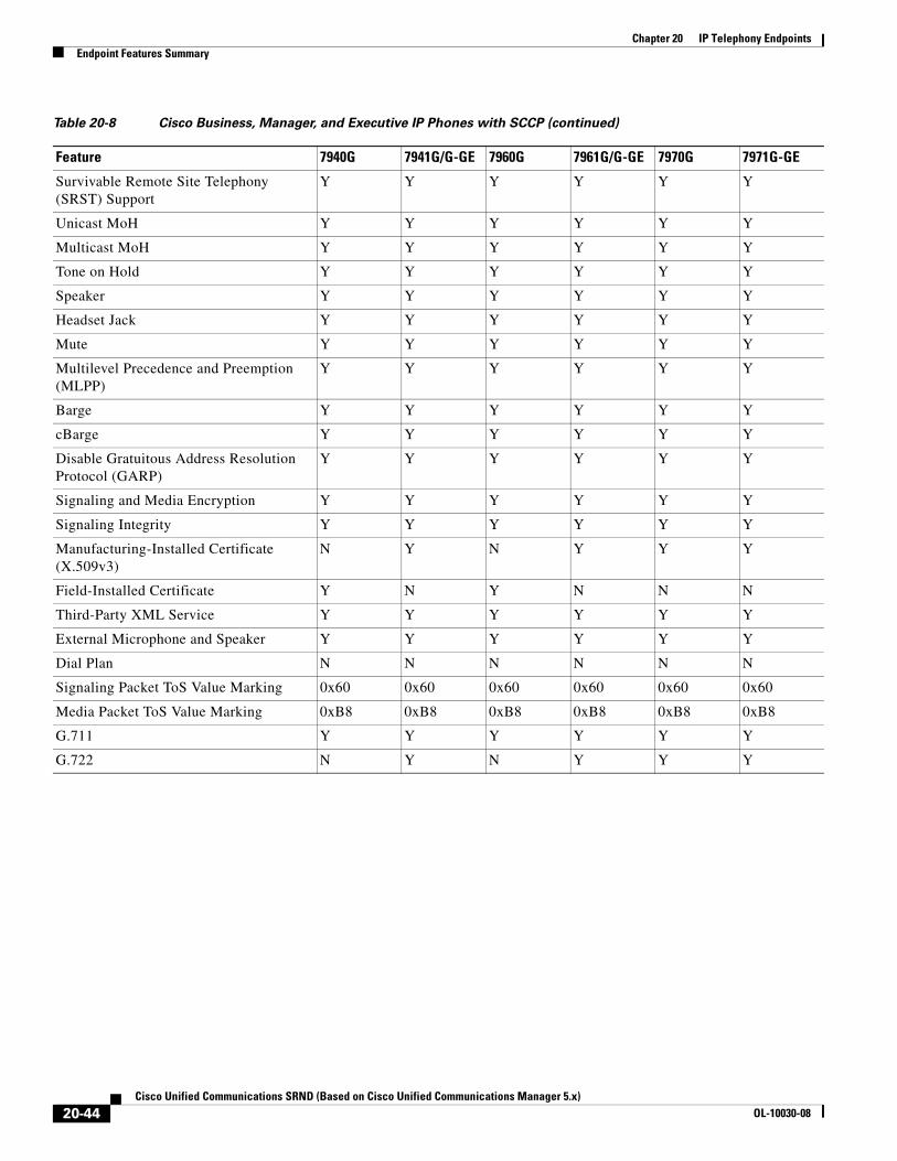
Chapter 20 IP Telephony EndpointsEndpoint Features Summary
Survivable Remote Site Telephony (SRST) Support
Y Y Y Y Y Y
Unicast MoH Y Y Y Y Y Y
Multicast MoH Y Y Y Y Y Y
Tone on Hold Y Y Y Y Y Y
Speaker Y Y Y Y Y Y
Headset Jack Y Y Y Y Y Y
Mute Y Y Y Y Y Y
Multilevel Precedence and Preemption (MLPP)
Y Y Y Y Y Y
Barge Y Y Y Y Y Y
cBarge Y Y Y Y Y Y
Disable Gratuitous Address Resolution Protocol (GARP)
Y Y Y Y Y Y
Signaling and Media Encryption Y Y Y Y Y Y
Signaling Integrity Y Y Y Y Y Y
Manufacturing-Installed Certificate (X.509v3)
N Y N Y Y Y
Field-Installed Certificate Y N Y N N N
Third-Party XML Service Y Y Y Y Y Y
External Microphone and Speaker Y Y Y Y Y Y
Dial Plan N N N N N N
Signaling Packet ToS Value Marking 0x60 0x60 0x60 0x60 0x60 0x60
Media Packet ToS Value Marking 0xB8 0xB8 0xB8 0xB8 0xB8 0xB8
G.711 Y Y Y Y Y Y
G.722 N Y N Y Y Y
Table 20-8 Cisco Business, Manager, and Executive IP Phones with SCCP (continued)
Feature 7940G 7941G/G-GE 7960G 7961G/G-GE 7970G 7971G-GE
20-44Cisco Unified Communications SRND (Based on Cisco Unified Communications Manager 5.x)
OL-10030-08

Chapter 20 IP Telephony EndpointsEndpoint Features Summary
G.723 N N N N N N
G.726 N N N N N N
G.729 Y Y Y Y Y Y
Wideband Audio N N N N N N
Wideband Video N N N N N N
Voice Activity Detection (VAD) Y Y Y Y Y Y
Comfort Noise Generation (CNG) Y Y Y Y Y Y
DTMF - H.245 N N N N N N
DTMF - SCCP Y Y Y Y Y Y
DTMF - RFC2833 N Y N Y Y Y
DTMF - KPML N N N N N N
DTMF - Unsolicited Notify N N N N N N
1. Two 10/100 Base-T.
2. The Cisco Unified IP Phone 7941G has two 10/100 Mbps Ethernet connections, and the Cisco Unified IP Phone 7941G-GE has two 10/100/1000 Mbps Ethernet connections.
3. The Cisco Unified IP Phone 7961G has two 10/100 Mbps Ethernet connections, and the Cisco Unified IP Phone 7961G-GE has two 10/100/1000 Mbps Ethernet connections.
4. The Cisco Unified IP Phone 7970G has two 10/100 Mbps Ethernet connections, and the Cisco Unified IP Phone 7971G-GE has two 10/100/1000 Mbps Ethernet connections.
5. The Cisco Unified IP Phone 7941G supports both Cisco Prestandard Power over Ethernet (PoE) and IEEE 802.3af PoE, and the Cisco Unified IP Phone 7941G-GE supports only IEEE 802.3af PoE.
6. The Cisco Unified IP Phone 7961G supports both Cisco Prestandard PoE and IEEE 802.3af PoE, and the Cisco Unified IP Phone 7961G-GE supports only IEEE 802.3af PoE.
7. The Cisco Unified IP Phone 7971G-GE supports only IEEE 802.3af PoE.
8. Last Number Redial.
Table 20-9 Cisco Business, Manager, and Executive IP Phones with SIP
Feature 7940G 7941G/G-GE 7960G 7961G/G-GE 7970G 7971G-GE
Ethernet Connection Y1 Y2 Y1 Y3 Y1 Y4
Ethernet Switch (PC port) Y Y Y Y Y Y
Cisco Power-Over-Ethernet (PoE) Y Y5 Y Y6 Y N
IEEE 802.3af Power-Over-Ethernet (PoE)
N Y N Y Y Y7
Localization N Y N Y Y Y
Directory Number 2 2 6 6 8 8
Maximum number of calls per line 2 50 2 50 50 50
Liquid Crystal Display Y Y Y Y Y Y
Caller ID Y Y Y Y Y Y
Call Waiting Y Y Y Y Y Y
Caller ID on Call Waiting Y Y Y Y Y Y
Table 20-8 Cisco Business, Manager, and Executive IP Phones with SCCP (continued)
Feature 7940G 7941G/G-GE 7960G 7961G/G-GE 7970G 7971G-GE
20-45Cisco Unified Communications SRND (Based on Cisco Unified Communications Manager 5.x)
OL-10030-08

Chapter 20 IP Telephony EndpointsEndpoint Features Summary
Call Hold Y Y Y Y Y Y
Blind Transfer Y Y Y Y Y Y
Early-Attended Transfer Y Y Y Y Y Y
Consultative Transfer Y Y Y Y Y Y
Call Forward Y8 Y Y8 Y Y Y
Auto-Answer Y9 Y10 Y9 Y Y Y
Ad Hoc Conference Y11 Y Y11 Y Y Y
Meet-Me Conference N Y N Y Y Y
Call Pickup N Y N Y Y Y
Group Pickup N Y N Y Y Y
Redial Y12 Y12 Y12 Y12 Y12 Y12
Speed Dial Y13 Y Y13 Y Y Y
On-hook Dialing N Y N Y Y Y
Voice Mail Access Y Y Y Y Y Y
Message Waiting Indicator (MWI) Y Y Y Y Y Y
Video call N N N N N N
Survivable Remote Site Telephony (SRST) Support
Y Y Y Y Y Y
Unicast MoH Y Y Y Y Y Y
Multicast MoH Y Y Y Y Y Y
Tone on Hold N N N N N N
Speaker Y Y10 Y Y Y Y
Headset Jack Y Y Y Y Y Y
Mute Y Y Y Y Y Y
Multilevel Precedence and Preemption (MLPP)
N N N N N N
Barge N Y N Y Y Y
cBarge N Y N Y Y Y
Disable Gratuitous Address Resolution Protocol (GARP)
Y Y Y Y Y Y
Signaling and Media Encryption N Y N Y Y Y
Signaling Integrity N Y N Y Y Y
Manufacturing-Installed Certificate (X.509v3)
N Y N Y Y Y
Field-Installed Certificate N N N N N N
Third-Party XML Service Y14 Y Y14 Y Y Y
External Microphone and Speaker Y Y Y Y Y Y
Table 20-9 Cisco Business, Manager, and Executive IP Phones with SIP (continued)
Feature 7940G 7941G/G-GE 7960G 7961G/G-GE 7970G 7971G-GE
20-46Cisco Unified Communications SRND (Based on Cisco Unified Communications Manager 5.x)
OL-10030-08

Chapter 20 IP Telephony EndpointsEndpoint Features Summary
Dial Plan Y Y Y Y Y Y
Signaling Packet ToS Value Marking 0x60 0x60 0x60 0x60 0x60 0x60
Media Packet ToS Value Marking 0xB8 0xB8 0xB8 0xB8 0xB8 0xB8
G.711 Y Y Y Y Y Y
G.722 N Y N Y Y Y
G.723 Y Y Y Y Y Y
G.726 N N N N N N
G.729 Y15 Y15 Y15 Y15 Y15 Y15
Wideband Audio N N N N N N
Wideband Video N N N N N N
Voice Activity Detection (VAD) Y Y Y Y Y Y
Comfort Noise Generation (CNG) Y Y Y Y Y Y
DTMF - H.245 N N N N N N
DTMF - SCCP N N N N N N
DTMF - RFC2833 Y Y Y Y Y Y
DTMF - KPML N Y N Y Y Y
DTMF - Unsolicited Notify N N N N N N
1. Two 10/100 Base-T.
2. The Cisco Unified IP Phone 7941G has two 10/100 Mbps Ethernet connections, and the Cisco Unified IP Phone 7941G-GE has two 10/100/1000 Mbps Ethernet connections.
3. The Cisco Unified IP Phone 7961G has two 10/100 Mbps Ethernet connections, and the Cisco Unified IP Phone 7961G-GE has two 10/100/1000 Mbps Ethernet connections.
4. The Cisco Unified IP Phone 7970G has two 10/100 Mbps Ethernet connections, and the Cisco Unified IP Phone 7971G-GE has two 10/100/1000 Mbps Ethernet connections.
5. The Cisco Unified IP Phone 7941G supports both Cisco Prestandard Power over Ethernet (PoE) and IEEE 802.3af PoE, and the Cisco Unified IP Phone 7941G-GE supports only IEEE 802.3af PoE.
6. The Cisco Unified IP Phone 7961G supports both Cisco Prestandard PoE and IEEE 802.3af PoE, and the Cisco Unified IP Phone 7961G-GE supports only IEEE 802.3af PoE.
7. The Cisco Unified IP Phone 7971G-GE supports only IEEE 802.3af PoE.
8. For the Cisco Unified IP Phone 7905, 7912, 7940, or 7960 with SIP, if CFWDALL is configured on the phone, the phone must be in service to make CFWDALL work because Unified CM has no knowledge of the configuration on the phone. This behavior is different from an SCCP phone, which can be out of service and CFWDALL will still works). If CFWDALL is enabled on the Unified CM User page, Unified CM will handle this change but there will be no status line on the phone to indicate that the call is forwarded. CFWDALL configuration on the Unified CM User page overrides the configuration on the phone.
9. This feature can be configured locally on the phone.
10. One-way audio monitor mode.
11. The Cisco Unified IP Phone 7940G and 7960G with IP support only local mixing for ad hoc conferences and up to three parties in the conference.
12. Last Number Redial.
13. Speed dial can be configured only on the phone.
14. With limited support.
15. These IP phone models support G.729b and G.729ab in receiving mode only.
Table 20-9 Cisco Business, Manager, and Executive IP Phones with SIP (continued)
Feature 7940G 7941G/G-GE 7960G 7961G/G-GE 7970G 7971G-GE
20-47Cisco Unified Communications SRND (Based on Cisco Unified Communications Manager 5.x)
OL-10030-08

Chapter 20 IP Telephony EndpointsEndpoint Features Summary
Table 20-10 Specialized Endpoints
Feature 7920 7921G 7936 7985G
Ethernet Connection N N Y1 Y2
Ethernet Switch (PC port) N N N Y
Cisco Power-Over-Ethernet (PoE) N N N N
IEEE 802.3af Power-Over-Ethernet (PoE) N N N Y
Localization Y Y N Y
Directory Number 12 6 1 2
Max number of calls per line 2 2 2 100
Liquid Crystal Display Y Y Y Y
Caller ID Y Y Y Y
Call Waiting Y Y Y Y
Caller ID on Call Waiting Y Y Y Y
Call Hold Y Y Y Y
Blind Transfer N N N N
Early-Attended Transfer Y Y Y Y
Consultative Transfer Y Y Y Y
Call Forward Y Y Y Y
Auto-Answer N Y N Y
Ad Hoc Conference Y Y Y Y
Meet-Me Conference Y Y Y Y
Call Pickup Y Y Y Y
Group Pickup Y Y Y Y
Redial Y3 Y3 Y Y
Speed Dial Y Y N Y
On-hook Dialing Y Y Y Y
Voice Mail Access Y Y N Y
Message Waiting Indicator (MWI) Y Y N Y
Video call N N N Y
Survivable Remote Site Telephony (SRST) Support
Y Y Y Y4
Unicast MoH Y Y Y Y
Multicast MoH Y Y Y N
Tone on Hold Y Y Y Y
Speaker N Y Y Y
Headset Jack Y Y N Y
Mute Y Y Y Y
20-48Cisco Unified Communications SRND (Based on Cisco Unified Communications Manager 5.x)
OL-10030-08

Chapter 20 IP Telephony EndpointsEndpoint Features Summary
Multilevel Precedence and Preemption (MLPP)
N Y N Y
Barge N Y N Y
cBarge N Y N Y
Disable Gratuitous Address Resolution Protocol (GARP)
N Y N N
Signaling and Media Encryption Y Y N N
Signaling Integrity N Y N N
Manufacturing-Installed Certificate (X.509v3) N Y N N
Field-Installed Certificate N Y N N
Third-Party XML Service Y Y N N
External Microphone and Speaker N Y N N
Signaling Packet ToS Value Marking 0x60 0x60 0x60 0x60
Media Packet ToS Value Marking 0xB8 0xB8 0xB8 0x88
G.711 Y Y Y Y
G.722 N N N Y
G.723 N N N N
G.726 N N N N
G.729 Y Y Y Y
Wideband Audio N N N N
Wideband Video N N N N
H.261 N N N Y
H.263 N N N Y
H.263+ N N N Y
H.264 N N N Y
Voice Activity Detection (VAD) Y Y Y Y
Comfort Noise Generation (CNG) Y Y Y Y
DTMF - H.245 N N N N
DTMF - SCCP Y Y Y Y
DTMF - RFC2833 N N N N
1. One 10/100 Base-T.
2. Two 10/100 Base-T.
3. Last Number Redial.
4. Only audio supported on SRST.
Table 20-10 Specialized Endpoints (continued)
Feature 7920 7921G 7936 7985G
20-49Cisco Unified Communications SRND (Based on Cisco Unified Communications Manager 5.x)
OL-10030-08

Chapter 20 IP Telephony EndpointsEndpoint Features Summary
Table 20-11 Software-Based Endpoint Features
Feature Unified Personal Communicator
IP Communicator with SCCP
IP Communicator with SIP
Directory Number 1 8 8
Caller ID Y Y Y
Call Waiting Y Y Y
Caller ID on Call Waiting Y Y Y
Call Hold Y Y Y
Call Transfer N1 Y Y
Call Forward N Y Y
Auto-Answer Y Y Y
Ad Hoc Conference Y2 Y Y
Meet-Me Conference N3 Y N
Web Conference Y N N
Call Pickup N Y Y
Group Pickup N Y Y
Redial Y4 Y4 Y4
Speed Dial N5 Y Y
On-hook Dialing Y Y Y
Voice Mail Access Y Y Y
Message Waiting Indicator (MWI) N Y Y
Video call Y Y6 N
Survivable Remote Site Telephony (SRST) Support
N Y Y
Unicast Music on Hold (MoH) Y Y Y
Multicast Music on Hold (MoH) Y Y Y
Tone on Hold N Y N
Mute Y Y Y
Multilevel Precedence and Preemption (MLPP)
N Y N
Barge N Y Y
cBarge N Y Y
Disable Gratuitous Address Resolution Protocol (GARP)
N N N
Signaling and Media Encryption N N N
Signaling Integrity N N N
Manufacturing-Installed Certificate (X.509v3)
N N N
Field-Installed Certificate N N N
20-50Cisco Unified Communications SRND (Based on Cisco Unified Communications Manager 5.x)
OL-10030-08

Chapter 20 IP Telephony EndpointsEndpoint Features Summary
Third-Party XML Service N Y Y
Signaling Packet ToS Value Marking N 0x60 0x60
Media Packet ToS Value Marking 0xB8 0xB8 0xB8
Skinny Client Control Protocol (SCCP) N Y N
Session Initiation Protocol (SIP) Y N N
G.711 Y Y Y
G.722 N N N
G.723 N N N
G.726 N N N
G.729 Y Y Y7
Wideband Audio N Y Y
Wideband Video N N N
H.261 N N N
H.263 Y N N
H.264 Y N N
Voice Activity Detection (VAD) Y Y Y
Comfort Noise Generation (CNG) Y Y Y
DTMF – H.245 N N N
DTMF – SCCP N Y N
DTMF – RFC2833 Y Y Y
DTMF – KPML Y N Y
1. Cisco Unified Personal Communicator does not have an explicit transfer feature. Calls can be transferred by the other party, or the Cisco Unified Personal Communicator user can merge two calls and then disconnect to obtain the effect of a transfer.
2. Cisco Unified Personal Communicator does not support the “consult, then merge” feature (equivalent to conference on IP phones), but it does support merge (equivalent to join on IP phones) to conference calls.
3. Cisco Unified Personal Communicator cannot create a meet-me conference, but the user can join one by dialing the correct number.
4. Last number redial.
5. Cisco Unified Personal Communicator does not support the Unified CM speed dials page, but it does support dialing from the Contacts (buddy) list in a similar fashion.
6. In combination with Cisco Unified Video Advantage, Cisco IP Communicator operating in SCCP mode supports video calls.
7. Cisco IP Communicator with SIP supports G.729b and G.729ab in receiving mode only.
Table 20-11 Software-Based Endpoint Features (continued)
Feature Unified Personal Communicator
IP Communicator with SCCP
IP Communicator with SIP
20-51Cisco Unified Communications SRND (Based on Cisco Unified Communications Manager 5.x)
OL-10030-08

Chapter 20 IP Telephony EndpointsEndpoint Features Summary
20-52Cisco Unified Communications SRND (Based on Cisco Unified Communications Manager 5.x)
OL-10030-08